EP3709452A1 - Connector assembly with retainer and method of manufacturing same - Google Patents
Connector assembly with retainer and method of manufacturing same Download PDFInfo
- Publication number
- EP3709452A1 EP3709452A1 EP20161426.0A EP20161426A EP3709452A1 EP 3709452 A1 EP3709452 A1 EP 3709452A1 EP 20161426 A EP20161426 A EP 20161426A EP 3709452 A1 EP3709452 A1 EP 3709452A1
- Authority
- EP
- European Patent Office
- Prior art keywords
- conductor
- connector assembly
- retainer
- helical
- twist
- Prior art date
- Legal status (The legal status is an assumption and is not a legal conclusion. Google has not performed a legal analysis and makes no representation as to the accuracy of the status listed.)
- Granted
Links
Images



Classifications
-
- H—ELECTRICITY
- H01—ELECTRIC ELEMENTS
- H01R—ELECTRICALLY-CONDUCTIVE CONNECTIONS; STRUCTURAL ASSOCIATIONS OF A PLURALITY OF MUTUALLY-INSULATED ELECTRICAL CONNECTING ELEMENTS; COUPLING DEVICES; CURRENT COLLECTORS
- H01R13/00—Details of coupling devices of the kinds covered by groups H01R12/70 or H01R24/00 - H01R33/00
- H01R13/58—Means for relieving strain on wire connection, e.g. cord grip, for avoiding loosening of connections between wires and terminals within a coupling device terminating a cable
- H01R13/5804—Means for relieving strain on wire connection, e.g. cord grip, for avoiding loosening of connections between wires and terminals within a coupling device terminating a cable comprising a separate cable clamping part
- H01R13/5816—Means for relieving strain on wire connection, e.g. cord grip, for avoiding loosening of connections between wires and terminals within a coupling device terminating a cable comprising a separate cable clamping part for cables passing through an aperture in a housing wall, the separate part being captured between cable and contour of aperture
-
- H—ELECTRICITY
- H01—ELECTRIC ELEMENTS
- H01R—ELECTRICALLY-CONDUCTIVE CONNECTIONS; STRUCTURAL ASSOCIATIONS OF A PLURALITY OF MUTUALLY-INSULATED ELECTRICAL CONNECTING ELEMENTS; COUPLING DEVICES; CURRENT COLLECTORS
- H01R13/00—Details of coupling devices of the kinds covered by groups H01R12/70 or H01R24/00 - H01R33/00
- H01R13/40—Securing contact members in or to a base or case; Insulating of contact members
- H01R13/42—Securing in a demountable manner
-
- H—ELECTRICITY
- H01—ELECTRIC ELEMENTS
- H01R—ELECTRICALLY-CONDUCTIVE CONNECTIONS; STRUCTURAL ASSOCIATIONS OF A PLURALITY OF MUTUALLY-INSULATED ELECTRICAL CONNECTING ELEMENTS; COUPLING DEVICES; CURRENT COLLECTORS
- H01R13/00—Details of coupling devices of the kinds covered by groups H01R12/70 or H01R24/00 - H01R33/00
- H01R13/58—Means for relieving strain on wire connection, e.g. cord grip, for avoiding loosening of connections between wires and terminals within a coupling device terminating a cable
- H01R13/5833—Means for relieving strain on wire connection, e.g. cord grip, for avoiding loosening of connections between wires and terminals within a coupling device terminating a cable the cable being forced in a tortuous or curved path, e.g. knots in cable
-
- H—ELECTRICITY
- H01—ELECTRIC ELEMENTS
- H01R—ELECTRICALLY-CONDUCTIVE CONNECTIONS; STRUCTURAL ASSOCIATIONS OF A PLURALITY OF MUTUALLY-INSULATED ELECTRICAL CONNECTING ELEMENTS; COUPLING DEVICES; CURRENT COLLECTORS
- H01R13/00—Details of coupling devices of the kinds covered by groups H01R12/70 or H01R24/00 - H01R33/00
- H01R13/46—Bases; Cases
- H01R13/502—Bases; Cases composed of different pieces
- H01R13/504—Bases; Cases composed of different pieces different pieces being moulded, cemented, welded, e.g. ultrasonic welding, or swaged together
- H01R13/5045—Bases; Cases composed of different pieces different pieces being moulded, cemented, welded, e.g. ultrasonic welding, or swaged together different pieces being assembled by press-fit
-
- H—ELECTRICITY
- H01—ELECTRIC ELEMENTS
- H01R—ELECTRICALLY-CONDUCTIVE CONNECTIONS; STRUCTURAL ASSOCIATIONS OF A PLURALITY OF MUTUALLY-INSULATED ELECTRICAL CONNECTING ELEMENTS; COUPLING DEVICES; CURRENT COLLECTORS
- H01R13/00—Details of coupling devices of the kinds covered by groups H01R12/70 or H01R24/00 - H01R33/00
- H01R13/62—Means for facilitating engagement or disengagement of coupling parts or for holding them in engagement
-
- H—ELECTRICITY
- H01—ELECTRIC ELEMENTS
- H01R—ELECTRICALLY-CONDUCTIVE CONNECTIONS; STRUCTURAL ASSOCIATIONS OF A PLURALITY OF MUTUALLY-INSULATED ELECTRICAL CONNECTING ELEMENTS; COUPLING DEVICES; CURRENT COLLECTORS
- H01R4/00—Electrically-conductive connections between two or more conductive members in direct contact, i.e. touching one another; Means for effecting or maintaining such contact; Electrically-conductive connections having two or more spaced connecting locations for conductors and using contact members penetrating insulation
- H01R4/10—Electrically-conductive connections between two or more conductive members in direct contact, i.e. touching one another; Means for effecting or maintaining such contact; Electrically-conductive connections having two or more spaced connecting locations for conductors and using contact members penetrating insulation effected solely by twisting, wrapping, bending, crimping, or other permanent deformation
- H01R4/12—Electrically-conductive connections between two or more conductive members in direct contact, i.e. touching one another; Means for effecting or maintaining such contact; Electrically-conductive connections having two or more spaced connecting locations for conductors and using contact members penetrating insulation effected solely by twisting, wrapping, bending, crimping, or other permanent deformation by twisting
-
- H—ELECTRICITY
- H01—ELECTRIC ELEMENTS
- H01R—ELECTRICALLY-CONDUCTIVE CONNECTIONS; STRUCTURAL ASSOCIATIONS OF A PLURALITY OF MUTUALLY-INSULATED ELECTRICAL CONNECTING ELEMENTS; COUPLING DEVICES; CURRENT COLLECTORS
- H01R4/00—Electrically-conductive connections between two or more conductive members in direct contact, i.e. touching one another; Means for effecting or maintaining such contact; Electrically-conductive connections having two or more spaced connecting locations for conductors and using contact members penetrating insulation
- H01R4/10—Electrically-conductive connections between two or more conductive members in direct contact, i.e. touching one another; Means for effecting or maintaining such contact; Electrically-conductive connections having two or more spaced connecting locations for conductors and using contact members penetrating insulation effected solely by twisting, wrapping, bending, crimping, or other permanent deformation
- H01R4/18—Electrically-conductive connections between two or more conductive members in direct contact, i.e. touching one another; Means for effecting or maintaining such contact; Electrically-conductive connections having two or more spaced connecting locations for conductors and using contact members penetrating insulation effected solely by twisting, wrapping, bending, crimping, or other permanent deformation by crimping
- H01R4/183—Electrically-conductive connections between two or more conductive members in direct contact, i.e. touching one another; Means for effecting or maintaining such contact; Electrically-conductive connections having two or more spaced connecting locations for conductors and using contact members penetrating insulation effected solely by twisting, wrapping, bending, crimping, or other permanent deformation by crimping for cylindrical elongated bodies, e.g. cables having circular cross-section
- H01R4/184—Electrically-conductive connections between two or more conductive members in direct contact, i.e. touching one another; Means for effecting or maintaining such contact; Electrically-conductive connections having two or more spaced connecting locations for conductors and using contact members penetrating insulation effected solely by twisting, wrapping, bending, crimping, or other permanent deformation by crimping for cylindrical elongated bodies, e.g. cables having circular cross-section comprising a U-shaped wire-receiving portion
- H01R4/185—Electrically-conductive connections between two or more conductive members in direct contact, i.e. touching one another; Means for effecting or maintaining such contact; Electrically-conductive connections having two or more spaced connecting locations for conductors and using contact members penetrating insulation effected solely by twisting, wrapping, bending, crimping, or other permanent deformation by crimping for cylindrical elongated bodies, e.g. cables having circular cross-section comprising a U-shaped wire-receiving portion combined with a U-shaped insulation-receiving portion
-
- H—ELECTRICITY
- H01—ELECTRIC ELEMENTS
- H01R—ELECTRICALLY-CONDUCTIVE CONNECTIONS; STRUCTURAL ASSOCIATIONS OF A PLURALITY OF MUTUALLY-INSULATED ELECTRICAL CONNECTING ELEMENTS; COUPLING DEVICES; CURRENT COLLECTORS
- H01R13/00—Details of coupling devices of the kinds covered by groups H01R12/70 or H01R24/00 - H01R33/00
- H01R13/46—Bases; Cases
- H01R13/52—Dustproof, splashproof, drip-proof, waterproof, or flameproof cases
- H01R13/5205—Sealing means between cable and housing, e.g. grommet
-
- H—ELECTRICITY
- H01—ELECTRIC ELEMENTS
- H01R—ELECTRICALLY-CONDUCTIVE CONNECTIONS; STRUCTURAL ASSOCIATIONS OF A PLURALITY OF MUTUALLY-INSULATED ELECTRICAL CONNECTING ELEMENTS; COUPLING DEVICES; CURRENT COLLECTORS
- H01R13/00—Details of coupling devices of the kinds covered by groups H01R12/70 or H01R24/00 - H01R33/00
- H01R13/62—Means for facilitating engagement or disengagement of coupling parts or for holding them in engagement
- H01R13/627—Snap or like fastening
- H01R13/6271—Latching means integral with the housing
- H01R13/6272—Latching means integral with the housing comprising a single latching arm
-
- H—ELECTRICITY
- H01—ELECTRIC ELEMENTS
- H01R—ELECTRICALLY-CONDUCTIVE CONNECTIONS; STRUCTURAL ASSOCIATIONS OF A PLURALITY OF MUTUALLY-INSULATED ELECTRICAL CONNECTING ELEMENTS; COUPLING DEVICES; CURRENT COLLECTORS
- H01R2103/00—Two poles
-
- H—ELECTRICITY
- H01—ELECTRIC ELEMENTS
- H01R—ELECTRICALLY-CONDUCTIVE CONNECTIONS; STRUCTURAL ASSOCIATIONS OF A PLURALITY OF MUTUALLY-INSULATED ELECTRICAL CONNECTING ELEMENTS; COUPLING DEVICES; CURRENT COLLECTORS
- H01R43/00—Apparatus or processes specially adapted for manufacturing, assembling, maintaining, or repairing of line connectors or current collectors or for joining electric conductors
- H01R43/18—Apparatus or processes specially adapted for manufacturing, assembling, maintaining, or repairing of line connectors or current collectors or for joining electric conductors for manufacturing bases or cases for contact members
Definitions
- the cables 102 contact inner side walls of the helical channels 112, 114 as the cables 102 are wrapped within the helical channels 112, 114. Reaction forces are provided by the side walls and are applied in different axial directions as the cables 102 extend along the helical channels 112, 114, thereby dampening vibrations applied to the cables 102 in more than axial plane and reducing vibration transmitted by the cables 102 to the terminals 104 that could cause fretting corrosion when the terminals 104 are mated with corresponding mating terminals (not shown).
- Fig. 6 illustrates a non-limiting example of a method 200 of manufacturing a connector assembly, such as the connector assembly 100.
- the method 200 includes the following steps:
Landscapes
- Connector Housings Or Holding Contact Members (AREA)
Abstract
Description
- The invention generally relates to a connector assembly configured to retain to a conductor within the connector assembly, particularly to a connector assembly with a retainer that includes features which helically twists the conductors.
- The present invention will now be described, by way of example with reference to the accompanying drawings, in which:
-
Fig. 1 is an exploded perspective view of a connector assembly according to one embodiment of the invention; -
Fig. 2 is a partially assembled view of the connector assembly ofFig. 1 according to one embodiment of the invention; -
Fig. 3 is a top plan view of a conductor retainer and conductors of the connector assembly ofFig. 1 according to one embodiment of the invention; -
Fig. 4 is a fully assembled view of the connector assembly ofFig. 1 according to one embodiment of the invention; -
Fig. 5 is a cut away view of the connector assembly ofFig. 1 according to one embodiment of the invention; and -
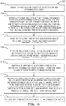
Fig. 6 is a flow chart of a method of manufacturing the connector assembly ofFig. 1 according to another embodiment of the invention. - Reference will now be made in detail to embodiments, examples of which are illustrated in the accompanying drawings. In the following detailed description, numerous specific details are set forth in order to provide a thorough understanding of the various described embodiments. However, it will be apparent to one of ordinary skill in the art that the various described embodiments may be practiced without these specific details. In other instances, well-known methods, procedures, components, circuits, and networks have not been described in detail so as not to unnecessarily obscure aspects of the embodiments.
-
Fig. 1 illustrates a nonlimiting example of aconnector assembly 100 used to interconnect elongate conductors. In this illustrated example, the conductors are insulated wire electrical cables, hereinafter referred to ascables 102.Electrical terminals 104 formed of a conductive material, such as a tin-plated copper material, are attached to ends of thecables 102. Theseterminals 104 are received and retained within terminal cavities 106 (seeFig. 5 ) defined within aconnector body 108 of theconnector assembly 100. Theconnector body 108 is formed of a dielectric material, such as polyamide (PA, also known as nylon) or polybutylene terephthalate (PBT). Theconnector assembly 100 further includes a conductor retainer, hereinafter referred to as acable retainer 110 that defines a firsthelical channel 112 and a secondhelical channel 114. The firsthelical channel 112 extends along a first longitudinal axis X1and is substantially parallel to a longitudinal axis of the connector body. The secondhelical channel 114 extends along a second longitudinal axis X2and is substantially parallel to the first longitudinal axis X1. As used herein, substantially parallel is within 15 degrees of absolutely parallel. Thecable retainer 110 also defines anentrance opening 116 at one end of each of thehelical channels cables 102 enter thecable retainer 110 and anexit opening 118 on the other end of each of thehelical channels cables 102 exit thecable retainer 110. Thecable retainer 110 is also formed of a dielectric material, such as PA or PBT. Thecables 102 are disposed within the pair ofhelical channels helical channels helical channels cables 102 to form a helical twist generally having the same degree of twist as thehelical channels - The
cable retainer 110 may advantageously be formed using an additive manufacturing process, e.g. 3D printing, stereolithography, digital light processing, fused deposition modeling, fused filament fabrication, selective laser sintering, selecting heat sintering, multi-jet modeling, multi-jet fusion, electronic beam melting, and/or laminated object manufacturing. An additive manufacturing process avoids the complicated tooling that would be required to form thehelical channels cable retainer 110 using an injection molding process typically used to form the dielectric parts of a connector assembly. An additive manufacturing process also avoids material waste associated with material removal processes that could alternatively be used to form thecable retainer 110, such as milling, or grinding. - As illustrated in the nonlimiting example of
Fig. 1 , eachhelical channel helical channel cables 102. The helix angle of each of thehelical channels helical channels - As shown in the nonlimiting example of
Fig. 1 , the firsthelical channel 112 has a right hand helical twist and the secondhelical channel 114 has a left hand helical twist. That is to say, the firsthelical channel 112 twists in a clockwise direction along the first channel from the entrance opening 116 to the exit opening 118 while the secondhelical channel 114 twists in a counterclockwise direction along the second channel from the entrance opening 116 to the exit opening 118. Alternative embodiments of the cable retainer having two or more helical channels may be envisioned in which all of the helical channels are only twist in a clockwise direction or only twist in a counterclockwise direction. -
Figs. 2 through 4 illustrate a non-limiting process of assembling theconnector assembly 100. As shown inFig. 2 , theterminals 104 are inserted within theconnector body 108 and thecables 102 extends from arear opening 120 in theconnector body 108 . As further shown inFig. 2 , thecables 102 are then inserted into the virtuallyoriented entrance openings 116 of thecable retainer 110. As shown inFig. 3 , thecables 102 are placed in the entrance opening 116 in each of thehelical channels cables 102 contact the inner surfaces of thehelical channels helical channels cable retainer 110 is pushed into therear opening 120 in theconnector body 108. The inventors have discovered that providing the helix angle of each of thehelical channels cables 102 in thehelical channels cable retainer 110 is pushed into therear opening 120. Thecables 102 then exit thehelical channels oriented exit openings 118. In this nonlimiting example, theentrance openings 116 andexit openings 118 are offset by about 90 degrees. Theentrance openings 116 are generally aligned with the longitudinal axes X1 and X2 and theexit openings 118 are laterally offset from the longitudinal axes X1 and X2. - The
cables 102 contact inner side walls of thehelical channels cables 102 are wrapped within thehelical channels cables 102 extend along thehelical channels cables 102 in more than axial plane and reducing vibration transmitted by thecables 102 to theterminals 104 that could cause fretting corrosion when theterminals 104 are mated with corresponding mating terminals (not shown). - As shown in
Fig. 4 , thecable retainer 110 is fully inserted within therear opening 120 and is attached to theconnector body 108. In the illustrated embodiment, thecable retainer 110 is attached theconnector body 108 by an interference fit between thecable retainer 110 and therear opening 120 of theconnector body 108. In alternative embodiments, thecable retainer 110 may be attached to theconnector body 108 by other means, such as latching features, threaded fasteners, or adhesives. - The
cables 102 in the illustrated non-limiting example ofFig. 1 havecable seals 122 attached to each of thecables 102. Thecable seals 122 are configured to inhibit the intrusion of contaminants, such as water, oil, or dirt, through therear opening 120 into theterminal cavity 106. Thecable retainer 110 may be further configured to retain thecable seals 122 and theterminals 104 within theconnector body 108 as illustrated in the non-limiting example shown inFig. 6 . -
Fig. 6 illustrates a non-limiting example of amethod 200 of manufacturing a connector assembly, such as theconnector assembly 100. Themethod 200 includes the following steps: -
STEP 202 includes inserting a first end of afirst conductor 102, such as afirst cable 102, in aconnector body 108 as shown in the nonlimiting example ofFig. 2 ; -
STEP 204 includes inserting a second end of thefirst conductor 102 into acable retainer 110 that is configured to retain thefirst conductor 102 within theconnector body 108 as shown inFig. 3 . Thecable retainer 110 defines a firsthelical channel 112 that extends along the longitudinal axis X1 in which a portion of thefirst conductor 102 is disposed. The firsthelical channel 112 helically twists at least 90 degrees. Insertion of thefirst conductor 102 into the firsthelical channel 112 causes thefirst conductor 102 to helically twist at least 90 degrees; -
STEP 206 is includes wrapping the second end of the conductor about the conductor retainer, thereby helically twisting the conductor.STEP 206 may be performed when the first helical channel 12 is an open channel having a U-shaped cross section.STEP 206 is performed prior toSTEP 214. -
STEP 208 includes applying an insertion force to the second end of the conductor as the conductor is inserted into a conductor retainer, thereby helically twisting the conductor.STEP 208 may be performed when the firsthelical channel 112 is a closed channel.STEP 208 is performed prior toSTEP 214. -
STEP 210 includes inserting a third end of asecond conductor 102, such asecond cable 102, that is distinct from thefirst conductor 102 within theconnector body 108 as shown in the nonlimiting example ofFig. 2 ; -
STEP 212 includes inserting a fourth end of thesecond conductor 102 into thecable retainer 110 as shown inFig. 3 . Thecable retainer 110 defines a secondhelical channel 114 that is distinct from the firsthelical channel 112. The secondhelical channel 114 extends along the longitudinal axis X2. A portion of the conductor is disposed within the secondhelical channel 114. The secondhelical channel 114 twists at least 90 degrees. Insertion of thesecond conductor 102 into the secondhelical channel 114 causes thesecond conductor 102 to helically twist at least 90 degrees; and -
STEP 214 includes attaching thecable retainer 110 to theconnector body 108 as shown in the nonlimiting example ofFig. 4 . - According to a non-limiting example shown in
Fig. 3 , the firsthelical channel 112 has a right hand helical twist and the secondhelical channel 114 has a left hand helical twist. While the illustrated embodiment of theconnector assembly 100 accommodates a single pair ofcables 102, alternative embodiments of the connector assembly may accommodate a single cable or may accommodate more than two cables. The cables may be arranged in cable pairs in which the cable retainer causes one cable of the cable pair to have a right hand helical twist while the other cable of the cable pair to has a left hand helical twist. - According to a non-limiting example shown in
Fig. 3 , thehelical channels Fig. 3 as they pass through the helical channels due to the insertion forces applied to the cables and contact with the inner walls of the helical channels. - The example presented herein is directed to a
connector assembly 100 in which the conductors are insulatedelectrical cables 102. However, alternative embodiments of the connector assembly may be envisioned in which the conductors are fiber optic cables, pneumatic tubes, hydraulic tubes, or a hybrid assembly having a combination of any of these conductors. These conductors may be terminated by fittings which may be characterized as terminals. - According to another alternative embodiment of the connector assembly, the cable retainer may be moveable attached to the connector body and may be moved from a pre-staged position that allows insertion of the terminals into the terminal cavities to a staged position in which the cable retainer is fully seated in the rear opening; similarly situated as in the example illustrated in
Fig. 4 . - Accordingly, a
connector assembly 100 and amethod 200 of manufacturing a connector assembly is presented. Theconnector assembly 100 includes acable retainer 110 that provides the benefit of isolating motion of thecables 102 from theterminals 104 so that motion and forces acting on thecables 102 extending beyond theconnector body 108 cannot induce motion or forces on theterminals 104 within theconnector body 108. This isolation of theterminals 104 reduces relative motion fretting and plating wear at the contact interface between theterminals 104 and corresponding mating terminals (not shown), thereby increasing the reliability and service life of theconnector assembly 100. - Because the
cables 102 of theconnector assembly 100 are not pinched or clamped by thecable retainer 110 as in prior art cable retainers, the fit between thecables 102 and thecable retainer 110 is not prone to loosening due to thermal cycling of theconnector assembly 100 as in prior art cable retainers that rely on cable pinching or clamping. Therefore, theconnector assembly 100 is suited for applications that experience changes in temperature, such as vehicle engine bay applications. Since the U-shapedhelical channels cables 102, thecables 102 fit within thehelical channels cable retainer 110 may accommodate any cable size as long as the diameter of thecables 102 is less than the width of thehelical channels - Without subscribing to any particular theory of operation, the
cable retainer 110 effectively isolates motion of thecables 102 from theterminals 104 because thecables 102 are engaged with thehelical channels helical channels cables 102 from theterminals 104 since thehelical channels - The
cable retainer 110 further provides the benefit of acting as a cable seal retainer whenconnector assembly 100 includes cable seals 122. - While this invention has been described in terms of the preferred embodiments thereof, it is not intended to be so limited, but rather only to the extent set forth in the claims that follow. For example, the above-described embodiments (and/or aspects thereof) may be used in combination with each other. In addition, many modifications may be made to configure a particular situation or material to the teachings of the invention without departing from its scope. Dimensions, types of materials, orientations of the various components, and the number and positions of the various components described herein are intended to define parameters of certain embodiments, and are by no means limiting and are merely prototypical embodiments.
- Many other embodiments and modifications within the spirit and scope of the claims will be apparent to those of skill in the art upon reviewing the above description. The scope of the invention should, therefore, be determined with reference to the following claims, along with the full scope of equivalents to which such claims are entitled.
- As used herein, 'one or more' includes a function being performed by one element, a function being performed by more than one element, e.g., in a distributed fashion, several functions being performed by one element, several functions being performed by several elements, or any combination of the above.
- It will also be understood that, although the terms first, second, etc. are, in some instances, used herein to describe various elements, these elements should not be limited by these terms. These terms are only used to distinguish one element from another. For example, a first contact could be termed a second contact, and, similarly, a second contact could be termed a first contact, without departing from the scope of the various described embodiments. The first contact and the second contact are both contacts, but they are not the same contact.
- The terminology used in the description of the various described embodiments herein is for the purpose of describing particular embodiments only and is not intended to be limiting. As used in the description of the various described embodiments and the appended claims, the singular forms "a", "an" and "the" are intended to include the plural forms as well, unless the context clearly indicates otherwise. It will also be understood that the term "and/or" as used herein refers to and encompasses any and all possible combinations of one or more of the associated listed items. It will be further understood that the terms "includes," "including," "comprises," and/or "comprising," when used in this specification, specify the presence of stated features, integers, steps, operations, elements, and/or components, but do not preclude the presence or addition of one or more other features, integers, steps, operations, elements, components, and/or groups thereof.
- As used herein, the term "if' is, optionally, construed to mean "when" or "upon" or "in response to determining" or "in response to detecting," depending on the context. Similarly, the phrase "if it is determined" or "if [a stated condition or event] is detected" is, optionally, construed to mean "upon determining" or "in response to determining" or "upon detecting [the stated condition or event]" or "in response to detecting [the stated condition or event]," depending on the context.
- Additionally, while terms of ordinance or orientation may be used herein these elements should not be limited by these terms. All terms of ordinance or orientation, unless stated otherwise, are used for purposes distinguishing one element from another, and do not denote any particular order, order of operations, direction or orientation unless stated otherwise.
Claims (12)
- A connector assembly (100), comprising:
a conductor retainer (110) configured to retain a conductor (102) within a connector body (108) of the connector assembly (100), wherein the conductor retainer (110) causes the conductor (102) to helically twist at least 90 degrees about a longitudinal axis. - The connector assembly (100) according to claim 1, wherein the conductor (102) helically twists after the conductor (102) is inserted within a first opening defined by the conductor retainer (110) and the conductor (102) exits a second opening defined by the conductor retainer (110).
- The connector assembly (100) according to claim 1 or 2, wherein the conductor (102) contacts an inner side wall of a helical channel (112) defined within the conductor retainer (110) as the conductor (102) is helically twisted.
- The connector assembly (100) according to any one of claims 1 to 3, wherein the conductor retainer (110) defines a helical channel (112) extending along the longitudinal axis which causes the conductor (102) to helically twist.
- The connector assembly (100) according to claim 4, wherein an insertion force applied to the conductor (102) causes the conductor (102) to helically twist as the conductor (102) is inserted within the conductor retainer (110).
- The connector assembly (100) according to claim 5, wherein the conductor (102) contacts an inner surface of the helical channel (112) and is twisted within the helical channel (112) by the insertion force applied to the conductor retainer (110) as the conductor retainer (110) is pushed into a rear opening (120) in the connector body (108).
- The connector assembly (100) according to any one of claims 1 to 6, wherein the conductor (102) is a first conductor (102) and the longitudinal axis is a first longitudinal axis, wherein the conductor retainer (110) is configured to retain a second conductor (102) distinct from the first conductor (102) within the connector body (108) and wherein the conductor retainer (110) causes the second conductor (102) to helically twist at least 90 degrees about a second longitudinal axis.
- The connector assembly (100) according to claim 7, wherein the first conductor (102) has a right hand helical twist and the second conductor (102) has a left hand helical twist.
- The connector assembly (100) according to claim 7 or 8, wherein the first conductor (102) and the second conductor (102) are selected from a group consisting of: wire electrical cables (102), fiber optic cables (102), pneumatic tubing, and hydraulic tubing.
- The connector assembly (100) according to claim 9, wherein the first conductor (102) and the second conductor (102) have terminals (104) attached and wherein the terminals (104) are retained within the connector body (108).
- The connector assembly (100) according to claim 10, wherein the first conductor (102) and the second conductor (102) have conductor (102) seals attached and wherein the conductor retainer (110) is further configured to retain the conductor (102) seals within the connector body (108).
- The connector assembly (100) according to claim 10 or 11, wherein helical twisting of the conductor (102) is configured to inhibit transmission of motion of the first conductor (102) and the second conductor (102) to the terminals (104).
Applications Claiming Priority (1)
| Application Number | Priority Date | Filing Date | Title |
|---|---|---|---|
| US16/353,649 US10637176B1 (en) | 2019-03-14 | 2019-03-14 | Connector assembly with retainer |
Publications (2)
| Publication Number | Publication Date |
|---|---|
| EP3709452A1 true EP3709452A1 (en) | 2020-09-16 |
| EP3709452B1 EP3709452B1 (en) | 2022-07-20 |
Family
ID=69779987
Family Applications (1)
| Application Number | Title | Priority Date | Filing Date |
|---|---|---|---|
| EP20161426.0A Active EP3709452B1 (en) | 2019-03-14 | 2020-03-06 | Connector assembly with retainer |
Country Status (3)
| Country | Link |
|---|---|
| US (1) | US10637176B1 (en) |
| EP (1) | EP3709452B1 (en) |
| CN (1) | CN111697387A (en) |
Families Citing this family (8)
| Publication number | Priority date | Publication date | Assignee | Title |
|---|---|---|---|---|
| US20240047956A1 (en) * | 2018-11-07 | 2024-02-08 | Ls Cable & System Ltd. | Jointing system of power cable |
| US12308140B2 (en) * | 2020-12-30 | 2025-05-20 | Eaton Intelligent Power Limited | Additively manufactured cable gland |
| WO2022159587A1 (en) * | 2021-01-21 | 2022-07-28 | Commscope Technologies Llc | Connector for a single twisted pair of conductors |
| US11695234B2 (en) * | 2021-02-26 | 2023-07-04 | Te Connectivity Solutions Gmbh | Cable organizer for a pluggable module |
| DE102021117003A1 (en) | 2021-07-01 | 2023-01-05 | Amphenol-Tuchel Electronics Gesellschaft mit beschränkter Haftung | Plug connection for airbag ignition systems |
| AU2022338887A1 (en) * | 2021-08-30 | 2023-09-07 | Hubbell Incorporated | Adaptive seal for cable glands |
| EP4293846A1 (en) * | 2022-06-13 | 2023-12-20 | NKT HV Cables AB | Cable end sealing arrangement for a cable and method for connecting a metallic sheath of a cable end of the cable to a metallic casing of the cable end sealing arrangement |
| CN117410729B (en) * | 2023-12-13 | 2024-03-12 | 黑龙江瑞兴科技股份有限公司 | Circuit connector |
Citations (4)
| Publication number | Priority date | Publication date | Assignee | Title |
|---|---|---|---|---|
| US20080108246A1 (en) * | 2006-11-02 | 2008-05-08 | John Michael Landis | Wire retention connector system |
| US7680544B1 (en) * | 2006-11-07 | 2010-03-16 | Pacesetter, Inc. | Fatigue resistant design for leads employing multi-strand cables as primary conductors |
| WO2012120258A2 (en) * | 2011-03-10 | 2012-09-13 | Sensor Developments As | Tubular electric cable fittings with strain relief |
| US20140120779A1 (en) * | 2012-10-25 | 2014-05-01 | Molex Incorporated | Connector Guide For Orienting Wires For Termination |
Family Cites Families (34)
| Publication number | Priority date | Publication date | Assignee | Title |
|---|---|---|---|---|
| US571761A (en) * | 1896-11-24 | Electric-light-cord adjuster | ||
| US2920129A (en) * | 1956-12-05 | 1960-01-05 | Illinois Tool Works | Strain relief grommet |
| US3806992A (en) * | 1973-08-13 | 1974-04-30 | Gte Automatic Electric Lab Inc | Cable tensioner |
| JPS6210951Y2 (en) * | 1978-10-23 | 1987-03-14 | ||
| US4881909A (en) * | 1988-10-31 | 1989-11-21 | Whirlpool Corporation | Hose assembly for canister vacuum cleaner |
| US5255866A (en) * | 1990-10-19 | 1993-10-26 | Leviton Manufacturing Co., Inc. | Apparatus for isolating a cord section from tension |
| US5416273A (en) * | 1993-11-22 | 1995-05-16 | The United States Of America As Represented By The Secretary Of The Navy | Strain relief for flexible wire at fixed junction |
| WO1998029055A2 (en) * | 1996-12-19 | 1998-07-09 | Medtronic, Inc. | Medical electrical lead |
| US6249708B1 (en) * | 1997-08-26 | 2001-06-19 | Angeion Corporation | Fluted channel construction for a multi-conductor catheter lead |
| US6099345A (en) * | 1999-04-23 | 2000-08-08 | Hubbell Incorporated | Wire spacers for connecting cables to connectors |
| US6524128B2 (en) * | 2000-06-02 | 2003-02-25 | Stewart Connector Systems, Inc. | Modular plug wire aligner |
| US7555349B2 (en) * | 2000-09-26 | 2009-06-30 | Advanced Neuromodulation Systems, Inc. | Lead body and method of lead body construction |
| US6406325B1 (en) * | 2000-12-28 | 2002-06-18 | Surtec Industries Inc. | Connector plug for network cabling |
| US6811445B2 (en) * | 2002-04-22 | 2004-11-02 | Panduit Corp. | Modular cable termination plug |
| TW566719U (en) * | 2002-05-30 | 2003-12-11 | Yuan-Huei Peng | Network plug structure |
| SE525049C2 (en) * | 2002-12-09 | 2004-11-16 | Atlas Copco Tools Ab | Multi-Conductor Connector |
| DE10320228A1 (en) * | 2003-05-05 | 2004-11-25 | Stm Medizintechnik Starnberg Gmbh | endoscope shaft |
| DE602004005066T2 (en) * | 2003-10-02 | 2007-10-31 | Medtronic, Inc., Minneapolis | IMPLANTABLE MEDICAL AND MANUFACTURING PROCESS |
| US20080014801A1 (en) * | 2003-11-14 | 2008-01-17 | Luc Milette | Wire guide and connector assembly using same |
| US7223112B2 (en) * | 2004-01-09 | 2007-05-29 | Hubbell Incorporated | Communication connector to optimize crosstalk |
| US7395116B2 (en) * | 2004-08-19 | 2008-07-01 | Medtronic, Inc. | Lead body-to-connector transition zone |
| US6989511B1 (en) * | 2004-09-03 | 2006-01-24 | Arlo Lin | Soldering iron with wire separator in handle |
| US7220149B2 (en) * | 2004-12-07 | 2007-05-22 | Commscope Solutions Properties, Llc | Communication plug with balanced wiring to reduce differential to common mode crosstalk |
| US7641503B1 (en) * | 2008-12-15 | 2010-01-05 | Sony Ericsson Mobile Communications Ab | Cable strain reliever |
| US7972183B1 (en) * | 2010-03-19 | 2011-07-05 | Commscope, Inc. Of North Carolina | Sled that reduces the next variations between modular plugs |
| US9106008B2 (en) * | 2011-11-09 | 2015-08-11 | Fuji Electric Wire Industries Co., Ltd. | Electric line wiring structure of plug |
| DE102012015581A1 (en) * | 2012-08-07 | 2014-02-13 | Rosenberger Hochfrequenztechnik Gmbh & Co. Kg | Connectors |
| DE102013112114B3 (en) * | 2013-11-04 | 2015-02-19 | Phoenix Contact Gmbh & Co. Kg | Insert for insertion into a connector part of a connector |
| US9590351B2 (en) | 2015-02-19 | 2017-03-07 | Kidde Technologies Inc. | Cable strain relief |
| US9968776B2 (en) * | 2015-04-20 | 2018-05-15 | Pacesetter, Inc. | Multiple-cable lead with interrupted cable and crimp configuration |
| US9819124B2 (en) * | 2015-07-29 | 2017-11-14 | Commscope, Inc. Of North Carolina | Low crosstalk printed circuit board based communications plugs and patch cords including such plugs |
| JP6601242B2 (en) * | 2016-01-29 | 2019-11-06 | 住友電装株式会社 | connector |
| US20180241139A1 (en) * | 2017-02-23 | 2018-08-23 | Lear Corporation | Electrical terminal assembly and method of assembling the same |
| DE102018218035B4 (en) * | 2017-10-25 | 2024-05-23 | Yazaki Corporation | Branch connector and communication network |
-
2019
- 2019-03-14 US US16/353,649 patent/US10637176B1/en active Active
-
2020
- 2020-03-06 EP EP20161426.0A patent/EP3709452B1/en active Active
- 2020-03-13 CN CN202010175163.9A patent/CN111697387A/en active Pending
Patent Citations (4)
| Publication number | Priority date | Publication date | Assignee | Title |
|---|---|---|---|---|
| US20080108246A1 (en) * | 2006-11-02 | 2008-05-08 | John Michael Landis | Wire retention connector system |
| US7680544B1 (en) * | 2006-11-07 | 2010-03-16 | Pacesetter, Inc. | Fatigue resistant design for leads employing multi-strand cables as primary conductors |
| WO2012120258A2 (en) * | 2011-03-10 | 2012-09-13 | Sensor Developments As | Tubular electric cable fittings with strain relief |
| US20140120779A1 (en) * | 2012-10-25 | 2014-05-01 | Molex Incorporated | Connector Guide For Orienting Wires For Termination |
Also Published As
| Publication number | Publication date |
|---|---|
| EP3709452B1 (en) | 2022-07-20 |
| CN111697387A (en) | 2020-09-22 |
| US10637176B1 (en) | 2020-04-28 |
Similar Documents
| Publication | Publication Date | Title |
|---|---|---|
| US10637176B1 (en) | Connector assembly with retainer | |
| US10622755B1 (en) | Connector assembly and method of assembling same | |
| EP3220483A1 (en) | Electric connection device, method of assembling an electrical cable and assembled electrical coaxial cable | |
| US10950962B2 (en) | Electrical connector and electrical cable arrangement connected thereto | |
| US7416448B2 (en) | Cable plug | |
| US10594086B2 (en) | Electrical shielding member for a network connector | |
| EP3809536A1 (en) | Coaxial cable connector assembly | |
| US20140033530A1 (en) | Method of forming a contact element including a helical groove defined in an internal surface | |
| US9928939B1 (en) | Device and method for splicing shielded wire cables | |
| US9906003B1 (en) | Device and method for splicing shielded wire cables | |
| CA2568267C (en) | Hermaphroditic handle socket assembly and pin assembly | |
| US20180294629A1 (en) | Device and method for splicing shielded wire cables | |
| DE102010009284B4 (en) | Conduction unit with sealing function | |
| US7762856B2 (en) | Push on terminal assembly | |
| EP3336970B1 (en) | Electrical connector and method of assembling an electrical connector to a cable | |
| US11450985B2 (en) | Connector with integrated seal retainer and secondary terminal lock | |
| AU2005305032B2 (en) | Electrical connector | |
| US20100178785A1 (en) | Wire connection unit | |
| WO2007009487A1 (en) | Male electrical terminal | |
| WO2019235177A1 (en) | Conduction path and connector device | |
| EP4468530A1 (en) | Sealed connector with a retainer integrated to the housing | |
| US11641085B2 (en) | Electrical connector assembly and method for manufacturing same | |
| DE102017107411B4 (en) | ELECTRICAL CONTACT ELEMENT AND LEAD ARRANGEMENT AND METHOD OF MANUFACTURE THEREOF | |
| EP3376597A1 (en) | Wire to wire connector and method for providing the wire to wire connector | |
| EP0858245A2 (en) | Connection for heating cable |
Legal Events
| Date | Code | Title | Description |
|---|---|---|---|
| PUAI | Public reference made under article 153(3) epc to a published international application that has entered the european phase |
Free format text: ORIGINAL CODE: 0009012 |
|
| STAA | Information on the status of an ep patent application or granted ep patent |
Free format text: STATUS: THE APPLICATION HAS BEEN PUBLISHED |
|
| AK | Designated contracting states |
Kind code of ref document: A1 Designated state(s): AL AT BE BG CH CY CZ DE DK EE ES FI FR GB GR HR HU IE IS IT LI LT LU LV MC MK MT NL NO PL PT RO RS SE SI SK SM TR |
|
| AX | Request for extension of the european patent |
Extension state: BA ME |
|
| STAA | Information on the status of an ep patent application or granted ep patent |
Free format text: STATUS: REQUEST FOR EXAMINATION WAS MADE |
|
| 17P | Request for examination filed |
Effective date: 20210126 |
|
| RBV | Designated contracting states (corrected) |
Designated state(s): AL AT BE BG CH CY CZ DE DK EE ES FI FR GB GR HR HU IE IS IT LI LT LU LV MC MK MT NL NO PL PT RO RS SE SI SK SM TR |
|
| STAA | Information on the status of an ep patent application or granted ep patent |
Free format text: STATUS: EXAMINATION IS IN PROGRESS |
|
| 17Q | First examination report despatched |
Effective date: 20211222 |
|
| GRAP | Despatch of communication of intention to grant a patent |
Free format text: ORIGINAL CODE: EPIDOSNIGR1 |
|
| STAA | Information on the status of an ep patent application or granted ep patent |
Free format text: STATUS: GRANT OF PATENT IS INTENDED |
|
| RIC1 | Information provided on ipc code assigned before grant |
Ipc: H01R 43/18 20060101ALN20220421BHEP Ipc: H01R 103/00 20060101ALN20220421BHEP Ipc: H01R 13/627 20060101ALN20220421BHEP Ipc: H01R 13/52 20060101ALN20220421BHEP Ipc: H01R 13/58 20060101AFI20220421BHEP |
|
| INTG | Intention to grant announced |
Effective date: 20220510 |
|
| GRAS | Grant fee paid |
Free format text: ORIGINAL CODE: EPIDOSNIGR3 |
|
| GRAA | (expected) grant |
Free format text: ORIGINAL CODE: 0009210 |
|
| STAA | Information on the status of an ep patent application or granted ep patent |
Free format text: STATUS: THE PATENT HAS BEEN GRANTED |
|
| AK | Designated contracting states |
Kind code of ref document: B1 Designated state(s): AL AT BE BG CH CY CZ DE DK EE ES FI FR GB GR HR HU IE IS IT LI LT LU LV MC MK MT NL NO PL PT RO RS SE SI SK SM TR |
|
| REG | Reference to a national code |
Ref country code: CH Ref legal event code: EP |
|
| REG | Reference to a national code |
Ref country code: DE Ref legal event code: R096 Ref document number: 602020004023 Country of ref document: DE |
|
| REG | Reference to a national code |
Ref country code: AT Ref legal event code: REF Ref document number: 1506151 Country of ref document: AT Kind code of ref document: T Effective date: 20220815 |
|
| REG | Reference to a national code |
Ref country code: IE Ref legal event code: FG4D |
|
| REG | Reference to a national code |
Ref country code: LT Ref legal event code: MG9D |
|
| REG | Reference to a national code |
Ref country code: NL Ref legal event code: MP Effective date: 20220720 |
|
| PG25 | Lapsed in a contracting state [announced via postgrant information from national office to epo] |
Ref country code: SE Free format text: LAPSE BECAUSE OF FAILURE TO SUBMIT A TRANSLATION OF THE DESCRIPTION OR TO PAY THE FEE WITHIN THE PRESCRIBED TIME-LIMIT Effective date: 20220720 Ref country code: RS Free format text: LAPSE BECAUSE OF FAILURE TO SUBMIT A TRANSLATION OF THE DESCRIPTION OR TO PAY THE FEE WITHIN THE PRESCRIBED TIME-LIMIT Effective date: 20220720 Ref country code: PT Free format text: LAPSE BECAUSE OF FAILURE TO SUBMIT A TRANSLATION OF THE DESCRIPTION OR TO PAY THE FEE WITHIN THE PRESCRIBED TIME-LIMIT Effective date: 20221121 Ref country code: NO Free format text: LAPSE BECAUSE OF FAILURE TO SUBMIT A TRANSLATION OF THE DESCRIPTION OR TO PAY THE FEE WITHIN THE PRESCRIBED TIME-LIMIT Effective date: 20221020 Ref country code: NL Free format text: LAPSE BECAUSE OF FAILURE TO SUBMIT A TRANSLATION OF THE DESCRIPTION OR TO PAY THE FEE WITHIN THE PRESCRIBED TIME-LIMIT Effective date: 20220720 Ref country code: LV Free format text: LAPSE BECAUSE OF FAILURE TO SUBMIT A TRANSLATION OF THE DESCRIPTION OR TO PAY THE FEE WITHIN THE PRESCRIBED TIME-LIMIT Effective date: 20220720 Ref country code: LT Free format text: LAPSE BECAUSE OF FAILURE TO SUBMIT A TRANSLATION OF THE DESCRIPTION OR TO PAY THE FEE WITHIN THE PRESCRIBED TIME-LIMIT Effective date: 20220720 Ref country code: FI Free format text: LAPSE BECAUSE OF FAILURE TO SUBMIT A TRANSLATION OF THE DESCRIPTION OR TO PAY THE FEE WITHIN THE PRESCRIBED TIME-LIMIT Effective date: 20220720 Ref country code: ES Free format text: LAPSE BECAUSE OF FAILURE TO SUBMIT A TRANSLATION OF THE DESCRIPTION OR TO PAY THE FEE WITHIN THE PRESCRIBED TIME-LIMIT Effective date: 20220720 |
|
| REG | Reference to a national code |
Ref country code: AT Ref legal event code: MK05 Ref document number: 1506151 Country of ref document: AT Kind code of ref document: T Effective date: 20220720 |
|
| PG25 | Lapsed in a contracting state [announced via postgrant information from national office to epo] |
Ref country code: PL Free format text: LAPSE BECAUSE OF FAILURE TO SUBMIT A TRANSLATION OF THE DESCRIPTION OR TO PAY THE FEE WITHIN THE PRESCRIBED TIME-LIMIT Effective date: 20220720 Ref country code: IS Free format text: LAPSE BECAUSE OF FAILURE TO SUBMIT A TRANSLATION OF THE DESCRIPTION OR TO PAY THE FEE WITHIN THE PRESCRIBED TIME-LIMIT Effective date: 20221120 Ref country code: HR Free format text: LAPSE BECAUSE OF FAILURE TO SUBMIT A TRANSLATION OF THE DESCRIPTION OR TO PAY THE FEE WITHIN THE PRESCRIBED TIME-LIMIT Effective date: 20220720 Ref country code: GR Free format text: LAPSE BECAUSE OF FAILURE TO SUBMIT A TRANSLATION OF THE DESCRIPTION OR TO PAY THE FEE WITHIN THE PRESCRIBED TIME-LIMIT Effective date: 20221021 |
|
| RAP4 | Party data changed (patent owner data changed or rights of a patent transferred) |
Owner name: APTIV TECHNOLOGIES LIMITED |
|
| REG | Reference to a national code |
Ref country code: DE Ref legal event code: R097 Ref document number: 602020004023 Country of ref document: DE |
|
| PG25 | Lapsed in a contracting state [announced via postgrant information from national office to epo] |
Ref country code: SM Free format text: LAPSE BECAUSE OF FAILURE TO SUBMIT A TRANSLATION OF THE DESCRIPTION OR TO PAY THE FEE WITHIN THE PRESCRIBED TIME-LIMIT Effective date: 20220720 Ref country code: RO Free format text: LAPSE BECAUSE OF FAILURE TO SUBMIT A TRANSLATION OF THE DESCRIPTION OR TO PAY THE FEE WITHIN THE PRESCRIBED TIME-LIMIT Effective date: 20220720 Ref country code: DK Free format text: LAPSE BECAUSE OF FAILURE TO SUBMIT A TRANSLATION OF THE DESCRIPTION OR TO PAY THE FEE WITHIN THE PRESCRIBED TIME-LIMIT Effective date: 20220720 Ref country code: CZ Free format text: LAPSE BECAUSE OF FAILURE TO SUBMIT A TRANSLATION OF THE DESCRIPTION OR TO PAY THE FEE WITHIN THE PRESCRIBED TIME-LIMIT Effective date: 20220720 Ref country code: AT Free format text: LAPSE BECAUSE OF FAILURE TO SUBMIT A TRANSLATION OF THE DESCRIPTION OR TO PAY THE FEE WITHIN THE PRESCRIBED TIME-LIMIT Effective date: 20220720 |
|
| PLBE | No opposition filed within time limit |
Free format text: ORIGINAL CODE: 0009261 |
|
| STAA | Information on the status of an ep patent application or granted ep patent |
Free format text: STATUS: NO OPPOSITION FILED WITHIN TIME LIMIT |
|
| PG25 | Lapsed in a contracting state [announced via postgrant information from national office to epo] |
Ref country code: SK Free format text: LAPSE BECAUSE OF FAILURE TO SUBMIT A TRANSLATION OF THE DESCRIPTION OR TO PAY THE FEE WITHIN THE PRESCRIBED TIME-LIMIT Effective date: 20220720 Ref country code: EE Free format text: LAPSE BECAUSE OF FAILURE TO SUBMIT A TRANSLATION OF THE DESCRIPTION OR TO PAY THE FEE WITHIN THE PRESCRIBED TIME-LIMIT Effective date: 20220720 |
|
| P01 | Opt-out of the competence of the unified patent court (upc) registered |
Effective date: 20230424 |
|
| 26N | No opposition filed |
Effective date: 20230421 |
|
| PG25 | Lapsed in a contracting state [announced via postgrant information from national office to epo] |
Ref country code: AL Free format text: LAPSE BECAUSE OF FAILURE TO SUBMIT A TRANSLATION OF THE DESCRIPTION OR TO PAY THE FEE WITHIN THE PRESCRIBED TIME-LIMIT Effective date: 20220720 |
|
| PG25 | Lapsed in a contracting state [announced via postgrant information from national office to epo] |
Ref country code: SI Free format text: LAPSE BECAUSE OF FAILURE TO SUBMIT A TRANSLATION OF THE DESCRIPTION OR TO PAY THE FEE WITHIN THE PRESCRIBED TIME-LIMIT Effective date: 20220720 |
|
| PG25 | Lapsed in a contracting state [announced via postgrant information from national office to epo] |
Ref country code: MC Free format text: LAPSE BECAUSE OF FAILURE TO SUBMIT A TRANSLATION OF THE DESCRIPTION OR TO PAY THE FEE WITHIN THE PRESCRIBED TIME-LIMIT Effective date: 20220720 |
|
| REG | Reference to a national code |
Ref country code: CH Ref legal event code: PL |
|
| REG | Reference to a national code |
Ref country code: BE Ref legal event code: MM Effective date: 20230331 |
|
| PG25 | Lapsed in a contracting state [announced via postgrant information from national office to epo] |
Ref country code: LU Free format text: LAPSE BECAUSE OF NON-PAYMENT OF DUE FEES Effective date: 20230306 |
|
| REG | Reference to a national code |
Ref country code: IE Ref legal event code: MM4A |
|
| PG25 | Lapsed in a contracting state [announced via postgrant information from national office to epo] |
Ref country code: LI Free format text: LAPSE BECAUSE OF NON-PAYMENT OF DUE FEES Effective date: 20230331 Ref country code: IE Free format text: LAPSE BECAUSE OF NON-PAYMENT OF DUE FEES Effective date: 20230306 Ref country code: CH Free format text: LAPSE BECAUSE OF NON-PAYMENT OF DUE FEES Effective date: 20230331 |
|
| PG25 | Lapsed in a contracting state [announced via postgrant information from national office to epo] |
Ref country code: BE Free format text: LAPSE BECAUSE OF NON-PAYMENT OF DUE FEES Effective date: 20230331 |
|
| PG25 | Lapsed in a contracting state [announced via postgrant information from national office to epo] |
Ref country code: IT Free format text: LAPSE BECAUSE OF FAILURE TO SUBMIT A TRANSLATION OF THE DESCRIPTION OR TO PAY THE FEE WITHIN THE PRESCRIBED TIME-LIMIT Effective date: 20220720 |
|
| PG25 | Lapsed in a contracting state [announced via postgrant information from national office to epo] |
Ref country code: BG Free format text: LAPSE BECAUSE OF FAILURE TO SUBMIT A TRANSLATION OF THE DESCRIPTION OR TO PAY THE FEE WITHIN THE PRESCRIBED TIME-LIMIT Effective date: 20220720 |
|
| PG25 | Lapsed in a contracting state [announced via postgrant information from national office to epo] |
Ref country code: BG Free format text: LAPSE BECAUSE OF FAILURE TO SUBMIT A TRANSLATION OF THE DESCRIPTION OR TO PAY THE FEE WITHIN THE PRESCRIBED TIME-LIMIT Effective date: 20220720 |
|
| REG | Reference to a national code |
Ref country code: DE Ref legal event code: R081 Ref document number: 602020004023 Country of ref document: DE Owner name: APTIV TECHNOLOGIES AG, CH Free format text: FORMER OWNER: APTIV TECHNOLOGIES LIMITED, ST. MICHAEL, BB |
|
| PG25 | Lapsed in a contracting state [announced via postgrant information from national office to epo] |
Ref country code: CY Free format text: LAPSE BECAUSE OF FAILURE TO SUBMIT A TRANSLATION OF THE DESCRIPTION OR TO PAY THE FEE WITHIN THE PRESCRIBED TIME-LIMIT; INVALID AB INITIO Effective date: 20200306 |
|
| PG25 | Lapsed in a contracting state [announced via postgrant information from national office to epo] |
Ref country code: HU Free format text: LAPSE BECAUSE OF FAILURE TO SUBMIT A TRANSLATION OF THE DESCRIPTION OR TO PAY THE FEE WITHIN THE PRESCRIBED TIME-LIMIT; INVALID AB INITIO Effective date: 20200306 |
|
| PG25 | Lapsed in a contracting state [announced via postgrant information from national office to epo] |
Ref country code: TR Free format text: LAPSE BECAUSE OF FAILURE TO SUBMIT A TRANSLATION OF THE DESCRIPTION OR TO PAY THE FEE WITHIN THE PRESCRIBED TIME-LIMIT Effective date: 20220720 |
|
| PGFP | Annual fee paid to national office [announced via postgrant information from national office to epo] |
Ref country code: GB Payment date: 20260204 Year of fee payment: 7 |
|
| PGFP | Annual fee paid to national office [announced via postgrant information from national office to epo] |
Ref country code: DE Payment date: 20260223 Year of fee payment: 7 |
|
| PGFP | Annual fee paid to national office [announced via postgrant information from national office to epo] |
Ref country code: FR Payment date: 20260205 Year of fee payment: 7 |