EP3709114B1 - Method of predicting the effect of particles on aircraft engines - Google Patents
Method of predicting the effect of particles on aircraft engines Download PDFInfo
- Publication number
- EP3709114B1 EP3709114B1 EP20159148.4A EP20159148A EP3709114B1 EP 3709114 B1 EP3709114 B1 EP 3709114B1 EP 20159148 A EP20159148 A EP 20159148A EP 3709114 B1 EP3709114 B1 EP 3709114B1
- Authority
- EP
- European Patent Office
- Prior art keywords
- engine
- aircraft engine
- dust
- flight
- aircraft
- Prior art date
- Legal status (The legal status is an assumption and is not a legal conclusion. Google has not performed a legal analysis and makes no representation as to the accuracy of the status listed.)
- Active
Links
Images



Classifications
-
- G—PHYSICS
- G07—CHECKING-DEVICES
- G07C—TIME OR ATTENDANCE REGISTERS; REGISTERING OR INDICATING THE WORKING OF MACHINES; GENERATING RANDOM NUMBERS; VOTING OR LOTTERY APPARATUS; ARRANGEMENTS, SYSTEMS OR APPARATUS FOR CHECKING NOT PROVIDED FOR ELSEWHERE
- G07C5/00—Registering or indicating the working of vehicles
- G07C5/08—Registering or indicating performance data other than driving, working, idle, or waiting time, with or without registering driving, working, idle or waiting time
- G07C5/0841—Registering performance data
-
- G—PHYSICS
- G06—COMPUTING OR CALCULATING; COUNTING
- G06F—ELECTRIC DIGITAL DATA PROCESSING
- G06F30/00—Computer-aided design [CAD]
- G06F30/20—Design optimisation, verification or simulation
-
- G—PHYSICS
- G08—SIGNALLING
- G08G—TRAFFIC CONTROL SYSTEMS
- G08G5/00—Traffic control systems for aircraft
- G08G5/30—Flight plan management
- G08G5/32—Flight plan management for flight plan preparation
-
- F—MECHANICAL ENGINEERING; LIGHTING; HEATING; WEAPONS; BLASTING
- F02—COMBUSTION ENGINES; HOT-GAS OR COMBUSTION-PRODUCT ENGINE PLANTS
- F02C—GAS-TURBINE PLANTS; AIR INTAKES FOR JET-PROPULSION PLANTS; CONTROLLING FUEL SUPPLY IN AIR-BREATHING JET-PROPULSION PLANTS
- F02C9/00—Controlling gas-turbine plants; Controlling fuel supply in air- breathing jet-propulsion plants
-
- G—PHYSICS
- G05—CONTROLLING; REGULATING
- G05B—CONTROL OR REGULATING SYSTEMS IN GENERAL; FUNCTIONAL ELEMENTS OF SUCH SYSTEMS; MONITORING OR TESTING ARRANGEMENTS FOR SUCH SYSTEMS OR ELEMENTS
- G05B23/00—Testing or monitoring of control systems or parts thereof
- G05B23/02—Electric testing or monitoring
- G05B23/0205—Electric testing or monitoring by means of a monitoring system capable of detecting and responding to faults
- G05B23/0259—Electric testing or monitoring by means of a monitoring system capable of detecting and responding to faults characterized by the response to fault detection
- G05B23/0283—Predictive maintenance, e.g. involving the monitoring of a system and, based on the monitoring results, taking decisions on the maintenance schedule of the monitored system; Estimating remaining useful life [RUL]
-
- G—PHYSICS
- G06—COMPUTING OR CALCULATING; COUNTING
- G06F—ELECTRIC DIGITAL DATA PROCESSING
- G06F30/00—Computer-aided design [CAD]
- G06F30/10—Geometric CAD
- G06F30/15—Vehicle, aircraft or watercraft design
-
- G—PHYSICS
- G06—COMPUTING OR CALCULATING; COUNTING
- G06Q—INFORMATION AND COMMUNICATION TECHNOLOGY [ICT] SPECIALLY ADAPTED FOR ADMINISTRATIVE, COMMERCIAL, FINANCIAL, MANAGERIAL OR SUPERVISORY PURPOSES; SYSTEMS OR METHODS SPECIALLY ADAPTED FOR ADMINISTRATIVE, COMMERCIAL, FINANCIAL, MANAGERIAL OR SUPERVISORY PURPOSES, NOT OTHERWISE PROVIDED FOR
- G06Q10/00—Administration; Management
- G06Q10/06—Resources, workflows, human or project management; Enterprise or organisation planning; Enterprise or organisation modelling
- G06Q10/063—Operations research, analysis or management
- G06Q10/0631—Resource planning, allocation, distributing or scheduling for enterprises or organisations
- G06Q10/06315—Needs-based resource requirements planning or analysis
-
- G—PHYSICS
- G06—COMPUTING OR CALCULATING; COUNTING
- G06Q—INFORMATION AND COMMUNICATION TECHNOLOGY [ICT] SPECIALLY ADAPTED FOR ADMINISTRATIVE, COMMERCIAL, FINANCIAL, MANAGERIAL OR SUPERVISORY PURPOSES; SYSTEMS OR METHODS SPECIALLY ADAPTED FOR ADMINISTRATIVE, COMMERCIAL, FINANCIAL, MANAGERIAL OR SUPERVISORY PURPOSES, NOT OTHERWISE PROVIDED FOR
- G06Q10/00—Administration; Management
- G06Q10/20—Administration of product repair or maintenance
-
- G—PHYSICS
- G07—CHECKING-DEVICES
- G07C—TIME OR ATTENDANCE REGISTERS; REGISTERING OR INDICATING THE WORKING OF MACHINES; GENERATING RANDOM NUMBERS; VOTING OR LOTTERY APPARATUS; ARRANGEMENTS, SYSTEMS OR APPARATUS FOR CHECKING NOT PROVIDED FOR ELSEWHERE
- G07C5/00—Registering or indicating the working of vehicles
- G07C5/006—Indicating maintenance
-
- G—PHYSICS
- G07—CHECKING-DEVICES
- G07C—TIME OR ATTENDANCE REGISTERS; REGISTERING OR INDICATING THE WORKING OF MACHINES; GENERATING RANDOM NUMBERS; VOTING OR LOTTERY APPARATUS; ARRANGEMENTS, SYSTEMS OR APPARATUS FOR CHECKING NOT PROVIDED FOR ELSEWHERE
- G07C5/00—Registering or indicating the working of vehicles
- G07C5/08—Registering or indicating performance data other than driving, working, idle, or waiting time, with or without registering driving, working, idle or waiting time
- G07C5/0808—Diagnosing performance data
-
- F—MECHANICAL ENGINEERING; LIGHTING; HEATING; WEAPONS; BLASTING
- F05—INDEXING SCHEMES RELATING TO ENGINES OR PUMPS IN VARIOUS SUBCLASSES OF CLASSES F01-F04
- F05D—INDEXING SCHEME FOR ASPECTS RELATING TO NON-POSITIVE-DISPLACEMENT MACHINES OR ENGINES, GAS-TURBINES OR JET-PROPULSION PLANTS
- F05D2260/00—Function
- F05D2260/60—Fluid transfer
- F05D2260/607—Preventing clogging or obstruction of flow paths by dirt, dust, or foreign particles
-
- G—PHYSICS
- G06—COMPUTING OR CALCULATING; COUNTING
- G06F—ELECTRIC DIGITAL DATA PROCESSING
- G06F2119/00—Details relating to the type or aim of the analysis or the optimisation
- G06F2119/04—Ageing analysis or optimisation against ageing
-
- Y—GENERAL TAGGING OF NEW TECHNOLOGICAL DEVELOPMENTS; GENERAL TAGGING OF CROSS-SECTIONAL TECHNOLOGIES SPANNING OVER SEVERAL SECTIONS OF THE IPC; TECHNICAL SUBJECTS COVERED BY FORMER USPC CROSS-REFERENCE ART COLLECTIONS [XRACs] AND DIGESTS
- Y02—TECHNOLOGIES OR APPLICATIONS FOR MITIGATION OR ADAPTATION AGAINST CLIMATE CHANGE
- Y02T—CLIMATE CHANGE MITIGATION TECHNOLOGIES RELATED TO TRANSPORTATION
- Y02T50/00—Aeronautics or air transport
- Y02T50/60—Efficient propulsion technologies, e.g. for aircraft
Definitions
- Turbine engines and particularly gas or combustion turbine engines, are rotary engines that extract energy from a flow of combusted gases passing through the engine onto a multitude of turbine blades.
- Gas turbine engines have been used for land and nautical locomotion and power generation, but are most commonly used for aeronautical applications such as for aircraft, including helicopters. In aircraft, gas turbine engines are used for propulsion of the aircraft. In terrestrial applications, turbine engines are often used for power generation.
- Particles such as dirt, dust, sand, volcanic ash, and other environmental contaminants can cause reduced operational time or "time-on-wing" for the aircraft environment, or reduced “up time” in terrestrial application. This problem is exacerbated in certain operating environments around the globe where turbine engines are exposed to significant amounts of airborne particles. Particles supplied to the turbine components can clog, obstruct, or coat the flow passages and surfaces of the components, which can reduce the lifespan of the components.
- EP 2562701 A1 relates to an asset operation health monitoring system, in which a plurality of sensors are arranged to determine values of asset operation parameters pertaining to an instance of asset operation.
- Claim 1 defines a method of predicting the effect of particles on aircraft engines.
- apparatus and/or methods referred to as embodiments that nevertheless do not fall within the scope of the claims should be understood as examples useful for understanding the invention.
- the described disclosure is directed to a method and system for evaluating or modeling the effect of dust on aircraft engines, and a method of setting a maintenance schedule for an aircraft turbine blade.
- the present invention will be described with respect to an aircraft gas turbine engine. It will be understood, however, that the invention is not so limited and can have general applicability in nonaircraft applications, such as other mobile applications and non-mobile industrial, commercial, and residential applications wherein dust can have an effect on a device or engine.
- axial or axially refer to a dimension along a longitudinal axis of an engine or along a longitudinal axis of a component disposed within the engine.
- forward used in conjunction with “axial” or “axially” refers to moving in a direction toward the engine inlet, or a component being relatively closer to the engine inlet as compared to another component.
- aft used in conjunction with “axial” or “axially” refers to a direction toward the rear or outlet of the engine relative to the engine centerline.
- radial refers to a dimension extending between a center longitudinal axis of the engine, an outer engine circumference, or a circular or annular component disposed within the engine.
- proximal refers to moving in a direction toward the center longitudinal axis, or a component being relatively closer to the center longitudinal axis as compared to another component.
- tangential refers to a dimension extending perpendicular to a radial line with respect to the longitudinal axis of the engine or the longitudinal axis of a component disposed therein.
- FIG. 1 is a schematic cross-sectional diagram of a prior art gas turbine engine 10 for an aircraft, one exemplary environment in which aspects of the disclosure are relevant.
- the engine 10 has a generally longitudinally extending axis or centerline 12 extending forward 14 to aft 16.
- the engine 10 includes, in downstream serial flow relationship, a fan section 18 including a fan 20, a compressor section 22 including a booster or low pressure (LP) compressor 24 and a high pressure (HP) compressor 26, a combustion section 28 including a combustor 30, a turbine section 32 including a HP turbine 34, and a LP turbine 36, and an exhaust section 38.
- LP booster or low pressure
- HP high pressure
- the fan section 18 includes a fan casing 40 surrounding the fan 20.
- the fan 20 includes a plurality of fan blades 42 disposed radially about the centerline 12.
- the HP compressor 26, the combustor 30, and the HP turbine 34 form a core 44 of the engine 10, which generates combustion gases.
- the core 44 is surrounded by core casing 46, which can be coupled with the fan casing 40.
- a LP shaft or spool 50 which is disposed coaxially about the centerline 12 of the engine 10 within the larger diameter annular HP spool 48, drivingly connects the LP turbine 36 to the LP compressor 24 and fan 20.
- the portions of the engine 10 mounted to and rotating with either or both of the spools 48, 50 are referred to individually or collectively as a rotor 51.
- the LP compressor 24 and the HP compressor 26 respectively include a plurality of compressor stages 52, 54, in which a set of compressor blades 56, 58 rotate relative to a corresponding set of static compressor vanes 60, 62 (also called a nozzle) to compress or pressurize the stream of fluid passing through the stage.
- a single compressor stage 52, 54 multiple compressor blades 56, 58 can be provided in a ring and can extend radially outwardly relative to the centerline 12, from a blade platform to a blade tip, while the corresponding static compressor vanes 60, 62 are positioned downstream of and adjacent to the rotating blades 56, 58. It is noted that the number of blades, vanes, and compressor stages shown in FIG.
- the blades 56, 58 for a stage of the compressor can be mounted to a disk 53, which is mounted to the corresponding one of the HP and LP spools 48, 50, with each stage having its own disk.
- the vanes 60, 62 are mounted to the core casing 46 in a circumferential arrangement about the rotor 51.
- the HP turbine 34 and the LP turbine 36 respectively include a plurality of turbine stages 64, 66, in which a set of turbine blades 68, 70 are rotated relative to a corresponding set of static turbine vanes 72, 74 (also called a nozzle) to extract energy from the stream of fluid passing through the stage.
- a single turbine stage 64, 66 multiple turbine blades 68, 70 can be provided in a ring and can extend radially outwardly relative to the centerline 12, from a blade platform to a blade tip, while the corresponding static turbine vanes 72, 74 are positioned upstream of and adjacent to the rotating blades 68, 70. It is noted that the number of blades, vanes, and turbine stages shown in FIG. 1 were selected for illustrative purposes only, and that other numbers are possible.
- the rotating fan 20 supplies ambient air to the LP compressor 24, which then supplies pressurized ambient air to the HP compressor 26, which further pressurizes the ambient air.
- the pressurized air from the HP compressor 26 is mixed with fuel in the combustor 30 and ignited, thereby generating combustion gases. Some work is extracted from these gases by the HP turbine 34, which drives the HP compressor 26.
- the combustion gases are discharged into the LP turbine 36, which extracts additional work to drive the LP compressor 24, and the exhaust gas is ultimately discharged from the engine 10 via the exhaust section 38.
- the driving of the LP turbine 36 drives the LP spool 50 to rotate the fan 20 and the LP compressor 24.
- Operation of an engine 10 can be in an environment having particles, such as dirt, dust, sand, volcanic ash, and other environmental contaminants, which can be airborne or ground-based.
- a first set of airborne particles 76 can be drawn, sucked, ingested, or otherwise received by an operating engine 10.
- a second set of ground-based particles 78 can be drawn, sucked, or agitated such that they are lifted from the ground, and are further ingested or otherwise received by an operating engine 10.
- the particles 76, 78 received by the operating engine 10 can have the effect of causing reduced operational time or "time-on-wing" for the aircraft environment, or reduced "up time” in terrestrial application.
- the particles 76, 78 can cause damage to engine 10 components, reduce efficiency in combustion, or can clog, obstruct, or coat the flow passages and surfaces of the components, which can further reduce the lifespan of the components.
- Different geographic locations of engine 10 operation can include different types or compositions of particles 76, 78. Additionally, different geographic locations can include different amounts of quantities of particles 76, 78. In yet another example, different flight phases, such as taxi, take off, climb, descent, approach, and landing can include different types or compositions of particles 76, 78, as well as different amounts of quantities of particles 76, 78. For example, an engine 10 on an aircraft at cruise altitude is not likely to ingest or receive the set of ground-based particles 78.
- FIG. 2 illustrates a system 100 for evaluating or modeling the effect of particles 76, 78 on at least one engine 10.
- the system 100 can include a terminal 102 having a user interface (UI) 104 and a controller module 106.
- the UI 104 can be configured to receive a user input 108, for example, by way of a computer keyboard, computer mouse, or touch screen device.
- a non-user input 110 can be received directly by the controller module 106. In this sense, the user input 108 and the user interface 104, or the non-user input 110, can be optional.
- the non-user input 110 can be received by the UI 104.
- Additional non-limiting examples of receiving user input 108 can include voice recognition.
- Additional non-limiting examples of receiving non-user input 110 can include receiving sensor output or sensor values, or output from another system. Examples of sensor or another system output can include weather measurements or reading (e.g. humidity, temperature, wind speed, etc.), geographic location sensor outputs, global positioning system outputs, or flight plan values.
- the user input 108 and non-user input 110 can include or can be related to the particles 76, 78, the engine 10, the geographic location of the engine 10 operation, or any other inputs 108, 110 related to the above or foregoing disclosure.
- the system 100 can also optionally include, for example, a distributed computing system 120, a maintenance scheduling system 130, a flight scheduler system 140, or a combination thereof.
- the terminal 102, distributed computing system 120, maintenance scheduling system 130, or flight scheduler system 140 can be communicatively interconnected (as illustrated by dotted line), or can be communicatively connected by way of a network, such as a local area network, wide area network, fiber optic network, or the Internet. Additional communicative interconnection examples can be included.
- the controller module 106 can include a processor 112 and memory 114.
- the controller module 106 or processor 112 can also be operably or communicatively coupled to the UI 104 such that information or input received by the UI 104 can be operably read, interpreted, or delivered to the controller module 106 or processor 112.
- the memory 114 can include non-volatile memory, non-transitory memory, random access memory (RAM), read-only memory (ROM), flash memory, or one or more different types of portable electronic memory, such as discs, DVDs, CD-ROMs, etc., or any suitable combination of these types of memory.
- the controller module 106 or processor 112 can further be configured to run any suitable programs. Non-limiting embodiments of the disclosure can be included wherein, for example, the controller module 106 or processor 112 can also be connected with other controllers, processors, or systems of the aircraft, or can be included as part of or a subcomponent of another controller, processor, or system of the aircraft.
- a computer searchable database 116 of information can be stored in the memory 114 and accessible by the controller module 106 or processor 112. Embodiments of the disclosure can be included wherein the computer searchable database 116 can include a set of parameters related to particles 76, 78 the engine 10 can be exposed to.
- Non-limiting examples of the database 116 set of parameters can include particle or dust types, particle compositions, particle ratios relative to various types or compositions, particle concentration values, averages related to the aforementioned parameters, high or low expected values or ranges for the aforementioned parameters, or a combination thereof.
- a high value or range of the aforementioned parameters can include expected particle 76, 78 exposure experienced by detrimental, hazardous, or stormy weather conditions, such as a sand storm.
- Additional non-limiting examples of the database 116 can also or alternatively include the aforementioned parameter values as related to artificial particle or synthetic particle (i.e. synthetic dust).
- embodiments of the disclosure can include particle 76, 78 parameters based on, related to, or organized by geographic locations.
- the controller module 106 or processor 112 can run a set of executable instructions to display the database 116, for example on the UI 104, or otherwise access the database 116.
- the database 116 can be any suitable database 116, including a single database 116 having multiple sets of data, multiple discrete databases 116 linked together, or even a simple table of data. It is contemplated that the database 116 can incorporate a number of databases 116 or that the database 116 can actually be a number of separate databases 116.
- the database 116 can store data that can include, among other things, historical data related to the aforementioned particle 76, 78 parameter data for the engine 10, aircraft, or related to a fleet of aircraft.
- the database 116 can also include reference values including historic values or aggregated values.
- Non-limiting embodiments of the disclosure can include configurations wherein, for example the distributing computer system 130 includes a set of processors 212, at least a memory 214, or a database 216, which can be similar to the aforementioned corresponding components of the controller module 106.
- the distributed computing system 120 can be configured to perform a set of processing or computing functions related to, or in place of the computing functions of the controller module 106.
- the controller module 106 can be configured to execute a portion of the computer program, and to communicate with the distributed computing system 120, wherein a more complex, powerful, or resource intensive portion of the computer program can be executed to generate the output described below.
- the distributed computing system 120 components 212, 214, 216 can also optionally or functionally replace, stand in for, or duplicate functionality for their corresponding controller module 106 components 112, 114, 116.
- One of the controller module 106 or processor 112, 212 can include all or a portion of a computer program having an executable instruction set for evaluating or modeling the effects of particles 76, 78 on the engine 10.
- the program can include a computer program product that can include machine-readable media for carrying or having machine-executable instructions or data structures stored thereon.
- Such machine-readable media can be any available media, which can be accessed by a general purpose or special purpose computer or other machine with a processor.
- Such a computer program can include routines, programs, objects, components, data structures, and the like, that have the technical effect of performing particular tasks or implementing particular abstract data types.
- Machine-executable instructions, associated data structures, and programs represent examples of program code for executing the exchange of information as disclosed herein.
- Machine-executable instructions can include, for example, instructions and data, which cause a generalpurpose computer, special purpose computer, or special purpose processing machine to perform a certain function or group of functions.
- the maintenance scheduling system 130 can include any system configured to receive an input, and in response to the input, generate or schedule maintenance actions or services for an engine 10, aircraft, or fleet of engines 10 or aircraft.
- the flight scheduling system 140 can include any system configured to receive an input, and in response to the input, generate or schedule flight actions, services, flight plans, route information, and the like for an aircraft or a fleet of aircraft.
- the maintenance scheduling system 130 and flight scheduling system 140 can be response to data or information processed, generated, or provided by the terminal 102, the distributed computing system 120, controller module 106, or processor 112, 212.
- a portion of the dust or particles 76, 78 received by the operating engine 10 can be removed or ejected from the engine 10 by way of a set of ports, including but not limited to the compressor bleed ports, or ejected from the engine 10 in exhaust.
- the system 100 illustrated can be used to evaluate or model the effect of dust or particles 76, 78 on at least one engine 10, and in response to the evaluation or modeling, scheduling or adjust at least one of maintenance services, flight scheduling, or the like, for the engine 10.
- embodiments of the disclosure can be included to estimate or predict the current or future effects on the engine 10 or aircraft fleet, based upon, for example, a history of a particular engine 10, or history of a subset of the fleet with similar flight paths or regions or cities. Embodiments of the disclosure can also be included to estimate or predict the current or future effects on the engine 10 or aircraft fleet, based upon engine operational parameters such as thrust, fuel consumption, flow rates, pressures, and temperatures. The estimations or prediction of the effects on the engine 10 can be applicable beyond maintenance services, flight scheduling, or the like, including but not limited to estimating or predicting time-on-wing, or "life" of the engine 10.
- FIG. 3 illustrates a schematic view of a dust load estimator 150 for dust load estimation of an engine 10, wherein the estimator 150 includes a first portion 152 configured to receive a set of input values and a second portion 154 configured to provide a set of output values.
- the dust load estimator 150 can be included in the UI 104, or can be a representation of a portion of data stored in memory 114, 214. Stated another way, while the dust load estimator 150 is illustrated as a user-interactive view, embodiments of the disclosure can be included wherein the dust load estimator 150 does not have a directly interactive user interface.
- the first portion 152 can be configured to provide or receive inputs from the user input 108 or non-user input 110.
- inputs can include an engine line 156 or engine 10 type, a geographic region 158 where the engine 10 is, will be, or is estimated to be operated in, an operator 160 of the engine, such as the airline operator, maintenance operator, or client operator, a particle or dust database 162, a particle or dust type 164, a number of engine 10 cycles for dust load calculation 166 or estimating, or a combination thereof.
- At least a subset of the aforementioned inputs 156, 158, 160, 162, 164, 166 can be optional or mandatory inputs for dust load estimation, and can be configured to receive any type of inputs, including but not limited to, free text input, drop down lists, predetermined selectable values, range values, lookup tables for values, or validation of the input values.
- validated entries can be limited to input values corresponding to known or predetermined entries in the database 116, 216.
- Invalid inputs can be indicated to a user or the system 100, and can prompt the user or system 100 for correction prior to dust load estimation.
- the second portion 154 can be configured to generate, compute, or operably receive a set of outputs based on the dust load estimation.
- the second portion 154 can display the outputs for user review, or can save the output values, to be provided to the maintenance scheduling system 130 or the flight scheduling system 140.
- the generating, computing, or operably receiving the set of outputs can be performed by the controller module 106 or the distributed computing system 120.
- Non-limiting examples of dust load output values can include a fan booster split streamline value 168, an engine core total value 170, a variable bleed valve value 172, a set of values 174 related to a set of flight phases, a compressor bleeds value 176, a high pressure compressor exit value 178, a dust splits for combustor system value 180, and a dust splits for turbine system value.
- Examples of the set of values 174 related to the set of flight phases dust split can include, but is not limited to, a taxi and ground idle (GI) value 184, a climb value 188, a descent value 190, an approach value 192, and a thrust reverse (TR) value 194.
- GI taxi and ground idle
- TR thrust reverse
- At least a subset of the second portion 154 of output values can be provided or outputted in a weight measurement of a dust load experienced per 1000 cycles (e.g. per 1000 flights), wherein the weight measurement is, for example, measured in kilograms or pounds.
- Alternative embodiments of the disclosure can include configurations wherein the output values can be provided or outputted in non-weight measurements, including volumes, ratios, percentages, and the like.
- the fan booster split streamline value 168 can include a value related to or indicating an amount of dust or particles 76, 78 received by the fan 20 of the engine 10, and a value or indication of dust that bypasses the engine core 44 as opposed to ingested by the engine core 44.
- the core total value 170 can include a value related to or indicating an amount of dust or particles 76, 78 received by or ingested into the engine core 44 through the LP compressor 24.
- variable bleed valve value 172, compressor bleeds value 176, or high pressure compressor exit value 178 can include a respective value related to or indicating an amount of dust or particles 76, 78 ejected or removed from the core 44 by way of the respective components or ports, or distributed or "split up" within the core 44.
- the set of values 174 related to the set of flight phases can include a value related to or indicating an amount of dust or particles 76, 78 received or ejected during each of the respective flight phases 184, 186, 188, 190, 192, 194 or engine operations.
- the dust splits for combustor system value 180 and the dust splits for turbine system value 182 can include a respective value related to or indicating an amount of dust or particles 76, 78 ingested or ejected from the respective combustion or turbine sections 28, 32 or systems.
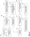
- FIG. 4 illustrates one example flow chart demonstrating a method 200 of evaluating or modeling the effect of particles 76, 78 on an engine 10.
- the method 200 includes receiving at 202 user input 108 or non-user input 110 related to the aforementioned inputs 156, 158, 160, 162, 164, 166.
- the user input 108 or non-user input 110 can include city pairing data 204, that is, flight plan related data, or departure city and frequency data 206.
- the city pairing data 204 or departure city and frequency data 206 can include a set of parameters to be received, selected, or read from the database 116, 216.
- the method 200 can calculate the ground level average dust concentration at 208, according to the parameters, databases 116, 216, and executable computer program.
- the method 200 can then calculate the dust concentration by altitude for each of the set of aforementioned flight phases at 210, according to the parameters, databases 116, 216, and executable computer program.
- the method 200 can calculate an air density for the different flight phases at 213 based on the engine line input 156 and according to the parameters, databases 116, 216, and executable computer program.
- the method 200 can calculate a dust flow at 215 per flight phase according to the parameters, databases 116, 216, and executable computer program.
- the method 200 can then calculate a total dust flow per cycle at 217 according to the parameters, databases 116, 216, and executable computer program.
- the method 200 can then proceed to, respectively, calculate the amount, quantity, or weight of dust entering the engine 10, including, but not limited to, calculating the dust entering the booster per cycle at 218, calculating the total dust entering the booster in the total number of cycles at 220 (based for example, on the number of cycle input 166), calculate the amount, quantity, or weight of dust ingested in the core port variable bleed valve at 222, and/or finally, calculating the total dust exiting the core at 224 after or post the interstage bleed rejection of dust.
- the aforementioned calculated values can be provided in the second portion 154 of the UI 104 or memory 114, 214, and can be provided at the completion of the respective calculating step, or after the completion of all method 200 steps.
- FIG. 5 illustrates another method 300 of evaluating or modeling the effect of particles 76, 78 on an engine 10.
- the method 300 includes selecting at 302 one or more flight paths between two points or a point of departure and frequency of departure in the flight path from the point for at least one aircraft engine 10, wherein the flight path has at least two phases and a flight along the flight path or a departure constitutes one cycle.
- the method 300 can then determine at 304 an average dust concentration value for the two points or the point or departure at ground level, followed by determining 306 an average dust concentration value for each phase of the flight path.
- the method 300 can continue by determining at 308 an air density for the at least one aircraft engine 10 at each phase of the flight path.
- the method 300 can determine at 310 the dust flow through the at least one aircraft engine 10 per cycle based on the average dust concentration values and the air density. After the various calculations have been performed, the method 300 can provide the calculated or determined values to at least one of the maintenance scheduling system 130 or the flight scheduling system 140 to, respectively, adjust or schedule service at 312 of the at least one aircraft engine 10 based on the dust flow. For example, the method 300 can adjust the maintenance schedule or flight schedule, by way of the respective maintenance scheduling system 130 or flight scheduling system 140, based on the method results.
- an optional method 200, 300 step can include determining a dust type for the flight path, based on the dust database input 162, the dust type input 164, the city pairing data 204, the departure city and frequency data 206, or the parameters of the database 116, 216.
- the embodiments disclosed herein provide a method and non-claimed system for evaluating or modeling the effect of dust on an engine.
- the technical effect is that the above described embodiments enable adjusting or scheduling of service, such as flight service or maintenance service, based on the evaluated or modeled effects.
- One advantage that can be realized in the above embodiments is that the above described embodiments can enable accelerated learning on regional or particle-based environmental challenges experienced by engines.
- Another advantage can include identifying or addressing engine problems prior to or earlier than conventional systems or methods, resulting in reduced maintenance or service operations, reduced downtime for the engine, and the like.
- Yet another advantage can include testing or evaluation the particle robustness of engines prior to installation or operation of the engines, or to evaluate or model the expected maintenance or service costs associated therewith.
Landscapes
- Engineering & Computer Science (AREA)
- Business, Economics & Management (AREA)
- Physics & Mathematics (AREA)
- General Physics & Mathematics (AREA)
- Human Resources & Organizations (AREA)
- Theoretical Computer Science (AREA)
- Strategic Management (AREA)
- Entrepreneurship & Innovation (AREA)
- Economics (AREA)
- Quality & Reliability (AREA)
- Tourism & Hospitality (AREA)
- Combustion & Propulsion (AREA)
- Chemical & Material Sciences (AREA)
- General Business, Economics & Management (AREA)
- Operations Research (AREA)
- General Engineering & Computer Science (AREA)
- Marketing (AREA)
- Geometry (AREA)
- Automation & Control Theory (AREA)
- Aviation & Aerospace Engineering (AREA)
- Mechanical Engineering (AREA)
- Computer Hardware Design (AREA)
- Development Economics (AREA)
- Evolutionary Computation (AREA)
- Educational Administration (AREA)
- Game Theory and Decision Science (AREA)
- Pure & Applied Mathematics (AREA)
- Mathematical Optimization (AREA)
- Mathematical Analysis (AREA)
- Computational Mathematics (AREA)
- Testing Of Engines (AREA)
- Structures Of Non-Positive Displacement Pumps (AREA)
- Traffic Control Systems (AREA)
Description
- Turbine engines, and particularly gas or combustion turbine engines, are rotary engines that extract energy from a flow of combusted gases passing through the engine onto a multitude of turbine blades. Gas turbine engines have been used for land and nautical locomotion and power generation, but are most commonly used for aeronautical applications such as for aircraft, including helicopters. In aircraft, gas turbine engines are used for propulsion of the aircraft. In terrestrial applications, turbine engines are often used for power generation.
- Particles, such as dirt, dust, sand, volcanic ash, and other environmental contaminants can cause reduced operational time or "time-on-wing" for the aircraft environment, or reduced "up time" in terrestrial application. This problem is exacerbated in certain operating environments around the globe where turbine engines are exposed to significant amounts of airborne particles. Particles supplied to the turbine components can clog, obstruct, or coat the flow passages and surfaces of the components, which can reduce the lifespan of the components.
-
EP 2562701 A1 relates to an asset operation health monitoring system, in which a plurality of sensors are arranged to determine values of asset operation parameters pertaining to an instance of asset operation. - The present invention is defined in the accompanying claims.
Claim 1 defines a method of predicting the effect of particles on aircraft engines. In the following, apparatus and/or methods referred to as embodiments that nevertheless do not fall within the scope of the claims should be understood as examples useful for understanding the invention. - In the drawings:
-
FIG. 1 is a schematic cross-sectional diagram of a prior art gas turbine engine for an aircraft. -
FIG. 2 illustrates an example schematic view of a system for evaluating or modeling the effect of particles on the engine in accordance with various aspects described herein. -
FIG. 3 is a schematic view of a dust load estimator for the system in accordance with various aspects described. -
FIG. 4 is an example a flow chart diagram demonstrating a method of evaluating or modeling the effect of particles on the engine in accordance with various aspects described herein. -
FIG. 5 is another example a flow chart diagram demonstrating a method of evaluating or modeling the effect of particles on the engine in accordance with various aspects described herein. - The described disclosure is directed to a method and system for evaluating or modeling the effect of dust on aircraft engines, and a method of setting a maintenance schedule for an aircraft turbine blade. For purposes of illustration, the present invention will be described with respect to an aircraft gas turbine engine. It will be understood, however, that the invention is not so limited and can have general applicability in nonaircraft applications, such as other mobile applications and non-mobile industrial, commercial, and residential applications wherein dust can have an effect on a device or engine.
- As used herein, the terms "axial" or "axially" refer to a dimension along a longitudinal axis of an engine or along a longitudinal axis of a component disposed within the engine. The term "forward" used in conjunction with "axial" or "axially" refers to moving in a direction toward the engine inlet, or a component being relatively closer to the engine inlet as compared to another component. The term "aft" used in conjunction with "axial" or "axially" refers to a direction toward the rear or outlet of the engine relative to the engine centerline.
- As used herein, the terms "radial" or "radially" refer to a dimension extending between a center longitudinal axis of the engine, an outer engine circumference, or a circular or annular component disposed within the engine. The use of the terms "proximal" or "proximally," either by themselves or in conjunction with the terms "radial" or "radially," refers to moving in a direction toward the center longitudinal axis, or a component being relatively closer to the center longitudinal axis as compared to another component.
- As used herein, the terms "tangential" or "tangentially" refer to a dimension extending perpendicular to a radial line with respect to the longitudinal axis of the engine or the longitudinal axis of a component disposed therein.
- All directional references (e.g., radial, axial, upper, lower, upward, downward, left, right, lateral, front, back, top, bottom, above, below, vertical, horizontal, clockwise, counterclockwise) are only used for identification purposes to aid the reader's understanding of the disclosure, and do not create limitations, particularly as to the position, orientation, or use thereof. Connection references (e.g., attached, coupled, connected, and joined) are to be construed broadly and can include intermediate members between a collection of elements and relative movement between elements unless otherwise indicated. As such, connection references do not necessarily infer that two elements are directly connected and in fixed relation to each other. The exemplary drawings are for purposes of illustration only and the dimensions, positions, order and relative sizes reflected in the drawings attached hereto can vary.
-
FIG. 1 is a schematic cross-sectional diagram of a prior artgas turbine engine 10 for an aircraft, one exemplary environment in which aspects of the disclosure are relevant. Theengine 10 has a generally longitudinally extending axis orcenterline 12 extending forward 14 toaft 16. Theengine 10 includes, in downstream serial flow relationship, afan section 18 including afan 20, acompressor section 22 including a booster or low pressure (LP)compressor 24 and a high pressure (HP)compressor 26, acombustion section 28 including acombustor 30, aturbine section 32 including a HPturbine 34, and aLP turbine 36, and anexhaust section 38. - The
fan section 18 includes afan casing 40 surrounding thefan 20. Thefan 20 includes a plurality offan blades 42 disposed radially about thecenterline 12. The HPcompressor 26, thecombustor 30, and the HPturbine 34 form acore 44 of theengine 10, which generates combustion gases. Thecore 44 is surrounded bycore casing 46, which can be coupled with thefan casing 40. - A HP shaft or
spool 48 disposed coaxially about thecenterline 12 of theengine 10 drivingly connects the HPturbine 34 to the HPcompressor 26. A LP shaft or spool 50, which is disposed coaxially about thecenterline 12 of theengine 10 within the larger diameter annular HPspool 48, drivingly connects theLP turbine 36 to theLP compressor 24 andfan 20. The portions of theengine 10 mounted to and rotating with either or both of thespools 48, 50 are referred to individually or collectively as arotor 51. - The
LP compressor 24 and the HPcompressor 26 respectively include a plurality ofcompressor stages compressor blades 56, 58 rotate relative to a corresponding set ofstatic compressor vanes 60, 62 (also called a nozzle) to compress or pressurize the stream of fluid passing through the stage. In asingle compressor stage multiple compressor blades 56, 58 can be provided in a ring and can extend radially outwardly relative to thecenterline 12, from a blade platform to a blade tip, while the corresponding static compressor vanes 60, 62 are positioned downstream of and adjacent to therotating blades 56, 58. It is noted that the number of blades, vanes, and compressor stages shown inFIG. 1 were selected for illustrative purposes only, and that other numbers are possible. Theblades 56, 58 for a stage of the compressor can be mounted to adisk 53, which is mounted to the corresponding one of the HP andLP spools 48, 50, with each stage having its own disk. Thevanes core casing 46 in a circumferential arrangement about therotor 51. - The HP
turbine 34 and theLP turbine 36 respectively include a plurality ofturbine stages turbine blades static turbine vanes 72, 74 (also called a nozzle) to extract energy from the stream of fluid passing through the stage. In asingle turbine stage multiple turbine blades centerline 12, from a blade platform to a blade tip, while the corresponding static turbine vanes 72, 74 are positioned upstream of and adjacent to the rotatingblades FIG. 1 were selected for illustrative purposes only, and that other numbers are possible. - In operation, the rotating
fan 20 supplies ambient air to theLP compressor 24, which then supplies pressurized ambient air to the HPcompressor 26, which further pressurizes the ambient air. The pressurized air from the HPcompressor 26 is mixed with fuel in thecombustor 30 and ignited, thereby generating combustion gases. Some work is extracted from these gases by the HPturbine 34, which drives the HPcompressor 26. The combustion gases are discharged into theLP turbine 36, which extracts additional work to drive theLP compressor 24, and the exhaust gas is ultimately discharged from theengine 10 via theexhaust section 38. The driving of theLP turbine 36 drives the LP spool 50 to rotate thefan 20 and theLP compressor 24. - Operation of an
engine 10 can be in an environment having particles, such as dirt, dust, sand, volcanic ash, and other environmental contaminants, which can be airborne or ground-based. In one example, a first set ofairborne particles 76 can be drawn, sucked, ingested, or otherwise received by anoperating engine 10. In another example, a second set of ground-basedparticles 78 can be drawn, sucked, or agitated such that they are lifted from the ground, and are further ingested or otherwise received by anoperating engine 10. Theparticles operating engine 10 can have the effect of causing reduced operational time or "time-on-wing" for the aircraft environment, or reduced "up time" in terrestrial application. For example, theparticles engine 10 components, reduce efficiency in combustion, or can clog, obstruct, or coat the flow passages and surfaces of the components, which can further reduce the lifespan of the components. - Different geographic locations of
engine 10 operation can include different types or compositions ofparticles particles particles particles engine 10 on an aircraft at cruise altitude is not likely to ingest or receive the set of ground-basedparticles 78. -
FIG. 2 illustrates asystem 100 for evaluating or modeling the effect ofparticles engine 10. As shown, thesystem 100 can include a terminal 102 having a user interface (UI) 104 and acontroller module 106. TheUI 104 can be configured to receive auser input 108, for example, by way of a computer keyboard, computer mouse, or touch screen device. Alternative to theuser input 108, or in addition to theuser input 108, anon-user input 110 can be received directly by thecontroller module 106. In this sense, theuser input 108 and theuser interface 104, or thenon-user input 110, can be optional. - In another example embodiment, the
non-user input 110 can be received by theUI 104. Additional non-limiting examples of receivinguser input 108 can include voice recognition. Additional non-limiting examples of receivingnon-user input 110 can include receiving sensor output or sensor values, or output from another system. Examples of sensor or another system output can include weather measurements or reading (e.g. humidity, temperature, wind speed, etc.), geographic location sensor outputs, global positioning system outputs, or flight plan values. Theuser input 108 andnon-user input 110 can include or can be related to theparticles engine 10, the geographic location of theengine 10 operation, or anyother inputs - The
system 100 can also optionally include, for example, a distributedcomputing system 120, amaintenance scheduling system 130, aflight scheduler system 140, or a combination thereof. The terminal 102, distributedcomputing system 120,maintenance scheduling system 130, orflight scheduler system 140 can be communicatively interconnected (as illustrated by dotted line), or can be communicatively connected by way of a network, such as a local area network, wide area network, fiber optic network, or the Internet. Additional communicative interconnection examples can be included. - The
controller module 106 can include aprocessor 112 andmemory 114. Thecontroller module 106 orprocessor 112 can also be operably or communicatively coupled to theUI 104 such that information or input received by theUI 104 can be operably read, interpreted, or delivered to thecontroller module 106 orprocessor 112. - The
memory 114 can include non-volatile memory, non-transitory memory, random access memory (RAM), read-only memory (ROM), flash memory, or one or more different types of portable electronic memory, such as discs, DVDs, CD-ROMs, etc., or any suitable combination of these types of memory. Thecontroller module 106 orprocessor 112 can further be configured to run any suitable programs. Non-limiting embodiments of the disclosure can be included wherein, for example, thecontroller module 106 orprocessor 112 can also be connected with other controllers, processors, or systems of the aircraft, or can be included as part of or a subcomponent of another controller, processor, or system of the aircraft. - A computer
searchable database 116 of information can be stored in thememory 114 and accessible by thecontroller module 106 orprocessor 112. Embodiments of the disclosure can be included wherein the computersearchable database 116 can include a set of parameters related toparticles engine 10 can be exposed to. Non-limiting examples of thedatabase 116 set of parameters can include particle or dust types, particle compositions, particle ratios relative to various types or compositions, particle concentration values, averages related to the aforementioned parameters, high or low expected values or ranges for the aforementioned parameters, or a combination thereof. In one example, a high value or range of the aforementioned parameters can include expectedparticle database 116 can also or alternatively include the aforementioned parameter values as related to artificial particle or synthetic particle (i.e. synthetic dust). In yet another non-limiting examples of thedatabase 116, embodiments of the disclosure can includeparticle - The
controller module 106 orprocessor 112 can run a set of executable instructions to display thedatabase 116, for example on theUI 104, or otherwise access thedatabase 116. It will be understood that thedatabase 116 can be anysuitable database 116, including asingle database 116 having multiple sets of data, multiplediscrete databases 116 linked together, or even a simple table of data. It is contemplated that thedatabase 116 can incorporate a number ofdatabases 116 or that thedatabase 116 can actually be a number ofseparate databases 116. Thedatabase 116 can store data that can include, among other things, historical data related to theaforementioned particle engine 10, aircraft, or related to a fleet of aircraft. Thedatabase 116 can also include reference values including historic values or aggregated values. - Non-limiting embodiments of the disclosure can include configurations wherein, for example the distributing
computer system 130 includes a set ofprocessors 212, at least amemory 214, or adatabase 216, which can be similar to the aforementioned corresponding components of thecontroller module 106. In this example, the distributedcomputing system 120 can be configured to perform a set of processing or computing functions related to, or in place of the computing functions of thecontroller module 106. In this sense, thecontroller module 106 can be configured to execute a portion of the computer program, and to communicate with the distributedcomputing system 120, wherein a more complex, powerful, or resource intensive portion of the computer program can be executed to generate the output described below. The distributedcomputing system 120components corresponding controller module 106components - One of the
controller module 106 orprocessor particles engine 10. The program can include a computer program product that can include machine-readable media for carrying or having machine-executable instructions or data structures stored thereon. Such machine-readable media can be any available media, which can be accessed by a general purpose or special purpose computer or other machine with a processor. Generally, such a computer program can include routines, programs, objects, components, data structures, and the like, that have the technical effect of performing particular tasks or implementing particular abstract data types. Machine-executable instructions, associated data structures, and programs represent examples of program code for executing the exchange of information as disclosed herein. Machine-executable instructions can include, for example, instructions and data, which cause a generalpurpose computer, special purpose computer, or special purpose processing machine to perform a certain function or group of functions. - The
maintenance scheduling system 130 can include any system configured to receive an input, and in response to the input, generate or schedule maintenance actions or services for anengine 10, aircraft, or fleet ofengines 10 or aircraft. Likewise, in embodiments of the disclosure wherein theengine 10 is anaircraft engine 10, theflight scheduling system 140 can include any system configured to receive an input, and in response to the input, generate or schedule flight actions, services, flight plans, route information, and the like for an aircraft or a fleet of aircraft. In this sense, themaintenance scheduling system 130 andflight scheduling system 140 can be response to data or information processed, generated, or provided by the terminal 102, the distributedcomputing system 120,controller module 106, orprocessor - During operation of the
engine 10 in anenvironment having particles particles engine 10, a portion of the dust orparticles engine 10 can be removed or ejected from theengine 10 by way of a set of ports, including but not limited to the compressor bleed ports, or ejected from theengine 10 in exhaust. Thesystem 100 illustrated can be used to evaluate or model the effect of dust orparticles engine 10, and in response to the evaluation or modeling, scheduling or adjust at least one of maintenance services, flight scheduling, or the like, for theengine 10. While maintenance services or flight scheduling is described, embodiments of the disclosure can be included to estimate or predict the current or future effects on theengine 10 or aircraft fleet, based upon, for example, a history of aparticular engine 10, or history of a subset of the fleet with similar flight paths or regions or cities. Embodiments of the disclosure can also be included to estimate or predict the current or future effects on theengine 10 or aircraft fleet, based upon engine operational parameters such as thrust, fuel consumption, flow rates, pressures, and temperatures. The estimations or prediction of the effects on theengine 10 can be applicable beyond maintenance services, flight scheduling, or the like, including but not limited to estimating or predicting time-on-wing, or "life" of theengine 10. -
FIG. 3 illustrates a schematic view of adust load estimator 150 for dust load estimation of anengine 10, wherein theestimator 150 includes afirst portion 152 configured to receive a set of input values and asecond portion 154 configured to provide a set of output values. Thedust load estimator 150 can be included in theUI 104, or can be a representation of a portion of data stored inmemory dust load estimator 150 is illustrated as a user-interactive view, embodiments of the disclosure can be included wherein thedust load estimator 150 does not have a directly interactive user interface. - The
first portion 152 can be configured to provide or receive inputs from theuser input 108 ornon-user input 110. Non-limiting examples of inputs can include anengine line 156 orengine 10 type, ageographic region 158 where theengine 10 is, will be, or is estimated to be operated in, anoperator 160 of the engine, such as the airline operator, maintenance operator, or client operator, a particle ordust database 162, a particle ordust type 164, a number ofengine 10 cycles fordust load calculation 166 or estimating, or a combination thereof. At least a subset of theaforementioned inputs database system 100, and can prompt the user orsystem 100 for correction prior to dust load estimation. - The
second portion 154 can be configured to generate, compute, or operably receive a set of outputs based on the dust load estimation. Thesecond portion 154 can display the outputs for user review, or can save the output values, to be provided to themaintenance scheduling system 130 or theflight scheduling system 140. As previously mentioned, the generating, computing, or operably receiving the set of outputs can be performed by thecontroller module 106 or the distributedcomputing system 120. - Non-limiting examples of dust load output values can include a fan booster split
streamline value 168, an engine coretotal value 170, a variablebleed valve value 172, a set ofvalues 174 related to a set of flight phases, a compressor bleedsvalue 176, a high pressurecompressor exit value 178, a dust splits forcombustor system value 180, and a dust splits for turbine system value. Examples of the set ofvalues 174 related to the set of flight phases dust split can include, but is not limited to, a taxi and ground idle (GI)value 184, aclimb value 188, adescent value 190, anapproach value 192, and a thrust reverse (TR)value 194. At least a subset of thesecond portion 154 of output values can be provided or outputted in a weight measurement of a dust load experienced per 1000 cycles (e.g. per 1000 flights), wherein the weight measurement is, for example, measured in kilograms or pounds. Alternative embodiments of the disclosure can include configurations wherein the output values can be provided or outputted in non-weight measurements, including volumes, ratios, percentages, and the like. - The fan booster split
streamline value 168 can include a value related to or indicating an amount of dust orparticles fan 20 of theengine 10, and a value or indication of dust that bypasses theengine core 44 as opposed to ingested by theengine core 44. The coretotal value 170 can include a value related to or indicating an amount of dust orparticles engine core 44 through theLP compressor 24. Similarly, the a variablebleed valve value 172, compressor bleedsvalue 176, or high pressurecompressor exit value 178 can include a respective value related to or indicating an amount of dust orparticles core 44. The set ofvalues 174 related to the set of flight phases can include a value related to or indicating an amount of dust orparticles combustor system value 180 and the dust splits forturbine system value 182 can include a respective value related to or indicating an amount of dust orparticles turbine sections -
FIG. 4 illustrates one example flow chart demonstrating amethod 200 of evaluating or modeling the effect ofparticles engine 10. Themethod 200 includes receiving at 202user input 108 ornon-user input 110 related to theaforementioned inputs user input 108 ornon-user input 110 can includecity pairing data 204, that is, flight plan related data, or departure city andfrequency data 206. Thecity pairing data 204 or departure city andfrequency data 206 can include a set of parameters to be received, selected, or read from thedatabase method 200 can calculate the ground level average dust concentration at 208, according to the parameters,databases method 200 can then calculate the dust concentration by altitude for each of the set of aforementioned flight phases at 210, according to the parameters,databases - Following
step 210, themethod 200 can calculate an air density for the different flight phases at 213 based on theengine line input 156 and according to the parameters,databases method 200 can calculate a dust flow at 215 per flight phase according to the parameters,databases method 200 can then calculate a total dust flow per cycle at 217 according to the parameters,databases method 200 can then proceed to, respectively, calculate the amount, quantity, or weight of dust entering theengine 10, including, but not limited to, calculating the dust entering the booster per cycle at 218, calculating the total dust entering the booster in the total number of cycles at 220 (based for example, on the number of cycle input 166), calculate the amount, quantity, or weight of dust ingested in the core port variable bleed valve at 222, and/or finally, calculating the total dust exiting the core at 224 after or post the interstage bleed rejection of dust. The aforementioned calculated values can be provided in thesecond portion 154 of theUI 104 ormemory method 200 steps. -
FIG. 5 illustrates anothermethod 300 of evaluating or modeling the effect ofparticles engine 10. Themethod 300 includes selecting at 302 one or more flight paths between two points or a point of departure and frequency of departure in the flight path from the point for at least oneaircraft engine 10, wherein the flight path has at least two phases and a flight along the flight path or a departure constitutes one cycle. Themethod 300 can then determine at 304 an average dust concentration value for the two points or the point or departure at ground level, followed by determining 306 an average dust concentration value for each phase of the flight path. Themethod 300 can continue by determining at 308 an air density for the at least oneaircraft engine 10 at each phase of the flight path. Next themethod 300 can determine at 310 the dust flow through the at least oneaircraft engine 10 per cycle based on the average dust concentration values and the air density. After the various calculations have been performed, themethod 300 can provide the calculated or determined values to at least one of themaintenance scheduling system 130 or theflight scheduling system 140 to, respectively, adjust or schedule service at 312 of the at least oneaircraft engine 10 based on the dust flow. For example, themethod 300 can adjust the maintenance schedule or flight schedule, by way of the respectivemaintenance scheduling system 130 orflight scheduling system 140, based on the method results. - The sequences depicted are for illustrative purposes only and are not meant to limit the
methods methods methods optional method dust database input 162, thedust type input 164, thecity pairing data 204, the departure city andfrequency data 206, or the parameters of thedatabase - Additionally, the design and placement of the various components can be rearranged such that a number of different in-line configurations could be realized.
- The embodiments disclosed herein provide a method and non-claimed system for evaluating or modeling the effect of dust on an engine. The technical effect is that the above described embodiments enable adjusting or scheduling of service, such as flight service or maintenance service, based on the evaluated or modeled effects. One advantage that can be realized in the above embodiments is that the above described embodiments can enable accelerated learning on regional or particle-based environmental challenges experienced by engines. Another advantage can include identifying or addressing engine problems prior to or earlier than conventional systems or methods, resulting in reduced maintenance or service operations, reduced downtime for the engine, and the like. Yet another advantage can include testing or evaluation the particle robustness of engines prior to installation or operation of the engines, or to evaluate or model the expected maintenance or service costs associated therewith.
- To the extent not already described, the different features and structures of the various embodiments can be used in combination with each other as desired. That one feature cannot be illustrated in all of the embodiments is not meant to be construed that it cannot be, but is done for brevity of description. Thus, the various features of the different embodiments can be mixed and matched as desired to form new embodiments, whether or not the new embodiments are expressly described. Moreover, while "a set of" various elements have been described, it will be understood that "a set" can include any number of the respective elements, including only one element. Combinations or permutations of features described herein are covered by this disclosure.
Claims (7)
- A method of predicting the effect of particles on aircraft engines (10), comprising:for at least one aircraft engine (10), determining (208, 304), by a processor of a system (100), an average particle concentration value for two points, said two points defining a flight path therebetween, said flight path defining one cycle;determining (210, 306) an average particle concentration value for each phase of the flight path;characterized bydetermining (213, 308) an air density for the at least one aircraft engine (10) at each phase of the flight path;determining (217, 310) particle flow through the at least one aircraft engine (10) per cycle based on the average particle concentration values and the air density; andpredicting (312) at least one of current or future effects on the at least one aircraft engine (10) based on the particle flow,the method further including:the step of scheduling services for the at least one aircraft engine (10) based on the predicted at least one of current or future effects on the at least one aircraft engine (10); and/orthe step of scheduling actions for the at least one aircraft engine (10) based on the predicted at least one of current or future effects on the at least one aircraft engine (10).
- The method of claim 1, wherein scheduling actions for the at least one aircraft engine (10) includes at least one of maintenance actions or flight actions.
- The method of any preceding claim, wherein predicting at least one of current or future effects on the at least one aircraft engine (10) includes predicting a time-on-wing for the at least one aircraft engine (10).
- The method of any preceding claim, wherein predicting at least one of current or future effects on the at least one aircraft engine (10) includes predicting an operational life for the at least one aircraft engine (10).
- The method of any preceding claim, wherein the flight path has at least two phases and a flight along the flight path constitutes the one cycle.
- The method of any preceding claim, further comprising determining particle flow through individual components of the at least one aircraft engine (10).
- The method of any preceding claim, wherein the determining the particle concentration value further comprises determining at least one of a dust particle composition, a dust particle ratio, a dust particle concentration value, an average dust particle composition, or a range of dust particle composition.
Applications Claiming Priority (2)
| Application Number | Priority Date | Filing Date | Title |
|---|---|---|---|
| US15/009,894 US9718562B1 (en) | 2016-01-29 | 2016-01-29 | System and method of evaluating the effect of dust on aircraft engines |
| EP17153369.8A EP3200039B1 (en) | 2016-01-29 | 2017-01-26 | System and method of evaluating the effect of dust on aircraft engines |
Related Parent Applications (1)
| Application Number | Title | Priority Date | Filing Date |
|---|---|---|---|
| EP17153369.8A Division EP3200039B1 (en) | 2016-01-29 | 2017-01-26 | System and method of evaluating the effect of dust on aircraft engines |
Publications (2)
| Publication Number | Publication Date |
|---|---|
| EP3709114A1 EP3709114A1 (en) | 2020-09-16 |
| EP3709114B1 true EP3709114B1 (en) | 2023-08-16 |
Family
ID=58347038
Family Applications (2)
| Application Number | Title | Priority Date | Filing Date |
|---|---|---|---|
| EP17153369.8A Active EP3200039B1 (en) | 2016-01-29 | 2017-01-26 | System and method of evaluating the effect of dust on aircraft engines |
| EP20159148.4A Active EP3709114B1 (en) | 2016-01-29 | 2017-01-26 | Method of predicting the effect of particles on aircraft engines |
Family Applications Before (1)
| Application Number | Title | Priority Date | Filing Date |
|---|---|---|---|
| EP17153369.8A Active EP3200039B1 (en) | 2016-01-29 | 2017-01-26 | System and method of evaluating the effect of dust on aircraft engines |
Country Status (5)
| Country | Link |
|---|---|
| US (1) | US9718562B1 (en) |
| EP (2) | EP3200039B1 (en) |
| JP (2) | JP6938075B2 (en) |
| CN (1) | CN107025327B (en) |
| CA (1) | CA2955424C (en) |
Families Citing this family (8)
| Publication number | Priority date | Publication date | Assignee | Title |
|---|---|---|---|---|
| GB2577065A (en) * | 2018-09-11 | 2020-03-18 | Satavia Ltd | System and method for aircraft health and schedule maintenance |
| GB2577064B (en) | 2018-09-11 | 2021-03-24 | Satavia Ltd | System and method for aircraft flight planning |
| US11125168B2 (en) * | 2018-10-24 | 2021-09-21 | Raytheon Technologies Corporation | Dirt mitigation in a gas turbine engine |
| US11261800B2 (en) | 2018-10-24 | 2022-03-01 | Raytheon Technologies Corporation | Adaptive bleed schedule in a gas turbine engine |
| US10692388B1 (en) * | 2018-12-14 | 2020-06-23 | General Electric Company | Global environmental data and application methods for understanding engine health and maintenance |
| US12106235B2 (en) | 2019-03-21 | 2024-10-01 | Rtx Corporation | System for forecasting aircraft engine deterioration using recurrent neural networks |
| US12135549B2 (en) * | 2022-02-10 | 2024-11-05 | General Electric Company | Systems and methods for providing information regarding particulate matter within an aircraft engine |
| GB202208601D0 (en) * | 2022-06-13 | 2022-07-27 | Rolls Royce Plc | Maintenance management of a propulsion system |
Family Cites Families (23)
| Publication number | Priority date | Publication date | Assignee | Title |
|---|---|---|---|---|
| US5070722A (en) * | 1990-09-21 | 1991-12-10 | United Technologies Corporation | Turbine engine debris ingestion monitor |
| US5491642A (en) | 1993-12-03 | 1996-02-13 | United Technologies Corporation | CCD based particle image direction and zero velocity resolver |
| DE19702849C2 (en) | 1997-01-27 | 2000-05-18 | Deutsch Zentr Luft & Raumfahrt | Method for determining the mass flow distribution of a flow over a plane |
| DE19963393C1 (en) | 1999-12-28 | 2001-07-26 | Bosch Gmbh Robert | Flow analysis method and apparatus |
| TW466346B (en) | 2001-03-05 | 2001-12-01 | Nat Science Council | A low-cost continuous-wave-laser (CW laser) digital particle image velocimetry |
| US6940888B2 (en) | 2002-11-21 | 2005-09-06 | New Wave Research | Dual head laser system with intra-cavity polarization, and particle image velocimetry system using same |
| US7200538B2 (en) * | 2003-01-15 | 2007-04-03 | General Electric Company | Methods and apparatus for modeling gas turbine engines |
| EP1686357B1 (en) | 2005-01-31 | 2008-07-23 | Maillefer S.A. | Device for measuring a mass flow rate of a particulate material |
| US7383131B1 (en) * | 2006-09-27 | 2008-06-03 | Rockwell Collins, Inc. | Airborne volcanic ash cloud and eruption detection system and method |
| US7880883B2 (en) | 2007-10-12 | 2011-02-01 | Interactive Flow Studies Corporation | Fluid flow computation, visualization, and analysis |
| US8204671B2 (en) * | 2009-05-18 | 2012-06-19 | United Technologies Corporation | System and method of estimating gas turbine engine performance |
| US8074498B2 (en) * | 2009-05-18 | 2011-12-13 | United Technologies Corporation | System and method of assessing thermal energy levels of a gas turbine engine component |
| CN101567024B (en) * | 2009-05-21 | 2010-12-01 | 北京航空航天大学 | A compressor time-advancing flow method considering air system air source bleed air |
| JP5452271B2 (en) | 2010-02-12 | 2014-03-26 | 日本碍子株式会社 | Fluid observation method and fluid for flow observation |
| FR2971595B1 (en) * | 2011-02-15 | 2013-03-22 | Snecma | MONITORING AN AIRCRAFT ENGINE TO ANTICIPATE MAINTENANCE OPERATIONS |
| GB2493932A (en) * | 2011-08-23 | 2013-02-27 | Rolls Royce Plc | Method Of Managing Operational Health Of Assets |
| US8764414B2 (en) * | 2011-11-07 | 2014-07-01 | Bha Altair, Llc | System for detecting contaminants in an intake flow of a compressor |
| US9436784B2 (en) * | 2013-02-08 | 2016-09-06 | University Of Alaska Fairbanks | Validating and calibrating a forecast model |
| PL3041743T3 (en) * | 2013-09-06 | 2020-06-29 | Ge Aviation Systems Llc | Aircraft and particulate detection method |
| US20150121888A1 (en) * | 2013-11-05 | 2015-05-07 | General Electric Company | Gas turbine online wash control |
| CN103625652A (en) * | 2013-11-28 | 2014-03-12 | 陕西飞机工业(集团)有限公司 | Aircraft body surface temporary protection method used on the way of aircraft ferry flights |
| CN104615849B (en) * | 2014-12-30 | 2017-07-11 | 中国民航大学 | A kind of flight plan assessment system and implementation method suitable for General Aviation |
| CN105279334B (en) * | 2015-10-29 | 2018-06-05 | 天津大学 | Particulate matter settling amount evaluation method in aircraft loop system based on general simplified model |
-
2016
- 2016-01-29 US US15/009,894 patent/US9718562B1/en active Active
-
2017
- 2017-01-18 JP JP2017006380A patent/JP6938075B2/en active Active
- 2017-01-19 CA CA2955424A patent/CA2955424C/en active Active
- 2017-01-25 CN CN201710055905.2A patent/CN107025327B/en active Active
- 2017-01-26 EP EP17153369.8A patent/EP3200039B1/en active Active
- 2017-01-26 EP EP20159148.4A patent/EP3709114B1/en active Active
-
2021
- 2021-08-24 JP JP2021136290A patent/JP2022000580A/en not_active Ceased
Also Published As
| Publication number | Publication date |
|---|---|
| EP3709114A1 (en) | 2020-09-16 |
| EP3200039B1 (en) | 2020-02-26 |
| JP2017137859A (en) | 2017-08-10 |
| JP6938075B2 (en) | 2021-09-22 |
| US9718562B1 (en) | 2017-08-01 |
| CA2955424A1 (en) | 2017-07-29 |
| CN107025327B (en) | 2021-11-23 |
| CA2955424C (en) | 2025-07-08 |
| JP2022000580A (en) | 2022-01-04 |
| US20170217606A1 (en) | 2017-08-03 |
| CN107025327A (en) | 2017-08-08 |
| EP3200039A1 (en) | 2017-08-02 |
Similar Documents
| Publication | Publication Date | Title |
|---|---|---|
| EP3200039B1 (en) | System and method of evaluating the effect of dust on aircraft engines | |
| US10496086B2 (en) | Gas turbine engine fleet performance deterioration | |
| CN109766566B (en) | Apparatus, method, and storage medium to improve operation of a turbine engine | |
| EP2078995B1 (en) | A method of monitoring a gas turbine engine | |
| CN106777554B (en) | State baseline-based health state evaluation method for air circuit unit body of aero-engine | |
| US20090048730A1 (en) | Method and system for planning repair of an engine | |
| US20180266269A1 (en) | Method and System for Identifying Rub Events | |
| EP3451085B1 (en) | Method for selection of optimal engine operating conditions for generating linearized models for on-board control and estimation | |
| EP3352034A1 (en) | Classification of gas turbine engine components | |
| US20140150550A1 (en) | Method and system for integrating gas turbine trim balancing system into electronic engine controls | |
| EP3712737A1 (en) | Signal response monitoring for turbine engines | |
| US20230251651A1 (en) | Systems and methods for providing information regarding particulate matter within an aircraft engine | |
| US11952149B2 (en) | System and method of forecasting aircraft engine operational data for predictive analytics | |
| Schnell et al. | Integration-and intake-induced flow distortions and their impact on aerodynamic fan performance | |
| US12241382B2 (en) | Vibration response reduction for aircraft engines | |
| EP3828420B1 (en) | Flow machine performance map modelling based on correlation with exit mass flow, data carrier and system for analysing flow machine behaviour | |
| Akhmedzyanov et al. | Automated selection of the material a fan blade PS-90A | |
| Venediger | Civil aircraft trajectory analyses-impact of engine degradation on fuel burn and emissions | |
| CN115638051B (en) | Reducing the vibration response of aircraft engines | |
| KR101409361B1 (en) | Method for modeling engine performance for aircraft | |
| Camilleri | An assessment of high overall pressure ratio intercooled engines for civil aviation | |
| Silva | Turbofan Engine Behaviour Forecasting using Flight Data and Machine Learning Methods | |
| Schlette et al. | Preliminary Design and Analysis of Supersonic Business Jet Engines. Aerospace 2022, 9, 493 | |
| e Silva | Flight Data Tools Applied to Engine Health Monitoring | |
| Kyung et al. | A qualitative evaluation method for engine and its operating-envelope using GSP (Gas turbine Simulation Program) |
Legal Events
| Date | Code | Title | Description |
|---|---|---|---|
| PUAI | Public reference made under article 153(3) epc to a published international application that has entered the european phase |
Free format text: ORIGINAL CODE: 0009012 |
|
| STAA | Information on the status of an ep patent application or granted ep patent |
Free format text: STATUS: THE APPLICATION HAS BEEN PUBLISHED |
|
| AC | Divisional application: reference to earlier application |
Ref document number: 3200039 Country of ref document: EP Kind code of ref document: P |
|
| AK | Designated contracting states |
Kind code of ref document: A1 Designated state(s): AL AT BE BG CH CY CZ DE DK EE ES FI FR GB GR HR HU IE IS IT LI LT LU LV MC MK MT NL NO PL PT RO RS SE SI SK SM TR |
|
| STAA | Information on the status of an ep patent application or granted ep patent |
Free format text: STATUS: REQUEST FOR EXAMINATION WAS MADE |
|
| 17P | Request for examination filed |
Effective date: 20210303 |
|
| RBV | Designated contracting states (corrected) |
Designated state(s): AL AT BE BG CH CY CZ DE DK EE ES FI FR GB GR HR HU IE IS IT LI LT LU LV MC MK MT NL NO PL PT RO RS SE SI SK SM TR |
|
| STAA | Information on the status of an ep patent application or granted ep patent |
Free format text: STATUS: EXAMINATION IS IN PROGRESS |
|
| 17Q | First examination report despatched |
Effective date: 20211215 |
|
| RIC1 | Information provided on ipc code assigned before grant |
Ipc: G07C 5/08 20060101ALI20230202BHEP Ipc: G07C 5/00 20060101ALI20230202BHEP Ipc: F02C 9/00 20060101ALI20230202BHEP Ipc: G06Q 10/0631 20230101ALI20230202BHEP Ipc: G06Q 10/20 20230101ALI20230202BHEP Ipc: G05B 23/02 20060101AFI20230202BHEP |
|
| GRAP | Despatch of communication of intention to grant a patent |
Free format text: ORIGINAL CODE: EPIDOSNIGR1 |
|
| STAA | Information on the status of an ep patent application or granted ep patent |
Free format text: STATUS: GRANT OF PATENT IS INTENDED |
|
| INTG | Intention to grant announced |
Effective date: 20230310 |
|
| GRAS | Grant fee paid |
Free format text: ORIGINAL CODE: EPIDOSNIGR3 |
|
| GRAA | (expected) grant |
Free format text: ORIGINAL CODE: 0009210 |
|
| STAA | Information on the status of an ep patent application or granted ep patent |
Free format text: STATUS: THE PATENT HAS BEEN GRANTED |
|
| AC | Divisional application: reference to earlier application |
Ref document number: 3200039 Country of ref document: EP Kind code of ref document: P |
|
| AK | Designated contracting states |
Kind code of ref document: B1 Designated state(s): AL AT BE BG CH CY CZ DE DK EE ES FI FR GB GR HR HU IE IS IT LI LT LU LV MC MK MT NL NO PL PT RO RS SE SI SK SM TR |
|
| P01 | Opt-out of the competence of the unified patent court (upc) registered |
Effective date: 20230724 |
|
| REG | Reference to a national code |
Ref country code: CH Ref legal event code: EP |
|
| REG | Reference to a national code |
Ref country code: DE Ref legal event code: R096 Ref document number: 602017072975 Country of ref document: DE |
|
| REG | Reference to a national code |
Ref country code: IE Ref legal event code: FG4D |
|
| REG | Reference to a national code |
Ref country code: LT Ref legal event code: MG9D |
|
| REG | Reference to a national code |
Ref country code: NL Ref legal event code: MP Effective date: 20230816 |
|
| REG | Reference to a national code |
Ref country code: AT Ref legal event code: MK05 Ref document number: 1600671 Country of ref document: AT Kind code of ref document: T Effective date: 20230816 |
|
| PG25 | Lapsed in a contracting state [announced via postgrant information from national office to epo] |
Ref country code: GR Free format text: LAPSE BECAUSE OF FAILURE TO SUBMIT A TRANSLATION OF THE DESCRIPTION OR TO PAY THE FEE WITHIN THE PRESCRIBED TIME-LIMIT Effective date: 20231117 |
|
| PG25 | Lapsed in a contracting state [announced via postgrant information from national office to epo] |
Ref country code: IS Free format text: LAPSE BECAUSE OF FAILURE TO SUBMIT A TRANSLATION OF THE DESCRIPTION OR TO PAY THE FEE WITHIN THE PRESCRIBED TIME-LIMIT Effective date: 20231216 |
|
| PG25 | Lapsed in a contracting state [announced via postgrant information from national office to epo] |
Ref country code: SE Free format text: LAPSE BECAUSE OF FAILURE TO SUBMIT A TRANSLATION OF THE DESCRIPTION OR TO PAY THE FEE WITHIN THE PRESCRIBED TIME-LIMIT Effective date: 20230816 Ref country code: RS Free format text: LAPSE BECAUSE OF FAILURE TO SUBMIT A TRANSLATION OF THE DESCRIPTION OR TO PAY THE FEE WITHIN THE PRESCRIBED TIME-LIMIT Effective date: 20230816 Ref country code: PT Free format text: LAPSE BECAUSE OF FAILURE TO SUBMIT A TRANSLATION OF THE DESCRIPTION OR TO PAY THE FEE WITHIN THE PRESCRIBED TIME-LIMIT Effective date: 20231218 Ref country code: NO Free format text: LAPSE BECAUSE OF FAILURE TO SUBMIT A TRANSLATION OF THE DESCRIPTION OR TO PAY THE FEE WITHIN THE PRESCRIBED TIME-LIMIT Effective date: 20231116 Ref country code: NL Free format text: LAPSE BECAUSE OF FAILURE TO SUBMIT A TRANSLATION OF THE DESCRIPTION OR TO PAY THE FEE WITHIN THE PRESCRIBED TIME-LIMIT Effective date: 20230816 Ref country code: LV Free format text: LAPSE BECAUSE OF FAILURE TO SUBMIT A TRANSLATION OF THE DESCRIPTION OR TO PAY THE FEE WITHIN THE PRESCRIBED TIME-LIMIT Effective date: 20230816 Ref country code: LT Free format text: LAPSE BECAUSE OF FAILURE TO SUBMIT A TRANSLATION OF THE DESCRIPTION OR TO PAY THE FEE WITHIN THE PRESCRIBED TIME-LIMIT Effective date: 20230816 Ref country code: IS Free format text: LAPSE BECAUSE OF FAILURE TO SUBMIT A TRANSLATION OF THE DESCRIPTION OR TO PAY THE FEE WITHIN THE PRESCRIBED TIME-LIMIT Effective date: 20231216 Ref country code: HR Free format text: LAPSE BECAUSE OF FAILURE TO SUBMIT A TRANSLATION OF THE DESCRIPTION OR TO PAY THE FEE WITHIN THE PRESCRIBED TIME-LIMIT Effective date: 20230816 Ref country code: GR Free format text: LAPSE BECAUSE OF FAILURE TO SUBMIT A TRANSLATION OF THE DESCRIPTION OR TO PAY THE FEE WITHIN THE PRESCRIBED TIME-LIMIT Effective date: 20231117 Ref country code: FI Free format text: LAPSE BECAUSE OF FAILURE TO SUBMIT A TRANSLATION OF THE DESCRIPTION OR TO PAY THE FEE WITHIN THE PRESCRIBED TIME-LIMIT Effective date: 20230816 Ref country code: AT Free format text: LAPSE BECAUSE OF FAILURE TO SUBMIT A TRANSLATION OF THE DESCRIPTION OR TO PAY THE FEE WITHIN THE PRESCRIBED TIME-LIMIT Effective date: 20230816 |
|
| PG25 | Lapsed in a contracting state [announced via postgrant information from national office to epo] |
Ref country code: PL Free format text: LAPSE BECAUSE OF FAILURE TO SUBMIT A TRANSLATION OF THE DESCRIPTION OR TO PAY THE FEE WITHIN THE PRESCRIBED TIME-LIMIT Effective date: 20230816 |
|
| PG25 | Lapsed in a contracting state [announced via postgrant information from national office to epo] |
Ref country code: ES Free format text: LAPSE BECAUSE OF FAILURE TO SUBMIT A TRANSLATION OF THE DESCRIPTION OR TO PAY THE FEE WITHIN THE PRESCRIBED TIME-LIMIT Effective date: 20230816 |
|
| PG25 | Lapsed in a contracting state [announced via postgrant information from national office to epo] |
Ref country code: SM Free format text: LAPSE BECAUSE OF FAILURE TO SUBMIT A TRANSLATION OF THE DESCRIPTION OR TO PAY THE FEE WITHIN THE PRESCRIBED TIME-LIMIT Effective date: 20230816 Ref country code: RO Free format text: LAPSE BECAUSE OF FAILURE TO SUBMIT A TRANSLATION OF THE DESCRIPTION OR TO PAY THE FEE WITHIN THE PRESCRIBED TIME-LIMIT Effective date: 20230816 Ref country code: ES Free format text: LAPSE BECAUSE OF FAILURE TO SUBMIT A TRANSLATION OF THE DESCRIPTION OR TO PAY THE FEE WITHIN THE PRESCRIBED TIME-LIMIT Effective date: 20230816 Ref country code: EE Free format text: LAPSE BECAUSE OF FAILURE TO SUBMIT A TRANSLATION OF THE DESCRIPTION OR TO PAY THE FEE WITHIN THE PRESCRIBED TIME-LIMIT Effective date: 20230816 Ref country code: DK Free format text: LAPSE BECAUSE OF FAILURE TO SUBMIT A TRANSLATION OF THE DESCRIPTION OR TO PAY THE FEE WITHIN THE PRESCRIBED TIME-LIMIT Effective date: 20230816 Ref country code: CZ Free format text: LAPSE BECAUSE OF FAILURE TO SUBMIT A TRANSLATION OF THE DESCRIPTION OR TO PAY THE FEE WITHIN THE PRESCRIBED TIME-LIMIT Effective date: 20230816 Ref country code: SK Free format text: LAPSE BECAUSE OF FAILURE TO SUBMIT A TRANSLATION OF THE DESCRIPTION OR TO PAY THE FEE WITHIN THE PRESCRIBED TIME-LIMIT Effective date: 20230816 |
|
| REG | Reference to a national code |
Ref country code: DE Ref legal event code: R097 Ref document number: 602017072975 Country of ref document: DE |
|
| PLBE | No opposition filed within time limit |
Free format text: ORIGINAL CODE: 0009261 |
|
| STAA | Information on the status of an ep patent application or granted ep patent |
Free format text: STATUS: NO OPPOSITION FILED WITHIN TIME LIMIT |
|
| 26N | No opposition filed |
Effective date: 20240517 |
|
| PG25 | Lapsed in a contracting state [announced via postgrant information from national office to epo] |
Ref country code: IT Free format text: LAPSE BECAUSE OF FAILURE TO SUBMIT A TRANSLATION OF THE DESCRIPTION OR TO PAY THE FEE WITHIN THE PRESCRIBED TIME-LIMIT Effective date: 20230816 Ref country code: SI Free format text: LAPSE BECAUSE OF FAILURE TO SUBMIT A TRANSLATION OF THE DESCRIPTION OR TO PAY THE FEE WITHIN THE PRESCRIBED TIME-LIMIT Effective date: 20230816 |
|
| PG25 | Lapsed in a contracting state [announced via postgrant information from national office to epo] |
Ref country code: MC Free format text: LAPSE BECAUSE OF FAILURE TO SUBMIT A TRANSLATION OF THE DESCRIPTION OR TO PAY THE FEE WITHIN THE PRESCRIBED TIME-LIMIT Effective date: 20230816 |
|
| PG25 | Lapsed in a contracting state [announced via postgrant information from national office to epo] |
Ref country code: MC Free format text: LAPSE BECAUSE OF FAILURE TO SUBMIT A TRANSLATION OF THE DESCRIPTION OR TO PAY THE FEE WITHIN THE PRESCRIBED TIME-LIMIT Effective date: 20230816 |
|
| REG | Reference to a national code |
Ref country code: CH Ref legal event code: PL |
|
| PG25 | Lapsed in a contracting state [announced via postgrant information from national office to epo] |
Ref country code: LU Free format text: LAPSE BECAUSE OF NON-PAYMENT OF DUE FEES Effective date: 20240126 |
|
| PG25 | Lapsed in a contracting state [announced via postgrant information from national office to epo] |
Ref country code: LU Free format text: LAPSE BECAUSE OF NON-PAYMENT OF DUE FEES Effective date: 20240126 |
|
| PG25 | Lapsed in a contracting state [announced via postgrant information from national office to epo] |
Ref country code: BE Free format text: LAPSE BECAUSE OF NON-PAYMENT OF DUE FEES Effective date: 20240131 |
|
| PG25 | Lapsed in a contracting state [announced via postgrant information from national office to epo] |
Ref country code: CH Free format text: LAPSE BECAUSE OF NON-PAYMENT OF DUE FEES Effective date: 20240131 |
|
| PG25 | Lapsed in a contracting state [announced via postgrant information from national office to epo] |
Ref country code: CH Free format text: LAPSE BECAUSE OF NON-PAYMENT OF DUE FEES Effective date: 20240131 Ref country code: BE Free format text: LAPSE BECAUSE OF NON-PAYMENT OF DUE FEES Effective date: 20240131 |
|
| REG | Reference to a national code |
Ref country code: BE Ref legal event code: MM Effective date: 20240131 |
|
| PG25 | Lapsed in a contracting state [announced via postgrant information from national office to epo] |
Ref country code: BG Free format text: LAPSE BECAUSE OF FAILURE TO SUBMIT A TRANSLATION OF THE DESCRIPTION OR TO PAY THE FEE WITHIN THE PRESCRIBED TIME-LIMIT Effective date: 20230816 |
|
| PG25 | Lapsed in a contracting state [announced via postgrant information from national office to epo] |
Ref country code: BG Free format text: LAPSE BECAUSE OF FAILURE TO SUBMIT A TRANSLATION OF THE DESCRIPTION OR TO PAY THE FEE WITHIN THE PRESCRIBED TIME-LIMIT Effective date: 20230816 |
|
| PG25 | Lapsed in a contracting state [announced via postgrant information from national office to epo] |
Ref country code: IE Free format text: LAPSE BECAUSE OF NON-PAYMENT OF DUE FEES Effective date: 20240126 |
|
| PG25 | Lapsed in a contracting state [announced via postgrant information from national office to epo] |
Ref country code: IE Free format text: LAPSE BECAUSE OF NON-PAYMENT OF DUE FEES Effective date: 20240126 |
|
| PG25 | Lapsed in a contracting state [announced via postgrant information from national office to epo] |
Ref country code: CY Free format text: LAPSE BECAUSE OF FAILURE TO SUBMIT A TRANSLATION OF THE DESCRIPTION OR TO PAY THE FEE WITHIN THE PRESCRIBED TIME-LIMIT; INVALID AB INITIO Effective date: 20170126 |
|
| PG25 | Lapsed in a contracting state [announced via postgrant information from national office to epo] |
Ref country code: HU Free format text: LAPSE BECAUSE OF FAILURE TO SUBMIT A TRANSLATION OF THE DESCRIPTION OR TO PAY THE FEE WITHIN THE PRESCRIBED TIME-LIMIT; INVALID AB INITIO Effective date: 20170126 |
|
| PG25 | Lapsed in a contracting state [announced via postgrant information from national office to epo] |
Ref country code: TR Free format text: LAPSE BECAUSE OF FAILURE TO SUBMIT A TRANSLATION OF THE DESCRIPTION OR TO PAY THE FEE WITHIN THE PRESCRIBED TIME-LIMIT Effective date: 20230816 |
|
| PGFP | Annual fee paid to national office [announced via postgrant information from national office to epo] |
Ref country code: GB Payment date: 20251220 Year of fee payment: 10 |
|
| PGFP | Annual fee paid to national office [announced via postgrant information from national office to epo] |
Ref country code: FR Payment date: 20251217 Year of fee payment: 10 |
|
| PGFP | Annual fee paid to national office [announced via postgrant information from national office to epo] |
Ref country code: DE Payment date: 20251217 Year of fee payment: 10 |