EP3709094A1 - Fixing device and image forming apparatus incorporating same - Google Patents
Fixing device and image forming apparatus incorporating same Download PDFInfo
- Publication number
- EP3709094A1 EP3709094A1 EP20161266.0A EP20161266A EP3709094A1 EP 3709094 A1 EP3709094 A1 EP 3709094A1 EP 20161266 A EP20161266 A EP 20161266A EP 3709094 A1 EP3709094 A1 EP 3709094A1
- Authority
- EP
- European Patent Office
- Prior art keywords
- fixing
- belt
- longitudinal direction
- sealing portion
- fixing member
- Prior art date
- Legal status (The legal status is an assumption and is not a legal conclusion. Google has not performed a legal analysis and makes no representation as to the accuracy of the status listed.)
- Granted
Links
Images




Classifications
-
- G—PHYSICS
- G03—PHOTOGRAPHY; CINEMATOGRAPHY; ANALOGOUS TECHNIQUES USING WAVES OTHER THAN OPTICAL WAVES; ELECTROGRAPHY; HOLOGRAPHY
- G03G—ELECTROGRAPHY; ELECTROPHOTOGRAPHY; MAGNETOGRAPHY
- G03G15/00—Apparatus for electrographic processes using a charge pattern
- G03G15/20—Apparatus for electrographic processes using a charge pattern for fixing, e.g. by using heat
- G03G15/2003—Apparatus for electrographic processes using a charge pattern for fixing, e.g. by using heat using heat
- G03G15/2014—Apparatus for electrographic processes using a charge pattern for fixing, e.g. by using heat using heat using contact heat
- G03G15/2053—Structural details of heat elements, e.g. structure of roller or belt, eddy current, induction heating
-
- G—PHYSICS
- G03—PHOTOGRAPHY; CINEMATOGRAPHY; ANALOGOUS TECHNIQUES USING WAVES OTHER THAN OPTICAL WAVES; ELECTROGRAPHY; HOLOGRAPHY
- G03G—ELECTROGRAPHY; ELECTROPHOTOGRAPHY; MAGNETOGRAPHY
- G03G15/00—Apparatus for electrographic processes using a charge pattern
- G03G15/20—Apparatus for electrographic processes using a charge pattern for fixing, e.g. by using heat
- G03G15/2003—Apparatus for electrographic processes using a charge pattern for fixing, e.g. by using heat using heat
- G03G15/2014—Apparatus for electrographic processes using a charge pattern for fixing, e.g. by using heat using heat using contact heat
- G03G15/2039—Apparatus for electrographic processes using a charge pattern for fixing, e.g. by using heat using heat using contact heat with means for controlling the fixing temperature
- G03G15/2042—Apparatus for electrographic processes using a charge pattern for fixing, e.g. by using heat using heat using contact heat with means for controlling the fixing temperature specially for the axial heat partition
-
- G—PHYSICS
- G03—PHOTOGRAPHY; CINEMATOGRAPHY; ANALOGOUS TECHNIQUES USING WAVES OTHER THAN OPTICAL WAVES; ELECTROGRAPHY; HOLOGRAPHY
- G03G—ELECTROGRAPHY; ELECTROPHOTOGRAPHY; MAGNETOGRAPHY
- G03G2215/00—Apparatus for electrophotographic processes
- G03G2215/20—Details of the fixing device or porcess
- G03G2215/2003—Structural features of the fixing device
- G03G2215/2016—Heating belt
- G03G2215/2035—Heating belt the fixing nip having a stationary belt support member opposing a pressure member
Definitions
- Embodiments of the present disclosure generally relate to a fixing device and an image forming apparatus incorporating the fixing device.
- An electrophotographic image forming apparatus such as a copier or a printer includes a fixing device to convey a recording medium such as a sheet on which an unfixed image is formed to a nip formed between members such as a roller and a belt facing each other, heat the recording medium, and fix the unfixed image on the recording medium.
- a fixing device to convey a recording medium such as a sheet on which an unfixed image is formed to a nip formed between members such as a roller and a belt facing each other, heat the recording medium, and fix the unfixed image on the recording medium.
- JP-6164014-B JP-2015-69094-A discloses the fixing device including an endless fixing belt, a heat generator disposed inside a loop of the fixing belt, a nip member contacting an inner surface of the fixing belt, a backup member such as a pressure roller that forms a nip between the fixing belt and the backup member by sandwiching the fixing belt between the backup member and the nip member, and a stay that supports the nip member.
- the support member blocks heat radiation from the heater. Therefore, when the heater continues to generate heat, ambient temperature around the heater increases, and the high ambient temperature may cause an excessive rise in temperature of the heater.
- the fixing device includes a fixing member in a cylindrical shape, an opposite member disposed opposite an outer surface of the fixing member, a nip formation member disposed inside a loop of the fixing member, a support member disposed inside the loop of the fixing member and configured to support the nip formation member, and a heater disposed inside the loop of the fixing member.
- the nip formation member sandwiches the fixing member between the nip formation member and the opposite member and forms a nip between the nip formation member and the opposite member.
- the heater includes a tube having a sealing portion at least partially exposed out of the support member and a heat generator accommodated in the tube.
- an excessive rise in temperature of the heater can be avoided.
- FIG. 1 is a schematic diagram illustrating a configuration of an image forming apparatus according to an embodiment of the present disclosure. Referring to FIG. 1 , a configuration and operation of the image forming apparatus according to the present embodiment are described below.
- An image forming apparatus 1 illustrated in FIG. 1 is a monochrome electrophotographic laser printer.
- the image forming apparatus 1 may be a printer, a copier, a facsimile machine, a multifunction peripheral (MFP) having at least two of copying, printing, scanning, facsimile, and plotter functions.
- the image forming apparatus 1 is not limited to a monochrome image forming apparatus and may be a color image forming apparatus.
- the image forming apparatus 1 includes an image forming device 2 to form an image, a recording medium feeding device 3 to feed a sheet P as a recording medium, a transfer device 4 to transfer the image onto the fed sheet P, a fixing device 5 to fix the image transferred onto the sheet P, and a sheet ejection device 6 to eject the sheet P with the fixed image to an outside of the image forming apparatus 1.
- the image forming device 2 includes a drum-shaped photoconductor 7, a charging roller 8 as a charging device to charge a surface of the photoconductor 7, an exposure device 9 as a latent image forming device that exposes the surface of the photoconductor 7 to form an electrostatic latent image on the photoconductor 7, a developing roller 10 as a developing device that supplies toner as a developer to the surface of the photoconductor 7 to visualize the electrostatic latent image, and a cleaning blade 11 as a cleaner to clean the surface of the photoconductor 7.
- the photoconductor 7 starts to rotate, and the charging roller 8 uniformly charges the surface of the photoconductor 7 to a high potential.
- the exposure device 9 exposes the surface of the photoconductor 7. Potential of an exposed surface drops, and the electrostatic latent image is formed on the photoconductor 7.
- the developing roller 10 supplies toner to the electrostatic latent image, thereby developing the latent image into the toner image on the photoconductor 7.
- the toner image formed on the photoconductor 7 is transferred onto the sheet P in a transfer nip between the photoconductor 7 and a transfer roller 15 disposed in the transfer device 4.
- the sheet P is fed from the recording medium feeding device 3.
- a sheet feeding roller 13 feeds the sheet P from a sheet tray 12 to a feeding path one by one.
- a timing roller pair 14 sends out the sheet P fed from the sheet tray 12 to a transfer nip, timed to coincide with the toner image on the photoconductor 7.
- the toner image on the photoconductor 7 is transferred onto the sheet P at the transfer nip.
- the cleaning blade 11 removes residual toner on the photoconductor 7.
- the sheet P bearing the toner image is conveyed to the fixing device 5.
- the fixing device 5 heat and pressure when the sheet P passes through between a fixing belt 21 and a pressure roller 22 fixes the toner image onto the sheet P.
- the sheet P is conveyed to the sheet ejection device 6, and an ejection roller pair 16 ejects the sheet P outside the image forming apparatus 1, and a series of print operations are completed.
- FIG. 2 is a vertical cross-sectional view of the fixing device 5 viewed from a lateral side of the fixing device 5
- FIG. 3 is a perspective view of the fixing device 5 with the vertical cross-sectional view of the fixing device 5
- FIG. 4 is a vertical cross-sectional view of the fixing device 5 viewed from a front side of the fixing device 5.
- FIG. 5 is a perspective view of a belt holder 30 to support the fixing belt 21
- FIG. 6 is a perspective view of a variation of the belt holder 30.
- the fixing device 5 includes the fixing belt 21, the pressure roller 22, a halogen heater 23, a nip formation member 24, a stay 25, a reflector 26, guides 27, and temperature sensors 28.
- the fixing belt 21 is a cylindrical fixing member to fix an unfixed image T to the sheet P and is disposed on the side of the sheet P on which the unfixed image is held.
- the fixing belt 21 in the present embodiment is an endless belt or film, including a base layer formed on an inner side of the fixing belt 21 and made of a metal such as nickel and stainless steel (SUS) or a resin such as polyimide, and a release layer formed on the outer side of the fixing belt 21 and made of tetrafluoroethylene-perfluoroalkylvinylether copolymer (PFA), polytetrafluoroethylene (PTFE), or the like.
- SUS nickel and stainless steel
- PFA tetrafluoroethylene-perfluoroalkylvinylether copolymer
- PTFE polytetrafluoroethylene
- an elastic layer made of rubber such as silicone rubber, silicone rubber foam, and fluoro rubber may be interposed between the base layer and the release layer.
- the fixing belt 21 and the pressure roller 22 press the unfixed toner image against the sheet P to fix the toner image onto the sheet P
- the elastic layer having a thickness of about 100 micrometers elastically deforms to absorb slight surface asperities of the fixing belt 21, preventing variation in gloss of the toner image on the sheet P.
- the fixing belt 21 is thin and has a small loop diameter to decrease the thermal capacity of the fixing belt 21.
- the base layer of the fixing belt 21 has a thickness of from 20 ⁇ m to 50 ⁇ m and the release layer has a thickness of from 10 ⁇ m to 50 ⁇ m.
- the fixing belt 21 has a total thickness not greater than 1 mm.
- the thickness of the elastic layer may be set to 100 to 300 ⁇ m.
- the fixing belt 21 may have the total thickness not greater than 0.20 mm and preferably not greater than 0.16 mm.
- the fixing belt 21 may have a loop diameter from 20 to 40 mm. Preferably, the loop diameter of the fixing belt 21 may not be greater than 30 mm.
- the pressure roller 22 is an opposite member disposed opposite an outer surface of the fixing belt 21.
- the pressure roller 22 includes a cored bar; an elastic layer coating the cored bar and being made of silicone rubber foam, fluoro rubber, or the like; and a release layer coating the elastic layer and being made of PFA, PTFE, or the like.
- the pressure roller 22 is a solid roller.
- the pressure roller 22 may be a hollow roller.
- a heater such as a halogen heater may be disposed inside the pressure roller 22.
- the elastic layer of the pressure roller 22 may be made of solid rubber.
- the elastic layer of the pressure roller 22 is preferably made of sponge rubber to enhance thermal insulation of the pressure roller 22.
- Such a configuration reduces heat conduction from the fixing belt 21 to the pressure roller 22 and improves heating efficiency of the fixing belt 21.
- a driver inside the image forming apparatus 1 drives and rotates the pressure roller 22 in a direction indicated by an arrow A in FIG. 2 .
- the rotation of the pressure roller 22 drives the fixing belt 21 to rotate in a direction B in FIG. 2 due to frictional force therebetween.
- the sheet P bearing the unfixed toner image is conveyed to a nip N between the fixing belt 21 and the pressure roller 22.
- the rotating fixing belt 21 and the rotating pressure roller 22 conveys the sheet P, and the sheet P passes through the nip N.
- heat and pressure applied to the sheet P fixes the unfixed image T to the sheet P.
- the pressure roller 22 and the fixing belt 21 are able to contact and separate each other. If the sheet is jammed in the nip N, separating the pressure roller 22 and the fixing belt 21 from each other and opening the nip N enables the jammed sheet to be removed.
- One of the pressure roller 22 and the fixing belt 21 may be fixed and the other may be movable so that the pressure roller 22 and the fixing belt 21 contact and separate each other. Alternatively, both the pressure roller 22 and the fixing belt 21 may be moved so that the pressure roller 22 and the fixing belt 21 contact and separate each other.
- the halogen heater 23 is a heating member disposed inside a loop of the fixing belt 21 and emitting infrared light, and radiant heat from the halogen heater 23 heats the fixing belt 21 via the nip formation member 24.
- a carbon heater, a ceramic heater or the like may be employed as the heater.
- the nip formation member 24 and the pressure roller 22 sandwich the fixing belt 21 to form the nip N.
- the nip formation member 24 extends inside the loop of the fixing belt 21 in a longitudinal direction that is also a direction of a rotation axis of the fixing belt 21 (hereinafter called a belt longitudinal direction) and has a planar nip formation portion 24a that is in contact with an inner circumferential surface of the fixing belt 21, and a pair of bent portions 24b that are bent from both end portions of the nip formation portion 24a in a belt rotation direction B to the opposite side to the pressure roller 22.
- a pressing member such as a spring presses the pressure roller 22 against the nip formation member 24, which causes the pressure roller 22 to contact the fixing belt 21 and forms the nip N therebetween.
- a nip formation surface 24c of the nip formation portion 24a on the fixing belt 21 side may be coated with an alumite treatment or a fluororesin material in order to improve abrasion resistance and slidability when the fixing belt 21 rotates. Furthermore, a lubricant such as a fluorine-based grease may be applied to the nip formation surface 24c in order to ensure the slidability over time.
- the nip formation member 24 has a planar surface. Alternatively, the nip formation member 24 may have another shape.
- the nip formation member 24 having a concave shape recessed to the side opposite to the pressure roller 22 leads the outlet of the sheet in the fixing nip N to be closer to the pressure roller 22, which improves separation of the sheet from the fixing belt 21.
- the nip formation member 24 is made of a material having a thermal conductivity larger than that of the stay 25.
- the material of the nip formation member 24 is preferably copper (thermal conductivity: 398 W / mK) or aluminum (thermal conductivity: 236 W / mK).
- the nip formation member 24 made of the material having such a large thermal conductivity absorbs the radiant heat from the halogen heater 23 and effectively transmits heat to the fixing belt 21.
- setting the thickness of the nip formation member 24 to 1 mm or less can shorten a heat transfer time in which the heat transfers from the nip formation member 24 to the fixing belt 21, which is advantageous in shortening a warm-up time of the fixing device 5.
- setting the thickness of the nip formation member 24 to be larger than 1 mm and 5 mm or less can improve a heat storage capacity of the nip formation member 24.
- the stay 25 is a support member to support the nip formation member 24 against the pressing force from the pressure roller 22.
- the stay 25 includes a pair of side wall portions 25a extending in a pressing direction of the pressure roller 22 (the vertical direction in FIG. 2 ) and arranged in parallel with each other and a bottom wall portion 25b intersecting the side wall portions 25a and connecting ends of the side wall portions 25a on the opposite sides with respect to the pressure roller 22.
- the side wall portions 25a of stay 25 are in contact with both ends of the nip formation member 24 in the belt rotation direction B via the reflector 26, and, as a result, the stay 25 supports the nip formation member 24.
- the side wall portions 25a extending in the pressing direction of the pressure roller 22 strengthen the rigidity of the nip formation member 24 in the pressing direction and reduces the bend of the nip formation member 24 caused by the pressing force of the pressure roller 22.
- Such a configuration can form the nip N having a uniform width in the longitudinal direction and applying a uniform pressure to the sheet P in the longitudinal direction.
- the stay 25 is preferably made of an iron-based metal such as stainless steel (SUS) or steel electrolytic cold commercial (SECC) that is electrogalvanized sheet steel to ensure rigidity.
- the reflector 26 are disposed opposite the halogen heater 23 inside the loop of the fixing belt 21 to reflect radiant heat that is infrared light emitted from the halogen heater 23 to the nip formation member 24.
- the reflector 26 includes a reflector portion 26a formed as an ellipse cross-section and a pair of bent portions 26b bent from both ends of the reflector portion 26a in a direction in which the bent portions separate from each other in the belt rotation direction B. Each bent portion 26b is sandwiched between each side wall portion 25a of the stay 25 and the nip formation portion 24a of the nip formation member 24 to hold the reflector 26.
- the infrared light reflected by the reflector 26 is emitted to the nip formation member 24 and heats the nip formation member 24.
- the halogen heater 23 directly irradiates the nip formation member 24 with the infrared light, and, additionally, the nip formation member 24 is also irradiated with the infrared light reflected by the reflector 26. Therefore, the nip formation member 24 is effectively heated. Since the reflector 26 is interposed between the halogen heater 23 and the stay 25, the reflector 26 has a function of blocking the infrared light from the halogen heater 23 to the stay 25. This function reduces wasteful energy use to heat the stay 25. Additionally, in the present embodiment, thermal insulation of the layer of air in a gap between the stay 25 and the reflector 26 blocks heat transfer to the stay 25.
- the surface of the reflector 26 facing the halogen heater 23 is treated with mirror finish or the like to increase reflectance.
- reflectance is measured using the spectrophotometer that is the ultraviolet visible infrared spectrophotometer UH4150 manufactured by Hitachi High-Technologies Corporation in which the incident angle is set 5°.
- the color temperature of the halogen heater varies depending on the application.
- the color temperature of the heater for the fixing device is about 2500 K.
- the reflectance of the reflector 26 is preferably 70% or more with wavelengths of high emission intensity in the halogen heater 23, that is, specifically the wavelengths of 900 to 1600 nm and more preferably 70% or more with the wavelengths of 1000 to 1300 nm.
- the stay 25 may have the function of reflection and thermal insulation of the reflector 26.
- performing the thermal insulation treatment or the mirror finishing on the inner surface of the stay 25 in the halogen heater 23 side enables the stay 25 to function as the reflector 26.
- Such a configuration can obviate the reflector 26 that is a separate component from the stay 25.
- the reflectance of the stay 25 subjected to the mirror finishing is preferably similar to the reflectance of the reflector 26.
- the guides 27 contacts the inner peripheral surface of the fixing belt 21 to guide the rotating fixing belt 21.
- the guides 27 are disposed on both the upstream side and the downstream side of the nip N in the belt rotational direction B.
- the guide 27 includes an attachment portion 27a fixed to the stay 25 and a curved guide portion 27b in contact with the inner peripheral surface of the fixing belt 21.
- the guide portion 27b includes a plurality of ribs 27c that are projections provided at equal distances in the belt longitudinal direction on a guide surface of the guide portion 27b that is the surface of the guide portion 27b in the fixing belt 21 side. Guiding the fixing belt 21 along the guide surface having the plurality of ribs 27c enables smooth rotation of the fixing belt 21 without large deformation of the fixing belt 21.
- the temperature sensors 28 face the outer surface of the fixing belt 21 to detect temperatures of the fixing belt 21.
- the temperature sensors 28 are disposed at two positions, the central position of the fixing belt 21 in the belt longitudinal direction, and one end position of the fixing belt 21 in the belt longitudinal direction.
- the temperature sensor 28 detects the temperature of the outer circumferential surface of the fixing belt 21, and output of the halogen heater 23 is controlled based on the detected temperatures so that the temperature of the fixing belt 21 becomes a desired temperature that is a fixing temperature.
- the temperature sensor 28 may be either contact type or non-contact type.
- the temperature sensor 28 may be a known temperature sensor type such as a thermopile, a thermostat, a thermistor, or a non-contact (NC) sensor.
- each cylindrical belt holder 30 as a fixing member support to support a lateral end of the fixing belt 21 is inserted in each of both lateral ends of the fixing belt 21.
- the belt holders 30 inserted into the both lateral ends of the fixing belt 21 support the fixing belt 21 in a state in which the fixing belt 21 is not basically applied with tension in a circumferential direction thereof while the fixing belt 21 does not rotate, that is, by a free belt system.
- the belt holder 30 includes a C-shaped supporter 30a inserted into the inner periphery of the fixing belt 21 to support the fixing belt 21 and a flange 30b that contacts an end surface of the fixing belt 21 to stop a movement of the fixing belt 21 in the longitudinal direction of the fixing belt 21, that is, walking of the fixing belt 21 in the longitudinal direction.
- the supporter 30a may have a cylindrical shape which is continuous over its entire circumference.
- the belt holders 30 are fixed on a pair of side plates 31 that are frames of the fixing device 5.
- the belt holder 30 has an opening 30c as illustrated in FIG. 5 , and both ends of the halogen heater 23 and the stays 25 are supported by the side plates 31 through the openings 30c.
- the halogen heater 23 and the stays 25 may be supported by the belt holders 30.
- the halogen heater 23 includes a bulb 40 which is a cylindrical tube made of quartz glass or the like, a filament 41 as a heating generator accommodated in the bulb 40, a thin metal foils 42 made of molybdenum or the like, inner leads 43 and outer leads 44.
- the filament 41 includes coils made of a metal wire such as a tungsten wire and is accommodated in the bulb 40 along the longitudinal direction of the bulb 40.
- the bulb 40 is filled with an inert gas such as a halogen gas.
- sealing portions 40a are formed that are flattened to prevent the internal gas from leaking out.
- Each sealing portion 40a accommodates the metal foil 42.
- the metal foils 42 are connected to both ends of the filament 41 via the inner leads 43. Additionally, the outer lead 44 is connected to the metal foil 42 at the side opposite to the side where the inner lead 43 is connected.
- a part of the outer lead 44 is out of the sealing portion 40a, and an end of the part is connected to a power supply via a terminal such as a metal cap or a harness. Since the filament 41 is connected to the power supply via the outer lead 44, the metal foil 42, and the inner lead 43, power supplied from the power supply causes the filament 41 to emit infrared light and generate heat. The metal foils 42, the inner leads 43, and the outer leads 44 hardly generate heat when the power is supplied from the power supply.
- the bulb 40 used for the halogen heater 23 is generally made of a heat-resistant material, but high temperature may cause a crack such as a micro crack in the sealing portion 40a because of its structure. That is, the filament 41 generates heat, and the sealing portion 40a becomes high temperature. The high temperature oxidizes the metal foil 42 and causes a volumetric expansion of the metal foil 42. The volumetric expansion of the metal foil 42 generates a force to expand the sealing portion 40a from the inside. When the sealing portion 40a cannot withstand the force, the force causes the crack in the sealing portion 40a. For example, when the temperature of the sealing portion 40a exceeds 350°C, the crack may occur in the sealing portion 40a. The temperature when the crack occurs is different depending on the configuration and specifications of the halogen heater 23.
- the members prevent heat radiation from the sealing portion 40a and change the space around the sealing portion 40a to a high-temperature environment.
- the sealing portion 40a is surrounded by the stay 25 and the reflector 26 on three sides, the upper side in FIG. 26 and two sides in a direction perpendicular to the paper surface of FIG. 26 . Since the stay 25 and the reflector 26 block the hot air around the sealing portion 40a and prevent the hot air from flowing outside, the space around the sealing portion 40a becomes the high-temperature environment.
- the embodiments of the present disclosure employ the following configurations.
- FIG. 8 is a perspective view illustrating the stay 25 and the reflector 26 according to a first embodiment of the present disclosure.
- the stay 25 has openings 25e that open upward in FIG. 8 and are provided at both end regions of the stay 25 in the longitudinal direction that is the belt longitudinal direction E.
- the reflector 26 also has openings 26e that open upward in FIG. 8 at both end regions in the longitudinal direction that is the belt longitudinal direction E.
- the opening 25e of the stay 25 and the opening 26e of the reflector 26 are disposed at an end region in a belt width direction and are open on the side opposite to the nip formation member 24 with respect to the halogen heater 23.
- the above-described arrangement of the openings 25e and 26e opens the region above the sealing portion 40a and the vicinity of the sealing portions 40a, which are opposite to the nip formation member 24.
- FIG. 9 illustrates the configuration of one end of the fixing device, the other end of the fixing device has the same configuration.
- the openings 25e and 26e provided at both end regions of the stay 25 and the reflector 26 in the longitudinal direction open one side of the space around the sealing portions 40a, that is, the side opposite to the nip formation member 24 with respect to the halogen heater 23.
- at least a part of the sealing portion 40a (a part at an outer edge 401 side in the belt longitudinal direction) is disposed outside an edge 250 of the bottom wall portion 25b, which is one of edges of the bottom wall portion 25b and a pair of side wall portions 25a that constitute the stay 25 in the longitudinal direction of each of the bottom wall portion 25b and the side wall portions 25a, in the belt longitudinal direction E (that is, left side in FIG. 9 ).
- a portion of the bottom wall portion 25b of the stay 25 facing at least the part of the sealing portion 40a is removed to open a portion of the space around the sealing portion 40a.
- a part of end portion in the longitudinal direction is cut and removed from the reflector portion 26a having the U-shaped cross section to form an edge 260 in the longitudinal direction of the reflector 26.
- the belt longitudinal direction E at least a part of the sealing portion 40a is disposed outside the edge 260 of the reflector 26.
- the stay 25 and the reflector 26 are unlikely to block heat from the space around the sealing portion 40a of the halogen heater 23. That is, compared with the comparative example illustrated in FIGS. 25 and 26 , the heat in the space around the sealing portion 40a is easily released, which can prevent the overheating of the sealing portion 40a.
- the fixing device in the comparative example illustrated in FIGS. 25 and 26 performed the fixing process and continuously passed 500 sheets
- the temperature at the sealing portion 40a exceeded 350°C, a temperature that may cause the crack in the sealing portion 40a.
- the fixing device in the comparative example performed the fixing process and continuously passed 1000 sheets
- the temperature at the sealing portion 40a reached 380°C.
- the fixing device according to the embodiment of the present disclosure similarly performed the fixing process and continuously passed 500 sheets or 1000 sheets, the temperature at the sealing portion 40a was maintained at about 320°C and did not reach 350°C as the temperature that may cause the crack in the sealing portion 40a.
- the configuration according to the embodiment of the present disclosure can prevent the sealing portion 40a from overheating, the configuration can prevent the occurrence of cracks and disconnections due to an excessive temperature rise at the sealing portion 40a and improve the reliability of the halogen heater 23.
- the configuration according to the embodiment of the present disclosure is suitable for the fixing device mounted on a small image forming apparatus used in an office or the like.
- the most of the small image forming apparatuses used in the office or the like are designed on the assumption that the number of output sheets per one print job is small, the most of the small image forming apparatuses do not include a blower fan or the like to avoid the temperature rise when the small image forming apparatuses print a large number of sheets. Therefore, applying the configuration according to the embodiment of the present disclosure to such a fixing device can prevent the halogen heater 23 from overheating without providing a blower fan or the like and provide a small and highly reliable fixing device.
- the sealing portion 40a should be arranged at a position at which the heat is easily released, that is, the position outside an outer edge 301 (see FIG. 26 ) of the belt holder 30 in the belt longitudinal direction E.
- the embodiment of the present disclosure can prevent the sealing portion 40a from overheating. That is, according to the embodiment of the present disclosure, without arranging the sealing portion 40a outside the outer edge 301 (see FIG. 9 ) of the belt holder 30 in the belt longitudinal direction E, the heat around the sealing portion 40a can be easily dissipated through the openings 25e and 26e. Therefore, in the embodiment of the present disclosure, as illustrated in FIG.
- the sealing portion 40a can be arranged inside the outer edge 301 of the belt holder 30 in the belt longitudinal direction E, which can reduce the size of the fixing device.
- at least the outer edge 401 of the sealing portion 40a in the belt longitudinal direction E is disposed on the inner side of the outer edge 301 of the belt holder 30 in the belt longitudinal direction E.
- a part of the sealing portion 40a is disposed on the inner side of the inner edge 302 of the belt holder 30 in the belt longitudinal direction E.
- the entire sealing portion 40a may be disposed on the inner side of the inner edge 302 of the belt holder 30 to further reduce the size of the fixing device.
- the openings 25e and 26e are preferably arranged inside the belt holder 30 in the belt longitudinal direction E so that at least a part of the openings 25e and 26e do not overlap the belt holder 30 in the belt longitudinal direction E. That is, the inner edge 250 of the opening 25e and the inner edge 260 of the opening 26e in the belt longitudinal direction E are preferably arranged inside the inner edge 302 of the belt holder 30 in the belt longitudinal direction E.
- the above arrangement in which at least a part of the openings 25e and 26e do not overlap the belt holder 30 in the belt longitudinal direction E can prevent the belt holder 30 from blocking heat dissipation through the openings 25e and 26e, and the heat is easily dissipated through the openings 25e and 26e.
- the openings 25e and 26e preferably have a region that corresponds to the sealing portion 40a and does not overlap the belt holder 30, that is, the region indicated by a reference sign C in FIG. 9 .
- the reflector 26 preferably has an opening 26e at a position corresponding to the opening 25e of the stay 25 so as not to hinder heat dissipation from the opening 25e of the stay 25. In the embodiment illustrated in FIGS. 8 and 9 , since the opening 26e of the reflector 26 is formed so as not to overlap with the entire opening 25e of the stay 25, the configuration in the embodiment can effectively prevent the sealing portion 40a from overheating.
- the heat dissipated through the openings 25e and 26e is preferably transferred to the fixing belt 21 as much as possible. Therefore, as illustrated in FIG. 9 , the inner edge 250 of the opening 25e and the inner edge 260 of the opening 26e in the belt longitudinal direction E are preferably arranged within the range of the fixing belt 21 in the belt longitudinal direction E. Arranging the openings 25e and 26e as described above causes the heat dissipated through the openings 25e and 26e to easily transfer to the fixing belt 21 and can reduce wasteful energy consumption caused by heat transfer to members other than the fixing belt 21.
- FIG. 10 is a cross-sectional front view illustrating an end portion of the fixing device according to a second embodiment in which the openings 25e and 26e are expanded inward (the right side in FIGS. 9 and 10 ) in the belt longitudinal direction E as compared with the first embodiment illustrated in FIG. 9 .
- the inner edge 250 of the opening 25e and the inner edge 260 of the opening 26e in the belt longitudinal direction E are arranged corresponding to the inner edge 402 of the sealing portion 40a in the belt longitudinal direction E.
- the above-described arrangement in which the openings 25e and 26e are arranged corresponding to the entire sealing portion 40a more easily releases hot air around the sealing portion 40a through the openings 25e and 26e and can more effectively prevent the sealing portion 40a from overheating.
- FIG. 11 is a cross-sectional front view illustrating the end portion of the fixing device according to a third embodiment in which the openings 25e and 26e are expanded inward in the belt longitudinal direction E as compared with the second embodiment illustrated in FIG. 10 .
- the inner edge 250 of the opening 25e and the inner edge 260 of the opening 26e in the belt longitudinal direction E are arranged corresponding to an edge 410, which is an outer edge if the filament 41 has the outer edge and an inner edge, of the filament 41 in the belt longitudinal direction E. Since the infrared light radiated from the filament 41 also spreads outward in the belt longitudinal direction E, the infrared light radiated from the edge 410 of the filament 41 passes through the openings 25e and 26e and is directly emitted to the inner peripheral surface of the fixing belt 21.
- Directly irradiating the inner peripheral surface of the fixing belt 21 with the infrared light through the openings 25e and 26e as described above can increase a temperature rising speed on an end portion of the fixing belt 21 in the longitudinal direction E.
- the above-described configuration can reduce the heating time (first print time) from a heating standby state to a state where fixing operation is executable and solve the shortage of heat during high-speed rotation.
- the halogen heater including a filament that ununiformly generates heat in the longitudinal direction.
- a halogen heater generates heat set to be different between a center portion and end portions in the longitudinal direction.
- FIG. 12 is a graph illustrating an example of a heat generation distribution in a type of the filament that generates heat larger in the end portions than in the center portion in the longitudinal direction.
- FIG. 13 is a graph illustrating an example of a heat generation distribution in a type of the filament that generates heat larger in the center portion than in the end portions in the longitudinal direction.
- a range indicated by a reference sign D means a large heat generation region in which the filament generates larger heat than another region in the filament
- a range indicated by a reference sign W means a maximum sheet conveyance span when a sheet having a maximum width among sheets used in the image forming apparatus passes through the fixing nip.
- a continuous fixing process when the image forming apparatus 1 continuously prints many images may accumulate heat in a region of the fixing belt 21 outside a sheet conveyance span in which heat is not easily taken away by the sheet, which may excessively raise the temperature in the region of the fixing belt 21 outside the sheet conveyance span.
- using the halogen heater including the filament that generates a small amount of heat in the end portions as illustrated in FIG. 12 can reduce heat accumulation in the region of the fixing belt 21 outside the sheet conveyance span and prevent the temperature at the region from excessively rising.
- using the halogen heater including the filament having the hat generation distribution as illustrated in FIG. 13 can prevent a temperature drop in the region of the fixing belt 21 outside the sheet conveyance span when an amount of heat in the region of the fixing belt 21 outside the sheet conveyance span tends to be insufficient.
- ranges of the openings 25e and 26e may be determined based on the heat generation distribution.
- the ranges of the openings 25e and 26e may be expanded as illustrated in FIG. 14 to a position corresponding to the large heat generation region D in the end portions of the filament 41. That is, the inner edge 250 of the opening 25e and the inner edge 260 of the openings 26e in the belt longitudinal direction E are arranged inside the outer edge d1 of the large heat generation region D in the belt longitudinal direction E.
- the above-described arrangement can broaden a range on the fixing belt 21 which is directly irradiated with the infrared light in the end portions of the fixing belt 21 in the belt longitudinal direction E and effectively prevent the temperature drop at the end portion of the fixing belt 21 in the belt longitudinal direction E.
- the openings 25e and 26e expanded to the position corresponding to the large heat generation region D of the filament 41 can reduce the influence of heat on the sealing portion 40a because the hot air around the sealing portion 40a is easily released through the openings 25e and 26e even when the amount of heat generated on the end portion of the filament 41 is large.
- the openings 25e and 26e are arranged in the belt longitudinal direction corresponding to the entire large heat generation region D of the filament 41, that is, the inner edge 250 of the opening 25e and the inner edge 260 of the opening 26e in the belt longitudinal direction E are arranged at the same position of the inner edge d2 of the large heat generation region D or inside the inner edge d2 in the belt longitudinal direction E.
- the openings 25e and 26e may be arranged corresponding to a part of the large heat generation region D of the filament 41.
- the ranges of the openings 25e and 26e may be determined based on the maximum sheet conveyance span W.
- the inner edge 250 of the opening 25e and the inner edge 260 of the opening 26e in the belt longitudinal direction E correspond to the edge of the maximum sheet conveyance span W through which the maximum sheet passes in the nip N.
- the openings 25e and 26e expanded to the edge of the maximum sheet conveyance span W as described above efficiently dissipate heat outside the sheet conveyance span and can effectively prevent a part of the halogen heater 23 and a part of the fixing belt 21 which are outside the sheet conveyance span from excessively rising temperature.
- FIG. 16 is a graph illustrating a comparison between the fifth embodiment of the present disclosure and the comparative example about the temperature rise of the fixing belt outside the sheet conveyance span.
- the temperature of the fixing belt outside the sheet conveyance span in the fifth embodiment of the present disclosure illustrated in FIG. 15 is indicated by a reference sign H in FIG. 16 .
- the configuration according to the fifth embodiment of the present disclosure can prevent the temperature of the fixing belt outside the sheet conveyance span from excessively rising and maintain the temperature of the fixing belt outside the sheet conveyance span near the target temperature.
- the temperature of the fixing belt outside the sheet conveyance span in the comparative example not having the openings 25e and 26e is indicated by a reference sign G in FIG. 16 .
- FIG. 16 As illustrated in FIG.
- the temperature of the fixing belt outside the sheet conveyance span exceeds the target temperature after the start of continuous printing and tends to gradually rise.
- the ranges of the openings 25e and 26e determined based on the maximum sheet conveyance span W as described above can prevent the temperature of the fixing belt outside the sheet conveyance span from excessively rising, similarly prevent the temperature of the halogen heater outside the sheet conveyance span from excessively rising, therefore, prevent the temperature of the sealing portion 40a from excessively rising, and prevent the sealing portion 40a from occurring cracks and breaks.
- the position of the temperature sensor 28 is determined based on positions of the openings 25e and 26e.
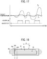
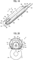
- curves indicated by reference signs Tx and Ty illustrate temperatures of the fixing belt 21 detected by the temperature sensor 28 at different positions. Specifically, the temperature Tx was detected at a position X in an end portion not corresponding to the openings 25e and 26e illustrated in FIG. 18 , and the temperature Ty was detected at a position Y corresponding to the openings 25e and 26e. As illustrated in FIG. 17 , the temperature Tx detected at the position X not corresponding to the openings 25e and 26e stably remained near the target control temperature.
- the temperature Ty detected at the position Y corresponding to the openings 25e and 26e fluctuated greatly from the target control temperature.
- the reason is considered as follows. Originally, the thin fixing belt 21 having a small thermal capacity easily changes its temperature. In addition, a portion of the fixing belt 21 corresponding to the openings 25e and 26e is directly irradiated with infrared light through the openings 25e and 26e. Therefore, it is considered that the temperature change increased with the ON / OFF timing of the halogen heater 23.
- the temperature sensor 28 used for controlling the temperature of the fixing belt 21 is preferably arranged to detect the temperature at the position that gives a relatively stable temperature and does not correspond to the openings 25e and 26e rather than the position corresponding to the openings 25e and 26e at which the temperature greatly fluctuates. Furthermore, it is preferable that the temperature sensor 28 detects the temperature at a portion of the fixing belt 21 which is not directly irradiated with infrared light. Therefore, preferably, the temperature sensor 28 detects the temperature at the portion of the fixing belt 21 inside the inner edges 250 of the openings 25e and the inner edges 260 of the openings 26e in the belt longitudinal direction E.
- the temperature sensor 28 may be disposed on the nip entrance side or the nip exit side. However, at the nip exit side, the temperature sensor 28 detects the temperature after the sheet absorbs the heat of the fixing belt 21. Therefore, preferably, the temperature sensor 28 is disposed at the nip entrance side in which the temperature sensor 28 can detect the temperature before the sheet absorbs the heat.
- the halogen heater 23 When the halogen heater 23 directly irradiates the fixing belt 21 with the infrared light through the openings 25e and 26e, preferably, the halogen heater 23 generates the heat while the fixing belt 21 rotates. Heat generation of the halogen heater 23 while the fixing belt 21 stops its rotation may cause a large temperature difference between a portion which is directly irradiated with the infrared light and a portion other than the portion and distortion in the fixing belt 21 due to thermal expansion. Therefore, the halogen heater 23 generates the heat during the rotation of the fixing belt 21, which can disperse areas heated by the direct irradiation of the infrared light in the belt rotation direction. As a result, the distortion due to the thermal expansion of the fixing belt 21 is reduced, and deformation and buckling breakage (kinking) of the fixing belt 21 are less likely to occur.
- wires 45 such as wire harnesses connected to both ends of the halogen heater 23 is preferably arranged so that the wires 45 pass through the openings 25f and 26f that open toward the belt longitudinal direction E and do not pass through the openings 25e and 26e that open upward in the stay 25 and the reflector 26 as illustrated in FIG. 19 in order to avoid deterioration and damage due to heat of the halogen heater 23.
- One end of each wire 45 is coupled to the halogen heater 23, and the other end of each wire 45 is coupled to an AC power supply.
- the wire 45 passing outside the side wall portion 25a of the stay 25 is disposed away from the stay 25, that is, at a non-contact position, specifically, for example, at a position indicated by reference sign 45A or 45B in FIG. 20 . Since the position inside the reflector 26 is affected by the heat from the halogen heater 23 and the reflector 26, preferably, the wire 45 is not arranged in such a position, that is, the position indicated by the reference sign 45C in FIG. 20 . When a resin cover 50 (or a guide) is disposed outside the stay 25 as in the example illustrated in FIG. 21 , arranging the wire 45 outside the cover 50 can reduce the influence of heat from the stay 25 to the wire 45.
- the wire 45 may be arranged on the step 50a. More preferably, to reduce the influence of the heat of the cover 50, the wire 45 may contact a plurality of ribs 50c disposed on the cover 50 to decrease a contact area between the wire 45 and the cover 50 rather than arranging the wire 45 in contact with the flat portion 50b near the step 50a.
- the bottom wall portion 25b of the stay 25 and a part of the reflector 26 corresponding to the bottom wall portion 25b have the openings 25e and 26e (see FIG. 8 ), but as illustrated in FIG. 22 , the side wall portion 25a of the stay 25 and a part of the reflector 26 corresponding to the side wall portion 25a may have the openings 25e and 26e having the same effect as described above.
- the side wall portion 25a and the bottom wall portion 25b of the stay 25 may be shortened in the belt longitudinal direction to expose at least a part of the sealing portion 40a outside the entire edge 251 of the stay 25 and the entire edge 261 of the reflector 26 in the belt longitudinal direction E.
- the above-described configuration further facilitates the heat dissipation from the sealing portion 40a and can effectively prevent the sealing portion 40a from overheating.
- one halogen heater 23 is disposed inside the loop of the fixing belt 21, but a plurality of heaters may be used. In a configuration using a plurality of heaters, it is preferable to arrange the openings 25e and 26e as described above, particularly for a heater having the innermost sealing portion 40a in the belt longitudinal direction E.
- the shapes of the stay 25 and the reflector 26 are not limited to the above-described embodiment and may be appropriately changed.
- the present disclosure may be applied to a fixing device not including the reflector 26.
- the fixing device according to the present disclosure is not limited to the fixing device 5 that conveys the sheet in the horizontal direction as illustrated in FIG. 1 .
- An installation direction of the fixing device 5 may be changed as appropriate, and the present disclosure is also applicable to the fixing device 5 that conveys the sheet in the vertical direction as illustrated in FIG. 24 .
- the present disclosure is not limited to the application of the fixing device including the halogen heater having the sealing portion.
- the present disclosure may be applied to a carbon heater having a sealing portion.
Landscapes
- Physics & Mathematics (AREA)
- General Physics & Mathematics (AREA)
- Fixing For Electrophotography (AREA)
Abstract
Description
- Embodiments of the present disclosure generally relate to a fixing device and an image forming apparatus incorporating the fixing device.
- An electrophotographic image forming apparatus such as a copier or a printer includes a fixing device to convey a recording medium such as a sheet on which an unfixed image is formed to a nip formed between members such as a roller and a belt facing each other, heat the recording medium, and fix the unfixed image on the recording medium.
- As such a fixing device, for example,
JP-6164014-B JP-2015-69094-A - In the fixing device including a support member such as the stay arranged around a heater that is the heat generator, the support member blocks heat radiation from the heater. Therefore, when the heater continues to generate heat, ambient temperature around the heater increases, and the high ambient temperature may cause an excessive rise in temperature of the heater.
- It is a general object of the present disclosure to provide an improved and useful fixing device in which the above-mentioned disadvantages are eliminated. In order to achieve the above-mentioned object, there is provided a fixing device according to
claim 1. Advantageous embodiments are defined by the dependent claims. - Advantageously, the fixing device includes a fixing member in a cylindrical shape, an opposite member disposed opposite an outer surface of the fixing member, a nip formation member disposed inside a loop of the fixing member, a support member disposed inside the loop of the fixing member and configured to support the nip formation member, and a heater disposed inside the loop of the fixing member. The nip formation member sandwiches the fixing member between the nip formation member and the opposite member and forms a nip between the nip formation member and the opposite member. The heater includes a tube having a sealing portion at least partially exposed out of the support member and a heat generator accommodated in the tube.
- According to the present disclosure, an excessive rise in temperature of the heater can be avoided.
- The aforementioned and other aspects, features, and advantages of the present disclosure would be better understood by reference to the following detailed description when considered in connection with the accompanying drawings, wherein:
-
FIG. 1 is a schematic cross-sectional view of an image forming apparatus according to an embodiment of the present disclosure; -
FIG. 2 is a vertical cross-sectional view of a fixing device viewed from a lateral side of the fixing device; -
FIG. 3 is a perspective view of the fixing device with the vertical cross-sectional view of the fixing device; -
FIG. 4 is a vertical cross-sectional view of the fixing device viewed from a front side of the fixing device; -
FIG. 5 is a perspective view of a belt holder; -
FIG. 6 is a perspective view of the belt holder according to a variation; -
FIG. 7 is a schematic configuration diagram of a halogen heater; -
FIG. 8 is a perspective view of a stay and a reflector; -
FIG. 9 is a cross-sectional front view illustrating a main configuration in an end portion of the fixing device according to a first embodiment; -
FIG. 10 is a cross-sectional front view illustrating a main configuration in an end portion of the fixing device according to a second embodiment of the present disclosure; -
FIG. 11 is a cross-sectional front view illustrating a main configuration in an end portion of the fixing device according to a third embodiment of the present disclosure; -
FIG. 12 is a graph illustrating a heat generation distribution of a filament that generates heat larger in a center portion than in end portions in the longitudinal direction; -
FIG. 13 is a graph illustrating a heat generation distribution of a filament that generates heat larger in the end portions than in the center portion in the longitudinal direction; -
FIG. 14 is a cross-sectional front view illustrating a main configuration in an end portion of the fixing device according to a fourth embodiment of the present disclosure; -
FIG. 15 is a cross-sectional front view illustrating a main configuration in an end portion of the fixing device according to a fifth embodiment of the present disclosure; -
FIG. 16 is a graph illustrating a comparison between the embodiment of the present disclosure and a comparative example about a temperature rise of the fixing belt outside a sheet conveyance span; -
FIG. 17 is a graph illustrating changes in temperatures of the fixing belt detected by temperature sensors at a position corresponding to an opening and a position not corresponding to the opening; -
FIG. 18 is a diagram illustrating positions at which the temperature sensors detect the temperatures of the fixing belt; -
FIG. 19 is a diagram illustrating how to arrange wires; -
FIG. 20 is a diagram illustrating a specific example of how to arrange wires; -
FIG. 21 is a diagram illustrating another specific example of how to arrange wires; -
FIG. 22 is a perspective view illustrating a variation of the stay and the reflector; -
FIG. 23 is a perspective view illustrating another variation of the stay and the reflector; -
FIG. 24 is a schematic diagram illustrating an example of a configuration of the image forming apparatus including a fixing device which conveys a sheet in a vertical direction; -
FIG. 25 is a perspective view of a stay and a reflector according to a comparative example; and -
FIG. 26 is a cross-sectional front view illustrating a main configuration in an end portion of the fixing device according to the comparative example. - The accompanying drawings are intended to depict embodiments of the present disclosure and should not be interpreted to limit the scope thereof. The accompanying drawings are not to be considered as drawn to scale unless explicitly noted.
- In describing embodiments illustrated in the drawings, specific terminology is employed for the sake of clarity. However, the disclosure of this specification is not intended to be limited to the specific terminology so selected and it is to be understood that each specific element includes all technical equivalents that have a similar function, operate in a similar manner, and achieve a similar result.
- Although the embodiments are described with technical limitations with reference to the attached drawings, such description is not intended to limit the scope of the disclosure and all of the components or elements described in the embodiments of this disclosure are not necessarily indispensable.
- With reference to drawings, a description is given below of the present disclosure. In the drawings to describe following embodiments of the present disclosure, identical reference numerals are assigned to elements such as members and parts that have an identical function or an identical shape as long as differentiation is possible and a description of those elements is omitted once the description is provided.
-
FIG. 1 is a schematic diagram illustrating a configuration of an image forming apparatus according to an embodiment of the present disclosure. Referring toFIG. 1 , a configuration and operation of the image forming apparatus according to the present embodiment are described below. - An
image forming apparatus 1 illustrated inFIG. 1 is a monochrome electrophotographic laser printer. Theimage forming apparatus 1 according to the embodiments of the present disclosure may be a printer, a copier, a facsimile machine, a multifunction peripheral (MFP) having at least two of copying, printing, scanning, facsimile, and plotter functions. Theimage forming apparatus 1 is not limited to a monochrome image forming apparatus and may be a color image forming apparatus. - As illustrated in
FIG. 1 , theimage forming apparatus 1 includes animage forming device 2 to form an image, a recordingmedium feeding device 3 to feed a sheet P as a recording medium, a transfer device 4 to transfer the image onto the fed sheet P, afixing device 5 to fix the image transferred onto the sheet P, and asheet ejection device 6 to eject the sheet P with the fixed image to an outside of theimage forming apparatus 1. - The
image forming device 2 includes a drum-shaped photoconductor 7, acharging roller 8 as a charging device to charge a surface of thephotoconductor 7, anexposure device 9 as a latent image forming device that exposes the surface of thephotoconductor 7 to form an electrostatic latent image on thephotoconductor 7, a developingroller 10 as a developing device that supplies toner as a developer to the surface of thephotoconductor 7 to visualize the electrostatic latent image, and acleaning blade 11 as a cleaner to clean the surface of thephotoconductor 7. - As an image forming operation start is instructed, in the
image forming device 2, thephotoconductor 7 starts to rotate, and thecharging roller 8 uniformly charges the surface of thephotoconductor 7 to a high potential. Next, based on image data of an original document read by a scanner or print data instructed by a terminal device, theexposure device 9 exposes the surface of thephotoconductor 7. Potential of an exposed surface drops, and the electrostatic latent image is formed on thephotoconductor 7. The developingroller 10 supplies toner to the electrostatic latent image, thereby developing the latent image into the toner image on thephotoconductor 7. - The toner image formed on the
photoconductor 7 is transferred onto the sheet P in a transfer nip between thephotoconductor 7 and atransfer roller 15 disposed in the transfer device 4. The sheet P is fed from the recordingmedium feeding device 3. In the recordingmedium feeding device 3, asheet feeding roller 13 feeds the sheet P from asheet tray 12 to a feeding path one by one. Atiming roller pair 14 sends out the sheet P fed from thesheet tray 12 to a transfer nip, timed to coincide with the toner image on thephotoconductor 7. The toner image on thephotoconductor 7 is transferred onto the sheet P at the transfer nip. After the toner image is transferred from thephotoconductors 7 onto the sheet P, thecleaning blade 11 removes residual toner on thephotoconductor 7. - The sheet P bearing the toner image is conveyed to the
fixing device 5. In thefixing device 5, heat and pressure when the sheet P passes through between a fixingbelt 21 and apressure roller 22 fixes the toner image onto the sheet P. Subsequently, the sheet P is conveyed to thesheet ejection device 6, and anejection roller pair 16 ejects the sheet P outside theimage forming apparatus 1, and a series of print operations are completed. - With reference to
FIGS. 2 to 6 , a detailed description is provided of a construction of the fixingdevice 5 according to embodiments of the present disclosure. -
FIG. 2 is a vertical cross-sectional view of the fixingdevice 5 viewed from a lateral side of the fixingdevice 5,FIG. 3 is a perspective view of the fixingdevice 5 with the vertical cross-sectional view of the fixingdevice 5, andFIG. 4 is a vertical cross-sectional view of the fixingdevice 5 viewed from a front side of the fixingdevice 5. In addition,FIG. 5 is a perspective view of abelt holder 30 to support the fixingbelt 21, andFIG. 6 is a perspective view of a variation of thebelt holder 30. - As illustrated in
FIG. 2 , the fixingdevice 5 includes the fixingbelt 21, thepressure roller 22, ahalogen heater 23, anip formation member 24, astay 25, areflector 26, guides 27, andtemperature sensors 28. - The fixing
belt 21 is a cylindrical fixing member to fix an unfixed image T to the sheet P and is disposed on the side of the sheet P on which the unfixed image is held. The fixingbelt 21 in the present embodiment is an endless belt or film, including a base layer formed on an inner side of the fixingbelt 21 and made of a metal such as nickel and stainless steel (SUS) or a resin such as polyimide, and a release layer formed on the outer side of the fixingbelt 21 and made of tetrafluoroethylene-perfluoroalkylvinylether copolymer (PFA), polytetrafluoroethylene (PTFE), or the like. Optionally, an elastic layer made of rubber such as silicone rubber, silicone rubber foam, and fluoro rubber may be interposed between the base layer and the release layer. While the fixingbelt 21 and thepressure roller 22 press the unfixed toner image against the sheet P to fix the toner image onto the sheet P, the elastic layer having a thickness of about 100 micrometers elastically deforms to absorb slight surface asperities of the fixingbelt 21, preventing variation in gloss of the toner image on the sheet P. Additionally, in the present embodiment, the fixingbelt 21 is thin and has a small loop diameter to decrease the thermal capacity of the fixingbelt 21. For example, the base layer of the fixingbelt 21 has a thickness of from 20 µm to 50 µm and the release layer has a thickness of from 10 µm to 50 µm. Thus, the fixingbelt 21 has a total thickness not greater than 1 mm. In addition, when the fixingbelt 21 includes the elastic layer, the thickness of the elastic layer may be set to 100 to 300 µm. In order to further decrease the thermal capacity of the fixingbelt 21, the fixingbelt 21 may have the total thickness not greater than 0.20 mm and preferably not greater than 0.16 mm. In the present embodiment, the fixingbelt 21 may have a loop diameter from 20 to 40 mm. Preferably, the loop diameter of the fixingbelt 21 may not be greater than 30 mm. - The
pressure roller 22 is an opposite member disposed opposite an outer surface of the fixingbelt 21. Thepressure roller 22 includes a cored bar; an elastic layer coating the cored bar and being made of silicone rubber foam, fluoro rubber, or the like; and a release layer coating the elastic layer and being made of PFA, PTFE, or the like. According to the present embodiment, thepressure roller 22 is a solid roller. Alternatively, thepressure roller 22 may be a hollow roller. When thepressure roller 22 is the hollow roller, a heater such as a halogen heater may be disposed inside thepressure roller 22. The elastic layer of thepressure roller 22 may be made of solid rubber. Alternatively, if no heater is disposed inside thepressure roller 22, the elastic layer of thepressure roller 22 is preferably made of sponge rubber to enhance thermal insulation of thepressure roller 22. Such a configuration reduces heat conduction from the fixingbelt 21 to thepressure roller 22 and improves heating efficiency of the fixingbelt 21. - A driver inside the
image forming apparatus 1 drives and rotates thepressure roller 22 in a direction indicated by an arrow A inFIG. 2 . The rotation of thepressure roller 22 drives the fixingbelt 21 to rotate in a direction B inFIG. 2 due to frictional force therebetween. After the toner image is transferred onto the sheet P, the sheet P bearing the unfixed toner image is conveyed to a nip N between the fixingbelt 21 and thepressure roller 22. Therotating fixing belt 21 and therotating pressure roller 22 conveys the sheet P, and the sheet P passes through the nip N. When the sheet P passes through the nip N, heat and pressure applied to the sheet P fixes the unfixed image T to the sheet P. - The
pressure roller 22 and the fixingbelt 21 are able to contact and separate each other. If the sheet is jammed in the nip N, separating thepressure roller 22 and the fixingbelt 21 from each other and opening the nip N enables the jammed sheet to be removed. One of thepressure roller 22 and the fixingbelt 21 may be fixed and the other may be movable so that thepressure roller 22 and the fixingbelt 21 contact and separate each other. Alternatively, both thepressure roller 22 and the fixingbelt 21 may be moved so that thepressure roller 22 and the fixingbelt 21 contact and separate each other. - The
halogen heater 23 is a heating member disposed inside a loop of the fixingbelt 21 and emitting infrared light, and radiant heat from thehalogen heater 23 heats the fixingbelt 21 via thenip formation member 24. Alternatively, instead of thehalogen heater 23, a carbon heater, a ceramic heater or the like may be employed as the heater. - The
nip formation member 24 and thepressure roller 22 sandwich the fixingbelt 21 to form the nip N. Specifically, thenip formation member 24 extends inside the loop of the fixingbelt 21 in a longitudinal direction that is also a direction of a rotation axis of the fixing belt 21 (hereinafter called a belt longitudinal direction) and has a planar nipformation portion 24a that is in contact with an inner circumferential surface of the fixingbelt 21, and a pair ofbent portions 24b that are bent from both end portions of thenip formation portion 24a in a belt rotation direction B to the opposite side to thepressure roller 22. A pressing member such as a spring presses thepressure roller 22 against thenip formation member 24, which causes thepressure roller 22 to contact the fixingbelt 21 and forms the nip N therebetween. - A
nip formation surface 24c of thenip formation portion 24a on the fixingbelt 21 side may be coated with an alumite treatment or a fluororesin material in order to improve abrasion resistance and slidability when the fixingbelt 21 rotates. Furthermore, a lubricant such as a fluorine-based grease may be applied to thenip formation surface 24c in order to ensure the slidability over time. In the present embodiment, thenip formation member 24 has a planar surface. Alternatively, thenip formation member 24 may have another shape. For example, thenip formation member 24 having a concave shape recessed to the side opposite to thepressure roller 22 leads the outlet of the sheet in the fixing nip N to be closer to thepressure roller 22, which improves separation of the sheet from the fixingbelt 21. - The
nip formation member 24 is made of a material having a thermal conductivity larger than that of thestay 25. For example, the material of thenip formation member 24 is preferably copper (thermal conductivity: 398 W / mK) or aluminum (thermal conductivity: 236 W / mK). Thenip formation member 24 made of the material having such a large thermal conductivity absorbs the radiant heat from thehalogen heater 23 and effectively transmits heat to the fixingbelt 21. For example, setting the thickness of thenip formation member 24 to 1 mm or less can shorten a heat transfer time in which the heat transfers from thenip formation member 24 to the fixingbelt 21, which is advantageous in shortening a warm-up time of the fixingdevice 5. In contrast, setting the thickness of thenip formation member 24 to be larger than 1 mm and 5 mm or less can improve a heat storage capacity of thenip formation member 24. - The
stay 25 is a support member to support thenip formation member 24 against the pressing force from thepressure roller 22. In the present embodiment, thestay 25 includes a pair ofside wall portions 25a extending in a pressing direction of the pressure roller 22 (the vertical direction inFIG. 2 ) and arranged in parallel with each other and abottom wall portion 25b intersecting theside wall portions 25a and connecting ends of theside wall portions 25a on the opposite sides with respect to thepressure roller 22. Theside wall portions 25a ofstay 25 are in contact with both ends of thenip formation member 24 in the belt rotation direction B via thereflector 26, and, as a result, thestay 25 supports thenip formation member 24. Theside wall portions 25a extending in the pressing direction of thepressure roller 22 strengthen the rigidity of thenip formation member 24 in the pressing direction and reduces the bend of thenip formation member 24 caused by the pressing force of thepressure roller 22. Such a configuration can form the nip N having a uniform width in the longitudinal direction and applying a uniform pressure to the sheet P in the longitudinal direction. Thestay 25 is preferably made of an iron-based metal such as stainless steel (SUS) or steel electrolytic cold commercial (SECC) that is electrogalvanized sheet steel to ensure rigidity. - The
reflector 26 are disposed opposite thehalogen heater 23 inside the loop of the fixingbelt 21 to reflect radiant heat that is infrared light emitted from thehalogen heater 23 to the nipformation member 24. In the present embodiment, thereflector 26 includes areflector portion 26a formed as an ellipse cross-section and a pair ofbent portions 26b bent from both ends of thereflector portion 26a in a direction in which the bent portions separate from each other in the belt rotation direction B. Eachbent portion 26b is sandwiched between eachside wall portion 25a of thestay 25 and thenip formation portion 24a of thenip formation member 24 to hold thereflector 26. - The infrared light reflected by the
reflector 26 is emitted to the nipformation member 24 and heats thenip formation member 24. As described above, thehalogen heater 23 directly irradiates thenip formation member 24 with the infrared light, and, additionally, thenip formation member 24 is also irradiated with the infrared light reflected by thereflector 26. Therefore, thenip formation member 24 is effectively heated. Since thereflector 26 is interposed between thehalogen heater 23 and thestay 25, thereflector 26 has a function of blocking the infrared light from thehalogen heater 23 to thestay 25. This function reduces wasteful energy use to heat thestay 25. Additionally, in the present embodiment, thermal insulation of the layer of air in a gap between thestay 25 and thereflector 26 blocks heat transfer to thestay 25. - The surface of the
reflector 26 facing thehalogen heater 23 is treated with mirror finish or the like to increase reflectance. In the present embodiment, reflectance is measured using the spectrophotometer that is the ultraviolet visible infrared spectrophotometer UH4150 manufactured by Hitachi High-Technologies Corporation in which the incident angle is set 5°. In general, the color temperature of the halogen heater varies depending on the application. The color temperature of the heater for the fixing device is about 2500 K. The reflectance of thereflector 26 is preferably 70% or more with wavelengths of high emission intensity in thehalogen heater 23, that is, specifically the wavelengths of 900 to 1600 nm and more preferably 70% or more with the wavelengths of 1000 to 1300 nm. - Alternatively, the
stay 25 may have the function of reflection and thermal insulation of thereflector 26. For example, performing the thermal insulation treatment or the mirror finishing on the inner surface of thestay 25 in thehalogen heater 23 side enables thestay 25 to function as thereflector 26. Such a configuration can obviate thereflector 26 that is a separate component from thestay 25. The reflectance of thestay 25 subjected to the mirror finishing is preferably similar to the reflectance of thereflector 26. - The
guides 27 contacts the inner peripheral surface of the fixingbelt 21 to guide therotating fixing belt 21. In the present embodiment, theguides 27 are disposed on both the upstream side and the downstream side of the nip N in the belt rotational direction B. Theguide 27 includes anattachment portion 27a fixed to thestay 25 and acurved guide portion 27b in contact with the inner peripheral surface of the fixingbelt 21. As illustrated inFIG. 3 , theguide portion 27b includes a plurality ofribs 27c that are projections provided at equal distances in the belt longitudinal direction on a guide surface of theguide portion 27b that is the surface of theguide portion 27b in the fixingbelt 21 side. Guiding the fixingbelt 21 along the guide surface having the plurality ofribs 27c enables smooth rotation of the fixingbelt 21 without large deformation of the fixingbelt 21. - The
temperature sensors 28 face the outer surface of the fixingbelt 21 to detect temperatures of the fixingbelt 21. In the present embodiment, thetemperature sensors 28 are disposed at two positions, the central position of the fixingbelt 21 in the belt longitudinal direction, and one end position of the fixingbelt 21 in the belt longitudinal direction. Thetemperature sensor 28 detects the temperature of the outer circumferential surface of the fixingbelt 21, and output of thehalogen heater 23 is controlled based on the detected temperatures so that the temperature of the fixingbelt 21 becomes a desired temperature that is a fixing temperature. Thetemperature sensor 28 may be either contact type or non-contact type. Thetemperature sensor 28 may be a known temperature sensor type such as a thermopile, a thermostat, a thermistor, or a non-contact (NC) sensor. - As illustrated in
FIG. 4 , eachcylindrical belt holder 30 as a fixing member support to support a lateral end of the fixingbelt 21 is inserted in each of both lateral ends of the fixingbelt 21. As described above, thebelt holders 30 inserted into the both lateral ends of the fixingbelt 21 support the fixingbelt 21 in a state in which the fixingbelt 21 is not basically applied with tension in a circumferential direction thereof while the fixingbelt 21 does not rotate, that is, by a free belt system. - As illustrated in
FIGS. 3 to 5 , thebelt holder 30 includes a C-shapedsupporter 30a inserted into the inner periphery of the fixingbelt 21 to support the fixingbelt 21 and aflange 30b that contacts an end surface of the fixingbelt 21 to stop a movement of the fixingbelt 21 in the longitudinal direction of the fixingbelt 21, that is, walking of the fixingbelt 21 in the longitudinal direction. As illustrated inFIG. 6 , thesupporter 30a may have a cylindrical shape which is continuous over its entire circumference. As illustrated inFIG. 4 , thebelt holders 30 are fixed on a pair ofside plates 31 that are frames of the fixingdevice 5. Thebelt holder 30 has anopening 30c as illustrated inFIG. 5 , and both ends of thehalogen heater 23 and thestays 25 are supported by theside plates 31 through theopenings 30c. Thehalogen heater 23 and thestays 25 may be supported by thebelt holders 30. - Subsequently, with reference to
FIG. 7 , a description is provided of a configuration of the halogen heater according to the embodiment of the present disclosure. - As illustrated in
FIG. 7 , thehalogen heater 23 includes abulb 40 which is a cylindrical tube made of quartz glass or the like, afilament 41 as a heating generator accommodated in thebulb 40, a thin metal foils 42 made of molybdenum or the like, inner leads 43 and outer leads 44. - The
filament 41 includes coils made of a metal wire such as a tungsten wire and is accommodated in thebulb 40 along the longitudinal direction of thebulb 40. Thebulb 40 is filled with an inert gas such as a halogen gas. At both ends in the longitudinal direction of thebulb 40, sealingportions 40a are formed that are flattened to prevent the internal gas from leaking out. Each sealingportion 40a accommodates themetal foil 42. The metal foils 42 are connected to both ends of thefilament 41 via the inner leads 43. Additionally, theouter lead 44 is connected to themetal foil 42 at the side opposite to the side where theinner lead 43 is connected. A part of theouter lead 44 is out of the sealingportion 40a, and an end of the part is connected to a power supply via a terminal such as a metal cap or a harness. Since thefilament 41 is connected to the power supply via theouter lead 44, themetal foil 42, and theinner lead 43, power supplied from the power supply causes thefilament 41 to emit infrared light and generate heat. The metal foils 42, the inner leads 43, and the outer leads 44 hardly generate heat when the power is supplied from the power supply. - The
bulb 40 used for thehalogen heater 23 is generally made of a heat-resistant material, but high temperature may cause a crack such as a micro crack in the sealingportion 40a because of its structure. That is, thefilament 41 generates heat, and the sealingportion 40a becomes high temperature. The high temperature oxidizes themetal foil 42 and causes a volumetric expansion of themetal foil 42. The volumetric expansion of themetal foil 42 generates a force to expand the sealingportion 40a from the inside. When the sealingportion 40a cannot withstand the force, the force causes the crack in the sealingportion 40a. For example, when the temperature of the sealingportion 40a exceeds 350°C, the crack may occur in the sealingportion 40a. The temperature when the crack occurs is different depending on the configuration and specifications of thehalogen heater 23. - When members such as the
stay 25 and thereflector 26 are arranged around the sealingportion 40a, the members prevent heat radiation from the sealingportion 40a and change the space around the sealingportion 40a to a high-temperature environment. In particular, for example, as illustrated inFIG. 26 , when thehalogen heater 23 is arranged inside thestay 25 and thereflector 26 that are continuously formed in a substantially U-shaped cross section in the longitudinal direction as illustrated inFIG. 25 , the sealingportion 40a is surrounded by thestay 25 and thereflector 26 on three sides, the upper side inFIG. 26 and two sides in a direction perpendicular to the paper surface ofFIG. 26 . Since thestay 25 and thereflector 26 block the hot air around the sealingportion 40a and prevent the hot air from flowing outside, the space around the sealingportion 40a becomes the high-temperature environment. - To prevent the end of the
halogen heater 23 in the longitudinal direction, especially the sealingportion 40a, from overheating, the embodiments of the present disclosure employ the following configurations. -
FIG. 8 is a perspective view illustrating thestay 25 and thereflector 26 according to a first embodiment of the present disclosure. - As illustrated in
FIG. 8 , in the embodiment of the present disclosure, thestay 25 hasopenings 25e that open upward inFIG. 8 and are provided at both end regions of thestay 25 in the longitudinal direction that is the belt longitudinal direction E. Like thestay 25, thereflector 26 also hasopenings 26e that open upward inFIG. 8 at both end regions in the longitudinal direction that is the belt longitudinal direction E. - As illustrated in
FIG. 9 , when thestay 25 and thereflector 26 according to the present embodiment are arranged inside the loop of the fixingbelt 21, theopening 25e of thestay 25 and theopening 26e of thereflector 26 are disposed at an end region in a belt width direction and are open on the side opposite to the nipformation member 24 with respect to thehalogen heater 23. The above-described arrangement of theopenings portion 40a and the vicinity of the sealingportions 40a, which are opposite to the nipformation member 24. AlthoughFIG. 9 illustrates the configuration of one end of the fixing device, the other end of the fixing device has the same configuration. - As described above, in the embodiment of the present disclosure, the
openings stay 25 and thereflector 26 in the longitudinal direction open one side of the space around the sealingportions 40a, that is, the side opposite to the nipformation member 24 with respect to thehalogen heater 23. Specifically, at least a part of the sealingportion 40a (a part at anouter edge 401 side in the belt longitudinal direction) is disposed outside anedge 250 of thebottom wall portion 25b, which is one of edges of thebottom wall portion 25b and a pair ofside wall portions 25a that constitute thestay 25 in the longitudinal direction of each of thebottom wall portion 25b and theside wall portions 25a, in the belt longitudinal direction E (that is, left side inFIG. 9 ). In the above-described configuration, a portion of thebottom wall portion 25b of thestay 25 facing at least the part of the sealingportion 40a is removed to open a portion of the space around the sealingportion 40a. In thereflector 26, a part of end portion in the longitudinal direction is cut and removed from thereflector portion 26a having the U-shaped cross section to form anedge 260 in the longitudinal direction of thereflector 26. In the belt longitudinal direction E, at least a part of the sealingportion 40a is disposed outside theedge 260 of thereflector 26. The above-described configuration easily releases the air around the sealingportion 40a to the outside through theopenings portion 40a is exposed out of thestay 25 and thereflector 26, thestay 25 and thereflector 26 are unlikely to block heat from the space around the sealingportion 40a of thehalogen heater 23. That is, compared with the comparative example illustrated inFIGS. 25 and 26 , the heat in the space around the sealingportion 40a is easily released, which can prevent the overheating of the sealingportion 40a. - Specifically, when the fixing device in the comparative example illustrated in
FIGS. 25 and 26 performed the fixing process and continuously passed 500 sheets, the temperature at the sealingportion 40a exceeded 350°C, a temperature that may cause the crack in the sealingportion 40a. When the fixing device in the comparative example performed the fixing process and continuously passed 1000 sheets, the temperature at the sealingportion 40a reached 380°C. On the other hand, when the fixing device according to the embodiment of the present disclosure similarly performed the fixing process and continuously passed 500 sheets or 1000 sheets, the temperature at the sealingportion 40a was maintained at about 320°C and did not reach 350°C as the temperature that may cause the crack in the sealingportion 40a. - As described above, since the configuration according to the embodiment of the present disclosure can prevent the sealing
portion 40a from overheating, the configuration can prevent the occurrence of cracks and disconnections due to an excessive temperature rise at the sealingportion 40a and improve the reliability of thehalogen heater 23. In particular, the configuration according to the embodiment of the present disclosure is suitable for the fixing device mounted on a small image forming apparatus used in an office or the like. Generally, since most of the small image forming apparatuses used in the office or the like are designed on the assumption that the number of output sheets per one print job is small, the most of the small image forming apparatuses do not include a blower fan or the like to avoid the temperature rise when the small image forming apparatuses print a large number of sheets. Therefore, applying the configuration according to the embodiment of the present disclosure to such a fixing device can prevent thehalogen heater 23 from overheating without providing a blower fan or the like and provide a small and highly reliable fixing device. - In the comparative example not having the
openings portion 40a from overheating, the sealingportion 40a should be arranged at a position at which the heat is easily released, that is, the position outside an outer edge 301 (seeFIG. 26 ) of thebelt holder 30 in the belt longitudinal direction E. Without such countermeasure, the embodiment of the present disclosure can prevent the sealingportion 40a from overheating. That is, according to the embodiment of the present disclosure, without arranging the sealingportion 40a outside the outer edge 301 (seeFIG. 9 ) of thebelt holder 30 in the belt longitudinal direction E, the heat around the sealingportion 40a can be easily dissipated through theopenings FIG. 9 , the sealingportion 40a can be arranged inside theouter edge 301 of thebelt holder 30 in the belt longitudinal direction E, which can reduce the size of the fixing device. To reduce the size of the fixing device as described above, at least theouter edge 401 of the sealingportion 40a in the belt longitudinal direction E is disposed on the inner side of theouter edge 301 of thebelt holder 30 in the belt longitudinal direction E. InFIG. 9 , a part of the sealingportion 40a is disposed on the inner side of theinner edge 302 of thebelt holder 30 in the belt longitudinal direction E. However, depending on the configuration and specifications of the fixing device, theentire sealing portion 40a may be disposed on the inner side of theinner edge 302 of thebelt holder 30 to further reduce the size of the fixing device. - As illustrated in
FIG. 9 , theopenings belt holder 30 in the belt longitudinal direction E so that at least a part of theopenings belt holder 30 in the belt longitudinal direction E. That is, theinner edge 250 of theopening 25e and theinner edge 260 of theopening 26e in the belt longitudinal direction E are preferably arranged inside theinner edge 302 of thebelt holder 30 in the belt longitudinal direction E. The above arrangement in which at least a part of theopenings belt holder 30 in the belt longitudinal direction E can prevent thebelt holder 30 from blocking heat dissipation through theopenings openings - In short, in order to facilitate the heat dissipation from the
openings portion 40a from overheating, theopenings portion 40a and does not overlap thebelt holder 30, that is, the region indicated by a reference sign C inFIG. 9 . Additionally, thereflector 26 preferably has anopening 26e at a position corresponding to theopening 25e of thestay 25 so as not to hinder heat dissipation from theopening 25e of thestay 25. In the embodiment illustrated inFIGS. 8 and9 , since theopening 26e of thereflector 26 is formed so as not to overlap with theentire opening 25e of thestay 25, the configuration in the embodiment can effectively prevent the sealingportion 40a from overheating. - From the viewpoint of thermal efficiency, the heat dissipated through the
openings belt 21 as much as possible. Therefore, as illustrated inFIG. 9 , theinner edge 250 of theopening 25e and theinner edge 260 of theopening 26e in the belt longitudinal direction E are preferably arranged within the range of the fixingbelt 21 in the belt longitudinal direction E. Arranging theopenings openings belt 21 and can reduce wasteful energy consumption caused by heat transfer to members other than the fixingbelt 21. -
FIG. 10 is a cross-sectional front view illustrating an end portion of the fixing device according to a second embodiment in which theopenings FIGS. 9 and 10 ) in the belt longitudinal direction E as compared with the first embodiment illustrated inFIG. 9 . - In the second embodiment illustrated in
FIG. 10 , theinner edge 250 of theopening 25e and theinner edge 260 of theopening 26e in the belt longitudinal direction E are arranged corresponding to theinner edge 402 of the sealingportion 40a in the belt longitudinal direction E. The above-described arrangement in which theopenings entire sealing portion 40a more easily releases hot air around the sealingportion 40a through theopenings portion 40a from overheating. -
FIG. 11 is a cross-sectional front view illustrating the end portion of the fixing device according to a third embodiment in which theopenings FIG. 10 . - In the third embodiment illustrated in
FIG. 11 , theinner edge 250 of theopening 25e and theinner edge 260 of theopening 26e in the belt longitudinal direction E are arranged corresponding to anedge 410, which is an outer edge if thefilament 41 has the outer edge and an inner edge, of thefilament 41 in the belt longitudinal direction E. Since the infrared light radiated from thefilament 41 also spreads outward in the belt longitudinal direction E, the infrared light radiated from theedge 410 of thefilament 41 passes through theopenings belt 21. Directly irradiating the inner peripheral surface of the fixingbelt 21 with the infrared light through theopenings belt 21 in the longitudinal direction E. The above-described configuration can reduce the heating time (first print time) from a heating standby state to a state where fixing operation is executable and solve the shortage of heat during high-speed rotation. - By the way, there is the halogen heater including a filament that ununiformly generates heat in the longitudinal direction. For example, such a halogen heater generates heat set to be different between a center portion and end portions in the longitudinal direction.
FIG. 12 is a graph illustrating an example of a heat generation distribution in a type of the filament that generates heat larger in the end portions than in the center portion in the longitudinal direction.FIG. 13 is a graph illustrating an example of a heat generation distribution in a type of the filament that generates heat larger in the center portion than in the end portions in the longitudinal direction. InFIGS. 12 and13 , a range indicated by a reference sign D means a large heat generation region in which the filament generates larger heat than another region in the filament, and a range indicated by a reference sign W means a maximum sheet conveyance span when a sheet having a maximum width among sheets used in the image forming apparatus passes through the fixing nip. - A continuous fixing process when the
image forming apparatus 1 continuously prints many images may accumulate heat in a region of the fixingbelt 21 outside a sheet conveyance span in which heat is not easily taken away by the sheet, which may excessively raise the temperature in the region of the fixingbelt 21 outside the sheet conveyance span. In such a case, using the halogen heater including the filament that generates a small amount of heat in the end portions as illustrated inFIG. 12 can reduce heat accumulation in the region of the fixingbelt 21 outside the sheet conveyance span and prevent the temperature at the region from excessively rising. On the other hand, using the halogen heater including the filament having the hat generation distribution as illustrated inFIG. 13 can prevent a temperature drop in the region of the fixingbelt 21 outside the sheet conveyance span when an amount of heat in the region of the fixingbelt 21 outside the sheet conveyance span tends to be insufficient. - When the fixing device uses the halogen heater having the ununiform heat generation distribution in the longitudinal direction as described above, ranges of the
openings FIG. 13 , the ranges of theopenings FIG. 14 to a position corresponding to the large heat generation region D in the end portions of thefilament 41. That is, theinner edge 250 of theopening 25e and theinner edge 260 of theopenings 26e in the belt longitudinal direction E are arranged inside the outer edge d1 of the large heat generation region D in the belt longitudinal direction E. The above-described arrangement can broaden a range on the fixingbelt 21 which is directly irradiated with the infrared light in the end portions of the fixingbelt 21 in the belt longitudinal direction E and effectively prevent the temperature drop at the end portion of the fixingbelt 21 in the belt longitudinal direction E. Theopenings filament 41 can reduce the influence of heat on the sealingportion 40a because the hot air around the sealingportion 40a is easily released through theopenings filament 41 is large. InFIG. 14 , theopenings filament 41, that is, theinner edge 250 of theopening 25e and theinner edge 260 of theopening 26e in the belt longitudinal direction E are arranged at the same position of the inner edge d2 of the large heat generation region D or inside the inner edge d2 in the belt longitudinal direction E. However, theopenings filament 41. - As in a fifth embodiment illustrated in
FIG. 15 , the ranges of theopenings FIG. 15 , theinner edge 250 of theopening 25e and theinner edge 260 of theopening 26e in the belt longitudinal direction E correspond to the edge of the maximum sheet conveyance span W through which the maximum sheet passes in the nip N. Theopenings halogen heater 23 and a part of the fixingbelt 21 which are outside the sheet conveyance span from excessively rising temperature. -
FIG. 16 is a graph illustrating a comparison between the fifth embodiment of the present disclosure and the comparative example about the temperature rise of the fixing belt outside the sheet conveyance span. The temperature of the fixing belt outside the sheet conveyance span in the fifth embodiment of the present disclosure illustrated inFIG. 15 is indicated by a reference sign H inFIG. 16 . As illustrated inFIG. 16 , the configuration according to the fifth embodiment of the present disclosure can prevent the temperature of the fixing belt outside the sheet conveyance span from excessively rising and maintain the temperature of the fixing belt outside the sheet conveyance span near the target temperature. The temperature of the fixing belt outside the sheet conveyance span in the comparative example not having theopenings FIG. 16 . As illustrated inFIG. 16 , the temperature of the fixing belt outside the sheet conveyance span exceeds the target temperature after the start of continuous printing and tends to gradually rise. The ranges of theopenings portion 40a from excessively rising, and prevent the sealingportion 40a from occurring cracks and breaks. - Preferably, the position of the
temperature sensor 28 is determined based on positions of theopenings FIG. 17 , curves indicated by reference signs Tx and Ty illustrate temperatures of the fixingbelt 21 detected by thetemperature sensor 28 at different positions. Specifically, the temperature Tx was detected at a position X in an end portion not corresponding to theopenings FIG. 18 , and the temperature Ty was detected at a position Y corresponding to theopenings FIG. 17 , the temperature Tx detected at the position X not corresponding to theopenings openings thin fixing belt 21 having a small thermal capacity easily changes its temperature. In addition, a portion of the fixingbelt 21 corresponding to theopenings openings halogen heater 23. According to this result, to avoid misdetection, thetemperature sensor 28 used for controlling the temperature of the fixingbelt 21 is preferably arranged to detect the temperature at the position that gives a relatively stable temperature and does not correspond to theopenings openings temperature sensor 28 detects the temperature at a portion of the fixingbelt 21 which is not directly irradiated with infrared light. Therefore, preferably, thetemperature sensor 28 detects the temperature at the portion of the fixingbelt 21 inside theinner edges 250 of theopenings 25e and theinner edges 260 of theopenings 26e in the belt longitudinal direction E. Thetemperature sensor 28 may be disposed on the nip entrance side or the nip exit side. However, at the nip exit side, thetemperature sensor 28 detects the temperature after the sheet absorbs the heat of the fixingbelt 21. Therefore, preferably, thetemperature sensor 28 is disposed at the nip entrance side in which thetemperature sensor 28 can detect the temperature before the sheet absorbs the heat. - When the
halogen heater 23 directly irradiates the fixingbelt 21 with the infrared light through theopenings halogen heater 23 generates the heat while the fixingbelt 21 rotates. Heat generation of thehalogen heater 23 while the fixingbelt 21 stops its rotation may cause a large temperature difference between a portion which is directly irradiated with the infrared light and a portion other than the portion and distortion in the fixingbelt 21 due to thermal expansion. Therefore, thehalogen heater 23 generates the heat during the rotation of the fixingbelt 21, which can disperse areas heated by the direct irradiation of the infrared light in the belt rotation direction. As a result, the distortion due to the thermal expansion of the fixingbelt 21 is reduced, and deformation and buckling breakage (kinking) of the fixingbelt 21 are less likely to occur. - Further, as in an example illustrated in
FIG. 19 ,wires 45 such as wire harnesses connected to both ends of thehalogen heater 23 is preferably arranged so that thewires 45 pass through theopenings openings stay 25 and thereflector 26 as illustrated inFIG. 19 in order to avoid deterioration and damage due to heat of thehalogen heater 23. One end of eachwire 45 is coupled to thehalogen heater 23, and the other end of eachwire 45 is coupled to an AC power supply. To reduce the influence of the heat of thestay 25 which becomes high in temperature, preferably, thewire 45 passing outside theside wall portion 25a of thestay 25 is disposed away from thestay 25, that is, at a non-contact position, specifically, for example, at a position indicated byreference sign FIG. 20 . Since the position inside thereflector 26 is affected by the heat from thehalogen heater 23 and thereflector 26, preferably, thewire 45 is not arranged in such a position, that is, the position indicated by thereference sign 45C inFIG. 20 . When a resin cover 50 (or a guide) is disposed outside thestay 25 as in the example illustrated inFIG. 21 , arranging thewire 45 outside thecover 50 can reduce the influence of heat from thestay 25 to thewire 45. When thecover 50 has astep 50a like this example, thewire 45 may be arranged on thestep 50a. More preferably, to reduce the influence of the heat of thecover 50, thewire 45 may contact a plurality ofribs 50c disposed on thecover 50 to decrease a contact area between thewire 45 and thecover 50 rather than arranging thewire 45 in contact with theflat portion 50b near thestep 50a. - The present disclosure is not limited to the details of the embodiments described above and various modifications and improvements are possible.
- In the above-described embodiment, to dissipate the heat around the sealing
portion 40a, thebottom wall portion 25b of thestay 25 and a part of thereflector 26 corresponding to thebottom wall portion 25b have theopenings FIG. 8 ), but as illustrated inFIG. 22 , theside wall portion 25a of thestay 25 and a part of thereflector 26 corresponding to theside wall portion 25a may have theopenings - As in the example illustrated in
FIG. 23 , theside wall portion 25a and thebottom wall portion 25b of thestay 25 may be shortened in the belt longitudinal direction to expose at least a part of the sealingportion 40a outside theentire edge 251 of thestay 25 and theentire edge 261 of thereflector 26 in the belt longitudinal direction E. The above-described configuration further facilitates the heat dissipation from the sealingportion 40a and can effectively prevent the sealingportion 40a from overheating. - In the above-described embodiment, one
halogen heater 23 is disposed inside the loop of the fixingbelt 21, but a plurality of heaters may be used. In a configuration using a plurality of heaters, it is preferable to arrange theopenings innermost sealing portion 40a in the belt longitudinal direction E. The shapes of thestay 25 and thereflector 26 are not limited to the above-described embodiment and may be appropriately changed. - The present disclosure may be applied to a fixing device not including the
reflector 26. The fixing device according to the present disclosure is not limited to thefixing device 5 that conveys the sheet in the horizontal direction as illustrated inFIG. 1 . An installation direction of the fixingdevice 5 may be changed as appropriate, and the present disclosure is also applicable to thefixing device 5 that conveys the sheet in the vertical direction as illustrated inFIG. 24 . - The present disclosure is not limited to the application of the fixing device including the halogen heater having the sealing portion. For example, the present disclosure may be applied to a carbon heater having a sealing portion.
- Numerous additional modifications and variations are possible in light of the above teachings. It is therefore to be understood that, within the scope of the above teachings, the present disclosure may be practiced otherwise than as specifically described herein. With some embodiments having thus been described, it will be obvious that the same may be varied in many ways. Such variations are not to be regarded as a departure from the scope of the present disclosure and appended claims, and all such modifications are intended to be included within the scope of the present disclosure and appended claims.
Claims (9)
- A fixing device (5) comprising:a fixing member (21) in a cylindrical shape;an opposite member (22) disposed opposite an outer surface of the fixing member (21);a nip formation member (24) disposed inside a loop of the fixing member (21) to sandwich the fixing member (21) between the nip formation member (24) and the opposite member (22) and form a nip between the nip formation member (24) and the opposite member (22);a support member (25) disposed inside the loop of the fixing member (21) and configured to support the nip formation member (24); anda heater (23) disposed inside the loop of the fixing member (21),the heater (23) including:a tube (40) having a sealing portion (40a) at least partially exposed out of the support member (25); anda heat generator (41) accommodated in the tube (40).
- The fixing device (5) according to claim 1, further comprising a fixing member support (30) configured to support the fixing member (21),
wherein, in a longitudinal direction of the fixing member (21), an edge (250) of the support member (25) that is disposed on an inner side of an outer edge (401) of the sealing portion (40a) is disposed on an inner side of an inner edge (302) of the fixing member support (30). - The fixing device (5) according to claim 1 or 2, further comprising a fixing member support (30) configured to support the fixing member (21),
wherein at least a part of the sealing portion (40a) is disposed on an inner side of an outer edge (301) of the fixing member support (30) in a longitudinal direction of the fixing member (21). - The fixing device (5) according to any one of claims 1 to 3,
wherein, in a longitudinal direction of the fixing member (21), an edge (250) of the support member (25) that is disposed on an inner side of an outer edge (401) of the sealing portion (40a) is disposed at a position corresponding to an outer edge (410) of the heat generator (41). - The fixing device (5) according to any one of claims 1 to 4,
wherein the heat generator (41) has a large heat generation region (D) in an end portion of the heat generator (41) in a longitudinal direction of the fixing member (21) and is configured to generate larger heat in the large heat generation region (D) than another region in the heat generator (41), and
wherein, in the longitudinal direction of the fixing member (21), an edge (250) of the support member (25) that is disposed on an inner side of an outer edge (401) of the sealing portion (40a) is disposed on an inner side of an outer edge (d1) of the large heat generation region (D). - The fixing device (5) according to any one of claims 1 to 5,
wherein, in a longitudinal direction of the fixing member (21), an edge (250) of the support member (25) that is disposed on an inner side of an outer edge (401) of the sealing portion (40a) corresponds to an edge of a maximum sheet conveyance span (W) through which a maximum recording medium passes in the nip (N). - The fixing device (5) according to any one of claims 1 to 6, further comprising a reflector (26) disposed between the support member (25) and the heater (23),
wherein at least a part of the sealing portion (40a) is exposed out of the reflector (26). - The fixing device (5) according to any one of claims 1 to 7, further comprising a temperature sensor (28) configured to detect a temperature of a portion of the fixing member (21) which the heater (23) does not directly irradiate with light.
- An image forming apparatus (1) comprising:an image forming device (2) configured to form an image on a recording medium; andthe fixing device (5) according to any one of claims 1 to 8, configured to fix the image formed by the image forming device (2) onto the recording medium.
Applications Claiming Priority (1)
| Application Number | Priority Date | Filing Date | Title |
|---|---|---|---|
| JP2019044742A JP7377430B2 (en) | 2019-03-12 | 2019-03-12 | Fixing device and image forming device |
Publications (2)
| Publication Number | Publication Date |
|---|---|
| EP3709094A1 true EP3709094A1 (en) | 2020-09-16 |
| EP3709094B1 EP3709094B1 (en) | 2026-01-07 |
Family
ID=69779871
Family Applications (1)
| Application Number | Title | Priority Date | Filing Date |
|---|---|---|---|
| EP20161266.0A Active EP3709094B1 (en) | 2019-03-12 | 2020-03-05 | Fixing device and image forming apparatus incorporating same |
Country Status (2)
| Country | Link |
|---|---|
| EP (1) | EP3709094B1 (en) |
| JP (1) | JP7377430B2 (en) |
Cited By (1)
| Publication number | Priority date | Publication date | Assignee | Title |
|---|---|---|---|---|
| US20250036048A1 (en) * | 2023-07-27 | 2025-01-30 | Yuusuke Furuichi | Heating device, fixing device, drier, laminate processing apparatus, and image forming apparatus |
Citations (5)
| Publication number | Priority date | Publication date | Assignee | Title |
|---|---|---|---|---|
| US20130136515A1 (en) * | 2011-11-29 | 2013-05-30 | Canon Kabushiki Kaisha | Image heating apparatus |
| JP2015069094A (en) | 2013-09-30 | 2015-04-13 | ブラザー工業株式会社 | Fixing device and fixing belt |
| US20160334741A1 (en) * | 2015-05-15 | 2016-11-17 | Kyocera Document Solutions Inc. | Fixing device and image forming apparatus including same |
| US20170248879A1 (en) * | 2016-02-25 | 2017-08-31 | Yasunori ISHIGAYA | Fixing device and image forming apparatus |
| US20180004133A1 (en) * | 2016-06-30 | 2018-01-04 | Canon Kabushiki Kaisha | Fixing device |
Family Cites Families (9)
| Publication number | Priority date | Publication date | Assignee | Title |
|---|---|---|---|---|
| JPH04213479A (en) * | 1990-12-10 | 1992-08-04 | Ricoh Co Ltd | Fusing device |
| JP2004252063A (en) | 2003-02-19 | 2004-09-09 | Canon Inc | Fixing device |
| JP2008135264A (en) | 2006-11-28 | 2008-06-12 | Harison Toshiba Lighting Corp | Tube heater and fixing device |
| JP2010026058A (en) | 2008-07-16 | 2010-02-04 | Panasonic Corp | Fixing device |
| KR101460137B1 (en) * | 2008-12-24 | 2014-11-10 | 삼성전자 주식회사 | Fusing device and image forming apparatus having the same |
| JP5991736B2 (en) | 2012-05-10 | 2016-09-14 | キヤノン株式会社 | Image heating device |
| JP6036061B2 (en) | 2012-09-13 | 2016-11-30 | ブラザー工業株式会社 | Fixing device |
| JP6358189B2 (en) | 2015-08-04 | 2018-07-18 | 京セラドキュメントソリューションズ株式会社 | Fixing apparatus and image forming apparatus |
| JP6826774B2 (en) | 2016-02-25 | 2021-02-10 | 株式会社リコー | Fixing device and image forming device |
-
2019
- 2019-03-12 JP JP2019044742A patent/JP7377430B2/en active Active
-
2020
- 2020-03-05 EP EP20161266.0A patent/EP3709094B1/en active Active
Patent Citations (6)
| Publication number | Priority date | Publication date | Assignee | Title |
|---|---|---|---|---|
| US20130136515A1 (en) * | 2011-11-29 | 2013-05-30 | Canon Kabushiki Kaisha | Image heating apparatus |
| JP2015069094A (en) | 2013-09-30 | 2015-04-13 | ブラザー工業株式会社 | Fixing device and fixing belt |
| JP6164014B2 (en) | 2013-09-30 | 2017-07-19 | ブラザー工業株式会社 | Fixing device and fixing belt |
| US20160334741A1 (en) * | 2015-05-15 | 2016-11-17 | Kyocera Document Solutions Inc. | Fixing device and image forming apparatus including same |
| US20170248879A1 (en) * | 2016-02-25 | 2017-08-31 | Yasunori ISHIGAYA | Fixing device and image forming apparatus |
| US20180004133A1 (en) * | 2016-06-30 | 2018-01-04 | Canon Kabushiki Kaisha | Fixing device |
Cited By (2)
| Publication number | Priority date | Publication date | Assignee | Title |
|---|---|---|---|---|
| US20250036048A1 (en) * | 2023-07-27 | 2025-01-30 | Yuusuke Furuichi | Heating device, fixing device, drier, laminate processing apparatus, and image forming apparatus |
| US12585214B2 (en) * | 2023-07-27 | 2026-03-24 | Ricoh Company, Ltd. | Heating device, fixing device, drier, laminate processing apparatus, and image forming apparatus |
Also Published As
| Publication number | Publication date |
|---|---|
| EP3709094B1 (en) | 2026-01-07 |
| JP7377430B2 (en) | 2023-11-10 |
| JP2020148850A (en) | 2020-09-17 |
Similar Documents
| Publication | Publication Date | Title |
|---|---|---|
| US10197957B2 (en) | Fixing device, image forming apparatus, and fixing device control method | |
| US9116481B2 (en) | Fixing device including a reflector and image forming apparatus | |
| US9164443B2 (en) | Fixing device and image forming apparatus | |
| US9535380B2 (en) | Fixing device and image forming apparatus | |
| US9046832B2 (en) | Fixing device having heat shielding device and image forming apparatus incorporating same | |
| JP7153248B2 (en) | Fixing device and image forming device | |
| US20160246228A1 (en) | Fixing device and image forming apparatus | |
| JP6160227B2 (en) | Fixing device and image forming apparatus having the same | |
| EP3709095A1 (en) | Heating device, fixing device, and image forming apparatus | |
| JP6700810B2 (en) | Fixing device | |
| EP3709094B1 (en) | Fixing device and image forming apparatus incorporating same | |
| US11237507B2 (en) | Fixing device and image forming apparatus | |
| EP3761120A1 (en) | Heating device, fixing device, and image forming apparatus | |
| EP3629097A1 (en) | Fixing device and image forming apparatus incorporating the same | |
| EP3690550A1 (en) | Fixing device and image forming apparatus incorporating same | |
| EP3690551A1 (en) | Fixing device and image forming apparatus incorporating same | |
| EP3690553A1 (en) | Fixing device and image forming apparatus including same | |
| JP7266785B2 (en) | Fixing device, image forming device | |
| EP3699690A1 (en) | Heating device, fixing device, and image forming apparatus | |
| EP3667430B1 (en) | Fixing device and image forming apparatus incorporating same | |
| JP7504350B2 (en) | Heating device, fixing device and image forming apparatus | |
| EP3690554B1 (en) | Fixing device and image forming apparatus including same | |
| EP3751354A1 (en) | Heating device, fixing device, and image forming apparatus | |
| JP7248951B2 (en) | Fixing device and image forming device | |
| EP3663861B1 (en) | Heating device, fixing device, and image forming apparatus |
Legal Events
| Date | Code | Title | Description |
|---|---|---|---|
| PUAI | Public reference made under article 153(3) epc to a published international application that has entered the european phase |
Free format text: ORIGINAL CODE: 0009012 |
|
| STAA | Information on the status of an ep patent application or granted ep patent |
Free format text: STATUS: REQUEST FOR EXAMINATION WAS MADE |
|
| 17P | Request for examination filed |
Effective date: 20200305 |
|
| AK | Designated contracting states |
Kind code of ref document: A1 Designated state(s): AL AT BE BG CH CY CZ DE DK EE ES FI FR GB GR HR HU IE IS IT LI LT LU LV MC MK MT NL NO PL PT RO RS SE SI SK SM TR |
|
| AX | Request for extension of the european patent |
Extension state: BA ME |
|
| STAA | Information on the status of an ep patent application or granted ep patent |
Free format text: STATUS: EXAMINATION IS IN PROGRESS |
|
| 17Q | First examination report despatched |
Effective date: 20220426 |
|
| GRAP | Despatch of communication of intention to grant a patent |
Free format text: ORIGINAL CODE: EPIDOSNIGR1 |
|
| STAA | Information on the status of an ep patent application or granted ep patent |
Free format text: STATUS: GRANT OF PATENT IS INTENDED |
|
| INTG | Intention to grant announced |
Effective date: 20251017 |
|
| GRAS | Grant fee paid |
Free format text: ORIGINAL CODE: EPIDOSNIGR3 |
|
| GRAA | (expected) grant |
Free format text: ORIGINAL CODE: 0009210 |
|
| STAA | Information on the status of an ep patent application or granted ep patent |
Free format text: STATUS: THE PATENT HAS BEEN GRANTED |
|
| P01 | Opt-out of the competence of the unified patent court (upc) registered |
Free format text: CASE NUMBER: UPC_APP_0012862_3709094/2025 Effective date: 20251111 |
|
| AK | Designated contracting states |
Kind code of ref document: B1 Designated state(s): AL AT BE BG CH CY CZ DE DK EE ES FI FR GB GR HR HU IE IS IT LI LT LU LV MC MK MT NL NO PL PT RO RS SE SI SK SM TR |
|
| REG | Reference to a national code |
Ref country code: CH Ref legal event code: F10 Free format text: ST27 STATUS EVENT CODE: U-0-0-F10-F00 (AS PROVIDED BY THE NATIONAL OFFICE) Effective date: 20260107 Ref country code: GB Ref legal event code: FG4D |
|
| REG | Reference to a national code |
Ref country code: DE Ref legal event code: R096 Ref document number: 602020065054 Country of ref document: DE |
|
| REG | Reference to a national code |
Ref country code: IE Ref legal event code: FG4D |
|
| REG | Reference to a national code |
Ref country code: NL Ref legal event code: FP |
|
| PGFP | Annual fee paid to national office [announced via postgrant information from national office to epo] |
Ref country code: GB Payment date: 20260324 Year of fee payment: 7 |
|
| PGFP | Annual fee paid to national office [announced via postgrant information from national office to epo] |
Ref country code: DE Payment date: 20260319 Year of fee payment: 7 |
|
| PGFP | Annual fee paid to national office [announced via postgrant information from national office to epo] |
Ref country code: NL Payment date: 20260319 Year of fee payment: 7 |
|
| PGFP | Annual fee paid to national office [announced via postgrant information from national office to epo] |
Ref country code: FR Payment date: 20260320 Year of fee payment: 7 |