EP3709035A1 - System and method for real-time visualization of radiation pattern - Google Patents
System and method for real-time visualization of radiation pattern Download PDFInfo
- Publication number
- EP3709035A1 EP3709035A1 EP19212385.9A EP19212385A EP3709035A1 EP 3709035 A1 EP3709035 A1 EP 3709035A1 EP 19212385 A EP19212385 A EP 19212385A EP 3709035 A1 EP3709035 A1 EP 3709035A1
- Authority
- EP
- European Patent Office
- Prior art keywords
- light emitting
- measurement system
- emitting diode
- measurement method
- amplifiers
- Prior art date
- Legal status (The legal status is an assumption and is not a legal conclusion. Google has not performed a legal analysis and makes no representation as to the accuracy of the status listed.)
- Granted
Links
Images


Classifications
-
- G—PHYSICS
- G01—MEASURING; TESTING
- G01R—MEASURING ELECTRIC VARIABLES; MEASURING MAGNETIC VARIABLES
- G01R29/00—Arrangements for measuring or indicating electric quantities not covered by groups G01R19/00 - G01R27/00
- G01R29/08—Measuring electromagnetic field characteristics
- G01R29/0864—Measuring electromagnetic field characteristics characterised by constructional or functional features
- G01R29/0878—Sensors; antennas; probes; detectors
- G01R29/0885—Sensors; antennas; probes; detectors using optical probes, e.g. electro-optical, luminescent, glow discharge, or optical interferometers
-
- G—PHYSICS
- G01—MEASURING; TESTING
- G01R—MEASURING ELECTRIC VARIABLES; MEASURING MAGNETIC VARIABLES
- G01R29/00—Arrangements for measuring or indicating electric quantities not covered by groups G01R19/00 - G01R27/00
- G01R29/08—Measuring electromagnetic field characteristics
-
- G—PHYSICS
- G01—MEASURING; TESTING
- G01R—MEASURING ELECTRIC VARIABLES; MEASURING MAGNETIC VARIABLES
- G01R29/00—Arrangements for measuring or indicating electric quantities not covered by groups G01R19/00 - G01R27/00
- G01R29/08—Measuring electromagnetic field characteristics
- G01R29/10—Radiation diagrams of antennas
-
- G—PHYSICS
- G01—MEASURING; TESTING
- G01R—MEASURING ELECTRIC VARIABLES; MEASURING MAGNETIC VARIABLES
- G01R15/00—Details of measuring arrangements of the types provided for in groups G01R17/00 - G01R29/00, G01R33/00 - G01R33/26 or G01R35/00
- G01R15/14—Adaptations providing voltage or current isolation, e.g. for high-voltage or high-current networks
- G01R15/24—Adaptations providing voltage or current isolation, e.g. for high-voltage or high-current networks using light-modulating devices
- G01R15/241—Adaptations providing voltage or current isolation, e.g. for high-voltage or high-current networks using light-modulating devices using electro-optical modulators, e.g. electro-absorption
-
- G—PHYSICS
- G01—MEASURING; TESTING
- G01R—MEASURING ELECTRIC VARIABLES; MEASURING MAGNETIC VARIABLES
- G01R15/00—Details of measuring arrangements of the types provided for in groups G01R17/00 - G01R29/00, G01R33/00 - G01R33/26 or G01R35/00
- G01R15/14—Adaptations providing voltage or current isolation, e.g. for high-voltage or high-current networks
- G01R15/24—Adaptations providing voltage or current isolation, e.g. for high-voltage or high-current networks using light-modulating devices
- G01R15/245—Adaptations providing voltage or current isolation, e.g. for high-voltage or high-current networks using light-modulating devices using magneto-optical modulators, e.g. based on the Faraday or Cotton-Mouton effect
- G01R15/246—Adaptations providing voltage or current isolation, e.g. for high-voltage or high-current networks using light-modulating devices using magneto-optical modulators, e.g. based on the Faraday or Cotton-Mouton effect based on the Faraday, i.e. linear magneto-optic, effect
-
- G—PHYSICS
- G01—MEASURING; TESTING
- G01R—MEASURING ELECTRIC VARIABLES; MEASURING MAGNETIC VARIABLES
- G01R15/00—Details of measuring arrangements of the types provided for in groups G01R17/00 - G01R29/00, G01R33/00 - G01R33/26 or G01R35/00
- G01R15/14—Adaptations providing voltage or current isolation, e.g. for high-voltage or high-current networks
- G01R15/24—Adaptations providing voltage or current isolation, e.g. for high-voltage or high-current networks using light-modulating devices
- G01R15/247—Details of the circuitry or construction of devices covered by G01R15/241 - G01R15/246
-
- G—PHYSICS
- G01—MEASURING; TESTING
- G01R—MEASURING ELECTRIC VARIABLES; MEASURING MAGNETIC VARIABLES
- G01R19/00—Arrangements for measuring currents or voltages or for indicating presence or sign thereof
- G01R19/0092—Measuring current only
-
- G—PHYSICS
- G01—MEASURING; TESTING
- G01R—MEASURING ELECTRIC VARIABLES; MEASURING MAGNETIC VARIABLES
- G01R29/00—Arrangements for measuring or indicating electric quantities not covered by groups G01R19/00 - G01R27/00
- G01R29/08—Measuring electromagnetic field characteristics
- G01R29/0807—Measuring electromagnetic field characteristics characterised by the application
- G01R29/0814—Field measurements related to measuring influence on or from apparatus, components or humans, e.g. in ESD, EMI, EMC, EMP testing, measuring radiation leakage; detecting presence of micro- or radiowave emitters; dosimetry; testing shielding; measurements related to lightning
- G01R29/0857—Dosimetry, i.e. measuring the time integral of radiation intensity; Level warning devices for personal safety use
-
- G—PHYSICS
- G01—MEASURING; TESTING
- G01R—MEASURING ELECTRIC VARIABLES; MEASURING MAGNETIC VARIABLES
- G01R33/00—Arrangements or instruments for measuring magnetic variables
- G01R33/02—Measuring direction or magnitude of magnetic fields or magnetic flux
- G01R33/032—Measuring direction or magnitude of magnetic fields or magnetic flux using magneto-optic devices, e.g. Faraday or Cotton-Mouton effect
- G01R33/0322—Measuring direction or magnitude of magnetic fields or magnetic flux using magneto-optic devices, e.g. Faraday or Cotton-Mouton effect using the Faraday or Voigt effect
-
- H—ELECTRICITY
- H04—ELECTRIC COMMUNICATION TECHNIQUE
- H04B—TRANSMISSION
- H04B10/00—Transmission systems employing electromagnetic waves other than radio-waves, e.g. infrared, visible or ultraviolet light, or employing corpuscular radiation, e.g. quantum communication
- H04B10/50—Transmitters
- H04B10/501—Structural aspects
- H04B10/502—LED transmitters
-
- G—PHYSICS
- G01—MEASURING; TESTING
- G01R—MEASURING ELECTRIC VARIABLES; MEASURING MAGNETIC VARIABLES
- G01R15/00—Details of measuring arrangements of the types provided for in groups G01R17/00 - G01R29/00, G01R33/00 - G01R33/26 or G01R35/00
- G01R15/14—Adaptations providing voltage or current isolation, e.g. for high-voltage or high-current networks
- G01R15/24—Adaptations providing voltage or current isolation, e.g. for high-voltage or high-current networks using light-modulating devices
-
- G—PHYSICS
- G01—MEASURING; TESTING
- G01R—MEASURING ELECTRIC VARIABLES; MEASURING MAGNETIC VARIABLES
- G01R15/00—Details of measuring arrangements of the types provided for in groups G01R17/00 - G01R29/00, G01R33/00 - G01R33/26 or G01R35/00
- G01R15/14—Adaptations providing voltage or current isolation, e.g. for high-voltage or high-current networks
- G01R15/24—Adaptations providing voltage or current isolation, e.g. for high-voltage or high-current networks using light-modulating devices
- G01R15/241—Adaptations providing voltage or current isolation, e.g. for high-voltage or high-current networks using light-modulating devices using electro-optical modulators, e.g. electro-absorption
- G01R15/242—Adaptations providing voltage or current isolation, e.g. for high-voltage or high-current networks using light-modulating devices using electro-optical modulators, e.g. electro-absorption based on the Pockels effect, i.e. linear electro-optic effect
-
- G—PHYSICS
- G01—MEASURING; TESTING
- G01R—MEASURING ELECTRIC VARIABLES; MEASURING MAGNETIC VARIABLES
- G01R15/00—Details of measuring arrangements of the types provided for in groups G01R17/00 - G01R29/00, G01R33/00 - G01R33/26 or G01R35/00
- G01R15/14—Adaptations providing voltage or current isolation, e.g. for high-voltage or high-current networks
- G01R15/24—Adaptations providing voltage or current isolation, e.g. for high-voltage or high-current networks using light-modulating devices
- G01R15/245—Adaptations providing voltage or current isolation, e.g. for high-voltage or high-current networks using light-modulating devices using magneto-optical modulators, e.g. based on the Faraday or Cotton-Mouton effect
Definitions
- the invention relates to a measurement system and a corresponding measurement method for real-time visualization of radiation pattern, especially to perform measurements on radio frequency radiation to assess the signal strength and the radiation direction of the receiving signal.
- CN 105242169 B demonstrates a measuring apparatus for a signal transmitting terminal and a signal receiving terminal of a distribution frame.
- the apparatus comprises a housing, a testing connector and a detection module arranged in the housing.
- the testing connector is further connected via lead outside of the housing to obtain measurements from points to be tested.
- a measurement system for real-time visualization of radiation pattern comprises an antenna array with a plurality of antennas configured to provide a voltage gain corresponding to a received radio signal. Furthermore, the measurement system comprises a plurality of radio frequency detectors configured to rectify the voltage gain from each antenna of the plurality of antennas.
- the measurement system operates on the rectified voltages corresponding to the received radio frequency signal levels and therefore leads to a simplified processing scheme.
- the measurement system comprises a plurality of amplifiers downstream of the plurality of radio frequency detectors configured to amplify the magnitude of a rectified voltage from each of the radio frequency detectors.
- the measurement system moreover comprises a plurality of receiving elements, each includes a light emitting diode and configured to receive an amplified voltage corresponding to each amplifier of the plurality of amplifiers.
- the measurement system is configured to optically visualize the radiation pattern in real-time, which further enables simple assessment of the measured signal strength.
- the light emitting diode is a RGB light emitting diode, preferably a multi-color light emitting diode, configured to emit at least three different colors.
- a simplified and low cost measure is implemented for differentiating the radiation pattern.
- the measurement system further comprises tuning elements configured to adjust the amplified voltage of each amplifier of the plurality of amplifiers corresponding to an input voltage range of the light emitting diode associated with it.
- the driving voltages for the light emitting diodes are adjusted separately before or during the measurement at each of the amplifier output, which significantly improves system reliability.
- the tuning element is further configured to assign different intensity levels for the amplified voltage corresponding to different colors of the light emitting diode and wherein the light emitting diode is configured to code the intensity levels of the amplified voltage with respect to different colors.
- the measured signal strengths are visually differentiable by way of the radiated colors, for instance, red denotes high signal strength, green denotes medium signal strength and so on.
- the measurement system further comprises a reference antenna, wherein a reference color mapping is observed with respect to the intensity levels for a known radiation pattern of the reference antenna in a reference environment with a reference antenna distance.
- each amplifier of the plurality of amplifiers is calibrated by adjusting the intensity levels with respect to the reference color mapping.
- each amplifier is calibrated separately to provide acceptable signal intensity to drive the associated light emitting diode and thereby gives right color corresponding to the known antenna pattern, which significantly improves measurement accuracy.
- the observation of the reference color mapping is performed with a camera.
- the antennas, radio frequency detectors, amplifiers and receiving elements are arranged in pixels and wherein the camera is further configured to film the pixels and visually displays the measured radiation pattern in real-time.
- a simplified observation scheme is implemented where a camera films the pixels with different radiated colors corresponding to different radiation strength.
- a measurement method for real-time visualization of radiation pattern in a measurement system comprising an antenna array with a plurality of antennas, a plurality of radio frequency detectors, a plurality of amplifiers and a plurality of receiving elements including light emitting diodes.
- the measurement method comprises the steps of obtaining a voltage gain from each antenna of the plurality of antennas corresponding to a received radio signal, rectifying the voltage gain, amplifying the magnitude of a rectified voltage from each of the radio frequency detectors, and receiving an amplified voltage from each amplifier of the plurality of amplifiers downstream of the plurality of radio frequency detectors.
- the method provides a simplified processing scheme that operates on the rectified voltages corresponding to the received radio frequency signal levels and thereby enables simple assessment of the measured signal strength by way of the light emitting diodes by optically visualizing the radiation pattern in real-time.
- the light emitting diode is a RGB light emitting diode, preferably a multi-color light emitting diode, configured to emit at least three different colors.
- a simplified and low cost measure is implemented for differentiating the radiation pattern.
- the measurement method further comprises the step of adjusting the amplified voltage of each amplifier of the plurality of amplifiers corresponding to an input voltage range of the light emitting diode associated with it.
- the driving voltages for the light emitting diodes are adjusted separately before or during the measurement at each of the amplifier output, which significantly improves system reliability.
- the measurement method further comprises the steps of assigning different intensity levels for the amplified voltage corresponding to different colors of the light emitting diode and coding the intensity levels of the amplified voltage with respect to different colors of the light emitting diode.
- the measured signal strengths are visually differentiable by way of the radiated colors, for instance, red denotes high signal strength, green denotes medium signal strength and so on.
- the measurement system further comprises a reference antenna and wherein the measurement method further comprises the steps of observing a reference color mapping with respect to the intensity levels for a known radiation pattern of the reference antenna in a reference environment with a reference antenna distance and calibrating each amplifier of the plurality of amplifiers by adjusting the intensity levels with respect to the reference color mapping.
- each amplifier is calibrated separately to provide acceptable signal intensity to drive the associated light emitting diode and thereby gives right color corresponding to the known antenna pattern, which significantly improves measurement accuracy.
- the observation of the reference color mapping is performed with a camera and the measurement method further comprises the steps of arranging the antennas, radio frequency detectors, amplifiers and receiving elements in pixels and filming the pixels and visually displaying the measured radiation pattern in real-time.
- a simplified observation scheme is implemented where a camera films the pixels with different radiated colors corresponding to different radiation strength.
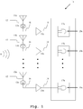
- the measurement system 1a comprises an antenna array with a plurality of antennas 11a,11b,...,11n configured to provide a voltage gain 12 corresponding to a received radio signal 14. Furthermore, the measurement system 1a comprises a plurality of radio frequency detectors 13a,13b,...,13n configured to rectify the voltage gain 12 from each antenna of the plurality of antennas 11a,11b,...,11n.
- the antenna array can be, by way of example, a form of phased array configured to perform constructive and/or destructive interference when receiving the radio signal 14 and each antenna of the plurality of antennas 11a,11b,...,11n provides a corresponding voltage gain to the subsequently connected plurality of radio frequency detectors 13a,13b,...,13n for rectification.
- the said subsequent connection can be implemented by means of transmission lines, for instance via coaxial cables.
- the measurement system 1a comprises a plurality of amplifiers 15a,15b,...,15n downstream of the plurality of radio frequency detectors 13a,13b,...13n configured to amplify the magnitude of a rectified voltage 16 from each of the radio frequency detectors 13a, 13b, ..., 13n.
- the measurement system 1a moreover comprises a plurality of receiving elements 17a,17b,...,17n, each includes a light emitting diode 19a,19b,...,19n and configured to receive an amplified voltage 18 corresponding to each amplifier of the plurality of amplifiers 15a,15b,...,15n.
- the light emitting diodes are generally RGB light emitting diodes, preferably multi-color light emitting diodes that can emit at least three different colors. Alternatively, at least three separate light emitting diodes with different color can be incorporated instead of a single multi-color light emitting diode.
- the measurement system 1a provides a simple and cost-effective scheme to optically visualize the radiation pattern in real-time.
- a second exemplary embodiment of the inventive measurement system 1b for real-time visualization of radiation pattern is illustrated.
- the respective measurement system 1b is based on the above-mentioned first exemplary embodiment 1a and additionally comprises tuning elements 21a,21b,...,21n configured to adjust the amplified voltage 18 of each amplifier of the plurality of amplifiers 15a,15b,...,15n corresponding to an input voltage range of the light emitting diode 19a,19b,...,19n associated with it.
- the tuning element 21a,21b,...,21n is further configured to assign different intensity levels for the amplified voltage 18 corresponding to different colors of the light emitting diode 19a,19b,...,19n and the light emitting diode 19a,19b,...,19n is configured to code the intensity levels of the amplified voltage 18 with respect to different colors.
- the tuning elements 21a,21b,...,21n may comprise adjustable positive linear voltage regulators that vary the rectified and successively amplified voltages with respect to an internal reference voltage.
- the internal reference voltage can be selected, for instance, according to the minimum drive voltage for the light emitting diodes 19a,19b,...,19n.
- the regulated voltage levels are then categorized in at least three reference voltage levels with respect to drive voltage levels required by the light emitting diodes 19a,19b,...,19n to radiate corresponding colors.
- RED color can be associated with the high voltage levels and can be translated as high radiation intensity
- BLUE color can be associated with the low voltage levels and can be translated as low radiation intensity and so on.
- the system does not require trained personal to conduct measurements.
- a third exemplary embodiment of the inventive measurement system 1b for real-time visualization of radiation pattern is illustrated.
- the respective measurement system 1c is based on the second exemplary embodiment 1b and further comprises a reference antenna 33, wherein a reference color mapping is observed with respect to the intensity levels for a known radiation pattern of the reference antenna 33 in a reference environment with a reference antenna distance.
- each amplifier of the plurality of amplifiers 15a,15b,...,15n is calibrated by adjusting the intensity levels with respect to the reference color mapping.
- Each amplifier 15a,15b,...,15n is calibrated separately through the tuning elements 21a,21b,...,21n to provide acceptable signal intensity to drive the associated light emitting diode 19a,19b,...,19n and thereby gives the right color corresponding to the known antenna pattern, for instance RED for high radiation intensity, BLUE for low radiation intensity and so on.
- the observation of the reference color mapping is performed with a camera.
- the antennas 11a,11b,...,11n, radio frequency detectors 13a,13b,...,13n, amplifiers 15a,15b,...,15n and receiving elements 17a,17b,...,17n are arranged in pixels and the camera is further configured to film the pixels and visually displays the measured radiation pattern in real-time.
- it is also possible to observe and compare the radiation intensity levels by implementing analog-to-digital converters, wherein the corresponding voltage levels are preferably displayed in real-time via graphical representation and/or tabular form.
- the measurement data corresponding to the reference color mapping can be stored in a memory location and can be utilized before and/or during the measurement for calibrating the amplifiers 15a,15b,...,15n.
- a flow chart of an exemplary embodiment of the inventive measurement method for real-time visualization of radiation pattern is illustrated.
- a voltage gain from each antenna of the plurality of antennas corresponding to a received radio signal is obtained.
- the corresponding received voltage gain is rectified.
- the magnitude of a rectified voltage from each of the radio frequency detectors is amplified.
- an amplified voltage from each amplifier of the plurality of amplifiers downstream of the plurality of radio frequency detectors is received.
- a fifth step S5 the amplified voltage of each amplifier of the plurality of amplifiers is adjusted corresponding to an input voltage range of the light emitting diode associated with it.
- a sixth step S6 different intensity levels for the amplified voltage are assigned corresponding to different colors of the light emitting diode.
- the intensity levels of the amplified voltage are coded with respect to different colors of the light emitting diode.
- a reference color mapping is observed with respect to the intensity levels for a known radiation pattern of the reference antenna in a reference environment with a reference antenna distance.
- each amplifier of the plurality of amplifiers is calibrated by adjusting the intensity levels with respect to the reference color mapping.
- the antennas, radio frequency detectors, amplifiers and receiving elements are arranged in pixels.
- the pixels are filmed and the measured radiation pattern is displayed visually in real-time.
Landscapes
- Physics & Mathematics (AREA)
- General Physics & Mathematics (AREA)
- Electromagnetism (AREA)
- Engineering & Computer Science (AREA)
- Power Engineering (AREA)
- Computer Networks & Wireless Communication (AREA)
- Signal Processing (AREA)
- Condensed Matter Physics & Semiconductors (AREA)
- Variable-Direction Aerials And Aerial Arrays (AREA)
- Testing, Inspecting, Measuring Of Stereoscopic Televisions And Televisions (AREA)
Abstract
Description
- The invention relates to a measurement system and a corresponding measurement method for real-time visualization of radiation pattern, especially to perform measurements on radio frequency radiation to assess the signal strength and the radiation direction of the receiving signal.
- For measuring radiation patterns, mechanically moving measuring probes are commonly used, which are moved in a lateral direction along the measurement axes and the corresponding radiation strength levels are sampled. Instead of the point by point measurement as described above, it is also possible to measure a radiation pattern by using a fixed measuring probe and by moving the device under test in a lateral direction with respect to the measurement axes.
- For example,
CN 105242169 B demonstrates a measuring apparatus for a signal transmitting terminal and a signal receiving terminal of a distribution frame. The apparatus comprises a housing, a testing connector and a detection module arranged in the housing. The testing connector is further connected via lead outside of the housing to obtain measurements from points to be tested. - However, utilizing measurement probes to get sampled data, disadvantageously, require a subsequent evaluation logic that involves additional processing time and consequently the system fails to perform real-time measurement. Accordingly, there is the object to provide a measurement system and a corresponding measurement method for real-time visualization of radiation pattern as well as to perform real-time measurements in a simplified manner. The object is solved by the features of the first independent claim regarding the measurement system and by the features of the second independent claim regarding the measurement method. The dependent claims comprise further developments.
- According to a first aspect of the invention, a measurement system for real-time visualization of radiation pattern is provided. The measurement system comprises an antenna array with a plurality of antennas configured to provide a voltage gain corresponding to a received radio signal. Furthermore, the measurement system comprises a plurality of radio frequency detectors configured to rectify the voltage gain from each antenna of the plurality of antennas. Advantageously, the measurement system operates on the rectified voltages corresponding to the received radio frequency signal levels and therefore leads to a simplified processing scheme. In addition, the measurement system comprises a plurality of amplifiers downstream of the plurality of radio frequency detectors configured to amplify the magnitude of a rectified voltage from each of the radio frequency detectors. The measurement system moreover comprises a plurality of receiving elements, each includes a light emitting diode and configured to receive an amplified voltage corresponding to each amplifier of the plurality of amplifiers. By way of these light emitting diodes, the measurement system is configured to optically visualize the radiation pattern in real-time, which further enables simple assessment of the measured signal strength.
- In this context, it is particularly advantageous if the light emitting diode is a RGB light emitting diode, preferably a multi-color light emitting diode, configured to emit at least three different colors. Hence, a simplified and low cost measure is implemented for differentiating the radiation pattern.
- According to a first preferred implementation form of said first aspect of the invention, the measurement system further comprises tuning elements configured to adjust the amplified voltage of each amplifier of the plurality of amplifiers corresponding to an input voltage range of the light emitting diode associated with it. Advantageously, the driving voltages for the light emitting diodes are adjusted separately before or during the measurement at each of the amplifier output, which significantly improves system reliability.
- Moreover, the tuning element is further configured to assign different intensity levels for the amplified voltage corresponding to different colors of the light emitting diode and wherein the light emitting diode is configured to code the intensity levels of the amplified voltage with respect to different colors. Advantageously, the measured signal strengths are visually differentiable by way of the radiated colors, for instance, red denotes high signal strength, green denotes medium signal strength and so on.
- According to a second preferred implementation form of said first aspect of the invention, the measurement system further comprises a reference antenna, wherein a reference color mapping is observed with respect to the intensity levels for a known radiation pattern of the reference antenna in a reference environment with a reference antenna distance. In this context, each amplifier of the plurality of amplifiers is calibrated by adjusting the intensity levels with respect to the reference color mapping. Advantageously, each amplifier is calibrated separately to provide acceptable signal intensity to drive the associated light emitting diode and thereby gives right color corresponding to the known antenna pattern, which significantly improves measurement accuracy.
- According to a further preferred implementation form of said first aspect of the invention, the observation of the reference color mapping is performed with a camera. In this context, the antennas, radio frequency detectors, amplifiers and receiving elements are arranged in pixels and wherein the camera is further configured to film the pixels and visually displays the measured radiation pattern in real-time. Advantageously, a simplified observation scheme is implemented where a camera films the pixels with different radiated colors corresponding to different radiation strength.
- According to a second aspect of the invention, a measurement method for real-time visualization of radiation pattern in a measurement system comprising an antenna array with a plurality of antennas, a plurality of radio frequency detectors, a plurality of amplifiers and a plurality of receiving elements including light emitting diodes is provided. The measurement method comprises the steps of obtaining a voltage gain from each antenna of the plurality of antennas corresponding to a received radio signal, rectifying the voltage gain, amplifying the magnitude of a rectified voltage from each of the radio frequency detectors, and receiving an amplified voltage from each amplifier of the plurality of amplifiers downstream of the plurality of radio frequency detectors. Advantageously, the method provides a simplified processing scheme that operates on the rectified voltages corresponding to the received radio frequency signal levels and thereby enables simple assessment of the measured signal strength by way of the light emitting diodes by optically visualizing the radiation pattern in real-time.
- In this context, it is particularly advantageous if the light emitting diode is a RGB light emitting diode, preferably a multi-color light emitting diode, configured to emit at least three different colors. Hence, a simplified and low cost measure is implemented for differentiating the radiation pattern.
- According to a first preferred implementation form of said second aspect of the invention, the measurement method further comprises the step of adjusting the amplified voltage of each amplifier of the plurality of amplifiers corresponding to an input voltage range of the light emitting diode associated with it. Advantageously, the driving voltages for the light emitting diodes are adjusted separately before or during the measurement at each of the amplifier output, which significantly improves system reliability.
- Moreover, the measurement method further comprises the steps of assigning different intensity levels for the amplified voltage corresponding to different colors of the light emitting diode and coding the intensity levels of the amplified voltage with respect to different colors of the light emitting diode. Advantageously, the measured signal strengths are visually differentiable by way of the radiated colors, for instance, red denotes high signal strength, green denotes medium signal strength and so on.
- According to a second preferred implementation form of said second aspect of the invention, the measurement system further comprises a reference antenna and wherein the measurement method further comprises the steps of observing a reference color mapping with respect to the intensity levels for a known radiation pattern of the reference antenna in a reference environment with a reference antenna distance and calibrating each amplifier of the plurality of amplifiers by adjusting the intensity levels with respect to the reference color mapping. Advantageously, each amplifier is calibrated separately to provide acceptable signal intensity to drive the associated light emitting diode and thereby gives right color corresponding to the known antenna pattern, which significantly improves measurement accuracy.
- According to a further preferred implementation form of said second aspect of the invention, the observation of the reference color mapping is performed with a camera and the measurement method further comprises the steps of arranging the antennas, radio frequency detectors, amplifiers and receiving elements in pixels and filming the pixels and visually displaying the measured radiation pattern in real-time. Advantageously, a simplified observation scheme is implemented where a camera films the pixels with different radiated colors corresponding to different radiation strength.
- Exemplary embodiments of the invention are now further explained with respect to the drawings by way of example only, and not for limitation. In the drawings:
- Fig. 1
- shows an exemplary embodiment of the first aspect of the invention,
- Fig. 2
- shows a second exemplary embodiment of the first aspect of the invention,
- Fig. 3
- shows a third exemplary embodiment of the first aspect of the invention, and
- Fig. 4
- shows a flow chart of an exemplary embodiment of the second aspect of the invention.
- Reference will now be made in detail to the embodiments of the present invention, examples of which are illustrated in the accompanying drawings. Similar entities and reference numbers in different figures have been partially omitted. However, the following embodiments of the present invention may be variously modified and the range of the present invention is not limited by the following embodiments.
- In
Fig. 1 , an exemplary embodiment of the inventive measurement system 1a for real-time visualization of radiation pattern is illustrated. In this context, the measurement system 1a comprises an antenna array with a plurality ofantennas voltage gain 12 corresponding to a receivedradio signal 14. Furthermore, the measurement system 1a comprises a plurality ofradio frequency detectors voltage gain 12 from each antenna of the plurality ofantennas radio signal 14 and each antenna of the plurality ofantennas radio frequency detectors antenna radio frequency detector 113a,13b,...,13n as a single element on the antenna array. - In addition, the measurement system 1a comprises a plurality of
amplifiers radio frequency detectors voltage 16 from each of theradio frequency detectors elements light emitting diode voltage 18 corresponding to each amplifier of the plurality ofamplifiers light emitting diodes - In
Fig. 2 , a second exemplary embodiment of theinventive measurement system 1b for real-time visualization of radiation pattern is illustrated. Therespective measurement system 1b is based on the above-mentioned first exemplary embodiment 1a and additionally comprises tuningelements voltage 18 of each amplifier of the plurality ofamplifiers light emitting diode tuning element voltage 18 corresponding to different colors of thelight emitting diode light emitting diode voltage 18 with respect to different colors. By way of example, thetuning elements light emitting diodes - Since, it is possible to receive different radiation intensity at
different antennas tuning elements amplifiers light emitting diodes - In
Fig. 3 , a third exemplary embodiment of theinventive measurement system 1b for real-time visualization of radiation pattern is illustrated. Therespective measurement system 1c is based on the secondexemplary embodiment 1b and further comprises areference antenna 33, wherein a reference color mapping is observed with respect to the intensity levels for a known radiation pattern of thereference antenna 33 in a reference environment with a reference antenna distance. In this context, each amplifier of the plurality ofamplifiers amplifier tuning elements light emitting diode - Preferably, the observation of the reference color mapping is performed with a camera. In this context, the
antennas radio frequency detectors amplifiers elements amplifiers - In
Fig. 4 , a flow chart of an exemplary embodiment of the inventive measurement method for real-time visualization of radiation pattern is illustrated. In a first step S1, a voltage gain from each antenna of the plurality of antennas corresponding to a received radio signal is obtained. In a second step S2, the corresponding received voltage gain is rectified. In a third step S3, the magnitude of a rectified voltage from each of the radio frequency detectors is amplified. In a fourth step S4, an amplified voltage from each amplifier of the plurality of amplifiers downstream of the plurality of radio frequency detectors is received. - Then, in a fifth step S5, the amplified voltage of each amplifier of the plurality of amplifiers is adjusted corresponding to an input voltage range of the light emitting diode associated with it. In a sixth step S6, different intensity levels for the amplified voltage are assigned corresponding to different colors of the light emitting diode. In a seventh step S7, the intensity levels of the amplified voltage are coded with respect to different colors of the light emitting diode.
- Furthermore, in an eighth step S8, a reference color mapping is observed with respect to the intensity levels for a known radiation pattern of the reference antenna in a reference environment with a reference antenna distance. In a ninth step S9, each amplifier of the plurality of amplifiers is calibrated by adjusting the intensity levels with respect to the reference color mapping.
- Moreover, in a tenth step S10, the antennas, radio frequency detectors, amplifiers and receiving elements are arranged in pixels. Finally, in an eleventh step S11, the pixels are filmed and the measured radiation pattern is displayed visually in real-time.
- While various embodiments of the present invention have been described above, it should be understood that they have been presented by way of example only, and not limitation. Numerous changes to the disclosed embodiments can be made in accordance with the disclosure herein without departing from the spirit or scope of the invention. Thus, the breadth and scope of the present invention should not be limited by any of the above described embodiments. Rather, the scope of the invention should be defined in accordance with the following claims and their equivalents.
- Although the invention has been illustrated and described with respect to one or more implementations, equivalent alterations and modifications will occur to others skilled in the art upon the reading and understanding of this specification and the annexed drawings. In addition, while a particular feature of the invention may have been disclosed with respect to only one of several implementations, such feature may be combined with one or more other features of the other implementations as may be desired and advantageous for any given or particular application.
Claims (20)
- A measurement system for real-time visualization of radiation pattern comprising:- an antenna array with a plurality of antennas configured to provide a voltage gain corresponding to a received radio signal,- a plurality of radio frequency detectors configured to rectify the voltage gain from each antenna of the plurality of antennas,- a plurality of amplifiers downstream of the plurality of radio frequency detectors configured to amplify the magnitude of a rectified voltage from each of the radio frequency detectors, and- a plurality of receiving elements, each includes a light emitting diode and configured to receive an amplified voltage corresponding to each amplifier of the plurality of amplifiers.
- The measurement system according to claim 1,
wherein the light emitting diode is a RGB light emitting diode, preferably a multi-color light emitting diode, configured to emit at least three different colors. - The measurement system according to claim 1,
wherein the measurement system further comprises tuning elements configured to adjust the amplified voltage of each amplifier of the plurality of amplifiers corresponding to an input voltage range of the light emitting diode associated with it. - The measurement system according to claim 3,
wherein the tuning element is further configured to assign different intensity levels for the amplified voltage corresponding to different colors of the light emitting diode. - The measurement system according to claim 4,
wherein the light emitting diode is configured to code the intensity levels of the amplified voltage with respect to different colors. - The measurement system according to claim 1,
wherein the measurement system further comprises a reference antenna, wherein a reference color mapping is observed with respect to the intensity levels for a known radiation pattern of the reference antenna in a reference environment with a reference antenna distance. - The measurement system according to claim 6,
wherein each amplifier of the plurality of amplifiers is calibrated by adjusting the intensity levels with respect to the reference color mapping. - The measurement system according to claim 6,
wherein the observation of the reference color mapping is performed with a camera. - The measurement system according to claim 1,
wherein the antennas, radio frequency detectors, amplifiers and receiving elements are arranged in pixels. - The measurement system according to claim 9,
wherein the camera is further configured to film the pixels and visually displays the measured radiation pattern in real-time. - A measurement method for real-time visualization of radiation pattern in a measurement system comprising an antenna array with a plurality of antennas, a plurality of radio frequency detectors, a plurality of amplifiers and a plurality of receiving elements including light emitting diodes comprises the steps of:- obtaining a voltage gain from each antenna of the plurality of antennas corresponding to a received radio signal,- rectifying the voltage gain,- amplifying the magnitude of a rectified voltage from each of the radio frequency detectors, and- receiving an amplified voltage from each amplifier of the plurality of amplifiers downstream of the plurality of radio frequency detectors.
- The measurement method according to claim 11,
wherein the light emitting diode is a RGB light emitting diode, preferably a multi-color light emitting diode, configured to emit at least three different colors. - The measurement method according to claim 11,
wherein the measurement method further comprises the step of adjusting the amplified voltage of each amplifier of the plurality of amplifiers corresponding to an input voltage range of the light emitting diode associated with it. - The measurement method according to claim 11,
wherein the measurement method further comprises the step of assigning different intensity levels for the amplified voltage corresponding to different colors of the light emitting diode. - The measurement method according to claim 11,
wherein the measurement method further comprises the step of coding the intensity levels of the amplified voltage with respect to different colors of the light emitting diode. - The measurement method according to claim 11,
wherein the measurement system further comprises a reference antenna and wherein the measurement method further comprises the step of observing a reference color mapping with respect to the intensity levels for a known radiation pattern of the reference antenna in a reference environment with a reference antenna distance. - The measurement method according to claim 16,
wherein the measurement method further comprises the step of calibrating each amplifier of the plurality of amplifiers by adjusting the intensity levels with respect to the reference color mapping. - The measurement method according to claim 16,
wherein the observation of the reference color mapping is performed with a camera. - The measurement method according to claim 11,
wherein the measurement method further comprises the step of arranging the antennas, radio frequency detectors, amplifiers and receiving elements in pixels. - The measurement method according to claim 19,
wherein the measurement method further comprises the step of filming the pixels and visually displaying the measured radiation pattern in real-time.
Applications Claiming Priority (1)
| Application Number | Priority Date | Filing Date | Title |
|---|---|---|---|
| US16/353,712 US10955450B2 (en) | 2019-03-14 | 2019-03-14 | System and method for real-time visualization of radiation pattern |
Publications (2)
| Publication Number | Publication Date |
|---|---|
| EP3709035A1 true EP3709035A1 (en) | 2020-09-16 |
| EP3709035B1 EP3709035B1 (en) | 2024-11-20 |
Family
ID=68732820
Family Applications (1)
| Application Number | Title | Priority Date | Filing Date |
|---|---|---|---|
| EP19212385.9A Active EP3709035B1 (en) | 2019-03-14 | 2019-11-29 | System and method for real-time visualization of radiation pattern |
Country Status (3)
| Country | Link |
|---|---|
| US (1) | US10955450B2 (en) |
| EP (1) | EP3709035B1 (en) |
| CN (1) | CN111693786B (en) |
Families Citing this family (2)
| Publication number | Priority date | Publication date | Assignee | Title |
|---|---|---|---|---|
| US11070300B2 (en) * | 2019-03-18 | 2021-07-20 | Apple Inc. | Test probes for phased antenna arrays |
| CN118041375A (en) * | 2022-11-11 | 2024-05-14 | 是德科技股份有限公司 | Rectenna arrays for detecting power radiation patterns of microwave or millimeter wave signals |
Citations (6)
| Publication number | Priority date | Publication date | Assignee | Title |
|---|---|---|---|---|
| US20110128016A1 (en) * | 2008-07-28 | 2011-06-02 | Satoshi Yagitani | Radio wave intensity measuring device and radio wave measuring system |
| CN204389600U (en) * | 2015-03-03 | 2015-06-10 | 方皓 | Electromagnetic wave detection device |
| CN105242169A (en) | 2015-10-30 | 2016-01-13 | 北京博望华科科技有限公司 | Determination apparatus for signal transmitting terminal and signal receiving terminal of distribution frame |
| US20160286406A1 (en) * | 2014-01-29 | 2016-09-29 | Softbank Corp. | Radio wave status indicating apparatus, communication apparatus and computer-readable medium |
| US10094855B1 (en) * | 2013-06-24 | 2018-10-09 | Peter Fuhr | Frequency visualization apparatus and method |
| US20190011487A1 (en) * | 2017-07-10 | 2019-01-10 | The Government of the United States of America, as represented by the Secretary of Homeland Security | Electromagnetic radiation detection apparatus and method of detecting low levels of millimeter wave electromagnetic radiation |
Family Cites Families (11)
| Publication number | Priority date | Publication date | Assignee | Title |
|---|---|---|---|---|
| DE10056472A1 (en) * | 2000-11-15 | 2002-05-29 | Infineon Technologies Ag | Polar loop transmission circuit |
| US7116948B2 (en) * | 2003-04-25 | 2006-10-03 | Broadcom Corporation | High-speed signal power detection circuit |
| US20050057298A1 (en) * | 2003-09-16 | 2005-03-17 | Kevin Gamble | Demodulating logarithmic amplifier and method of amplification |
| CN100562752C (en) * | 2006-11-17 | 2009-11-25 | 中国舰船研究设计中心 | Predicted method of radiation field strength mode of short wave antenna |
| CN101354412A (en) * | 2008-08-28 | 2009-01-28 | 深圳华为通信技术有限公司 | Apparatus for testing electromagnetic radiation strength |
| CN101464483A (en) * | 2008-11-10 | 2009-06-24 | 电子科技大学 | Portable passive electromagnetic radiation detector |
| EP2760176A1 (en) | 2013-01-23 | 2014-07-30 | Vodafone Holding GmbH | Flash video enabler for iOS devices |
| CN203672979U (en) * | 2013-12-28 | 2014-06-25 | 黄宇嵩 | Electromagnetic radiation monitoring device |
| EP3252445B1 (en) * | 2016-06-01 | 2024-01-03 | ams International AG | Photodetector arrangement having an adjustable output and method for adjusting an output of a photodetector arrangement |
| KR101958311B1 (en) * | 2017-01-12 | 2019-03-15 | 국방과학연구소 | System for calculating antenna characteristics from measured antenna radiation patterns |
| WO2019231922A1 (en) * | 2018-05-31 | 2019-12-05 | Skyworks Solutions, Inc. | Apparatus and methods for multi-antenna communications |
-
2019
- 2019-03-14 US US16/353,712 patent/US10955450B2/en active Active
- 2019-11-29 EP EP19212385.9A patent/EP3709035B1/en active Active
-
2020
- 2020-01-14 CN CN202010036118.5A patent/CN111693786B/en active Active
Patent Citations (6)
| Publication number | Priority date | Publication date | Assignee | Title |
|---|---|---|---|---|
| US20110128016A1 (en) * | 2008-07-28 | 2011-06-02 | Satoshi Yagitani | Radio wave intensity measuring device and radio wave measuring system |
| US10094855B1 (en) * | 2013-06-24 | 2018-10-09 | Peter Fuhr | Frequency visualization apparatus and method |
| US20160286406A1 (en) * | 2014-01-29 | 2016-09-29 | Softbank Corp. | Radio wave status indicating apparatus, communication apparatus and computer-readable medium |
| CN204389600U (en) * | 2015-03-03 | 2015-06-10 | 方皓 | Electromagnetic wave detection device |
| CN105242169A (en) | 2015-10-30 | 2016-01-13 | 北京博望华科科技有限公司 | Determination apparatus for signal transmitting terminal and signal receiving terminal of distribution frame |
| US20190011487A1 (en) * | 2017-07-10 | 2019-01-10 | The Government of the United States of America, as represented by the Secretary of Homeland Security | Electromagnetic radiation detection apparatus and method of detecting low levels of millimeter wave electromagnetic radiation |
Also Published As
| Publication number | Publication date |
|---|---|
| US10955450B2 (en) | 2021-03-23 |
| CN111693786B (en) | 2024-11-29 |
| US20200292605A1 (en) | 2020-09-17 |
| EP3709035B1 (en) | 2024-11-20 |
| CN111693786A (en) | 2020-09-22 |
Similar Documents
| Publication | Publication Date | Title |
|---|---|---|
| US9547066B2 (en) | Calibration of an antenna array | |
| EP3054273B1 (en) | Colorimetry system for display testing | |
| RU2543557C2 (en) | System of simulation of electromagnetic environment with network of multiple probes | |
| EP3709035B1 (en) | System and method for real-time visualization of radiation pattern | |
| CN107959515B (en) | Method and device for measuring noise power of multiple antennas | |
| KR102581850B1 (en) | Method and apparatus for generating compensation data of display panel | |
| US9392479B2 (en) | Pocket-size PIM inspector | |
| CN112033542B (en) | Brightness and chrominance measuring method, device and equipment and readable storage medium | |
| KR20110100145A (en) | Color-unevenness inspection apparatus and method | |
| CN102565556A (en) | Display for real-time visualization of radiation pattern and display method thereof | |
| JP5351466B2 (en) | Radio source visualization device | |
| US20240344975A1 (en) | Colorimetry method and system | |
| US8106946B2 (en) | Circuitry testing method and circuitry testing device | |
| KR20200027263A (en) | apparatus and method for canceling cross component in testing wireless device with multiple antenna | |
| CN110161540B (en) | Self-calibration method of RDSS user machine closed-loop test system | |
| CN115877092B (en) | A visualization system and method for monitoring the electromagnetic environment in space | |
| JP4944636B2 (en) | Linear array antenna near-radiation electric field measurement apparatus and method | |
| US20110098959A1 (en) | Multi-point calibration method for the depth of a horizontal directional drilling guiding instrument | |
| JP2010078418A (en) | Spectral measurement apparatus, calibration apparatus, spectral measurement method and calibration method | |
| JP2007093477A (en) | Color measuring device calibration method and calibration device, color measuring method, color measuring device | |
| CN101741478B (en) | Method and device for testing receiving sensitivity of load modulation signal | |
| CN104157242A (en) | OLED display digital modulation method | |
| JP2010139356A (en) | Calibrating function acquiring system and testing system of display | |
| CN110873825B (en) | Method for determining a faulty DUT antenna and measurement system | |
| US11226360B2 (en) | Over-the-air test system and method with visual status indication |
Legal Events
| Date | Code | Title | Description |
|---|---|---|---|
| PUAI | Public reference made under article 153(3) epc to a published international application that has entered the european phase |
Free format text: ORIGINAL CODE: 0009012 |
|
| STAA | Information on the status of an ep patent application or granted ep patent |
Free format text: STATUS: THE APPLICATION HAS BEEN PUBLISHED |
|
| AK | Designated contracting states |
Kind code of ref document: A1 Designated state(s): AL AT BE BG CH CY CZ DE DK EE ES FI FR GB GR HR HU IE IS IT LI LT LU LV MC MK MT NL NO PL PT RO RS SE SI SK SM TR |
|
| AX | Request for extension of the european patent |
Extension state: BA ME |
|
| STAA | Information on the status of an ep patent application or granted ep patent |
Free format text: STATUS: REQUEST FOR EXAMINATION WAS MADE |
|
| 17P | Request for examination filed |
Effective date: 20201118 |
|
| RBV | Designated contracting states (corrected) |
Designated state(s): AL AT BE BG CH CY CZ DE DK EE ES FI FR GB GR HR HU IE IS IT LI LT LU LV MC MK MT NL NO PL PT RO RS SE SI SK SM TR |
|
| STAA | Information on the status of an ep patent application or granted ep patent |
Free format text: STATUS: EXAMINATION IS IN PROGRESS |
|
| 17Q | First examination report despatched |
Effective date: 20221122 |
|
| P01 | Opt-out of the competence of the unified patent court (upc) registered |
Effective date: 20230525 |
|
| GRAP | Despatch of communication of intention to grant a patent |
Free format text: ORIGINAL CODE: EPIDOSNIGR1 |
|
| STAA | Information on the status of an ep patent application or granted ep patent |
Free format text: STATUS: GRANT OF PATENT IS INTENDED |
|
| INTG | Intention to grant announced |
Effective date: 20240717 |
|
| GRAS | Grant fee paid |
Free format text: ORIGINAL CODE: EPIDOSNIGR3 |
|
| GRAA | (expected) grant |
Free format text: ORIGINAL CODE: 0009210 |
|
| STAA | Information on the status of an ep patent application or granted ep patent |
Free format text: STATUS: THE PATENT HAS BEEN GRANTED |
|
| AK | Designated contracting states |
Kind code of ref document: B1 Designated state(s): AL AT BE BG CY CZ DE DK EE ES FI FR GB GR HR HU IS IT LT LU LV MC MK MT NL NO PL PT RO RS SE SI SK SM TR |
|
| RBV | Designated contracting states (corrected) |
Designated state(s): AL AT BE BG CY CZ DE DK EE ES FI FR GB GR HR HU IS IT LT LU LV MC MK MT NL NO PL PT RO RS SE SI SK SM TR |
|
| REG | Reference to a national code |
Ref country code: GB Ref legal event code: FG4D |
|
| REG | Reference to a national code |
Ref country code: DE Ref legal event code: R096 Ref document number: 602019062160 Country of ref document: DE |
|
| REG | Reference to a national code |
Ref country code: LT Ref legal event code: MG9D |
|
| REG | Reference to a national code |
Ref country code: NL Ref legal event code: MP Effective date: 20241120 |
|
| PG25 | Lapsed in a contracting state [announced via postgrant information from national office to epo] |
Ref country code: HR Free format text: LAPSE BECAUSE OF FAILURE TO SUBMIT A TRANSLATION OF THE DESCRIPTION OR TO PAY THE FEE WITHIN THE PRESCRIBED TIME-LIMIT Effective date: 20241120 Ref country code: PT Free format text: LAPSE BECAUSE OF FAILURE TO SUBMIT A TRANSLATION OF THE DESCRIPTION OR TO PAY THE FEE WITHIN THE PRESCRIBED TIME-LIMIT Effective date: 20250320 Ref country code: IS Free format text: LAPSE BECAUSE OF FAILURE TO SUBMIT A TRANSLATION OF THE DESCRIPTION OR TO PAY THE FEE WITHIN THE PRESCRIBED TIME-LIMIT Effective date: 20250320 |
|
| PG25 | Lapsed in a contracting state [announced via postgrant information from national office to epo] |
Ref country code: NL Free format text: LAPSE BECAUSE OF FAILURE TO SUBMIT A TRANSLATION OF THE DESCRIPTION OR TO PAY THE FEE WITHIN THE PRESCRIBED TIME-LIMIT Effective date: 20241120 Ref country code: FI Free format text: LAPSE BECAUSE OF FAILURE TO SUBMIT A TRANSLATION OF THE DESCRIPTION OR TO PAY THE FEE WITHIN THE PRESCRIBED TIME-LIMIT Effective date: 20241120 |
|
| REG | Reference to a national code |
Ref country code: AT Ref legal event code: MK05 Ref document number: 1744033 Country of ref document: AT Kind code of ref document: T Effective date: 20241120 |
|
| PG25 | Lapsed in a contracting state [announced via postgrant information from national office to epo] |
Ref country code: BG Free format text: LAPSE BECAUSE OF FAILURE TO SUBMIT A TRANSLATION OF THE DESCRIPTION OR TO PAY THE FEE WITHIN THE PRESCRIBED TIME-LIMIT Effective date: 20241120 |
|
| PG25 | Lapsed in a contracting state [announced via postgrant information from national office to epo] |
Ref country code: ES Free format text: LAPSE BECAUSE OF FAILURE TO SUBMIT A TRANSLATION OF THE DESCRIPTION OR TO PAY THE FEE WITHIN THE PRESCRIBED TIME-LIMIT Effective date: 20241120 |
|
| PG25 | Lapsed in a contracting state [announced via postgrant information from national office to epo] |
Ref country code: NO Free format text: LAPSE BECAUSE OF FAILURE TO SUBMIT A TRANSLATION OF THE DESCRIPTION OR TO PAY THE FEE WITHIN THE PRESCRIBED TIME-LIMIT Effective date: 20250220 |
|
| PG25 | Lapsed in a contracting state [announced via postgrant information from national office to epo] |
Ref country code: AT Free format text: LAPSE BECAUSE OF FAILURE TO SUBMIT A TRANSLATION OF THE DESCRIPTION OR TO PAY THE FEE WITHIN THE PRESCRIBED TIME-LIMIT Effective date: 20241120 Ref country code: GR Free format text: LAPSE BECAUSE OF FAILURE TO SUBMIT A TRANSLATION OF THE DESCRIPTION OR TO PAY THE FEE WITHIN THE PRESCRIBED TIME-LIMIT Effective date: 20250221 Ref country code: LV Free format text: LAPSE BECAUSE OF FAILURE TO SUBMIT A TRANSLATION OF THE DESCRIPTION OR TO PAY THE FEE WITHIN THE PRESCRIBED TIME-LIMIT Effective date: 20241120 |
|
| PG25 | Lapsed in a contracting state [announced via postgrant information from national office to epo] |
Ref country code: PL Free format text: LAPSE BECAUSE OF FAILURE TO SUBMIT A TRANSLATION OF THE DESCRIPTION OR TO PAY THE FEE WITHIN THE PRESCRIBED TIME-LIMIT Effective date: 20241120 |
|
| PG25 | Lapsed in a contracting state [announced via postgrant information from national office to epo] |
Ref country code: RS Free format text: LAPSE BECAUSE OF FAILURE TO SUBMIT A TRANSLATION OF THE DESCRIPTION OR TO PAY THE FEE WITHIN THE PRESCRIBED TIME-LIMIT Effective date: 20250220 |
|
| PG25 | Lapsed in a contracting state [announced via postgrant information from national office to epo] |
Ref country code: SM Free format text: LAPSE BECAUSE OF FAILURE TO SUBMIT A TRANSLATION OF THE DESCRIPTION OR TO PAY THE FEE WITHIN THE PRESCRIBED TIME-LIMIT Effective date: 20241120 |
|
| PG25 | Lapsed in a contracting state [announced via postgrant information from national office to epo] |
Ref country code: DK Free format text: LAPSE BECAUSE OF FAILURE TO SUBMIT A TRANSLATION OF THE DESCRIPTION OR TO PAY THE FEE WITHIN THE PRESCRIBED TIME-LIMIT Effective date: 20241120 |
|
| PG25 | Lapsed in a contracting state [announced via postgrant information from national office to epo] |
Ref country code: LU Free format text: LAPSE BECAUSE OF NON-PAYMENT OF DUE FEES Effective date: 20241129 |
|
| PG25 | Lapsed in a contracting state [announced via postgrant information from national office to epo] |
Ref country code: EE Free format text: LAPSE BECAUSE OF FAILURE TO SUBMIT A TRANSLATION OF THE DESCRIPTION OR TO PAY THE FEE WITHIN THE PRESCRIBED TIME-LIMIT Effective date: 20241120 |
|
| PG25 | Lapsed in a contracting state [announced via postgrant information from national office to epo] |
Ref country code: RO Free format text: LAPSE BECAUSE OF FAILURE TO SUBMIT A TRANSLATION OF THE DESCRIPTION OR TO PAY THE FEE WITHIN THE PRESCRIBED TIME-LIMIT Effective date: 20241120 |
|
| PG25 | Lapsed in a contracting state [announced via postgrant information from national office to epo] |
Ref country code: SK Free format text: LAPSE BECAUSE OF FAILURE TO SUBMIT A TRANSLATION OF THE DESCRIPTION OR TO PAY THE FEE WITHIN THE PRESCRIBED TIME-LIMIT Effective date: 20241120 |
|
| PG25 | Lapsed in a contracting state [announced via postgrant information from national office to epo] |
Ref country code: CZ Free format text: LAPSE BECAUSE OF FAILURE TO SUBMIT A TRANSLATION OF THE DESCRIPTION OR TO PAY THE FEE WITHIN THE PRESCRIBED TIME-LIMIT Effective date: 20241120 |
|
| PG25 | Lapsed in a contracting state [announced via postgrant information from national office to epo] |
Ref country code: IT Free format text: LAPSE BECAUSE OF FAILURE TO SUBMIT A TRANSLATION OF THE DESCRIPTION OR TO PAY THE FEE WITHIN THE PRESCRIBED TIME-LIMIT Effective date: 20241120 |
|
| REG | Reference to a national code |
Ref country code: DE Ref legal event code: R097 Ref document number: 602019062160 Country of ref document: DE |
|
| REG | Reference to a national code |
Ref country code: BE Ref legal event code: MM Effective date: 20241130 |
|
| PG25 | Lapsed in a contracting state [announced via postgrant information from national office to epo] |
Ref country code: SE Free format text: LAPSE BECAUSE OF FAILURE TO SUBMIT A TRANSLATION OF THE DESCRIPTION OR TO PAY THE FEE WITHIN THE PRESCRIBED TIME-LIMIT Effective date: 20241120 |
|
| PG25 | Lapsed in a contracting state [announced via postgrant information from national office to epo] |
Ref country code: MC Free format text: LAPSE BECAUSE OF FAILURE TO SUBMIT A TRANSLATION OF THE DESCRIPTION OR TO PAY THE FEE WITHIN THE PRESCRIBED TIME-LIMIT Effective date: 20241120 |
|
| PLBE | No opposition filed within time limit |
Free format text: ORIGINAL CODE: 0009261 |
|
| STAA | Information on the status of an ep patent application or granted ep patent |
Free format text: STATUS: NO OPPOSITION FILED WITHIN TIME LIMIT |
|
| PG25 | Lapsed in a contracting state [announced via postgrant information from national office to epo] |
Ref country code: BE Free format text: LAPSE BECAUSE OF NON-PAYMENT OF DUE FEES Effective date: 20241130 |
|
| 26N | No opposition filed |
Effective date: 20250821 |
|
| PGFP | Annual fee paid to national office [announced via postgrant information from national office to epo] |
Ref country code: DE Payment date: 20251118 Year of fee payment: 7 |
|
| PGFP | Annual fee paid to national office [announced via postgrant information from national office to epo] |
Ref country code: GB Payment date: 20251120 Year of fee payment: 7 |
|
| PGFP | Annual fee paid to national office [announced via postgrant information from national office to epo] |
Ref country code: FR Payment date: 20251120 Year of fee payment: 7 |
|
| PG25 | Lapsed in a contracting state [announced via postgrant information from national office to epo] |
Ref country code: HU Free format text: LAPSE BECAUSE OF FAILURE TO SUBMIT A TRANSLATION OF THE DESCRIPTION OR TO PAY THE FEE WITHIN THE PRESCRIBED TIME-LIMIT; INVALID AB INITIO Effective date: 20191129 |
|
| PG25 | Lapsed in a contracting state [announced via postgrant information from national office to epo] |
Ref country code: CY Free format text: LAPSE BECAUSE OF FAILURE TO SUBMIT A TRANSLATION OF THE DESCRIPTION OR TO PAY THE FEE WITHIN THE PRESCRIBED TIME-LIMIT; INVALID AB INITIO Effective date: 20191129 |
|
| PG25 | Lapsed in a contracting state [announced via postgrant information from national office to epo] |
Ref country code: TR Free format text: LAPSE BECAUSE OF FAILURE TO SUBMIT A TRANSLATION OF THE DESCRIPTION OR TO PAY THE FEE WITHIN THE PRESCRIBED TIME-LIMIT Effective date: 20241120 |
|
| PG25 | Lapsed in a contracting state [announced via postgrant information from national office to epo] |
Ref country code: SI Free format text: LAPSE BECAUSE OF FAILURE TO SUBMIT A TRANSLATION OF THE DESCRIPTION OR TO PAY THE FEE WITHIN THE PRESCRIBED TIME-LIMIT Effective date: 20241120 |
|
| PG25 | Lapsed in a contracting state [announced via postgrant information from national office to epo] |
Ref country code: LT Free format text: LAPSE BECAUSE OF FAILURE TO SUBMIT A TRANSLATION OF THE DESCRIPTION OR TO PAY THE FEE WITHIN THE PRESCRIBED TIME-LIMIT Effective date: 20241120 |