EP3708979A1 - Article supplying apparatus and combinatorial weighing device - Google Patents
Article supplying apparatus and combinatorial weighing device Download PDFInfo
- Publication number
- EP3708979A1 EP3708979A1 EP18876143.1A EP18876143A EP3708979A1 EP 3708979 A1 EP3708979 A1 EP 3708979A1 EP 18876143 A EP18876143 A EP 18876143A EP 3708979 A1 EP3708979 A1 EP 3708979A1
- Authority
- EP
- European Patent Office
- Prior art keywords
- article
- holding
- holding portion
- stand
- control
- Prior art date
- Legal status (The legal status is an assumption and is not a legal conclusion. Google has not performed a legal analysis and makes no representation as to the accuracy of the status listed.)
- Withdrawn
Links
Images



Classifications
-
- B—PERFORMING OPERATIONS; TRANSPORTING
- B65—CONVEYING; PACKING; STORING; HANDLING THIN OR FILAMENTARY MATERIAL
- B65G—TRANSPORT OR STORAGE DEVICES, e.g. CONVEYORS FOR LOADING OR TIPPING, SHOP CONVEYOR SYSTEMS OR PNEUMATIC TUBE CONVEYORS
- B65G65/00—Loading or unloading
- B65G65/005—Control arrangements
-
- G—PHYSICS
- G01—MEASURING; TESTING
- G01G—WEIGHING
- G01G19/00—Weighing apparatus or methods adapted for special purposes not provided for in the preceding groups
- G01G19/387—Weighing apparatus or methods adapted for special purposes not provided for in the preceding groups for combinatorial weighing, i.e. selecting a combination of articles whose total weight or number is closest to a desired value
- G01G19/393—Weighing apparatus or methods adapted for special purposes not provided for in the preceding groups for combinatorial weighing, i.e. selecting a combination of articles whose total weight or number is closest to a desired value using two or more weighing units
-
- B—PERFORMING OPERATIONS; TRANSPORTING
- B25—HAND TOOLS; PORTABLE POWER-DRIVEN TOOLS; MANIPULATORS
- B25J—MANIPULATORS; CHAMBERS PROVIDED WITH MANIPULATION DEVICES
- B25J9/00—Program-controlled manipulators
- B25J9/0093—Program-controlled manipulators co-operating with conveyor means
-
- B—PERFORMING OPERATIONS; TRANSPORTING
- B65—CONVEYING; PACKING; STORING; HANDLING THIN OR FILAMENTARY MATERIAL
- B65G—TRANSPORT OR STORAGE DEVICES, e.g. CONVEYORS FOR LOADING OR TIPPING, SHOP CONVEYOR SYSTEMS OR PNEUMATIC TUBE CONVEYORS
- B65G61/00—Use of pick-up or transfer devices or of manipulators for stacking or de-stacking articles not otherwise provided for
-
- G—PHYSICS
- G05—CONTROLLING; REGULATING
- G05B—CONTROL OR REGULATING SYSTEMS IN GENERAL; FUNCTIONAL ELEMENTS OF SUCH SYSTEMS; MONITORING OR TESTING ARRANGEMENTS FOR SUCH SYSTEMS OR ELEMENTS
- G05B19/00—Program-control systems
- G05B19/02—Program-control systems electric
- G05B19/418—Total factory control, i.e. centrally controlling a plurality of machines, e.g. direct or distributed numerical control [DNC], flexible manufacturing systems [FMS], integrated manufacturing systems [IMS] or computer integrated manufacturing [CIM]
- G05B19/41815—Total factory control, i.e. centrally controlling a plurality of machines, e.g. direct or distributed numerical control [DNC], flexible manufacturing systems [FMS], integrated manufacturing systems [IMS] or computer integrated manufacturing [CIM] characterised by the cooperation between machine tools, manipulators and conveyor or other workpiece supply system, workcell
- G05B19/4182—Total factory control, i.e. centrally controlling a plurality of machines, e.g. direct or distributed numerical control [DNC], flexible manufacturing systems [FMS], integrated manufacturing systems [IMS] or computer integrated manufacturing [CIM] characterised by the cooperation between machine tools, manipulators and conveyor or other workpiece supply system, workcell manipulators and conveyor only
-
- B—PERFORMING OPERATIONS; TRANSPORTING
- B25—HAND TOOLS; PORTABLE POWER-DRIVEN TOOLS; MANIPULATORS
- B25J—MANIPULATORS; CHAMBERS PROVIDED WITH MANIPULATION DEVICES
- B25J15/00—Gripping heads and other end effectors
- B25J15/0028—Gripping heads and other end effectors with movable, e.g. pivoting gripping jaw surfaces
-
- B—PERFORMING OPERATIONS; TRANSPORTING
- B25—HAND TOOLS; PORTABLE POWER-DRIVEN TOOLS; MANIPULATORS
- B25J—MANIPULATORS; CHAMBERS PROVIDED WITH MANIPULATION DEVICES
- B25J9/00—Program-controlled manipulators
- B25J9/0009—Constructional details, e.g. manipulator supports, bases
- B25J9/0018—Bases fixed on ceiling, i.e. upside down manipulators
-
- B—PERFORMING OPERATIONS; TRANSPORTING
- B65—CONVEYING; PACKING; STORING; HANDLING THIN OR FILAMENTARY MATERIAL
- B65G—TRANSPORT OR STORAGE DEVICES, e.g. CONVEYORS FOR LOADING OR TIPPING, SHOP CONVEYOR SYSTEMS OR PNEUMATIC TUBE CONVEYORS
- B65G2201/00—Indexing codes relating to handling devices, e.g. conveyors, characterised by the type of product or load being conveyed or handled
- B65G2201/02—Articles
- B65G2201/0202—Agricultural and processed food products
-
- B—PERFORMING OPERATIONS; TRANSPORTING
- B65—CONVEYING; PACKING; STORING; HANDLING THIN OR FILAMENTARY MATERIAL
- B65G—TRANSPORT OR STORAGE DEVICES, e.g. CONVEYORS FOR LOADING OR TIPPING, SHOP CONVEYOR SYSTEMS OR PNEUMATIC TUBE CONVEYORS
- B65G2814/00—Indexing codes relating to loading or unloading articles or bulk materials
- B65G2814/03—Loading or unloading means
- B65G2814/0344—Control or feeding or discharging using level or weight measuring means
-
- G—PHYSICS
- G01—MEASURING; TESTING
- G01G—WEIGHING
- G01G19/00—Weighing apparatus or methods adapted for special purposes not provided for in the preceding groups
- G01G19/387—Weighing apparatus or methods adapted for special purposes not provided for in the preceding groups for combinatorial weighing, i.e. selecting a combination of articles whose total weight or number is closest to a desired value
-
- G—PHYSICS
- G05—CONTROLLING; REGULATING
- G05B—CONTROL OR REGULATING SYSTEMS IN GENERAL; FUNCTIONAL ELEMENTS OF SUCH SYSTEMS; MONITORING OR TESTING ARRANGEMENTS FOR SUCH SYSTEMS OR ELEMENTS
- G05B2219/00—Program-control systems
- G05B2219/30—Nc systems
- G05B2219/31—From computer integrated manufacturing till monitoring
- G05B2219/31313—Measure weight, dimension and contents of box, tray
-
- Y—GENERAL TAGGING OF NEW TECHNOLOGICAL DEVELOPMENTS; GENERAL TAGGING OF CROSS-SECTIONAL TECHNOLOGIES SPANNING OVER SEVERAL SECTIONS OF THE IPC; TECHNICAL SUBJECTS COVERED BY FORMER USPC CROSS-REFERENCE ART COLLECTIONS [XRACs] AND DIGESTS
- Y02—TECHNOLOGIES OR APPLICATIONS FOR MITIGATION OR ADAPTATION AGAINST CLIMATE CHANGE
- Y02P—CLIMATE CHANGE MITIGATION TECHNOLOGIES IN THE PRODUCTION OR PROCESSING OF GOODS
- Y02P90/00—Enabling technologies with a potential contribution to greenhouse gas [GHG] emissions mitigation
- Y02P90/02—Total factory control, e.g. smart factories, flexible manufacturing systems [FMS] or integrated manufacturing systems [IMS]
Definitions
- the present disclosure relates to an article supplying apparatus and a combinatorial weighing device.
- Patent Literature 1 discloses a combinatorial weighing device in which articles weighed by weighing means are retained in a plurality of stock portions (containers) and combinatorial weighing targeting a plurality of articles retained in the plurality of stock portions is performed.
- a robot hand is utilized when an article is inserted into the stock portions.
- Patent Literature 1 Japanese Unexamined Patent Publication No. 2015-219190
- an article be able to be instantly inserted into a container after the article is held by a holding portion of a robot hand.
- a holding portion of a robot hand when another article is already retained in the container into which an article is to be inserted, there is a need to stand by until the container becomes empty while the article is held by the holding portion.
- the holding portion holding an article stand by at a position immediately above an article insertion port of the container.
- the holding portion holding portion stand by at a position immediately above an article insertion port of the container.
- An aspect of the present invention aims to maintain efficient article insertion and to appropriately perform the article insertion in an article supplying apparatus and a combinatorial weighing device utilizing a robot hand.
- an article supplying apparatus including a retention unit configured to retain an article serving as an insertion target, a robot hand configured to insert the article retained in the retention unit into a container, and a control unit configured to control operation of the robot hand.
- the robot hand has a holding portion for holding the article.
- the control unit is configured to execute holding control in which the article retained in the retention unit is held by the holding portion; and stand-by insertion control in which after the holding portion is temporarily disposed at a stand-by position different from a position immediately above an article insertion port in the container and set on a movement path from a start position of the holding through the holding control to the position immediately thereabove in a state in which the article is held by the holding portion, the holding portion is moved to the position immediately thereabove, and the article is inserted into the container via the article insertion port.
- this article supplying apparatus an article is held by the holding portion of the robot hand, and the holding portion is temporarily disposed at the stand-by position in this state. Thereafter, the holding portion is moved to the position immediately above the article insertion port (which will hereinafter be simply referred to as "a position immediately thereabove") in the container, and the article is inserted into the container via the article insertion port. Since the stand-by position is different from the position immediately thereabove, even if some articles slip out of the holding portion, erroneous insertion of some of the articles which have slipped out into the container can be curbed. Moreover, this stand-by position is set on the movement path from the start position of the holding through holding control to the position immediately thereabove.
- the time lag described above can be curbed, and efficient article insertion can be maintained. Therefore, in the article supplying apparatus utilizing the robot hand, efficient article insertion can be maintained and the article insertion can be appropriately performed.
- control unit may be configured to cause the holding portion to hold the article through the holding control and then determine whether or not the article is able to be inserted into the container, execute the stand-by insertion control when it is determined that the article is not able to be inserted into the container, and execute direct insertion control in which the holding portion is instantly moved to the position immediately thereabove without being temporarily disposed at the stand-by position and the article is inserted into the container via the article insertion port when it is determined that the article is able to be inserted into the container.
- the holding portion when an article is inserted into the container by the robot hand, the holding portion is not temporarily disposed at the stand-by position at all times, but an article is inserted into the container as it stands without causing the holding portion to be temporarily disposed at the stand-by position when an article can be inserted into the container.
- unnecessary stand-by of the holding portion can be curbed, and efficient article insertion can be realized.
- the stand-by position may be set at a position closer to the article insertion port than the start position of the holding through the holding control.
- the time lag described above can be curbed, and efficient article insertion can be maintained.
- the stand-by position may be set in a region adjacent to the article insertion port when viewed from above.
- the time lag described above can be further curbed, and efficient article insertion can be realized.
- a collection portion receiving the article which has fallen from the holding portion may be disposed below the stand-by position. In this configuration, an article which has slipped out of the holding portion during stand-by at the stand-by position can be collected.
- the stand-by position may be set at a height position higher than the article insertion port and between the retention unit and the article insertion port when viewed from above.
- the time lag described above can be further curbed, and efficient article insertion can be realized.
- a combinatorial weighing device including a retention unit configured to retain an article serving as an insertion target; a plurality of hoppers configured to allow the article to be inserted thereinto and to temporarily retain the article; a weighing unit configured to weigh each of a plurality of the articles retained in the plurality of hoppers; a robot hand configured to insert the article retained in the retention unit into the hopper; and a control unit configured to control operation of the robot hand, to select a plurality of the articles, of which a sum of weighing values becomes a target mass value set in advance, from the plurality of the articles weighed by the weighing unit, and to discharge the plurality of the selected articles from the hoppers.
- the robot hand has a holding portion for holding the article.
- the control unit is configured to execute holding control in which the article retained in the retention unit is held by the holding portion; and stand-by insertion control in which after the holding portion is temporarily disposed at a stand-by position different from a position immediately above an article insertion port in the hopper and set at a position closer to the article insertion port than a start position of holding through the holding control in a state in which the article is held by the holding portion through the holding control, the article is inserted into the hopper via the article insertion port.
- this combinatorial weighing device an article is held by the holding portion of the robot hand, and the holding portion is temporarily disposed at the stand-by position in this state. Thereafter, the holding portion is moved to the position immediately above the hopper, and the article is inserted into the hopper via the article insertion port. Since the stand-by position is different from the position immediately thereabove, even if some articles slip out of the holding portion, erroneous insertion of some of the articles which have slipped out into the hopper can be curbed. Moreover, this stand-by position is a position closer to the article insertion port than the start position of the holding through holding control.
- the time lag described above can be curbed, and efficient article insertion can be maintained. Therefore, in the combinatorial weighing device utilizing the robot hand, efficient article insertion can be maintained and the article insertion can be appropriately performed.
- a combinatorial weighing device 1 weighs articles (articles having uneven unit masses, such as agricultural products, aquatic products, and processed foods) supplied from the outside to achieve a target mass value and supplies the articles to a device such as a bag forming/packaging machine of a following stage, for example.
- the combinatorial weighing device 1 includes a retention unit 2, a plurality of pool hoppers 3, a plurality of weighing hoppers 4, a weighing unit 5, a robot hand 6, supplying conveyors 7, a control unit 8, a collection conveyor 9, and a collection box 10.
- a vertical direction is referred to as a Z direction
- a horizontal direction corresponding to a forward-rearward direction of the combinatorial weighing device 1 is referred to as a Y direction
- a horizontal direction perpendicular to the Y direction and the Z direction is referred to as an X direction.
- the retention unit 2 is a part for retaining articles (insertion targets) to be inserted into the pool hoppers 3.
- the retention unit 2 exhibits a rectangular box shape opening upward while having the X direction as its longitudinal direction.
- the retention unit 2 has a flat placement surface 2a. In the retention unit 2, an article supplied from the outside is placed on the placement surface 2a and is retained therein.
- the pool hopper 3 is a container into which an article is inserted by the robot hand 6.
- the pool hopper 3 exhibits a cup shape opening upward.
- the pool hoppers 3 are supported directly or indirectly by a frame F.
- the pool hoppers 3 are arranged side by side in the X direction at positions below the retention unit 2 and away from the retention unit 2 in the Y direction.
- An upper edge of the pool hopper 3 constitutes an article insertion port 3a through which an article is inserted.
- the article insertion port 3a has a rectangular shape when viewed from above (refer to FIG. 3 ).
- a gate 3b which can be opened and closed is provided in a bottom portion of the pool hopper 3.
- the pool hopper 3 receives an inserted article and temporarily retains the article by closing the gate 3b.
- the pool hopper 3 discharges a temporarily retained article downward by opening the gate 3b. Opening/closing operation of the pool hopper 3 is controlled by the control unit 8.
- the weighing hopper 4 is a container into which an article is inserted from the pool hopper 3. Similar to the pool hopper 3, the weighing hopper 4 exhibits a cup shape opening upward.
- the weighing hoppers 4 are supported directly or indirectly by the frame F.
- the weighing hoppers 4 are arranged side by side in the X direction below the plurality of pool hoppers 3.
- the weighing hoppers 4 are disposed immediately below the respective gates 3b of the plurality of pool hoppers 3.
- An upper edge of the weighing hopper 4 constitutes an article insertion port 4a through which an article is inserted.
- the article insertion port 4a has a rectangular shape when viewed from above.
- a gate 4b which can be opened and closed is provided in a bottom portion of the weighing hopper 4.
- the weighing hopper 4 receives an article discharged from the pool hopper 3 immediately thereabove and temporarily retains the article by closing the gate 4b.
- the weighing hopper 4 discharges a temporarily retained article downward by opening the gate 4b. Opening/closing operation of the weighing hopper 4 is controlled by the control unit 8.
- the expression “immediately below” denotes a place immediately below in the vertical direction, and the expression “immediately above” denotes a place immediately above in the vertical direction.
- the weighing unit 5 weighs each of a plurality of articles retained in the plurality of pool hoppers 3.
- the weighing unit 5 weighs an article retained in the pool hopper 3 in the weighing hopper 4 immediately below the pool hopper 3. That is, the weighing unit 5 acquires a weighing value of an article retained in the pool hopper 3 immediately above the weighing hopper 4 by weighing the article temporarily retained inside the weighing hopper 4.
- the weighing unit 5 is disposed inside the frame F.
- the weighing unit 5 has load cells 5a. A plurality of load cells 5a corresponding to the number of weighing hoppers 4 are provided. The load cells 5a support the corresponding weighing hoppers 4. When an article is temporarily retained in the weighing hopper 4, the load cell 5a outputs a weighing value corresponding to the mass of the article to the control unit 8.
- the robot hand 6 inserts an article retained in the retention unit 2 into the pool hopper 3.
- the robot hand 6 is a mechanical hand realizing work of grasping, releasing, carrying, and the like.
- the robot hand 6 is constituted of a part (tip portion of a manipulator) of a robot apparatus.
- the robot hand 6 has a holding portion 6a for holding an article retained in the retention unit 2.
- the holding portion 6a is a gripping portion for gripping an article. Operation of the robot hand 6 is controlled by the control unit 8.
- the kind, the specification, the function, the size, and the like of the robot hand 6 are not particularly limited. Various known robot hands can be used as the robot hand 6.
- the supplying conveyors 7 extend in the X direction below the plurality of weighing hoppers 4.
- the supplying conveyors 7 are disposed separately on one side and the other side in the X direction.
- the supplying conveyors 7 receive articles discharged from the weighing hoppers 4 and convey the articles toward a chute 11. Conveyance operation of the supplying conveyors 7 is controlled by the control unit 8.
- the chute 11 is disposed between one side and the other side of the supplying conveyors 7.
- the chute 11 is a rectangular tube body tapered downward.
- the chute 11 receives articles conveyed by the supplying conveyors 7 and discharges the articles downward.
- articles discharged from the chute 11 are supplied to a device of a following stage.
- the control unit 8 is a computation device having a central processing unit (CPU), a read only memory (ROM), a random access memory (RAM), and the like.
- the control unit 8 is disposed inside the frame F.
- the control unit 8 controls operation of each unit in the combinatorial weighing device 1.
- the control unit 8 executes next combinatorial weighing processing. That is, the control unit 8 stores weighing values which are weighed by the weighing unit 5 and are associated with the weighing hoppers 4 retaining articles corresponding to the weighing values.
- a combination of weighing values is selected from a plurality of weighing values weighed by the weighing unit 5 and associated with the respective weighing hoppers 4 such that a total value becomes a target mass value. More specifically, a combination of weighing values is selected from a plurality of weighing values output by the weighing unit 5 such that the total value settles within a predetermined range having the target mass value as a lower limit value.
- An open signal is output to the weighing hopper 4 related to the combination, the gate 4b thereof is set to an open state, and an article related to the combination is discharged to the supplying conveyors 7.
- the control unit 8 outputs a close signal to the weighing hopper 4 which has completed discharging of an article, and the gate 4b thereof is set to a closed state. Thereafter, when it can be recognized that an article is retained in the pool hopper 3 immediately above the weighing hopper 4, the control unit 8 outputs an open signal to the pool hopper 3, sets the gate 3b thereof to an open state, and causes the article to be discharged from the pool hopper 3 to the weighing hopper 4. Recognizing an article retained in the pool hopper 3 (that is, distinguishing whether the pool hopper 3 is empty or not) can be realized by a known technique and a known configuration. For example, an article inside the pool hopper 3 can be recognized on the basis of a detection result of a sensor such as a camera, an output history of an open signal or a close signal of the gate 3b, an operation history of the robot hand 6, or the like.
- the control unit 8 controls operation of the robot hand 6. Specifically, the control unit 8 controls a holding operation of the holding portion 6a of the robot hand 6 and a movement operation of the holding portion 6a.
- the control unit 8 executes holding control in which an article retained in the retention unit 2 is held by the holding portion 6a.
- holding control an article retained in the retention unit 2 is detected by a camera, an infrared sensor, or the like mounted in the robot hand 6, and a position where the holding portion 6a starts holding an article (which will hereinafter be referred to as "a holding start position") is obtained on the basis of a detection result thereof. Further, the holding portion 6a is moved to the obtained holding start position, and the holding portion 6a is caused to hold the article.
- the control unit 8 causes the holding portion 6a to hold an article B through holding control and then (in the present embodiment, immediately after) determines whether or not the article B can be inserted into a pool hopper 3T (insertion target). For example, when no retained article B is recognized in the pool hopper 3T (when it is empty), the control unit 8 determines that the article B can be inserted, and when the article B is recognized therein, the control unit 8 determines that the article B cannot be inserted. Recognizing the article B retained in the pool hopper 3T can be realized by a known technique and a known configuration as described above.
- the control unit 8 executes stand-by insertion control when it is determined that the article B cannot be inserted into the pool hopper 3T serving as an insertion target. On the other hand, the control unit 8 executes direct insertion control when it is determined that the article B can be inserted into the pool hopper 3T serving as an insertion target.
- Disposing the holding portion 6a at the stand-by position W includes positioning a part (a central part or the like) of the holding portion 6a at the stand-by position W and positioning a holding position of the holding portion 6a at the stand-by position W.
- the stand-by position W is set at a position different from a position immediately above the article insertion port 3a in the pool hopper 3T serving as an insertion target.
- a position different from the position immediately above the article insertion port 3a is a position which is shifted from the article insertion port 3a and does not overlap the article insertion port 3a when viewed from above.
- the stand-by position W is set on a movement path from a holding start position S to the position immediately above the article insertion port 3a.
- the movement path is a path where the holding portion 6a passes when the holding portion 6a holding the article B is moved from the holding start position S to the position immediately above the article insertion port 3a.
- the movement path includes a movement trajectory, which will be described below.
- the stand-by position W is set at a position closer to the article insertion port 3a than the holding start position S.
- a position closer to the article insertion port 3a than the holding start position S is a position of the holding portion 6a when the holding portion 6a holding the article B at the holding start position S approaches the article insertion port 3a.
- the stand-by position W is set in a region adjacent to the article insertion port 3a of the pool hopper 3T serving as an insertion target in the Y direction when viewed from above.
- stand-by positions W adjacent to each other in the Y direction are set for the respective article insertion ports 3a of the plurality of pool hoppers 3.
- the stand-by position W is set at a height position higher than the article insertion port 3a of the pool hopper 3.
- the stand-by position W is set to a place other than above the retention unit 2 when viewed from above.
- the stand-by position W is set between the retention unit 2 and the article insertion port 3a.
- the movement path and the stand-by position W may be set in advance and stored in the control unit 8 or may be set through computation based on a positional relationship between the holding start position S and the pool hopper 3T serving as an insertion target every time stand-by insertion control is executed.
- the holding portion 6a holding the article B is moved from the holding start position S to the stand-by position W.
- the holding portion 6a is moved along a trajectory L above the retention unit which is a movement trajectory passing above the retention unit 2 if possible.
- the trajectory L above the retention unit is a movement trajectory in which the holding portion 6a moves upward from the holding start position S to a position (height position) of the stand-by position W in the Z direction, moves from the holding start position S in the X direction to a position of the pool hopper 3T in the X direction, and then moves to the stand-by position W in the Y direction.
- the holding portion 6a is stopped at the stand-by position W for a certain time.
- a certain time may be a time set in advance or a time taken until the pool hopper 3T becomes empty.
- the holding portion 6a is moved to a place immediately above the article insertion port 3a of the pool hopper 3T and is stopped thereat. Further, the article B held by the holding portion 6a is released, and the article B is caused to freely fall and is inserted into the pool hopper 3T via the article insertion port 3a.
- a range in which the article B is present is indicated by the reference sign A.
- the holding portion 6a In direct insertion control, the holding portion 6a is instantly moved to the position immediately above the article insertion port 3a without causing the holding portion 6a to be temporarily disposed at the stand-by position W, and the article B is inserted into the pool hopper 3T via the article insertion port 3a.
- the holding portion 6a holding the article B is moved along the trajectory L above the retention unit to a place immediately above the pool hopper 3T serving as an insertion target as it stands without stopping at the stand-by position W and then is stopped thereat. Further, the article B held by the holding portion 6a is released, and the article B is caused to freely fall and is inserted into the pool hopper 3T via the article insertion port 3a.
- the collection conveyor 9 is disposed below the stand-by position W.
- the collection conveyor 9 extends in the X direction between the retention unit 2 and the article insertion port 3a such that a plurality of stand-by positions W are included when viewed from above.
- the collection conveyor 9 receives some or all of the articles B which have fallen from the holding portion 6a during stand-by at the stand-by position W and conveys the received articles B in the X direction.
- the collection conveyor 9 constitutes a collection portion.
- the collection box 10 is disposed to be adjacent to a downstream side of the collection conveyor 9 in a conveyance direction.
- the collection box 10 receives and stores the article B which has been conveyed by the collection conveyor 9 and is discharged from a downstream end of the collection conveyor 9.
- the retention unit 2, the robot hand 6, the control unit 8, the collection conveyor 9, and the collection box constitute an article supplying apparatus 20.
- the gate 4b of the weighing hopper 4 is opened, holding control is executed upon the fact (an output of an open signal from the control unit 8 to the weighing hopper 4) as a trigger, and the article B retained in the retention unit 2 is held by the holding portion 6a at the holding start position S.
- the pool hopper 3 immediately above the weighing hopper 4 having the opened gate 4b is set as the pool hopper 3T serving as an insertion target.
- the holding portion 6a holding the article B is temporarily disposed at the stand-by position W before being disposed at a position immediately above the article insertion port a. Accordingly, the article B held by the holding portion 6a is temporarily disposed at the stand-by position W. As illustrated in FIG. 5(a) , when the article B is already retained in the pool hopper 3T, it is determined that an article cannot be inserted into the pool hopper 3T, and stand-by insertion control is executed. In stand-by insertion control, as illustrated in FIG. 5(b) , the holding portion 6a holding the article B is temporarily disposed at the stand-by position W before being disposed at a position immediately above the article insertion port a. Accordingly, the article B held by the holding portion 6a is temporarily disposed at the stand-by position W. As illustrated in FIG.
- the holding portion 6a is temporarily disposed at the stand-by position W in a state in which the article B is held by the holding portion 6a of the robot hand 6. Thereafter, the holding portion 6a is moved to the position immediately above the article insertion port 3a, and the article B is inserted into the pool hopper 3 from the article insertion port 3a.
- the stand-by position W is a position set on the movement path from the holding start position S to the position immediately above the article insertion port 3a.
- a time lag (delay) caused by operation of the robot hand 6 can be curbed, for example, and efficient article insertion can be maintained.
- the holding portion 6a is not temporarily disposed at the stand-by position W at all times, but an article is inserted into the pool hopper 3T as it stands without causing the holding portion to be temporarily disposed at the stand-by position W when the article B can be inserted.
- unnecessary stand-by of the holding portion 6a can be curbed, and efficient article insertion can be realized.
- the stand-by position W is a position closer to the article insertion port 3a than the holding start position S.
- the time lag described above can be curbed, and efficient article insertion can be maintained.
- the stand-by position W is set in a region adjacent to the article insertion port 3a when viewed from above. In this configuration, the time lag described above can be further curbed, and efficient article insertion can be realized.
- the collection conveyor 9 receiving the article B which has fallen from the holding portion 6a is disposed below the stand-by position W.
- the article B which has slipped out of the holding portion 6a during stand-by at the stand-by position W can be collected by the collection conveyor 9.
- the article B which has been collected by the collection conveyor 9 and stored in the collection box 10 can be returned to the retention unit 2 through automatic or manual work.
- a circulation conveyor conveying the article B from the collection box 10 to the retention unit 2 may be provided.
- the stand-by position W may be set at a height position higher than the article insertion port 3a and between the retention unit 2 and the article insertion port 3a when viewed from above. In this configuration, the time lag described above can be further curbed, and efficient article insertion can be realized.
- holding control is started upon opening of the gate 4b of the weighing hopper 4 as a trigger and the article B is inserted while having the pool hopper 3 immediately above the weighing hopper 4 as an insertion target
- holding control may be started (that is, article insertion may be executed successively) upon completion of stand-by insertion control or direct insertion control as a trigger.
- holding control may be started upon the elapse of certain time after completion of stand-by insertion control or direct insertion control as a trigger.
- the article B may be inserted while having any arbitrary one of a plurality of pool hoppers 3 as an insertion target.
- a pool hopper 3 closer to the holding start position S may be taken as an insertion target.
- any one which has been randomly selected from the plurality of pool hoppers 3 may be taken as an insertion target.
- the empty pool hopper 3 may be preferentially taken as an insertion target.
- the foregoing embodiment may further include a sensor for detecting that the article B held by the holding portion 6a is away from the placement surface 2a of the retention unit 2 (does not come into contact with the placement surface 2a).
- This configuration is particularly effective in confirming that the article B is isolated from the placement surface 2a when the article B is a long article, for example.
- the number of robot hands 6 is not limited, and a plurality of robot hands 6 may be provided.
- the article B is inserted into the pool hopper 3 by the robot hand 6.
- the holding portion 6a is moved along the trajectory L above the retention unit, but a trajectory along which the holding portion 6a is moved is not particularly limited. As long as the holding portion 6a can be moved to the stand-by position W or the position immediately above the article insertion port 3a, the holding portion 6a may be moved along every possible trajectory.
- a weighing function may be mounted in the robot hand 6. That is, in place of or in addition to the weighing unit 5, a weighing unit weighing the article B being held by the holding portion 6a of the robot hand 6 may be included.
- the foregoing embodiment has a configuration in which the holding portion 6a grips the article B, but the configuration of the holding portion 6a is not particularly limited.
- the holding portion 6a may have a configuration in which the article B is scooped in place of or in addition to a configuration of gripping the article B, may have a configuration of adsorbing the article B, may have a configuration of supporting the article B from below, or may have a configuration in which these are combined.
- the stand-by position W is not particularly limited and need only be different from the position immediately above the article insertion port 3a and set at a position closer to the article insertion port 3a than the holding start position S.
- the same number of stand-by positions W as the number of pool hoppers 3 is set, but one stand-by position W may be set for a plurality of pool hoppers 3 or a plurality of stand-by positions W may be set for one pool hopper 3.
- the retention unit 2 is not limited to an element having the placement surface 2a and may have an arbitrary shape.
- the retention unit 2 may have a configuration in which an article is deposited inside an accommodation container.
- the placement surface 2a of the retention unit 2 may be inclined with respect to a horizontal surface such that no article B remains in the retention unit 2.
- the retention unit 2 may be oscillated such that no article B remains in the retention unit 2.
- the collection conveyor 9 is disposed below the stand-by position W to serve as a collection portion, but a collection portion is not limited to the collection conveyor 9.
- the stand-by position W is set above the retention unit 2, the article B which has fallen from the holding portion 6a can be received by the retention unit 2. Therefore, in this case, the retention unit 2 constitutes a collection portion.
- the determination is not limited to being executed immediately after the article B is held and need only be executed after the article B is held.
- the article supplying apparatus 20 including a plurality of robot hands 6 when the article B is held by a certain robot hand 6, determining whether or not the article B can be inserted into the pool hopper 3T may be executed at an arbitrary timing while another robot hand 6 is holding, moving, or inserting the article B.
- the article supplying apparatus 20 is applied to the combinatorial weighing device 1 but may be applied to various other combinatorial weighing devices or may also be applied to devices other than combinatorial weighing devices.
- the foregoing embodiment can also be regarded as an embodiment for an article supplying method or a combinatorial weighing method.
Landscapes
- Engineering & Computer Science (AREA)
- Mechanical Engineering (AREA)
- General Physics & Mathematics (AREA)
- Physics & Mathematics (AREA)
- Manufacturing & Machinery (AREA)
- General Engineering & Computer Science (AREA)
- Robotics (AREA)
- Quality & Reliability (AREA)
- Automation & Control Theory (AREA)
- Manipulator (AREA)
- Specific Conveyance Elements (AREA)
- Filling Or Emptying Of Bunkers, Hoppers, And Tanks (AREA)
- Container Filling Or Packaging Operations (AREA)
Abstract
Description
- The present disclosure relates to an article supplying apparatus and a combinatorial weighing device.
- For example,
Patent Literature 1 discloses a combinatorial weighing device in which articles weighed by weighing means are retained in a plurality of stock portions (containers) and combinatorial weighing targeting a plurality of articles retained in the plurality of stock portions is performed. In this combinatorial weighing device, a robot hand is utilized when an article is inserted into the stock portions. - [Patent Literature 1] Japanese Unexamined Patent Publication No.
2015-219190 - In the foregoing technology in the related art, it is preferable that an article be able to be instantly inserted into a container after the article is held by a holding portion of a robot hand. However, when another article is already retained in the container into which an article is to be inserted, there is a need to stand by until the container becomes empty while the article is held by the holding portion. In this case, for example, in order to reduce a time lag caused by operation of the robot hand and to realize efficient article insertion, it is conceivable that the holding portion holding an article stand by at a position immediately above an article insertion port of the container. However, during this stand-by, even though articles are held by the holding portion, there is a possibility that at least some of the articles may slip out of the holding portion and may be erroneously inserted into the container.
- An aspect of the present invention aims to maintain efficient article insertion and to appropriately perform the article insertion in an article supplying apparatus and a combinatorial weighing device utilizing a robot hand.
- According to an aspect of the present invention, there is provided an article supplying apparatus including a retention unit configured to retain an article serving as an insertion target, a robot hand configured to insert the article retained in the retention unit into a container, and a control unit configured to control operation of the robot hand. The robot hand has a holding portion for holding the article. The control unit is configured to execute holding control in which the article retained in the retention unit is held by the holding portion; and stand-by insertion control in which after the holding portion is temporarily disposed at a stand-by position different from a position immediately above an article insertion port in the container and set on a movement path from a start position of the holding through the holding control to the position immediately thereabove in a state in which the article is held by the holding portion, the holding portion is moved to the position immediately thereabove, and the article is inserted into the container via the article insertion port.
- In this article supplying apparatus, an article is held by the holding portion of the robot hand, and the holding portion is temporarily disposed at the stand-by position in this state. Thereafter, the holding portion is moved to the position immediately above the article insertion port (which will hereinafter be simply referred to as "a position immediately thereabove") in the container, and the article is inserted into the container via the article insertion port. Since the stand-by position is different from the position immediately thereabove, even if some articles slip out of the holding portion, erroneous insertion of some of the articles which have slipped out into the container can be curbed. Moreover, this stand-by position is set on the movement path from the start position of the holding through holding control to the position immediately thereabove. Thus, for example, compared to when the holding portion stands by at a position away from the movement path, the time lag described above can be curbed, and efficient article insertion can be maintained. Therefore, in the article supplying apparatus utilizing the robot hand, efficient article insertion can be maintained and the article insertion can be appropriately performed.
- In an embodiment, the control unit may be configured to cause the holding portion to hold the article through the holding control and then determine whether or not the article is able to be inserted into the container, execute the stand-by insertion control when it is determined that the article is not able to be inserted into the container, and execute direct insertion control in which the holding portion is instantly moved to the position immediately thereabove without being temporarily disposed at the stand-by position and the article is inserted into the container via the article insertion port when it is determined that the article is able to be inserted into the container. In this configuration, when an article is inserted into the container by the robot hand, the holding portion is not temporarily disposed at the stand-by position at all times, but an article is inserted into the container as it stands without causing the holding portion to be temporarily disposed at the stand-by position when an article can be inserted into the container. Thus, unnecessary stand-by of the holding portion can be curbed, and efficient article insertion can be realized.
- In the embodiment, the stand-by position may be set at a position closer to the article insertion port than the start position of the holding through the holding control. In this configuration, for example, compared to when the holding portion stands by at the start position of the holding or a position farther away from the article insertion port than the start position of the holding, the time lag described above can be curbed, and efficient article insertion can be maintained.
- In the embodiment, the stand-by position may be set in a region adjacent to the article insertion port when viewed from above. In this configuration, the time lag described above can be further curbed, and efficient article insertion can be realized.
- In the embodiment, a collection portion receiving the article which has fallen from the holding portion may be disposed below the stand-by position. In this configuration, an article which has slipped out of the holding portion during stand-by at the stand-by position can be collected.
- In the embodiment, the stand-by position may be set at a height position higher than the article insertion port and between the retention unit and the article insertion port when viewed from above. In this configuration, the time lag described above can be further curbed, and efficient article insertion can be realized.
- According to another aspect of the present invention, there is provided a combinatorial weighing device including a retention unit configured to retain an article serving as an insertion target; a plurality of hoppers configured to allow the article to be inserted thereinto and to temporarily retain the article; a weighing unit configured to weigh each of a plurality of the articles retained in the plurality of hoppers; a robot hand configured to insert the article retained in the retention unit into the hopper; and a control unit configured to control operation of the robot hand, to select a plurality of the articles, of which a sum of weighing values becomes a target mass value set in advance, from the plurality of the articles weighed by the weighing unit, and to discharge the plurality of the selected articles from the hoppers. The robot hand has a holding portion for holding the article. The control unit is configured to execute holding control in which the article retained in the retention unit is held by the holding portion; and stand-by insertion control in which after the holding portion is temporarily disposed at a stand-by position different from a position immediately above an article insertion port in the hopper and set at a position closer to the article insertion port than a start position of holding through the holding control in a state in which the article is held by the holding portion through the holding control, the article is inserted into the hopper via the article insertion port.
- In this combinatorial weighing device, an article is held by the holding portion of the robot hand, and the holding portion is temporarily disposed at the stand-by position in this state. Thereafter, the holding portion is moved to the position immediately above the hopper, and the article is inserted into the hopper via the article insertion port. Since the stand-by position is different from the position immediately thereabove, even if some articles slip out of the holding portion, erroneous insertion of some of the articles which have slipped out into the hopper can be curbed. Moreover, this stand-by position is a position closer to the article insertion port than the start position of the holding through holding control. Thus, for example, compared to when the holding portion stands by at the start position of the holding or a position farther away from the position immediately thereabove than the start position of the holding, the time lag described above can be curbed, and efficient article insertion can be maintained. Therefore, in the combinatorial weighing device utilizing the robot hand, efficient article insertion can be maintained and the article insertion can be appropriately performed.
- According to the aspect of the present invention, it is possible to maintain efficient article insertion and to appropriately perform the article insertion in the article supplying apparatus and the combinatorial weighing device utilizing a robot hand.
-
-
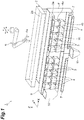
FIG. 1 is a perspective view illustrating a combinatorial weighing device according to an embodiment. -
FIG. 2 is a block diagram showing a configuration of the combinatorial weighing device inFIG. 1 . -
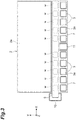
FIG. 3 is a plan view illustrating the combinatorial weighing device inFIG. 1 . -
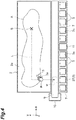
FIG. 4 is a plan view for describing stand-by insertion control of the combinatorial weighing device inFIG. 1 . -
FIG. 5(a) is a view for describing stand-by insertion control of the combinatorial weighing device inFIG. 1 .FIG. 5(b) is a view illustrating a continuation ofFIG. 5(a). FIG. 5(c) is a view illustrating a continuation ofFIG. 5(b). FIG. 5(d) is a view illustrating a continuation ofFIG. 5(c) . -
FIG. 6(a) is a view for describing direct insertion control of the combinatorial weighing device inFIG. 1 .FIG. 6(b) is a view illustrating a continuation ofFIG. 6(a) . - Hereinafter, an embodiment will be described in detail with reference to the drawings. In the following description, the same reference signs are applied to elements which are the same or corresponding, and duplicate description thereof will be omitted.
- As illustrated in any of
FIGS. 1 to 3 , acombinatorial weighing device 1 weighs articles (articles having uneven unit masses, such as agricultural products, aquatic products, and processed foods) supplied from the outside to achieve a target mass value and supplies the articles to a device such as a bag forming/packaging machine of a following stage, for example. Thecombinatorial weighing device 1 includes aretention unit 2, a plurality ofpool hoppers 3, a plurality of weighinghoppers 4, a weighing unit 5, arobot hand 6, supplyingconveyors 7, acontrol unit 8, acollection conveyor 9, and acollection box 10. In the following description, description will be given while a vertical direction is referred to as a Z direction, a horizontal direction corresponding to a forward-rearward direction of thecombinatorial weighing device 1 is referred to as a Y direction, and a horizontal direction perpendicular to the Y direction and the Z direction is referred to as an X direction. - The
retention unit 2 is a part for retaining articles (insertion targets) to be inserted into thepool hoppers 3. Theretention unit 2 exhibits a rectangular box shape opening upward while having the X direction as its longitudinal direction. Theretention unit 2 has aflat placement surface 2a. In theretention unit 2, an article supplied from the outside is placed on theplacement surface 2a and is retained therein. - The
pool hopper 3 is a container into which an article is inserted by therobot hand 6. Thepool hopper 3 exhibits a cup shape opening upward. Thepool hoppers 3 are supported directly or indirectly by a frame F. Thepool hoppers 3 are arranged side by side in the X direction at positions below theretention unit 2 and away from theretention unit 2 in the Y direction. An upper edge of thepool hopper 3 constitutes anarticle insertion port 3a through which an article is inserted. Thearticle insertion port 3a has a rectangular shape when viewed from above (refer toFIG. 3 ). Agate 3b which can be opened and closed is provided in a bottom portion of thepool hopper 3. Thepool hopper 3 receives an inserted article and temporarily retains the article by closing thegate 3b. Thepool hopper 3 discharges a temporarily retained article downward by opening thegate 3b. Opening/closing operation of thepool hopper 3 is controlled by thecontrol unit 8. - The weighing
hopper 4 is a container into which an article is inserted from thepool hopper 3. Similar to thepool hopper 3, the weighinghopper 4 exhibits a cup shape opening upward. The weighinghoppers 4 are supported directly or indirectly by the frame F.The weighing hoppers 4 are arranged side by side in the X direction below the plurality ofpool hoppers 3. The weighinghoppers 4 are disposed immediately below therespective gates 3b of the plurality ofpool hoppers 3. An upper edge of the weighinghopper 4 constitutes anarticle insertion port 4a through which an article is inserted. Thearticle insertion port 4a has a rectangular shape when viewed from above. Agate 4b which can be opened and closed is provided in a bottom portion of the weighinghopper 4. The weighinghopper 4 receives an article discharged from thepool hopper 3 immediately thereabove and temporarily retains the article by closing thegate 4b. The weighinghopper 4 discharges a temporarily retained article downward by opening thegate 4b. Opening/closing operation of the weighinghopper 4 is controlled by thecontrol unit 8. The expression "immediately below" denotes a place immediately below in the vertical direction, and the expression "immediately above" denotes a place immediately above in the vertical direction. - The weighing unit 5 weighs each of a plurality of articles retained in the plurality of
pool hoppers 3. Here, the weighing unit 5 weighs an article retained in thepool hopper 3 in the weighinghopper 4 immediately below thepool hopper 3. That is, the weighing unit 5 acquires a weighing value of an article retained in thepool hopper 3 immediately above the weighinghopper 4 by weighing the article temporarily retained inside the weighinghopper 4. The weighing unit 5 is disposed inside the frame F. The weighing unit 5 hasload cells 5a. A plurality ofload cells 5a corresponding to the number of weighinghoppers 4 are provided. Theload cells 5a support the corresponding weighinghoppers 4. When an article is temporarily retained in the weighinghopper 4, theload cell 5a outputs a weighing value corresponding to the mass of the article to thecontrol unit 8. - The
robot hand 6 inserts an article retained in theretention unit 2 into thepool hopper 3. Therobot hand 6 is a mechanical hand realizing work of grasping, releasing, carrying, and the like. Therobot hand 6 is constituted of a part (tip portion of a manipulator) of a robot apparatus. Therobot hand 6 has a holdingportion 6a for holding an article retained in theretention unit 2. Here, the holdingportion 6a is a gripping portion for gripping an article. Operation of therobot hand 6 is controlled by thecontrol unit 8. The kind, the specification, the function, the size, and the like of therobot hand 6 are not particularly limited. Various known robot hands can be used as therobot hand 6. - The supplying
conveyors 7 extend in the X direction below the plurality of weighinghoppers 4. The supplyingconveyors 7 are disposed separately on one side and the other side in the X direction. The supplyingconveyors 7 receive articles discharged from the weighinghoppers 4 and convey the articles toward achute 11. Conveyance operation of the supplyingconveyors 7 is controlled by thecontrol unit 8. Thechute 11 is disposed between one side and the other side of the supplyingconveyors 7. For example, thechute 11 is a rectangular tube body tapered downward. Thechute 11 receives articles conveyed by the supplyingconveyors 7 and discharges the articles downward. For example, articles discharged from thechute 11 are supplied to a device of a following stage. - The
control unit 8 is a computation device having a central processing unit (CPU), a read only memory (ROM), a random access memory (RAM), and the like. For example, thecontrol unit 8 is disposed inside the frame F. Thecontrol unit 8 controls operation of each unit in the combinatorial weighingdevice 1. - The
control unit 8 executes next combinatorial weighing processing. That is, thecontrol unit 8 stores weighing values which are weighed by the weighing unit 5 and are associated with the weighinghoppers 4 retaining articles corresponding to the weighing values. A combination of weighing values is selected from a plurality of weighing values weighed by the weighing unit 5 and associated with the respective weighinghoppers 4 such that a total value becomes a target mass value. More specifically, a combination of weighing values is selected from a plurality of weighing values output by the weighing unit 5 such that the total value settles within a predetermined range having the target mass value as a lower limit value. An open signal is output to the weighinghopper 4 related to the combination, thegate 4b thereof is set to an open state, and an article related to the combination is discharged to the supplyingconveyors 7. - The
control unit 8 outputs a close signal to the weighinghopper 4 which has completed discharging of an article, and thegate 4b thereof is set to a closed state. Thereafter, when it can be recognized that an article is retained in thepool hopper 3 immediately above the weighinghopper 4, thecontrol unit 8 outputs an open signal to thepool hopper 3, sets thegate 3b thereof to an open state, and causes the article to be discharged from thepool hopper 3 to the weighinghopper 4. Recognizing an article retained in the pool hopper 3 (that is, distinguishing whether thepool hopper 3 is empty or not) can be realized by a known technique and a known configuration. For example, an article inside thepool hopper 3 can be recognized on the basis of a detection result of a sensor such as a camera, an output history of an open signal or a close signal of thegate 3b, an operation history of therobot hand 6, or the like. - The
control unit 8 controls operation of therobot hand 6. Specifically, thecontrol unit 8 controls a holding operation of the holdingportion 6a of therobot hand 6 and a movement operation of the holdingportion 6a. Thecontrol unit 8 executes holding control in which an article retained in theretention unit 2 is held by the holdingportion 6a. For example, in holding control, an article retained in theretention unit 2 is detected by a camera, an infrared sensor, or the like mounted in therobot hand 6, and a position where the holdingportion 6a starts holding an article (which will hereinafter be referred to as "a holding start position") is obtained on the basis of a detection result thereof. Further, the holdingportion 6a is moved to the obtained holding start position, and the holdingportion 6a is caused to hold the article. - As illustrated in
FIGS. 3 and4 , thecontrol unit 8 causes the holdingportion 6a to hold an article B through holding control and then (in the present embodiment, immediately after) determines whether or not the article B can be inserted into apool hopper 3T (insertion target). For example, when no retained article B is recognized in thepool hopper 3T (when it is empty), thecontrol unit 8 determines that the article B can be inserted, and when the article B is recognized therein, thecontrol unit 8 determines that the article B cannot be inserted. Recognizing the article B retained in thepool hopper 3T can be realized by a known technique and a known configuration as described above. - The
control unit 8 executes stand-by insertion control when it is determined that the article B cannot be inserted into thepool hopper 3T serving as an insertion target. On the other hand, thecontrol unit 8 executes direct insertion control when it is determined that the article B can be inserted into thepool hopper 3T serving as an insertion target. - In stand-by insertion control, after the holding
portion 6a is temporarily disposed at a stand-by position W in a state in which the article B is held by the holdingportion 6a through holding control, the article B is inserted into thepool hopper 3 via thearticle insertion port 3a. Disposing the holdingportion 6a at the stand-by position W includes positioning a part (a central part or the like) of the holdingportion 6a at the stand-by position W and positioning a holding position of the holdingportion 6a at the stand-by position W. - The stand-by position W is set at a position different from a position immediately above the
article insertion port 3a in thepool hopper 3T serving as an insertion target. A position different from the position immediately above thearticle insertion port 3a is a position which is shifted from thearticle insertion port 3a and does not overlap thearticle insertion port 3a when viewed from above. The stand-by position W is set on a movement path from a holding start position S to the position immediately above thearticle insertion port 3a. The movement path is a path where the holdingportion 6a passes when the holdingportion 6a holding the article B is moved from the holding start position S to the position immediately above thearticle insertion port 3a. The movement path includes a movement trajectory, which will be described below. The stand-by position W is set at a position closer to thearticle insertion port 3a than the holding start position S. A position closer to thearticle insertion port 3a than the holding start position S is a position of the holdingportion 6a when the holdingportion 6a holding the article B at the holding start position S approaches thearticle insertion port 3a. - The stand-by position W is set in a region adjacent to the
article insertion port 3a of thepool hopper 3T serving as an insertion target in the Y direction when viewed from above. Here, stand-by positions W adjacent to each other in the Y direction are set for the respectivearticle insertion ports 3a of the plurality ofpool hoppers 3. The stand-by position W is set at a height position higher than thearticle insertion port 3a of thepool hopper 3. The stand-by position W is set to a place other than above theretention unit 2 when viewed from above. The stand-by position W is set between theretention unit 2 and thearticle insertion port 3a. The movement path and the stand-by position W may be set in advance and stored in thecontrol unit 8 or may be set through computation based on a positional relationship between the holding start position S and thepool hopper 3T serving as an insertion target every time stand-by insertion control is executed. - For example, in stand-by insertion control, the holding
portion 6a holding the article B is moved from the holding start position S to the stand-by position W. At this time, the holdingportion 6a is moved along a trajectory L above the retention unit which is a movement trajectory passing above theretention unit 2 if possible. For example, the trajectory L above the retention unit is a movement trajectory in which the holdingportion 6a moves upward from the holding start position S to a position (height position) of the stand-by position W in the Z direction, moves from the holding start position S in the X direction to a position of thepool hopper 3T in the X direction, and then moves to the stand-by position W in the Y direction. Subsequently, the holdingportion 6a is stopped at the stand-by position W for a certain time. A certain time may be a time set in advance or a time taken until thepool hopper 3T becomes empty. Subsequently, the holdingportion 6a is moved to a place immediately above thearticle insertion port 3a of thepool hopper 3T and is stopped thereat. Further, the article B held by the holdingportion 6a is released, and the article B is caused to freely fall and is inserted into thepool hopper 3T via thearticle insertion port 3a. InFIG. 4 , a range in which the article B is present is indicated by the reference sign A. - In direct insertion control, the holding
portion 6a is instantly moved to the position immediately above thearticle insertion port 3a without causing the holdingportion 6a to be temporarily disposed at the stand-by position W, and the article B is inserted into thepool hopper 3T via thearticle insertion port 3a. For example, in direct insertion control, the holdingportion 6a holding the article B is moved along the trajectory L above the retention unit to a place immediately above thepool hopper 3T serving as an insertion target as it stands without stopping at the stand-by position W and then is stopped thereat. Further, the article B held by the holdingportion 6a is released, and the article B is caused to freely fall and is inserted into thepool hopper 3T via thearticle insertion port 3a. - As illustrated in
FIGS. 1 and2 , thecollection conveyor 9 is disposed below the stand-by position W. Thecollection conveyor 9 extends in the X direction between theretention unit 2 and thearticle insertion port 3a such that a plurality of stand-by positions W are included when viewed from above. Thecollection conveyor 9 receives some or all of the articles B which have fallen from the holdingportion 6a during stand-by at the stand-by position W and conveys the received articles B in the X direction. Thecollection conveyor 9 constitutes a collection portion. - The
collection box 10 is disposed to be adjacent to a downstream side of thecollection conveyor 9 in a conveyance direction. Thecollection box 10 receives and stores the article B which has been conveyed by thecollection conveyor 9 and is discharged from a downstream end of thecollection conveyor 9. Hereinabove, in the present embodiment, theretention unit 2, therobot hand 6, thecontrol unit 8, thecollection conveyor 9, and the collection box constitute anarticle supplying apparatus 20. - Next, an example of control executed by the
control unit 8 when the article B is inserted using therobot hand 6 will be described usingFIGS. 5 and6 . - For example, when the
gate 4b of the weighinghopper 4 is opened, holding control is executed upon the fact (an output of an open signal from thecontrol unit 8 to the weighing hopper 4) as a trigger, and the article B retained in theretention unit 2 is held by the holdingportion 6a at the holding start position S. In parallel with this, thepool hopper 3 immediately above the weighinghopper 4 having the openedgate 4b is set as thepool hopper 3T serving as an insertion target. - Immediately after holding control is executed, it is determined whether or not the article B can be inserted into the
pool hopper 3T. As illustrated inFIG. 5(a) , when the article B is already retained in thepool hopper 3T, it is determined that an article cannot be inserted into thepool hopper 3T, and stand-by insertion control is executed. In stand-by insertion control, as illustrated inFIG. 5(b) , the holdingportion 6a holding the article B is temporarily disposed at the stand-by position W before being disposed at a position immediately above the article insertion port a. Accordingly, the article B held by the holdingportion 6a is temporarily disposed at the stand-by position W. As illustrated inFIG. 5(c) , while the holdingportion 6a is disposed at the stand-by position W, the article B is discharged from thepool hopper 3T to the weighinghopper 4. Thereafter, as illustrated inFIG. 5(d) , the holdingportion 6a is moved to a place immediately above thearticle insertion port 3a of thepool hopper 3T, the article B held by the holdingportion 6a is released, and the article B is inserted into thepool hopper 3T. - On the other hand, as illustrated in
FIG. 6(a) , when thepool hopper 3T is empty, it is determined that an article can be inserted into thepool hopper 3T, and direct insertion control is executed. In direct insertion control, as illustrated inFIG. 6(b) , the holdingportion 6a holding the article B is instantly moved to the position immediately above thearticle insertion port 3a, the article B held by the holdingportion 6a is released, and the article B is inserted into thepool hopper 3T. - Hereinabove, in the combinatorial weighing
device 1 and thearticle supplying apparatus 20 according to the present embodiment, during article insertion in which the article B is inserted into thepool hopper 3 by therobot hand 6, the holdingportion 6a is temporarily disposed at the stand-by position W in a state in which the article B is held by the holdingportion 6a of therobot hand 6. Thereafter, the holdingportion 6a is moved to the position immediately above thearticle insertion port 3a, and the article B is inserted into thepool hopper 3 from thearticle insertion port 3a. - Here, for example, depending on the kind or the like of the article B to be handled, even though the article B is held by the holding
portion 6a, there is a possibility that the article B may slip out of the holdingportion 6a with the lapse of time. In this regard, since the stand-by position W is different from the position immediately thereabove, even if some articles B slip out of the holdingportion 6a, erroneous insertion of some of the articles B which have slipped out into thepool hopper 3 can be curbed. In addition, even if the article B is a long article, contact of the article B with thepool hopper 3 at an unintended timing can be curbed. Moreover, the stand-by position W is a position set on the movement path from the holding start position S to the position immediately above thearticle insertion port 3a. Thus, for example, compared to when the holdingportion 6a stands by at a position away from the movement path, a time lag (delay) caused by operation of therobot hand 6 can be curbed, for example, and efficient article insertion can be maintained. - Therefore, in the combinatorial weighing
device 1 and thearticle supplying apparatus 20 utilizing therobot hand 6, efficient article insertion can be maintained and the article insertion can be appropriately performed. As a result, when the article B is weighed by the weighing unit 5, weighing abnormality and erroneous weighing caused by drop or the like from the holdingportion 6a can be prevented. - In the combinatorial weighing
device 1 and thearticle supplying apparatus 20, after the article B is held through holding control, it is determined whether or not the article B can be inserted into thepool hopper 3T serving as an insertion target. Stand-by insertion control is executed when it is determined that the article B cannot be inserted, and direct insertion control is executed when it is determined that the article B can be inserted. In this configuration, during article insertion performed by therobot hand 6, the holdingportion 6a is not temporarily disposed at the stand-by position W at all times, but an article is inserted into thepool hopper 3T as it stands without causing the holding portion to be temporarily disposed at the stand-by position W when the article B can be inserted. Thus, unnecessary stand-by of the holdingportion 6a can be curbed, and efficient article insertion can be realized. - In the combinatorial weighing
device 1 and thearticle supplying apparatus 20, the stand-by position W is a position closer to thearticle insertion port 3a than the holding start position S. Thus, for example, compared to when the holdingportion 6a stands by at the holding start position S or a position away from thearticle insertion port 3a than the holding start position S, the time lag described above can be curbed, and efficient article insertion can be maintained. - In the combinatorial weighing
device 1 and thearticle supplying apparatus 20, the stand-by position W is set in a region adjacent to thearticle insertion port 3a when viewed from above. In this configuration, the time lag described above can be further curbed, and efficient article insertion can be realized. - In the combinatorial weighing
device 1 and thearticle supplying apparatus 20, thecollection conveyor 9 receiving the article B which has fallen from the holdingportion 6a is disposed below the stand-by position W. In this configuration, the article B which has slipped out of the holdingportion 6a during stand-by at the stand-by position W can be collected by thecollection conveyor 9. The article B which has been collected by thecollection conveyor 9 and stored in thecollection box 10 can be returned to theretention unit 2 through automatic or manual work. For example, when the collected article B is automatically returned to theretention unit 2, a circulation conveyor conveying the article B from thecollection box 10 to theretention unit 2 may be provided. - In the combinatorial weighing
device 1 and thearticle supplying apparatus 20, the stand-by position W may be set at a height position higher than thearticle insertion port 3a and between theretention unit 2 and thearticle insertion port 3a when viewed from above. In this configuration, the time lag described above can be further curbed, and efficient article insertion can be realized. - Hereinabove, an embodiment has been described. However, the present invention is not limited to the foregoing embodiment.
- In the foregoing embodiment, an example in which holding control is started upon opening of the
gate 4b of the weighinghopper 4 as a trigger and the article B is inserted while having thepool hopper 3 immediately above the weighinghopper 4 as an insertion target has been described, but the embodiment is not limited thereto. For example, holding control may be started (that is, article insertion may be executed successively) upon completion of stand-by insertion control or direct insertion control as a trigger. Alternatively, holding control may be started upon the elapse of certain time after completion of stand-by insertion control or direct insertion control as a trigger. In addition, for example, the article B may be inserted while having any arbitrary one of a plurality ofpool hoppers 3 as an insertion target. Alternatively, apool hopper 3 closer to the holding start position S may be taken as an insertion target. Alternatively, any one which has been randomly selected from the plurality ofpool hoppers 3 may be taken as an insertion target. Alternatively, when anempty pool hopper 3 is present, theempty pool hopper 3 may be preferentially taken as an insertion target. - The foregoing embodiment may further include a sensor for detecting that the article B held by the holding
portion 6a is away from theplacement surface 2a of the retention unit 2 (does not come into contact with theplacement surface 2a). This configuration is particularly effective in confirming that the article B is isolated from theplacement surface 2a when the article B is a long article, for example. - In the foregoing embodiment, the number of
robot hands 6 is not limited, and a plurality ofrobot hands 6 may be provided. In the foregoing embodiment, the article B is inserted into thepool hopper 3 by therobot hand 6. However, for example, when the combinatorial weighingdevice 1 has nopool hoppers 3, the article B may be inserted into the weighinghopper 4 by therobot hand 6. In the foregoing embodiment, the holdingportion 6a is moved along the trajectory L above the retention unit, but a trajectory along which the holdingportion 6a is moved is not particularly limited. As long as the holdingportion 6a can be moved to the stand-by position W or the position immediately above thearticle insertion port 3a, the holdingportion 6a may be moved along every possible trajectory. - In the foregoing embodiment, a weighing function may be mounted in the
robot hand 6. That is, in place of or in addition to the weighing unit 5, a weighing unit weighing the article B being held by the holdingportion 6a of therobot hand 6 may be included. The foregoing embodiment has a configuration in which the holdingportion 6a grips the article B, but the configuration of the holdingportion 6a is not particularly limited. The holdingportion 6a may have a configuration in which the article B is scooped in place of or in addition to a configuration of gripping the article B, may have a configuration of adsorbing the article B, may have a configuration of supporting the article B from below, or may have a configuration in which these are combined. - In the foregoing embodiment, the stand-by position W is not particularly limited and need only be different from the position immediately above the
article insertion port 3a and set at a position closer to thearticle insertion port 3a than the holding start position S. In the foregoing embodiment, the same number of stand-by positions W as the number ofpool hoppers 3 is set, but one stand-by position W may be set for a plurality ofpool hoppers 3 or a plurality of stand-by positions W may be set for onepool hopper 3. - In the foregoing embodiment, the
retention unit 2 is not limited to an element having theplacement surface 2a and may have an arbitrary shape. For example, theretention unit 2 may have a configuration in which an article is deposited inside an accommodation container. In the foregoing embodiment, theplacement surface 2a of theretention unit 2 may be inclined with respect to a horizontal surface such that no article B remains in theretention unit 2. In the foregoing embodiment, theretention unit 2 may be oscillated such that no article B remains in theretention unit 2. - In the foregoing embodiment, the
collection conveyor 9 is disposed below the stand-by position W to serve as a collection portion, but a collection portion is not limited to thecollection conveyor 9. For example, when the stand-by position W is set above theretention unit 2, the article B which has fallen from the holdingportion 6a can be received by theretention unit 2. Therefore, in this case, theretention unit 2 constitutes a collection portion. - In the foregoing embodiment, it is determined whether or not the article B can be inserted into the
pool hopper 3T serving as an insertion target immediately after the article B is held by the holdingportion 6a, but the determination is not limited to being executed immediately after the article B is held and need only be executed after the article B is held. For example, in thearticle supplying apparatus 20 including a plurality ofrobot hands 6, when the article B is held by acertain robot hand 6, determining whether or not the article B can be inserted into thepool hopper 3T may be executed at an arbitrary timing while anotherrobot hand 6 is holding, moving, or inserting the article B. - In the foregoing embodiment, the
article supplying apparatus 20 is applied to the combinatorial weighingdevice 1 but may be applied to various other combinatorial weighing devices or may also be applied to devices other than combinatorial weighing devices. The foregoing embodiment can also be regarded as an embodiment for an article supplying method or a combinatorial weighing method. -
- 1
- Combinatorial weighing device
- 2
- Retention unit
- 3
- Pool hopper (hopper, container)
- 3a
- Article insertion port
- 5
- Weighing unit
- 6
- Robot hand
- 6a
- Holding portion
- 8
- Control unit
- 9
- Collection conveyor (collection portion)
- 20
- Article supplying apparatus
- B
- Article
- S
- Holding start position (start position of holding)
- W
- Stand-by position
Claims (7)
- An article supplying apparatus comprising:a retention unit configured to retain an article serving as an insertion target;a robot hand configured to insert the article retained in the retention unit into a container; anda control unit configured to control operation of the robot hand,whereinthe robot hand has a holding portion for holding the article, andthe control unit is configured to executeholding control in which the article retained in the retention unit is held by the holding portion, andstand-by insertion control in which, after the holding portion is temporarily disposed at a stand-by position different from a position immediately above an article insertion port in the container and set on a movement path from a start position of the holding through the holding control to the position immediately thereabove in a state in which the article is held by the holding portion, the holding portion is moved to the position immediately thereabove, and the article is inserted into the container via the article insertion port.
- The article supplying apparatus according to claim 1,
wherein the control unit is configured to:cause the holding portion to hold the article through the holding control and then determine whether or not the article is able to be inserted into the container,execute the stand-by insertion control when it is determined that the article is not able to be inserted into the container, andexecute direct insertion control in which the holding portion is instantly moved to the position immediately thereabove without being temporarily disposed at the stand-by position and the article is inserted into the container via the article insertion port when it is determined that the article is able to be inserted into the container. - The article supplying apparatus according to claim 1 or 2,
wherein the stand-by position is set at a position closer to the article insertion port than the start position of the holding through the holding control. - The article supplying apparatus according to any one of claims 1 to 3,
wherein the stand-by position is set in a region adjacent to the article insertion port when viewed from above. - The article supplying apparatus according to any one of claims 1 to 4,
wherein a collection portion receiving the article which has fallen from the holding portion is disposed below the stand-by position. - The article supplying apparatus according to any one of claims 1 to 5,
wherein the stand-by position is set at a height position higher than the article insertion port and between the retention unit and the article insertion port when viewed from above. - A combinatorial weighing device comprising:a retention unit configured to retain an article serving as an insertion target;a plurality of hoppers configured to allow the article to be inserted thereinto and to temporarily retain the article;a weighing unit configured to weigh each of a plurality of the articles retained in the plurality of hoppers;a robot hand configured to insert the article retained in the retention unit into the hopper; anda control unit configured to control operation of the robot hand, to select a plurality of the articles, of which a sum of weighing values becomes a target mass value set in advance, from the plurality of the articles weighed by the weighing unit, and to discharge the plurality of the selected articles from the hoppers,whereinthe robot hand has a holding portion for holding the article, andthe control unit is configured to executeholding control in which the article retained in the retention unit is held by the holding portion, andstand-by insertion control in which after the holding portion is temporarily disposed at a stand-by position different from a position immediately above an article insertion port in the hopper and set at a position closer to the article insertion port than a start position of holding through the holding control in a state in which the article is held by the holding portion through the holding control, the article is inserted into the hopper via the article insertion port.
Applications Claiming Priority (2)
| Application Number | Priority Date | Filing Date | Title |
|---|---|---|---|
| JP2017214769A JP6921411B2 (en) | 2017-11-07 | 2017-11-07 | Goods supply device and combination weighing device |
| PCT/JP2018/032906 WO2019092964A1 (en) | 2017-11-07 | 2018-09-05 | Article supplying apparatus and combinatorial weighing device |
Publications (2)
| Publication Number | Publication Date |
|---|---|
| EP3708979A1 true EP3708979A1 (en) | 2020-09-16 |
| EP3708979A4 EP3708979A4 (en) | 2021-11-17 |
Family
ID=66437767
Family Applications (1)
| Application Number | Title | Priority Date | Filing Date |
|---|---|---|---|
| EP18876143.1A Withdrawn EP3708979A4 (en) | 2017-11-07 | 2018-09-05 | Article supplying apparatus and combinatorial weighing device |
Country Status (5)
| Country | Link |
|---|---|
| US (1) | US11613435B2 (en) |
| EP (1) | EP3708979A4 (en) |
| JP (1) | JP6921411B2 (en) |
| CN (1) | CN111279163B (en) |
| WO (1) | WO2019092964A1 (en) |
Families Citing this family (6)
| Publication number | Priority date | Publication date | Assignee | Title |
|---|---|---|---|---|
| US20220234078A1 (en) * | 2018-11-14 | 2022-07-28 | Michael Anthony Bartrom | Automated Feeding, Sorting, and Packaging System for a Farm with Robots Working on Plants |
| US11534802B2 (en) * | 2019-05-09 | 2022-12-27 | Steven Theodore Chandler | Automated method and system for sorting and combining varying density payloads |
| JP7491543B2 (en) * | 2019-09-26 | 2024-05-28 | 株式会社イシダ | Weighing Device |
| JP7701040B2 (en) * | 2021-10-05 | 2025-07-01 | 株式会社イシダ | Combination Weighing Device |
| JP2023178912A (en) * | 2022-06-06 | 2023-12-18 | 株式会社アールティ | Robot and goods pickup system |
| JP2023178914A (en) * | 2022-06-06 | 2023-12-18 | 大和製衡株式会社 | Weighing device and article pickup system |
Family Cites Families (23)
| Publication number | Priority date | Publication date | Assignee | Title |
|---|---|---|---|---|
| US5699655A (en) | 1994-12-05 | 1997-12-23 | Fuji Electric Co., Ltd. | Food material transferring apparatus |
| JPH08154841A (en) * | 1994-12-05 | 1996-06-18 | Fuji Electric Co Ltd | Food delivery device |
| IT1285576B1 (en) * | 1996-03-01 | 1998-06-18 | Gd Spa | CONVEYOR GROUP OF PRODUCTS |
| JP2000058625A (en) * | 1998-06-02 | 2000-02-25 | Mecs Corp | Substrate transfer device |
| JP2001050803A (en) * | 1999-08-06 | 2001-02-23 | Ishida Co Ltd | Combination weighing device |
| JP2002052487A (en) * | 2000-08-10 | 2002-02-19 | Jt Engineering Inc | Fruit/vegetable retainer and transfer device |
| JP4880321B2 (en) * | 2005-12-13 | 2012-02-22 | 勝三 川西 | Combination weigher and weighing device using the same |
| EP2018528B1 (en) * | 2006-05-19 | 2015-10-21 | Marel A/S | A method and a system for batching of objects |
| DE102006041829A1 (en) * | 2006-09-06 | 2008-03-27 | Poly-Clip System Gmbh & Co Kg | Production line for the production of sausage-shaped products |
| US7952036B2 (en) * | 2008-10-30 | 2011-05-31 | Yamato Corporation | Combinational weigher with a recycle conveyor configured to allow products to be recirculated in a dispersed manner |
| JP4424691B1 (en) * | 2009-10-05 | 2010-03-03 | ピービーエム株式会社 | Automatic collation bookbinding system |
| JP2012052487A (en) | 2010-09-02 | 2012-03-15 | Toyota Motor Corp | Engine exhaust device |
| EP2745999A1 (en) | 2011-08-19 | 2014-06-25 | Kabushiki Kaisha Yaskawa Denki | Robot system, robot control device, robot hand and method for controlling robot |
| CN202606414U (en) * | 2012-01-19 | 2012-12-19 | 潍坊市志永机电科技有限公司 | Separation scale |
| JP2015219190A (en) | 2014-05-20 | 2015-12-07 | 株式会社イシダ | Combination weighing method and combination weighing device |
| JP6444743B2 (en) * | 2015-01-20 | 2018-12-26 | ナビック株式会社 | Automatic feeder |
| US10036664B2 (en) * | 2015-04-03 | 2018-07-31 | Bot Llc | Method and apparatus for sorting and combining fragile and varying density pieces |
| KR101776851B1 (en) * | 2015-06-04 | 2017-09-11 | 여계성 | An Apparatus for Inspecting Unit Weight Automatically |
| CN105083926B (en) * | 2015-09-02 | 2017-06-23 | 浙江腾云制冷科技有限公司 | A kind of feed mechanism |
| CN205361555U (en) * | 2016-01-21 | 2016-07-06 | 汕头市信一塑机制造有限公司 | Pulverizer |
| CN206423466U (en) * | 2016-07-04 | 2017-08-22 | 江油市丹阳机电设备有限责任公司 | The automatic dispenser of particulate species material |
| JP6845559B2 (en) * | 2016-11-30 | 2021-03-17 | 株式会社イシダ | Goods transfer device |
| CN206479241U (en) * | 2017-01-24 | 2017-09-08 | 深圳市恒瑞兴自动化设备有限公司 | Weighing device |
-
2017
- 2017-11-07 JP JP2017214769A patent/JP6921411B2/en active Active
-
2018
- 2018-09-05 WO PCT/JP2018/032906 patent/WO2019092964A1/en not_active Ceased
- 2018-09-05 US US16/761,232 patent/US11613435B2/en active Active
- 2018-09-05 EP EP18876143.1A patent/EP3708979A4/en not_active Withdrawn
- 2018-09-05 CN CN201880070070.0A patent/CN111279163B/en active Active
Also Published As
| Publication number | Publication date |
|---|---|
| US20200354168A1 (en) | 2020-11-12 |
| WO2019092964A1 (en) | 2019-05-16 |
| JP2019086398A (en) | 2019-06-06 |
| US11613435B2 (en) | 2023-03-28 |
| EP3708979A4 (en) | 2021-11-17 |
| CN111279163B (en) | 2022-03-29 |
| JP6921411B2 (en) | 2021-08-18 |
| CN111279163A (en) | 2020-06-12 |
Similar Documents
| Publication | Publication Date | Title |
|---|---|---|
| US11613435B2 (en) | Article supplying apparatus and combinatorial weighing device | |
| US11230395B2 (en) | Method and device for filling and closing pharmaceutical object | |
| EP1176405B1 (en) | Combination weighing apparatus having a supply unit | |
| US9896280B2 (en) | Stacked tilt tray and cross-belt sorting system | |
| EP3318498B1 (en) | Method and device for packaging groups of objects | |
| CN108290693A (en) | The conveyer chain of cargo transfer means for automatic cargo storage system | |
| CN111867790B (en) | Item moving and loading device | |
| EP3431937A1 (en) | Combination weighing device | |
| EP3517904B1 (en) | Hopper and combination weighing device | |
| EP3180170B1 (en) | Method and device for automatic packing of wood | |
| JP6582421B2 (en) | Article distribution input device | |
| CN102640172B (en) | For the equipment to the article counting supplied as loose unpacked material | |
| EP3431936B1 (en) | Combination weighing device | |
| EP3564632A1 (en) | Combination weighing device | |
| KR20170102466A (en) | Commissioning Device and Process for Outputting Piece Goods Using the Commissioning Device | |
| KR20180066408A (en) | System for controlling package weight of agricultural products sorting apparatus | |
| WO2018139221A1 (en) | Combination weighing device, combination weighing system, and area setting device | |
| CN110809555B (en) | Method and apparatus for managing a unit classification module | |
| CN109071048B (en) | Egg processing device and control device | |
| CN108349665B (en) | Cargo lifts for cargo transfer devices for automatic cargo storage systems | |
| JP6623096B2 (en) | Weight sorter | |
| US20240300753A1 (en) | Improved method for loading a target loading aid, and warehouse and picking system therefor | |
| JPH0659324U (en) | Goods supply equipment | |
| JPH09152371A (en) | Combination scale | |
| JP2020153747A (en) | Test piece ejector and combination weighing device |
Legal Events
| Date | Code | Title | Description |
|---|---|---|---|
| STAA | Information on the status of an ep patent application or granted ep patent |
Free format text: STATUS: THE INTERNATIONAL PUBLICATION HAS BEEN MADE |
|
| PUAI | Public reference made under article 153(3) epc to a published international application that has entered the european phase |
Free format text: ORIGINAL CODE: 0009012 |
|
| STAA | Information on the status of an ep patent application or granted ep patent |
Free format text: STATUS: REQUEST FOR EXAMINATION WAS MADE |
|
| 17P | Request for examination filed |
Effective date: 20200522 |
|
| AK | Designated contracting states |
Kind code of ref document: A1 Designated state(s): AL AT BE BG CH CY CZ DE DK EE ES FI FR GB GR HR HU IE IS IT LI LT LU LV MC MK MT NL NO PL PT RO RS SE SI SK SM TR |
|
| AX | Request for extension of the european patent |
Extension state: BA ME |
|
| DAV | Request for validation of the european patent (deleted) | ||
| DAX | Request for extension of the european patent (deleted) | ||
| RIC1 | Information provided on ipc code assigned before grant |
Ipc: G01G 19/387 20060101AFI20210706BHEP Ipc: B25J 13/00 20060101ALI20210706BHEP Ipc: B65G 65/32 20060101ALI20210706BHEP Ipc: G01G 19/393 20060101ALI20210706BHEP |
|
| A4 | Supplementary search report drawn up and despatched |
Effective date: 20211015 |
|
| RIC1 | Information provided on ipc code assigned before grant |
Ipc: G01G 19/393 20060101ALI20211011BHEP Ipc: B65G 65/32 20060101ALI20211011BHEP Ipc: B25J 13/00 20060101ALI20211011BHEP Ipc: G01G 19/387 20060101AFI20211011BHEP |
|
| REG | Reference to a national code |
Ref country code: DE Ref legal event code: R079 Free format text: PREVIOUS MAIN CLASS: G01G0019387000 Ipc: G01G0019393000 |
|
| GRAP | Despatch of communication of intention to grant a patent |
Free format text: ORIGINAL CODE: EPIDOSNIGR1 |
|
| STAA | Information on the status of an ep patent application or granted ep patent |
Free format text: STATUS: GRANT OF PATENT IS INTENDED |
|
| RIC1 | Information provided on ipc code assigned before grant |
Ipc: G01G 19/387 20060101ALN20230320BHEP Ipc: G05B 19/418 20060101ALI20230320BHEP Ipc: B25J 9/00 20060101ALI20230320BHEP Ipc: G01G 19/393 20060101AFI20230320BHEP |
|
| RIC1 | Information provided on ipc code assigned before grant |
Ipc: G01G 19/387 20060101ALN20230328BHEP Ipc: G05B 19/418 20060101ALI20230328BHEP Ipc: B25J 9/00 20060101ALI20230328BHEP Ipc: G01G 19/393 20060101AFI20230328BHEP |
|
| INTG | Intention to grant announced |
Effective date: 20230414 |
|
| STAA | Information on the status of an ep patent application or granted ep patent |
Free format text: STATUS: THE APPLICATION IS DEEMED TO BE WITHDRAWN |
|
| 18D | Application deemed to be withdrawn |
Effective date: 20230825 |