EP3708957A1 - Vehicle-mounted device, recording medium, and notification method - Google Patents
Vehicle-mounted device, recording medium, and notification method Download PDFInfo
- Publication number
- EP3708957A1 EP3708957A1 EP18876443.5A EP18876443A EP3708957A1 EP 3708957 A1 EP3708957 A1 EP 3708957A1 EP 18876443 A EP18876443 A EP 18876443A EP 3708957 A1 EP3708957 A1 EP 3708957A1
- Authority
- EP
- European Patent Office
- Prior art keywords
- vehicle
- notification
- mobile terminal
- mounted device
- mobile
- Prior art date
- Legal status (The legal status is an assumption and is not a legal conclusion. Google has not performed a legal analysis and makes no representation as to the accuracy of the status listed.)
- Withdrawn
Links
Images


Classifications
-
- G—PHYSICS
- G08—SIGNALLING
- G08G—TRAFFIC CONTROL SYSTEMS
- G08G1/00—Traffic control systems for road vehicles
- G08G1/09—Arrangements for giving variable traffic instructions
- G08G1/0962—Arrangements for giving variable traffic instructions having an indicator mounted inside the vehicle, e.g. giving voice messages
- G08G1/0968—Systems involving transmission of navigation instructions to the vehicle
- G08G1/0969—Systems involving transmission of navigation instructions to the vehicle having a display in the form of a map
-
- G—PHYSICS
- G01—MEASURING; TESTING
- G01C—MEASURING DISTANCES, LEVELS OR BEARINGS; SURVEYING; NAVIGATION; GYROSCOPIC INSTRUMENTS; PHOTOGRAMMETRY OR VIDEOGRAMMETRY
- G01C21/00—Navigation; Navigational instruments not provided for in groups G01C1/00 - G01C19/00
- G01C21/26—Navigation; Navigational instruments not provided for in groups G01C1/00 - G01C19/00 specially adapted for navigation in a road network
- G01C21/34—Route searching; Route guidance
- G01C21/36—Input/output arrangements for on-board computers
- G01C21/3688—Systems comprising multiple parts or multiple output devices (not client-server), e.g. detachable faceplates, key fobs or multiple output screens
-
- G—PHYSICS
- G01—MEASURING; TESTING
- G01C—MEASURING DISTANCES, LEVELS OR BEARINGS; SURVEYING; NAVIGATION; GYROSCOPIC INSTRUMENTS; PHOTOGRAMMETRY OR VIDEOGRAMMETRY
- G01C21/00—Navigation; Navigational instruments not provided for in groups G01C1/00 - G01C19/00
- G01C21/26—Navigation; Navigational instruments not provided for in groups G01C1/00 - G01C19/00 specially adapted for navigation in a road network
- G01C21/34—Route searching; Route guidance
- G01C21/3407—Route searching; Route guidance specially adapted for specific applications
- G01C21/3415—Dynamic re-routing, e.g. recalculating the route when the user deviates from calculated route or after detecting real-time traffic data or accidents
-
- G—PHYSICS
- G01—MEASURING; TESTING
- G01C—MEASURING DISTANCES, LEVELS OR BEARINGS; SURVEYING; NAVIGATION; GYROSCOPIC INSTRUMENTS; PHOTOGRAMMETRY OR VIDEOGRAMMETRY
- G01C21/00—Navigation; Navigational instruments not provided for in groups G01C1/00 - G01C19/00
- G01C21/26—Navigation; Navigational instruments not provided for in groups G01C1/00 - G01C19/00 specially adapted for navigation in a road network
- G01C21/34—Route searching; Route guidance
- G01C21/36—Input/output arrangements for on-board computers
- G01C21/3605—Destination input or retrieval
- G01C21/362—Destination input or retrieval received from an external device or application, e.g. PDA, mobile phone or calendar application
-
- G—PHYSICS
- G01—MEASURING; TESTING
- G01C—MEASURING DISTANCES, LEVELS OR BEARINGS; SURVEYING; NAVIGATION; GYROSCOPIC INSTRUMENTS; PHOTOGRAMMETRY OR VIDEOGRAMMETRY
- G01C21/00—Navigation; Navigational instruments not provided for in groups G01C1/00 - G01C19/00
- G01C21/26—Navigation; Navigational instruments not provided for in groups G01C1/00 - G01C19/00 specially adapted for navigation in a road network
- G01C21/34—Route searching; Route guidance
- G01C21/36—Input/output arrangements for on-board computers
- G01C21/3626—Details of the output of route guidance instructions
- G01C21/3655—Timing of guidance instructions
-
- G—PHYSICS
- G08—SIGNALLING
- G08G—TRAFFIC CONTROL SYSTEMS
- G08G1/00—Traffic control systems for road vehicles
- G08G1/005—Traffic control systems for road vehicles including pedestrian guidance indicator
-
- G—PHYSICS
- G09—EDUCATION; CRYPTOGRAPHY; DISPLAY; ADVERTISING; SEALS
- G09B—EDUCATIONAL OR DEMONSTRATION APPLIANCES; APPLIANCES FOR TEACHING, OR COMMUNICATING WITH, THE BLIND, DEAF OR MUTE; MODELS; PLANETARIA; GLOBES; MAPS; DIAGRAMS
- G09B29/00—Maps; Plans; Charts; Diagrams, e.g. route diagram
-
- G—PHYSICS
- G09—EDUCATION; CRYPTOGRAPHY; DISPLAY; ADVERTISING; SEALS
- G09B—EDUCATIONAL OR DEMONSTRATION APPLIANCES; APPLIANCES FOR TEACHING, OR COMMUNICATING WITH, THE BLIND, DEAF OR MUTE; MODELS; PLANETARIA; GLOBES; MAPS; DIAGRAMS
- G09B29/00—Maps; Plans; Charts; Diagrams, e.g. route diagram
- G09B29/10—Map spot or coordinate position indicators; Map reading aids
Definitions
- the present invention relates to a vehicle-mounted device, a recording medium, and a notification method.
- PTL 1 discloses a vehicle-mounted device that performs route guidance in conjunction with a mobile terminal, comprising: a route guidance unit that performs route guidance to a destination; a parking determination unit that determines whether a vehicle in which the vehicle-mounted device is installed is in a parked state; and a notification unit that, when a parked state is determined by the parking determination unit, notifies the mobile terminal of route guidance information which the vehicle-mounted device has.
- the invention disclosed in PTL 1 is unable to deal with cases where it is unclear that a vehicle has stopped.
- a vehicle-mounted device is a vehicle-mounted device installed in a vehicle, comprising: a communication unit that communicates with a mobile terminal; a vehicle information acquiring unit that acquires operation information of the vehicle; and a vehicle-mounted controller that, on the basis of an operating status of the vehicle-mounted device, transmits a first notification notifying the mobile terminal of the possibility that the vehicle has stopped to the mobile terminal via the communication unit and that, on the basis of the operation information of the vehicle, transmits a second notification notifying the mobile terminal that the vehicle has stopped to the mobile terminal via the communication unit.
- a recording medium is computer-readable and records a notification program for causing a vehicle-mounted device that communicates with a mobile terminal installed in a vehicle to execute the steps of: acquiring an operating status of the vehicle-mounted device; acquiring operation information of the vehicle; and transmitting, on the basis of the operating status of the vehicle-mounted device, a first notification notifying the mobile terminal of the possibility that the vehicle has stopped and transmitting, on the basis of the operation information of the vehicle, a second notification notifying the mobile terminal that the vehicle has stopped, to the mobile terminal.
- a notification method is a notification method which is executed in a vehicle-mounted device that is installed in a vehicle and that communicates with a mobile terminal, comprising the steps of: acquiring an operating status of the vehicle-mounted device; acquiring operation information of the vehicle; and transmitting, on the basis of the operating status of the vehicle-mounted device, a first notification notifying the mobile terminal of the possibility that the vehicle has stopped to the mobile terminal and transmitting, on the basis of the operation information of the vehicle, a second notification notifying the mobile terminal that the vehicle has stopped to the mobile terminal.
- the vehicle-mounted device is capable of notifying a mobile terminal of the possibility that a vehicle has stopped.
- a notification system S illustrated in Fig. 1 is provided with a vehicle-mounted device 1, a mobile terminal 2, and a server 3.
- the vehicle-mounted device 1 performs short range radio communication with the mobile terminal 2, and the mobile terminal 2 performs long range radio communication with the server 3.
- a user always carries the mobile terminal 2.
- the user rides in a vehicle (hereinafter "own vehicle") in which the vehicle-mounted device 1 is installed and moves to a parking lot close to a destination (hereinafter “destination parking lot”) and moves from the destination parking lot to the destination by walking.
- a vehicle navigation system is also called “vehicle navigation” and a walking navigation system is also called “walking navigation”.
- the vehicle-mounted device 1 is provided with a vehicle-mounted controller 11, a vehicle-mounted display unit 12, a vehicle-mounted input unit 13, a vehicle-mounted GPS receiver 14, a vehicle-mounted accelerometer 15, a gyro sensor 16, a vehicle speed acquiring unit 17, a vehicle-mounted short range communication unit 18, and a map database (hereinafter map DB) 19.
- map DB map database
- the vehicle-mounted controller 11 is provided with a CPU, a ROM, and a RAM, which are not illustrated.
- the CPU realizes functions (described subsequently) by expanding a program, which is stored in the ROM, in the RAM and executing the program.
- the vehicle-mounted controller 11 outputs operating instructions to the vehicle-mounted display unit 12 and the vehicle-mounted short range communication unit 18.
- the vehicle-mounted display unit 12 is, for example, a liquid crystal display, and displays video on the basis of operating instructions from the vehicle-mounted controller 11.
- the vehicle-mounted input unit 13 is, for example, buttons, and outputs operating inputs by the user to the vehicle-mounted controller 11.
- the vehicle-mounted input unit 13 also includes a power button for turning off the power supply of the vehicle-mounted device 1. Furthermore, when an ignition switch of the own vehicle is turned off by the user, this operation is relayed to the vehicle-mounted input unit 13 via a signal line (not illustrated), and the vehicle-mounted input unit 13 outputs the same signal as when the power button is pressed to the vehicle-mounted controller 11. Note that, upon receiving this signal, the vehicle-mounted controller 11 performs an end preparation to stop the operation of the vehicle-mounted device 1, and when this preparation is complete, the vehicle-mounted controller 11 stops the operation of the vehicle-mounted device 1, that is, disconnects the power supply.
- the vehicle-mounted GPS receiver 14 receives radio waves from a plurality of satellites constituting a satellite navigation system and calculates the position, that is, the latitude and longitude, of the own vehicle by analyzing the signals contained in the radio waves.
- the vehicle-mounted GPS receiver 14 outputs the calculated latitude and longitude to the vehicle-mounted controller 11.
- the vehicle-mounted accelerometer 15 is a triaxial accelerometer, for example, that measures the acceleration of the own vehicle and outputs same to the vehicle-mounted controller 11.
- the gyro sensor 16 measures the direction of travel of the own vehicle and outputs same to the vehicle-mounted controller 11.
- the vehicle speed acquiring unit 17 receives the output of a speedometer, which the own vehicle is provided with, via a signal line (not illustrated), and outputs vehicle speed information to the vehicle-mounted controller 11.
- the vehicle-mounted short range communication unit 18 is a communication device with a narrow communication range that is Bluetooth (registered trademark)-compatible or IEEE 802.11-compatible, for example.
- the vehicle-mounted short range communication unit 18 performs communication by radio with a mobile short range communication unit 28A that lies within a communicable range.
- the communicable range may include at least the own vehicle interior, or the vicinity of the own vehicle, such as a range of a few meters, for example, may be the communicable range.
- the vehicle-mounted short range communication unit 18 establishes communication with the mobile short range communication unit 28A by means of a predetermined procedure before sending and receiving data to and from the mobile short range communication unit 28A. In the present embodiment, the establishment of communication is also referred to as a "connection".
- the vehicle-mounted short range communication unit 18 When establishing communication with the mobile short range communication unit 28A, the vehicle-mounted short range communication unit 18 transmits a signal to confirm presence ("presence confirmation" hereinbelow) at regular intervals in order to confirm that the mobile short range communication unit 28A is in a communicable range. Because the mobile short range communication unit 28A sends back a predetermined response upon receiving the presence confirmation, if this response is not obtained, the vehicle-mounted short range communication unit 18 determines that the mobile short range communication unit 28A has moved out of the communicable range, that is, that the connection with the mobile terminal 2 has been broken.
- Presence confirmation hereinbelow
- the map DB 19 is a database in which road information and POI (Point Of Interest) information are stored. This POI also includes the home of the user, which the user has input beforehand.
- the vehicle-mounted controller 11 calculates a travel route from a current location to a destination parking lot by referring to the map DB 19. Note that, as will be described subsequently, this destination parking lot is relayed from the mobile terminal 2.
- the mobile terminal 2 is provided with a mobile controller 21, a mobile display unit 22, a loudspeaker 22A, a vibrator 22B, a mobile input unit 23, a mobile GPS receiver 24, a mobile accelerometer 25, a mobile short range communication unit 28A, a long range communication unit 28B, an event list table 29A, and a notification condition table 29B.
- the mobile controller 21 is provided with a CPU, a ROM, and a RAM, which are not illustrated.
- the CPU realizes functions (described subsequently) by expanding a program, which is stored in the ROM, in the RAM and executing the program.
- the mobile controller 21 outputs operating instructions to the mobile display unit 22, the loudspeaker 22A, the vibrator 22B, the mobile short range communication unit 28A, and the long range communication unit 28B.
- the mobile display unit 22 is, for example, a liquid crystal display, and displays video on the basis of operating instructions from the mobile controller 21.
- the loudspeaker 22A outputs speech on the basis of operating instructions from the mobile controller 21.
- the vibrator 22B reports to the user by vibrating on the basis of operating instructions from the mobile controller 21.
- the mobile input unit 23 is configured comprising a plurality of buttons, and relays user inputs to the mobile controller 21, for example. However, the mobile input unit 23 may also be configured as a touch panel which is integral to the mobile display unit 22.
- the mobile GPS receiver 24 receives radio waves from a plurality of satellites constituting a satellite navigation system and calculates the position, that is, the latitude and longitude, of the mobile terminal 2 by analyzing the signals contained in the radio waves.
- the mobile GPS receiver 24 outputs the calculated latitude and longitude to the mobile controller 21.
- the mobile accelerometer 25 is a triaxial accelerometer, for example. When a user, who is wearing the mobile accelerometer 25, moves by walking and so forth, the acceleration is measured in response to limb movement or center of gravity movement.
- the mobile accelerometer 25 outputs the measured acceleration to the mobile controller 21.
- the mobile short range communication unit 28A is a communication device with a narrow communication range that is Bluetooth (registered trademark)-compatible or IEEE 802.11-compatible, for example.
- the mobile short range communication unit 28A performs communication by radio with the vehicle-mounted short range communication unit 18 that lies within a communicable range.
- the mobile short range communication unit 28A establishes communication with the vehicle-mounted short range communication unit 18 by means of a predetermined procedure before sending and receiving data to and from the vehicle-mounted short range communication unit 18.
- the mobile short range communication unit 28A sends back a predetermined response upon receiving a presence confirmation from the vehicle-mounted short range communication unit 18 and informs the vehicle-mounted short range communication unit 18 of its presence within the communicable range.
- the long range communication unit 28B is a radio communication device with a wider communicable range than at least the mobile short range communication unit 28A.
- the long range communication unit 28B is, for example, a 3G/4G-compatible communication module that is capable of connecting to a mobile phone network.
- the long range communication unit 28B performs communication with the server 3.
- the event list table 29A and the notification condition table 29B are storage areas secured in a storage unit (not illustrated) which the mobile terminal 2 is provided with, such as a ROM or a flash memory, for example. Specific examples of the event list table 29A and the notification condition table 29B are described subsequently.
- the event list table 29A stores, for each event, conditions for determining the respective events. In other words, the event list table 29A indicates correspondence between conditions and events. However, in the event list table 29A, the conditions for the respective events are preconfigured so that a plurality of events are not applicable in a certain state.
- the notification condition table 29B stores information indicating the relationships between events and notifications, that is, what kind of notification is issued for each event. There may be one or a plurality of notifications corresponding to the events. Furthermore, priority levels are configured for the notifications, and when a plurality of notifications correspond to one event, notifications are issued, starting with the notification with the highest priority level.
- the server 3 is provided with a server controller 31, a server map DB 39, and a server communication unit (not illustrated).
- the server controller 31 is provided with a CPU, a ROM, and a RAM, which are not illustrated.
- the CPU realizes functions (described subsequently) by expanding a program, which is stored in the ROM, in the RAM and executing the program.
- the server map DB 39 is a database in which road information and POI information are stored.
- the server communication unit communicates with the mobile terminal 2.
- Fig. 2 is a diagram illustrating an example of the event list table 29A.
- the event list table 29A illustrated in Fig. 2 stores six events, namely, a mid-journey rest, parking lot arrival, wrong-way travel, arrival at destination, designated time, and return home, as well as conditions for determining each of the events.
- the mobile terminal 2 determines that the "mid-journey rest" event has occurred when the current position is on a travel route and is a position other than the destination parking lot or the destination.
- the mobile terminal 2 determines that the "parking lot arrival" event has occurred.
- Fig. 3 is a diagram illustrating an example of the notification condition table 29B.
- the notification condition table 29B illustrated in Fig. 3 illustrates which of the foregoing six events a plurality of notifications correspond to. Furthermore, as illustrated in the far left column, the priority level rises the closer the notification is to the top of the table, and the priority level drops the closer the notification is to the bottom of the table.
- the ranking of priority levels may also be reflected in the order in which notifications are issued or may be reflected in the characterization of notifications, for example. In other words, a notification with a high priority level may be displayed on the mobile display unit 22 first or notifications with increasingly high priority levels may be displayed using a wider surface area of the mobile display unit 22.
- a notification for which "Y” is indicated for “confirmation” in the second column from the left indicates that a confirmation of whether or not to display notification content is to be performed
- a notification for which "-" is indicated for “confirmation” indicates that the display is executed without performing the confirmation.
- the mobile controller 21 upon determining that an "arrival at destination" event has occurred, performs processing as follows. First, the mobile controller 21 refers to the notification condition table 29B and determines that the display content items for which a circle has been added to the column "arrival at destination" are “recommendation information" and "ETC charge”. Next, the mobile controller 21 determines that "recommendation information” has the higher priority level of these two display content items and that confirmation is required for "recommendation information” and confirmation is not required for "ETC charge”. Hence, the mobile controller 21 first inquires whether or not to display the recommendation information and displays the recommendation information only when an affirmative response is received, before then displaying the ETC charge.
- Fig. 4 is a diagram illustrating a configuration of the functions of the vehicle-mounted controller 11, the mobile controller 21, and the server controller 31.
- the vehicle-mounted controller 11 is provided with a notification unit 111 and a vehicle navigation unit 112.
- the mobile controller 21 is provided with an integrated navigation unit 211, an event determination unit 212, a user reporting unit 213, and a walking navigation UI unit 214.
- the server controller 31 is provided with a parking lot search unit 311 and a walking navigation computation unit 312.
- the vehicle-mounted controller 11 realizes the notification unit 111 and the vehicle navigation unit 112 as a result of the CPU of the vehicle-mounted device 1 executing a program stored in the ROM of the vehicle-mounted device 1.
- the mobile controller 21 realizes the integrated navigation unit 211, the event determination unit 212, the user reporting unit 213, and the walking navigation UI unit 214.
- the server controller 31 realizes the parking lot search unit 311 and the walking navigation computation unit 312 as a result of the CPU of the server 3 executing the program stored in the ROM of the server 3.
- the notification unit 111 transmits a confirmation required stop notification and a normal stop notification to the mobile terminal 2, as will be described in detail subsequently.
- the vehicle navigation unit 112 refers to the map DB 19 to calculate a travel route to a destination parking lot which has been input from the mobile terminal 2.
- the vehicle navigation unit 112 then outputs information of the calculated travel route to the vehicle-mounted display unit 12.
- the vehicle navigation unit 112 may update the information displayed on the vehicle-mounted display unit 12 on the basis of position information acquired from the vehicle-mounted GPS receiver 14 and the direction of travel of the own vehicle acquired from the gyro sensor 16.
- the integrated navigation unit 211 integrates vehicle navigation and walking navigation.
- the integrated navigation unit 211 first acquires a destination which is input by the user using the mobile input unit 23.
- the integrated navigation unit 211 transmits this destination information to the server 3 and acquires information on the parking lot nearest to the destination, that is, the destination parking lot.
- the integrated navigation unit 211 then transmits the destination information received from the server 3 to the vehicle-mounted device 1 and causes the vehicle-mounted device 1 to execute vehicle navigation.
- the integrated navigation unit 211 Upon receiving a confirmation required stop notification or a normal stop notification from the vehicle-mounted device 1, the integrated navigation unit 211 then outputs operating instructions to the event determination unit 212, the user reporting unit 213, and the walking navigation UI unit 214 by means of processing that will be described subsequently.
- the event determination unit 212 determines an event by means of the operating instructions from the integrated navigation unit 211.
- the event determination unit 212 determines the event that corresponds to the current status among the events listed in the event list table 29A on the basis of the current position output by the mobile GPS receiver 24, the destination input by the user, the parking lot determined from the destination, and home information, and so forth.
- the user reporting unit 213 refers to the notification condition table 29B to make reports and inquiries to the user on the basis of the event determined by the event determination unit 212. Such reports and inquiries are made, as necessary, by using the mobile display unit 22, the loudspeaker 22A, and the vibrator 22B.
- the walking navigation UI unit 214 executes walking navigation by using information received from the walking navigation computation unit 312 of the server 3, that is, executes a display of route information on the mobile display unit 22.
- the walking navigation UI unit 214 does not perform walking route calculations.
- the walking navigation UI unit 214 may create video information displayed on the mobile display unit 22 on the basis of received walking route information and the position information output by the mobile GPS receiver 24. Furthermore, each time the mobile GPS receiver 24 outputs position information, the walking navigation UI unit 214 may transmit the position information to the server 3 and may receive the video information created by the walking navigation computation unit 312 and display the video information on the mobile display unit 22.
- the parking lot search unit 311 refers to the server map DB 39 to search for the parking lot nearest to the destination which has been input from the mobile terminal 2.
- the parking lot search unit 311 then transmits information representing the parking lot thus searched for, such as, for example, the latitude and longitude of the parking lot, to the mobile terminal 2.
- the walking navigation computation unit 312 refers to the server map DB 39 to calculate the walking route enabling the user to reach the destination on foot on the basis of the current position and destination of the mobile terminal 2 which has been input from the mobile terminal 2.
- the walking navigation computation unit 312 transmits walking route information to the mobile terminal 2.
- Fig. 5 is a diagram illustrating a display screen that is displayed on the mobile display unit 22 by the user reporting unit 213.
- Fig. 5(a) is a diagram illustrating a vehicle exit confirmation screen
- Fig. 5(b) is a diagram illustrating a walking navigation start confirmation screen
- Fig. 5(c) is a diagram illustrating a return home time notification screen.
- a message inquiring whether or not the user has exited the vehicle and "Yes" and "No" options for indicating a response to the message are displayed on the vehicle exit confirmation screen illustrated in Fig. 5(a) .
- the user selects either option to relay to the mobile terminal 2 whether or not they have exited the vehicle.
- a message inquiring whether or not walking navigation has started and "Yes” and “No” options for indicating a response to the message are displayed on the walking navigation start confirmation screen illustrated in Fig. 5(b) .
- walking navigation is started, and when walking navigation ends, the ETC charge up to that point on the day, a display to the effect that coin-operated parking usage has started, and a coin-operated parking charge are displayed.
- walking navigation is omitted and the ETC charge up to that point on the day, a display to the effect that coin-operated parking usage has started, and a coin-operated parking charge are displayed.
- the return home time notification screen illustrated in Fig. 5(c) displays the fact that a return home start time has been reached and displays a return home time which has been set beforehand.
- the notification condition table 29B illustrated in Fig. 3 because the value in the "confirmation" column of the notification condition table 29B is "-", options are not displayed, unlike the walking navigation start confirmation screen illustrated in Fig. 5(b) .
- Fig. 6 is a flowchart representing the operation of the notification unit 111 of the vehicle-mounted controller 11.
- the vehicle-mounted controller 11 starts the operation illustrated in Fig. 6 when the power supply of the vehicle-mounted device 1 is turned on, in a case where the ignition switch of the own vehicle is turned on, and so forth.
- the vehicle-mounted controller 11 first determines in S301 whether or not the mobile terminal 2 is connected to the vehicle-mounted device 1, in other words, whether or not communication with the mobile terminal 2 has been established.
- the vehicle-mounted controller 11 determines that the mobile terminal 2 is connected, that is, when a response to a presence confirmation is received at regular intervals from the mobile terminal 2, the vehicle-mounted controller 11 advances to S302, and when the vehicle-mounted controller 11 determines that the mobile terminal 2 is not connected, that is, when a response to a presence confirmation from the mobile terminal 2 is interrupted, the vehicle-mounted controller 11 remains in S301.
- the vehicle-mounted controller 11 determines whether or not the power supply of the vehicle-mounted device 1 is still in an on state.
- the vehicle-mounted controller 11 confirms that the ignition switch of the own vehicle has not been turned off and that the power button of the vehicle-mounted device 1 has not been pressed. Upon determining that the power supply is still in an on state, the vehicle-mounted controller 11 advances to S303, and upon determining that the power supply is no longer in an on state, the vehicle-mounted controller 11 advances to S311.
- the vehicle-mounted controller 11 determines whether or not the speed of the own vehicle is at or below a predetermined speed, for example at or below 2 km per hour, for a fixed period. Upon determining that the speed of the own vehicle is at or below a predetermined speed for a fixed period, the vehicle-mounted controller 11 advances to S304, and upon making a negative determination, the vehicle-mounted controller 11 advances to S315. In step S304, the vehicle-mounted controller 11 determines, from the position of the own vehicle, which is output by the vehicle-mounted GPS receiver 14, and from information of the map DB 19, whether or not the own vehicle is on the road.
- an affirmative determination is made in S304 when waiting at a stop light on the road, and a negative determination is made in S304 when the vehicle has stopped in a parking lot.
- the vehicle-mounted controller 11 returns to S301 when an affirmative determination is made in S304 and advances to S305 when a negative determination is made.
- the vehicle-mounted controller 11 transmits a normal stop notification to the mobile terminal 2 via the vehicle-mounted short range communication unit 18 and returns to S301.
- the vehicle-mounted controller 11 transmits a confirmation required stop notification to the mobile terminal 2 via the vehicle-mounted short range communication unit 18, and then in S312, performs an end preparation for the vehicle-mounted device 1 and ends the operation of the vehicle-mounted device 1.
- the end preparation of the vehicle-mounted device 1 is processing in which information stored in the RAM is stored in nonvolatile memory (not illustrated) so as to enable previous processing to be continued when the power supply is then turned on, for example.
- the vehicle-mounted controller 11 determines whether or not a normal stop notification has been transmitted. Upon determining that a normal stop notification has been transmitted, the vehicle-mounted controller 11 transmits a cancellation instruction to the mobile terminal 2 (S316) and returns to S301. Upon determining that a normal stop notification has not been transmitted, the vehicle-mounted controller 11 returns to S301.
- Fig. 7 is a flowchart representing the operation of the integrated navigation unit 211 of the mobile controller 21. More specifically, Fig. 7 is a flowchart representing the operation after the integrated navigation unit 211 has transmitted destination parking lot information to the vehicle-mounted device 1.
- step S321 the mobile controller 21 first determines whether or not a presence confirmation has been received from the vehicle-mounted device 1. When the mobile controller 21 determines that a presence confirmation has been received, the mobile controller 21 sends back a response to the presence confirmation and advances to S322, and upon determining that a presence confirmation has not been received, the mobile controller 21 remains in S321. In S322, the mobile controller 21 determines whether or not a stop notification, that is, a normal stop notification or a confirmation required stop notification, has been received from the vehicle-mounted device 1. Upon determining that either notification or both notifications have been received, the mobile controller 21 advances to S323, and upon determining that neither notification has been received, the mobile controller 21 returns to S321.
- a stop notification that is, a normal stop notification or a confirmation required stop notification
- the mobile controller 21 activates the mobile accelerometer 25 and, in the next step S324, determines whether or not the output of the mobile accelerometer 25 has changed, in other words, whether or not acceleration in any direction has been applied to the mobile terminal 2.
- the mobile controller 21 advances to S325, and upon determining that the output has not changed, the mobile controller 21 remains in S324. This step focuses on changes in acceleration when the user has exited the vehicle after the own vehicle stops or when the user is moving on foot.
- the mobile controller 21 determines whether or not a stop notification for which confirmation is required is received, in other words, whether or not the received stop notification is a confirmation required stop notification. Upon determining that a confirmation required stop notification has been received, the mobile controller 21 advances to S326 and displays the vehicle exit confirmation screen illustrated in Fig. 5(a) on the mobile display unit 22. Thereafter, in S327, the mobile controller 21 determines whether or not "Yes” has been selected by the user, advancing to S330 upon determining that "Yes” has been selected, and returning to S321 upon determining that "No” has been selected. If a negative determination is made in S325, the mobile controller 21 advances to S330. Note that, in cases where both a confirmation required stop notification and a normal stop notification are received, the mobile controller 21 prioritizes the normal stop notification and makes a negative determination in S325.
- the mobile controller 21 makes an event determination and then, in S331, executes a display on the basis of the determined event. Subsequently, in S332, the mobile controller 21 determines whether or not the user has selected either option, and upon determining that a selection has been made, advances to S335, performs screen transitions based on the user selection, and ends the processing illustrated in Fig. 7 . Upon determining that the user has not made any selection in S332, the mobile controller 21 advances to S333. In S333, the mobile controller 21 determines whether or not a cancellation instruction has been received from the vehicle-mounted device 1. Upon determining that a cancellation instruction has been received, the processing returns to S321, and upon determining that a cancellation instruction has not been received, the processing returns to S332.
- the vehicle-mounted controller 11 may establish, as a condition, that a confirmation required stop notification, required when the ignition switch is turned off, is transmitted to the mobile terminal 2 (S302: NO, S311 in Fig. 6 ) but that a normal stop notification is not transmitted.
- Fig. 8 is a flowchart representing the operation of the notification unit 111 in a modification example 1.
- Fig. 8 differs from Fig. 6 in that S319 has been added. S319 is executed when a negative determination is made in S302.
- the notification unit 111 determines whether or not a normal stop notification has been transmitted. Upon determining that a normal stop notification has been transmitted, the notification unit 111 advances to S312, and upon determining that a normal stop notification has not been transmitted, the notification unit 111 advances to S311. However, even when a normal stop notification has been transmitted, the notification unit 111 determines that the normal stop notification has not been transmitted when a cancellation instruction is subsequently transmitted.
- the mobile terminal 2 does not receive an unnecessary confirmation required stop notification when the ignition switch is turned off, and hence redundant exception handling can be omitted.
- the vehicle-mounted short range communication unit 18 may perform communication with the mobile short range communication unit 28A of the mobile terminal 2 by using a wired connection such as a USB cable or an IEEE 1394-compatible cable, for example.
- the vehicle-mounted controller 11 may confirm the presence of the mobile terminal 2 by using an electrical characteristic such as a resistance value or a voltage, for example, resulting from the cable connection.
- the server 3 is provided with the parking lot search unit 311 in this embodiment, the mobile terminal 2 and the vehicle-mounted device 1 may be provided with the parking lot search unit 311.
- the mobile terminal 2 is also provided with a database for searching for a destination parking lot, such as the server map DB 39, for example.
- the vehicle-mounted device 1 is provided with the parking lot search unit 311, the mobile terminal 2 transmits information on the destination, which has been input by the user, to the vehicle-mounted device 1.
- the notification condition table 29B need not be provided with the information in the "confirmation" column, which is the second column from the left of Fig. 3 . In this case, confirmation may be performed for all notifications, or a screen display may be executed without performing confirmation for all notifications.
- the mobile controller 21 inquires, as illustrated in Fig. 5(a) , whether or not the user has exited the own vehicle. However, the mobile controller 21 may also inquire whether or not the own vehicle has stopped.
- each device is provided with an I/O (input/output) interface (not illustrated) and, where necessary, a program may be read in from another device via the I/O interface and a medium that can be used by each device.
- medium refers, for example, to a storage medium that is detachably attached to an I/O interface, or to a communication medium, that is, a network such as a wired, wireless, or optical network, or to a carrier wave or a digital signal that is propagated through the network.
- some or all of the functions realized by a program may also be realized by a hardware circuit or an FPGA.
- the vehicle-mounted device 1 may be made to read, directly or via a reading device, a recording medium 204 such as a USB memory or a CD-ROM 904 that stores a program, as illustrated in Fig. 9 .
- the vehicle-mounted device 1 may be made to perform reading using a method via a communication line 901 such as a network.
- a communication line 901 such as a network.
- a program is stored in a storage device 903, or the like, of a server 902 connected to the communication line.
Landscapes
- Engineering & Computer Science (AREA)
- Radar, Positioning & Navigation (AREA)
- Remote Sensing (AREA)
- Physics & Mathematics (AREA)
- General Physics & Mathematics (AREA)
- Automation & Control Theory (AREA)
- Theoretical Computer Science (AREA)
- Mathematical Physics (AREA)
- Business, Economics & Management (AREA)
- Educational Administration (AREA)
- Educational Technology (AREA)
- Navigation (AREA)
- Traffic Control Systems (AREA)
- Instructional Devices (AREA)
Abstract
Description
- The present invention relates to a vehicle-mounted device, a recording medium, and a notification method.
- Movement to a destination that is unreachable by vehicle alone entails both movement by vehicle to the parking lot nearest to the destination and movement on foot from the parked car to the destination, for example. Navigation to such a destination involves both vehicle navigation to the parking lot and walking navigation from the parking lot to the destination.
PTL 1 discloses a vehicle-mounted device that performs route guidance in conjunction with a mobile terminal, comprising: a route guidance unit that performs route guidance to a destination; a parking determination unit that determines whether a vehicle in which the vehicle-mounted device is installed is in a parked state; and a notification unit that, when a parked state is determined by the parking determination unit, notifies the mobile terminal of route guidance information which the vehicle-mounted device has. - [PTL 1] Japanese Unexamined Patent Application Publication No.
2009-250703 - The invention disclosed in
PTL 1 is unable to deal with cases where it is unclear that a vehicle has stopped. - A vehicle-mounted device according to a first embodiment of the present invention is a vehicle-mounted device installed in a vehicle, comprising: a communication unit that communicates with a mobile terminal; a vehicle information acquiring unit that acquires operation information of the vehicle; and a vehicle-mounted controller that, on the basis of an operating status of the vehicle-mounted device, transmits a first notification notifying the mobile terminal of the possibility that the vehicle has stopped to the mobile terminal via the communication unit and that, on the basis of the operation information of the vehicle, transmits a second notification notifying the mobile terminal that the vehicle has stopped to the mobile terminal via the communication unit.
- A recording medium according to a second embodiment of the present invention is computer-readable and records a notification program for causing a vehicle-mounted device that communicates with a mobile terminal installed in a vehicle to execute the steps of: acquiring an operating status of the vehicle-mounted device; acquiring operation information of the vehicle; and transmitting, on the basis of the operating status of the vehicle-mounted device, a first notification notifying the mobile terminal of the possibility that the vehicle has stopped and transmitting, on the basis of the operation information of the vehicle, a second notification notifying the mobile terminal that the vehicle has stopped, to the mobile terminal.
- A notification method according to a third embodiment of the present invention is a notification method which is executed in a vehicle-mounted device that is installed in a vehicle and that communicates with a mobile terminal, comprising the steps of: acquiring an operating status of the vehicle-mounted device; acquiring operation information of the vehicle; and transmitting, on the basis of the operating status of the vehicle-mounted device, a first notification notifying the mobile terminal of the possibility that the vehicle has stopped to the mobile terminal and transmitting, on the basis of the operation information of the vehicle, a second notification notifying the mobile terminal that the vehicle has stopped to the mobile terminal.
- According to the present invention, the vehicle-mounted device is capable of notifying a mobile terminal of the possibility that a vehicle has stopped.
-
- [
Fig. 1] Fig. 1 is a diagram of a configuration of a notification system S. - [
Fig. 2] Fig. 2 is a diagram illustrating an example of an event list table 29A. - [
Fig. 3] Fig. 3 is a diagram illustrating an example of a notification condition table 29B. - [
Fig. 4] Fig. 4 is a diagram illustrating a configuration of the functions of a vehicle-mountedcontroller 11, amobile controller 21, and aserver controller 31. - [
Fig. 5] Fig. 5(a) is a diagram illustrating a vehicle exit confirmation screen,Fig. 5(b) is a diagram illustrating a walking navigation start confirmation screen, andFig. 5(c) is a diagram illustrating a return home time notification screen. - [
Fig. 6] Fig. 6 is a flowchart representing the operation of the vehicle-mountedcontroller 11. - [
Fig. 7] Fig. 7 is a flowchart representing the operation of themobile controller 21. - [
Fig. 8] Fig. 8 is a flowchart representing the operation of anotification unit 111 in a modification example 1. - [
Fig. 9] Fig. 9 is a diagram illustrating a program storage medium. - An embodiment of the notification system will be described hereinbelow with reference to
Figs. 1 to 7 . - A notification system S illustrated in
Fig. 1 is provided with a vehicle-mounteddevice 1, amobile terminal 2, and aserver 3. The vehicle-mounteddevice 1 performs short range radio communication with themobile terminal 2, and themobile terminal 2 performs long range radio communication with theserver 3. In the embodiment described hereinbelow, a user always carries themobile terminal 2. The user rides in a vehicle (hereinafter "own vehicle") in which the vehicle-mounteddevice 1 is installed and moves to a parking lot close to a destination (hereinafter "destination parking lot") and moves from the destination parking lot to the destination by walking. In the present embodiment, a vehicle navigation system is also called "vehicle navigation" and a walking navigation system is also called "walking navigation". - The vehicle-mounted
device 1 is provided with a vehicle-mountedcontroller 11, a vehicle-mounteddisplay unit 12, a vehicle-mountedinput unit 13, a vehicle-mountedGPS receiver 14, a vehicle-mountedaccelerometer 15, agyro sensor 16, a vehiclespeed acquiring unit 17, a vehicle-mounted shortrange communication unit 18, and a map database (hereinafter map DB) 19. - The vehicle-mounted
controller 11 is provided with a CPU, a ROM, and a RAM, which are not illustrated. The CPU realizes functions (described subsequently) by expanding a program, which is stored in the ROM, in the RAM and executing the program. The vehicle-mountedcontroller 11 outputs operating instructions to the vehicle-mounteddisplay unit 12 and the vehicle-mounted shortrange communication unit 18. The vehicle-mounteddisplay unit 12 is, for example, a liquid crystal display, and displays video on the basis of operating instructions from the vehicle-mountedcontroller 11. - The vehicle-mounted
input unit 13 is, for example, buttons, and outputs operating inputs by the user to the vehicle-mountedcontroller 11. The vehicle-mountedinput unit 13 also includes a power button for turning off the power supply of the vehicle-mounteddevice 1. Furthermore, when an ignition switch of the own vehicle is turned off by the user, this operation is relayed to the vehicle-mountedinput unit 13 via a signal line (not illustrated), and the vehicle-mountedinput unit 13 outputs the same signal as when the power button is pressed to the vehicle-mountedcontroller 11. Note that, upon receiving this signal, the vehicle-mountedcontroller 11 performs an end preparation to stop the operation of the vehicle-mounteddevice 1, and when this preparation is complete, the vehicle-mountedcontroller 11 stops the operation of the vehicle-mounteddevice 1, that is, disconnects the power supply. - The vehicle-mounted
GPS receiver 14 receives radio waves from a plurality of satellites constituting a satellite navigation system and calculates the position, that is, the latitude and longitude, of the own vehicle by analyzing the signals contained in the radio waves. The vehicle-mountedGPS receiver 14 outputs the calculated latitude and longitude to the vehicle-mountedcontroller 11. The vehicle-mountedaccelerometer 15 is a triaxial accelerometer, for example, that measures the acceleration of the own vehicle and outputs same to the vehicle-mountedcontroller 11. Thegyro sensor 16 measures the direction of travel of the own vehicle and outputs same to the vehicle-mountedcontroller 11. The vehiclespeed acquiring unit 17 receives the output of a speedometer, which the own vehicle is provided with, via a signal line (not illustrated), and outputs vehicle speed information to the vehicle-mountedcontroller 11. - The vehicle-mounted short
range communication unit 18 is a communication device with a narrow communication range that is Bluetooth (registered trademark)-compatible or IEEE 802.11-compatible, for example. The vehicle-mounted shortrange communication unit 18 performs communication by radio with a mobile shortrange communication unit 28A that lies within a communicable range. The communicable range may include at least the own vehicle interior, or the vicinity of the own vehicle, such as a range of a few meters, for example, may be the communicable range. The vehicle-mounted shortrange communication unit 18 establishes communication with the mobile shortrange communication unit 28A by means of a predetermined procedure before sending and receiving data to and from the mobile shortrange communication unit 28A. In the present embodiment, the establishment of communication is also referred to as a "connection". When establishing communication with the mobile shortrange communication unit 28A, the vehicle-mounted shortrange communication unit 18 transmits a signal to confirm presence ("presence confirmation" hereinbelow) at regular intervals in order to confirm that the mobile shortrange communication unit 28A is in a communicable range. Because the mobile shortrange communication unit 28A sends back a predetermined response upon receiving the presence confirmation, if this response is not obtained, the vehicle-mounted shortrange communication unit 18 determines that the mobile shortrange communication unit 28A has moved out of the communicable range, that is, that the connection with themobile terminal 2 has been broken. - The map DB 19 is a database in which road information and POI (Point Of Interest) information are stored. This POI also includes the home of the user, which the user has input beforehand. The vehicle-mounted
controller 11 calculates a travel route from a current location to a destination parking lot by referring to the map DB 19. Note that, as will be described subsequently, this destination parking lot is relayed from themobile terminal 2. - The
mobile terminal 2 is provided with amobile controller 21, amobile display unit 22, aloudspeaker 22A, avibrator 22B, amobile input unit 23, amobile GPS receiver 24, amobile accelerometer 25, a mobile shortrange communication unit 28A, a longrange communication unit 28B, an event list table 29A, and a notification condition table 29B. - The
mobile controller 21 is provided with a CPU, a ROM, and a RAM, which are not illustrated. The CPU realizes functions (described subsequently) by expanding a program, which is stored in the ROM, in the RAM and executing the program. Themobile controller 21 outputs operating instructions to themobile display unit 22, theloudspeaker 22A, thevibrator 22B, the mobile shortrange communication unit 28A, and the longrange communication unit 28B. - The
mobile display unit 22 is, for example, a liquid crystal display, and displays video on the basis of operating instructions from themobile controller 21. Theloudspeaker 22A outputs speech on the basis of operating instructions from themobile controller 21. Thevibrator 22B reports to the user by vibrating on the basis of operating instructions from themobile controller 21. Themobile input unit 23 is configured comprising a plurality of buttons, and relays user inputs to themobile controller 21, for example. However, themobile input unit 23 may also be configured as a touch panel which is integral to themobile display unit 22. - The
mobile GPS receiver 24 receives radio waves from a plurality of satellites constituting a satellite navigation system and calculates the position, that is, the latitude and longitude, of themobile terminal 2 by analyzing the signals contained in the radio waves. Themobile GPS receiver 24 outputs the calculated latitude and longitude to themobile controller 21. Themobile accelerometer 25 is a triaxial accelerometer, for example. When a user, who is wearing themobile accelerometer 25, moves by walking and so forth, the acceleration is measured in response to limb movement or center of gravity movement. Themobile accelerometer 25 outputs the measured acceleration to themobile controller 21. - The mobile short
range communication unit 28A is a communication device with a narrow communication range that is Bluetooth (registered trademark)-compatible or IEEE 802.11-compatible, for example. The mobile shortrange communication unit 28A performs communication by radio with the vehicle-mounted shortrange communication unit 18 that lies within a communicable range. The mobile shortrange communication unit 28A establishes communication with the vehicle-mounted shortrange communication unit 18 by means of a predetermined procedure before sending and receiving data to and from the vehicle-mounted shortrange communication unit 18. The mobile shortrange communication unit 28A sends back a predetermined response upon receiving a presence confirmation from the vehicle-mounted shortrange communication unit 18 and informs the vehicle-mounted shortrange communication unit 18 of its presence within the communicable range. The longrange communication unit 28B is a radio communication device with a wider communicable range than at least the mobile shortrange communication unit 28A. The longrange communication unit 28B is, for example, a 3G/4G-compatible communication module that is capable of connecting to a mobile phone network. The longrange communication unit 28B performs communication with theserver 3. - The event list table 29A and the notification condition table 29B are storage areas secured in a storage unit (not illustrated) which the
mobile terminal 2 is provided with, such as a ROM or a flash memory, for example. Specific examples of the event list table 29A and the notification condition table 29B are described subsequently. The event list table 29A stores, for each event, conditions for determining the respective events. In other words, the event list table 29A indicates correspondence between conditions and events. However, in the event list table 29A, the conditions for the respective events are preconfigured so that a plurality of events are not applicable in a certain state. The notification condition table 29B stores information indicating the relationships between events and notifications, that is, what kind of notification is issued for each event. There may be one or a plurality of notifications corresponding to the events. Furthermore, priority levels are configured for the notifications, and when a plurality of notifications correspond to one event, notifications are issued, starting with the notification with the highest priority level. - The
server 3 is provided with aserver controller 31, aserver map DB 39, and a server communication unit (not illustrated). Theserver controller 31 is provided with a CPU, a ROM, and a RAM, which are not illustrated. The CPU realizes functions (described subsequently) by expanding a program, which is stored in the ROM, in the RAM and executing the program. Theserver map DB 39 is a database in which road information and POI information are stored. The server communication unit communicates with themobile terminal 2. -
Fig. 2 is a diagram illustrating an example of the event list table 29A. The event list table 29A illustrated inFig. 2 stores six events, namely, a mid-journey rest, parking lot arrival, wrong-way travel, arrival at destination, designated time, and return home, as well as conditions for determining each of the events. For example, according to the example inFig. 2 , themobile terminal 2 determines that the "mid-journey rest" event has occurred when the current position is on a travel route and is a position other than the destination parking lot or the destination. Furthermore, when the current position is the destination parking lot, themobile terminal 2 determines that the "parking lot arrival" event has occurred. -
Fig. 3 is a diagram illustrating an example of the notification condition table 29B. The notification condition table 29B illustrated inFig. 3 illustrates which of the foregoing six events a plurality of notifications correspond to. Furthermore, as illustrated in the far left column, the priority level rises the closer the notification is to the top of the table, and the priority level drops the closer the notification is to the bottom of the table. The ranking of priority levels may also be reflected in the order in which notifications are issued or may be reflected in the characterization of notifications, for example. In other words, a notification with a high priority level may be displayed on themobile display unit 22 first or notifications with increasingly high priority levels may be displayed using a wider surface area of themobile display unit 22. Furthermore, a notification for which "Y" is indicated for "confirmation" in the second column from the left indicates that a confirmation of whether or not to display notification content is to be performed, and a notification for which "-" is indicated for "confirmation" indicates that the display is executed without performing the confirmation. - For example, upon determining that an "arrival at destination" event has occurred, the
mobile controller 21 performs processing as follows. First, themobile controller 21 refers to the notification condition table 29B and determines that the display content items for which a circle has been added to the column "arrival at destination" are "recommendation information" and "ETC charge". Next, themobile controller 21 determines that "recommendation information" has the higher priority level of these two display content items and that confirmation is required for "recommendation information" and confirmation is not required for "ETC charge". Hence, themobile controller 21 first inquires whether or not to display the recommendation information and displays the recommendation information only when an affirmative response is received, before then displaying the ETC charge. -
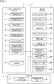
Fig. 4 is a diagram illustrating a configuration of the functions of the vehicle-mountedcontroller 11, themobile controller 21, and theserver controller 31. The vehicle-mountedcontroller 11 is provided with anotification unit 111 and avehicle navigation unit 112. Themobile controller 21 is provided with anintegrated navigation unit 211, anevent determination unit 212, auser reporting unit 213, and a walkingnavigation UI unit 214. Theserver controller 31 is provided with a parkinglot search unit 311 and a walkingnavigation computation unit 312. The vehicle-mountedcontroller 11 realizes thenotification unit 111 and thevehicle navigation unit 112 as a result of the CPU of the vehicle-mounteddevice 1 executing a program stored in the ROM of the vehicle-mounteddevice 1. As a result of the CPU of themobile terminal 2 executing the program stored in the ROM of themobile terminal 2, themobile controller 21 realizes the integratednavigation unit 211, theevent determination unit 212, theuser reporting unit 213, and the walkingnavigation UI unit 214. Theserver controller 31 realizes the parkinglot search unit 311 and the walkingnavigation computation unit 312 as a result of the CPU of theserver 3 executing the program stored in the ROM of theserver 3. - The
notification unit 111 transmits a confirmation required stop notification and a normal stop notification to themobile terminal 2, as will be described in detail subsequently. Thevehicle navigation unit 112 refers to themap DB 19 to calculate a travel route to a destination parking lot which has been input from themobile terminal 2. Thevehicle navigation unit 112 then outputs information of the calculated travel route to the vehicle-mounteddisplay unit 12. Thevehicle navigation unit 112 may update the information displayed on the vehicle-mounteddisplay unit 12 on the basis of position information acquired from the vehicle-mountedGPS receiver 14 and the direction of travel of the own vehicle acquired from thegyro sensor 16. - The
integrated navigation unit 211 integrates vehicle navigation and walking navigation. Theintegrated navigation unit 211 first acquires a destination which is input by the user using themobile input unit 23. Theintegrated navigation unit 211 transmits this destination information to theserver 3 and acquires information on the parking lot nearest to the destination, that is, the destination parking lot. Theintegrated navigation unit 211 then transmits the destination information received from theserver 3 to the vehicle-mounteddevice 1 and causes the vehicle-mounteddevice 1 to execute vehicle navigation. Upon receiving a confirmation required stop notification or a normal stop notification from the vehicle-mounteddevice 1, theintegrated navigation unit 211 then outputs operating instructions to theevent determination unit 212, theuser reporting unit 213, and the walkingnavigation UI unit 214 by means of processing that will be described subsequently. - The
event determination unit 212 determines an event by means of the operating instructions from theintegrated navigation unit 211. Theevent determination unit 212 determines the event that corresponds to the current status among the events listed in the event list table 29A on the basis of the current position output by themobile GPS receiver 24, the destination input by the user, the parking lot determined from the destination, and home information, and so forth. Theuser reporting unit 213 refers to the notification condition table 29B to make reports and inquiries to the user on the basis of the event determined by theevent determination unit 212. Such reports and inquiries are made, as necessary, by using themobile display unit 22, theloudspeaker 22A, and thevibrator 22B. - The walking
navigation UI unit 214 executes walking navigation by using information received from the walkingnavigation computation unit 312 of theserver 3, that is, executes a display of route information on themobile display unit 22. The walkingnavigation UI unit 214 does not perform walking route calculations. The walkingnavigation UI unit 214 may create video information displayed on themobile display unit 22 on the basis of received walking route information and the position information output by themobile GPS receiver 24. Furthermore, each time themobile GPS receiver 24 outputs position information, the walkingnavigation UI unit 214 may transmit the position information to theserver 3 and may receive the video information created by the walkingnavigation computation unit 312 and display the video information on themobile display unit 22. - The parking
lot search unit 311 refers to theserver map DB 39 to search for the parking lot nearest to the destination which has been input from themobile terminal 2. The parkinglot search unit 311 then transmits information representing the parking lot thus searched for, such as, for example, the latitude and longitude of the parking lot, to themobile terminal 2. The walkingnavigation computation unit 312 refers to theserver map DB 39 to calculate the walking route enabling the user to reach the destination on foot on the basis of the current position and destination of themobile terminal 2 which has been input from themobile terminal 2. The walkingnavigation computation unit 312 transmits walking route information to themobile terminal 2. -
Fig. 5 is a diagram illustrating a display screen that is displayed on themobile display unit 22 by theuser reporting unit 213.Fig. 5(a) is a diagram illustrating a vehicle exit confirmation screen,Fig. 5(b) is a diagram illustrating a walking navigation start confirmation screen, andFig. 5(c) is a diagram illustrating a return home time notification screen. A message inquiring whether or not the user has exited the vehicle and "Yes" and "No" options for indicating a response to the message are displayed on the vehicle exit confirmation screen illustrated inFig. 5(a) . The user selects either option to relay to themobile terminal 2 whether or not they have exited the vehicle. - A message inquiring whether or not walking navigation has started and "Yes" and "No" options for indicating a response to the message are displayed on the walking navigation start confirmation screen illustrated in
Fig. 5(b) . When the user selects "Yes", walking navigation is started, and when walking navigation ends, the ETC charge up to that point on the day, a display to the effect that coin-operated parking usage has started, and a coin-operated parking charge are displayed. When the user selects "No", walking navigation is omitted and the ETC charge up to that point on the day, a display to the effect that coin-operated parking usage has started, and a coin-operated parking charge are displayed. - The return home time notification screen illustrated in
Fig. 5(c) displays the fact that a return home start time has been reached and displays a return home time which has been set beforehand. In the notification condition table 29B illustrated inFig. 3 , because the value in the "confirmation" column of the notification condition table 29B is "-", options are not displayed, unlike the walking navigation start confirmation screen illustrated inFig. 5(b) . -
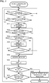
Fig. 6 is a flowchart representing the operation of thenotification unit 111 of the vehicle-mountedcontroller 11. The vehicle-mountedcontroller 11 starts the operation illustrated inFig. 6 when the power supply of the vehicle-mounteddevice 1 is turned on, in a case where the ignition switch of the own vehicle is turned on, and so forth. - The vehicle-mounted
controller 11 first determines in S301 whether or not themobile terminal 2 is connected to the vehicle-mounteddevice 1, in other words, whether or not communication with themobile terminal 2 has been established. When the vehicle-mountedcontroller 11 determines that themobile terminal 2 is connected, that is, when a response to a presence confirmation is received at regular intervals from themobile terminal 2, the vehicle-mountedcontroller 11 advances to S302, and when the vehicle-mountedcontroller 11 determines that themobile terminal 2 is not connected, that is, when a response to a presence confirmation from themobile terminal 2 is interrupted, the vehicle-mountedcontroller 11 remains in S301. In S302, the vehicle-mountedcontroller 11 determines whether or not the power supply of the vehicle-mounteddevice 1 is still in an on state. In other words, in this step, the vehicle-mountedcontroller 11 confirms that the ignition switch of the own vehicle has not been turned off and that the power button of the vehicle-mounteddevice 1 has not been pressed. Upon determining that the power supply is still in an on state, the vehicle-mountedcontroller 11 advances to S303, and upon determining that the power supply is no longer in an on state, the vehicle-mountedcontroller 11 advances to S311. - In S303, the vehicle-mounted
controller 11 determines whether or not the speed of the own vehicle is at or below a predetermined speed, for example at or below 2 km per hour, for a fixed period. Upon determining that the speed of the own vehicle is at or below a predetermined speed for a fixed period, the vehicle-mountedcontroller 11 advances to S304, and upon making a negative determination, the vehicle-mountedcontroller 11 advances to S315. In step S304, the vehicle-mountedcontroller 11 determines, from the position of the own vehicle, which is output by the vehicle-mountedGPS receiver 14, and from information of themap DB 19, whether or not the own vehicle is on the road. For example, an affirmative determination is made in S304 when waiting at a stop light on the road, and a negative determination is made in S304 when the vehicle has stopped in a parking lot. The vehicle-mountedcontroller 11 returns to S301 when an affirmative determination is made in S304 and advances to S305 when a negative determination is made. - In S305, the vehicle-mounted
controller 11 transmits a normal stop notification to themobile terminal 2 via the vehicle-mounted shortrange communication unit 18 and returns to S301. In S311, which is executed when a negative determination is made in S302, the vehicle-mountedcontroller 11 transmits a confirmation required stop notification to themobile terminal 2 via the vehicle-mounted shortrange communication unit 18, and then in S312, performs an end preparation for the vehicle-mounteddevice 1 and ends the operation of the vehicle-mounteddevice 1. Note that the end preparation of the vehicle-mounteddevice 1 is processing in which information stored in the RAM is stored in nonvolatile memory (not illustrated) so as to enable previous processing to be continued when the power supply is then turned on, for example. In S315, which is executed when a negative determination is made in S303, the vehicle-mountedcontroller 11 determines whether or not a normal stop notification has been transmitted. Upon determining that a normal stop notification has been transmitted, the vehicle-mountedcontroller 11 transmits a cancellation instruction to the mobile terminal 2 (S316) and returns to S301. Upon determining that a normal stop notification has not been transmitted, the vehicle-mountedcontroller 11 returns to S301. -
Fig. 7 is a flowchart representing the operation of theintegrated navigation unit 211 of themobile controller 21. More specifically,Fig. 7 is a flowchart representing the operation after theintegrated navigation unit 211 has transmitted destination parking lot information to the vehicle-mounteddevice 1. - In step S321, the
mobile controller 21 first determines whether or not a presence confirmation has been received from the vehicle-mounteddevice 1. When themobile controller 21 determines that a presence confirmation has been received, themobile controller 21 sends back a response to the presence confirmation and advances to S322, and upon determining that a presence confirmation has not been received, themobile controller 21 remains in S321. In S322, themobile controller 21 determines whether or not a stop notification, that is, a normal stop notification or a confirmation required stop notification, has been received from the vehicle-mounteddevice 1. Upon determining that either notification or both notifications have been received, themobile controller 21 advances to S323, and upon determining that neither notification has been received, themobile controller 21 returns to S321. In S323, themobile controller 21 activates themobile accelerometer 25 and, in the next step S324, determines whether or not the output of themobile accelerometer 25 has changed, in other words, whether or not acceleration in any direction has been applied to themobile terminal 2. Upon determining that the output of themobile accelerometer 25 has changed, themobile controller 21 advances to S325, and upon determining that the output has not changed, themobile controller 21 remains in S324. This step focuses on changes in acceleration when the user has exited the vehicle after the own vehicle stops or when the user is moving on foot. - In S325, the
mobile controller 21 determines whether or not a stop notification for which confirmation is required is received, in other words, whether or not the received stop notification is a confirmation required stop notification. Upon determining that a confirmation required stop notification has been received, themobile controller 21 advances to S326 and displays the vehicle exit confirmation screen illustrated inFig. 5(a) on themobile display unit 22. Thereafter, in S327, themobile controller 21 determines whether or not "Yes" has been selected by the user, advancing to S330 upon determining that "Yes" has been selected, and returning to S321 upon determining that "No" has been selected. If a negative determination is made in S325, themobile controller 21 advances to S330. Note that, in cases where both a confirmation required stop notification and a normal stop notification are received, themobile controller 21 prioritizes the normal stop notification and makes a negative determination in S325. - In S330, the
mobile controller 21 makes an event determination and then, in S331, executes a display on the basis of the determined event. Subsequently, in S332, themobile controller 21 determines whether or not the user has selected either option, and upon determining that a selection has been made, advances to S335, performs screen transitions based on the user selection, and ends the processing illustrated inFig. 7 . Upon determining that the user has not made any selection in S332, themobile controller 21 advances to S333. In S333, themobile controller 21 determines whether or not a cancellation instruction has been received from the vehicle-mounteddevice 1. Upon determining that a cancellation instruction has been received, the processing returns to S321, and upon determining that a cancellation instruction has not been received, the processing returns to S332. - According to the foregoing embodiment, the following actions and effects are obtained.
- (1) The vehicle-mounted
device 1 is installed in the own vehicle and is provided with the vehicle-mounted shortrange communication unit 18 that communicates with themobile terminal 2, the vehiclespeed acquiring unit 17 that acquires operation information of the own vehicle, and the vehicle-mountedcontroller 11. On the basis of the operating status of the vehicle-mounteddevice 1, the vehicle-mountedcontroller 11 transmits a first notification notifying themobile terminal 2 of the possibility that the vehicle has stopped, that is, a confirmation required stop notification, to themobile terminal 2 via the vehicle-mounted shortrange communication unit 18. On the basis of the operation information of the own vehicle, the vehicle-mountedcontroller 11 transmits a second notification which is a notification relaying the fact that the own vehicle has stopped to themobile terminal 2, that is, a normal stop notification, to themobile terminal 2 via the vehicle-mounted shortrange communication unit 18. That is, the vehicle-mounteddevice 1 transmits, to themobile terminal 2, not only a normal stop notification issuing notice that the own vehicle has stopped but also a confirmation required stop notification to issue notice of the possibility that the own vehicle has stopped. Hence, the vehicle-mounteddevice 1 is capable of distinguishing between the transmission, to themobile terminal 2, of a confirmation required stop notification and the transmission of a normal stop notification and is capable of notifying themobile terminal 2 of the possibility that the own vehicle has stopped. - (2) The vehicle-mounted
controller 11 transmits a confirmation required stop notification when turning off the power supply of the vehicle-mounteddevice 1. For example, a normal stop notification cannot be transmitted in a case where the ignition switch has been turned off after the driver of the own vehicle has made a sudden stop. However, in such a case, the vehicle-mountedcontroller 11 is capable of transmitting a confirmation required stop notification and of issuing notice of the possibility that the own vehicle has stopped. - (3) The vehicle-mounted
controller 11 transmits a normal stop notification upon determining that the speed of the own vehicle is at or below a predetermined speed for a fixed period and that the own vehicle is not on the road. Hence, the vehicle-mounteddevice 1 is capable of transmitting a normal stop notification if it is probable that the own vehicle has stopped, as in a case where a state of substantially zero speed in a parking lot continues for a predetermined period, or the like. - (4) The vehicle-mounted
controller 11 transmits, to themobile terminal 2, a cancellation instruction which is a signal for canceling a normal stop notification in a case where the speed of the own vehicle is above a predetermined speed and where a normal stop notification has been transmitted (S316 inFig. 6 ). The vehicle-mounteddevice 1 is therefore capable of preventing unnecessary operation of themobile terminal 2. For example, when the vehicle is stopped to settle the bill at the exit from a parking lot and the vehicle starts moving after payment has been made, the vehicle-mounteddevice 1 ends up transmitting a normal stop notification when the vehicle is stopped to settle the bill. In the absence of any countermeasure by the vehicle-mounteddevice 1, themobile controller 21 activates the acceleration sensor (S322: YES, S323), and as a result of the own vehicle traveling, the output of the acceleration sensor changes (S324: YES). In addition, because the notification received by the mobile terminal is a normal stop notification, confirmation is unnecessary (S325: NO) and an event determination and display are executed (S330, S331). However, by transmitting a cancellation instruction to themobile terminal 2, the vehicle-mountedcontroller 11 is able to reset the operation of themobile controller 21, that is, perform recovery to a state before receiving the normal stop notification (S333: YES, S321). Thus, an unnecessary operation such as a display on themobile display unit 22 can be prevented. - (5) The confirmation required stop notification is a notification that causes a person holding the
mobile terminal 2 to confirm that they have exited the own vehicle. Hence, by way of confirmation with the user, themobile terminal 2 is capable of accurately determining that the user has exited the vehicle. - The vehicle-mounted
controller 11 may establish, as a condition, that a confirmation required stop notification, required when the ignition switch is turned off, is transmitted to the mobile terminal 2 (S302: NO, S311 inFig. 6 ) but that a normal stop notification is not transmitted. -
Fig. 8 is a flowchart representing the operation of thenotification unit 111 in a modification example 1.Fig. 8 differs fromFig. 6 in that S319 has been added. S319 is executed when a negative determination is made in S302. In S319, thenotification unit 111 determines whether or not a normal stop notification has been transmitted. Upon determining that a normal stop notification has been transmitted, thenotification unit 111 advances to S312, and upon determining that a normal stop notification has not been transmitted, thenotification unit 111 advances to S311. However, even when a normal stop notification has been transmitted, thenotification unit 111 determines that the normal stop notification has not been transmitted when a cancellation instruction is subsequently transmitted. - According to this modification example, the
mobile terminal 2 does not receive an unnecessary confirmation required stop notification when the ignition switch is turned off, and hence redundant exception handling can be omitted. - The vehicle-mounted short
range communication unit 18 may perform communication with the mobile shortrange communication unit 28A of themobile terminal 2 by using a wired connection such as a USB cable or an IEEE 1394-compatible cable, for example. In this case, the vehicle-mountedcontroller 11 may confirm the presence of themobile terminal 2 by using an electrical characteristic such as a resistance value or a voltage, for example, resulting from the cable connection. - Although the
server 3 is provided with the parkinglot search unit 311 in this embodiment, themobile terminal 2 and the vehicle-mounteddevice 1 may be provided with the parkinglot search unit 311. When themobile terminal 2 is provided with the parkinglot search unit 311, themobile terminal 2 is also provided with a database for searching for a destination parking lot, such as theserver map DB 39, for example. When the vehicle-mounteddevice 1 is provided with the parkinglot search unit 311, themobile terminal 2 transmits information on the destination, which has been input by the user, to the vehicle-mounteddevice 1. - The notification condition table 29B need not be provided with the information in the "confirmation" column, which is the second column from the left of
Fig. 3 . In this case, confirmation may be performed for all notifications, or a screen display may be executed without performing confirmation for all notifications. - In S326 of
Fig. 7 , themobile controller 21 inquires, as illustrated inFig. 5(a) , whether or not the user has exited the own vehicle. However, themobile controller 21 may also inquire whether or not the own vehicle has stopped. - Although it is assumed that a program is stored in a ROM (not illustrated) provided in each device, the program may also be stored in a nonvolatile memory (not illustrated) provided in each device. Furthermore, each device is provided with an I/O (input/output) interface (not illustrated) and, where necessary, a program may be read in from another device via the I/O interface and a medium that can be used by each device. Here, medium refers, for example, to a storage medium that is detachably attached to an I/O interface, or to a communication medium, that is, a network such as a wired, wireless, or optical network, or to a carrier wave or a digital signal that is propagated through the network. Furthermore, some or all of the functions realized by a program may also be realized by a hardware circuit or an FPGA.
- For example, the vehicle-mounted
device 1 may be made to read, directly or via a reading device, a recording medium 204 such as a USB memory or a CD-ROM 904 that stores a program, as illustrated inFig. 9 . The vehicle-mounteddevice 1 may be made to perform reading using a method via acommunication line 901 such as a network. When reading is performed via thecommunication line 901, a program is stored in astorage device 903, or the like, of aserver 902 connected to the communication line. - Each of the foregoing embodiments and modification examples may be combined. Although various embodiments and modification examples have been described hereinabove, the present invention is not limited to the content thereof. Further embodiments conceived within the scope of the technological ideas of the present invention are also included in the scope of the present invention.
- The disclosed content of the following application from which priority is claimed is incorporated herein by reference:
Japanese Patent Application No.2017-216082 (filed on November 9, 2017 -
- 1: Vehicle-mounted device
- 2: Mobile terminal
- 3: Server
- 11: Vehicle-mounted controller
- 18: Vehicle-mounted short range communication unit
- 21: Mobile controller
- 22: Mobile display unit
- 28B: Long range communication unit
- 29B: Notification condition table
- 31: Server controller
- 111: Notification unit
- 112: Vehicle navigation unit
- 211: Integrated navigation unit
- 212: Event determination unit
- 213: User reporting unit
- 214: Walking navigation UI unit
- 311: Parking lot search unit
- 312: Walking navigation computation unit
Claims (11)
- A vehicle-mounted device installed in a vehicle, comprising:a communication unit that communicates with a mobile terminal;a vehicle information acquiring unit that acquires operation information of the vehicle; anda vehicle-mounted controller that, on the basis of an operating status of the vehicle-mounted device, transmits a first notification notifying the mobile terminal of the possibility that the vehicle has stopped to the mobile terminal via the communication unit and that, on the basis of the operation information of the vehicle, transmits a second notification notifying the mobile terminal that the vehicle has stopped to the mobile terminal via the communication unit.
- The vehicle-mounted device according to claim 1, wherein the vehicle-mounted controller transmits the first notification when a power supply of the vehicle-mounted device is turned off.
- The vehicle-mounted device according to claim 1,
wherein the vehicle-mounted controller transmits the second notification upon determining that the speed of the vehicle is at or below a predetermined speed for a fixed period and that the vehicle is not on the road. - The vehicle-mounted device according to claim 3,
wherein the vehicle-mounted controller transmits, to the mobile terminal, a signal for canceling the second notification in a case where the speed of the vehicle is above a predetermined speed and where the second notification has been transmitted. - The vehicle-mounted device according to claim 1,
wherein the first notification is a notification that causes the mobile terminal to confirm that the vehicle has stopped or that a person holding the mobile terminal has exited the vehicle. - A computer-readable recording medium on which is recorded a notification program for causing a vehicle-mounted device that communicates with a mobile terminal installed in a vehicle to execute the steps of:acquiring an operating status of the vehicle-mounted device;acquiring operation information of the vehicle; andtransmitting, on the basis of the operating status of the vehicle-mounted device, a first notification notifying the mobile terminal of the possibility that the vehicle has stopped and transmitting, on the basis of the operation information of the vehicle, a second notification notifying the mobile terminal that the vehicle has stopped, to the mobile term inal.
- A notification method which is executed in a vehicle-mounted device that is installed in a vehicle and that communicates with a mobile terminal, comprising the steps of:acquiring an operating status of the vehicle-mounted device;acquiring operation information of the vehicle; andtransmitting, on the basis of the operating status of the vehicle-mounted device, a first notification notifying the mobile terminal of the possibility that the vehicle has stopped to the mobile terminal and transmitting, on the basis of the operation information of the vehicle, a second notification notifying the mobile terminal that the vehicle has stopped to the mobile terminal.
- The notification method according to claim 7,
wherein the first notification is transmitted when a power supply of the vehicle-mounted device is turned off. - The notification method according to claim 7,
wherein the second notification is transmitted upon determining that the speed of the vehicle is at or below a predetermined speed for a fixed period and that the vehicle is not on the road. - The notification method according to claim 9,
wherein a signal for canceling the second notification is transmitted to the mobile terminal in a case where the speed of the vehicle is above a predetermined speed and where the second notification has been transmitted. - The notification method according to claim 7,
wherein the first notification is a notification that causes the mobile terminal to confirm that the vehicle has stopped or that a person holding the mobile terminal has exited the vehicle.
Applications Claiming Priority (2)
| Application Number | Priority Date | Filing Date | Title |
|---|---|---|---|
| JP2017216082A JP7002293B2 (en) | 2017-11-09 | 2017-11-09 | In-vehicle device, notification program, notification method |
| PCT/JP2018/037223 WO2019093032A1 (en) | 2017-11-09 | 2018-10-04 | Vehicle-mounted device, recording medium, and notification method |
Publications (2)
| Publication Number | Publication Date |
|---|---|
| EP3708957A1 true EP3708957A1 (en) | 2020-09-16 |
| EP3708957A4 EP3708957A4 (en) | 2021-08-04 |
Family
ID=66438298
Family Applications (1)
| Application Number | Title | Priority Date | Filing Date |
|---|---|---|---|
| EP18876443.5A Withdrawn EP3708957A4 (en) | 2017-11-09 | 2018-10-04 | VEHICLE MOUNTED DEVICE, RECORDING MEDIUM AND NOTIFICATION PROCEDURE |
Country Status (5)
| Country | Link |
|---|---|
| US (1) | US11514786B2 (en) |
| EP (1) | EP3708957A4 (en) |
| JP (1) | JP7002293B2 (en) |
| CN (1) | CN111316064B (en) |
| WO (1) | WO2019093032A1 (en) |
Cited By (1)
| Publication number | Priority date | Publication date | Assignee | Title |
|---|---|---|---|---|
| GB2614110A (en) * | 2021-12-21 | 2023-06-28 | Rivian Ip Holdings Llc | Multi-modal navigation system |
Families Citing this family (3)
| Publication number | Priority date | Publication date | Assignee | Title |
|---|---|---|---|---|
| US11842591B2 (en) * | 2019-08-07 | 2023-12-12 | SpotHero, Inc. | Parking facility communication systems and methods |
| KR20220090131A (en) * | 2020-12-22 | 2022-06-29 | 현대자동차주식회사 | Apparatus for on-off control of vehicle condition notification, system having the same and method thereof |
| CN115643602A (en) * | 2022-09-27 | 2023-01-24 | 上汽通用五菱汽车股份有限公司 | In-vehicle communication abnormality early warning method, device, electronic equipment and readable storage medium |
Family Cites Families (12)
| Publication number | Priority date | Publication date | Assignee | Title |
|---|---|---|---|---|
| JP2001317947A (en) * | 2000-03-01 | 2001-11-16 | Matsushita Electric Ind Co Ltd | Navigation device |
| JP2003035551A (en) * | 2001-05-15 | 2003-02-07 | Matsushita Electric Ind Co Ltd | Navigation system |
| US8456326B2 (en) * | 2006-03-24 | 2013-06-04 | Pioneer Corporation | Position registering apparatus, position registering method, position registering program, and recording medium |
| JP5380883B2 (en) | 2008-04-03 | 2014-01-08 | トヨタ自動車株式会社 | In-vehicle device, route guidance system, and route guidance method |
| EP2857265B1 (en) * | 2012-05-31 | 2019-05-22 | Clarion Co., Ltd. | On-board information system, information terminal, and application execution method |
| JP2014202705A (en) * | 2013-04-09 | 2014-10-27 | パナソニック株式会社 | Electronic key, on-vehicle apparatus, guide apparatus and car finder system |
| US9279696B2 (en) * | 2013-10-25 | 2016-03-08 | Qualcomm Incorporated | Automatic handover of positioning parameters from a navigation device to a mobile device |
| JP6295924B2 (en) * | 2014-03-18 | 2018-03-20 | 株式会社デンソー | Vehicle notification control apparatus and vehicle notification control system |
| JP2017116991A (en) * | 2015-12-21 | 2017-06-29 | 京セラ株式会社 | Portable terminal and vehicle |
| JP2017216082A (en) | 2016-05-30 | 2017-12-07 | パナソニックIpマネジメント株式会社 | LED unit and lighting fixture including the same |
| US20180144622A1 (en) * | 2016-11-18 | 2018-05-24 | Toyota Motor Engineering & Manufacturing North America,Inc. | Parking Notification Systems And Methods For Identifying Locations Of Vehicles |
| US10641614B2 (en) * | 2017-06-27 | 2020-05-05 | Toyota Motor Engineering & Manufacturing North America, Inc. | Electronically provided guided tours |
-
2017
- 2017-11-09 JP JP2017216082A patent/JP7002293B2/en active Active
-
2018
- 2018-10-04 EP EP18876443.5A patent/EP3708957A4/en not_active Withdrawn
- 2018-10-04 CN CN201880072317.2A patent/CN111316064B/en active Active
- 2018-10-04 US US16/762,463 patent/US11514786B2/en active Active
- 2018-10-04 WO PCT/JP2018/037223 patent/WO2019093032A1/en not_active Ceased
Cited By (1)
| Publication number | Priority date | Publication date | Assignee | Title |
|---|---|---|---|---|
| GB2614110A (en) * | 2021-12-21 | 2023-06-28 | Rivian Ip Holdings Llc | Multi-modal navigation system |
Also Published As
| Publication number | Publication date |
|---|---|
| US20200365021A1 (en) | 2020-11-19 |
| EP3708957A4 (en) | 2021-08-04 |
| CN111316064B (en) | 2023-10-03 |
| JP2019086446A (en) | 2019-06-06 |
| US11514786B2 (en) | 2022-11-29 |
| CN111316064A (en) | 2020-06-19 |
| JP7002293B2 (en) | 2022-01-20 |
| WO2019093032A1 (en) | 2019-05-16 |
Similar Documents
| Publication | Publication Date | Title |
|---|---|---|
| CN102037330B (en) | Navigation apparatus and method | |
| US10015299B2 (en) | Information display apparatus and information display method | |
| US11835349B2 (en) | Driving support apparatus, driving support system, and driving support method | |
| US11514786B2 (en) | Vehicle-mounted device, recording medium, and notification method | |
| JP2002022478A (en) | Portable type gps receiver, navigator and navigation system | |
| TW201109705A (en) | Satellite signal acquisition apparatus, navigation apparatus and method of acquiring a satellite signal | |
| JPH0962991A (en) | Travel schedule processor | |
| JP2017116991A (en) | Portable terminal and vehicle | |
| US9470547B2 (en) | Information processing device, mobile terminal, and non-transitory recording medium | |
| JP2011232872A (en) | Emergency notification system and emergency notification method | |
| JP2018055535A (en) | Information processing apparatus, information processing method, map display apparatus, map display method, and program | |
| KR101667699B1 (en) | Navigation terminal and method for guiding movement thereof | |
| JP2019159552A (en) | Facility information distribution device and method for distributing facility information | |
| KR101763226B1 (en) | Information providing apparatus and method thereof | |
| US10291728B2 (en) | Location information display system, portable communication terminal, vehicular communication device, and computer program product | |
| JP2020183906A (en) | Vehicle guidance system, on-board unit, and vehicle guidance program | |
| JP4985068B2 (en) | Name display device | |
| JP4692212B2 (en) | Vehicle data necessity determination device and vehicle data notification device |
Legal Events
| Date | Code | Title | Description |
|---|---|---|---|
| STAA | Information on the status of an ep patent application or granted ep patent |
Free format text: STATUS: THE INTERNATIONAL PUBLICATION HAS BEEN MADE |
|
| PUAI | Public reference made under article 153(3) epc to a published international application that has entered the european phase |
Free format text: ORIGINAL CODE: 0009012 |
|
| STAA | Information on the status of an ep patent application or granted ep patent |
Free format text: STATUS: REQUEST FOR EXAMINATION WAS MADE |
|
| 17P | Request for examination filed |
Effective date: 20200608 |
|
| AK | Designated contracting states |
Kind code of ref document: A1 Designated state(s): AL AT BE BG CH CY CZ DE DK EE ES FI FR GB GR HR HU IE IS IT LI LT LU LV MC MK MT NL NO PL PT RO RS SE SI SK SM TR |
|
| AX | Request for extension of the european patent |
Extension state: BA ME |
|
| DAV | Request for validation of the european patent (deleted) | ||
| DAX | Request for extension of the european patent (deleted) | ||
| A4 | Supplementary search report drawn up and despatched |
Effective date: 20210702 |
|
| RIC1 | Information provided on ipc code assigned before grant |
Ipc: G01C 21/26 20060101AFI20210628BHEP Ipc: G08G 1/005 20060101ALI20210628BHEP Ipc: G08G 1/0969 20060101ALI20210628BHEP Ipc: G09B 29/00 20060101ALI20210628BHEP Ipc: G09B 29/10 20060101ALI20210628BHEP Ipc: G01C 21/36 20060101ALI20210628BHEP |
|
| STAA | Information on the status of an ep patent application or granted ep patent |
Free format text: STATUS: EXAMINATION IS IN PROGRESS |
|
| 17Q | First examination report despatched |
Effective date: 20231122 |
|
| STAA | Information on the status of an ep patent application or granted ep patent |
Free format text: STATUS: THE APPLICATION HAS BEEN WITHDRAWN |
|
| 18W | Application withdrawn |
Effective date: 20250901 |