EP3708930B1 - Air conditioner control method and device and air conditioner - Google Patents
Air conditioner control method and device and air conditioner Download PDFInfo
- Publication number
- EP3708930B1 EP3708930B1 EP18910469.8A EP18910469A EP3708930B1 EP 3708930 B1 EP3708930 B1 EP 3708930B1 EP 18910469 A EP18910469 A EP 18910469A EP 3708930 B1 EP3708930 B1 EP 3708930B1
- Authority
- EP
- European Patent Office
- Prior art keywords
- target
- unit
- temperature
- compressor
- load
- Prior art date
- Legal status (The legal status is an assumption and is not a legal conclusion. Google has not performed a legal analysis and makes no representation as to the accuracy of the status listed.)
- Active
Links
Images

Classifications
-
- F—MECHANICAL ENGINEERING; LIGHTING; HEATING; WEAPONS; BLASTING
- F25—REFRIGERATION OR COOLING; COMBINED HEATING AND REFRIGERATION SYSTEMS; HEAT PUMP SYSTEMS; MANUFACTURE OR STORAGE OF ICE; LIQUEFACTION SOLIDIFICATION OF GASES
- F25B—REFRIGERATION MACHINES, PLANTS OR SYSTEMS; COMBINED HEATING AND REFRIGERATION SYSTEMS; HEAT PUMP SYSTEMS
- F25B49/00—Arrangement or mounting of control or safety devices
- F25B49/02—Arrangement or mounting of control or safety devices for compression type machines, plants or systems
- F25B49/022—Compressor control arrangements
-
- F—MECHANICAL ENGINEERING; LIGHTING; HEATING; WEAPONS; BLASTING
- F25—REFRIGERATION OR COOLING; COMBINED HEATING AND REFRIGERATION SYSTEMS; HEAT PUMP SYSTEMS; MANUFACTURE OR STORAGE OF ICE; LIQUEFACTION SOLIDIFICATION OF GASES
- F25B—REFRIGERATION MACHINES, PLANTS OR SYSTEMS; COMBINED HEATING AND REFRIGERATION SYSTEMS; HEAT PUMP SYSTEMS
- F25B49/00—Arrangement or mounting of control or safety devices
-
- F—MECHANICAL ENGINEERING; LIGHTING; HEATING; WEAPONS; BLASTING
- F25—REFRIGERATION OR COOLING; COMBINED HEATING AND REFRIGERATION SYSTEMS; HEAT PUMP SYSTEMS; MANUFACTURE OR STORAGE OF ICE; LIQUEFACTION SOLIDIFICATION OF GASES
- F25B—REFRIGERATION MACHINES, PLANTS OR SYSTEMS; COMBINED HEATING AND REFRIGERATION SYSTEMS; HEAT PUMP SYSTEMS
- F25B39/00—Evaporators; Condensers
-
- F—MECHANICAL ENGINEERING; LIGHTING; HEATING; WEAPONS; BLASTING
- F25—REFRIGERATION OR COOLING; COMBINED HEATING AND REFRIGERATION SYSTEMS; HEAT PUMP SYSTEMS; MANUFACTURE OR STORAGE OF ICE; LIQUEFACTION SOLIDIFICATION OF GASES
- F25B—REFRIGERATION MACHINES, PLANTS OR SYSTEMS; COMBINED HEATING AND REFRIGERATION SYSTEMS; HEAT PUMP SYSTEMS
- F25B49/00—Arrangement or mounting of control or safety devices
- F25B49/02—Arrangement or mounting of control or safety devices for compression type machines, plants or systems
- F25B49/027—Condenser control arrangements
-
- F—MECHANICAL ENGINEERING; LIGHTING; HEATING; WEAPONS; BLASTING
- F25—REFRIGERATION OR COOLING; COMBINED HEATING AND REFRIGERATION SYSTEMS; HEAT PUMP SYSTEMS; MANUFACTURE OR STORAGE OF ICE; LIQUEFACTION SOLIDIFICATION OF GASES
- F25B—REFRIGERATION MACHINES, PLANTS OR SYSTEMS; COMBINED HEATING AND REFRIGERATION SYSTEMS; HEAT PUMP SYSTEMS
- F25B2600/00—Control issues
- F25B2600/02—Compressor control
- F25B2600/024—Compressor control by controlling the electric parameters, e.g. current or voltage
-
- F—MECHANICAL ENGINEERING; LIGHTING; HEATING; WEAPONS; BLASTING
- F25—REFRIGERATION OR COOLING; COMBINED HEATING AND REFRIGERATION SYSTEMS; HEAT PUMP SYSTEMS; MANUFACTURE OR STORAGE OF ICE; LIQUEFACTION SOLIDIFICATION OF GASES
- F25B—REFRIGERATION MACHINES, PLANTS OR SYSTEMS; COMBINED HEATING AND REFRIGERATION SYSTEMS; HEAT PUMP SYSTEMS
- F25B2600/00—Control issues
- F25B2600/02—Compressor control
- F25B2600/025—Compressor control by controlling speed
- F25B2600/0253—Compressor control by controlling speed with variable speed
-
- F—MECHANICAL ENGINEERING; LIGHTING; HEATING; WEAPONS; BLASTING
- F25—REFRIGERATION OR COOLING; COMBINED HEATING AND REFRIGERATION SYSTEMS; HEAT PUMP SYSTEMS; MANUFACTURE OR STORAGE OF ICE; LIQUEFACTION SOLIDIFICATION OF GASES
- F25B—REFRIGERATION MACHINES, PLANTS OR SYSTEMS; COMBINED HEATING AND REFRIGERATION SYSTEMS; HEAT PUMP SYSTEMS
- F25B2600/00—Control issues
- F25B2600/02—Compressor control
- F25B2600/027—Compressor control by controlling pressure
-
- F—MECHANICAL ENGINEERING; LIGHTING; HEATING; WEAPONS; BLASTING
- F25—REFRIGERATION OR COOLING; COMBINED HEATING AND REFRIGERATION SYSTEMS; HEAT PUMP SYSTEMS; MANUFACTURE OR STORAGE OF ICE; LIQUEFACTION SOLIDIFICATION OF GASES
- F25B—REFRIGERATION MACHINES, PLANTS OR SYSTEMS; COMBINED HEATING AND REFRIGERATION SYSTEMS; HEAT PUMP SYSTEMS
- F25B2600/00—Control issues
- F25B2600/17—Control issues by controlling the pressure of the condenser
-
- F—MECHANICAL ENGINEERING; LIGHTING; HEATING; WEAPONS; BLASTING
- F25—REFRIGERATION OR COOLING; COMBINED HEATING AND REFRIGERATION SYSTEMS; HEAT PUMP SYSTEMS; MANUFACTURE OR STORAGE OF ICE; LIQUEFACTION SOLIDIFICATION OF GASES
- F25B—REFRIGERATION MACHINES, PLANTS OR SYSTEMS; COMBINED HEATING AND REFRIGERATION SYSTEMS; HEAT PUMP SYSTEMS
- F25B2700/00—Sensing or detecting of parameters; Sensors therefor
- F25B2700/15—Power, e.g. by voltage or current
- F25B2700/151—Power, e.g. by voltage or current of the compressor motor
-
- F—MECHANICAL ENGINEERING; LIGHTING; HEATING; WEAPONS; BLASTING
- F25—REFRIGERATION OR COOLING; COMBINED HEATING AND REFRIGERATION SYSTEMS; HEAT PUMP SYSTEMS; MANUFACTURE OR STORAGE OF ICE; LIQUEFACTION SOLIDIFICATION OF GASES
- F25B—REFRIGERATION MACHINES, PLANTS OR SYSTEMS; COMBINED HEATING AND REFRIGERATION SYSTEMS; HEAT PUMP SYSTEMS
- F25B2700/00—Sensing or detecting of parameters; Sensors therefor
- F25B2700/19—Pressures
- F25B2700/193—Pressures of the compressor
-
- F—MECHANICAL ENGINEERING; LIGHTING; HEATING; WEAPONS; BLASTING
- F25—REFRIGERATION OR COOLING; COMBINED HEATING AND REFRIGERATION SYSTEMS; HEAT PUMP SYSTEMS; MANUFACTURE OR STORAGE OF ICE; LIQUEFACTION SOLIDIFICATION OF GASES
- F25B—REFRIGERATION MACHINES, PLANTS OR SYSTEMS; COMBINED HEATING AND REFRIGERATION SYSTEMS; HEAT PUMP SYSTEMS
- F25B2700/00—Sensing or detecting of parameters; Sensors therefor
- F25B2700/19—Pressures
- F25B2700/195—Pressures of the condenser
-
- F—MECHANICAL ENGINEERING; LIGHTING; HEATING; WEAPONS; BLASTING
- F25—REFRIGERATION OR COOLING; COMBINED HEATING AND REFRIGERATION SYSTEMS; HEAT PUMP SYSTEMS; MANUFACTURE OR STORAGE OF ICE; LIQUEFACTION SOLIDIFICATION OF GASES
- F25B—REFRIGERATION MACHINES, PLANTS OR SYSTEMS; COMBINED HEATING AND REFRIGERATION SYSTEMS; HEAT PUMP SYSTEMS
- F25B2700/00—Sensing or detecting of parameters; Sensors therefor
- F25B2700/19—Pressures
- F25B2700/197—Pressures of the evaporator
-
- F—MECHANICAL ENGINEERING; LIGHTING; HEATING; WEAPONS; BLASTING
- F25—REFRIGERATION OR COOLING; COMBINED HEATING AND REFRIGERATION SYSTEMS; HEAT PUMP SYSTEMS; MANUFACTURE OR STORAGE OF ICE; LIQUEFACTION SOLIDIFICATION OF GASES
- F25B—REFRIGERATION MACHINES, PLANTS OR SYSTEMS; COMBINED HEATING AND REFRIGERATION SYSTEMS; HEAT PUMP SYSTEMS
- F25B2700/00—Sensing or detecting of parameters; Sensors therefor
- F25B2700/21—Temperatures
-
- F—MECHANICAL ENGINEERING; LIGHTING; HEATING; WEAPONS; BLASTING
- F25—REFRIGERATION OR COOLING; COMBINED HEATING AND REFRIGERATION SYSTEMS; HEAT PUMP SYSTEMS; MANUFACTURE OR STORAGE OF ICE; LIQUEFACTION SOLIDIFICATION OF GASES
- F25B—REFRIGERATION MACHINES, PLANTS OR SYSTEMS; COMBINED HEATING AND REFRIGERATION SYSTEMS; HEAT PUMP SYSTEMS
- F25B2700/00—Sensing or detecting of parameters; Sensors therefor
- F25B2700/21—Temperatures
- F25B2700/2116—Temperatures of a condenser
- F25B2700/21161—Temperatures of a condenser of the fluid heated by the condenser
-
- F—MECHANICAL ENGINEERING; LIGHTING; HEATING; WEAPONS; BLASTING
- F25—REFRIGERATION OR COOLING; COMBINED HEATING AND REFRIGERATION SYSTEMS; HEAT PUMP SYSTEMS; MANUFACTURE OR STORAGE OF ICE; LIQUEFACTION SOLIDIFICATION OF GASES
- F25B—REFRIGERATION MACHINES, PLANTS OR SYSTEMS; COMBINED HEATING AND REFRIGERATION SYSTEMS; HEAT PUMP SYSTEMS
- F25B2700/00—Sensing or detecting of parameters; Sensors therefor
- F25B2700/21—Temperatures
- F25B2700/2117—Temperatures of an evaporator
- F25B2700/21171—Temperatures of an evaporator of the fluid cooled by the evaporator
-
- Y—GENERAL TAGGING OF NEW TECHNOLOGICAL DEVELOPMENTS; GENERAL TAGGING OF CROSS-SECTIONAL TECHNOLOGIES SPANNING OVER SEVERAL SECTIONS OF THE IPC; TECHNICAL SUBJECTS COVERED BY FORMER USPC CROSS-REFERENCE ART COLLECTIONS [XRACs] AND DIGESTS
- Y02—TECHNOLOGIES OR APPLICATIONS FOR MITIGATION OR ADAPTATION AGAINST CLIMATE CHANGE
- Y02B—CLIMATE CHANGE MITIGATION TECHNOLOGIES RELATED TO BUILDINGS, e.g. HOUSING, HOUSE APPLIANCES OR RELATED END-USER APPLICATIONS
- Y02B30/00—Energy efficient heating, ventilation or air conditioning [HVAC]
- Y02B30/70—Efficient control or regulation technologies, e.g. for control of refrigerant flow, motor or heating
Definitions
- the disclosure relates to the field of air conditioners, in particular to an air conditioner control method and device and an air conditioner.
- JP 2007 298235 A describes a method according to the preamble of claim 1; and describes a heat source system provided with: a cooling tower carrying out heat exchange between cooling water and outside air to cool the cooling water; a cooling water bypass passage bypassing the cooling water around the cooling tower; flow regulating valves regulating a flow rate of the cooling water flowing through the cooling water bypass passage; and a system control panel controlling the flow regulating valves on the basis of a cooling water outlet temperature of the cooling water flowing out from a condenser.
- an air conditioner control method comprising: acquiring a current temperature of a chilled water of a unit at a preset period; determining a target load of the unit, a target temperature of the chilled water and a target temperature of a cooling water according to a temperature of the chilled water set by a user and the current temperature of the chilled water; determining an evaporation parameter and a condensation parameter of the unit according to the target load of the unit, the target temperature of the chilled water and the target temperature of the cooling water; and determining operation parameters of a compressor according to the target load of the unit, the evaporation parameter and the condensation parameter for the unit to operate according to the operation parameters.
- the determining the target load of the unit, the target temperature of the chilled water and the target temperature of the cooling water comprises: calculating a difference value between the current temperature of the chilled water and the temperature of the chilled water set by the user; determining the target load of the unit corresponding to the difference value; and determining the target temperature of the chilled water and the target temperature of the cooling water corresponding to the target load of the unit.
- the air conditioner control method further comprises: calculating a temperature difference between the current temperature of the chilled water and a temperature of the chilled water of the unit acquired in the previous period after determining the target load of the unit; determining whether the temperature difference is larger than the difference value; reducing the target load of the unit by a preset magnitude under the condition that the temperature difference is greater than the difference value; and determining the target temperature of the chilled water and the target temperature of the cooling water corresponding to the reduced target load of the unit.
- the air conditioner control method further comprising: increasing the target load of the unit by a preset magnitude under the condition that the temperature difference is less than the difference value; and determining the target temperature of the chilled water and the target temperature of the cooling water corresponding to the increased target load of the unit.
- the target load of the unit comprises an evaporator load and a condenser load; the evaporation parameter of the unit comprises an target evaporation pressure, and the condensation parameter of the unit comprises a target condensation pressure.
- the determining the evaporation parameter and the condensation parameter of the unit comprises: determining the target evaporation pressure according to the evaporator load and the target temperature of the chilled water; and determining the target condensing pressure according to the condenser load and the target temperature of the cooling water.
- the determining the operation parameters of the compressor comprises: obtaining an operation frequency of the compressor according to the target load of the unit, the target evaporation pressure and the target condensation pressure for the compressor to operate at the operation frequency; obtaining an external pressure ratio of the compressor according to the target evaporation pressure and the target condensation pressure; and adjusting a current internal pressure ratio of the compressor in conformity with the external pressure ratio of the compressor.
- the air conditioner control method further comprising: detecting a current power of the compressor as a first power after adjusting the current internal pressure ratio of the compressor; reducing the current internal pressure ratio of the compressor according to a preset magnitude, and detecting the current power of the compressor as a second power; increasing the current internal pressure ratio of the compressor according to a preset magnitude, and detecting the current power of the compressor as a third power; and taking the minimum value of the first power, the second power and the third power as the operation power of the compressor.
- an air conditioner control device comprising: a memory configured to store instructions; a processor coupled to the memory and configured to implement the method of any of the above embodiments based on instructions stored by the memory.
- a non-transitory computer-readable storage medium stores computer instructions which, when executed by a processor, implement the method according to any one of the embodiments.
- any particular value should be construed as exemplary only and not as limiting. Thus, other examples of the exemplary embodiments may have different values.
- the inventors have found through research that a load of an air conditioning system varies with season, climate and the number of people in the room.
- a refrigeration capacity of a chiller unit of the air conditioner needs to be matched with the load, such that the refrigeration capacity needs to be changed correspondingly. Under the condition of continuously changed water temperature and load, the unit cannot operate at the optimal point.
- the present disclosure provides a scheme capable of ensuring that the chiller unit of the air conditioner can operate in the optimal state.
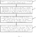
- Fig. 1 is an exemplary flowchart of an air conditioner control method according to one embodiment of the present invention. The steps of the present embodiment may be performed by an air conditioner control device.
- step 101 a current temperature of a chilled water of the unit is acquired at a preset period.
- a target load of the unit, a target temperature of the chilled water and a target temperature of a cooling water are determined according to a temperature of the chilled water set by a user and the current temperature of the chilled water.
- step 102 a difference value ⁇ T between the current temperature of the chilled water and the temperature of the chilled water set by the user is calculated, and the target load of the unit is determined corresponding to the difference value ⁇ T, and the target temperature of the chilled water and target temperature of the cooling water are determined corresponding to the target load of the unit.
- the correspondence relationship between the difference value between the current temperature of the chilled water and the temperature of the chilled water set by the user and the target load of the unit, and the correspondence relationship between the target load of the unit and the target temperature of the chilled water and the target temperature of the cooling water may be obtained through experiments in advance. Therefore, the target load of the unit, the target temperature of the chilled water and the target temperature of the cooling water are determined by using a look-up table.
- the target load of the unit includes an evaporator load and a condenser load.
- step 103 an evaporation parameter and a condensation parameter of the unit are determined according to the target load of the unit, the target temperature of the chilled water and the target temperature of the cooling water.
- the evaporation parameter of the unit comprises an target evaporation pressure and the condensation parameter of the unit comprises a target condensation pressure.
- step 104 operation parameters of the compressor are determined according to the target load of the unit, the evaporation parameter and the condensation parameter, so that the unit can operates according to the operation parameters.
- the air conditioning unit can be efficiently operated by performing optimization control, to ensure high-reliability operation of the whole cold water system.
- a temperature difference between the current temperature of the chilled water and a temperature of the chilled water of the unit acquired in the previous period is further calculated after the target load of the unit is determined, and it is determined whether the temperature difference is greater than the difference value ⁇ T. If the temperature difference is larger than the difference value ⁇ T, the target load of the unit is reduced by a preset magnitude, and the target temperature of the chilled water and target temperature of the cooling water are determined corresponding to the reduced target load of the unit.
- the target load of the unit is increased by a preset magnitude, and the target temperature of the chilled water and the target temperature of the cooling water are determined corresponding to the increased target load of the unit.
- the current temperature of the chilled water of the unit is acquired to be Ta, while the temperature of the chilled water of the unit acquired in the previous operation period is Tb, so that the temperature difference is (Tb-Ta) .
- the target load of the unit is adjusted from Q1 to Q2, wherein Q2 ⁇ Q1.
- the target load of the unit is adjusted from Q1 to Q3, wherein Q3>Q1. Therefore, the overlarge change rate of the temperature of the chilled water can be effectively avoided.
- the target evaporation pressure may be determined based on the evaporator load and the target temperature of the chilled water. And the target condensation pressure is determined according to the condenser load and the target temperature of the cooling water.
- the correlation between the evaporator load, the target temperature of the chilled water, and the target evaporation pressure may be obtained in advance through experiments, and the correlation between the condenser load, the target temperature of the cooling water, and the target condensation pressure may be obtained through experiments, so that the target evaporation pressure and target condensation pressure can be obtained by using a look-up table.
- step 104 the operation parameters of the compressor are determined according to the target load of the unit, the evaporation parameter and the condensation parameter includes:
- the operation frequency of the compressor is obtained according to the target load of the unit, the target evaporation pressure and the target condensation pressure, so that the compressor can operate at the operation frequency.
- the external pressure ratio of the compressor is obtained according to the target evaporation pressure and the target condensation pressure, and the current internal pressure ratio of the compressor is adjusted in conformity with the external pressure ratio of the compressor.
- the correlation between the operation frequency of the compressor and the evaporator load, the condenser load, the evaporation parameter and the condensation parameter may be obtained through experiments in advance. Therefore, the operation frequency of the compressor can be obtained corresponding to the evaporator load, the condenser load, the evaporation parameter and the condensation parameter by using a look-up table.
- the current internal pressure ratio of the compressor can be adjusted in conformity with the external pressure ratio of the compressor by firstly utilizing the target evaporation pressure and the target condensation pressure to obtain the external pressure ratio of the compressor and then adjusting the current internal pressure ratio of the compressor. In this way, coarse adjustment of the internal pressure ratio can be realized.
- a power of the compressor at the moment is W1, i.e., a first power
- the internal pressure ratio is V1.
- the internal pressure ratio is increased by one step to obtain the adj acent internal pressure ratio V2, and the power of the compressor at the moment is W2, i.e., a second power.
- the internal pressure ratio is reduced from V1 by one step to obtain the adjacent internal pressure ratio V3, and the power of the compressor at the moment is W3, i.e., a third power.
- the minimum power value is taken as the operation power of the compressor.
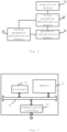
- Fig. 2 is an exemplary block diagram of an air conditioner control device described in the present disclosure. As shown in Fig. 2 , the air conditioner control device includes an acquisition module 21, a first parameter determination module 22, a second parameter determination module 23, and a parameter optimization module 24.
- the acquisition module 21 is configured to acquire a current temperature of a chilled water of a unit at a preset period.
- the first parameter determination module 22 is configured to determine a target load of the unit, a target temperature of the chilled water and a target temperature of a cooling water according to a temperature of the chilled water set by a user and the current temperature of the chilled water.
- the first parameter determination module 22 may be configured to calculate a difference value ⁇ T between the current temperature of the chilled water and the temperature of the chilled water set by a user, determine the target load of the unit according to the difference value ⁇ T, and determine the target temperature of the chilled water and the target temperature of the cooling water corresponding to the target load of the unit.
- the first parameter determination module 22 may be further configured to calculate a temperature difference between the current temperature of the chilled water and a temperature of the chilled water of the unit acquired in the previous period after determining the target load of the unit, and determine whether the temperature difference is greater than the difference value ⁇ T. If the temperature difference is greater than the difference value ⁇ T, the first parameter determination module 22 reduces the target load of the unit by a preset magnitude, and determines the target temperature of the chilled water and the target temperature of the cooling water corresponding to the reduced target load of the unit.
- the first parameter determination module 22 may be further configured to increase the target load of the unit by a preset magnitude if the temperature difference is smaller than the difference value ⁇ T, and determine the target temperature of the chilled water and target temperature of the cooling water corresponding to the increased target load of the unit.
- the target load of the unit may includes an evaporator load and a condenser load.
- the second parameter determination module 23 is configured to determine an evaporation parameter and a condensation parameter of the unit according to the target load of the unit, the target temperature of the chilled water, and the target temperature of the cooling water.
- the evaporation parameter of the unit may comprise an target evaporation pressure and the condensation parameter of the unit comprises a target condensation pressure.
- the second parameter determination module 23 may be configured to determine the target evaporation pressure based on the evaporator load and the target temperature of the chilled water, and determine the target condensation pressure based on the condenser load and the target temperature of the chilled water.
- the parameter optimization module 24 is configured to determine the operation parameters of the compressor based on the target load of the unit, the evaporation parameter and the condensation parameter, so that the unit operates according to the operation parameters.
- the parameter optimization module 24 may be configured to obtain an operation frequency of the compressor according to the target load of the unit, the target evaporation pressure and the target condensation pressure for the compressor to operate at the operation frequency, obtain an external pressure ratio of the compressor according to the target evaporation pressure and the target condensation pressure, and adjust the current internal pressure ratio of the compressor in conformity with the external pressure ratio of the compressor. In this way, coarse adjustment of the internal pressure ratio is realized.
- the parameter optimization module 24 may be further configured to detect a current power W1 of the compressor, i.e., a first power, after adjusting the current internal pressure ratio of the compressor.
- the parameter optimization module 24 decreases the current internal pressure ratio V of the compressor by a preset magnitude and detects the current power W2 of the compressor, i.e., a second power.
- the parameter optimization module 24 increases the current internal pressure ratio V of the compressor by a preset magnitude and detects the current power W3 of the compressor, i.e., a third power.
- the parameter optimization module 24 takes the minimum value among the first power W1, the second power W2 and the third power W3 as the operation power of the compressor, thereby achieving fine adjustment of the internal pressure ratio.
- Fig. 3 is an exemplary block diagram of an air conditioner control device according to another embodiment of the present invention.
- the air conditioner control device includes a memory 31 and a processor 32.
- the memory 31 is used for storing instructions
- the processor 32 is coupled to the memory 31, and the processor 32 is configured to execute the method according to any embodiment in Fig. 1 based on the instructions stored in the memory.
- the air conditioner control device further includes a communication interface 33 for information interaction with other devices.
- the air conditioner control device also comprises a bus 34, and the processor 32, the communication interface 33 and the memory 31 are communicated with each other through the bus 34.
- the memory 31 may comprise high-speed RAM memory, and may also include non-volatile memory, such as at least one disk memory.
- the memory 31 may also be a memory array.
- the storage 31 may also be partitioned into blocks and the blocks may be combined into virtual volumes according to certain rules.
- the processor 32 may be a central processing unit CPU, or may be an application specific integrated circuit ASIC, or one or more integrated circuits configured to implement embodiments of the present invention.
- the present invention also relates to a computer-readable storage medium, in which computer instructions are stored, and when executed by a processor, the instructions implement the method according to any one of the embodiments in Fig. 1 .
- Fig. 4 is an exemplary block diagram of an air conditioner according to one embodiment of the present invention.
- an air conditioner control device 42 is provided in the air conditioner 41.
- the air conditioner control device 42 may be any of the air conditioner control devices described in either of Fig. 2 or Fig. 3 .
- the functional unit modules described above can be implemented as a general purpose Processor, a Programmable Logic Controller (PLC), a Digital Signal Processor (DSP), an Application Specific Integrated Circuit (ASIC), a Field-Programmable Gate Array (FPGA) or other Programmable Logic device, discrete Gate or transistor Logic, discrete hardware components, or any suitable combination thereof for performing the functions described in this disclosure.
- PLC Programmable Logic Controller
- DSP Digital Signal Processor
- ASIC Application Specific Integrated Circuit
- FPGA Field-Programmable Gate Array
- other Programmable Logic device discrete Gate or transistor Logic, discrete hardware components, or any suitable combination thereof for performing the functions described in this disclosure.
- all components of the air conditioning unit can operate in the optimal operation state, so that the high-reliability operation of the air conditioning unit is ensured.
Landscapes
- Engineering & Computer Science (AREA)
- Physics & Mathematics (AREA)
- Mechanical Engineering (AREA)
- Thermal Sciences (AREA)
- General Engineering & Computer Science (AREA)
- Air Conditioning Control Device (AREA)
Description
- The disclosure relates to the field of air conditioners, in particular to an air conditioner control method and device and an air conditioner.
- With the rapid development of national economy, the demand of China for energy is increasing day by day, and the problem of energy shortage is more and more prominent. In many buildings, the energy consumption of the central air conditioning system accounts for a large portion of the total energy consumption of the building.
-
JP 2007 298235 A
a cooling tower carrying out heat exchange between cooling water and outside air to cool the cooling water; a cooling water bypass passage bypassing the cooling water around the cooling tower; flow regulating valves regulating a flow rate of the cooling water flowing through the cooling water bypass passage; and a system control panel controlling the flow regulating valves on the basis of a cooling water outlet temperature of the cooling water flowing out from a condenser. - According to the present invention, there is provided an air conditioner control method according to claim 1. The air conditioner control method comprising: acquiring a current temperature of a chilled water of a unit at a preset period;
determining a target load of the unit, a target temperature of the chilled water and a target temperature of a cooling water according to a temperature of the chilled water set by a user and the current temperature of the chilled water; determining an evaporation parameter and a condensation parameter of the unit according to the target load of the unit, the target temperature of the chilled water and the target temperature of the cooling water; and determining operation parameters of a compressor according to the target load of the unit, the evaporation parameter and the condensation parameter for the unit to operate according to the operation parameters. - In the present invention, the determining the target load of the unit, the target temperature of the chilled water and the target temperature of the cooling water comprises: calculating a difference value between the current temperature of the chilled water and the temperature of the chilled water set by the user; determining the target load of the unit corresponding to the difference value; and determining the target temperature of the chilled water and the target temperature of the cooling water corresponding to the target load of the unit.
- In the present invention, the air conditioner control method further comprises: calculating a temperature difference between the current temperature of the chilled water and a temperature of the chilled water of the unit acquired in the previous period after determining the target load of the unit; determining whether the temperature difference is larger than the difference value; reducing the target load of the unit by a preset magnitude under the condition that the temperature difference is greater than the difference value; and determining the target temperature of the chilled water and the target temperature of the cooling water corresponding to the reduced target load of the unit.
- According to the invention, the air conditioner control method further comprising: increasing the target load of the unit by a preset magnitude under the condition that the temperature difference is less than the difference value; and determining the target temperature of the chilled water and the target temperature of the cooling water corresponding to the increased target load of the unit.
- In some embodiments, the target load of the unit comprises an evaporator load and a condenser load; the evaporation parameter of the unit comprises an target evaporation pressure, and the condensation parameter of the unit comprises a target condensation pressure.
- In some embodiments, the determining the evaporation parameter and the condensation parameter of the unit comprises: determining the target evaporation pressure according to the evaporator load and the target temperature of the chilled water; and determining the target condensing pressure according to the condenser load and the target temperature of the cooling water.
- In some embodiments, the determining the operation parameters of the compressor comprises: obtaining an operation frequency of the compressor according to the target load of the unit, the target evaporation pressure and the target condensation pressure for the compressor to operate at the operation frequency; obtaining an external pressure ratio of the compressor according to the target evaporation pressure and the target condensation pressure; and adjusting a current internal pressure ratio of the compressor in conformity with the external pressure ratio of the compressor.
- In some embodiments, the air conditioner control method further comprising: detecting a current power of the compressor as a first power after adjusting the current internal pressure ratio of the compressor; reducing the current internal pressure ratio of the compressor according to a preset magnitude, and detecting the current power of the compressor as a second power; increasing the current internal pressure ratio of the compressor according to a preset magnitude, and detecting the current power of the compressor as a third power; and taking the minimum value of the first power, the second power and the third power as the operation power of the compressor.
- According to the present invention, there is provided an air conditioner control device according to claim 5, comprising: a memory configured to store instructions; a processor coupled to the memory and configured to implement the method of any of the above embodiments based on instructions stored by the memory.
- According to the present invention, there is provided a non-transitory computer-readable storage medium according to claim 7, wherein the computer-readable storage medium stores computer instructions which, when executed by a processor, implement the method according to any one of the embodiments.
- Other features of the present invention and advantages thereof will become apparent from the following detailed description of exemplary embodiments thereof, which proceeds with reference to the accompanying drawings.
- In order to more clearly illustrate the embodiments of the present invention or the technical solutions in the prior art, the drawings used in the embodiments or the description of the prior art will be briefly described below. Apparently, the drawings in the following description are only some embodiments of the present invention, and for those skilled in the art, other drawings may be obtained according to the drawings without paying inventive labor.
-
Fig. 1 is an exemplary flowchart of an air conditioner control method according to one embodiment of the present invention; -
Fig. 2 is an exemplary block diagram of an air conditioner control device according to the present disclosure; -
Fig. 3 is an exemplary block diagram of an air conditioner control device according to an embodiment of the present invention; -
Fig. 4 is an exemplary block diagram of an air conditioner according to one embodiment of the present invention. - The technical solutions in the embodiments of the present invention will be described clearly and completely with reference to the drawings in the embodiments of the present invention, and it is obvious that the embodiments described are only some, instead of all, of the embodiments of the present invention. The following description of at least one exemplary embodiment is merely illustrative in nature and is in no way intended to limit the invention, its application, or uses.
- Meanwhile, it should be understood that, for the convenience of description, the sizes of the respective portions shown in the drawings are not drawn in an actual proportional relationship.
- Techniques, methods, and devices known to one of ordinary skill in the relevant art may not be discussed in detail but are intended to be part of the authorized specification where appropriate.
- In all examples shown and discussed herein, any particular value should be construed as exemplary only and not as limiting. Thus, other examples of the exemplary embodiments may have different values.
- It should be noted that: similar reference numbers and letters refer to similar items in the following figures, and thus, once an item is defined in one figure, it need not be discussed further in subsequent figures.
- The inventors have found through research that a load of an air conditioning system varies with season, climate and the number of people in the room. A refrigeration capacity of a chiller unit of the air conditioner needs to be matched with the load, such that the refrigeration capacity needs to be changed correspondingly. Under the condition of continuously changed water temperature and load, the unit cannot operate at the optimal point.
- Therefore, the present disclosure provides a scheme capable of ensuring that the chiller unit of the air conditioner can operate in the optimal state.
-
Fig. 1 is an exemplary flowchart of an air conditioner control method according to one embodiment of the present invention. The steps of the present embodiment may be performed by an air conditioner control device. - In
step 101, a current temperature of a chilled water of the unit is acquired at a preset period. - In
step 102, a target load of the unit, a target temperature of the chilled water and a target temperature of a cooling water are determined according to a temperature of the chilled water set by a user and the current temperature of the chilled water. - According to the invention, in
step 102, a difference value ΔT between the current temperature of the chilled water and the temperature of the chilled water set by the user is calculated, and the target load of the unit is determined corresponding to the difference value ΔT, and the target temperature of the chilled water and target temperature of the cooling water are determined corresponding to the target load of the unit. - For example, the correspondence relationship between the difference value between the current temperature of the chilled water and the temperature of the chilled water set by the user and the target load of the unit, and the correspondence relationship between the target load of the unit and the target temperature of the chilled water and the target temperature of the cooling water may be obtained through experiments in advance. Therefore, the target load of the unit, the target temperature of the chilled water and the target temperature of the cooling water are determined by using a look-up table.
- It should be noted that the above embodiment is only used as an example, which does not mean that the disclosure is limited thereto . The person skilled in the art can also perform parameter determination in other realizable manners.
- In some embodiments, the target load of the unit includes an evaporator load and a condenser load.
- In
step 103, an evaporation parameter and a condensation parameter of the unit are determined according to the target load of the unit, the target temperature of the chilled water and the target temperature of the cooling water. - In some embodiments, the evaporation parameter of the unit comprises an target evaporation pressure and the condensation parameter of the unit comprises a target condensation pressure.
- In
step 104, operation parameters of the compressor are determined according to the target load of the unit, the evaporation parameter and the condensation parameter, so that the unit can operates according to the operation parameters. - In the embodiment of the air conditioner control method, the air conditioning unit can be efficiently operated by performing optimization control, to ensure high-reliability operation of the whole cold water system.
- According to the invention, in
step 102, a temperature difference between the current temperature of the chilled water and a temperature of the chilled water of the unit acquired in the previous period is further calculated after the target load of the unit is determined, and it is determined whether the temperature difference is greater than the difference value ΔT. If the temperature difference is larger than the difference value ΔT, the target load of the unit is reduced by a preset magnitude, and the target temperature of the chilled water and target temperature of the cooling water are determined corresponding to the reduced target load of the unit. - If the temperature difference is less than the difference value ΔT, the target load of the unit is increased by a preset magnitude, and the target temperature of the chilled water and the target temperature of the cooling water are determined corresponding to the increased target load of the unit.
- For example, in a certain operation period, the current temperature of the chilled water of the unit is acquired to be Ta, while the temperature of the chilled water of the unit acquired in the previous operation period is Tb, so that the temperature difference is (Tb-Ta) . If (Tb-Ta) is greater than the difference value ΔT between the current temperature of the chilled water and the temperature of the chilled water set by the user, the target load of the unit is adjusted from Q1 to Q2, wherein Q2<Q1. And if (Tb-Ta) is less than the difference value ΔT between the current temperature of the chilled water and the temperature of the chilled water set by the user, the target load of the unit is adjusted from Q1 to Q3, wherein Q3>Q1. Therefore, the overlarge change rate of the temperature of the chilled water can be effectively avoided.
- In some embodiments, in
step 103, the target evaporation pressure may be determined based on the evaporator load and the target temperature of the chilled water. And the target condensation pressure is determined according to the condenser load and the target temperature of the cooling water. - For example, the correlation between the evaporator load, the target temperature of the chilled water, and the target evaporation pressure may be obtained in advance through experiments, and the correlation between the condenser load, the target temperature of the cooling water, and the target condensation pressure may be obtained through experiments, so that the target evaporation pressure and target condensation pressure can be obtained by using a look-up table.
- It should be noted that the above embodiment is only used as an example, which does not mean that the present invention is limited thereto. The person skilled in the art can also perform parameter determination in other realizable manners.
- In some embodiments, in
step 104, the operation parameters of the compressor are determined according to the target load of the unit, the evaporation parameter and the condensation parameter includes: - the operation frequency of the compressor is obtained according to the target load of the unit, the target evaporation pressure and the target condensation pressure, so that the compressor can operate at the operation frequency. The external pressure ratio of the compressor is obtained according to the target evaporation pressure and the target condensation pressure, and the current internal pressure ratio of the compressor is adjusted in conformity with the external pressure ratio of the compressor.
- For example, the correlation between the operation frequency of the compressor and the evaporator load, the condenser load, the evaporation parameter and the condensation parameter may be obtained through experiments in advance. Therefore, the operation frequency of the compressor can be obtained corresponding to the evaporator load, the condenser load, the evaporation parameter and the condensation parameter by using a look-up table.
- In addition, the more approximate the internal pressure ratio of the compressor is to the external pressure ratio, the higher the operation efficiency of the unit. Therefore, the current internal pressure ratio of the compressor can be adjusted in conformity with the external pressure ratio of the compressor by firstly utilizing the target evaporation pressure and the target condensation pressure to obtain the external pressure ratio of the compressor and then adjusting the current internal pressure ratio of the compressor. In this way, coarse adjustment of the internal pressure ratio can be realized.
- It should be noted that, since the pressure ratio varies with a rotation speed as the rotation speed increases, it is necessary to further fine-tune the internal pressure ratio for the compressor to operate at the optimum parameters.
- For example, a power of the compressor at the moment is W1, i.e., a first power, and the internal pressure ratio is V1. The internal pressure ratio is increased by one step to obtain the adj acent internal pressure ratio V2, and the power of the compressor at the moment is W2, i.e., a second power. And then the internal pressure ratio is reduced from V1 by one step to obtain the adjacent internal pressure ratio V3, and the power of the compressor at the moment is W3, i.e., a third power. By comparing the first power W1, the second power W2 and the third power W3, the minimum power value is taken as the operation power of the compressor. Thus, fine adjustment of the internal pressure ratio can be realized.
-
Fig. 2 is an exemplary block diagram of an air conditioner control device described in the present disclosure. As shown inFig. 2 , the air conditioner control device includes anacquisition module 21, a firstparameter determination module 22, a secondparameter determination module 23, and aparameter optimization module 24. - The
acquisition module 21 is configured to acquire a current temperature of a chilled water of a unit at a preset period. - The first
parameter determination module 22 is configured to determine a target load of the unit, a target temperature of the chilled water and a target temperature of a cooling water according to a temperature of the chilled water set by a user and the current temperature of the chilled water. - The first
parameter determination module 22 may be configured to calculate a difference value ΔT between the current temperature of the chilled water and the temperature of the chilled water set by a user, determine the target load of the unit according to the difference value ΔT, and determine the target temperature of the chilled water and the target temperature of the cooling water corresponding to the target load of the unit. - The first
parameter determination module 22 may be further configured to calculate a temperature difference between the current temperature of the chilled water and a temperature of the chilled water of the unit acquired in the previous period after determining the target load of the unit, and determine whether the temperature difference is greater than the difference value ΔT. If the temperature difference is greater than the difference value ΔT, the firstparameter determination module 22 reduces the target load of the unit by a preset magnitude, and determines the target temperature of the chilled water and the target temperature of the cooling water corresponding to the reduced target load of the unit. - The first
parameter determination module 22 may be further configured to increase the target load of the unit by a preset magnitude if the temperature difference is smaller than the difference value ΔT, and determine the target temperature of the chilled water and target temperature of the cooling water corresponding to the increased target load of the unit. - The target load of the unit may includes an evaporator load and a condenser load.
- The second
parameter determination module 23 is configured to determine an evaporation parameter and a condensation parameter of the unit according to the target load of the unit, the target temperature of the chilled water, and the target temperature of the cooling water. - The evaporation parameter of the unit may comprise an target evaporation pressure and the condensation parameter of the unit comprises a target condensation pressure.
- The second
parameter determination module 23 may be configured to determine the target evaporation pressure based on the evaporator load and the target temperature of the chilled water, and determine the target condensation pressure based on the condenser load and the target temperature of the chilled water. - The
parameter optimization module 24 is configured to determine the operation parameters of the compressor based on the target load of the unit, the evaporation parameter and the condensation parameter, so that the unit operates according to the operation parameters. - The
parameter optimization module 24 may be configured to obtain an operation frequency of the compressor according to the target load of the unit, the target evaporation pressure and the target condensation pressure for the compressor to operate at the operation frequency, obtain an external pressure ratio of the compressor according to the target evaporation pressure and the target condensation pressure, and adjust the current internal pressure ratio of the compressor in conformity with the external pressure ratio of the compressor. In this way, coarse adjustment of the internal pressure ratio is realized. - The
parameter optimization module 24 may be further configured to detect a current power W1 of the compressor, i.e., a first power, after adjusting the current internal pressure ratio of the compressor. Theparameter optimization module 24 decreases the current internal pressure ratio V of the compressor by a preset magnitude and detects the current power W2 of the compressor, i.e., a second power. Theparameter optimization module 24 increases the current internal pressure ratio V of the compressor by a preset magnitude and detects the current power W3 of the compressor, i.e., a third power. Theparameter optimization module 24 takes the minimum value among the first power W1, the second power W2 and the third power W3 as the operation power of the compressor, thereby achieving fine adjustment of the internal pressure ratio. -
Fig. 3 is an exemplary block diagram of an air conditioner control device according to another embodiment of the present invention. As shown inFig. 3 , the air conditioner control device includes amemory 31 and aprocessor 32. - The
memory 31 is used for storing instructions, and theprocessor 32 is coupled to thememory 31, and theprocessor 32 is configured to execute the method according to any embodiment inFig. 1 based on the instructions stored in the memory. - As shown in
Fig. 3 , the air conditioner control device further includes acommunication interface 33 for information interaction with other devices. Meanwhile, the air conditioner control device also comprises abus 34, and theprocessor 32, thecommunication interface 33 and thememory 31 are communicated with each other through thebus 34. - The
memory 31 may comprise high-speed RAM memory, and may also include non-volatile memory, such as at least one disk memory. Thememory 31 may also be a memory array. Thestorage 31 may also be partitioned into blocks and the blocks may be combined into virtual volumes according to certain rules. - In addition, the
processor 32 may be a central processing unit CPU, or may be an application specific integrated circuit ASIC, or one or more integrated circuits configured to implement embodiments of the present invention. - The present invention also relates to a computer-readable storage medium, in which computer instructions are stored, and when executed by a processor, the instructions implement the method according to any one of the embodiments in
Fig. 1 . -
Fig. 4 is an exemplary block diagram of an air conditioner according to one embodiment of the present invention. As shown inFig. 4 , an airconditioner control device 42 is provided in theair conditioner 41. In some embodiments, the airconditioner control device 42 may be any of the air conditioner control devices described in either ofFig. 2 or Fig. 3 . - In some embodiments, the functional unit modules described above can be implemented as a general purpose Processor, a Programmable Logic Controller (PLC), a Digital Signal Processor (DSP), an Application Specific Integrated Circuit (ASIC), a Field-Programmable Gate Array (FPGA) or other Programmable Logic device, discrete Gate or transistor Logic, discrete hardware components, or any suitable combination thereof for performing the functions described in this disclosure.
- By implementing the present disclosure, all components of the air conditioning unit can operate in the optimal operation state, so that the high-reliability operation of the air conditioning unit is ensured.
- It will be understood by those skilled in the art that all or part of the steps for implementing the above embodiments may be implemented by hardware, or may be implemented by a program instructing relevant hardware, where the program may be stored in a computer-readable storage medium which may be a read-only memory, a magnetic disk or an optical disk.
- The description of the present disclosure has been presented for purposes of illustration and description, and is not intended to be exhaustive or limited to the disclosure in the form disclosed. Many modifications and variations will be apparent to those of ordinary skill in this art. The embodiments were chosen and described in order to best explain the principles of the invention and the practical application, and to enable those of ordinary skill in the art to understand the invention thereby to design various embodiments with different modifications suitable for particular uses.
Claims (7)
- An air conditioner control method, comprising:acquiring a current temperature of a chilled water of a unit at a preset period(101);calculating a difference value between the current temperature of the chilled water and the temperature of the chilled water set by the user;determining the target load of the unit corresponding to the difference value;the air conditioner control method being characterised by comprising:determining the target temperature of the chilled water and the target temperature of the cooling water corresponding to the target load of the unit;determining an evaporation parameter and a condensation parameter of the unit according to the target load of the unit, the target temperature of the chilled water and the target temperature of the cooling water(103);determining operation parameters of a compressor according to the target load of the unit, the evaporation parameter and the condensation parameter for the unit to operate according to the operation parameters(104),calculating a temperature difference between the current temperature of the chilled water and a temperature of the chilled water of the unit acquired in the previous period after determining the target load of the unit;determining whether the temperature difference is larger than the difference value;reducing the target load of the unit by a preset magnitude under the condition that the temperature difference is greater than the difference value; anddetermining the target temperature of the chilled water and the target temperature of the cooling water corresponding to the reduced target load of the unit;increasing the target load of the unit by a preset magnitude under the condition that the temperature difference is less than the difference value; anddetermining the target temperature of the chilled water and the target temperature of the cooling water corresponding to the increased target load of the unit.
- The air conditioner control method according to claim 1, characterized in that:the target load of the unit comprises an evaporator load and a condenser load; andthe evaporation parameter of the unit comprises an target evaporation pressure, and the condensation parameter of the unit comprises a target condensation pressure.
- The air conditioner control method according to claim 2, characterized in that the determining the evaporation parameter and the condensation parameter of the unit comprises:determining the target evaporation pressure according to the evaporator load and the target temperature of the chilled water; anddetermining the target condensing pressure according to the condenser load and the target temperature of the cooling water; the determining the operation parameters of the compressor comprises:obtaining an operation frequency of the compressor according to the target load of the unit, the target evaporation pressure and the target condensation pressure for the compressor to operate at the operation frequency;obtaining an external pressure ratio of the compressor according to the target evaporation pressure and the target condensation pressure; andadjusting a current internal pressure ratio of the compressor in conformity with the external pressure ratio of the compressor.
- The air conditioner control method as claimed in claim 3, characterized by further comprising:detecting a current power of the compressor as a first power after adjusting the current internal pressure ratio of the compressor;reducing the current internal pressure ratio of the compressor according to a preset magnitude, and detecting the current power of the compressor as a second power;increasing the current internal pressure ratio of the compressor according to a preset magnitude, and detecting the current power of the compressor as a third power; andtaking the minimum value of the first power, the second power and the third power as the operation power of the compressor.
- An air conditioner control device, characterized by comprising:a memory(32) configured to store instructions;a processor(31) coupled to the memory(32) and configured to implement the method of any of claims 1-4 based on instructions stored by the memory(32) .
- An air conditioner, characterized by comprising: the air conditioner control device(42) according to claim 5.
- A non-transitory computer readable storage medium, characterized in that the computer readable storage medium stores computer instructions which, when executed by a processor, implement the method of any one of claims 1-4.
Applications Claiming Priority (2)
| Application Number | Priority Date | Filing Date | Title |
|---|---|---|---|
| CN201810230354.3A CN108444159B (en) | 2018-03-20 | 2018-03-20 | Air conditioner control method and device and air conditioner |
| PCT/CN2018/120559 WO2019179177A1 (en) | 2018-03-20 | 2018-12-12 | Air conditioner control method and device and air conditioner |
Publications (3)
| Publication Number | Publication Date |
|---|---|
| EP3708930A1 EP3708930A1 (en) | 2020-09-16 |
| EP3708930A4 EP3708930A4 (en) | 2021-03-17 |
| EP3708930B1 true EP3708930B1 (en) | 2023-02-15 |
Family
ID=63195453
Family Applications (1)
| Application Number | Title | Priority Date | Filing Date |
|---|---|---|---|
| EP18910469.8A Active EP3708930B1 (en) | 2018-03-20 | 2018-12-12 | Air conditioner control method and device and air conditioner |
Country Status (4)
| Country | Link |
|---|---|
| US (1) | US11187448B2 (en) |
| EP (1) | EP3708930B1 (en) |
| CN (1) | CN108444159B (en) |
| WO (1) | WO2019179177A1 (en) |
Families Citing this family (16)
| Publication number | Priority date | Publication date | Assignee | Title |
|---|---|---|---|---|
| CN108444159B (en) | 2018-03-20 | 2019-11-08 | 珠海格力电器股份有限公司 | Air conditioner control method and device and air conditioner |
| CN109556225B (en) * | 2018-10-31 | 2020-07-17 | 珠海格力电器股份有限公司 | Control method for refrigerating capacity of cooling system and cooling system |
| CN109654688B (en) * | 2018-12-21 | 2020-08-11 | 珠海格力电器股份有限公司 | Method and system for adjusting output power of air conditioning unit and air conditioning unit |
| CN111412624A (en) * | 2020-03-20 | 2020-07-14 | 青岛海尔空调电子有限公司 | Air conditioning unit and its compressor frequency control method |
| CN111678240B (en) * | 2020-06-18 | 2021-11-30 | 重庆美的通用制冷设备有限公司 | Operation control method of air conditioner, air conditioner and readable storage medium |
| CN112797668A (en) * | 2020-12-31 | 2021-05-14 | 青岛海尔空调电子有限公司 | Water-cooled heat pump unit and control method thereof |
| CN112902516B (en) * | 2021-03-08 | 2022-10-21 | 深圳市东洋冷冻设备有限公司 | Control method of water chiller, water chiller and storage medium |
| CN113739358A (en) * | 2021-08-31 | 2021-12-03 | 广州汇电云联互联网科技有限公司 | Energy-saving control method and system for cold machine |
| CN114236273A (en) * | 2021-12-02 | 2022-03-25 | 长沙格力暖通制冷设备有限公司 | Performance detection method and device and detection equipment |
| CN114659236B (en) * | 2022-04-29 | 2023-11-21 | 深圳市英维克信息技术有限公司 | Energy-saving control method, device, equipment and storage medium |
| CN115682572B (en) * | 2022-11-07 | 2024-08-16 | 珠海格力电器股份有限公司 | Method, device and equipment for determining load and controlling loading and unloading of chilled water unit |
| CN116678075B (en) * | 2023-06-07 | 2025-07-25 | 香江科技(集团)股份有限公司 | Energy-saving control method and system for air conditioner |
| CN116697630B (en) * | 2023-06-25 | 2025-09-09 | 西安交通大学 | Energy-saving optimization method and system for cascade refrigeration system based on compressor flow regulation |
| CN117515786A (en) * | 2023-10-17 | 2024-02-06 | 福建省数字福建云计算运营有限公司 | A control method and system for adding and subtracting machines of refrigeration units |
| CN117073128B (en) * | 2023-10-19 | 2024-01-26 | 深圳市威磁智能科技有限公司 | Building temperature control method, device and system |
| CN118066684A (en) * | 2024-03-11 | 2024-05-24 | 重庆美的通用制冷设备有限公司 | Air conditioning unit and control method thereof, electronic device, and storage medium |
Family Cites Families (23)
| Publication number | Priority date | Publication date | Assignee | Title |
|---|---|---|---|---|
| JP4690935B2 (en) * | 2006-05-01 | 2011-06-01 | 三菱重工業株式会社 | Heat source system and control method thereof |
| CN101363653A (en) * | 2008-08-22 | 2009-02-11 | 日滔贸易(上海)有限公司 | Energy consumption control method and device of central air-conditioning refrigeration system |
| JP2010210222A (en) | 2009-03-12 | 2010-09-24 | Mitsubishi Heavy Ind Ltd | Air conditioner and its control method |
| CN101968250B (en) * | 2010-10-13 | 2012-12-05 | 濠信节能科技(上海)有限公司 | Energy-saving optimized control system and method for refrigerator room |
| JP5514088B2 (en) | 2010-11-29 | 2014-06-04 | 荏原冷熱システム株式会社 | Turbo refrigerator system |
| US9915453B2 (en) * | 2012-02-07 | 2018-03-13 | Systecon, Inc. | Indirect evaporative cooling system with supplemental chiller that can be bypassed |
| CN202547019U (en) | 2012-04-10 | 2012-11-21 | 陈好 | Energy saving system for central air conditioner |
| US9417638B2 (en) * | 2012-12-20 | 2016-08-16 | Automotive Research & Testing Center | Intelligent thermostatic control method and device for an air conditioner blowing cold and hot air |
| JP5984703B2 (en) | 2013-01-31 | 2016-09-06 | 三菱重工業株式会社 | Control device and control method for heat source system and cooling water supply device |
| CN104315673B (en) | 2014-09-16 | 2017-07-11 | 珠海格力电器股份有限公司 | Fuzzy control system and method for central air conditioner |
| CN104359195B (en) * | 2014-12-31 | 2017-03-08 | 江苏联宏自动化系统工程有限公司 | Based on the central air-conditioning freezing water controling method that dynamic response end total load changes |
| CN106765855B (en) | 2015-11-20 | 2020-04-10 | 维谛技术有限公司 | Control device and method for air conditioning system and air conditioning system |
| CN105387570B (en) * | 2015-11-30 | 2018-03-27 | 珠海格力电器股份有限公司 | Execution capacity adjusting method and device of water chilling unit |
| CN105444482B (en) * | 2015-12-11 | 2019-01-18 | 重庆美的通用制冷设备有限公司 | Water cooled chiller and its saving-energy operation control method |
| CN105423498B (en) * | 2015-12-21 | 2018-01-23 | 珠海格力电器股份有限公司 | Control method of air conditioning system and air conditioning system |
| CN105650808B (en) * | 2015-12-29 | 2018-11-27 | 深圳市奥宇节能技术股份有限公司 | The regulation method and apparatus of water cooler chilled water leaving water temperature |
| CN205807750U (en) * | 2016-06-29 | 2016-12-14 | 启明天工(苏州)控制系统有限公司 | Cold group control energy-saving control system and air-conditioning equipment |
| CN106547858A (en) * | 2016-10-21 | 2017-03-29 | 珠海格力电器股份有限公司 | Big data analysis method for air conditioning unit and air conditioning unit |
| CN107084543A (en) * | 2017-06-06 | 2017-08-22 | 珠海格力电器股份有限公司 | Water-cooling water chilling unit and control method thereof |
| CN107192097A (en) * | 2017-06-06 | 2017-09-22 | 珠海格力电器股份有限公司 | Control method and device for air-conditioning chilled water system |
| CN107421062A (en) | 2017-07-10 | 2017-12-01 | 广东美的暖通设备有限公司 | Air-conditioning system, modification method and computer-readable recording medium can be needed |
| CN107560258A (en) * | 2017-08-28 | 2018-01-09 | 珠海格力电器股份有限公司 | Performance evaluation method of water chilling unit and water chilling unit |
| CN108444159B (en) | 2018-03-20 | 2019-11-08 | 珠海格力电器股份有限公司 | Air conditioner control method and device and air conditioner |
-
2018
- 2018-03-20 CN CN201810230354.3A patent/CN108444159B/en active Active
- 2018-12-12 EP EP18910469.8A patent/EP3708930B1/en active Active
- 2018-12-12 US US16/962,557 patent/US11187448B2/en active Active
- 2018-12-12 WO PCT/CN2018/120559 patent/WO2019179177A1/en not_active Ceased
Also Published As
| Publication number | Publication date |
|---|---|
| EP3708930A1 (en) | 2020-09-16 |
| EP3708930A4 (en) | 2021-03-17 |
| US20200408449A1 (en) | 2020-12-31 |
| CN108444159A (en) | 2018-08-24 |
| CN108444159B (en) | 2019-11-08 |
| WO2019179177A1 (en) | 2019-09-26 |
| US11187448B2 (en) | 2021-11-30 |
Similar Documents
| Publication | Publication Date | Title |
|---|---|---|
| US11187448B2 (en) | Air conditioner control method including determination of a chiller target load | |
| EP3708920B1 (en) | Control method and device for air conditioning system and air conditioning system | |
| CN110949088B (en) | Automobile electronic expansion valve control method and device and heat pump system | |
| US9612601B2 (en) | Systems and methods for adaptive capacity constraint management | |
| CN104246395B (en) | Refrigeration cycle device | |
| CN105953369B (en) | A method and device for controlling an inverter air conditioner | |
| CN104990222B (en) | Air conditioning control method and device | |
| EP2716989A1 (en) | Temperature adjusting system, air conditioning system, and control method | |
| CN110986276A (en) | Water multi-connected system anti-freezing control method, computer readable storage medium and air conditioner | |
| CN105588256B (en) | A kind of control method and device of VRF Air Conditioning System | |
| CN115751514B (en) | An air conditioning system and a method for controlling reheat and dehumidification in an air conditioning system. | |
| EP3411642B1 (en) | A method for controlling a fan of a vapour compression system in accordance with a variable temperature setpoint | |
| CN113280463A (en) | Air conditioner control method for improving indoor comfort, air conditioner and storage medium | |
| EP2839226B1 (en) | A heat rejecting heat exchanger and a method of controlling one or more fans thereof | |
| CN106482295A (en) | Indoor fan control method and device | |
| JPH05322335A (en) | Automatic cooling stopping sequency | |
| CN106403175B (en) | Control method of water chilling unit and water chilling unit | |
| CN110736272A (en) | Control method and control device for air make-up enthalpy increase of air conditioner and air conditioner | |
| EP3532779B1 (en) | A method for controlling a compressor of a heat pump | |
| CN110736214A (en) | Control method and control device for defrosting of air conditioner and air conditioner | |
| CN115871407B (en) | Thermal management system and control method thereof | |
| CN115556532A (en) | Control method of thermal management system | |
| JP2006046839A (en) | Cold and hot water transfer system | |
| CN115930407B (en) | Air conditioner control method and control device, air conditioner system and storage medium | |
| JP2004294022A (en) | Air conditioner |
Legal Events
| Date | Code | Title | Description |
|---|---|---|---|
| STAA | Information on the status of an ep patent application or granted ep patent |
Free format text: STATUS: THE INTERNATIONAL PUBLICATION HAS BEEN MADE |
|
| PUAI | Public reference made under article 153(3) epc to a published international application that has entered the european phase |
Free format text: ORIGINAL CODE: 0009012 |
|
| STAA | Information on the status of an ep patent application or granted ep patent |
Free format text: STATUS: REQUEST FOR EXAMINATION WAS MADE |
|
| 17P | Request for examination filed |
Effective date: 20200608 |
|
| AK | Designated contracting states |
Kind code of ref document: A1 Designated state(s): AL AT BE BG CH CY CZ DE DK EE ES FI FR GB GR HR HU IE IS IT LI LT LU LV MC MK MT NL NO PL PT RO RS SE SI SK SM TR |
|
| AX | Request for extension of the european patent |
Extension state: BA ME |
|
| A4 | Supplementary search report drawn up and despatched |
Effective date: 20210212 |
|
| RIC1 | Information provided on ipc code assigned before grant |
Ipc: F24F 11/00 20180101ALI20210208BHEP Ipc: F25B 49/00 20060101AFI20210208BHEP |
|
| DAV | Request for validation of the european patent (deleted) | ||
| DAX | Request for extension of the european patent (deleted) | ||
| GRAP | Despatch of communication of intention to grant a patent |
Free format text: ORIGINAL CODE: EPIDOSNIGR1 |
|
| STAA | Information on the status of an ep patent application or granted ep patent |
Free format text: STATUS: GRANT OF PATENT IS INTENDED |
|
| INTG | Intention to grant announced |
Effective date: 20220915 |
|
| GRAS | Grant fee paid |
Free format text: ORIGINAL CODE: EPIDOSNIGR3 |
|
| GRAA | (expected) grant |
Free format text: ORIGINAL CODE: 0009210 |
|
| STAA | Information on the status of an ep patent application or granted ep patent |
Free format text: STATUS: THE PATENT HAS BEEN GRANTED |
|
| AK | Designated contracting states |
Kind code of ref document: B1 Designated state(s): AL AT BE BG CH CY CZ DE DK EE ES FI FR GB GR HR HU IE IS IT LI LT LU LV MC MK MT NL NO PL PT RO RS SE SI SK SM TR |
|
| REG | Reference to a national code |
Ref country code: CH Ref legal event code: EP Ref country code: GB Ref legal event code: FG4D |
|
| REG | Reference to a national code |
Ref country code: DE Ref legal event code: R096 Ref document number: 602018046288 Country of ref document: DE |
|
| REG | Reference to a national code |
Ref country code: AT Ref legal event code: REF Ref document number: 1548424 Country of ref document: AT Kind code of ref document: T Effective date: 20230315 Ref country code: IE Ref legal event code: FG4D |
|
| REG | Reference to a national code |
Ref country code: LT Ref legal event code: MG9D |
|
| REG | Reference to a national code |
Ref country code: NL Ref legal event code: MP Effective date: 20230215 |
|
| P01 | Opt-out of the competence of the unified patent court (upc) registered |
Effective date: 20230530 |
|
| REG | Reference to a national code |
Ref country code: AT Ref legal event code: MK05 Ref document number: 1548424 Country of ref document: AT Kind code of ref document: T Effective date: 20230215 |
|
| PG25 | Lapsed in a contracting state [announced via postgrant information from national office to epo] |
Ref country code: RS Free format text: LAPSE BECAUSE OF FAILURE TO SUBMIT A TRANSLATION OF THE DESCRIPTION OR TO PAY THE FEE WITHIN THE PRESCRIBED TIME-LIMIT Effective date: 20230215 Ref country code: PT Free format text: LAPSE BECAUSE OF FAILURE TO SUBMIT A TRANSLATION OF THE DESCRIPTION OR TO PAY THE FEE WITHIN THE PRESCRIBED TIME-LIMIT Effective date: 20230615 Ref country code: NO Free format text: LAPSE BECAUSE OF FAILURE TO SUBMIT A TRANSLATION OF THE DESCRIPTION OR TO PAY THE FEE WITHIN THE PRESCRIBED TIME-LIMIT Effective date: 20230515 Ref country code: NL Free format text: LAPSE BECAUSE OF FAILURE TO SUBMIT A TRANSLATION OF THE DESCRIPTION OR TO PAY THE FEE WITHIN THE PRESCRIBED TIME-LIMIT Effective date: 20230215 Ref country code: LV Free format text: LAPSE BECAUSE OF FAILURE TO SUBMIT A TRANSLATION OF THE DESCRIPTION OR TO PAY THE FEE WITHIN THE PRESCRIBED TIME-LIMIT Effective date: 20230215 Ref country code: LT Free format text: LAPSE BECAUSE OF FAILURE TO SUBMIT A TRANSLATION OF THE DESCRIPTION OR TO PAY THE FEE WITHIN THE PRESCRIBED TIME-LIMIT Effective date: 20230215 Ref country code: HR Free format text: LAPSE BECAUSE OF FAILURE TO SUBMIT A TRANSLATION OF THE DESCRIPTION OR TO PAY THE FEE WITHIN THE PRESCRIBED TIME-LIMIT Effective date: 20230215 Ref country code: ES Free format text: LAPSE BECAUSE OF FAILURE TO SUBMIT A TRANSLATION OF THE DESCRIPTION OR TO PAY THE FEE WITHIN THE PRESCRIBED TIME-LIMIT Effective date: 20230215 Ref country code: AT Free format text: LAPSE BECAUSE OF FAILURE TO SUBMIT A TRANSLATION OF THE DESCRIPTION OR TO PAY THE FEE WITHIN THE PRESCRIBED TIME-LIMIT Effective date: 20230215 |
|
| PG25 | Lapsed in a contracting state [announced via postgrant information from national office to epo] |
Ref country code: SE Free format text: LAPSE BECAUSE OF FAILURE TO SUBMIT A TRANSLATION OF THE DESCRIPTION OR TO PAY THE FEE WITHIN THE PRESCRIBED TIME-LIMIT Effective date: 20230215 Ref country code: PL Free format text: LAPSE BECAUSE OF FAILURE TO SUBMIT A TRANSLATION OF THE DESCRIPTION OR TO PAY THE FEE WITHIN THE PRESCRIBED TIME-LIMIT Effective date: 20230215 Ref country code: IS Free format text: LAPSE BECAUSE OF FAILURE TO SUBMIT A TRANSLATION OF THE DESCRIPTION OR TO PAY THE FEE WITHIN THE PRESCRIBED TIME-LIMIT Effective date: 20230615 Ref country code: GR Free format text: LAPSE BECAUSE OF FAILURE TO SUBMIT A TRANSLATION OF THE DESCRIPTION OR TO PAY THE FEE WITHIN THE PRESCRIBED TIME-LIMIT Effective date: 20230516 Ref country code: FI Free format text: LAPSE BECAUSE OF FAILURE TO SUBMIT A TRANSLATION OF THE DESCRIPTION OR TO PAY THE FEE WITHIN THE PRESCRIBED TIME-LIMIT Effective date: 20230215 |
|
| PG25 | Lapsed in a contracting state [announced via postgrant information from national office to epo] |
Ref country code: SM Free format text: LAPSE BECAUSE OF FAILURE TO SUBMIT A TRANSLATION OF THE DESCRIPTION OR TO PAY THE FEE WITHIN THE PRESCRIBED TIME-LIMIT Effective date: 20230215 Ref country code: RO Free format text: LAPSE BECAUSE OF FAILURE TO SUBMIT A TRANSLATION OF THE DESCRIPTION OR TO PAY THE FEE WITHIN THE PRESCRIBED TIME-LIMIT Effective date: 20230215 Ref country code: EE Free format text: LAPSE BECAUSE OF FAILURE TO SUBMIT A TRANSLATION OF THE DESCRIPTION OR TO PAY THE FEE WITHIN THE PRESCRIBED TIME-LIMIT Effective date: 20230215 Ref country code: DK Free format text: LAPSE BECAUSE OF FAILURE TO SUBMIT A TRANSLATION OF THE DESCRIPTION OR TO PAY THE FEE WITHIN THE PRESCRIBED TIME-LIMIT Effective date: 20230215 Ref country code: CZ Free format text: LAPSE BECAUSE OF FAILURE TO SUBMIT A TRANSLATION OF THE DESCRIPTION OR TO PAY THE FEE WITHIN THE PRESCRIBED TIME-LIMIT Effective date: 20230215 |
|
| REG | Reference to a national code |
Ref country code: DE Ref legal event code: R097 Ref document number: 602018046288 Country of ref document: DE |
|
| PG25 | Lapsed in a contracting state [announced via postgrant information from national office to epo] |
Ref country code: SK Free format text: LAPSE BECAUSE OF FAILURE TO SUBMIT A TRANSLATION OF THE DESCRIPTION OR TO PAY THE FEE WITHIN THE PRESCRIBED TIME-LIMIT Effective date: 20230215 |
|
| PLBE | No opposition filed within time limit |
Free format text: ORIGINAL CODE: 0009261 |
|
| STAA | Information on the status of an ep patent application or granted ep patent |
Free format text: STATUS: NO OPPOSITION FILED WITHIN TIME LIMIT |
|
| 26N | No opposition filed |
Effective date: 20231116 |
|
| PG25 | Lapsed in a contracting state [announced via postgrant information from national office to epo] |
Ref country code: SI Free format text: LAPSE BECAUSE OF FAILURE TO SUBMIT A TRANSLATION OF THE DESCRIPTION OR TO PAY THE FEE WITHIN THE PRESCRIBED TIME-LIMIT Effective date: 20230215 |
|
| REG | Reference to a national code |
Ref country code: CH Ref legal event code: PL |
|
| PG25 | Lapsed in a contracting state [announced via postgrant information from national office to epo] |
Ref country code: LU Free format text: LAPSE BECAUSE OF NON-PAYMENT OF DUE FEES Effective date: 20231212 |
|
| PG25 | Lapsed in a contracting state [announced via postgrant information from national office to epo] |
Ref country code: MC Free format text: LAPSE BECAUSE OF FAILURE TO SUBMIT A TRANSLATION OF THE DESCRIPTION OR TO PAY THE FEE WITHIN THE PRESCRIBED TIME-LIMIT Effective date: 20230215 |
|
| REG | Reference to a national code |
Ref country code: BE Ref legal event code: MM Effective date: 20231231 |
|
| PG25 | Lapsed in a contracting state [announced via postgrant information from national office to epo] |
Ref country code: MC Free format text: LAPSE BECAUSE OF FAILURE TO SUBMIT A TRANSLATION OF THE DESCRIPTION OR TO PAY THE FEE WITHIN THE PRESCRIBED TIME-LIMIT Effective date: 20230215 Ref country code: LU Free format text: LAPSE BECAUSE OF NON-PAYMENT OF DUE FEES Effective date: 20231212 |
|
| REG | Reference to a national code |
Ref country code: IE Ref legal event code: MM4A |
|
| PG25 | Lapsed in a contracting state [announced via postgrant information from national office to epo] |
Ref country code: IE Free format text: LAPSE BECAUSE OF NON-PAYMENT OF DUE FEES Effective date: 20231212 |
|
| PG25 | Lapsed in a contracting state [announced via postgrant information from national office to epo] |
Ref country code: BE Free format text: LAPSE BECAUSE OF NON-PAYMENT OF DUE FEES Effective date: 20231231 |
|
| PG25 | Lapsed in a contracting state [announced via postgrant information from national office to epo] |
Ref country code: CH Free format text: LAPSE BECAUSE OF NON-PAYMENT OF DUE FEES Effective date: 20231231 |
|
| PG25 | Lapsed in a contracting state [announced via postgrant information from national office to epo] |
Ref country code: CH Free format text: LAPSE BECAUSE OF NON-PAYMENT OF DUE FEES Effective date: 20231231 Ref country code: BE Free format text: LAPSE BECAUSE OF NON-PAYMENT OF DUE FEES Effective date: 20231231 Ref country code: IE Free format text: LAPSE BECAUSE OF NON-PAYMENT OF DUE FEES Effective date: 20231212 |
|
| PG25 | Lapsed in a contracting state [announced via postgrant information from national office to epo] |
Ref country code: BG Free format text: LAPSE BECAUSE OF FAILURE TO SUBMIT A TRANSLATION OF THE DESCRIPTION OR TO PAY THE FEE WITHIN THE PRESCRIBED TIME-LIMIT Effective date: 20230215 |
|
| PG25 | Lapsed in a contracting state [announced via postgrant information from national office to epo] |
Ref country code: BG Free format text: LAPSE BECAUSE OF FAILURE TO SUBMIT A TRANSLATION OF THE DESCRIPTION OR TO PAY THE FEE WITHIN THE PRESCRIBED TIME-LIMIT Effective date: 20230215 |
|
| PG25 | Lapsed in a contracting state [announced via postgrant information from national office to epo] |
Ref country code: CY Free format text: LAPSE BECAUSE OF FAILURE TO SUBMIT A TRANSLATION OF THE DESCRIPTION OR TO PAY THE FEE WITHIN THE PRESCRIBED TIME-LIMIT; INVALID AB INITIO Effective date: 20181212 |
|
| PG25 | Lapsed in a contracting state [announced via postgrant information from national office to epo] |
Ref country code: HU Free format text: LAPSE BECAUSE OF FAILURE TO SUBMIT A TRANSLATION OF THE DESCRIPTION OR TO PAY THE FEE WITHIN THE PRESCRIBED TIME-LIMIT; INVALID AB INITIO Effective date: 20181212 |
|
| PG25 | Lapsed in a contracting state [announced via postgrant information from national office to epo] |
Ref country code: TR Free format text: LAPSE BECAUSE OF FAILURE TO SUBMIT A TRANSLATION OF THE DESCRIPTION OR TO PAY THE FEE WITHIN THE PRESCRIBED TIME-LIMIT Effective date: 20230215 |
|
| PGFP | Annual fee paid to national office [announced via postgrant information from national office to epo] |
Ref country code: GB Payment date: 20251111 Year of fee payment: 8 |
|
| PGFP | Annual fee paid to national office [announced via postgrant information from national office to epo] |
Ref country code: FR Payment date: 20251110 Year of fee payment: 8 |
|
| PGFP | Annual fee paid to national office [announced via postgrant information from national office to epo] |
Ref country code: DE Payment date: 20251222 Year of fee payment: 8 |
|
| PGFP | Annual fee paid to national office [announced via postgrant information from national office to epo] |
Ref country code: IT Payment date: 20251231 Year of fee payment: 8 |