EP3708848B1 - Centrifugal compressor and turbocharger comprising said centrifugal compressor - Google Patents
Centrifugal compressor and turbocharger comprising said centrifugal compressor Download PDFInfo
- Publication number
- EP3708848B1 EP3708848B1 EP17930425.8A EP17930425A EP3708848B1 EP 3708848 B1 EP3708848 B1 EP 3708848B1 EP 17930425 A EP17930425 A EP 17930425A EP 3708848 B1 EP3708848 B1 EP 3708848B1
- Authority
- EP
- European Patent Office
- Prior art keywords
- passage
- scroll
- wall surface
- rotational axis
- diffuser
- Prior art date
- Legal status (The legal status is an assumption and is not a legal conclusion. Google has not performed a legal analysis and makes no representation as to the accuracy of the status listed.)
- Active
Links
Images






Classifications
-
- F—MECHANICAL ENGINEERING; LIGHTING; HEATING; WEAPONS; BLASTING
- F04—POSITIVE - DISPLACEMENT MACHINES FOR LIQUIDS; PUMPS FOR LIQUIDS OR ELASTIC FLUIDS
- F04D—NON-POSITIVE-DISPLACEMENT PUMPS
- F04D17/00—Radial-flow pumps, e.g. centrifugal pumps; Helico-centrifugal pumps
- F04D17/08—Centrifugal pumps
- F04D17/10—Centrifugal pumps for compressing or evacuating
-
- F—MECHANICAL ENGINEERING; LIGHTING; HEATING; WEAPONS; BLASTING
- F02—COMBUSTION ENGINES; HOT-GAS OR COMBUSTION-PRODUCT ENGINE PLANTS
- F02B—INTERNAL-COMBUSTION PISTON ENGINES; COMBUSTION ENGINES IN GENERAL
- F02B39/00—Component parts, details, or accessories relating to, driven charging or scavenging pumps, not provided for in groups F02B33/00 - F02B37/00
-
- F—MECHANICAL ENGINEERING; LIGHTING; HEATING; WEAPONS; BLASTING
- F04—POSITIVE - DISPLACEMENT MACHINES FOR LIQUIDS; PUMPS FOR LIQUIDS OR ELASTIC FLUIDS
- F04D—NON-POSITIVE-DISPLACEMENT PUMPS
- F04D29/00—Details, component parts, or accessories
- F04D29/40—Casings; Connections of working fluid
- F04D29/42—Casings; Connections of working fluid for radial or helico-centrifugal pumps
- F04D29/4206—Casings; Connections of working fluid for radial or helico-centrifugal pumps especially adapted for elastic fluid pumps
-
- F—MECHANICAL ENGINEERING; LIGHTING; HEATING; WEAPONS; BLASTING
- F04—POSITIVE - DISPLACEMENT MACHINES FOR LIQUIDS; PUMPS FOR LIQUIDS OR ELASTIC FLUIDS
- F04D—NON-POSITIVE-DISPLACEMENT PUMPS
- F04D29/00—Details, component parts, or accessories
- F04D29/40—Casings; Connections of working fluid
- F04D29/42—Casings; Connections of working fluid for radial or helico-centrifugal pumps
- F04D29/4206—Casings; Connections of working fluid for radial or helico-centrifugal pumps especially adapted for elastic fluid pumps
- F04D29/4226—Fan casings
- F04D29/4233—Fan casings with volutes extending mainly in axial or radially inward direction
-
- F—MECHANICAL ENGINEERING; LIGHTING; HEATING; WEAPONS; BLASTING
- F04—POSITIVE - DISPLACEMENT MACHINES FOR LIQUIDS; PUMPS FOR LIQUIDS OR ELASTIC FLUIDS
- F04D—NON-POSITIVE-DISPLACEMENT PUMPS
- F04D29/00—Details, component parts, or accessories
- F04D29/40—Casings; Connections of working fluid
- F04D29/42—Casings; Connections of working fluid for radial or helico-centrifugal pumps
- F04D29/44—Fluid-guiding means, e.g. diffusers
- F04D29/441—Fluid-guiding means, e.g. diffusers especially adapted for elastic fluid pumps
-
- F—MECHANICAL ENGINEERING; LIGHTING; HEATING; WEAPONS; BLASTING
- F05—INDEXING SCHEMES RELATING TO ENGINES OR PUMPS IN VARIOUS SUBCLASSES OF CLASSES F01-F04
- F05D—INDEXING SCHEME FOR ASPECTS RELATING TO NON-POSITIVE-DISPLACEMENT MACHINES OR ENGINES, GAS-TURBINES OR JET-PROPULSION PLANTS
- F05D2220/00—Application
- F05D2220/40—Application in turbochargers
-
- F—MECHANICAL ENGINEERING; LIGHTING; HEATING; WEAPONS; BLASTING
- F05—INDEXING SCHEMES RELATING TO ENGINES OR PUMPS IN VARIOUS SUBCLASSES OF CLASSES F01-F04
- F05D—INDEXING SCHEME FOR ASPECTS RELATING TO NON-POSITIVE-DISPLACEMENT MACHINES OR ENGINES, GAS-TURBINES OR JET-PROPULSION PLANTS
- F05D2240/00—Components
- F05D2240/10—Stators
- F05D2240/12—Fluid guiding means, e.g. vanes
-
- F—MECHANICAL ENGINEERING; LIGHTING; HEATING; WEAPONS; BLASTING
- F05—INDEXING SCHEMES RELATING TO ENGINES OR PUMPS IN VARIOUS SUBCLASSES OF CLASSES F01-F04
- F05D—INDEXING SCHEME FOR ASPECTS RELATING TO NON-POSITIVE-DISPLACEMENT MACHINES OR ENGINES, GAS-TURBINES OR JET-PROPULSION PLANTS
- F05D2240/00—Components
- F05D2240/10—Stators
- F05D2240/14—Casings or housings protecting or supporting assemblies within
-
- F—MECHANICAL ENGINEERING; LIGHTING; HEATING; WEAPONS; BLASTING
- F05—INDEXING SCHEMES RELATING TO ENGINES OR PUMPS IN VARIOUS SUBCLASSES OF CLASSES F01-F04
- F05D—INDEXING SCHEME FOR ASPECTS RELATING TO NON-POSITIVE-DISPLACEMENT MACHINES OR ENGINES, GAS-TURBINES OR JET-PROPULSION PLANTS
- F05D2250/00—Geometry
- F05D2250/50—Inlet or outlet
- F05D2250/52—Outlet
Definitions
- the present disclosure relates to a centrifugal compressor and a turbocharger including the centrifugal compressor.
- an object of at least one embodiment of the present disclosure is to provide a centrifugal compressor and a turbocharger including the centrifugal compressor whereby it is possible to improve the efficiency in a low flow rate operating point.
- the flow passage area of the scroll passage gradually decreases from the outlet toward the tongue. Due to this shape of the scroll passage, the inclination angle of the concave arc portion tends to increase as it approximates to the tongue.
- the inclination angle has a local minimum value or a minimum value in the range of the central angle of 30° to 120° where the inclination angle tends to increase if the scroll passage is formed without considering the size of the inclination angle, it is possible to decrease the inclination angle in the range of the central angle of 30° to 210°.
- interference between the swirl flow and the flow of the compressed fluid discharged from the diffuser passage is reduced, and the occurrence of separation in the scroll passage is reduced.
- it is possible to improve the efficiency of the centrifugal compressor in a low flow rate operating point.
- the second passage wall includes: a flat inner wall surface which defines the diffuser passage and is flat and perpendicular to the rotational axis; a convex inner wall surface defining the scroll passage and curved convexly with respect to the scroll passage; at least one concave inner wall surface defining the scroll passage and forming the at least one concave arc portion in the cross-section of the housing formed by the plane that includes the rotational axis, the at least one concave inner wall surface including a radially outermost concave inner wall surface located outermost in the radial direction of the impeller and connected to the convex arc portion; and an end surface connecting the flat inner surface and the convex inner wall surface at an outermost portion of the flat inner surface in the radial direction of the impeller.
- an outer diameter of the diffuser passage about the rotational axis has a distribution in a circumferential direction of the diffuser passage, and the distribution of the outer diameter of the diffuser passage has a local maximum value or a maximum value in a range of the central angle of 30° to 210°.
- a distance from the rotational axis to the scroll center of the scroll passage has a distribution in a circumferential direction of the diffuser passage, and the distribution of the distance has a local minimum value or a minimum value in a range of the central angle of 30° to 210°.
- a turbocharger comprises: the centrifugal compressor described in any one of the above (1) and (3) to (5).
- the angle between the direction of the swirl flow and the flow direction of a compressed fluid discharged from the diffuser passage decreases.
- interference between the swirl flow and the flow of the compressed fluid discharged from the diffuser passage is reduced, and the occurrence of separation in the scroll passage is reduced.
- centrifugal compressor according to an embodiment of the present disclosure will be described by taking a centrifugal compressor of a turbocharger as an example.
- the centrifugal compressor in the present disclosure is not limited to a centrifugal compressor of a turbocharger, and may be any centrifugal compressor which operates alone.
- a fluid to be compressed by the compressor is air in the following description, the fluid may be replaced by any other fluid.
- the centrifugal compressor 1 includes a housing 2 and an impeller 3 rotatably disposed around the rotational axis L within the housing 2.
- the housing 2 includes a scroll part 4 having a scroll passage 5 of spiral shape formed on the outer peripheral side of the impeller 3, a diffuser part 6 having a pair of passage walls 7, i.e., a first passage wall 7a and a second passage wall 7b, spaced from each other in an extension direction of the rotational axis L, and an air inlet part 9 of cylindrical shape.
- the second passage wall 7b is positioned closer to the scroll center O s of the scroll passage 5 than the first passage wall 7a is in the extension direction of the rotational axis L.
- a diffuser passage 8 is formed and communicates with the scroll passage 5 along the circumferential direction of the scroll passage 5 on the radially inner side of the impeller 3.
- Air flowing into the centrifugal compressor 1 through the air inlet part 9 is compressed by the impeller 3 into compressed air.
- the compressed air flows through the diffuser passage 8 into the scroll passage 5 and then passes through the scroll passage 5 and is discharged from the centrifugal compressor 1.
- the circumferential position in the scroll passage 5 from a tongue 4a of the scroll part 4 (see FIG. 2 ) to the outlet of the scroll passage 5 is represented by a central angle ⁇ about the rotational axis L by using the tongue 4a as a reference. Accordingly, the central angle ⁇ representing the circumferential position of the tongue 4a is 0°.
- the flow f 1 of compressed air discharged from the diffuser passage 8 in the vicinity of the tongue 4a swirls and flows through the scroll passage 5 along the inner wall surface of the scroll passage 5.
- this swirl flow f 2 of the compressed air circulates one round along the inner wall surface of the scroll passage 5 (in FIG. 3 , at a position where the central angle ⁇ is 30° approximately)
- the swirl flow f 2 interferes with compressed air f 3 discharged from the diffuser passage 8. This interference is one of factors of separation in the scroll passage 5.
- FIG. 5 shows an exemplary cross-sectional shape of the scroll passage 5 with a reduced inclination angle ⁇ .
- the second passage wall 7b includes a flat inner wall surface 21 which defines the diffuser passage 8 and is flat and perpendicular to the rotational axis L, a flat end surface 22 connected to the radially outermost portion of the flat inner wall surface 21 at right angle, a convex inner wall surface 23 connected to the end surface 22 and curved convexly with respect to the scroll passage 5, and a concave inner wall surface 24 connected to the convex inner wall surface 23 and curved concavely with respect to the scroll passage 5.
- the inner wall surface 5a of the scroll passage 5 is divided into a radially inner portion 5a2 and a radially outer portion 5a3 by a virtual line L' passing through the scroll center O s and parallel to the rotational axis L.
- the end surface 22, the convex inner wall surface 23, and the concave inner wall surface 24 are a part of the portion 5a2 of the inner wall surface 5a.
- Curving convexly with respect to the scroll passage 5 means that the curvature center of a convex arc portion 23a forming the convex inner wall surface 23 is positioned outside the scroll passage 5 in the cross-section of the housing 2 (see FIG. 2 ) including the rotational axis L, and curving concavely with respect to the scroll passage 5 means that the curvature center of a concave arc portion 24a forming the concave inner wall surface 24 is positioned inside the scroll passage 5 in the cross-section of the housing 2 (see FIG. 2 ) including the rotational axis L.
- the present inventors have found that separation is likely to occur in a range of the central angle ⁇ of 30° to 210° by CFD analysis.
- the reason is that when stable swirl flow is generated in the scroll passage 5, the swirl flow in the scroll passage 5 and the flow of the compressed air discharged from the diffuser passage 8 gradually stop interfering with each other, and thus interference is mainly caused on the upstream side in the scroll passage 5. Accordingly, by making the cross-sectional shape of the scroll passage 5 such that the inclination angle ⁇ is small on the upstream side, it is possible to effectively reduce the occurrence of separation.
- the cross-sectional shape of the scroll passage 5 shown in FIG. 5 is the shape of one cross-section of the housing 2 (see FIG. 2 ).
- the cross-sectional shape of the scroll passage 5 changes along the circumferential direction.
- the inclination angle ⁇ changes along the circumferential direction. That is, the inclination angle ⁇ is distributed along the circumferential direction of the scroll passage 5.
- FIG. 6 when the distribution of the inclination angle ⁇ has a minimum value in a range of the circumferential position of the scroll passage 5 where the central angle ⁇ is 30° to 210°, it is possible to effectively reduce the occurrence of separation.
- the distribution of the inclination angle ⁇ may not have the minimum value in the above range, but may have a local minimum value in the range of the central angle ⁇ of 30° to 210°. In other words, in a range of the central angle ⁇ larger than 210°, the distribution of the inclination angle ⁇ may have a value smaller than the local minimum value.
- the outer diameter of the diffuser passage 8 (see FIG. 1 ) is increased locally in the circumferential direction. More specifically, the distribution of the outer diameter of the diffuser passage 8 in the circumferential direction has a local maximum value or a maximum value in the range of the central angle ⁇ of 30° to 210°.
- the end surface 22 of the second passage wall 7b is located on a more radially outer side at a portion where the outer diameter of the diffuser passage 8 is locally increased than at other portions.
- the width of the concave inner wall surface 24 in the radial direction is increased, the inclination of the tangential direction A of the portion 5a1 becomes closer to the horizontal direction, and the inclination angle ⁇ is decreased.
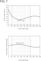
- FIG. 7 shows a graph representing the distribution of the outer diameter of the diffuser passage 8 in the circumferential direction and a graph representing the distribution of the inclination angle ⁇ in this case.
- the inclination angle ⁇ has a minimum value in the range of the central angle ⁇ of 30° to 210°.
- the outer diameter of the diffuser passage 8 has a local maximum value in the range of the central angle ⁇ of 30° to 210°.
- a distance R (see FIG. 2 ) from the rotational axis L to the scroll center O s of the scroll passage 5 is decreased locally in the circumferential direction. More specifically, the distribution of the distance R in the circumferential direction has a local minimum value or a minimum value in the range of the central angle ⁇ of 30° to 210°. Referring to FIG. 5 , the cross-section of the scroll passage 5 is located on a more radially inner side at a portion where the distance R is locally decreased than at other portions, although the outlet of the diffuser passage 8 is at the same position. Thus, since the inclination of the tangential direction A of the portion 5a1 becomes closer to the horizontal direction, the inclination angle ⁇ is decreased.
- FIG. 8 shows a graph representing the distribution of the distance R in the circumferential direction and a graph representing the distribution of inclination angle ⁇ in this case.
- the inclination angle ⁇ has a minimum value in the range of the central angle ⁇ of 30° to 210°.
- the distance R has a local minimum value in the range of the central angle ⁇ of 30° to 210°.
- locally increasing the outer diameter of the diffuser passage 8 (see FIG. 1 ) in the circumferential direction is combined with locally decreasing the distance R (see FIG. 2 ) from the rotational axis L to the scroll center O s of the scroll passage 5 in the circumferential direction. If one of these measures is adopted alone, the outer diameter of the diffuser passage 8 may be excessively locally increased, or the distance R may be excessively locally decreased. In this case, manufacturing may be difficult, or the flow f the compressed air may be adversely affected. However, by combining them, it is possible to moderate the local changes in the outer diameter of the diffuser passage 8 and the distance R.
- the second passage wall 7b includes the flat end surface 22 connected to the flat inner wall surface 21 at right angle, the convex inner wall surface 23 connected to the end surface 22 and curved convexly with respect to the scroll passage 5, and the concave inner wall surface 24 connected to the convex inner wall surface 23 and curved concavely with respect to the scroll passage 5.
- the end surface 22 may not be perpendicular to the flat inner wall surface 21.
- the end surface 22 may be not flat but curved.
- the convex inner wall surface 23 may be eliminated, and the concave inner wall surface 24 and the end surface may be connected to each other.
- FIG. 9 shows an example in which the concave inner wall surface 24 includes two concave inner wall surfaces.
- the two concave inner wall surfaces may form a first concave arc portion 241 and a second concave arc portion 242, respectively.
- the second concave arc portion 242 has a radially inner edge 242a and a radially outer edge 242b, and the edge 242a is connected to the first concave arc portion 241, and the edge 242b is connected to the convex arc portion 23a.
- the inclination angle ⁇ is an angle between the tangential direction A of the radially outer edge of the radially outermost concave arc portion, i.e. the tangential direction A of the radially outer edge 242b of the second concave arc portion 242, and the direction ⁇ perpendicular to the rotational axis L.
- the distribution of the inclination angle ⁇ has a local minimum value or a minimum value in the range of the central angle ⁇ of 30° to 210°, according to the invention it has a minimum value in the range of the central angle ⁇ of 30° to 120° (see FIG. 6 ).
- the flow passage area of the scroll passage 5 gradually decreases from the outlet toward the tongue 4a. Due to this shape of the scroll passage 5, the inclination angle ⁇ (see FIG. 5 ) of the concave arc portion 24a (see FIG. 5 ) tends to increase as it approximates to the tongue 4a.
- the scroll passage 5 is formed without considering the size of the inclination angle ⁇ , the inclination angle ⁇ tends to increase in the range of the central angle ⁇ of 30° to 120°.
- the inclination angle ⁇ is decreased in this range.
- interference between the swirl flow f 2 and the flow f 3 of the compressed fluid discharged from the diffuser passage 8 is reduced, and the occurrence of separation in the scroll passage 8 is reduced.
- the diffuser passage is generally formed by cutting, in the above embodiments, since the flat inner wall surface 21 defining the diffuser passage 8 is flat and perpendicular to the rotational axis L, it is easy to process the diffuser passage 8.
Landscapes
- Engineering & Computer Science (AREA)
- Mechanical Engineering (AREA)
- General Engineering & Computer Science (AREA)
- Chemical & Material Sciences (AREA)
- Combustion & Propulsion (AREA)
- Structures Of Non-Positive Displacement Pumps (AREA)
- Supercharger (AREA)
Description
- The present disclosure relates to a centrifugal compressor and a turbocharger including the centrifugal compressor.
- In recent year, it is desired to enlarge the operating region of centrifugal compressors. For instance, as automobile engines require to improve fuel efficiency and acceleration performance in a low speed region, turbochargers require to improve the efficiency in a low speed and low flow rate operating point. Such an operating region is a region where a centrifugal compressor of a turbocharger operates in a stall condition. In this region, large separation is observed in a scroll passage.
Patent Document 1 describes that separation occurs due to recirculation flow from the scroll end to the scroll start in the scroll passage.Patent document 2 describes a centrifugal compressor according to the preamble ofclaim 1. -
- Patent Document 1:
WO2017/109949A - Patent document 2:
JP 2010 216378 A - However, as a result of intensive studies by the present inventors, they have found that separation occurs by a factor other than the recirculation flow described in
Patent Document 1. More specifically, compressed air discharged from a diffuser passage in the vicinity of a tongue of a scroll part forming the scroll passage swirls and flows through the scroll passage along the inner wall surface of the scroll passage. Such a swirl flow having made one round along the inner wall surface of the scroll passage interferes with compressed air discharged from the diffuser passage. This is one of factors of separation in the scroll passage. - In view of the above, an object of at least one embodiment of the present disclosure is to provide a centrifugal compressor and a turbocharger including the centrifugal compressor whereby it is possible to improve the efficiency in a low flow rate operating point.
-
- (1) A centrifugal compressor according to the invention is according to
claim 1. Hence, it comprises: an impeller and a housing. The housing includes: a scroll part having a scroll passage of a spiral shape formed on an outer peripheral side of the impeller; and a diffuser part including a pair of passage walls spaced from each other in an extension direction of a rotational axis of the impeller and forming a diffuser passage, communicating with the scroll passage along a circumferential direction of the scroll passage on a radially inner side of the scroll part, between the pair of passage walls. - With the above configuration (1), as a swirl flow swirling and flowing through the scroll passage along the inner wall surface of the scroll passage circulates one round along the inner wall surface of the scroll passage, the angle between the direction of the swirl flow and the flow direction of a compressed fluid discharged from the diffuser passage decreases. Thus, interference between the swirl flow and the flow of the compressed fluid discharged from the diffuser passage is reduced, and the occurrence of separation in the scroll passage is reduced. As a result, it is possible to improve the efficiency of the centrifugal compressor in a low flow rate operating point.
- The flow passage area of the scroll passage gradually decreases from the outlet toward the tongue. Due to this shape of the scroll passage, the inclination angle of the concave arc portion tends to increase as it approximates to the tongue. With the above configuration, by forming the scroll passage such that the inclination angle has a local minimum value or a minimum value in the range of the central angle of 30° to 120° where the inclination angle tends to increase if the scroll passage is formed without considering the size of the inclination angle, it is possible to decrease the inclination angle in the range of the central angle of 30° to 210°. Thus, interference between the swirl flow and the flow of the compressed fluid discharged from the diffuser passage is reduced, and the occurrence of separation in the scroll passage is reduced. As a result, it is possible to improve the efficiency of the centrifugal compressor in a low flow rate operating point.
- (3) In some embodiments, in the above configuration (1), the second passage wall includes: a flat inner wall surface which defines the diffuser passage and is flat and perpendicular to the rotational axis; a convex inner wall surface defining the scroll passage and curved convexly with respect to the scroll passage; at least one concave inner wall surface defining the scroll passage and forming the at least one concave arc portion in the cross-section of the housing formed by the plane that includes the rotational axis, the at least one concave inner wall surface including a radially outermost concave inner wall surface located outermost in the radial direction of the impeller and connected to the convex arc portion; and an end surface connecting the flat inner surface and the convex inner wall surface at an outermost portion of the flat inner surface in the radial direction of the impeller.
- With the above configuration (3), in addition to that it is possible to reduce interference between the swirl flow and the flow of the compressed fluid discharged from the diffuser passage and reduce the occurrence of separation in the scroll passage, since the inner wall defining the diffuser passage is flat and perpendicular to the rotational axis, it is possible to easily perform processing of the diffuser passage.
- (4) In some embodiments, in any one of the above configurations (1) and (3), an outer diameter of the diffuser passage about the rotational axis has a distribution in a circumferential direction of the diffuser passage, and the distribution of the outer diameter of the diffuser passage has a local maximum value or a maximum value in a range of the central angle of 30° to 210°.
- With the above configuration (4), since the inclination angle of the concave arc portion has a minimum value in the range of the central angle of 30° to 120°, interference between the swirl flow and the flow of the compressed fluid discharged from the diffuser passage is reduced, and the occurrence of separation in the scroll passage is reduced. As a result, it is possible to improve the efficiency of the centrifugal compressor in a low flow rate operating point.
- (5) In some embodiments, in any one of the above configurations (1), (3) and (4), a distance from the rotational axis to the scroll center of the scroll passage has a distribution in a circumferential direction of the diffuser passage, and the distribution of the distance has a local minimum value or a minimum value in a range of the central angle of 30° to 210°.
- With the above configuration (5), since the inclination angle of the concave arc portion has a minimum value in the range of the central angle of 30° to 120°, interference between the swirl flow and the flow of the compressed fluid discharged from the diffuser passage is reduced, and the occurrence of separation in the scroll passage is reduced. As a result, it is possible to improve the efficiency of the centrifugal compressor in a low flow rate operating point.
- (6) A turbocharger according to at least one embodiment of the present disclosure comprises: the centrifugal compressor described in any one of the above (1) and (3) to (5).
- With the above configuration (6), since the occurrence of separation in the scroll passage is reduced, it is possible to improve the efficiency of the turbocharger in a low speed and low flow rate operating point.
- According to at least one embodiment of the present disclosure, as a swirl flow swirling and flowing through the scroll passage along the inner wall surface of the scroll passage circulates one round along the inner wall surface of the scroll passage, the angle between the direction of the swirl flow and the flow direction of a compressed fluid discharged from the diffuser passage decreases. Thus, interference between the swirl flow and the flow of the compressed fluid discharged from the diffuser passage is reduced, and the occurrence of separation in the scroll passage is reduced. As a result, it is possible to improve the efficiency of the centrifugal compressor in a low flow rate operating point.
-
-
FIG. 1 is a schematic diagram of an exemplary cross-section perpendicular to the rotational axis of a centrifugal compressor according to an embodiment of the present disclosure. -
FIG. 2 is a partial cross-sectional view of a housing of a centrifugal compressor in a plan view including the rotational axis of the centrifugal compressor according to an embodiment of the present disclosure. -
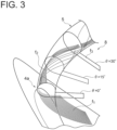
FIG. 3 is a streamline diagram showing compressed air discharged from a diffuser passage and swirling along an inner wall surface of a scroll passage in a centrifugal compressor according to an embodiment of the present disclosure. -
FIG. 4 is a schematic diagram for describing the principle of interference between swirl flow and compressed air discharged from a diffuser passage in a scroll passage. -
FIG. 5 is a schematic cross-sectional view showing the cross-sectional shape of a scroll passage of a centrifugal compressor according to an embodiment of the present disclosure. -
FIG. 6 is a graph representing the distribution of inclination angle α in a centrifugal compressor according to an embodiment of the present disclosure. -
FIG. 7 is graphs representing the distribution of the outer diameter of a diffuser passage and the distribution of inclination angle α in a centrifugal compressor according to an embodiment of the present disclosure. -
FIG. 8 is graphs representing the distribution of the distance between the rotational axis and the scroll center and the distribution of inclination angle a in a centrifugal compressor according to an embodiment that is not part of the invention. -
FIG. 9 is an enlarged partial cross-sectional view of a second passage wall of a centrifugal compressor according to an embodiment of the present disclosure. - Embodiments of the present invention will now be described in detail with reference to the accompanying drawings. However, the scope of the present invention is not limited to the following embodiments. It is intended that dimensions, materials, shapes, relative positions and the like of components described in the embodiments shall be interpreted as illustrative only and not intended to limit the scope of the present invention.
- A centrifugal compressor according to an embodiment of the present disclosure will be described by taking a centrifugal compressor of a turbocharger as an example. However, the centrifugal compressor in the present disclosure is not limited to a centrifugal compressor of a turbocharger, and may be any centrifugal compressor which operates alone. Although a fluid to be compressed by the compressor is air in the following description, the fluid may be replaced by any other fluid.
- As shown in
FIG. 1 , thecentrifugal compressor 1 includes ahousing 2 and animpeller 3 rotatably disposed around the rotational axis L within thehousing 2. As shown inFIG. 2 , thehousing 2 includes ascroll part 4 having ascroll passage 5 of spiral shape formed on the outer peripheral side of theimpeller 3, adiffuser part 6 having a pair ofpassage walls 7, i.e., afirst passage wall 7a and asecond passage wall 7b, spaced from each other in an extension direction of the rotational axis L, and anair inlet part 9 of cylindrical shape. Thesecond passage wall 7b is positioned closer to the scroll center Os of thescroll passage 5 than thefirst passage wall 7a is in the extension direction of the rotational axis L. Between thefirst passage wall 7a and thesecond passage wall 7b, adiffuser passage 8 is formed and communicates with thescroll passage 5 along the circumferential direction of thescroll passage 5 on the radially inner side of theimpeller 3. - Air flowing into the
centrifugal compressor 1 through theair inlet part 9 is compressed by theimpeller 3 into compressed air. The compressed air flows through thediffuser passage 8 into thescroll passage 5 and then passes through thescroll passage 5 and is discharged from thecentrifugal compressor 1. - When the flow rate of air into the
centrifugal compressor 1 is small since, for instance, the turbocharger operates at low speed, thecentrifugal compressor 1 operates in a stall condition, resulting in a decrease in efficiency. In such an operating region, large separation is observed in thescroll passage 5. The present inventors have found one of factors that cause this separation as a result of intensive studies. The mechanism of separation due to this factor will now be described. - As shown in
FIG. 1 , the circumferential position in thescroll passage 5 from atongue 4a of the scroll part 4 (seeFIG. 2 ) to the outlet of thescroll passage 5 is represented by a central angle θ about the rotational axis L by using thetongue 4a as a reference. Accordingly, the central angle θ representing the circumferential position of thetongue 4a is 0°. - As shown in
FIG. 3 , the flow f1 of compressed air discharged from thediffuser passage 8 in the vicinity of thetongue 4a swirls and flows through thescroll passage 5 along the inner wall surface of thescroll passage 5. When this swirl flow f2 of the compressed air circulates one round along the inner wall surface of the scroll passage 5 (inFIG. 3 , at a position where the central angle θ is 30° approximately), the swirl flow f2 interferes with compressed air f3 discharged from thediffuser passage 8. This interference is one of factors of separation in thescroll passage 5. - As shown in part (a) of
FIG. 4 , in a cross-section of the housing 2 (seeFIG. 2 ) including the rotational axis L, as an inclination angle α between a tangential direction A of a portion 5a1 of theinner wall surface 5a of thescroll passage 5 connected to thesecond passage wall 7b and a direction B perpendicular to the rotational axis L increases, i.e., as the inclination angle α approximates to 90°, the angle β between the swirl flow f2 of the compressed air flowing along theinner wall surface 5a of thescroll passage 5 and the flow f3 of the compressed air discharged from thediffuser passage 8 increases. Thus, the swirl flow f2 interferes with and blocks the flow f3 of the compressed air that is about to flow from thediffuser passage 8 into thescroll passage 5, so that separation is caused at the interference portion. - Therefore, to suppress the occurrence of interference, the cross-sectional shape of the
scroll passage 5 needs to have a reduced inclination angle α.FIG. 5 shows an exemplary cross-sectional shape of thescroll passage 5 with a reduced inclination angle α. Thesecond passage wall 7b includes a flatinner wall surface 21 which defines thediffuser passage 8 and is flat and perpendicular to the rotational axis L, aflat end surface 22 connected to the radially outermost portion of the flatinner wall surface 21 at right angle, a convexinner wall surface 23 connected to theend surface 22 and curved convexly with respect to thescroll passage 5, and a concaveinner wall surface 24 connected to the convexinner wall surface 23 and curved concavely with respect to thescroll passage 5. Here, theinner wall surface 5a of thescroll passage 5 is divided into a radially inner portion 5a2 and a radially outer portion 5a3 by a virtual line L' passing through the scroll center Os and parallel to the rotational axis L. Theend surface 22, the convexinner wall surface 23, and the concaveinner wall surface 24 are a part of the portion 5a2 of theinner wall surface 5a. - Curving convexly with respect to the
scroll passage 5 means that the curvature center of aconvex arc portion 23a forming the convexinner wall surface 23 is positioned outside thescroll passage 5 in the cross-section of the housing 2 (seeFIG. 2 ) including the rotational axis L, and curving concavely with respect to thescroll passage 5 means that the curvature center of aconcave arc portion 24a forming the concaveinner wall surface 24 is positioned inside thescroll passage 5 in the cross-section of the housing 2 (seeFIG. 2 ) including the rotational axis L. - In the cross-section of the
housing 2 including the rotational axis L, as the inclination angle α between the tangential direction A of a radially outer edge 24a1 of theconcave arc portion 24a and the direction B perpendicular to the rotational axis L decreases, the angle β between the swirl flow f2 and the flow f3 of the compressed air that is about to flow from thediffuser passage 8 to thescroll passage 5 decreases. Thus, since interference between the swirl flow f2 and the flow f3 of the compressed fluid is reduced, the occurrence of separation is reduced. Accordingly, by making the cross-sectional shape of thescroll passage 5 such that the inclination angle α is small at the portion where interference can occur, it is possible to reduce the occurrence of separation. - Further, the present inventors have found that separation is likely to occur in a range of the central angle θ of 30° to 210° by CFD analysis. The reason is that when stable swirl flow is generated in the
scroll passage 5, the swirl flow in thescroll passage 5 and the flow of the compressed air discharged from thediffuser passage 8 gradually stop interfering with each other, and thus interference is mainly caused on the upstream side in thescroll passage 5. Accordingly, by making the cross-sectional shape of thescroll passage 5 such that the inclination angle α is small on the upstream side, it is possible to effectively reduce the occurrence of separation. - The cross-sectional shape of the
scroll passage 5 shown inFIG. 5 is the shape of one cross-section of the housing 2 (seeFIG. 2 ). Actually, the cross-sectional shape of thescroll passage 5 changes along the circumferential direction. Accordingly, the inclination angle α changes along the circumferential direction. That is, the inclination angle α is distributed along the circumferential direction of thescroll passage 5. According to the findings by the present invention, as shown inFIG. 6 , when the distribution of the inclination angle α has a minimum value in a range of the circumferential position of thescroll passage 5 where the central angle θ is 30° to 210°, it is possible to effectively reduce the occurrence of separation. The distribution of the inclination angle α may not have the minimum value in the above range, but may have a local minimum value in the range of the central angle θ of 30° to 210°. In other words, in a range of the central angle θ larger than 210°, the distribution of the inclination angle α may have a value smaller than the local minimum value. - Next, some embodiments of the housing 2 (see
FIG. 2 ) in which the distribution of the inclination angle α has a minimum value or a local minimum value in the range of the central angle θ of 30° to 210° will be described. - In an embodiment, the outer diameter of the diffuser passage 8 (see
FIG. 1 ) is increased locally in the circumferential direction. More specifically, the distribution of the outer diameter of thediffuser passage 8 in the circumferential direction has a local maximum value or a maximum value in the range of the central angle θ of 30° to 210°. Referring toFIG. 5 , theend surface 22 of thesecond passage wall 7b is located on a more radially outer side at a portion where the outer diameter of thediffuser passage 8 is locally increased than at other portions. Thus, since the width of the concaveinner wall surface 24 in the radial direction is increased, the inclination of the tangential direction A of the portion 5a1 becomes closer to the horizontal direction, and the inclination angle α is decreased. -
FIG. 7 shows a graph representing the distribution of the outer diameter of thediffuser passage 8 in the circumferential direction and a graph representing the distribution of the inclination angle α in this case. When it is configured such that the outer diameter of thediffuser passage 8 has a maximum value in the range of the central angle θ of 30° to 210°, the inclination angle α has a minimum value in the range of the central angle θ of 30° to 210°. In a case where the inclination angle α does not have a minimum value but has a local minimum value in this range, it is configured such that the outer diameter of thediffuser passage 8 has a local maximum value in the range of the central angle θ of 30° to 210°. - Alternatively, in some embodiments, a distance R (see
FIG. 2 ) from the rotational axis L to the scroll center Os of thescroll passage 5 is decreased locally in the circumferential direction. More specifically, the distribution of the distance R in the circumferential direction has a local minimum value or a minimum value in the range of the central angle θ of 30° to 210°. Referring toFIG. 5 , the cross-section of thescroll passage 5 is located on a more radially inner side at a portion where the distance R is locally decreased than at other portions, although the outlet of thediffuser passage 8 is at the same position. Thus, since the inclination of the tangential direction A of the portion 5a1 becomes closer to the horizontal direction, the inclination angle α is decreased. -
FIG. 8 shows a graph representing the distribution of the distance R in the circumferential direction and a graph representing the distribution of inclination angle α in this case. When it is configured such that the distance R has a minimum value in the range of the central angle θ of 30° to 210°, the inclination angle α has a minimum value in the range of the central angle θ of 30° to 210°. In a case where the inclination angle α does not have a minimum value but has a local minimum value in this range, it is configured such that the distance R has a local minimum value in the range of the central angle θ of 30° to 210°. - Alternatively, in some embodiments, locally increasing the outer diameter of the diffuser passage 8 (see
FIG. 1 ) in the circumferential direction is combined with locally decreasing the distance R (seeFIG. 2 ) from the rotational axis L to the scroll center Os of thescroll passage 5 in the circumferential direction. If one of these measures is adopted alone, the outer diameter of thediffuser passage 8 may be excessively locally increased, or the distance R may be excessively locally decreased. In this case, manufacturing may be difficult, or the flow f the compressed air may be adversely affected. However, by combining them, it is possible to moderate the local changes in the outer diameter of thediffuser passage 8 and the distance R. - As described above, as the swirl flow f2 swirling and flowing through the
scroll passage 5 along theinner wall surface 5a of thescroll passage 5 circulates one round along theinner wall surface 5a of thescroll passage 5, the angle β between the direction of the swirl flow f2 and the direction of the flow f3 of the compressed fluid discharged from thediffuser passage 8 decreases. Thus, interference between the swirl flow f2 and the flow f3 of the compressed fluid discharged from thediffuser passage 8 is reduced, and the occurrence of separation in thescroll passage 5 is reduced. As a result, it is possible to improve the efficiency of thecentrifugal compressor 1 in a low flow rate operating point. - In the above embodiments, the
second passage wall 7b includes theflat end surface 22 connected to the flatinner wall surface 21 at right angle, the convexinner wall surface 23 connected to theend surface 22 and curved convexly with respect to thescroll passage 5, and the concaveinner wall surface 24 connected to the convexinner wall surface 23 and curved concavely with respect to thescroll passage 5. However, the present invention is not limited thereto. Theend surface 22 may not be perpendicular to the flatinner wall surface 21. Theend surface 22 may be not flat but curved. Further, the convexinner wall surface 23 may be eliminated, and the concaveinner wall surface 24 and the end surface may be connected to each other. - Further, two or more concave inner wall surfaces 24 may be included.
FIG. 9 shows an example in which the concaveinner wall surface 24 includes two concave inner wall surfaces. In the cross-section of the housing 2 (seeFIG. 2 ) including the rotational axis L, the two concave inner wall surfaces may form a firstconcave arc portion 241 and a secondconcave arc portion 242, respectively. The secondconcave arc portion 242 has a radiallyinner edge 242a and a radiallyouter edge 242b, and theedge 242a is connected to the firstconcave arc portion 241, and theedge 242b is connected to theconvex arc portion 23a. In this embodiment, the inclination angle α is an angle between the tangential direction A of the radially outer edge of the radially outermost concave arc portion, i.e. the tangential direction A of the radiallyouter edge 242b of the secondconcave arc portion 242, and the direction β perpendicular to the rotational axis L. - Although in the above embodiments, the distribution of the inclination angle α has a local minimum value or a minimum value in the range of the central angle θ of 30° to 210°, according to the invention it has a minimum value in the range of the central angle θ of 30° to 120° (see
FIG. 6 ). As shown inFIG. 1 , the flow passage area of thescroll passage 5 gradually decreases from the outlet toward thetongue 4a. Due to this shape of thescroll passage 5, the inclination angle α (seeFIG. 5 ) of theconcave arc portion 24a (seeFIG. 5 ) tends to increase as it approximates to thetongue 4a. If thescroll passage 5 is formed without considering the size of the inclination angle α, the inclination angle α tends to increase in the range of the central angle θ of 30° to 120°. However, by forming thescroll passage 5 such that the inclination angle α has a local minimum value or a minimum value in the range of the central angle θ of 30° to 120°, the inclination angle α is decreased in this range. Thus, interference between the swirl flow f2 and the flow f3 of the compressed fluid discharged from thediffuser passage 8 is reduced, and the occurrence of separation in thescroll passage 8 is reduced. As a result, it is possible to improve the efficiency of thecentrifugal compressor 1 in a low flow rate operating point. - Further, although the diffuser passage is generally formed by cutting, in the above embodiments, since the flat
inner wall surface 21 defining thediffuser passage 8 is flat and perpendicular to the rotational axis L, it is easy to process thediffuser passage 8. -
- 1
- Centrifugal compressor
- 2
- Housing
- 3
- Impeller
- 4
- Scroll part
- 4a
- Tongue
- 5
- Scroll passage
- 5a
- Inner wall surface (of scroll passage)
- 5a1
- Portion (of inner wall surface)
- 5a2
- Radially inner portion (of inner wall surface)
- 5a3
- Radially outer portion (of inner wall surface)
- 6
- Diffuser part
- 7
- Passage wall
- 7a
- First passage wall
- 7b
- Second passage wall
- 8
- Diffuser passage
- 9
- Air inlet part
- 21
- Flat inner wall surface
- 22
- End surface
- 23
- Convex inner wall surface
- 23a
- Convex arc portion
- 24
- Concave inner wall surface
- 24a
- Concave arc portion
- 24a1
- Edge (of concave arc portion)
- 241
- First concave arc portion
- 242
- Second concave arc portion
- 242a
- Edge (of second concave arc portion)
- 242b
- Edge (of second concave arc portion)
- A
- Tangential direction
- B
- Direction perpendicular to rotational axis
- L
- Rotational axis (of impeller)
- L'
- Virtual line
- Os
- Scroll center
- α
- Inclination angle
- β
- Angle
- θ
- Central angle
- f1
- Flow of compressed air discharged from diffuser passage in vicinity of tongue
- f2
- Swirl flow
- f3
- Flow of compressed air discharged from diffuser passage
Claims (5)
- A centrifugal compressor (1) comprising an impeller (3) and a housing (2),wherein the housing (2) includes:a scroll part (4) having a scroll passage (5) of a spiral shape formed on an outer peripheral side of the impeller (3); anda diffuser part (6) including a pair of passage walls (7) spaced from each other in an extension direction of a rotational axis (L) of the impeller (3), the diffuser part (6) forming a diffuser passage (8) between the pair of passage walls (7), the diffuser passage (8) communicating with the scroll passage (5) along a circumferential direction of the scroll passage (5) on a radially inner side of the scroll part (4),wherein the pair of passage walls (7) includes:a first passage wall (7a); anda second passage wall (7b) positioned closer to a scroll center (Os) of the scroll passage (5) than the first passage wall (7a) is to the scroll center (Os) in the extension direction of the rotational axis (L),wherein the second passage wall (7b) includes a radially inner portion (5a2) of an inner wall surface (5a) of the scroll passage (5), and the radially inner portion (5a2) of the inner wall surface (5a) included in the second passage wall (7b) forms at least one concave arc portion (24a) having a curvature center inside the scroll passage (5) in a cross-section of the housing (2) formed by a plane that includes the rotational axis (L),wherein the at least one concave arc portion (24a) includes a radially outermost concave arc portion located outermost in a radial direction of the impeller (3), and an inclination angle (α) between a tangential direction (A) of a radially outer edge (24a1) of the radially outermost concave arc portion and a direction perpendicular to the rotational axis (L) has a distribution along the circumferential direction of the scroll passage (5),characterised in that, when a circumferential position in the scroll passage (5) from a tongue (4a) of the scroll part (4) to an outlet of the scroll passage (5) is represented by a central angle (θ) about the rotational axis (L) by using the tongue (4a) as a reference, the distribution of the inclination angle (α) has a minimum value in a range of the central angle (θ) of 30° to 120°.
- The centrifugal compressor (1) according to claim 1,
wherein the second passage wall (7b) includes:a flat inner wall surface (21) which defines the diffuser passage (8) and is flat and perpendicular to the rotational axis (L);a convex inner wall surface (23) defining the scroll passage (5) and curved convexly with respect to the scroll passage (5);at least one concave inner wall surface (24) defining the scroll passage (5) and forming the at least one concave arc portion (24a) in the cross-section of the housing (2) formed by the plane that includes the rotational axis (L), the at least one concave inner wall surface (24) including a radially outermost concave inner wall surface located outermost in the radial direction of the impeller (3), the radially outermost concave inner wall surface being connected to the convex inner wall surface (23); andan end surface (22) connecting the flat inner surface and the convex inner wall surface (23) at an outermost portion of the flat inner surface in the radial direction of the impeller (3). - The centrifugal compressor (1) according to any one of claims 1 or 2,
wherein an outer diameter of the diffuser passage (8) about the rotational axis (L) has a distribution in a circumferential direction of the diffuser passage (8), and the distribution of the outer diameter of the diffuser passage (8) has a local maximum value or a maximum value in a range of the central angle (θ) of 30° to 210°. - The centrifugal compressor according to any one of claims 1 to 3, wherein a distance (R) from the rotational axis (L) to the scroll center (Os) of the scroll passage (5) has a distribution in a circumferential direction of the diffuser passage (8), and the distribution of the distance (R) has a local minimum value or a minimum value in a range of the central angle (θ) of 30° to 210°.
- A turbocharger comprising the centrifugal compressor (1) according to any one of claims 1 to 4.
Applications Claiming Priority (1)
| Application Number | Priority Date | Filing Date | Title |
|---|---|---|---|
| PCT/JP2017/039909 WO2019087385A1 (en) | 2017-11-06 | 2017-11-06 | Centrifugal compressor and turbocharger comprising said centrifugal compressor |
Publications (3)
| Publication Number | Publication Date |
|---|---|
| EP3708848A1 EP3708848A1 (en) | 2020-09-16 |
| EP3708848A4 EP3708848A4 (en) | 2021-07-07 |
| EP3708848B1 true EP3708848B1 (en) | 2025-05-07 |
Family
ID=66331524
Family Applications (1)
| Application Number | Title | Priority Date | Filing Date |
|---|---|---|---|
| EP17930425.8A Active EP3708848B1 (en) | 2017-11-06 | 2017-11-06 | Centrifugal compressor and turbocharger comprising said centrifugal compressor |
Country Status (5)
| Country | Link |
|---|---|
| US (1) | US11073164B2 (en) |
| EP (1) | EP3708848B1 (en) |
| JP (1) | JP6842564B2 (en) |
| CN (1) | CN110573748B (en) |
| WO (1) | WO2019087385A1 (en) |
Families Citing this family (7)
| Publication number | Priority date | Publication date | Assignee | Title |
|---|---|---|---|---|
| DE112019007061T5 (en) | 2019-05-30 | 2021-12-16 | Mitsubishi Heavy Industries Engine & Turbocharger, Ltd. | CENTRIFUGAL COMPRESSOR AND TURBOCHARGER |
| US12031546B2 (en) * | 2020-04-17 | 2024-07-09 | Mitsubishi Heavy Industries Engine & Turbocharger, Ltd. | Scroll casing and centrifugal compressor |
| CN115698516B (en) * | 2020-05-21 | 2025-06-27 | 三菱重工发动机和增压器株式会社 | Volute and centrifugal compressors |
| DE112021003609T5 (en) * | 2020-12-09 | 2023-04-27 | Ihi Corporation | centrifugal compressor and turbocharger |
| CN114857088B (en) * | 2022-05-30 | 2024-06-25 | 杭州老板电器股份有限公司 | Fume exhauster |
| US20240355437A1 (en) * | 2023-04-21 | 2024-10-24 | Matrixcare, Inc. | Machine learning-based summarization and evaluation of clinical data |
| CN120281415A (en) * | 2024-01-08 | 2025-07-08 | 宁波环球广电科技有限公司 | Parameter adjustment method and system |
Family Cites Families (10)
| Publication number | Priority date | Publication date | Assignee | Title |
|---|---|---|---|---|
| JP2005188337A (en) * | 2003-12-25 | 2005-07-14 | Toyota Motor Corp | Supercharging compressor with working fluid return path |
| DE102007034236A1 (en) | 2007-07-23 | 2009-02-05 | Continental Automotive Gmbh | Centrifugal compressor with a diffuser for use with a turbocharger |
| JP5204016B2 (en) * | 2009-03-17 | 2013-06-05 | 株式会社神戸製鋼所 | Turbo compressor |
| JP5517914B2 (en) | 2010-12-27 | 2014-06-11 | 三菱重工業株式会社 | Centrifugal compressor scroll structure |
| JP5479316B2 (en) * | 2010-12-28 | 2014-04-23 | 三菱重工業株式会社 | Centrifugal compressor scroll structure |
| JP5517981B2 (en) * | 2011-03-17 | 2014-06-11 | 三菱重工業株式会社 | Centrifugal compressor scroll structure |
| JP5439423B2 (en) * | 2011-03-25 | 2014-03-12 | 三菱重工業株式会社 | Scroll shape of centrifugal compressor |
| JP6062888B2 (en) | 2014-07-07 | 2017-01-18 | トヨタ自動車株式会社 | Turbocharger |
| JP6551541B2 (en) * | 2015-12-10 | 2019-07-31 | 株式会社Ihi | Discharge part structure of centrifugal compressor |
| WO2017109949A1 (en) | 2015-12-25 | 2017-06-29 | 三菱重工業株式会社 | Centrifugal compressor and turbocharger |
-
2017
- 2017-11-06 US US16/605,454 patent/US11073164B2/en active Active
- 2017-11-06 CN CN201780090061.3A patent/CN110573748B/en active Active
- 2017-11-06 JP JP2019550120A patent/JP6842564B2/en active Active
- 2017-11-06 WO PCT/JP2017/039909 patent/WO2019087385A1/en not_active Ceased
- 2017-11-06 EP EP17930425.8A patent/EP3708848B1/en active Active
Also Published As
| Publication number | Publication date |
|---|---|
| JPWO2019087385A1 (en) | 2020-04-23 |
| WO2019087385A1 (en) | 2019-05-09 |
| EP3708848A1 (en) | 2020-09-16 |
| CN110573748B (en) | 2021-06-01 |
| US20210123456A1 (en) | 2021-04-29 |
| CN110573748A (en) | 2019-12-13 |
| EP3708848A4 (en) | 2021-07-07 |
| US11073164B2 (en) | 2021-07-27 |
| JP6842564B2 (en) | 2021-03-17 |
Similar Documents
| Publication | Publication Date | Title |
|---|---|---|
| EP3708848B1 (en) | Centrifugal compressor and turbocharger comprising said centrifugal compressor | |
| JP7082948B2 (en) | Centrifugal compressor, turbocharger | |
| CN108700089B (en) | Centrifugal compressor and turbocharger | |
| US10788045B2 (en) | Discharge section structure for centrifugal compressor | |
| US12460562B2 (en) | Mixed flow turbine and turbocharger | |
| CN107614885B (en) | Volute and centrifugal compressor | |
| CN115380169B (en) | Impeller and centrifugal compressor | |
| CN111911455A (en) | Impeller of centrifugal compressor, centrifugal compressor and turbocharger | |
| US11209015B2 (en) | Centrifugal compressor | |
| CN108700090A (en) | Compressor is vortexed and centrifugal compressor | |
| CN110582648B (en) | Centrifugal compressor and turbocharger having the same | |
| US11965524B2 (en) | Centrifugal compressor and turbocharger | |
| US11905969B2 (en) | Scroll structure of centrifugal compressor and centrifugal compressor | |
| US20250198310A1 (en) | Turbine | |
| JP7232332B2 (en) | Scroll structure of centrifugal compressor and centrifugal compressor | |
| JP2025094607A (en) | Axial Flow Turbine | |
| WO2020039919A1 (en) | Centrifugal compressor | |
| JP2012057489A (en) | Diffuser of centrifugal compressor, and centrifugal compressor equipped with the diffuser | |
| JPWO2019193683A1 (en) | Centrifugal compressor and turbocharger equipped with this centrifugal compressor |
Legal Events
| Date | Code | Title | Description |
|---|---|---|---|
| STAA | Information on the status of an ep patent application or granted ep patent |
Free format text: STATUS: THE INTERNATIONAL PUBLICATION HAS BEEN MADE |
|
| PUAI | Public reference made under article 153(3) epc to a published international application that has entered the european phase |
Free format text: ORIGINAL CODE: 0009012 |
|
| STAA | Information on the status of an ep patent application or granted ep patent |
Free format text: STATUS: REQUEST FOR EXAMINATION WAS MADE |
|
| 17P | Request for examination filed |
Effective date: 20191030 |
|
| AK | Designated contracting states |
Kind code of ref document: A1 Designated state(s): AL AT BE BG CH CY CZ DE DK EE ES FI FR GB GR HR HU IE IS IT LI LT LU LV MC MK MT NL NO PL PT RO RS SE SI SK SM TR |
|
| AX | Request for extension of the european patent |
Extension state: BA ME |
|
| DAV | Request for validation of the european patent (deleted) | ||
| DAX | Request for extension of the european patent (deleted) | ||
| A4 | Supplementary search report drawn up and despatched |
Effective date: 20210604 |
|
| RIC1 | Information provided on ipc code assigned before grant |
Ipc: F04D 29/44 20060101AFI20210528BHEP Ipc: F02B 39/00 20060101ALI20210528BHEP Ipc: F04D 29/42 20060101ALI20210528BHEP |
|
| STAA | Information on the status of an ep patent application or granted ep patent |
Free format text: STATUS: EXAMINATION IS IN PROGRESS |
|
| 17Q | First examination report despatched |
Effective date: 20230324 |
|
| GRAP | Despatch of communication of intention to grant a patent |
Free format text: ORIGINAL CODE: EPIDOSNIGR1 |
|
| STAA | Information on the status of an ep patent application or granted ep patent |
Free format text: STATUS: GRANT OF PATENT IS INTENDED |
|
| INTG | Intention to grant announced |
Effective date: 20241212 |
|
| GRAS | Grant fee paid |
Free format text: ORIGINAL CODE: EPIDOSNIGR3 |
|
| GRAA | (expected) grant |
Free format text: ORIGINAL CODE: 0009210 |
|
| STAA | Information on the status of an ep patent application or granted ep patent |
Free format text: STATUS: THE PATENT HAS BEEN GRANTED |
|
| AK | Designated contracting states |
Kind code of ref document: B1 Designated state(s): AL AT BE BG CH CY CZ DE DK EE ES FI FR GB GR HR HU IE IS IT LI LT LU LV MC MK MT NL NO PL PT RO RS SE SI SK SM TR |
|
| REG | Reference to a national code |
Ref country code: GB Ref legal event code: FG4D |
|
| REG | Reference to a national code |
Ref country code: CH Ref legal event code: EP |
|
| REG | Reference to a national code |
Ref country code: DE Ref legal event code: R096 Ref document number: 602017089399 Country of ref document: DE |
|
| REG | Reference to a national code |
Ref country code: IE Ref legal event code: FG4D |
|
| REG | Reference to a national code |
Ref country code: NL Ref legal event code: MP Effective date: 20250507 |
|
| PG25 | Lapsed in a contracting state [announced via postgrant information from national office to epo] |
Ref country code: ES Free format text: LAPSE BECAUSE OF FAILURE TO SUBMIT A TRANSLATION OF THE DESCRIPTION OR TO PAY THE FEE WITHIN THE PRESCRIBED TIME-LIMIT Effective date: 20250507 Ref country code: FI Free format text: LAPSE BECAUSE OF FAILURE TO SUBMIT A TRANSLATION OF THE DESCRIPTION OR TO PAY THE FEE WITHIN THE PRESCRIBED TIME-LIMIT Effective date: 20250507 Ref country code: PT Free format text: LAPSE BECAUSE OF FAILURE TO SUBMIT A TRANSLATION OF THE DESCRIPTION OR TO PAY THE FEE WITHIN THE PRESCRIBED TIME-LIMIT Effective date: 20250908 |
|
| REG | Reference to a national code |
Ref country code: LT Ref legal event code: MG9D |
|
| PG25 | Lapsed in a contracting state [announced via postgrant information from national office to epo] |
Ref country code: GR Free format text: LAPSE BECAUSE OF FAILURE TO SUBMIT A TRANSLATION OF THE DESCRIPTION OR TO PAY THE FEE WITHIN THE PRESCRIBED TIME-LIMIT Effective date: 20250808 Ref country code: NO Free format text: LAPSE BECAUSE OF FAILURE TO SUBMIT A TRANSLATION OF THE DESCRIPTION OR TO PAY THE FEE WITHIN THE PRESCRIBED TIME-LIMIT Effective date: 20250807 |
|
| PG25 | Lapsed in a contracting state [announced via postgrant information from national office to epo] |
Ref country code: PL Free format text: LAPSE BECAUSE OF FAILURE TO SUBMIT A TRANSLATION OF THE DESCRIPTION OR TO PAY THE FEE WITHIN THE PRESCRIBED TIME-LIMIT Effective date: 20250507 Ref country code: NL Free format text: LAPSE BECAUSE OF FAILURE TO SUBMIT A TRANSLATION OF THE DESCRIPTION OR TO PAY THE FEE WITHIN THE PRESCRIBED TIME-LIMIT Effective date: 20250507 |
|
| REG | Reference to a national code |
Ref country code: AT Ref legal event code: MK05 Ref document number: 1792735 Country of ref document: AT Kind code of ref document: T Effective date: 20250507 |
|
| PG25 | Lapsed in a contracting state [announced via postgrant information from national office to epo] |
Ref country code: BG Free format text: LAPSE BECAUSE OF FAILURE TO SUBMIT A TRANSLATION OF THE DESCRIPTION OR TO PAY THE FEE WITHIN THE PRESCRIBED TIME-LIMIT Effective date: 20250507 |
|
| PG25 | Lapsed in a contracting state [announced via postgrant information from national office to epo] |
Ref country code: HR Free format text: LAPSE BECAUSE OF FAILURE TO SUBMIT A TRANSLATION OF THE DESCRIPTION OR TO PAY THE FEE WITHIN THE PRESCRIBED TIME-LIMIT Effective date: 20250507 |
|
| PG25 | Lapsed in a contracting state [announced via postgrant information from national office to epo] |
Ref country code: AT Free format text: LAPSE BECAUSE OF FAILURE TO SUBMIT A TRANSLATION OF THE DESCRIPTION OR TO PAY THE FEE WITHIN THE PRESCRIBED TIME-LIMIT Effective date: 20250507 |
|
| PG25 | Lapsed in a contracting state [announced via postgrant information from national office to epo] |
Ref country code: RS Free format text: LAPSE BECAUSE OF FAILURE TO SUBMIT A TRANSLATION OF THE DESCRIPTION OR TO PAY THE FEE WITHIN THE PRESCRIBED TIME-LIMIT Effective date: 20250807 |
|
| PG25 | Lapsed in a contracting state [announced via postgrant information from national office to epo] |
Ref country code: IS Free format text: LAPSE BECAUSE OF FAILURE TO SUBMIT A TRANSLATION OF THE DESCRIPTION OR TO PAY THE FEE WITHIN THE PRESCRIBED TIME-LIMIT Effective date: 20250907 |
|
| PG25 | Lapsed in a contracting state [announced via postgrant information from national office to epo] |
Ref country code: LV Free format text: LAPSE BECAUSE OF FAILURE TO SUBMIT A TRANSLATION OF THE DESCRIPTION OR TO PAY THE FEE WITHIN THE PRESCRIBED TIME-LIMIT Effective date: 20250507 |
|
| PGFP | Annual fee paid to national office [announced via postgrant information from national office to epo] |
Ref country code: DE Payment date: 20250930 Year of fee payment: 9 |
|
| PG25 | Lapsed in a contracting state [announced via postgrant information from national office to epo] |
Ref country code: SM Free format text: LAPSE BECAUSE OF FAILURE TO SUBMIT A TRANSLATION OF THE DESCRIPTION OR TO PAY THE FEE WITHIN THE PRESCRIBED TIME-LIMIT Effective date: 20250507 Ref country code: DK Free format text: LAPSE BECAUSE OF FAILURE TO SUBMIT A TRANSLATION OF THE DESCRIPTION OR TO PAY THE FEE WITHIN THE PRESCRIBED TIME-LIMIT Effective date: 20250507 |
|
| PG25 | Lapsed in a contracting state [announced via postgrant information from national office to epo] |
Ref country code: CZ Free format text: LAPSE BECAUSE OF FAILURE TO SUBMIT A TRANSLATION OF THE DESCRIPTION OR TO PAY THE FEE WITHIN THE PRESCRIBED TIME-LIMIT Effective date: 20250507 |
|
| PG25 | Lapsed in a contracting state [announced via postgrant information from national office to epo] |
Ref country code: EE Free format text: LAPSE BECAUSE OF FAILURE TO SUBMIT A TRANSLATION OF THE DESCRIPTION OR TO PAY THE FEE WITHIN THE PRESCRIBED TIME-LIMIT Effective date: 20250507 |
|
| PG25 | Lapsed in a contracting state [announced via postgrant information from national office to epo] |
Ref country code: SK Free format text: LAPSE BECAUSE OF FAILURE TO SUBMIT A TRANSLATION OF THE DESCRIPTION OR TO PAY THE FEE WITHIN THE PRESCRIBED TIME-LIMIT Effective date: 20250507 Ref country code: RO Free format text: LAPSE BECAUSE OF FAILURE TO SUBMIT A TRANSLATION OF THE DESCRIPTION OR TO PAY THE FEE WITHIN THE PRESCRIBED TIME-LIMIT Effective date: 20250507 |
|
| PG25 | Lapsed in a contracting state [announced via postgrant information from national office to epo] |
Ref country code: IT Free format text: LAPSE BECAUSE OF FAILURE TO SUBMIT A TRANSLATION OF THE DESCRIPTION OR TO PAY THE FEE WITHIN THE PRESCRIBED TIME-LIMIT Effective date: 20250507 |
|
| REG | Reference to a national code |
Ref country code: DE Ref legal event code: R097 Ref document number: 602017089399 Country of ref document: DE |
|
| PLBE | No opposition filed within time limit |
Free format text: ORIGINAL CODE: 0009261 |
|
| STAA | Information on the status of an ep patent application or granted ep patent |
Free format text: STATUS: NO OPPOSITION FILED WITHIN TIME LIMIT |
|
| REG | Reference to a national code |
Ref country code: CH Ref legal event code: L10 Free format text: ST27 STATUS EVENT CODE: U-0-0-L10-L00 (AS PROVIDED BY THE NATIONAL OFFICE) Effective date: 20260318 |
|
| 26N | No opposition filed |
Effective date: 20260210 |