EP3708806B1 - Coupled planetary gearbox - Google Patents
Coupled planetary gearbox Download PDFInfo
- Publication number
- EP3708806B1 EP3708806B1 EP19209965.3A EP19209965A EP3708806B1 EP 3708806 B1 EP3708806 B1 EP 3708806B1 EP 19209965 A EP19209965 A EP 19209965A EP 3708806 B1 EP3708806 B1 EP 3708806B1
- Authority
- EP
- European Patent Office
- Prior art keywords
- clutch
- transmission
- closed state
- shifting
- gear
- Prior art date
- Legal status (The legal status is an assumption and is not a legal conclusion. Google has not performed a legal analysis and makes no representation as to the accuracy of the status listed.)
- Active
Links
Images





Classifications
-
- F—MECHANICAL ENGINEERING; LIGHTING; HEATING; WEAPONS; BLASTING
- F16—ENGINEERING ELEMENTS AND UNITS; GENERAL MEASURES FOR PRODUCING AND MAINTAINING EFFECTIVE FUNCTIONING OF MACHINES OR INSTALLATIONS; THERMAL INSULATION IN GENERAL
- F16H—GEARING
- F16H3/00—Toothed gearings for conveying rotary motion with variable gear ratio or for reversing rotary motion
- F16H3/44—Toothed gearings for conveying rotary motion with variable gear ratio or for reversing rotary motion using gears having orbital motion
- F16H3/62—Gearings having three or more central gears
- F16H3/66—Gearings having three or more central gears composed of a number of gear trains without drive passing from one train to another
-
- F—MECHANICAL ENGINEERING; LIGHTING; HEATING; WEAPONS; BLASTING
- F02—COMBUSTION ENGINES; HOT-GAS OR COMBUSTION-PRODUCT ENGINE PLANTS
- F02C—GAS-TURBINE PLANTS; AIR INTAKES FOR JET-PROPULSION PLANTS; CONTROLLING FUEL SUPPLY IN AIR-BREATHING JET-PROPULSION PLANTS
- F02C7/00—Features, components parts, details or accessories, not provided for in, or of interest apart form groups F02C1/00 - F02C6/00; Air intakes for jet-propulsion plants
- F02C7/36—Power transmission arrangements between the different shafts of the gas turbine plant, or between the gas-turbine plant and the power user
-
- F—MECHANICAL ENGINEERING; LIGHTING; HEATING; WEAPONS; BLASTING
- F02—COMBUSTION ENGINES; HOT-GAS OR COMBUSTION-PRODUCT ENGINE PLANTS
- F02C—GAS-TURBINE PLANTS; AIR INTAKES FOR JET-PROPULSION PLANTS; CONTROLLING FUEL SUPPLY IN AIR-BREATHING JET-PROPULSION PLANTS
- F02C3/00—Gas-turbine plants characterised by the use of combustion products as the working fluid
- F02C3/04—Gas-turbine plants characterised by the use of combustion products as the working fluid having a turbine driving a compressor
- F02C3/107—Gas-turbine plants characterised by the use of combustion products as the working fluid having a turbine driving a compressor with two or more rotors connected by power transmission
- F02C3/113—Gas-turbine plants characterised by the use of combustion products as the working fluid having a turbine driving a compressor with two or more rotors connected by power transmission with variable power transmission between rotors
-
- F—MECHANICAL ENGINEERING; LIGHTING; HEATING; WEAPONS; BLASTING
- F02—COMBUSTION ENGINES; HOT-GAS OR COMBUSTION-PRODUCT ENGINE PLANTS
- F02C—GAS-TURBINE PLANTS; AIR INTAKES FOR JET-PROPULSION PLANTS; CONTROLLING FUEL SUPPLY IN AIR-BREATHING JET-PROPULSION PLANTS
- F02C7/00—Features, components parts, details or accessories, not provided for in, or of interest apart form groups F02C1/00 - F02C6/00; Air intakes for jet-propulsion plants
- F02C7/32—Arrangement, mounting, or driving, of auxiliaries
-
- F—MECHANICAL ENGINEERING; LIGHTING; HEATING; WEAPONS; BLASTING
- F05—INDEXING SCHEMES RELATING TO ENGINES OR PUMPS IN VARIOUS SUBCLASSES OF CLASSES F01-F04
- F05D—INDEXING SCHEME FOR ASPECTS RELATING TO NON-POSITIVE-DISPLACEMENT MACHINES OR ENGINES, GAS-TURBINES OR JET-PROPULSION PLANTS
- F05D2260/00—Function
- F05D2260/40—Transmission of power
- F05D2260/403—Transmission of power through the shape of the drive components
- F05D2260/4031—Transmission of power through the shape of the drive components as in toothed gearing
- F05D2260/40311—Transmission of power through the shape of the drive components as in toothed gearing of the epicyclical, planetary or differential type
-
- F—MECHANICAL ENGINEERING; LIGHTING; HEATING; WEAPONS; BLASTING
- F16—ENGINEERING ELEMENTS AND UNITS; GENERAL MEASURES FOR PRODUCING AND MAINTAINING EFFECTIVE FUNCTIONING OF MACHINES OR INSTALLATIONS; THERMAL INSULATION IN GENERAL
- F16H—GEARING
- F16H2200/00—Transmissions for multiple ratios
- F16H2200/003—Transmissions for multiple ratios characterised by the number of forward speeds
- F16H2200/0043—Transmissions for multiple ratios characterised by the number of forward speeds the gear ratios comprising four forward speeds
-
- F—MECHANICAL ENGINEERING; LIGHTING; HEATING; WEAPONS; BLASTING
- F16—ENGINEERING ELEMENTS AND UNITS; GENERAL MEASURES FOR PRODUCING AND MAINTAINING EFFECTIVE FUNCTIONING OF MACHINES OR INSTALLATIONS; THERMAL INSULATION IN GENERAL
- F16H—GEARING
- F16H2200/00—Transmissions for multiple ratios
- F16H2200/20—Transmissions using gears with orbital motion
- F16H2200/2002—Transmissions using gears with orbital motion characterised by the number of sets of orbital gears
- F16H2200/2007—Transmissions using gears with orbital motion characterised by the number of sets of orbital gears with two sets of orbital gears
-
- F—MECHANICAL ENGINEERING; LIGHTING; HEATING; WEAPONS; BLASTING
- F16—ENGINEERING ELEMENTS AND UNITS; GENERAL MEASURES FOR PRODUCING AND MAINTAINING EFFECTIVE FUNCTIONING OF MACHINES OR INSTALLATIONS; THERMAL INSULATION IN GENERAL
- F16H—GEARING
- F16H2200/00—Transmissions for multiple ratios
- F16H2200/20—Transmissions using gears with orbital motion
- F16H2200/203—Transmissions using gears with orbital motion characterised by the engaging friction means not of the freewheel type, e.g. friction clutches or brakes
- F16H2200/2041—Transmissions using gears with orbital motion characterised by the engaging friction means not of the freewheel type, e.g. friction clutches or brakes with four engaging means
Definitions
- This application relates to a speed gearbox and more particularly to a coupled planetary gearbox driven for an aircraft system.
- EP 2 955 418 A1 describes a variator-assisted transmission.
- WO 2008/044972 A1 describes a device for retrieval of power from a gas turbine engine.
- EP 0524791A2 describes a T-drive power/train assembly.
- US 2002/183154 A1 describes a drive system for a motor vehicle.
- a transmission as defined in claim 1, including: an input shaft configured to operationally connect to a low pressure section of a gas turbine engine; an output shaft configured to drive an engine an aircraft accessory; a gear system connected between the input shaft and the output shaft, the gear system including: a first epicyclical gear set that includes a first ring gear coupled to the input shaft, a first sun gear, a first planetary gear set, and a first planetary carrier connected to the first planetary gear set; and a second epicyclical gear set that includes a second ring gear, a second sun gear, a second planetary gear set, and a second planetary carrier connected to the second planetary gear set, wherein: the input shaft is coupled to the first ring gear and the second planetary carrier; and the first planetary carrier is coupled to the second ring gear; and a plurality of clutches that engage the first epicyclical gear set and the second epicyclical gear set, the plurality of clutches being adapted for shifting the transmission to generate a plurality of respectively overlapping transmission speeds
- the plurality of clutches comprises: a first clutch configured for being shifted between: a closed state, to rotationally couple the output shaft with the second sun gear; and an opened state to rotationally decouple the output shaft from the second sun gear; a second clutch configured for being shifted between: a closed state to rotationally couple the output shaft with the second ring gear and the first planetary carrier; and an opened state to rotationally decouple the output shaft from the second ring gear and the first planetary carrier; a third clutch configured for being shifted between: a closed state to rotationally brake the first sun gear; and an opened state to rotationally release from braking the first sun gear; and a fourth clutch configured for being shifted between: a closed state to rotationally brake the second ring gear and the first planetary carrier; and an opened state to rotationally release from braking the second ring gear and the first planetary carrier.
- the output shaft is configured to be engaged by: shifting the first clutch to the closed state; and/or shifting the second clutch to the closed state.
- At least one of the first clutch and the second clutch is in the closed state; and at least one of the third clutch and the fourth clutch is in the opened state; and for at least one of the plurality of transmission speeds: both of the first clutch and second clutch are in the closed state.
- the plurality of transmission speeds include a first transmission speed, wherein: the first clutch is in the closed state; the second clutch is in the opened state; the third clutch is in the opened state; and the fourth clutch is in the closed state.
- the plurality of transmission speeds include a second transmission speed, wherein: the first clutch is in the closed state; the second clutch is in the opened state; the third clutch is in the closed state; and the fourth clutch is in the opened state.
- the plurality of transmission speeds include a third transmission speed, wherein: the first clutch is in the closed state; the second clutch is in the closed state; the third clutch is in the opened state; and the fourth clutch is in the opened state.
- the plurality of transmission speeds include a fourth transmission speed, wherein: the first clutch is in the opened state; the second clutch is in the closed state; the third clutch is in the closed state; and the fourth clutch is in the opened state.
- the first transmission speed and the second transmission speed overlap by a first overlapping speed range
- the second transmission speed and the third transmission speed overlap by a second overlapping speed range that is broader than three times the first overlapping speed range
- the third transmission speed and the fourth transmission speed overlap by a third overlapping speed range that is broader than five times the first overlapping speed range.
- the first transmission speed generates a first output/input speed ratio
- the second transmission speed generates a second output/input speed ratio that is less than sixty percent of the first output/input speed ratio
- the third transmission speed generates a third output/input speed ratio that is less than the second output/input speed ratio and less than forty percent of the first output/input ratio
- the fourth transmission speed generates a fourth output/input speed ratio that is less than the third output/input speed ratio and less than thirty percent of the first output/input ratio.
- a first spline that connects: the first clutch to the second sun gear; and the first clutch to the output shaft
- a second spline that connects: the second clutch to the second ring gear; and the second clutch to the output shaft.
- a first rotor coupled to the second sun gear and the first rotor being a stub shaft that is: axially aligned with the input shaft and the output shaft; and axially intermediate the input shaft and the output shaft; wherein the first clutch is coupled to the first rotor so that engaging the first clutch engages the first rotor; a second rotor coupled to the first sun gear; wherein the third clutch is a first band brake configured to engage the second rotor; and the fourth clutch is a second band brake configured to engage the second ring gear.
- a method of transmitting rotational speed as defined in claim 9, comprising: providing a first epicyclical gear set that includes a first sun gear, a first ring gear surrounding the first sun gear, a first planetary gear set that mechanically couples the first sun gear to the first ring gear, and a first planetary carrier connected to the first planetary gear set; providing a second epicyclical gear set that includes a second sun gear, a second ring gear surrounding the second sun gear, a second planetary gear set that mechanically couples the second sun gear to the second ring gear, and a second planetary carrier connected to the second planetary gear set; driving from an input shaft of the transmission: the first ring gear, thereby driving the first planetary gear set, and the first planetary carrier; and the second planetary carrier, thereby driving the second planetary gear set, and the second sun gear; driving, from the first planetary carrier, the second ring gear; and controlling a plurality of clutches in the transmission to engage the first epicyclical gear set and the second epicyclical gear set
- Controlling the plurality of clutches includes one or more of shifting a first clutch of the plurality of clutches between: a closed state, to rotationally couple the output shaft with the second sun gear; and an opened state to rotationally decouple the output shaft from the second sun gear; shifting a second clutch of the plurality of clutches between: a closed state to rotationally couple the output shaft with the second ring gear and the first planetary carrier; and an opened state to rotationally decouple the output shaft from the second ring gear and the first planetary carrier; shifting a third clutch of the plurality of clutches between: a closed state to rotationally brake the first sun gear; and an opened state to rotationally release from braking the first sun gear; shifting a fourth clutch of the plurality of clutches between: a closed state to rotationally brake the second ring gear and the first planetary carrier; and an opened state to rotationally release from braking the second ring gear and the first planetary carrier.
- controlling the plurality of clutches includes engaging the output shaft in parallel by: shifting the first clutch to the closed state; and shifting the second clutch to the closed state.
- the method may include generating a first transmission speed of the plurality of transmission speeds by: shifting the first clutch to the closed state; shifting the second clutch to the opened state; shifting the third clutch to the opened state; and shifting the fourth clutch to the closed state.
- the method may include generating a second transmission speed of the plurality of transmission speeds by: shifting the first clutch to the closed state; shifting the second clutch to the opened state; shifting the third clutch to the closed state; and shifting the fourth clutch to the opened state.
- the method may include generating a third transmission speed of the plurality of transmission speeds by: shifting the first clutch to the closed state; shifting the second clutch to the closed state; shifting the third clutch to the opened state; and shifting the fourth clutch to the opened state.
- the method may include generating a fourth transmission speed of the plurality of transmission speeds by: shifting the first clutch to the opened state; shifting the second clutch to the closed state; shifting the third clutch to the closed state; and shifting the fourth clutch to the opened state.
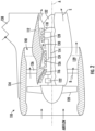
- FIG. 1 illustrates an example of a commercial aircraft 10 having aircraft engines surrounded by (or otherwise carried in) a nacelles 20.
- the aircraft 10 includes two wings 22 that can each include one or more slats 24 and one or more flaps 26.
- the aircraft may further include ailerons 27, spoilers 28, horizontal stabilizer trim tabs 29, horizontal stabilizer 30 and rudder 31, and vertical stabilizer 32 (the tail structure being collectively referred to as an and empennage) each of which may be typically referred to as "control surfaces" as they are movable under aircraft power systems.
- the leading edges of the wings and nacelles are especially vulnerable to the formation of ice.
- a turbine 110 is shown in FIG. 2 .
- a pylon 138 secures the engine 10 to an aircraft.
- the engine 110 includes a core nacelle 112 that houses a low pressure spool 114 (the low spool 114) and a high pressure spool 124 (the high spool 124) rotatable about an axis A.
- the low spool 114 supports a low pressure compressor 116 and low pressure turbine 118.
- the low spool 14 drives a turbofan 120 through a gear train 122.
- the high spool 124 supports a high pressure compressor 126 and high pressure turbine 128.
- a combustor 130 is arranged between the high pressure compressor 126 and high pressure turbine 128.
- Compressed air from compressors 116, 126 mixes with fuel from the combustor 130 and is expanded in turbines 118, 128.
- Airflow enters a fan nacelle 134, which surrounds the core nacelle 12 and turbofan 120.
- the turbofan 120 directs air into the core nacelle 112, which is used to drive the turbines 118, 128, as is known in the art.
- Turbine exhaust E exits the core nacelle 112 once it has been expanded in the turbines 118, 128, in a passage provided between the core nacelle and a tail cone 132.
- the core nacelle 112 is supported within the fan nacelle 134 by structure 136, which are commonly referred to as upper and lower bifurcations.
- a generally annular bypass flow path 139 is arranged between the core and fan nacelles 112, 134.
- the example illustrated in FIG. 2 depicts a high bypass flow arrangement in which approximately eighty percent of the airflow entering the fan nacelle 134 bypasses the core nacelle 112.
- the bypass flow B within the bypass flow path 139 exits the fan nacelle 134 through a nozzle exit area 140.
- Thrust is a function of density, velocity and area. One or more of these parameters can be manipulated to vary the amount and direction of thrust provided by the bypass flow B.
- the engine 110 includes a structure associated with the nozzle exit area 40 to change the physical area and geometry to manipulate the thrust provided by the bypass flow B.
- the nozzle exit area might be effectively altered by other than structural changes, for example, by altering the boundary layer, which changes the flow velocity.
- any device used to effectively change the nozzle exit area is not limited to physical locations near the exit of the fan nacelle 134, but rather, includes altering the bypass flow B at any suitable location in the bypass flow path.
- energy to power one or more accessories 150 may be obtained from the low spool 114 through an intermediate transmission 200.
- the transmission 200 may be connected to the engine 110 by one or more bevel gears 210 and through a shaft 220 functioning as input shaft for the transmission 200.
- a first bevel gear 210a is coupled to the low spool 114.
- the first bevel gear 210a meshes with and transfers rotational power to a second bevel gear 210b that is connected to the input shaft 220.
- the accessories 150 may be powered by an output shaft 230 extending between the transmission 200 and the accessories 150. Extracting power from the low spool 124 may allow the high spool 114 to be made more efficient while also allowing for a lower idle speed which decreases brake wear. A difference in optimum speed ratios between accessories 150 and the low spool 114 may hinder an ability to extract power from the low spool 114. Optimum accessory speed ratio ranges may be approximately 2:1 while speed ratio ranges in the low spool 114 may be as high as 10:1. According to an embodiment, the transmission 200 disclosed herein may convert a large input speed ratio range (8:1) from the low spool 114 into a smaller output speed ratio range (2:1) for driving engine accessories 150.
- Speed sensors generally identified as 250 including a first speed sensor 250a on the input shaft 220 for the transmission and a second speed sensor 250b on the transmission output shaft 230, may communicate with a transmission controller 260 to initiate shifting though one or more clutches and one or more band brakes (disclosed in detail below). Overlapping ranges between the speed ratios may be provided to prevent "doorbelling" at the shift points.
- the disclosed transmission may convert a wide input speed range (8:1) into a narrower output speed range (2:1) for engine accessories 150.
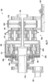
- the transmission 200 includes the input shaft 220 configured to operationally connect to the low pressure section 114 of the gas turbine engine 110.
- the output shaft 230 is configured to drive an aircraft accessory 150 ( FIG. 3 ).
- a gear system generally referred to as 330 is connected between the input shaft 220 and the output shaft 230.
- the gear system 330 includes
- the plurality of clutches 420 comprises a first clutch 420a, a second clutch 420b, a third clutch 420c and a fourth clutch 420d.
- the first clutch 420a is configured for being shifted by the engine controller 260 ( FIG. 3 ) between a closed state and an opened state. In the closed state, the first clutch 420a rotationally couples the output shaft 230 with the second sun gear 390. In the opened state, the first clutch 420a rotationally decouples (not rotationally couple) the output shaft 230 from the second sun gear 390.
- the second clutch 420b is configured for being shifted between a closed state and an opened state. In the closed state, the second clutch 420b rotationally couples the output shaft 230 with the second ring gear 380 and the first carrier 370. In the opened state, the second clutch 420b rotationally decouples the output shaft 230 from the second ring gear 380 and the first carrier 370.
- the third clutch 420c is configured for being shifted between a closed state and an opened state. In the closed state, the third clutch 420c rotationally brakes (prevent rotation of) the first sun gear 350. In the opened state, the third clutch 420c rotationally releases from braking (not prevent rotation of) the first sun gear 350.
- the fourth clutch 420d is configured for being shifted between a closed state and an opened state. In the closed state, the fourth clutch 420d rotationally brakes the second ring gear 380 and the first carrier 370. In the opened state, the fourth clutch 420d rotationally releases from braking the second ring gear 380 and the first carrier 370.
- the plurality of transmission speeds are generally referred to as 460 and include a first transmission speed 460a, a second transmission speed 460b, a third transmission speed 460c and a fourth transmission speed 460d.
- the clutches 420 may be configured for operating pursuant to a clutch schedule that is actuated, for example, by the engine controller 260 ( FIG. 3 ).
- the clutches 420 are identified alphabetically in FIGS. 5 and 6 , wherein "A" represents the first clutch 420a, "B” represents the second clutch 420b, "C” represents the third clutch 420c, and "D” represents the fourth clutch 420d.
- A represents the first clutch 420a
- B represents the second clutch 420b
- C represents the third clutch 420c
- D represents the fourth clutch 420d.
- IPG represents the input (first) planetary gear system 330a
- OPG represents output (second) planetary gear system 330b
- S represents the sun gear (350 or 390) for respective gear system 330
- R represents the ring gear (340 or 380) for respective gear system 330
- C represents the planetary carrier (370 or 410) for respective gear system 330.
- the output shaft 230 may be engaged to convert speed and power at the input shaft 220 to speed and power at the output shaft 230.
- Engaging the output shaft 230 is achieved by shifting one or both of the first clutch 420a and the second clutch 420b to the closed state.
- two of the plurality of clutches 420 are opened and another two of the plurality of clutches 420 are closed.
- at least one of the first clutch 420a and the second clutch 420b is in the closed state and at least one of the third clutch 420c and the fourth clutch 420d is in the opened state.
- both of the first clutch 420a and the second clutch 420d are in the closed state.
- the first clutch 420a in the first transmission speed 460a, the first clutch 420a may be in the closed state and the second clutch 420b may be in the opened state.
- the third clutch 420c in the opened state, and the fourth clutch 420d may be in the closed state. From this configuration, power is directed from the input shaft 220 to the second carrier 410. The first carrier 370 and the second ring gear 380 are stopped from rotating by action of the fourth clutch 420d. Power travels from the second sun gear 390 to the output shaft 230 by action of the first clutch 420a.
- the first clutch 420a may be in the closed state and the second clutch 420b may be in the opened state.
- the third clutch 420c may be in the closed state, and the fourth clutch 420d may be in the opened state.
- power is directed from the input shaft 220 to the first ring gear 340 and the second carrier 410.
- the first sun gear 350 is stopped from rotating by action of the third clutch 420c.
- the rotational speed of the first carrier 370 and the second ring gear 380 determines the speed of the second sun gear 390 which drives the output shaft 230 through the first clutch 420a.
- Rotational speeds of the first carrier 370 and the second carrier 380 are also a function of the specific gear-tooth ratios of each of the gears in each gear set.
- the configuration of such specific gear-tooth ratios would be appreciated by one of ordinary skill in the art and are therefore not discussed in detail herein.
- the specific gear are not to be confused with the total gear ratios for the gear sets, which is disclosed in detail herein (below) with reference to FIG. 8 .
- the first clutch 420a may be in the closed state and the second clutch 420b may be in the closed state.
- the third clutch 420c may be in the opened state, and the fourth clutch 420d may be in the opened state.
- power is directed from the input shaft 220 to the first ring gear 340 and the second carrier 410.
- the first carrier 370 and the second ring gear 380 engage the output shaft 230 by action of the second clutch 420b.
- the second sun gear 390 engages the output shaft 230 by action of the first clutch 420a.
- the action of the first clutch 420a and second clutch 420b rotationally couples the second sun gear 390 and the second ring gear 380 resulting in a straight-thru condition.
- the output shaft 230 is engaged by parallel action of the first clutch 420a and second clutch 420b.
- the first clutch 420a may be in the opened state and the second clutch 420b may be in the closed state.
- the third clutch 420c may be in the closed state and the fourth clutch 420d may be in the opened state.
- power is directed from the input shaft 220 to the first ring gear 340 and the second carrier 410.
- the first sun gear 350 is stopped from rotating by action of the third clutch 420c.
- the first carrier 370 and the second ring gear 380 transfer power to the output shaft 230 by action of the second clutch 420b.
- the second ring gear 380 functions as a second intermediate output shaft for the transmission 200.
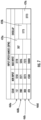
- the first transmission speed 460a and the second transmission speed 460b may overlap by a first overlapping speed range 470a.
- the second transmission speed and third transmission speed may overlap by a second overlapping speed range 470b.
- the second overlapping speed range may be broader than three times the first overlapping speed range.
- the third transmission speed and the fourth transmission speed may overlap by a third overlapping speed range 470c.
- the third overlapping speed range may be broader than five times the first overlapping speed range.
- the minimum input and maximum input speeds for the first transmission speed 460a may be 1250 rpm (revolutions per minute) and 2778 rpm, respectively.
- the minimum input and maximum input speeds for the first transmission speed 460b may be 2271 rpm and 5046 rpm, respectively.
- the minimum input and maximum input speeds for the third transmission speed 460c may be 3273 rpm and 7273 rpm, respectively.
- the minimum input and maximum input speeds for the fourth transmission speed 460d may be 4500 rpm and 1000rpm, respectively.
- the first speed range overlap 470a may be 507 rpm.
- the second speed range overlap 470b may be 1773 rpm.
- the third speed range overlap 470c may be 2773 rpm.
- the first transmission speed 460a may generate a first output/input speed ratio 480a.
- the second transmission speed 460b may generate a second output/input speed ratio 480b.
- the second output/input speed ratio that may be less than sixty percent of the first output/input speed ratio 480a.
- the third transmission speed 460c may generate a third output/input speed ratio 480c.
- the third output/input speed ratio 480c may be less than the second output/input speed ratio 480b and less than forty percent of the first output/input ratio 480a.
- the fourth transmission speed 460d may generate a fourth output/input speed ratio 480d.
- the fourth output/input speed ratio 480d may be less than the third output/input speed ratio 480c and less than thirty percent of the first output/input ratio 480a.
- the first sun gear 350 and second ring gear 380 function as speed trimming gears to produce a desired gear ratio for their respective gear set 330a and 330b .
- the output speed for the gear sets, 330a and 330b may be determined. If the speed of gears 350 and 380 is not known, the output speed for the gear set 330a and 330b may be indeterminate. For example, in the first transmission speed 460a, the speed of the first carrier 370 and the second ring gear 380 is known, because these gears 370, 380 are not spinning (zero rpm).
- a speed of the second carrier 410 is known because its speed is a function of the speed of the input shaft 220.
- the speed of the second sun gear 390 and the speed of the output shaft 230 can then be calculated based on the input/output speed ratios 480 for the transmission 200.
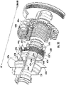
- the transmission 200 may include a plurality of rotors generally referred to as 510.
- the plurality of rotors may include a first rotor 510a and a second rotor 510b.
- the first rotor 510a may be coupled to the second sun gear 390 so that the first rotor 510a may function as a first intermediate output shaft for the transmission 200.
- the first rotor 510a may be a stub shaft that may be axially aligned with the input shaft 220 and the output shaft 230.
- the first rotor 510a may be axially intermediate the input shaft 220 and the output shaft 230.
- the first clutch 420a may be coupled to the first rotor 510a so that engaging the first clutch 420a may engage the first rotor 510a.
- the second rotor 510b may be coupled to the first sun gear 350.
- the third clutch 420c may be a first band brake that may be configured to engage the second rotor 5 10b.
- the fourth clutch 420d may be a second band brake that may be configured to engage the second ring gear 380.
- FIG. 10 further illustrated are the plurality of clutches 420 that are axially aligned and radially offset.
- the plurality of clutches 420 are configured to engage in parallel the output shaft 230 and shift the transmission 200 to generate a plurality gear speeds.
- a plurality of pistons generally referred to as 600 may be configured to engage the respective plurality of clutches 420.
- the plurality of pistons 600 may be hydraulically controlled and adapted to receive fluid from a respective plurality of ports generally referred to as 610 in the output shaft 230.
- the plurality of clutches 420 may include a first clutch 420a and a second clutch 420b.
- the plurality of pistons 600 may include a first piston 600a and a second piston 600b.
- the first piston 600a may engage the first clutch 420a and the second piston 600b may engage the second clutch 420b.
- the plurality of ports 610 in the output shaft may include a first port 610a and a second port 610b.
- the first port 610a may communicate fluid to the first piston 600a.
- the second port 610b may be axially aft of the first port 610a and may fluidly communicate fluid to the second piston 600b.
- the output shaft 230 may include first plurality of segments generally referred to as 620, including a first segment 620a that extends forward to a first axial end 620b from a location 620c on the output shaft 230 that is between the plurality of ports 610.
- a second segment 620d may be radially extending to an aft end 620e of a third segment 620f.
- the third segment 620f may extend axially forward and end at a second axial end 620g that is axially proximate the first axial end 620b.
- a first internal cavity 620h may be defined by the first plurality of segments 620 of the output shaft 230, with the first fluid port 610a being fluidly connected to the first internal cavity 620h.
- An axially aft portion 620i of the first internal cavity 620h may form a housing for the first piston 600a (the first piston housing 620i).
- An axially forward portion 620j of the internal cavity 620h may form a housing for the first clutch 420a (the first clutch housing 620j).
- the first piston housing 620i and the first clutch housing 620j are separated by phantom line 620k for illustrative purposes.
- the first clutch 420a is radially within the first clutch housing 620j.
- the second clutch 420b is radially exterior to the first clutch housing 620j.
- the first piston 600a may be formed by a first slider shaft movably positioned within the first piston housing 620i.
- the first piston 600a may include a second plurality of segments generally referenced by 630, including a fourth segment 630a that is axially extending and configured to slide along the first segment 620a within the piston housing 630i.
- the fourth segment 630a may be sized so that during a full range of motion along the first segment 620a in the first piston housing 620i, the first port 610a remains in fluid communication with the first piston housing 620i.
- a fifth segment 630b may be radially outwardly extending and may be configured to press against the first clutch 420a.
- the fifth segment 630b may connect with a forward end 630c of a sixth segment 630d.
- the sixth segment 630d may extend axially aft by a span that is the same as the axial span of the first piston housing 630i.
- the sixth segment 630d may be configured to slide along the third member 620f within the piston housing 630i.
- a radially outward lip 630e extending from the fifth segment 630b engages the output shaft 230 to rotate with the output shaft 230.
- fluid action through the first port 610a moves the first piston 600a in forward and aft directions to engage and release the first clutch 420a.
- the second piston 600b may be formed by a second slider shaft movably positioned between the output shaft 230 aft of the second segment 620d, and second intermediate output shaft 380.
- the second piston 600b includes a second plurality of segments generally referenced by 650, including a seventh segment 650a that is axially extending and configured to slide along the output shaft 230. Connected to a forward end 650b of the seventh segment 650a is an eighth segment 650c that is radially outwardly extending, parallel with the second segment 655d, and connects with an aft end 650d of a ninth segment 650e.
- the ninth segment 650e extends axially aft to at least partially slide against the third segment 630f of the output shaft 230.
- the ninth segment 650e extends axially aft to a radially inner end 650f of a tenth segment 650g.
- the tenth segment 650g extends axially to the second intermediate output shaft 380 and is configured to engage the second clutch 420b.
- a second internal cavity 650h identified forward of phantom line 650i in the second piston 600b, is formed between the second piston 600b and the output shaft 230.
- the second piston 600b is configured so that the second fluid port 610b remains in fluid communication with the second internal cavity 650h. Fluid action through the second port 610b moves the second piston 600b in forward and aft directions to engage and release the second clutch 420b.
- a radially inner lip 650j extending from the tenth member 650g engages the output shaft 230 to rotate with the output shaft 230.
- a radially outer lip 650k extending from the tenth member 650g engages with the second intermediate output shaft 380 to rotate with the second intermediate output shaft.
- the transmission 200 includes a plurality of splines generally referenced as 655.
- the first clutch housing 620j may include a first spline 655a that is a radially inner spline and a second spline 655b that is a radial outer spline.
- the first piston 600a may include a third spline 655c that is a radial outer spline configured to engage with the first spline 655a.
- the third spline 655c may extend from the radially extending lip 630e of the first piston 600a.
- the second piston 600b may include a fourth spline 655d that may be a radial inner spline configured to engage with the second spline 655b.
- the fourth spline 655d may extend from the radially extending lip 650j.
- the second intermediate output shaft 380 may include a fifth spline 655e that may be a radially inner spline.
- the second piston 600b may include a sixth spline 655f that may be is radially outer spline configured to engage with the fifth spline 655e.
- the sixth spline 655f may extend from the radial extending lip 650k of the second piston 600b.
- the first intermediate output shaft 510a may have a seventh spline 655g that may be a radially outer spline.
- the first clutch 420a may include an eighth spline 655h that may be a radially inner spline configured to engage with the seventh spline 655g.
- a ninth spline 655i in the first clutch 420a may be is a radially outer spline configured to engage with the first spline 655a.
- the second clutch 420b may include a tenth spline 655j that may be a radially inner spline configured to engage with the second spline 655b.
- an eleventh spline 655k may be provided in the second clutch 420b.
- the eleventh spline 655k may be a radially outer spline configured to engage with the second intermediate output shaft 380.
- each of the clutches 420 has an inner spline and an outer spline. This is achieved by utilizing a clutch pack with alternating discs generally referred to as 656 having splines facing alternating radial directions.
- the first clutch 420a may have an inner clutch separator plate 656a and an inner clutch friction plate 656b.
- the second clutch 420b may have an inner clutch separator plate 656c and an inner clutch friction plate 656d.
- Each of the discs 656 has a series of spline teeth generally referred to as 657 on an inner diameter edge generally referred to as 658 or an outer diameter edge generally referred to as 659.
- the inner clutch separator plate 656a has spline teeth 657a on the outer diameter edge 659a and the inner clutch friction plate 656b has spline teeth 657b on the inner diameter edge 658b.
- the inner clutch separator plate 656c has spline teeth 657c on the inner diameter edge 658c and the inner clutch friction plate 656d has spline teeth 657d on the outer diameter edge 659d.
- the clutches 420 when the clutches 420 are not engaged, the alternating discs in each clutch pack rotate freely relative to each other.
- the clutch packs rotate in unison.
- the first clutch 420a when engaged, will cause the first intermediate out shaft 510a to rotate with the output shaft 230. Otherwise the first intimidate output shaft 510a rotates freely relative to the output shaft 230.
- the second clutch 420b when engaged, will cause the second intermediate output shaft 380 to rotate with the output shaft 230. Otherwise the second intimidate output shaft 380 rotates freely relative to the output shaft 230.
- the seals 600 may include a first seal 660a and a second seal 660b in the first piston housing 620a and engage the first piston 600a to fluidly constrain fluid flowing to the first piston 600a from the first fluid port 610a.
- the first seal 660a may be an axially forward seal located between the first piston 600a and the first segment 620a of the output shaft 230.
- the second seal 660b may be an axially aft seal located between the first piston 600a and the third segment 620f of the output shaft 230.
- a third seal 660c and a fourth seal 660d may engage the second piston 600b to fluidly constrain fluid flowing to the second piston 600b from the second fluid port 610b.
- the third seal 660c may be an axially forward seal located between the second piston 600b and the output shaft 230.
- the fourth seal 660d may be an axially aft seal located between the second piston 600b and the third segment 620f of the output shaft 230.
- the output shaft 230 may include an internal annulus 670, disposed forward of the plurality of ports 610.
- the internal annulus 670 may be configured to seal fluid within the output shaft 230 from flowing forward thereof.
- a first piston return spring 680 may be disposed axially between the first piston 600a and an annulus 690 fixed to the output shaft 230, wherein the annulus 690 may be axially forward of the first piston 600a.
- the first piston return spring 680 may bias the first piston 600a to disengage the first clutch 420a.
- the first piston 600a may include an axial channel 700 in the fourth member 630a for seating the first piston return spring 680 therein.
- the first piston return spring 680 may engage the annulus 690 for biasing the first piston 600b to disengage the first clutch 420a.
- a second piston return spring 720 may be disposed axially between the second piston 600b and an annulus 730 fixed to the output shaft 230, wherein the annulus 730 may be positioned aft of the second piston 600b.
- the second piston return spring 720 may bias the second piston 600b to engage the second clutch 420b.
- a rolling element bearing 740 may be disposed between the first intermediate output shaft 510a and output shaft 230.
Landscapes
- Engineering & Computer Science (AREA)
- General Engineering & Computer Science (AREA)
- Chemical & Material Sciences (AREA)
- Combustion & Propulsion (AREA)
- Mechanical Engineering (AREA)
- Structure Of Transmissions (AREA)
Description
- This application relates to a speed gearbox and more particularly to a coupled planetary gearbox driven for an aircraft system.
- An increasing number of aircraft require significant electric power for operation. Various components may be driven by a high pressure spool through a power takeoff shaft. Due to modem aircraft engine efficiency requirements, electric power demand may be increasing beyond the power extraction potential of the engine high pressure spool.
EP 2 955 418 A1WO 2008/044972 A1 describes a device for retrieval of power from a gas turbine engine.EP 0524791A2 describes a T-drive power/train assembly.US 2002/183154 A1 describes a drive system for a motor vehicle. - Disclosed is a transmission as defined in
claim 1, including: an input shaft configured to operationally connect to a low pressure section of a gas turbine engine; an output shaft configured to drive an engine an aircraft accessory; a gear system connected between the input shaft and the output shaft, the gear system including: a first epicyclical gear set that includes a first ring gear coupled to the input shaft, a first sun gear, a first planetary gear set, and a first planetary carrier connected to the first planetary gear set; and a second epicyclical gear set that includes a second ring gear, a second sun gear, a second planetary gear set, and a second planetary carrier connected to the second planetary gear set, wherein: the input shaft is coupled to the first ring gear and the second planetary carrier; and the first planetary carrier is coupled to the second ring gear; and a plurality of clutches that engage the first epicyclical gear set and the second epicyclical gear set, the plurality of clutches being adapted for shifting the transmission to generate a plurality of respectively overlapping transmission speeds. - The plurality of clutches comprises: a first clutch configured for being shifted between: a closed state, to rotationally couple the output shaft with the second sun gear; and an opened state to rotationally decouple the output shaft from the second sun gear; a second clutch configured for being shifted between: a closed state to rotationally couple the output shaft with the second ring gear and the first planetary carrier; and an opened state to rotationally decouple the output shaft from the second ring gear and the first planetary carrier; a third clutch configured for being shifted between: a closed state to rotationally brake the first sun gear; and an opened state to rotationally release from braking the first sun gear; and a fourth clutch configured for being shifted between: a closed state to rotationally brake the second ring gear and the first planetary carrier; and an opened state to rotationally release from braking the second ring gear and the first planetary carrier.
- For each of the plurality of transmission speeds, the output shaft is configured to be engaged by: shifting the first clutch to the closed state; and/or shifting the second clutch to the closed state.
- For each of the plurality of transmission speeds: two of the plurality of clutches are opened; and another two of the plurality of clutches are closed.
- For each of the plurality of transmission speeds: at least one of the first clutch and the second clutch is in the closed state; and at least one of the third clutch and the fourth clutch is in the opened state; and for at least one of the plurality of transmission speeds: both of the first clutch and second clutch are in the closed state.
- In addition to one or more of the above features, the plurality of transmission speeds include a first transmission speed, wherein: the first clutch is in the closed state; the second clutch is in the opened state; the third clutch is in the opened state; and the fourth clutch is in the closed state.
- In addition to one or more of the above features, the plurality of transmission speeds include a second transmission speed, wherein: the first clutch is in the closed state; the second clutch is in the opened state; the third clutch is in the closed state; and the fourth clutch is in the opened state.
- In addition to one or more of the above features, the plurality of transmission speeds include a third transmission speed, wherein: the first clutch is in the closed state; the second clutch is in the closed state; the third clutch is in the opened state; and the fourth clutch is in the opened state.
- In addition to one or more of the above features, the plurality of transmission speeds include a fourth transmission speed, wherein: the first clutch is in the opened state; the second clutch is in the closed state; the third clutch is in the closed state; and the fourth clutch is in the opened state.
- In addition to one or more of the above features: the first transmission speed and the second transmission speed overlap by a first overlapping speed range; the second transmission speed and the third transmission speed overlap by a second overlapping speed range that is broader than three times the first overlapping speed range; and the third transmission speed and the fourth transmission speed overlap by a third overlapping speed range that is broader than five times the first overlapping speed range.
- In addition to one or more of the above features: the first transmission speed generates a first output/input speed ratio; the second transmission speed generates a second output/input speed ratio that is less than sixty percent of the first output/input speed ratio; the third transmission speed generates a third output/input speed ratio that is less than the second output/input speed ratio and less than forty percent of the first output/input ratio; and the fourth transmission speed generates a fourth output/input speed ratio that is less than the third output/input speed ratio and less than thirty percent of the first output/input ratio.
- In addition to one or more of the above features: a first spline that connects: the first clutch to the second sun gear; and the first clutch to the output shaft; and a second spline that connects: the second clutch to the second ring gear; and the second clutch to the output shaft.
- In addition to one or more of the above features: a first rotor coupled to the second sun gear, and the first rotor being a stub shaft that is: axially aligned with the input shaft and the output shaft; and axially intermediate the input shaft and the output shaft; wherein the first clutch is coupled to the first rotor so that engaging the first clutch engages the first rotor; a second rotor coupled to the first sun gear; wherein the third clutch is a first band brake configured to engage the second rotor; and the fourth clutch is a second band brake configured to engage the second ring gear.
- Disclosed is a method of transmitting rotational speed as defined in claim 9, comprising: providing a first epicyclical gear set that includes a first sun gear, a first ring gear surrounding the first sun gear, a first planetary gear set that mechanically couples the first sun gear to the first ring gear, and a first planetary carrier connected to the first planetary gear set; providing a second epicyclical gear set that includes a second sun gear, a second ring gear surrounding the second sun gear, a second planetary gear set that mechanically couples the second sun gear to the second ring gear, and a second planetary carrier connected to the second planetary gear set; driving from an input shaft of the transmission: the first ring gear, thereby driving the first planetary gear set, and the first planetary carrier; and the second planetary carrier, thereby driving the second planetary gear set, and the second sun gear; driving, from the first planetary carrier, the second ring gear; and controlling a plurality of clutches in the transmission to engage the first epicyclical gear set and the second epicyclical gear set, thereby shifting the transmission between a plurality of transmission speeds that are respectively overlapping.
- Controlling the plurality of clutches includes one or more of shifting a first clutch of the plurality of clutches between: a closed state, to rotationally couple the output shaft with the second sun gear; and an opened state to rotationally decouple the output shaft from the second sun gear; shifting a second clutch of the plurality of clutches between: a closed state to rotationally couple the output shaft with the second ring gear and the first planetary carrier; and an opened state to rotationally decouple the output shaft from the second ring gear and the first planetary carrier; shifting a third clutch of the plurality of clutches between: a closed state to rotationally brake the first sun gear; and an opened state to rotationally release from braking the first sun gear; shifting a fourth clutch of the plurality of clutches between: a closed state to rotationally brake the second ring gear and the first planetary carrier; and an opened state to rotationally release from braking the second ring gear and the first planetary carrier.
- For each of the plurality of transmission speeds, controlling the plurality of clutches includes engaging the output shaft in parallel by: shifting the first clutch to the closed state; and shifting the second clutch to the closed state.
- In addition to one or more of the above features, the method may include generating a first transmission speed of the plurality of transmission speeds by: shifting the first clutch to the closed state; shifting the second clutch to the opened state; shifting the third clutch to the opened state; and shifting the fourth clutch to the closed state.
- In addition to one or more of the above features, the method may include generating a second transmission speed of the plurality of transmission speeds by: shifting the first clutch to the closed state; shifting the second clutch to the opened state; shifting the third clutch to the closed state; and shifting the fourth clutch to the opened state.
- In addition to one or more of the above features, the method may include generating a third transmission speed of the plurality of transmission speeds by: shifting the first clutch to the closed state; shifting the second clutch to the closed state; shifting the third clutch to the opened state; and shifting the fourth clutch to the opened state.
- In addition to one or more of the above features, the method may include generating a fourth transmission speed of the plurality of transmission speeds by: shifting the first clutch to the opened state; shifting the second clutch to the closed state; shifting the third clutch to the closed state; and shifting the fourth clutch to the opened state.
- The following descriptions should not be considered limiting in any way. With reference to the accompanying drawings, like elements are numbered alike:
-
FIG. 1 is a perspective view of an aircraft that includes aerodynamic surfaces where embodiments of the present invention can be implemented; -
FIG. 2 illustrates a cross section of a gas turbine engine wherein embodiments of the present invention can be implemented; -
FIG. 3 schematically illustrates features of a gas turbine engine including a transmission transferring power between a low spool and an accessory according to an embodiment; -
FIG. 4 illustrates features of a transmission according to an embodiment; -
FIG. 5 lists a clutch schedule for providing different transmission speeds for a disclosed transmission according to an embodiment; -
FIG. 6 schematically illustrates an implementation of a clutch schedule for providing different transmission speeds for a disclosed transmission according to an embodiment; -
FIG. 7 lists overlapping speed ranges for different transmission speeds for a disclosed transmission according to an embodiment; -
FIG. 8 is a graph of output/input ratios for different transmission speeds according to an embodiment; -
FIG. 9 illustrates additional features of a transmission according to an embodiment; -
FIG. 10 illustrates additional features of an output shaft of a transmission according to an embodiment; -
FIG. 11 illustrates additional features of pistons that engage clutches to engage an output shaft of a transmission according to an embodiment; -
FIG. 12 illustrates additional features of splines that provide for coupled rotation between the output shaft, pistons and clutches of a transmission according to an embodiment; -
FIGS. 13A-13D illustrate clutch plates that may be utilized in clutches of a transmission according to an embodiment; and -
FIG. 14 illustrates additional features including seals and return springs associated with operation of pistons and clutches of a transmission according to an embodiment. - A detailed description of one or more embodiments of the disclosed apparatus and method are presented herein by way of exemplification and not limitation with reference to the Figures.
-
FIG. 1 illustrates an example of acommercial aircraft 10 having aircraft engines surrounded by (or otherwise carried in) anacelles 20. Theaircraft 10 includes twowings 22 that can each include one ormore slats 24 and one ormore flaps 26. The aircraft may further includeailerons 27,spoilers 28, horizontalstabilizer trim tabs 29,horizontal stabilizer 30 andrudder 31, and vertical stabilizer 32 (the tail structure being collectively referred to as an and empennage) each of which may be typically referred to as "control surfaces" as they are movable under aircraft power systems. The leading edges of the wings and nacelles are especially vulnerable to the formation of ice. - A
turbine 110 is shown inFIG. 2 . Apylon 138 secures theengine 10 to an aircraft. Theengine 110 includes acore nacelle 112 that houses a low pressure spool 114 (the low spool 114) and a high pressure spool 124 (the high spool 124) rotatable about an axis A. Thelow spool 114 supports alow pressure compressor 116 andlow pressure turbine 118. In the example, the low spool 14 drives aturbofan 120 through agear train 122. Thehigh spool 124 supports ahigh pressure compressor 126 andhigh pressure turbine 128. Acombustor 130 is arranged between thehigh pressure compressor 126 andhigh pressure turbine 128. Compressed air fromcompressors combustor 130 and is expanded inturbines fan nacelle 134, which surrounds the core nacelle 12 andturbofan 120. Theturbofan 120 directs air into thecore nacelle 112, which is used to drive theturbines core nacelle 112 once it has been expanded in theturbines tail cone 132. Thecore nacelle 112 is supported within thefan nacelle 134 bystructure 136, which are commonly referred to as upper and lower bifurcations. A generally annularbypass flow path 139 is arranged between the core andfan nacelles FIG. 2 depicts a high bypass flow arrangement in which approximately eighty percent of the airflow entering thefan nacelle 134 bypasses thecore nacelle 112. The bypass flow B within thebypass flow path 139 exits thefan nacelle 134 through anozzle exit area 140. For theengine 110 shown inFIG. 2 , a significant amount of thrust may be provided by the bypass flow B due to the high bypass ratio. Thrust is a function of density, velocity and area. One or more of these parameters can be manipulated to vary the amount and direction of thrust provided by the bypass flow B. In one example, theengine 110 includes a structure associated with the nozzle exit area 40 to change the physical area and geometry to manipulate the thrust provided by the bypass flow B. However, it should be understood that the nozzle exit area might be effectively altered by other than structural changes, for example, by altering the boundary layer, which changes the flow velocity. Furthermore, it should be understood that any device used to effectively change the nozzle exit area is not limited to physical locations near the exit of thefan nacelle 134, but rather, includes altering the bypass flow B at any suitable location in the bypass flow path. - As illustrated in
FIG. 3 , according to the disclosure, energy to power one ormore accessories 150 may be obtained from thelow spool 114 through anintermediate transmission 200. Thetransmission 200 may be connected to theengine 110 by one ormore bevel gears 210 and through ashaft 220 functioning as input shaft for thetransmission 200. As shown a first bevel gear 210a is coupled to thelow spool 114. The first bevel gear 210a meshes with and transfers rotational power to a second bevel gear 210b that is connected to theinput shaft 220. - The
accessories 150 may be powered by anoutput shaft 230 extending between thetransmission 200 and theaccessories 150. Extracting power from thelow spool 124 may allow thehigh spool 114 to be made more efficient while also allowing for a lower idle speed which decreases brake wear. A difference in optimum speed ratios betweenaccessories 150 and thelow spool 114 may hinder an ability to extract power from thelow spool 114. Optimum accessory speed ratio ranges may be approximately 2:1 while speed ratio ranges in thelow spool 114 may be as high as 10:1. According to an embodiment, thetransmission 200 disclosed herein may convert a large input speed ratio range (8:1) from thelow spool 114 into a smaller output speed ratio range (2:1) for drivingengine accessories 150. Speed sensors generally identified as 250, including afirst speed sensor 250a on theinput shaft 220 for the transmission and asecond speed sensor 250b on thetransmission output shaft 230, may communicate with atransmission controller 260 to initiate shifting though one or more clutches and one or more band brakes (disclosed in detail below). Overlapping ranges between the speed ratios may be provided to prevent "doorbelling" at the shift points. The disclosed transmission may convert a wide input speed range (8:1) into a narrower output speed range (2:1) forengine accessories 150. - Turning to
FIG. 4 , disclosed in greater detail is thetransmission 200. Thetransmission 200 includes theinput shaft 220 configured to operationally connect to thelow pressure section 114 of thegas turbine engine 110. Theoutput shaft 230 is configured to drive an aircraft accessory 150 (FIG. 3 ). A gear system generally referred to as 330 is connected between theinput shaft 220 and theoutput shaft 230. - The gear system 330 includes
- a first epicyclical gear set 330a (the first gear set 330a) and a second epicyclical gear set 330b (the second gear set 330b). The
first gear set 330a includes - a
first ring gear 340, afirst sun gear 350, a first planetary gear set 360, and a first planetary carrier 370 (the first carrier 370). Thefirst carrier 370 is connected to the first planetary gear set 360. Thesecond gear set 330b includes - a
second ring gear 380, asecond sun gear 390, a second planetary gear set 400, and a second planetary carrier 410 (the second carrier 410). Thesecond carrier 410 is connected to the second planetary gear set 400. Theinput shaft 220 is coupled to thefirst ring gear 340 and thesecond carrier 410. In addition, thesecond ring gear 380 is coupled to thefirst carrier 370. In addition, a plurality of clutches generally referred to as 420 engages the first gear set 330a and thesecond gear set 330b. The plurality of clutches 420 is adapted for shifting thetransmission 200 to generate a plurality of respectively overlapping transmission speeds, discussed in greater detail below. In one embodiment, thesecond gear set 330b may be axially adjacent to the first gear set 330a. - The plurality of clutches 420 comprises a first clutch 420a, a second clutch 420b, a third clutch 420c and a fourth clutch 420d. The first clutch 420a is configured for being shifted by the engine controller 260 (
FIG. 3 ) between a closed state and an opened state. In the closed state, the first clutch 420a rotationally couples theoutput shaft 230 with thesecond sun gear 390. In the opened state, the first clutch 420a rotationally decouples (not rotationally couple) theoutput shaft 230 from thesecond sun gear 390. - The second clutch 420b is configured for being shifted between a closed state and an opened state. In the closed state, the second clutch 420b rotationally couples the
output shaft 230 with thesecond ring gear 380 and thefirst carrier 370. In the opened state, the second clutch 420b rotationally decouples theoutput shaft 230 from thesecond ring gear 380 and thefirst carrier 370. - The third clutch 420c is configured for being shifted between a closed state and an opened state. In the closed state, the third clutch 420c rotationally brakes (prevent rotation of) the
first sun gear 350. In the opened state, the third clutch 420c rotationally releases from braking (not prevent rotation of) thefirst sun gear 350. - The fourth clutch 420d is configured for being shifted between a closed state and an opened state. In the closed state, the fourth clutch 420d rotationally brakes the
second ring gear 380 and thefirst carrier 370. In the opened state, the fourth clutch 420d rotationally releases from braking thesecond ring gear 380 and thefirst carrier 370. - Turning to
FIGS. 5 and 6 , the plurality of transmission speeds are generally referred to as 460 and include afirst transmission speed 460a, asecond transmission speed 460b, athird transmission speed 460c and afourth transmission speed 460d. For each of the transmission speeds 460, the clutches 420 may be configured for operating pursuant to a clutch schedule that is actuated, for example, by the engine controller 260 (FIG. 3 ). The clutches 420 are identified alphabetically inFIGS. 5 and 6 , wherein "A" represents the first clutch 420a, "B" represents the second clutch 420b, "C" represents the third clutch 420c, and "D" represents the fourth clutch 420d. In addition, inFIG. 6 , "IPG" represents the input (first)planetary gear system 330a, "OPG" represents output (second)planetary gear system 330b, "S" represents the sun gear (350 or 390) for respective gear system 330, "R" represents the ring gear (340 or 380) for respective gear system 330, and "C" represents the planetary carrier (370 or 410) for respective gear system 330. - For each of the plurality of transmission speeds 460, the
output shaft 230 may be engaged to convert speed and power at theinput shaft 220 to speed and power at theoutput shaft 230. Engaging theoutput shaft 230 is achieved by shifting one or both of the first clutch 420a and the second clutch 420b to the closed state. In addition, for each of the transmission speeds 460, two of the plurality of clutches 420 are opened and another two of the plurality of clutches 420 are closed. For each of the transmission speeds 460, at least one of the first clutch 420a and the second clutch 420b is in the closed state and at least one of the third clutch 420c and the fourth clutch 420d is in the opened state. In addition, for at least one of the transmission speeds 460, both of the first clutch 420a and the second clutch 420d are in the closed state. - As illustrated in
FIG. 5 , in thefirst transmission speed 460a, the first clutch 420a may be in the closed state and the second clutch 420b may be in the opened state. In addition, in thefirst transmission speed 460a, the third clutch 420c may be in the opened state, and the fourth clutch 420d may be in the closed state. From this configuration, power is directed from theinput shaft 220 to thesecond carrier 410. Thefirst carrier 370 and thesecond ring gear 380 are stopped from rotating by action of the fourth clutch 420d. Power travels from thesecond sun gear 390 to theoutput shaft 230 by action of the first clutch 420a. - In the
second transmission speed 460b, the first clutch 420a may be in the closed state and the second clutch 420b may be in the opened state. In addition, in thesecond transmission speed 460b, the third clutch 420c may be in the closed state, and the fourth clutch 420d may be in the opened state. From this configuration, power is directed from theinput shaft 220 to thefirst ring gear 340 and thesecond carrier 410. Thefirst sun gear 350 is stopped from rotating by action of the third clutch 420c. The rotational speed of thefirst carrier 370 and thesecond ring gear 380 determines the speed of thesecond sun gear 390 which drives theoutput shaft 230 through the first clutch 420a. - Rotational speeds of the
first carrier 370 and thesecond carrier 380 are also a function of the specific gear-tooth ratios of each of the gears in each gear set. However, the configuration of such specific gear-tooth ratios would be appreciated by one of ordinary skill in the art and are therefore not discussed in detail herein. The specific gear are not to be confused with the total gear ratios for the gear sets, which is disclosed in detail herein (below) with reference toFIG. 8 . - In the
third transmission speed 460d, the first clutch 420a may be in the closed state and the second clutch 420b may be in the closed state. In addition, in thethird transmission speed 460c, the third clutch 420c may be in the opened state, and the fourth clutch 420d may be in the opened state. From this configuration, power is directed from theinput shaft 220 to thefirst ring gear 340 and thesecond carrier 410. Thefirst carrier 370 and thesecond ring gear 380 engage theoutput shaft 230 by action of the second clutch 420b. Thesecond sun gear 390 engages theoutput shaft 230 by action of the first clutch 420a. By the principle of operation of an epicyclical gear set, a straight-thru condition is achieved whenever two components of the gear set are rotationally coupled. The action of the first clutch 420a and second clutch 420b rotationally couples thesecond sun gear 390 and thesecond ring gear 380 resulting in a straight-thru condition. Thus, theoutput shaft 230 is engaged by parallel action of the first clutch 420a and second clutch 420b. - In the
fourth transmission speed 460d, the first clutch 420a may be in the opened state and the second clutch 420b may be in the closed state. In addition, in thefourth transmission speed 460c, the third clutch 420c may be in the closed state and the fourth clutch 420d may be in the opened state. From this configuration, power is directed from theinput shaft 220 to thefirst ring gear 340 and thesecond carrier 410. Thefirst sun gear 350 is stopped from rotating by action of the third clutch 420c. Thefirst carrier 370 and thesecond ring gear 380 transfer power to theoutput shaft 230 by action of the second clutch 420b. As such, thesecond ring gear 380 functions as a second intermediate output shaft for thetransmission 200. - Turning to
FIG. 7 , thefirst transmission speed 460a and thesecond transmission speed 460b may overlap by a firstoverlapping speed range 470a. In addition, the second transmission speed and third transmission speed may overlap by a secondoverlapping speed range 470b. The second overlapping speed range may be broader than three times the first overlapping speed range. Further, the third transmission speed and the fourth transmission speed may overlap by a thirdoverlapping speed range 470c. The third overlapping speed range may be broader than five times the first overlapping speed range. - As illustrated, in one embodiment, the minimum input and maximum input speeds for the
first transmission speed 460a may be 1250 rpm (revolutions per minute) and 2778 rpm, respectively. The minimum input and maximum input speeds for thefirst transmission speed 460b may be 2271 rpm and 5046 rpm, respectively. The minimum input and maximum input speeds for thethird transmission speed 460c may be 3273 rpm and 7273 rpm, respectively. The minimum input and maximum input speeds for thefourth transmission speed 460d may be 4500 rpm and 1000rpm, respectively. The firstspeed range overlap 470a may be 507 rpm. The secondspeed range overlap 470b may be 1773 rpm. The thirdspeed range overlap 470c may be 2773 rpm. These speed ranges and speed range overlaps given inFIG. 7 are for reference only and are not intended to be limiting. - Turning to
FIG. 8 , thefirst transmission speed 460a may generate a first output/input speed ratio 480a. In addition, thesecond transmission speed 460b may generate a second output/input speed ratio 480b. The second output/input speed ratio that may be less than sixty percent of the first output/input speed ratio 480a. Thethird transmission speed 460c may generate a third output/input speed ratio 480c. The third output/input speed ratio 480c may be less than the second output/input speed ratio 480b and less than forty percent of the first output/input ratio 480a. Thefourth transmission speed 460d may generate a fourth output/input speed ratio 480d. The fourth output/input speed ratio 480d that may be less than the third output/input speed ratio 480c and less than thirty percent of the first output/input ratio 480a. As illustrated, the first output/input speed ratio 480a may follow an equation of Y=5.775X, which is a linear equation where X is the input speed and Y is the output speed. The second output/input speed ratio 480b may follow an equation of Y=3.175X. The third output/input speed ratio 480c may follow an equation of Y=1.600X. - As provided in the above disclosure, the
first sun gear 350 andsecond ring gear 380 function as speed trimming gears to produce a desired gear ratio for their respective gear set 330a and 330b . By selectively braking these gears, 350 and 380, the output speed for the gear sets, 330a and 330b, may be determined. If the speed ofgears gear set first transmission speed 460a, the speed of thefirst carrier 370 and thesecond ring gear 380 is known, because thesegears second carrier 410 is known because its speed is a function of the speed of theinput shaft 220. The speed of thesecond sun gear 390 and the speed of theoutput shaft 230 can then be calculated based on the input/output speed ratios 480 for thetransmission 200. - Turning to
FIG. 9 , thetransmission 200 may include a plurality of rotors generally referred to as 510. The plurality of rotors may include afirst rotor 510a and asecond rotor 510b. Thefirst rotor 510a may be coupled to thesecond sun gear 390 so that thefirst rotor 510a may function as a first intermediate output shaft for thetransmission 200. Thefirst rotor 510a may be a stub shaft that may be axially aligned with theinput shaft 220 and theoutput shaft 230. Thefirst rotor 510a may be axially intermediate theinput shaft 220 and theoutput shaft 230. The first clutch 420a may be coupled to thefirst rotor 510a so that engaging the first clutch 420a may engage thefirst rotor 510a. Thesecond rotor 510b may be coupled to thefirst sun gear 350. In addition, the third clutch 420c may be a first band brake that may be configured to engage the second rotor 5 10b. The fourth clutch 420d may be a second band brake that may be configured to engage thesecond ring gear 380. - Turning to
FIG. 10 , further illustrated are the plurality of clutches 420 that are axially aligned and radially offset. The plurality of clutches 420, as indicated, are configured to engage in parallel theoutput shaft 230 and shift thetransmission 200 to generate a plurality gear speeds. A plurality of pistons generally referred to as 600 may be configured to engage the respective plurality of clutches 420. The plurality of pistons 600 may be hydraulically controlled and adapted to receive fluid from a respective plurality of ports generally referred to as 610 in theoutput shaft 230. - The plurality of clutches 420 may include a first clutch 420a and a second clutch 420b. The plurality of pistons 600 may include a
first piston 600a and asecond piston 600b. Thefirst piston 600a may engage the first clutch 420a and thesecond piston 600b may engage the second clutch 420b. The plurality of ports 610 in the output shaft may include afirst port 610a and asecond port 610b. Thefirst port 610a may communicate fluid to thefirst piston 600a. Thesecond port 610b may be axially aft of thefirst port 610a and may fluidly communicate fluid to thesecond piston 600b. - The
output shaft 230 may include first plurality of segments generally referred to as 620, including afirst segment 620a that extends forward to a firstaxial end 620b from alocation 620c on theoutput shaft 230 that is between the plurality of ports 610. Asecond segment 620d may be radially extending to anaft end 620e of athird segment 620f. Thethird segment 620f may extend axially forward and end at a secondaxial end 620g that is axially proximate the firstaxial end 620b. A firstinternal cavity 620h may be defined by the first plurality of segments 620 of theoutput shaft 230, with thefirst fluid port 610a being fluidly connected to the firstinternal cavity 620h. An axiallyaft portion 620i of the firstinternal cavity 620h may form a housing for thefirst piston 600a (thefirst piston housing 620i). An axiallyforward portion 620j of theinternal cavity 620h may form a housing for the first clutch 420a (the firstclutch housing 620j). Thefirst piston housing 620i and the firstclutch housing 620j are separated byphantom line 620k for illustrative purposes. The first clutch 420a is radially within the firstclutch housing 620j. The second clutch 420b is radially exterior to the firstclutch housing 620j. - Turning to
FIG. 11 , thefirst piston 600a may be formed by a first slider shaft movably positioned within thefirst piston housing 620i. Thefirst piston 600a may include a second plurality of segments generally referenced by 630, including afourth segment 630a that is axially extending and configured to slide along thefirst segment 620a within the piston housing 630i. Thefourth segment 630a may be sized so that during a full range of motion along thefirst segment 620a in thefirst piston housing 620i, thefirst port 610a remains in fluid communication with thefirst piston housing 620i. Afifth segment 630b may be radially outwardly extending and may be configured to press against the first clutch 420a. Thefifth segment 630b may connect with a forward end 630c of asixth segment 630d. Thesixth segment 630d may extend axially aft by a span that is the same as the axial span of the first piston housing 630i. Thesixth segment 630d may be configured to slide along thethird member 620f within the piston housing 630i. In addition, a radiallyoutward lip 630e extending from thefifth segment 630b engages theoutput shaft 230 to rotate with theoutput shaft 230. As illustrated, fluid action through thefirst port 610a moves thefirst piston 600a in forward and aft directions to engage and release the first clutch 420a. - The
second piston 600b may be formed by a second slider shaft movably positioned between theoutput shaft 230 aft of thesecond segment 620d, and secondintermediate output shaft 380. Thesecond piston 600b includes a second plurality of segments generally referenced by 650, including aseventh segment 650a that is axially extending and configured to slide along theoutput shaft 230. Connected to aforward end 650b of theseventh segment 650a is aneighth segment 650c that is radially outwardly extending, parallel with thesecond segment 655d, and connects with anaft end 650d of aninth segment 650e. Theninth segment 650e extends axially aft to at least partially slide against the third segment 630f of theoutput shaft 230. Theninth segment 650e extends axially aft to a radiallyinner end 650f of atenth segment 650g. Thetenth segment 650g extends axially to the secondintermediate output shaft 380 and is configured to engage the second clutch 420b. - A second
internal cavity 650h, identified forward ofphantom line 650i in thesecond piston 600b, is formed between thesecond piston 600b and theoutput shaft 230. Thesecond piston 600b is configured so that the secondfluid port 610b remains in fluid communication with the secondinternal cavity 650h. Fluid action through thesecond port 610b moves thesecond piston 600b in forward and aft directions to engage and release the second clutch 420b. In addition, a radiallyinner lip 650j extending from thetenth member 650g engages theoutput shaft 230 to rotate with theoutput shaft 230. A radiallyouter lip 650k extending from thetenth member 650g engages with the secondintermediate output shaft 380 to rotate with the second intermediate output shaft. - Turning to
FIG. 12 , thetransmission 200 includes a plurality of splines generally referenced as 655. The firstclutch housing 620j may include afirst spline 655a that is a radially inner spline and asecond spline 655b that is a radial outer spline. Thefirst piston 600a may include athird spline 655c that is a radial outer spline configured to engage with thefirst spline 655a. Thethird spline 655c may extend from theradially extending lip 630e of thefirst piston 600a. Thesecond piston 600b may include afourth spline 655d that may be a radial inner spline configured to engage with thesecond spline 655b. Thefourth spline 655d may extend from theradially extending lip 650j. - The second
intermediate output shaft 380 may include afifth spline 655e that may be a radially inner spline. Thesecond piston 600b may include asixth spline 655f that may be is radially outer spline configured to engage with thefifth spline 655e. Thesixth spline 655f may extend from theradial extending lip 650k of thesecond piston 600b. The firstintermediate output shaft 510a may have aseventh spline 655g that may be a radially outer spline. The first clutch 420a may include aneighth spline 655h that may be a radially inner spline configured to engage with theseventh spline 655g. Aninth spline 655i in the first clutch 420a may be is a radially outer spline configured to engage with thefirst spline 655a. - The second clutch 420b may include a
tenth spline 655j that may be a radially inner spline configured to engage with thesecond spline 655b. In addition, aneleventh spline 655k may be provided in the second clutch 420b. Theeleventh spline 655k may be a radially outer spline configured to engage with the secondintermediate output shaft 380. - With the above configuration, each of the clutches 420 has an inner spline and an outer spline. This is achieved by utilizing a clutch pack with alternating discs generally referred to as 656 having splines facing alternating radial directions. For example, as illustrated in
FIGS. 13a-13d , respectively, the first clutch 420a may have an innerclutch separator plate 656a and an innerclutch friction plate 656b. The second clutch 420b may have an innerclutch separator plate 656c and an innerclutch friction plate 656d. Each of the discs 656 has a series of spline teeth generally referred to as 657 on an inner diameter edge generally referred to as 658 or an outer diameter edge generally referred to as 659. Specifically, in the first clutch 420a, the innerclutch separator plate 656a hasspline teeth 657a on theouter diameter edge 659a and the innerclutch friction plate 656b hasspline teeth 657b on theinner diameter edge 658b. In the second clutch 420b, the innerclutch separator plate 656c has spline teeth 657c on theinner diameter edge 658c and the innerclutch friction plate 656d has spline teeth 657d on theouter diameter edge 659d. These relationships are not meant to be limiting. - Turning back to
FIG. 12 , when the clutches 420 are not engaged, the alternating discs in each clutch pack rotate freely relative to each other. When the clutches 420 are engaged, then the clutch packs rotate in unison. Thus, for example, the first clutch 420a, when engaged, will cause the first intermediate outshaft 510a to rotate with theoutput shaft 230. Otherwise the first intimidateoutput shaft 510a rotates freely relative to theoutput shaft 230. The second clutch 420b, when engaged, will cause the secondintermediate output shaft 380 to rotate with theoutput shaft 230. Otherwise the second intimidateoutput shaft 380 rotates freely relative to theoutput shaft 230. - Turning to
FIG. 14 , a plurality of seals generally identified as 660 may be provided. The seals 600 may include afirst seal 660a and asecond seal 660b in thefirst piston housing 620a and engage thefirst piston 600a to fluidly constrain fluid flowing to thefirst piston 600a from thefirst fluid port 610a. Thefirst seal 660a may be an axially forward seal located between thefirst piston 600a and thefirst segment 620a of theoutput shaft 230. Thesecond seal 660b may be an axially aft seal located between thefirst piston 600a and thethird segment 620f of theoutput shaft 230. - A
third seal 660c and afourth seal 660d may engage thesecond piston 600b to fluidly constrain fluid flowing to thesecond piston 600b from the secondfluid port 610b. Thethird seal 660c may be an axially forward seal located between thesecond piston 600b and theoutput shaft 230. Thefourth seal 660d may be an axially aft seal located between thesecond piston 600b and thethird segment 620f of theoutput shaft 230. Theoutput shaft 230 may include aninternal annulus 670, disposed forward of the plurality of ports 610. Theinternal annulus 670 may be configured to seal fluid within theoutput shaft 230 from flowing forward thereof. - A first
piston return spring 680 may be disposed axially between thefirst piston 600a and anannulus 690 fixed to theoutput shaft 230, wherein theannulus 690 may be axially forward of thefirst piston 600a. The firstpiston return spring 680 may bias thefirst piston 600a to disengage the first clutch 420a. Thefirst piston 600a may include anaxial channel 700 in thefourth member 630a for seating the firstpiston return spring 680 therein. The firstpiston return spring 680 may engage theannulus 690 for biasing thefirst piston 600b to disengage the first clutch 420a. - A second
piston return spring 720 may be disposed axially between thesecond piston 600b and anannulus 730 fixed to theoutput shaft 230, wherein theannulus 730 may be positioned aft of thesecond piston 600b. The secondpiston return spring 720 may bias thesecond piston 600b to engage the second clutch 420b. In one embodiment, a rolling element bearing 740 may be disposed between the firstintermediate output shaft 510a andoutput shaft 230. - While the present disclosure has been described with reference to an exemplary embodiment or embodiments, it will be understood by those skilled in the art that various changes may be made without departing from the scope of the present disclosure. In addition, many modifications may be made to adapt a particular situation or material to the teachings of the present disclosure without departing from the essential scope thereof. Therefore, it is intended that the present disclosure not be limited to the particular embodiment disclosed as the best mode contemplated for carrying out this present disclosure, but that the present disclosure will include all embodiments falling within the scope of the claims.
Claims (13)
- A transmission (200), including:an input shaft (220) configured to operationally connect to a low pressure section of a gas turbine engine;an output shaft (230) configured to drive an engine aircraft accessory;a gear system (330) connected between the input shaft (220) and the output shaft (230), the gear system (330) including:a first epicyclical gear set (330a) that includes a first ring gear (340) coupled to the input shaft (220), a first sun gear (350), a first planetary gear set (360), and a first planetary carrier (370) connected to the first planetary gear set (360); anda second epicyclical gear set (330b) that includes a second ring gear (380), a second sun gear (390), a second planetary gear set (400), and a second planetary carrier (410) connected to the second planetary gear set (400),wherein:the input shaft (220) is coupled to the first ring gear (340) and the second planetary carrier (410); andthe first planetary carrier (370) is coupled to the second ring gear (380); anda plurality of clutches (420)that engage the first epicyclical gear set (330a) and the second epicyclical gear set (330b), and characterized in that the plurality of clutches (420) comprises:a first clutch (420a) configured for being shifted between:a closed state, to rotationally couple the output shaft (230) with the second sun gear (390); andan opened state to rotationally decouple the output shaft (230) from the second sun gear (390);a second clutch (420b) configured for being shifted between:a closed state to rotationally couple the output shaft with the second ring gear and the first planetary carrier; andan opened state to rotationally decouple the output shaft (230) from the second ring gear (380) and the first planetary carrier (370);a third clutch (420c) configured for being shifted between:a closed state to rotationally brake the first sun gear (350); andan opened state to rotationally release from braking the first sun gear; anda fourth clutch (420d) configured for being shifted between:a closed state to rotationally brake the second ring gear (380) and the first planetary carrier (370); andan opened state to rotationally release from braking the second ring gear (380) and the first planetary carrier (370);wherein for each of the plurality of transmission speeds, the output shaft is configured to be engaged by:shifting the first clutch (420a) to the closed state; and/orshifting the second clutch (420b) to the closed state;wherein for each of the plurality of transmission speeds:two of the plurality of clutches (420) are opened; andanother two of the plurality of clutches (420) are closed, and wherein:for each of the plurality of transmission speeds:at least one of the first clutch (420a) and the second clutch (420b) is in the closed state; andat least one of the third clutch (420c) and the fourth clutch (420d) is in the opened state; andfor at least one of the plurality of transmission speeds:
both of the first clutch (420a) and second clutch (420b) are in the closed state. - The transmission of claim 1, wherein the plurality of transmission speeds include a first transmission speed, wherein:the first clutch (420a) is in the closed state;the second clutch (420b) is in the opened state;the third clutch (420c) is in the opened state; andthe fourth clutch (420d) is in the closed state.
- The transmission of claim 2, wherein the plurality of transmission speeds include a second transmission speed, wherein:the first clutch (420a) is in the closed state;the second clutch (420b) is in the opened state;the third clutch (420c) is in the closed state; andthe fourth clutch (420d) is in the opened state.
- The transmission of claim 3, wherein the plurality of transmission speeds include a third transmission speed, wherein:the first clutch (420a) is in the closed state;the second clutch (420b) is in the closed state;the third clutch (420c) is in the opened state; andthe fourth clutch (420d) is in the opened state.
- The transmission of claim 4, wherein the plurality of transmission speeds include a fourth transmission speed, wherein:the first clutch (420a) is in the opened state;the second clutch (420b) is in the closed state;the third clutch (420c) is in the closed state; andthe fourth clutch (420d) is in the opened state.
- The transmission of claim 5, wherein:the first transmission speed and the second transmission speed overlap by a first overlapping speed range;the second transmission speed and the third transmission speed overlap by a second overlapping speed range that is broader than three times the first overlapping speed range; andthe third transmission speed and the fourth transmission speed overlap by a third overlapping speed range that is broader than five times the first overlapping speed range.
- The transmission of claim 6 wherein:the first transmission speed generates a first output/input speed ratio;the second transmission speed generates a second output/input speed ratio that is less than sixty percent of the first output/input speed ratio;the third transmission speed generates a third output/input speed ratio that is less than the second output/input speed ratio and less than forty percent of the first output/input ratio; andthe fourth transmission speed generates a fourth output/input speed ratio that is less than the third output/input speed ratio and less than thirty percent of the first output/input ratio.
- The transmission of claim 1, further comprising:a first spline (655a) that connects:the first clutch (420a) to the second sun gear (390); andthe first clutch (420a) to the output shaft (230); anda second spline (655b) that connects:the second clutch (420b) to the second ring gear (390); andthe second clutch (420b) to the output shaft (230), and/or further comprising:
a first rotor (5 10a) coupled to the second sun gear (390), and the first rotor being a stub shaft that is:axially aligned with the input shaft and the output shaft; andaxially intermediate the input shaft (220) and the output shaft (230);wherein the first clutch (420a) is coupled to the first rotor (510a) so that engaging the first clutch engages the first rotor (510a);a second rotor (510b) coupled to the first sun gear;wherein the third clutch (420c) is a first band brake configured to engage the second rotor; andthe fourth clutch (420d) is a second band brake configured to engage the second ring gear (380). - A method of transmitting rotational speed, comprising:providing a first epicyclical gear set (330a) that includes a first sun gear (350), a first ring gear (340) surrounding the first sun gear (350), a first planetary gear set (360) that mechanically couples the first sun gear (350) to the first ring gear (340), and a first planetary carrier (370) connected to the first planetary gear set (360);providing a second epicyclical gear set (330b) that includes a second sun gear (390), a second ring gear (380) surrounding the second sun gear (390), a second planetary gear set (400) that mechanically couples the second sun gear (390) to the second ring gear (380), and a second planetary carrier (410) connected to the second planetary gear set (400);driving from an input shaft (220) of the transmission:the first ring gear (340), thereby driving the first planetary gear set (360), and the first planetary carrier (370); andthe second planetary carrier (410), thereby driving the second planetary gear set (400), and the second sun gear (390);driving, from the first planetary carrier (370), the second ring gear (380); andcontrolling a plurality of clutches (420)in the transmission to engage the first epicyclical gear set (330a) and the second epicyclical gear set (330b).wherein controlling the plurality of clutches includes one or more of:shifting a first clutch (420a) of the plurality of clutches between:a closed state, to rotationally couple the output shaft with the second sun gear; andan opened state to rotationally decouple the output shaft from the second sun gear;shifting a second clutch (420b) of the plurality of clutches between:a closed state to rotationally couple the output shaft (230) with the second ring gear and the first planetary carrier (370); andan opened state to rotationally decouple the output shaft from the second ring gear and the first planetary carrier (370);shifting a third clutch (420c) of the plurality of clutches between:a closed state to rotationally brake the first sun gear (350); andan opened state to rotationally release from braking the first sun gear (350);shifting a fourth clutch (420d) of the plurality of clutches between:a closed state to rotationally brake the second ring gear (380) and the first planetary carrier (370); andan opened state to rotationally release from braking the second ring gear (380) and the first planetary carrier (370);wherein for each of the plurality of transmission speeds, controlling the plurality of clutches includes engaging the output shaft in parallel by:shifting the first clutch (420a) to the closed state; andshifting the second clutch (420b) to the closed state;wherein for each of the plurality of transmission speeds:two of the plurality of clutches (420) are opened; andanother two of the plurality of clutches (420) are closed, and wherein:for each of the plurality of transmission speeds:at least one of the first clutch (420a) and the second clutch (420b) is in the closed state; andat least one of the third clutch (420c) and the fourth clutch (420d) is in the opened state; andfor at least one of the plurality of transmission speeds:
both of the first clutch (420a) and second clutch (420b) are in the closed state. - The method of claim 9, comprising generating a first transmission speed of the plurality of transmission speeds by:shifting the first clutch (420a) to the closed state;shifting the second clutch (420b) to the opened state;shifting the third clutch (420c) to the opened state; andshifting the fourth clutch (420d) to the closed state.
- The method of claim 10, comprising generating a second transmission speed of the plurality of transmission speeds by:shifting the first clutch (420a) to the closed state;shifting the second clutch (420b) to the opened state;shifting the third clutch (420c) to the closed state; andshifting the fourth clutch (420d) to the opened state.
- The method of claim 11, comprising generating a third transmission speed of the plurality of transmission speeds by:shifting the first clutch (420a) to the closed state;shifting the second clutch (420b) to the closed state;shifting the third clutch (420c) to the opened state; andshifting the fourth clutch (420d) to the opened state.
- The method of claim 12, comprising generating a fourth transmission speed of the plurality of transmission speeds by:shifting the first clutch (420) to the opened state;shifting the second clutch (420b) to the closed state;shifting the third clutch (420c) to the closed state; andshifting the fourth clutch (420d) to the opened state.
Applications Claiming Priority (1)
| Application Number | Priority Date | Filing Date | Title |
|---|---|---|---|
| US16/353,413 US11028905B2 (en) | 2019-03-14 | 2019-03-14 | Coupled planetary gearbox |
Publications (2)
| Publication Number | Publication Date |
|---|---|
| EP3708806A1 EP3708806A1 (en) | 2020-09-16 |
| EP3708806B1 true EP3708806B1 (en) | 2023-02-15 |
Family
ID=68840848
Family Applications (1)
| Application Number | Title | Priority Date | Filing Date |
|---|---|---|---|
| EP19209965.3A Active EP3708806B1 (en) | 2019-03-14 | 2019-11-19 | Coupled planetary gearbox |
Country Status (2)
| Country | Link |
|---|---|
| US (1) | US11028905B2 (en) |
| EP (1) | EP3708806B1 (en) |
Families Citing this family (1)
| Publication number | Priority date | Publication date | Assignee | Title |
|---|---|---|---|---|
| US12187451B1 (en) | 2023-08-30 | 2025-01-07 | Rtx Corporation | Dual speed planetary gear system for convertible engines |
Family Cites Families (21)
| Publication number | Priority date | Publication date | Assignee | Title |
|---|---|---|---|---|
| US4869128A (en) * | 1986-04-30 | 1989-09-26 | Kabushiki Kaisha Daikin Seisakusho | Planetary gear train for automatic transmission |
| US4944719A (en) * | 1987-08-05 | 1990-07-31 | Toyota Jidosha Kabushiki Kaisha | Planetary gear type speed change device having one-way clutch operable in two functions |
| GB9017921D0 (en) * | 1990-08-15 | 1990-09-26 | Massey Ferguson Services Nv | Planetary gear units |
| US5180346A (en) * | 1991-07-22 | 1993-01-19 | Ford Motor Company | T-drive powertrain assembly for automotive vehicle with forward disposition of the axis for the forward traction wheels |
| JP3374165B2 (en) * | 1994-11-30 | 2003-02-04 | ジヤトコ株式会社 | Transmission hydraulic control device for automatic transmission |
| US5967936A (en) * | 1997-02-06 | 1999-10-19 | Kia Motors Corporation | Automatic variable transmission and hydraulic control system thereof |
| DE10115984A1 (en) | 2001-03-30 | 2002-10-10 | Zahnradfabrik Friedrichshafen | Drive system for motor vehicle, has electrical machine and drive unit both able to produce torque in one rotation direction and in opposite rotation direction |
| DE102005054088A1 (en) | 2005-11-12 | 2007-05-16 | Mtu Aero Engines Gmbh | planetary gear |
| US7481062B2 (en) | 2005-12-30 | 2009-01-27 | Honeywell International Inc. | More electric aircraft starter-generator multi-speed transmission system |
| WO2008044972A1 (en) | 2006-10-13 | 2008-04-17 | Volvo Aero Corporation | A device for retrieval of power from a gas turbine engine, and a gas turbine engine |
| US7942079B2 (en) | 2007-02-16 | 2011-05-17 | Hamilton Sundstrand Corporation | Multi-speed gearbox for low spool driven auxiliary component |
| US8721491B2 (en) * | 2011-08-17 | 2014-05-13 | Gm Global Technology Operation Llc | Powertrain with hybrid transmission |
| US8876650B2 (en) | 2012-03-30 | 2014-11-04 | Hamilton Sundstrand Corporation | Aircraft accessory drive multiple speed transmission |
| DE102014204795B4 (en) * | 2014-03-14 | 2025-03-27 | Zf Friedrichshafen Ag | Transmission for a motor vehicle, hybrid drive train for a motor vehicle and method for controlling a hybrid drive train |
| EP3366948B1 (en) * | 2014-06-13 | 2021-01-27 | Caterpillar Inc. | A variator-assisted transmission and method of operating |
| KR20170062313A (en) * | 2015-11-27 | 2017-06-07 | 현대자동차주식회사 | Power transmission system of vehicle |
| US10273883B2 (en) | 2016-02-26 | 2019-04-30 | The Boeing Company | Engine accessory drives systems and methods |
| US10113482B2 (en) | 2016-11-15 | 2018-10-30 | Pratt & Whitney Canada Corp. | Gearbox for gas turbine engine |
| US10526975B2 (en) | 2016-11-30 | 2020-01-07 | The Boeing Company | Power extraction system and method for a gas turbine engine of a vehicle |
| JP6756630B2 (en) * | 2017-01-17 | 2020-09-16 | トヨタ自動車株式会社 | Automobile |
| US10495186B2 (en) | 2017-01-20 | 2019-12-03 | Hamilton Sundstrand Corporation | Low speed spool generator transmission |
-
2019
- 2019-03-14 US US16/353,413 patent/US11028905B2/en active Active
- 2019-11-19 EP EP19209965.3A patent/EP3708806B1/en active Active
Also Published As
| Publication number | Publication date |
|---|---|
| EP3708806A1 (en) | 2020-09-16 |
| US11028905B2 (en) | 2021-06-08 |
| US20200292032A1 (en) | 2020-09-17 |
Similar Documents
| Publication | Publication Date | Title |
|---|---|---|
| US20230250755A1 (en) | Propulsion system configurations and methods of operation | |
| EP2066896B1 (en) | Gas turbine engine with intermediate speed booster | |
| EP2831396B1 (en) | Reverse core gear turbofan | |
| EP1828573B1 (en) | Hydraulic seal for a gearbox of a tip turbine engine | |
| EP2929162B1 (en) | Gas turbine engine with dual filtration particle separator | |
| JP2007113578A (en) | Gas turbine engine assembly and spline system | |
| EP2955359A2 (en) | Turbofan thrust reverser system | |
| JP2007113575A (en) | Gas turbine engine assembly and method of assembling the same | |
| EP2932068B1 (en) | Gas turbine engine with cooling scheme for drive gear system and pitch control | |
| US20240229743A1 (en) | Variable pitch fans for turbomachinery engines | |
| EP3078815B1 (en) | Active clearance control for axial rotor systems | |
| EP3708806B1 (en) | Coupled planetary gearbox | |
| EP2902608B1 (en) | Aft shrouded geared turbofan | |
| EP2924247B1 (en) | Hybrid drive for gas turbine engine | |
| EP3708812B1 (en) | Coupled planetary gearbox | |
| EP3546724B1 (en) | Adaptive-area inertial particle separators | |
| EP4589130A2 (en) | Regulating core air bled from a turbine engine core flowpath | |
| EP4481181A2 (en) | Selective power distribution for an aircraft propulsion system | |
| US12398684B2 (en) | Turbomachinery engines with high-speed low-pressure turbines | |
| US12221930B2 (en) | Turbomachinery engines with high-speed low-pressure turbines | |
| EP4321746A1 (en) | Variable pitch fans for turbomachinery engines | |
| EP4530442A2 (en) | Reduced clearance interface between a fluid device and a rotating structure for a geartrain | |
| EP4579069A1 (en) | Bleeding core air from a turbine engine core flowpath | |
| EP4517064A1 (en) | Dual speed planetary gear system for convertible engines | |
| EP4530458A1 (en) | Selective power distribution for an aircraft propulsion system |
Legal Events
| Date | Code | Title | Description |
|---|---|---|---|
| PUAI | Public reference made under article 153(3) epc to a published international application that has entered the european phase |
Free format text: ORIGINAL CODE: 0009012 |
|
| STAA | Information on the status of an ep patent application or granted ep patent |
Free format text: STATUS: THE APPLICATION HAS BEEN PUBLISHED |
|
| AK | Designated contracting states |
Kind code of ref document: A1 Designated state(s): AL AT BE BG CH CY CZ DE DK EE ES FI FR GB GR HR HU IE IS IT LI LT LU LV MC MK MT NL NO PL PT RO RS SE SI SK SM TR |
|
| STAA | Information on the status of an ep patent application or granted ep patent |
Free format text: STATUS: REQUEST FOR EXAMINATION WAS MADE |
|
| 17P | Request for examination filed |
Effective date: 20210315 |
|
| RBV | Designated contracting states (corrected) |
Designated state(s): AL AT BE BG CH CY CZ DE DK EE ES FI FR GB GR HR HU IE IS IT LI LT LU LV MC MK MT NL NO PL PT RO RS SE SI SK SM TR |
|
| GRAP | Despatch of communication of intention to grant a patent |
Free format text: ORIGINAL CODE: EPIDOSNIGR1 |
|
| STAA | Information on the status of an ep patent application or granted ep patent |
Free format text: STATUS: GRANT OF PATENT IS INTENDED |
|
| INTG | Intention to grant announced |
Effective date: 20220906 |
|
| GRAS | Grant fee paid |
Free format text: ORIGINAL CODE: EPIDOSNIGR3 |
|
| GRAA | (expected) grant |
Free format text: ORIGINAL CODE: 0009210 |
|
| STAA | Information on the status of an ep patent application or granted ep patent |
Free format text: STATUS: THE PATENT HAS BEEN GRANTED |
|
| AK | Designated contracting states |
Kind code of ref document: B1 Designated state(s): AL AT BE BG CH CY CZ DE DK EE ES FI FR GB GR HR HU IE IS IT LI LT LU LV MC MK MT NL NO PL PT RO RS SE SI SK SM TR |
|
| REG | Reference to a national code |
Ref country code: CH Ref legal event code: EP Ref country code: GB Ref legal event code: FG4D |
|
| REG | Reference to a national code |
Ref country code: DE Ref legal event code: R096 Ref document number: 602019025243 Country of ref document: DE |
|
| REG | Reference to a national code |
Ref country code: AT Ref legal event code: REF Ref document number: 1548335 Country of ref document: AT Kind code of ref document: T Effective date: 20230315 Ref country code: IE Ref legal event code: FG4D |
|
| REG | Reference to a national code |
Ref country code: LT Ref legal event code: MG9D |
|
| REG | Reference to a national code |
Ref country code: NL Ref legal event code: MP Effective date: 20230215 |
|
| P01 | Opt-out of the competence of the unified patent court (upc) registered |
Effective date: 20230603 |
|
| REG | Reference to a national code |
Ref country code: AT Ref legal event code: MK05 Ref document number: 1548335 Country of ref document: AT Kind code of ref document: T Effective date: 20230215 |
|
| PG25 | Lapsed in a contracting state [announced via postgrant information from national office to epo] |
Ref country code: RS Free format text: LAPSE BECAUSE OF FAILURE TO SUBMIT A TRANSLATION OF THE DESCRIPTION OR TO PAY THE FEE WITHIN THE PRESCRIBED TIME-LIMIT Effective date: 20230215 Ref country code: PT Free format text: LAPSE BECAUSE OF FAILURE TO SUBMIT A TRANSLATION OF THE DESCRIPTION OR TO PAY THE FEE WITHIN THE PRESCRIBED TIME-LIMIT Effective date: 20230615 Ref country code: NO Free format text: LAPSE BECAUSE OF FAILURE TO SUBMIT A TRANSLATION OF THE DESCRIPTION OR TO PAY THE FEE WITHIN THE PRESCRIBED TIME-LIMIT Effective date: 20230515 Ref country code: NL Free format text: LAPSE BECAUSE OF FAILURE TO SUBMIT A TRANSLATION OF THE DESCRIPTION OR TO PAY THE FEE WITHIN THE PRESCRIBED TIME-LIMIT Effective date: 20230215 Ref country code: LV Free format text: LAPSE BECAUSE OF FAILURE TO SUBMIT A TRANSLATION OF THE DESCRIPTION OR TO PAY THE FEE WITHIN THE PRESCRIBED TIME-LIMIT Effective date: 20230215 Ref country code: LT Free format text: LAPSE BECAUSE OF FAILURE TO SUBMIT A TRANSLATION OF THE DESCRIPTION OR TO PAY THE FEE WITHIN THE PRESCRIBED TIME-LIMIT Effective date: 20230215 Ref country code: HR Free format text: LAPSE BECAUSE OF FAILURE TO SUBMIT A TRANSLATION OF THE DESCRIPTION OR TO PAY THE FEE WITHIN THE PRESCRIBED TIME-LIMIT Effective date: 20230215 Ref country code: ES Free format text: LAPSE BECAUSE OF FAILURE TO SUBMIT A TRANSLATION OF THE DESCRIPTION OR TO PAY THE FEE WITHIN THE PRESCRIBED TIME-LIMIT Effective date: 20230215 Ref country code: AT Free format text: LAPSE BECAUSE OF FAILURE TO SUBMIT A TRANSLATION OF THE DESCRIPTION OR TO PAY THE FEE WITHIN THE PRESCRIBED TIME-LIMIT Effective date: 20230215 |
|
| PG25 | Lapsed in a contracting state [announced via postgrant information from national office to epo] |
Ref country code: SE Free format text: LAPSE BECAUSE OF FAILURE TO SUBMIT A TRANSLATION OF THE DESCRIPTION OR TO PAY THE FEE WITHIN THE PRESCRIBED TIME-LIMIT Effective date: 20230215 Ref country code: PL Free format text: LAPSE BECAUSE OF FAILURE TO SUBMIT A TRANSLATION OF THE DESCRIPTION OR TO PAY THE FEE WITHIN THE PRESCRIBED TIME-LIMIT Effective date: 20230215 Ref country code: IS Free format text: LAPSE BECAUSE OF FAILURE TO SUBMIT A TRANSLATION OF THE DESCRIPTION OR TO PAY THE FEE WITHIN THE PRESCRIBED TIME-LIMIT Effective date: 20230615 Ref country code: GR Free format text: LAPSE BECAUSE OF FAILURE TO SUBMIT A TRANSLATION OF THE DESCRIPTION OR TO PAY THE FEE WITHIN THE PRESCRIBED TIME-LIMIT Effective date: 20230516 Ref country code: FI Free format text: LAPSE BECAUSE OF FAILURE TO SUBMIT A TRANSLATION OF THE DESCRIPTION OR TO PAY THE FEE WITHIN THE PRESCRIBED TIME-LIMIT Effective date: 20230215 |
|
| PG25 | Lapsed in a contracting state [announced via postgrant information from national office to epo] |
Ref country code: SM Free format text: LAPSE BECAUSE OF FAILURE TO SUBMIT A TRANSLATION OF THE DESCRIPTION OR TO PAY THE FEE WITHIN THE PRESCRIBED TIME-LIMIT Effective date: 20230215 Ref country code: RO Free format text: LAPSE BECAUSE OF FAILURE TO SUBMIT A TRANSLATION OF THE DESCRIPTION OR TO PAY THE FEE WITHIN THE PRESCRIBED TIME-LIMIT Effective date: 20230215 Ref country code: EE Free format text: LAPSE BECAUSE OF FAILURE TO SUBMIT A TRANSLATION OF THE DESCRIPTION OR TO PAY THE FEE WITHIN THE PRESCRIBED TIME-LIMIT Effective date: 20230215 Ref country code: DK Free format text: LAPSE BECAUSE OF FAILURE TO SUBMIT A TRANSLATION OF THE DESCRIPTION OR TO PAY THE FEE WITHIN THE PRESCRIBED TIME-LIMIT Effective date: 20230215 Ref country code: CZ Free format text: LAPSE BECAUSE OF FAILURE TO SUBMIT A TRANSLATION OF THE DESCRIPTION OR TO PAY THE FEE WITHIN THE PRESCRIBED TIME-LIMIT Effective date: 20230215 |
|
| REG | Reference to a national code |
Ref country code: DE Ref legal event code: R097 Ref document number: 602019025243 Country of ref document: DE |
|
| PG25 | Lapsed in a contracting state [announced via postgrant information from national office to epo] |
Ref country code: SK Free format text: LAPSE BECAUSE OF FAILURE TO SUBMIT A TRANSLATION OF THE DESCRIPTION OR TO PAY THE FEE WITHIN THE PRESCRIBED TIME-LIMIT Effective date: 20230215 |
|
| PLBE | No opposition filed within time limit |
Free format text: ORIGINAL CODE: 0009261 |
|
| STAA | Information on the status of an ep patent application or granted ep patent |
Free format text: STATUS: NO OPPOSITION FILED WITHIN TIME LIMIT |
|
| 26N | No opposition filed |
Effective date: 20231116 |
|
| PG25 | Lapsed in a contracting state [announced via postgrant information from national office to epo] |
Ref country code: SI Free format text: LAPSE BECAUSE OF FAILURE TO SUBMIT A TRANSLATION OF THE DESCRIPTION OR TO PAY THE FEE WITHIN THE PRESCRIBED TIME-LIMIT Effective date: 20230215 |
|
| PG25 | Lapsed in a contracting state [announced via postgrant information from national office to epo] |
Ref country code: IT Free format text: LAPSE BECAUSE OF FAILURE TO SUBMIT A TRANSLATION OF THE DESCRIPTION OR TO PAY THE FEE WITHIN THE PRESCRIBED TIME-LIMIT Effective date: 20230215 |
|
| REG | Reference to a national code |
Ref country code: CH Ref legal event code: PL |
|
| PG25 | Lapsed in a contracting state [announced via postgrant information from national office to epo] |
Ref country code: MC Free format text: LAPSE BECAUSE OF FAILURE TO SUBMIT A TRANSLATION OF THE DESCRIPTION OR TO PAY THE FEE WITHIN THE PRESCRIBED TIME-LIMIT Effective date: 20230215 |
|
| PG25 | Lapsed in a contracting state [announced via postgrant information from national office to epo] |
Ref country code: LU Free format text: LAPSE BECAUSE OF NON-PAYMENT OF DUE FEES Effective date: 20231119 |
|
| PG25 | Lapsed in a contracting state [announced via postgrant information from national office to epo] |
Ref country code: CH Free format text: LAPSE BECAUSE OF NON-PAYMENT OF DUE FEES Effective date: 20231130 |
|
| PG25 | Lapsed in a contracting state [announced via postgrant information from national office to epo] |
Ref country code: MC Free format text: LAPSE BECAUSE OF FAILURE TO SUBMIT A TRANSLATION OF THE DESCRIPTION OR TO PAY THE FEE WITHIN THE PRESCRIBED TIME-LIMIT Effective date: 20230215 Ref country code: LU Free format text: LAPSE BECAUSE OF NON-PAYMENT OF DUE FEES Effective date: 20231119 Ref country code: CH Free format text: LAPSE BECAUSE OF NON-PAYMENT OF DUE FEES Effective date: 20231130 |
|
| REG | Reference to a national code |
Ref country code: BE Ref legal event code: MM Effective date: 20231130 |
|
| REG | Reference to a national code |
Ref country code: IE Ref legal event code: MM4A |
|
| PG25 | Lapsed in a contracting state [announced via postgrant information from national office to epo] |
Ref country code: IE Free format text: LAPSE BECAUSE OF NON-PAYMENT OF DUE FEES Effective date: 20231119 |
|
| PG25 | Lapsed in a contracting state [announced via postgrant information from national office to epo] |
Ref country code: BE Free format text: LAPSE BECAUSE OF NON-PAYMENT OF DUE FEES Effective date: 20231130 |
|
| PG25 | Lapsed in a contracting state [announced via postgrant information from national office to epo] |
Ref country code: IE Free format text: LAPSE BECAUSE OF NON-PAYMENT OF DUE FEES Effective date: 20231119 Ref country code: BE Free format text: LAPSE BECAUSE OF NON-PAYMENT OF DUE FEES Effective date: 20231130 |
|
| PG25 | Lapsed in a contracting state [announced via postgrant information from national office to epo] |
Ref country code: BG Free format text: LAPSE BECAUSE OF FAILURE TO SUBMIT A TRANSLATION OF THE DESCRIPTION OR TO PAY THE FEE WITHIN THE PRESCRIBED TIME-LIMIT Effective date: 20230215 |
|
| PG25 | Lapsed in a contracting state [announced via postgrant information from national office to epo] |
Ref country code: BG Free format text: LAPSE BECAUSE OF FAILURE TO SUBMIT A TRANSLATION OF THE DESCRIPTION OR TO PAY THE FEE WITHIN THE PRESCRIBED TIME-LIMIT Effective date: 20230215 |
|
| PG25 | Lapsed in a contracting state [announced via postgrant information from national office to epo] |
Ref country code: CY Free format text: LAPSE BECAUSE OF FAILURE TO SUBMIT A TRANSLATION OF THE DESCRIPTION OR TO PAY THE FEE WITHIN THE PRESCRIBED TIME-LIMIT; INVALID AB INITIO Effective date: 20191119 |
|
| PG25 | Lapsed in a contracting state [announced via postgrant information from national office to epo] |
Ref country code: HU Free format text: LAPSE BECAUSE OF FAILURE TO SUBMIT A TRANSLATION OF THE DESCRIPTION OR TO PAY THE FEE WITHIN THE PRESCRIBED TIME-LIMIT; INVALID AB INITIO Effective date: 20191119 |
|
| PG25 | Lapsed in a contracting state [announced via postgrant information from national office to epo] |
Ref country code: TR Free format text: LAPSE BECAUSE OF FAILURE TO SUBMIT A TRANSLATION OF THE DESCRIPTION OR TO PAY THE FEE WITHIN THE PRESCRIBED TIME-LIMIT Effective date: 20230215 |
|
| PGFP | Annual fee paid to national office [announced via postgrant information from national office to epo] |
Ref country code: DE Payment date: 20251022 Year of fee payment: 7 |
|
| PGFP | Annual fee paid to national office [announced via postgrant information from national office to epo] |
Ref country code: GB Payment date: 20251022 Year of fee payment: 7 |
|
| PGFP | Annual fee paid to national office [announced via postgrant information from national office to epo] |
Ref country code: FR Payment date: 20251022 Year of fee payment: 7 |