EP3708550A1 - Glass panel - Google Patents
Glass panel Download PDFInfo
- Publication number
- EP3708550A1 EP3708550A1 EP18875408.9A EP18875408A EP3708550A1 EP 3708550 A1 EP3708550 A1 EP 3708550A1 EP 18875408 A EP18875408 A EP 18875408A EP 3708550 A1 EP3708550 A1 EP 3708550A1
- Authority
- EP
- European Patent Office
- Prior art keywords
- suction hole
- glass
- metal material
- sealing metal
- pair
- Prior art date
- Legal status (The legal status is an assumption and is not a legal conclusion. Google has not performed a legal analysis and makes no representation as to the accuracy of the status listed.)
- Withdrawn
Links
- 239000011521 glass Substances 0.000 title claims abstract description 198
- 238000007789 sealing Methods 0.000 claims abstract description 103
- 239000007769 metal material Substances 0.000 claims abstract description 82
- 125000006850 spacer group Chemical group 0.000 claims abstract description 37
- 230000014509 gene expression Effects 0.000 claims abstract description 36
- 230000007774 longterm Effects 0.000 claims abstract description 12
- 230000000149 penetrating effect Effects 0.000 claims abstract description 5
- 230000002093 peripheral effect Effects 0.000 claims description 14
- 239000011159 matrix material Substances 0.000 claims description 7
- 238000005304 joining Methods 0.000 claims description 4
- 229910000679 solder Inorganic materials 0.000 description 30
- 238000000034 method Methods 0.000 description 20
- 238000004140 cleaning Methods 0.000 description 16
- 239000000463 material Substances 0.000 description 9
- 239000010936 titanium Substances 0.000 description 9
- 239000005329 float glass Substances 0.000 description 7
- 230000008018 melting Effects 0.000 description 7
- 238000002844 melting Methods 0.000 description 7
- PXHVJJICTQNCMI-UHFFFAOYSA-N Nickel Chemical compound [Ni] PXHVJJICTQNCMI-UHFFFAOYSA-N 0.000 description 6
- 230000000694 effects Effects 0.000 description 6
- 239000007788 liquid Substances 0.000 description 6
- 229910052719 titanium Inorganic materials 0.000 description 6
- 238000004364 calculation method Methods 0.000 description 5
- 238000002474 experimental method Methods 0.000 description 5
- 238000009413 insulation Methods 0.000 description 5
- 229910052751 metal Inorganic materials 0.000 description 5
- 239000002184 metal Substances 0.000 description 5
- 239000005341 toughened glass Substances 0.000 description 5
- 230000008602 contraction Effects 0.000 description 4
- VYZAMTAEIAYCRO-UHFFFAOYSA-N Chromium Chemical compound [Cr] VYZAMTAEIAYCRO-UHFFFAOYSA-N 0.000 description 3
- 229910052782 aluminium Inorganic materials 0.000 description 3
- 229910052804 chromium Inorganic materials 0.000 description 3
- 239000011651 chromium Substances 0.000 description 3
- 239000000203 mixture Substances 0.000 description 3
- 229910052759 nickel Inorganic materials 0.000 description 3
- 230000003014 reinforcing effect Effects 0.000 description 3
- 238000004088 simulation Methods 0.000 description 3
- 229910052718 tin Inorganic materials 0.000 description 3
- XLYOFNOQVPJJNP-UHFFFAOYSA-N water Chemical compound O XLYOFNOQVPJJNP-UHFFFAOYSA-N 0.000 description 3
- 238000003466 welding Methods 0.000 description 3
- 241000189524 Baccharis halimifolia Species 0.000 description 2
- 229910000669 Chrome steel Inorganic materials 0.000 description 2
- XEEYBQQBJWHFJM-UHFFFAOYSA-N Iron Chemical compound [Fe] XEEYBQQBJWHFJM-UHFFFAOYSA-N 0.000 description 2
- 229910000617 Mangalloy Inorganic materials 0.000 description 2
- CBENFWSGALASAD-UHFFFAOYSA-N Ozone Chemical compound [O-][O+]=O CBENFWSGALASAD-UHFFFAOYSA-N 0.000 description 2
- 229910000831 Steel Inorganic materials 0.000 description 2
- RTAQQCXQSZGOHL-UHFFFAOYSA-N Titanium Chemical compound [Ti] RTAQQCXQSZGOHL-UHFFFAOYSA-N 0.000 description 2
- 239000003463 adsorbent Substances 0.000 description 2
- 238000004458 analytical method Methods 0.000 description 2
- 229910052787 antimony Inorganic materials 0.000 description 2
- 229910052797 bismuth Inorganic materials 0.000 description 2
- 239000000919 ceramic Substances 0.000 description 2
- 239000003795 chemical substances by application Substances 0.000 description 2
- 238000011109 contamination Methods 0.000 description 2
- 229910052802 copper Inorganic materials 0.000 description 2
- 230000005496 eutectics Effects 0.000 description 2
- 229910052733 gallium Inorganic materials 0.000 description 2
- 238000010438 heat treatment Methods 0.000 description 2
- 229910052738 indium Inorganic materials 0.000 description 2
- 229910052745 lead Inorganic materials 0.000 description 2
- 238000004519 manufacturing process Methods 0.000 description 2
- 229910000986 non-evaporable getter Inorganic materials 0.000 description 2
- 238000005498 polishing Methods 0.000 description 2
- 230000000717 retained effect Effects 0.000 description 2
- 239000003566 sealing material Substances 0.000 description 2
- 229910052710 silicon Inorganic materials 0.000 description 2
- 229910052709 silver Inorganic materials 0.000 description 2
- 239000010935 stainless steel Substances 0.000 description 2
- 229910001220 stainless steel Inorganic materials 0.000 description 2
- 239000010959 steel Substances 0.000 description 2
- 238000005496 tempering Methods 0.000 description 2
- 229910052725 zinc Inorganic materials 0.000 description 2
- 229910001369 Brass Inorganic materials 0.000 description 1
- 229910000975 Carbon steel Inorganic materials 0.000 description 1
- 229910000737 Duralumin Inorganic materials 0.000 description 1
- 229910000976 Electrical steel Inorganic materials 0.000 description 1
- ZOKXTWBITQBERF-UHFFFAOYSA-N Molybdenum Chemical compound [Mo] ZOKXTWBITQBERF-UHFFFAOYSA-N 0.000 description 1
- CDBYLPFSWZWCQE-UHFFFAOYSA-L Sodium Carbonate Chemical compound [Na+].[Na+].[O-]C([O-])=O CDBYLPFSWZWCQE-UHFFFAOYSA-L 0.000 description 1
- ATJFFYVFTNAWJD-UHFFFAOYSA-N Tin Chemical compound [Sn] ATJFFYVFTNAWJD-UHFFFAOYSA-N 0.000 description 1
- 229910045601 alloy Inorganic materials 0.000 description 1
- 239000000956 alloy Substances 0.000 description 1
- XAGFODPZIPBFFR-UHFFFAOYSA-N aluminium Chemical compound [Al] XAGFODPZIPBFFR-UHFFFAOYSA-N 0.000 description 1
- 239000005354 aluminosilicate glass Substances 0.000 description 1
- 239000005388 borosilicate glass Substances 0.000 description 1
- 239000010951 brass Substances 0.000 description 1
- 239000010962 carbon steel Substances 0.000 description 1
- 229910000420 cerium oxide Inorganic materials 0.000 description 1
- 238000001816 cooling Methods 0.000 description 1
- 230000007423 decrease Effects 0.000 description 1
- 230000003247 decreasing effect Effects 0.000 description 1
- 239000008367 deionised water Substances 0.000 description 1
- 229910021641 deionized water Inorganic materials 0.000 description 1
- 239000003599 detergent Substances 0.000 description 1
- 238000007599 discharging Methods 0.000 description 1
- 239000010419 fine particle Substances 0.000 description 1
- 239000005357 flat glass Substances 0.000 description 1
- -1 for example Substances 0.000 description 1
- 239000005338 frosted glass Substances 0.000 description 1
- 230000017525 heat dissipation Effects 0.000 description 1
- 238000005338 heat storage Methods 0.000 description 1
- 229910001026 inconel Inorganic materials 0.000 description 1
- 238000003780 insertion Methods 0.000 description 1
- 230000037431 insertion Effects 0.000 description 1
- 229910052742 iron Inorganic materials 0.000 description 1
- 239000007791 liquid phase Substances 0.000 description 1
- 229910052750 molybdenum Inorganic materials 0.000 description 1
- 239000011733 molybdenum Substances 0.000 description 1
- 230000003287 optical effect Effects 0.000 description 1
- BMMGVYCKOGBVEV-UHFFFAOYSA-N oxo(oxoceriooxy)cerium Chemical compound [Ce]=O.O=[Ce]=O BMMGVYCKOGBVEV-UHFFFAOYSA-N 0.000 description 1
- 230000001737 promoting effect Effects 0.000 description 1
- 238000010791 quenching Methods 0.000 description 1
- 238000010008 shearing Methods 0.000 description 1
- 239000005368 silicate glass Substances 0.000 description 1
- 239000005361 soda-lime glass Substances 0.000 description 1
- 239000007790 solid phase Substances 0.000 description 1
- 238000007711 solidification Methods 0.000 description 1
- 230000008023 solidification Effects 0.000 description 1
- 238000003860 storage Methods 0.000 description 1
- 239000000126 substance Substances 0.000 description 1
- 238000004381 surface treatment Methods 0.000 description 1
- WFKWXMTUELFFGS-UHFFFAOYSA-N tungsten Chemical compound [W] WFKWXMTUELFFGS-UHFFFAOYSA-N 0.000 description 1
- 229910052721 tungsten Inorganic materials 0.000 description 1
- 239000010937 tungsten Substances 0.000 description 1
- 238000004506 ultrasonic cleaning Methods 0.000 description 1
- 239000005322 wire mesh glass Substances 0.000 description 1
Images





Classifications
-
- E—FIXED CONSTRUCTIONS
- E06—DOORS, WINDOWS, SHUTTERS, OR ROLLER BLINDS IN GENERAL; LADDERS
- E06B—FIXED OR MOVABLE CLOSURES FOR OPENINGS IN BUILDINGS, VEHICLES, FENCES OR LIKE ENCLOSURES IN GENERAL, e.g. DOORS, WINDOWS, BLINDS, GATES
- E06B3/00—Window sashes, door leaves, or like elements for closing wall or like openings; Layout of fixed or moving closures, e.g. windows in wall or like openings; Features of rigidly-mounted outer frames relating to the mounting of wing frames
- E06B3/66—Units comprising two or more parallel glass or like panes permanently secured together
- E06B3/6612—Evacuated glazing units
-
- C—CHEMISTRY; METALLURGY
- C03—GLASS; MINERAL OR SLAG WOOL
- C03C—CHEMICAL COMPOSITION OF GLASSES, GLAZES OR VITREOUS ENAMELS; SURFACE TREATMENT OF GLASS; SURFACE TREATMENT OF FIBRES OR FILAMENTS MADE FROM GLASS, MINERALS OR SLAGS; JOINING GLASS TO GLASS OR OTHER MATERIALS
- C03C27/00—Joining pieces of glass to pieces of other inorganic material; Joining glass to glass other than by fusing
- C03C27/06—Joining glass to glass by processes other than fusing
-
- E—FIXED CONSTRUCTIONS
- E06—DOORS, WINDOWS, SHUTTERS, OR ROLLER BLINDS IN GENERAL; LADDERS
- E06B—FIXED OR MOVABLE CLOSURES FOR OPENINGS IN BUILDINGS, VEHICLES, FENCES OR LIKE ENCLOSURES IN GENERAL, e.g. DOORS, WINDOWS, BLINDS, GATES
- E06B3/00—Window sashes, door leaves, or like elements for closing wall or like openings; Layout of fixed or moving closures, e.g. windows in wall or like openings; Features of rigidly-mounted outer frames relating to the mounting of wing frames
- E06B3/66—Units comprising two or more parallel glass or like panes permanently secured together
- E06B3/663—Elements for spacing panes
-
- E—FIXED CONSTRUCTIONS
- E06—DOORS, WINDOWS, SHUTTERS, OR ROLLER BLINDS IN GENERAL; LADDERS
- E06B—FIXED OR MOVABLE CLOSURES FOR OPENINGS IN BUILDINGS, VEHICLES, FENCES OR LIKE ENCLOSURES IN GENERAL, e.g. DOORS, WINDOWS, BLINDS, GATES
- E06B3/00—Window sashes, door leaves, or like elements for closing wall or like openings; Layout of fixed or moving closures, e.g. windows in wall or like openings; Features of rigidly-mounted outer frames relating to the mounting of wing frames
- E06B3/66—Units comprising two or more parallel glass or like panes permanently secured together
- E06B3/663—Elements for spacing panes
- E06B3/66304—Discrete spacing elements, e.g. for evacuated glazing units
-
- E—FIXED CONSTRUCTIONS
- E06—DOORS, WINDOWS, SHUTTERS, OR ROLLER BLINDS IN GENERAL; LADDERS
- E06B—FIXED OR MOVABLE CLOSURES FOR OPENINGS IN BUILDINGS, VEHICLES, FENCES OR LIKE ENCLOSURES IN GENERAL, e.g. DOORS, WINDOWS, BLINDS, GATES
- E06B3/00—Window sashes, door leaves, or like elements for closing wall or like openings; Layout of fixed or moving closures, e.g. windows in wall or like openings; Features of rigidly-mounted outer frames relating to the mounting of wing frames
- E06B3/66—Units comprising two or more parallel glass or like panes permanently secured together
- E06B3/677—Evacuating or filling the gap between the panes ; Equilibration of inside and outside pressure; Preventing condensation in the gap between the panes; Cleaning the gap between the panes
- E06B3/6775—Evacuating or filling the gap during assembly
-
- Y—GENERAL TAGGING OF NEW TECHNOLOGICAL DEVELOPMENTS; GENERAL TAGGING OF CROSS-SECTIONAL TECHNOLOGIES SPANNING OVER SEVERAL SECTIONS OF THE IPC; TECHNICAL SUBJECTS COVERED BY FORMER USPC CROSS-REFERENCE ART COLLECTIONS [XRACs] AND DIGESTS
- Y02—TECHNOLOGIES OR APPLICATIONS FOR MITIGATION OR ADAPTATION AGAINST CLIMATE CHANGE
- Y02A—TECHNOLOGIES FOR ADAPTATION TO CLIMATE CHANGE
- Y02A30/00—Adapting or protecting infrastructure or their operation
- Y02A30/24—Structural elements or technologies for improving thermal insulation
- Y02A30/249—Glazing, e.g. vacuum glazing
-
- Y—GENERAL TAGGING OF NEW TECHNOLOGICAL DEVELOPMENTS; GENERAL TAGGING OF CROSS-SECTIONAL TECHNOLOGIES SPANNING OVER SEVERAL SECTIONS OF THE IPC; TECHNICAL SUBJECTS COVERED BY FORMER USPC CROSS-REFERENCE ART COLLECTIONS [XRACs] AND DIGESTS
- Y02—TECHNOLOGIES OR APPLICATIONS FOR MITIGATION OR ADAPTATION AGAINST CLIMATE CHANGE
- Y02B—CLIMATE CHANGE MITIGATION TECHNOLOGIES RELATED TO BUILDINGS, e.g. HOUSING, HOUSE APPLIANCES OR RELATED END-USER APPLICATIONS
- Y02B80/00—Architectural or constructional elements improving the thermal performance of buildings
- Y02B80/22—Glazing, e.g. vaccum glazing
Definitions
- the present invention relates to a glass panel including: a pair of glass plates; a gap formed by the pair of glass plates being disposed so as to be opposed to each other with a spacer interposed between the pair of glass plates; and a periphery sealing metal material joining the pair of glass plates at a peripheral portion thereof so as to make the gap airtight, wherein one glass plate of the pair of glass plates has a suction hole penetrating the one glass plate in a front-back direction thereof, and air in the gap is sucked so as to depressurize the gap, and the suction hole is sealed by a suction hole sealing metal material having a thermal expansion coefficient different from that of the pair of glass plates.
- the present inventors have adopted, for sealing the suction hole, a method of, for example, dropping a suction hole sealing metal material from above the suction hole and thereby solidifying the suction hole sealing metal material, to keep the airtight state.
- the thermal expansion coefficient of the suction hole sealing metal material is greater than that of the glass plate, and therefore, it has been found that, by a reaction force due to thermal contraction of the suction hole sealing metal material, tensile stress occurs as internal stress around the suction hole on the gap side.
- the atmospheric pressure also causes tensile stress as internal stress around the suction hole on the gap side.
- an object of the present invention is to solve a strength problem around a suction hole on the gap side due to internal stress caused by a suction hole sealing metal material and depressurization, and provide a glass panel having enhanced safety.
- first tensile stress Fa occurring in the suction hole sealing metal material and second tensile stress Fb occurring on the gap side around the suction hole due to depressurization are represented by the following Expressions (1a), (1b), respectively.
- the protruding portion diameter Dw is appropriately adjusted so that the sum of the first tensile stress Fa and the second tensile stress Fb is kept smaller than the long-term permissible stress Fc at the glass edge, whereby breakage of the glass due to stress concentration can be prevented.
- the protruding portion diameter Dw of the suction hole sealing metal material is fixed, and is set so as to satisfy the following Expression (2):
- Dg ⁇ Fc ⁇ 0.0361 Pd 2 / Tg 2.2 / ⁇ 0.0157 Tg + 0.1945 ⁇ Dw
- the protruding portion thickness Dg is appropriately adjusted, whereby, as in the above, breakage of the glass due to stress concentration can be prevented.
- the long-term permissible stress Fc at the glass edge in the case of float glass is 7 MPa (6.9 MPa rounded off).
- the suction hole sealing metal material 15 may be solidified by being dropped from above the suction hole, to keep the airtight state.
- the suction hole sealing metal material 15 closely adheres to the glass surface, and further can flow into the suction hole 4.
- the spacer may be composed of a plurality of pillars interposed in a matrix form at a predetermined pitch Pd so as to keep a predetermined interval between the pair of glass plates, and the pillars may be arranged at a narrower pitch in a vicinity of the suction hole than a pitch at another part.
- the spacer may be composed of a plurality of pillars interposed in a matrix form at a predetermined pitch so as to keep a predetermined interval between the pair of glass plates, and at least one other pillar different from the plurality of pillars may be provided closer to the suction hole than the plurality of pillars.
- a width of the periphery sealing metal material as seen in a thickness direction with respect to a plane of the glass panel is 1 to 10 mm.
- a thickness of at least one of the pair of glass plates is 0.3 to 15 mm.
- a width of the protruding portion is 2 to 30 mm.
- a thickness of the protruding portion is 0.1 to 20 mm.
- a pitch of the spacer is 5 to 100 mm.
- a diameter of the suction hole is 2 to 10 mm.
- At least a gap-side edge portion of the suction hole is formed in a curved-surface shape or is chamfered.
- the above configurations of the glass panel according to the present invention make it possible to solve a strength problem around the suction hole on the gap side due to internal stress caused by the suction hole sealing metal material and depressurization, and provide the glass panel having enhanced safety.
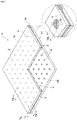
- a glass panel P includes a pair of glass plates 1A, 1B opposed to each other, a gap V formed by a plurality of columnar spacers 2 being provided at a constant spacer pitch Pd in a matrix form between the pair of glass plates 1A, 1B, a periphery sealing metal material 3 sealing a peripheral portion V1 of the gap V, and a suction hole 4 penetrating one glass plate 1A of the pair of glass plates 1A, 1B.
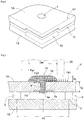
- the suction hole 4 is sealed by a suction hole sealing metal material 15 covering the suction hole 4 including a surrounding area thereof.
- the two glass plates 1A, 1B are transparent float glass, and the gap V is depressurized to 1.33 Pa (1.0 ⁇ 10 -2 Torr) or lower.
- the gap V is depressurized by discharging the inside air through the suction hole 4, and is sealed by the periphery sealing metal material 3 and the suction hole sealing metal material 15 in order to maintain the depressurized state of the gap V.
- Each spacer 2 has a columnar shape, and has a diameter of approximately 0.3 to 1.0 mm and a height of approximately 30 ⁇ m to 1.0 mm.
- the spacer 2 is made from a material that does not buckle even when being subjected to compressive stress due to the atmospheric pressure applied to the glass plates 1A, 1B, e.g., a material having a compressive strength of 4.9 ⁇ 10 8 Pa (5 ⁇ 10 3 kgf/cm 2 ) or greater, and preferably, stainless steel (SUS304) or the like.
- FIG. 3 is a flowchart showing a method for manufacturing the glass panel P shown in FIG. 1 .
- two glass raw plates made from float glass and having a predetermined thickness are each cut in predetermined dimensions, e.g., 1200 mm ⁇ 900 mm, to prepare the glass plates 1A, 1B having the same shape and the same size (step S31), and the glass plate 1A is perforated in the vicinity of one of the four corners thereof by a drill or the like, to form the suction hole 4 (step S32) (perforation step).
- predetermined dimensions e.g., 1200 mm ⁇ 900 mm
- the pair of glass plates 1A, 1B are cleaned using at least one of pure water brush cleaning, a liquid cleaning method, and optical cleaning (step S33) (cleaning step).
- a cleaning liquid contains an alkaline detergent or ozone water, for example.
- the cleaning liquid may contain a polishing agent.
- the polishing agent for example, fine particles containing cerium oxide as a main component are used.
- a plurality of spacers 2 are arranged at a constant spacer pitch Pd in a matrix form, and the cleaned glass plate 1A is overlaid thereon, whereby the glass plates 1A, 1B are paired (step S34).
- the peripheral portion V1 of the pair of glass plates 1A, 1B is sealed using the periphery sealing metal material 3 having a melting temperature of 250°C or lower (step S35) (periphery sealing).
- FIG. 4 is a view used for explaining the periphery sealing in step S35 in FIG. 3 .
- a metal introduction device 5 has a surface plate 6 having a high portion 6a and a low portion 6b lower than the high portion 6a so as to be formed in a step shape.
- the pair of glass plates 1A, 1B are retained on the high portion 6a, and a supply tower 7 for supplying solder to the pair of glass plates 1A, 1B is retained on the low portion 6b.
- the supply tower 7 includes a crucible portion 9 which stores solder in liquid phase or solid phase and has a rectangular cross-section, an electric heater 10 which is provided inside a side wall portion of the crucible portion 9 and heats solder stored in the crucible portion 9, an introduction path 11 which has an elongated sectional shape and which communicates with a bottom portion of the crucible portion 7 and opens toward an outer side of the peripheral portion V1 of the pair of glass plates 1A, 1B, and an introduction plate 8 provided horizontally at a middle level in the introduction path 11.
- the introduction plate 8 extends from the introduction path 11, to be inserted into the peripheral portion V1 of the pair of glass plates 1A, 1B.
- solder moves into the gap V with the aid of the surface tension thereof.
- the weight of solder at a liquid level ⁇ H in the crucible portion 9 is applied to solder at the introduction plate 8 part, thereby promoting the solder to move into the peripheral portion V1 of the pair of glass plates 1A, 1B.
- the introduction plate 8 may have such a shape that bent portions 8A each waved up and down a plurality of times along the movement direction thereof are formed at two locations with a space therebetween (bellows shape).
- the bent portions 8A having a spring effect slightly rubs the surface of the glass plates, so that adhesion of solder to the glass surfaces is enhanced, thus providing an effect of reliably ensuring airtightness of the gap V.
- the introduction plate 8 may have a bow shape providing a spring effect, or may have a planar shape having no bent portions. However, for the above reason, the introduction plate 8 having the bent portions 8A is more advantageous.
- the movement mechanism 13 moves at a constant speed on the rail members 12 along the peripheral portion V1 of the pair of glass plates 1A, 1B. Therefore, with the introduction plate 8 inserted into the gap V from an opened end part 14 of the pair of glass plates 1A, 1B, the periphery sealing metal material 3 moves into the entire area of the peripheral portion V1 of the pair of glass plates 1A, 1B via the introduction plate 8. Thus, the peripheral portion V1 of the gap V formed between the pair of glass plates 1A, 1B is sealed in an airtight state by the periphery sealing metal material 3.
- the opened end part 14 is provided at a corner of the glass panel P, and is formed by chamfering gap-V-side corner portions of the pair of glass plates 1A, 1B so as to facilitate insertion of the introduction plate 8 into the gap V.
- step S36 in the vicinity of the suction hole 4, an exhaust cup is attached to the atmospheric-side main surface of the glass plate 1A so as to cover the suction hole 4, and vacuuming is performed in which gas molecules in the gap V are discharged to outside so as to reduce the pressure of the gap V to 1.33 Pa or lower through suction by a rotary pump or a turbomolecular pump (not shown) connected to the exhaust cup (step S36).
- the pump used in this step is not limited to the above-described rotary pump or turbomolecular pump, but may be any pump that can be connected to the exhaust cup and can perform suction.
- the suction hole sealing metal material 15 is dropped so as to overlay the suction hole 4, whereby the glass surface in the vicinity of the suction hole 4 and the suction hole sealing metal material 15 are adhered to each other to make sealing (step S37).
- step S33 the steps from cleaning of the main surfaces of the pair of glass plates 1A, 1B (step S33) to sealing by adhering the glass surface in the vicinity of the suction hole 4 and the suction hole sealing metal material 15 (step S37) are each performed in a space in which the contamination state of the air can be chemically or physically controlled.
- the pair of glass plates 1A, 1B are cleaned using the liquid cleaning method.
- the pair of glass plates 1A, 1B may be cleaned using at least one of a pure water brush cleaning method, an ultrasonic cleaning method, an alkaline water cleaning method, a heating cleaning method, a vacuum (frozen) cleaning method, a UV cleaning method, an ozone cleaning method, and a plasma cleaning method.
- solder having a melting temperature of 250°C or lower e.g., solder obtained by adding Ti to solder having a composition of 91.2Sn-8.8Zn (eutectic temperature: 198°C) is used to seal the peripheral portion V1 of the pair of glass plates 1A, 1B.
- the periphery sealing metal material 3 solder
- the peripheral portion V1 of the pair of glass plates 1A, 1B may be sealed using a sealing material that has a melting temperature of 250°C or lower and that is a metal material including at least one material selected from a group consisting of Sn, Cu, In, Bi, Zn, Pb, Sb, Ga, and Ag.
- the periphery sealing metal material 3 may include, instead of Ti or in addition to Ti, at least one material selected from a group consisting of Al, Cr, and Si. This can improve adhesion between the periphery sealing metal material 3 and the glass component of the pair of glass plates 1A, 1B.
- the suction hole sealing metal material 15 solder having a melting temperature of 250°C or lower, e.g., solder obtained by adding Ti to solder having a composition of 91.2Sn-8.8Zn (eutectic temperature: 198°C) is used to seal the suction hole 4.
- the suction hole sealing metal material 15 solder
- the suction hole 4 may be sealed using a sealing material that has a melting temperature of 250°C or lower and that is a metal material including at least one material selected from a group consisting of Sn, Cu, In, Bi, Zn, Pb, Sb, Ga, and Ag.
- suction hole sealing metal material 15 may include, instead of Ti or in addition to Ti, at least one material selected from a group consisting of Al, Cr, and Si.
- suction hole sealing metal material 15 solder having a component different from the periphery sealing metal material 3 may be used.
- the pressure of the gap V is reduced to 1.33 Pa or lower.
- the pressure of the gap V may be reduced to reach almost a vacuum. This can further enhance thermal insulation performance of the glass panel P.
- the lower limit of a thickness Tg of each of the pair of glass plates is 0.3 mm or greater.
- the lower limit is preferably 0.5 mm or greater.
- the lower limit is 1 mm or greater. If the thickness Tg of each of the pair of glass plates is small, the heat storage capacity of the glass itself becomes small. Therefore, at the time of periphery sealing, the amount of heat dissipation to the air per unit time increases, so that the periphery sealing metal material 3 is more readily cooled. Thus, solidification of the melted periphery sealing metal material 3 can be promoted.
- the upper limit of the thickness Tg of each of the pair of glass plates is 15 mm or less.
- the upper limit is 12 mm or less.
- the upper limit is 10 mm or less.
- rigidity of the glass plate increases, and thus the amount of deformation of the glass plate due to the same magnitude of external force decreases. Therefore, in the glass panel P, tensile stress occurring in the vicinity of a gap-side surface of the suction hole 4 reduces, and thus long-term durability is improved.
- the glass plate thickness Tg increases, the amount of the suction hole sealing metal material 15 flowing into the suction hole 4 at the time of sealing the suction hole is decreased. Thus, protrusion of the suction hole sealing metal material 15 on the gap side is reduced, so that it becomes difficult to relax tensile stress occurring in the vicinity of the gap-side surface of the suction hole 4.
- the pair of glass plates 1A, 1B are float glass, but are not limited thereto.
- various types of glass such as figured glass, frosted glass having a light diffusing function due to surface treatment, wire mesh glass, a wire glass plate, tempered glass, double-tempered glass, low-reflection glass, high-transmission glass plate, a ceramic glass plate, special glass having a function of absorbing heat rays or ultraviolet rays, or a combination thereof, can be appropriately selected and used as the pair of glass plates 1A, 1B.
- composition of the pair of glass plates 1A, 1B soda silicate glass, soda-lime glass, borosilicate glass, aluminosilicate glass, various crystallized glasses, or the like can be used.
- the opened end part 14 is formed by chamfering gap-V-side corner portions of the glass plates 1A, 1B in a planar shape.
- any shape that allows the introduction plate 8 to be easily inserted e.g., curved-surface chamfers, can be appropriately selected and provided to the glass plates 1A, 1B.
- the spacer pitch Pd is 5 to 100 mm, preferably 5 to 80 mm, and further preferably 5 to 60 mm.
- the spacer 2 is formed from stainless steel, but is not limited thereto.
- the spacer 2 may be formed from a high-rigidity material, e.g., Inconel, metal such as iron, aluminum, tungsten, nickel, chromium, or titanium, an alloy such as carbon steel, chrome steel, nickel steel, nickel chrome steel, manganese steel, chrome manganese steel, chrome molybdenum steel, silicon steel, brass, solder, or duralumin, ceramic, glass, etc.
- the shape of the spacer 2 is not limited to a columnar shape, but may be various shapes such as an angled shape or a spherical shape.
- a gap height Vh is 30 ⁇ m to 1 mm. It is noted that the gap height Vh is substantially the same as the height of the spacer 2.
- an evaporable getter may be used for adsorbing gas molecules in the gap V
- a non-evaporable getter which adsorbs and removes gas molecules by being heated and activated may be used, or a non-evaporable getter and an evaporable getter may be used in combination.
- getter materials (adsorbents) and adsorbent storage holes may be provided at two or more locations.
- the periphery sealing metal material 3 is formed using the metal introduction device 5, but another method may be used.
- the periphery sealing metal material 3 may be formed using at least one joining method of anodic bonding, ultrasonic welding, multistage welding, laser welding, and pressure bonding.
- adhesion of the periphery sealing metal material 3 to the pair of glass plates 1A, 1B can be improved.
- a width Rw of the periphery sealing metal material 3 as seen in the thickness direction with respect to the plane of the glass panel P is not less than 1 mm and not greater than 10 mm. If the width Rw is less than 1 mm, it is difficult to keep the sealing of the gap V of the glass panel P. In addition, if the width Rw is greater than 10 mm, the amount of heat exchange occurring through the periphery sealing metal material 3 becomes excessive. Further preferably, the width Rw is not less than 1 mm and not greater than 5 mm. In this case, it is possible to keep the sealing of the gap V of the glass panel P and in addition, reduce the amount of heat exchange.
- a part of the suction hole sealing metal material 15 that protrudes from the atmospheric-side surface of the glass plate 1A after sealing is referred to as a protruding portion 16.
- a protruding portion diameter Dw (which is the same as the width of a contact portion 33 in contact with the glass plate 1A in FIG. 1 ) of the protruding portion 16 is 2 to 30 mm. Further preferably, the protruding portion diameter Dw is 2 to 15 mm. It is noted that, in any case, the protruding portion diameter Dw is greater than a suction hole diameter Sw.
- a protruding portion thickness Dg of the protruding portion 16 is 0.1 to 20 mm.
- the protruding portion thickness Dg is 0.1 to 10 mm.
- the suction hole diameter Sw is 2 to 10 mm.
- the suction hole diameter Sw is 2 to 5 mm.
- it is desirable that the suction hole diameter Sw is greater than the glass thickness and is not greater than 10 mm. This is for passing air through the suction hole 4 at the time of air-quenching tempering.
- At least a lower edge portion of the suction hole 4 may be formed in a curved-surface shape or may be chamfered (a minute surface may be provided at the edge portion).
- the suction hole sealing metal material 15 drops due to the own weight through the inside of the guide cylinder 20, by a mass of solder provided at an upper part of a supply port, a heater for heating and melting the solder, and a dropping device for dropping the melted suction hole sealing metal material 15.
- the melted suction hole sealing metal material 15 spreads on the atmospheric-side surface of the glass plate 1A to form the protruding portion 16 along the inner circumference of the guide cylinder 20.
- solder contraction stress Fa1 occurs due to cooling.
- the thermal expansion coefficient (e.g., in the case of float glass, generally 8 to 9 ⁇ 10 -6 /°C (ordinary temperature to 350°C)) of the glass plate 1A is smaller than the thermal expansion coefficient (e.g., in the present embodiment, 24 ⁇ 10 -6 /°C; in the case of normal solder, approximately 15 ⁇ 10 -6 /°C to 30 ⁇ 10 -6 /°C) of the suction hole sealing metal material 15. Therefore, upper part compressive stress Fa2 occurs.
- a reaction force to the upper part compressive stress Fa2 occurs as first tensile stress Fa (shearing force) in the vicinity of an edge 4e of the suction hole 4 on the gap side.
- a temperature range of 180°C to 250°C which is the melting temperature of general tin (Sn) solder, or a thermal expansion coefficient of 15 to 30 ⁇ 10 -6 /°C, is applicable.
- the spacers 2 are arranged at constant intervals Pd (spacer pitch) in a matrix form along the planes of the pair of glass and plates 1A, 1B.
- the spacers 2 form the gap V and hamper heat conduction between the pair of glass plates 1A, 1B.
- An atmospheric pressure Fb1 is applied to the glass plates 1A, 1B supported by the spacers 2, so that second tensile stress Fb occurs on the gap V side of the glass plate 1A.
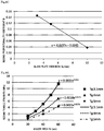
- FIGS. 8A to 8C are graphs made on the basis of a result of experiment conducted using suction hole sealing metal materials 15 having protruding portion diameters Dw of 8, 10, 12 mm, and numerical values derived from the result.
- the first proportionality coefficient A is determined by the protruding portion diameter Dw.
- FIG. 8B is a graph obtained by plotting values of the protruding portion diameter Dw and values of the first proportionality coefficient A corresponding thereto. Further, these plotted points are grouped on the basis of the glass plate thickness Tg, and an approximation linear line is added for each group. From this graph, the first proportionality coefficient A is proportional to the protruding portion diameter Dw, and the relationship therebetween can be represented by the following expression.
- A B ⁇ Dw
- the second proportionality coefficient B is determined by the glass plate thickness Tg.
- FIG. 8C is a graph obtained by plotting values of the glass plate thickness Tg and values of the second proportionality coefficient B corresponding thereto, and adding an approximation linear line. From this graph, the second proportionality coefficient B is proportional to the glass plate thickness Tg, and the relationship therebetween can be represented by the following expression.
- B ⁇ 0.0157 Tg + 0.1945
- B second proportionality coefficient
- Tg glass plate thickness (mm)
- the first tensile stress Fa is represented by the following Expression (1a).
- Fa ⁇ 0.0157 Tg + 0.1945 ⁇ Dw ⁇ Dg Tg: glass plate thickness (mm), Dw: protruding portion diameter (mm) of suction hole sealing metal material 15, Dg: protruding portion thickness (mm) of suction hole sealing metal material 15
- FIGS. 9A and 9B show a result of simulation (nonlinear analysis using finite element method analysis software (Abaqus Ver6.11)) conducted by the present inventors for three cases with different glass plate thicknesses Tg, regarding the second tensile stress Fb. It is noted that the used glass plate thicknesses Tg (mm) were 3.1, 4, and 5.
- C is the proportionality coefficient (third proportionality coefficient) in Expression (1b-1).
- the third proportionality coefficient C is determined by the glass plate thickness Tg.
- the second tensile stress Fb is represented by the following Expression (1b).
- Fb 0.0361 Pd 2 / Tg 2.2
- Fb second tensile stress
- Pd spacer pitch (interval, mm)
- Tg glass plate thickness (mm)
- the long-term permissible stress Fc at the edge portion of the glass plate is set to 7 MPa as described above.
- Fc is uniquely determined by the material, and Tg is determined from the specifications.
- Pd is desired to be great, and is determined from the heat insulation specifications of the glass panel. Thus, it is difficult to control these elements. Therefore, by controlling the protruding portion thickness Dg and the diameter Dw, it is possible to prevent breakage of glass beforehand.
- float glass is used and the long-term permissible stress Fc at the edge portion of the glass plate is 7 MPa.
- Fc in the case of using tempered glass, it is possible to set Fc to 69 MPa at maximum.
- Fc can be adjusted in a range of 7 to 69 MPa. It is noted that, even with a numerical range including these values of Fc (in the case of float glass, Fc: 5 to 15 MPa; in the case of tempered glass, 50 to 80 MPa), the effects of the invention of the present application can be provided.
- the present invention is applicable as a glass panel having high thermal insulation performance.
- the present invention is applicable as a thermal insulation glass panel required to have long-term durability for a door, a wall part, etc., of a building or a vehicle (window glass of an automobile, a rail road vehicle, a vessel, etc.) or of various devices such as a refrigerator and a heat insulating device.
Landscapes
- Engineering & Computer Science (AREA)
- Chemical & Material Sciences (AREA)
- Civil Engineering (AREA)
- Structural Engineering (AREA)
- Chemical Kinetics & Catalysis (AREA)
- Life Sciences & Earth Sciences (AREA)
- Ceramic Engineering (AREA)
- General Chemical & Material Sciences (AREA)
- Geochemistry & Mineralogy (AREA)
- Materials Engineering (AREA)
- Organic Chemistry (AREA)
- Joining Of Glass To Other Materials (AREA)
- Securing Of Glass Panes Or The Like (AREA)
Abstract

Description
- The present invention relates to a glass panel including: a pair of glass plates; a gap formed by the pair of glass plates being disposed so as to be opposed to each other with a spacer interposed between the pair of glass plates; and a periphery sealing metal material joining the pair of glass plates at a peripheral portion thereof so as to make the gap airtight, wherein one glass plate of the pair of glass plates has a suction hole penetrating the one glass plate in a front-back direction thereof, and air in the gap is sucked so as to depressurize the gap, and the suction hole is sealed by a suction hole sealing metal material having a thermal expansion coefficient different from that of the pair of glass plates.
- Conventionally, in such a glass panel as described above, some consideration has been made on pillar arrangement and the like, but no particular consideration has been made on strength calculation around the suction hole (see, for example, Patent Document 1). Meanwhile, various methods are used for sealing around the suction hole, but no particular consideration has been made on strength calculation around the suction hole (see, for example, Patent Document 2).
- Incidentally, the present inventors have adopted, for sealing the suction hole, a method of, for example, dropping a suction hole sealing metal material from above the suction hole and thereby solidifying the suction hole sealing metal material, to keep the airtight state. The thermal expansion coefficient of the suction hole sealing metal material is greater than that of the glass plate, and therefore, it has been found that, by a reaction force due to thermal contraction of the suction hole sealing metal material, tensile stress occurs as internal stress around the suction hole on the gap side. In addition, when the gap between the glass plates is depressurized, the atmospheric pressure also causes tensile stress as internal stress around the suction hole on the gap side.
-
- [PATENT DOCUMENT 1] Japanese Laid-Open Patent Publication No.
H09-268035 - [PATENT DOCUMENT 2] Japanese Laid-Open Patent Publication No.
2002-137940 - Accordingly, an object of the present invention is to solve a strength problem around a suction hole on the gap side due to internal stress caused by a suction hole sealing metal material and depressurization, and provide a glass panel having enhanced safety.
- In order to attain the above object, a glass panel according to the present invention includes: a pair of glass plates; a gap formed by the pair of glass plates being disposed so as to be opposed to each other with a spacer interposed between the pair of glass plates; and a periphery sealing metal material joining the pair of glass plates at a peripheral portion thereof so as to make the gap airtight, wherein one glass plate of the pair of glass plates has a suction hole penetrating the one glass plate in a front-back direction thereof, air in the gap is sucked so as to depressurize the gap and the suction hole is sealed by a suction hole sealing metal material having a thermal expansion coefficient different from that of the pair of glass plates, the suction hole sealing metal material keeps an airtight state on the suction hole, the suction hole sealing metal material is formed concentrically with the suction hole in plan view, and the following Expression (1) is satisfied:

- Here, according to experiment by the present inventors, first tensile stress Fa occurring in the suction hole sealing metal material and second tensile stress Fb occurring on the gap side around the suction hole due to depressurization are represented by the following Expressions (1a), (1b), respectively.


- The sum of the first tensile stress Fa and the second tensile stress Fb needs to be smaller than long-term permissible stress at the glass edge, and thus Expression (1) is obtained using Expressions (1a), (1b).
- With the above Expression (1), the protruding portion diameter Dw is appropriately adjusted so that the sum of the first tensile stress Fa and the second tensile stress Fb is kept smaller than the long-term permissible stress Fc at the glass edge, whereby breakage of the glass due to stress concentration can be prevented.
- Further, in the above configuration, it is desirable that the protruding portion diameter Dw of the suction hole sealing metal material is fixed, and is set so as to satisfy the following Expression (2):

- Thus, the protruding portion thickness Dg is appropriately adjusted, whereby, as in the above, breakage of the glass due to stress concentration can be prevented.
- Further, in addition to each of the above configurations, it is desirable that first tensile stress Fa is set so as to satisfy the following Expression (3):

- According to P. 16 of the recommended standards by Flat Glass Manufacturers Association of Japan (issued in August, 2003), the long-term permissible stress Fc at the glass edge in the case of float glass is 7 MPa (6.9 MPa rounded off). In addition, according to calculation by the present inventors in embodiments, the second tensile stress Fb is 2 MPa. Therefore, 7 MPa-2 MPa=5 MPa is obtained, so that the above Expression (3) is satisfied.
- Further, in addition to each of the above configurations, it is desirable that first tensile stress Fa is set so as to satisfy the following Expression (4):

- This is obtained as a result of setting the safety factor to less than 2 and considering variation in stress.
- Further, in the above configurations, the suction hole sealing
metal material 15 may be solidified by being dropped from above the suction hole, to keep the airtight state. - With this configuration, the suction hole sealing
metal material 15 closely adheres to the glass surface, and further can flow into thesuction hole 4. - From the above relationships, depending on the settings of the glass plate thickness Tg, the pillar interval Pd, and the diameter Dw and the thickness Dg of the protruding
portion 16, a risk of damage due to internal stress around thesuction hole 4 can be reduced. - Further, in each of the above configurations, the spacer may be composed of a plurality of pillars interposed in a matrix form at a predetermined pitch Pd so as to keep a predetermined interval between the pair of glass plates, and the pillars may be arranged at a narrower pitch in a vicinity of the suction hole than a pitch at another part.
- With this configuration, the pillar interval is narrowed, whereby the second tensile stress Fb occurring on the gap side around the suction hole due to the depressurization is reduced.
- For the same reason, the spacer may be composed of a plurality of pillars interposed in a matrix form at a predetermined pitch so as to keep a predetermined interval between the pair of glass plates, and at least one other pillar different from the plurality of pillars may be provided closer to the suction hole than the plurality of pillars.
- Further, in addition to each of the above configurations, it is desirable that a width of the periphery sealing metal material as seen in a thickness direction with respect to a plane of the glass panel is 1 to 10 mm.
- Further, in addition to each of the above configurations, it is desirable that a thickness of at least one of the pair of glass plates is 0.3 to 15 mm.
- Further, in addition to each of the above configurations, it is desirable that a width of the protruding portion is 2 to 30 mm.
- Further, in addition to each of the above configurations, it is desirable that a thickness of the protruding portion is 0.1 to 20 mm.
- Further, in addition to each of the above configurations, it is desirable that a pitch of the spacer is 5 to 100 mm.
- Further, in addition to each of the above configurations, it is desirable that a diameter of the suction hole is 2 to 10 mm.
- Further, in addition to each of the above configurations, it is desirable that at least a gap-side edge portion of the suction hole is formed in a curved-surface shape or is chamfered.
- Thus, the above configurations of the glass panel according to the present invention make it possible to solve a strength problem around the suction hole on the gap side due to internal stress caused by the suction hole sealing metal material and depressurization, and provide the glass panel having enhanced safety.
- Other objects, configurations, and effects of the present invention will become apparent from the description of embodiments of the present invention shown below.
-
- [
FIG. 1] FIG. 1 is a partially cutaway perspective view of a glass panel. - [
FIG. 2] FIG. 2 is a vertical sectional view around a suction hole of the glass panel. - [
FIG. 3] FIG. 3 is a flowchart showing a method for manufacturing the glass panel. - [
FIG. 4] FIG. 4 is a major part vertical sectional view showing a periphery sealing step. - [
FIG. 5] FIG. 5 illustrates an action of an introduction plate. - [
FIG. 6] FIG. 6 is an enlarged view around the suction hole before sealing of the suction hole. - [
FIG. 7] FIG. 7 is an enlarged vertical sectional view around the suction hole of the glass panel. - [
FIG. 8A] FIG. 8A is a graph showing the correlation between a protruding portion thickness Dg and first tensile stress Fa in experiment regarding first tensile stress Fa. - [
FIG. 8B] FIG. 8B is a graph showing the correlation between a protruding portion diameter Dw and a first proportionality coefficient A in experiment regarding first tensile stress Fa. - [
FIG. 8C] FIG. 8C is a graph showing the correlation between a glass plate thickness Tg and a second proportionality coefficient B in experiment regarding first tensile stress Fa. - [
FIG. 9A] FIG. 9A is a graph showing the correlation between a spacer pitch Pd and second tensile stress Fb in simulation regarding second tensile stress Fb. - [
FIG. 9B] FIG. 9B is a graph showing the correlation between the glass plate thickness Tg and a third proportionality coefficient C in simulation regarding second tensile stress Fb. - [
FIG. 10] FIG. 10 is a plan view showing another embodiment of a glass panel. - [
FIG. 11] FIG. 11 is a partial enlarged sectional view ofFIG. 7 . - Hereinafter, embodiments of the present invention will be described with reference to the drawings.
- In
FIG. 1 , a glass panel P includes a pair ofglass plates columnar spacers 2 being provided at a constant spacer pitch Pd in a matrix form between the pair ofglass plates metal material 3 sealing a peripheral portion V1 of the gap V, and asuction hole 4 penetrating oneglass plate 1A of the pair ofglass plates suction hole 4 is sealed by a suction hole sealingmetal material 15 covering thesuction hole 4 including a surrounding area thereof. - In the glass panel P, the two
glass plates suction hole 4, and is sealed by the periphery sealingmetal material 3 and the suction hole sealingmetal material 15 in order to maintain the depressurized state of the gap V. - Each
spacer 2 has a columnar shape, and has a diameter of approximately 0.3 to 1.0 mm and a height of approximately 30 µm to 1.0 mm. Thespacer 2 is made from a material that does not buckle even when being subjected to compressive stress due to the atmospheric pressure applied to theglass plates -
FIG. 3 is a flowchart showing a method for manufacturing the glass panel P shown inFIG. 1 . - First, two glass raw plates (not shown) made from float glass and having a predetermined thickness are each cut in predetermined dimensions, e.g., 1200 mm × 900 mm, to prepare the
glass plates glass plate 1A is perforated in the vicinity of one of the four corners thereof by a drill or the like, to form the suction hole 4 (step S32) (perforation step). - Next, in a space such as a clean room or a chemical clean room in which the contamination state of air can be chemically or physically controlled, the pair of
glass plates - On the
glass plate 1B which has nosuction hole 4 and has been cleaned, a plurality ofspacers 2 are arranged at a constant spacer pitch Pd in a matrix form, and the cleanedglass plate 1A is overlaid thereon, whereby theglass plates - Further, while the paired
glass plates glass plates metal material 3 having a melting temperature of 250°C or lower (step S35) (periphery sealing). -
FIG. 4 is a view used for explaining the periphery sealing in step S35 inFIG. 3 . - In
FIG. 4 , ametal introduction device 5 has asurface plate 6 having ahigh portion 6a and alow portion 6b lower than thehigh portion 6a so as to be formed in a step shape. The pair ofglass plates high portion 6a, and asupply tower 7 for supplying solder to the pair ofglass plates low portion 6b. On thelow portion 6b of the steppedsurface plate 6, tworail members 12 are arranged along the pair ofglass plates supply tower 7 is placed on amovement mechanism 13 which moves on therail members 12. - The
supply tower 7 includes acrucible portion 9 which stores solder in liquid phase or solid phase and has a rectangular cross-section, anelectric heater 10 which is provided inside a side wall portion of thecrucible portion 9 and heats solder stored in thecrucible portion 9, anintroduction path 11 which has an elongated sectional shape and which communicates with a bottom portion of thecrucible portion 7 and opens toward an outer side of the peripheral portion V1 of the pair ofglass plates introduction plate 8 provided horizontally at a middle level in theintroduction path 11. Theintroduction plate 8 extends from theintroduction path 11, to be inserted into the peripheral portion V1 of the pair ofglass plates crucible portion 9 is applied to solder at theintroduction plate 8 part, thereby promoting the solder to move into the peripheral portion V1 of the pair ofglass plates - In addition, as shown in
FIG. 5 , theintroduction plate 8 may have such a shape that bentportions 8A each waved up and down a plurality of times along the movement direction thereof are formed at two locations with a space therebetween (bellows shape). - That is, when the
introduction plate 8 having thebent portions 8A moves, thebent portions 8A having a spring effect slightly rubs the surface of the glass plates, so that adhesion of solder to the glass surfaces is enhanced, thus providing an effect of reliably ensuring airtightness of the gap V. - In addition, the
introduction plate 8 may have a bow shape providing a spring effect, or may have a planar shape having no bent portions. However, for the above reason, theintroduction plate 8 having thebent portions 8A is more advantageous. - Meanwhile, the
movement mechanism 13 moves at a constant speed on therail members 12 along the peripheral portion V1 of the pair ofglass plates introduction plate 8 inserted into the gap V from an openedend part 14 of the pair ofglass plates metal material 3 moves into the entire area of the peripheral portion V1 of the pair ofglass plates introduction plate 8. Thus, the peripheral portion V1 of the gap V formed between the pair ofglass plates metal material 3. - As shown in
FIG. 6 , the openedend part 14 is provided at a corner of the glass panel P, and is formed by chamfering gap-V-side corner portions of the pair ofglass plates introduction plate 8 into the gap V. - In subsequent step S36, in the vicinity of the
suction hole 4, an exhaust cup is attached to the atmospheric-side main surface of theglass plate 1A so as to cover thesuction hole 4, and vacuuming is performed in which gas molecules in the gap V are discharged to outside so as to reduce the pressure of the gap V to 1.33 Pa or lower through suction by a rotary pump or a turbomolecular pump (not shown) connected to the exhaust cup (step S36). - It is noted that the pump used in this step is not limited to the above-described rotary pump or turbomolecular pump, but may be any pump that can be connected to the exhaust cup and can perform suction.
- Next, the suction hole sealing
metal material 15 is dropped so as to overlay thesuction hole 4, whereby the glass surface in the vicinity of thesuction hole 4 and the suction hole sealingmetal material 15 are adhered to each other to make sealing (step S37). - Thus, the gap V formed between the pair of
glass plates - It is noted that, among the above steps, the steps from cleaning of the main surfaces of the pair of
glass plates suction hole 4 and the suction hole sealing metal material 15 (step S37) are each performed in a space in which the contamination state of the air can be chemically or physically controlled. - In the present embodiment, the pair of
glass plates glass plates glass plates - In the present embodiment, as the periphery sealing
metal material 3, solder having a melting temperature of 250°C or lower, e.g., solder obtained by adding Ti to solder having a composition of 91.2Sn-8.8Zn (eutectic temperature: 198°C) is used to seal the peripheral portion V1 of the pair ofglass plates glass plates - In addition, the periphery sealing
metal material 3 may include, instead of Ti or in addition to Ti, at least one material selected from a group consisting of Al, Cr, and Si. This can improve adhesion between the periphery sealingmetal material 3 and the glass component of the pair ofglass plates - In the present embodiment, as the suction hole sealing
metal material 15, solder having a melting temperature of 250°C or lower, e.g., solder obtained by adding Ti to solder having a composition of 91.2Sn-8.8Zn (eutectic temperature: 198°C) is used to seal thesuction hole 4. However, the suction hole sealing metal material 15 (solder) is not limited thereto. Thesuction hole 4 may be sealed using a sealing material that has a melting temperature of 250°C or lower and that is a metal material including at least one material selected from a group consisting of Sn, Cu, In, Bi, Zn, Pb, Sb, Ga, and Ag. - It is noted that, in the case of selecting Sn, it suffices that the amount thereof is 90% or higher, and in the case of Sn with Cu added thereto, the amount of Cu needs to be 0.1% or lower.
- In addition, the suction hole sealing
metal material 15 may include, instead of Ti or in addition to Ti, at least one material selected from a group consisting of Al, Cr, and Si. - Further, as the suction hole sealing
metal material 15, solder having a component different from the periphery sealingmetal material 3 may be used. - It is noted that containing Ti (titanium) in the suction hole sealing
metal material 15 or the periphery sealingmetal material 3 improves close adhesion to glass. - In the present embodiment, the pressure of the gap V is reduced to 1.33 Pa or lower. However, without limitation thereto, the pressure of the gap V may be reduced to reach almost a vacuum. This can further enhance thermal insulation performance of the glass panel P.
- In the present embodiment, the lower limit of a thickness Tg of each of the pair of glass plates is 0.3 mm or greater. In addition, the lower limit is preferably 0.5 mm or greater. Further preferably, the lower limit is 1 mm or greater. If the thickness Tg of each of the pair of glass plates is small, the heat storage capacity of the glass itself becomes small. Therefore, at the time of periphery sealing, the amount of heat dissipation to the air per unit time increases, so that the periphery sealing
metal material 3 is more readily cooled. Thus, solidification of the melted periphery sealingmetal material 3 can be promoted. However, if the glass plate is thinned, rigidity of the glass plate reduces, and thus the amount of deformation of the glass plate due to the same magnitude of external force increases. Therefore, in the glass panel P, tensile stress occurring in the vicinity of a gap-side surface of thesuction hole 4 increases. - The upper limit of the thickness Tg of each of the pair of glass plates is 15 mm or less. Preferably, the upper limit is 12 mm or less. Further preferably, the upper limit is 10 mm or less. In the case of using a thick glass plate, rigidity of the glass plate increases, and thus the amount of deformation of the glass plate due to the same magnitude of external force decreases. Therefore, in the glass panel P, tensile stress occurring in the vicinity of a gap-side surface of the
suction hole 4 reduces, and thus long-term durability is improved. On the other hand, if the glass plate thickness Tg increases, the amount of the suction hole sealingmetal material 15 flowing into thesuction hole 4 at the time of sealing the suction hole is decreased. Thus, protrusion of the suction hole sealingmetal material 15 on the gap side is reduced, so that it becomes difficult to relax tensile stress occurring in the vicinity of the gap-side surface of thesuction hole 4. - The pair of
glass plates glass plates - Further, also regarding the composition of the pair of
glass plates - In the present embodiment, the opened
end part 14 is formed by chamfering gap-V-side corner portions of theglass plates introduction plate 8 to be easily inserted, e.g., curved-surface chamfers, can be appropriately selected and provided to theglass plates - In the present embodiment, the spacer pitch Pd is 5 to 100 mm, preferably 5 to 80 mm, and further preferably 5 to 60 mm.
- In addition, the
spacer 2 is formed from stainless steel, but is not limited thereto. Thespacer 2 may be formed from a high-rigidity material, e.g., Inconel, metal such as iron, aluminum, tungsten, nickel, chromium, or titanium, an alloy such as carbon steel, chrome steel, nickel steel, nickel chrome steel, manganese steel, chrome manganese steel, chrome molybdenum steel, silicon steel, brass, solder, or duralumin, ceramic, glass, etc. In addition, the shape of thespacer 2 is not limited to a columnar shape, but may be various shapes such as an angled shape or a spherical shape. - In the present embodiment, a gap height Vh is 30 µm to 1 mm. It is noted that the gap height Vh is substantially the same as the height of the
spacer 2. - It is noted that, in the gap V, an evaporable getter may be used for adsorbing gas molecules in the gap V, a non-evaporable getter which adsorbs and removes gas molecules by being heated and activated may be used, or a non-evaporable getter and an evaporable getter may be used in combination. In addition, in the gap V, getter materials (adsorbents) and adsorbent storage holes may be provided at two or more locations.
- In the present embodiment, the periphery sealing
metal material 3 is formed using themetal introduction device 5, but another method may be used. The periphery sealingmetal material 3 may be formed using at least one joining method of anodic bonding, ultrasonic welding, multistage welding, laser welding, and pressure bonding. Thus, adhesion of the periphery sealingmetal material 3 to the pair ofglass plates - In addition, a width Rw of the periphery sealing
metal material 3 as seen in the thickness direction with respect to the plane of the glass panel P is not less than 1 mm and not greater than 10 mm. If the width Rw is less than 1 mm, it is difficult to keep the sealing of the gap V of the glass panel P. In addition, if the width Rw is greater than 10 mm, the amount of heat exchange occurring through the periphery sealingmetal material 3 becomes excessive. Further preferably, the width Rw is not less than 1 mm and not greater than 5 mm. In this case, it is possible to keep the sealing of the gap V of the glass panel P and in addition, reduce the amount of heat exchange. - In the present embodiment, a part of the suction hole sealing
metal material 15 that protrudes from the atmospheric-side surface of theglass plate 1A after sealing is referred to as a protrudingportion 16. A protruding portion diameter Dw (which is the same as the width of acontact portion 33 in contact with theglass plate 1A inFIG. 1 ) of the protrudingportion 16 is 2 to 30 mm. Further preferably, the protruding portion diameter Dw is 2 to 15 mm. It is noted that, in any case, the protruding portion diameter Dw is greater than a suction hole diameter Sw. - In addition, a protruding portion thickness Dg of the protruding
portion 16 is 0.1 to 20 mm. Preferably, the protruding portion thickness Dg is 0.1 to 10 mm. - It is noted that the larger the contact surface between the protruding
portion 16 and theglass plate 1A is, the greater the contraction stress that occurs is. In addition, the smaller the protruding portion diameter Dw is, the greater the difficulty in accurately sealing thesuction hole 4 is. - In the present embodiment, the suction hole diameter Sw is 2 to 10 mm. Preferably, the suction hole diameter Sw is 2 to 5 mm. In the case of tempered glass, it is desirable that the suction hole diameter Sw is greater than the glass thickness and is not greater than 10 mm. This is for passing air through the
suction hole 4 at the time of air-quenching tempering. - In addition, at least a lower edge portion of the
suction hole 4 may be formed in a curved-surface shape or may be chamfered (a minute surface may be provided at the edge portion). - Hereinafter, with reference to
FIG. 7 andFIG. 11 , the relationship between sealing of the suction hole and stress will be described with reference toFIG. 7 andFIG. 11 . The suction hole sealingmetal material 15 drops due to the own weight through the inside of theguide cylinder 20, by a mass of solder provided at an upper part of a supply port, a heater for heating and melting the solder, and a dropping device for dropping the melted suction hole sealingmetal material 15. The melted suction hole sealingmetal material 15 spreads on the atmospheric-side surface of theglass plate 1A to form the protrudingportion 16 along the inner circumference of theguide cylinder 20. - In the protruding
portion 16 of the suction hole sealingmetal material 15, solder contraction stress Fa1 occurs due to cooling. However, the thermal expansion coefficient (e.g., in the case of float glass, generally 8 to 9 × 10⁻⁶/°C (ordinary temperature to 350°C)) of theglass plate 1A is smaller than the thermal expansion coefficient (e.g., in the present embodiment, 24 × 10-6/°C; in the case of normal solder, approximately 15 × 10-6/°C to 30 × 10-6/°C) of the suction hole sealingmetal material 15. Therefore, upper part compressive stress Fa2 occurs. A reaction force to the upper part compressive stress Fa2 occurs as first tensile stress Fa (shearing force) in the vicinity of anedge 4e of thesuction hole 4 on the gap side. - Incidentally, in the case of vacuum glass sealed by frit, there is no thermal expansion difference between glass and frit, and therefore, even if the sealing temperature is high (500°C), influence of stress is small. Thus, it suffices that strength designing (for glass thickness Tg and pillar interval Pd) is made in consideration of the atmospheric pressure.
- However, as compared to frit, solder has poor wettability with glass, so that a large volume of solder is needed for sealing. It has been newly found that stress occurs depending on the volume (Dg and Dw) and therefore this needs to be taken into consideration for strength designing, leading to introduction of the first tensile stress Fa.
- That is, it has been found that, in the case of performing sealing with solder at high temperature, thermal expansion difference is great and thus the sealing is impossible, but in a temperature range of 250°C or lower, the sealing can be performed.
- For example, a temperature range of 180°C to 250°C, which is the melting temperature of general tin (Sn) solder, or a thermal expansion coefficient of 15 to 30 × 10-6/°C, is applicable.
- The
spacers 2 are arranged at constant intervals Pd (spacer pitch) in a matrix form along the planes of the pair of glass andplates spacers 2 form the gap V and hamper heat conduction between the pair ofglass plates glass plates spacers 2, so that second tensile stress Fb occurs on the gap V side of theglass plate 1A. - These tensile stresses are summed as internal stress, so that stress concentration possibly occurs on the
edge 4e of thesuction hole 4 on the gap side. Therefore, the summed stress at this part needs to be not greater than long-term permissible stress (defined as Fc) in the glass edge. -
FIGS. 8A to 8C are graphs made on the basis of a result of experiment conducted using suction hole sealingmetal materials 15 having protruding portion diameters Dw of 8, 10, 12 mm, and numerical values derived from the result. -
FIG. 8A is a graph obtained by plotting values of the protruding portion thickness Dg and values of the first tensile stress Fa corresponding thereto. Further, these plotted points are grouped on the basis of the protruding portion diameter Dw, and an approximation linear line is added for each group. From this graph, the first tensile stress Fa is proportional to the protruding portion thickness Dg, and the relationship therebetween can be represented by the following expression.
- Fa: first tensile stress (MPa), Dg: protruding portion thickness (mm) of suction hole sealing
metal material 15 - Here, A is the proportionality coefficient (first proportionality coefficient) in Expression (1a-1).
- From
FIG. 8A , it is found that the first proportionality coefficient A is determined by the protruding portion diameter Dw. -
FIG. 8B is a graph obtained by plotting values of the protruding portion diameter Dw and values of the first proportionality coefficient A corresponding thereto. Further, these plotted points are grouped on the basis of the glass plate thickness Tg, and an approximation linear line is added for each group. From this graph, the first proportionality coefficient A is proportional to the protruding portion diameter Dw, and the relationship therebetween can be represented by the following expression.
- A: first proportionality coefficient, Dw: protruding portion diameter (mm) of suction hole sealing
metal material 15 - Here, B is the proportionality coefficient (second proportionality coefficient) in Expression (1a-2).
- From
FIG. 8B , it is found that the second proportionality coefficient B is determined by the glass plate thickness Tg. -
FIG. 8C is a graph obtained by plotting values of the glass plate thickness Tg and values of the second proportionality coefficient B corresponding thereto, and adding an approximation linear line. From this graph, the second proportionality coefficient B is proportional to the glass plate thickness Tg, and the relationship therebetween can be represented by the following expression.
- Thus, from
FIGS. 8A to 8C and Expressions (1a-1) to (1a-3), the first tensile stress Fa is represented by the following Expression (1a).
metal material 15, Dg: protruding portion thickness (mm) of suction hole sealingmetal material 15 - On the other hand,
FIGS. 9A and9B show a result of simulation (nonlinear analysis using finite element method analysis software (Abaqus Ver6.11)) conducted by the present inventors for three cases with different glass plate thicknesses Tg, regarding the second tensile stress Fb. It is noted that the used glass plate thicknesses Tg (mm) were 3.1, 4, and 5. -
FIG. 9A is a graph obtained by plotting values of the spacer pitch Pd and values of the second tensile stress Fb corresponding thereto. Further, the plotted points are grouped on the basis of the glass plate thickness Tg, and an approximation curved line is added for each group. From this graph, the second tensile stress Fb is determined by the value of the spacer pitch Pd, and the relationship therebetween can be represented by the following expression. It is noted that the exponent of the spacer pitch Pd is set to 2 by approximation.
- Here, C is the proportionality coefficient (third proportionality coefficient) in Expression (1b-1).
- From
FIG. 9A , it is found that the third proportionality coefficient C is determined by the glass plate thickness Tg. -
FIG. 9B is a graph obtained by plotting values of the glass plate thickness Tg and values of the third proportionality coefficient C corresponding thereto, and adding an approximation curved line thereto. From this graph, the relationship between the third proportionality coefficient C and the glass plate thickness Tg can be represented by the following expression. It is noted that the exponent of the glass plate thickness Tg is set to -2.2 by approximation.
- Thus, from
FIGS. 9A and9B and Expressions (1b-1), (1b-2), the second tensile stress Fb is represented by the following Expression (1b).
- Using the above results, the following Expressions (1), (2) are derived.


- Thus, by appropriately adjusting the protruding portion diameter Dw and the thickness Dg, it is possible to prevent breakage of the glass plate due to stress concentration.
- With further consideration added on the safety index, the long-term permissible stress Fc at the edge portion of the glass plate is set to 7 MPa as described above. In addition, when the value of stress occurring on the gap side due to the atmospheric pressure was calculated through nonlinear analysis using finite element method analysis software (Abaqus Ver6.11), the second tensile stress Fb was approximately 2 MPa. Therefore, setting is made so as to satisfy first tensile stress Fa<=5 MPa. In addition, with the safety factor set to 2 or less, and further, in consideration of variation in stress, setting may be made so as to satisfy first tensile stress Fa<=3 MPa.
- In the above expressions, Fc is uniquely determined by the material, and Tg is determined from the specifications. In view of heat insulation property, Pd is desired to be great, and is determined from the heat insulation specifications of the glass panel. Thus, it is difficult to control these elements. Therefore, by controlling the protruding portion thickness Dg and the diameter Dw, it is possible to prevent breakage of glass beforehand.
- In the present embodiment, float glass is used and the long-term permissible stress Fc at the edge portion of the glass plate is 7 MPa. However, in the case of using tempered glass, it is possible to set Fc to 69 MPa at maximum. Depending on the tempering specifications, Fc can be adjusted in a range of 7 to 69 MPa. It is noted that, even with a numerical range including these values of Fc (in the case of float glass, Fc: 5 to 15 MPa; in the case of tempered glass, 50 to 80 MPa), the effects of the invention of the present application can be provided.
- Other embodiments will be described below.
- In other embodiments below, the same members as those in the above embodiment are denoted by the same reference characters.
- (1) According to the above Expression (1b) (expression of Fb), the second tensile stress Fb is proportional to the square of the interval Pd of the pillars. Therefore, by reducing the interval of the pillars, it is possible to reduce stress concentration on the
edge 4e. On the basis of this principle, in an embodiment shown inFIG. 10 , intermediate pillars 2' are provided at positions corresponding to half the intervals of thenormal pillars 2, whereby the second tensile stress Fb is reduced. Thus, larger first tensile stress Fa is permissible, and therefore it becomes possible to make more reliable sealing by increasing the protruding portion diameter Dw. - (2) In the above other embodiment (1), intermediate pillars 2' with short arrangement intervals are used as spacers, thereby reducing the second tensile stress Fb occurring on the gap side around the suction hole due to depressurization. Other than this, it is possible to adopt various configurations for spacers, as long as the pillar interval around the
suction hole 4 is shorter than the normal pillar interval. For example, inFIG. 10 , instead of providing the intermediate pillars 2', other reinforcingpillars 2" may be provided. It is noted that the intermediate pillars 2' or the reinforcingpillars 2" may have the same shape as or a different shape from the normal pillars. - (3) In the above embodiments, the suction hole sealing metal material (solder) 15 is dropped and thereby solidified. However, the suction hole sealing
metal material 15 may be supplied by a method other than dropping, and then solidified. - (4) The coefficients in the expressions in the above embodiments are expressed with three significant digits in order to achieve more accurate calculation (for example, the coefficient of Pd2 in Expression (1) is 0.0361). However, for convenience of calculation, the coefficients in the expressions may be expressed with two significant digits or one significant digit (for example, the coefficient of Pd2 in Expression (1) becomes 0.036 or 0.04). In the claims, for convenience sake, expression with three significant digits is used, and thus the coefficients in the expressions include the case of two significant digits or one significant digit.
- It is noted that, although the reference characters have been given for convenience of matching with the drawings as described above, such reference characters are not intended to limit the present invention to the configurations shown in the accompanying drawings. In addition, it should be naturally understood that various embodiments can be made without departing from the scope of the present invention.
- The present invention is applicable as a glass panel having high thermal insulation performance. For example, the present invention is applicable as a thermal insulation glass panel required to have long-term durability for a door, a wall part, etc., of a building or a vehicle (window glass of an automobile, a rail road vehicle, a vessel, etc.) or of various devices such as a refrigerator and a heat insulating device.
-
- 1A, 1B
- glass plate
- 2
- spacer (pillar)
- 2'
- intermediate pillar
- 2"
- reinforcing pillar
- 3
- periphery sealing metal material (solder)
- 4
- suction hole
- 4e
- edge
- 5
- metal introduction device
- 6
- surface plate
- 6a
- high portion
- 6b
- low portion
- 7
- supply tower
- 8
- introduction plate
- 8A
- bent portion
- 9
- crucible portion
- 10
- heat transfer heater
- 11
- introduction path
- 12
- rail member
- 13
- movement mechanism
- 14
- opened end part
- 15
- suction hole sealing metal material (solder)
- 16
- protruding portion
- 20
- guide cylinder
- V
- gap
- V1
- peripheral portion
- P
- glass panel
- Fa
- first tensile stress
- Fa1
- solder contraction stress
- Fa2
- upper part compressive stress
- Fb
- second tensile stress
- Fb1
- atmospheric pressure
- Fc
- long-term permissible stress at glass edge
- Dw
- protruding portion diameter of suction hole sealing metal material
- Dg
- protruding portion thickness of suction hole sealing metal material
- Tg
- glass plate thickness
- Pd
- spacer pitch (interval)
- Rw
- periphery sealing metal width
- Sw
- suction hole diameter
Claims (14)
- A glass panel comprising:a pair of glass plates;a gap formed by the pair of glass plates being disposed so as to be opposed to each other with a spacer interposed between the pair of glass plates; anda periphery sealing metal material joining the pair of glass plates at a peripheral portion thereof so as to make the gap airtight, whereinone glass plate of the pair of glass plates has a suction hole penetrating the one glass plate in a front-back direction thereof,air in the gap is sucked so as to depressurize the gap, and the suction hole is sealed by a suction hole sealing metal material having a thermal expansion coefficient different from that of the pair of glass plates,the suction hole sealing metal material keeps an airtight state on the suction hole,the suction hole sealing metal material is formed concentrically with the suction hole in plan view, andthe following Expression (1) is satisfied:

- The glass panel according to claim 1, wherein
the protruding portion diameter Dw of the suction hole sealing metal material is fixed, and is set so as to satisfy the following Expression (2):
- The glass panel according to claim 1 or 2, wherein
first tensile stress Fa is set so as to satisfy the following Expression (3):
- The glass panel according to claim 1 or 2, wherein
first tensile stress Fa is set so as to satisfy the following Expression (4):
- The glass panel according to any one of claims 1 to 4, wherein
the suction hole sealing metal material is solidified by being dropped from above the suction hole, to keep the airtight state. - The glass panel according to any one of claims 1 to 5, wherein
the spacer is composed of a plurality of pillars interposed in a matrix form at a predetermined pitch so as to keep a predetermined interval between the pair of glass plates, and
the pillars are arranged at a narrower pitch in a vicinity of the suction hole than a pitch at another part. - The glass panel according to any one of claims 1 to 6, wherein
the spacer is composed of a plurality of pillars interposed in a matrix form at a predetermined pitch so as to keep a predetermined interval between the pair of glass plates, and
at least one other pillar different from the plurality of pillars is provided closer to the suction hole than the plurality of pillars. - The glass panel according to any one of claims 1 to 7, wherein
a width of the periphery sealing metal material as seen in a thickness direction with respect to a plane of the glass panel is 1 to 10 mm. - The glass panel according to any one of claims 1 to 8, wherein
a thickness of at least one of the pair of glass plates is 0.3 to 15 mm. - The glass panel according to any one of claims 1 to 9, wherein
a width of the protruding portion is 2 to 30 mm. - The glass panel according to any one of claims 1 to 10, wherein
a thickness of the protruding portion is 0.1 to 20 mm. - The glass panel according to any one of claims 1 to 11, wherein
a pitch of the spacer is 5 to 100 mm. - The glass panel according to any one of claims 1 to 12, wherein
a diameter of the suction hole is 2 to 10 mm. - The glass panel according to any one of claims 1 to 13, wherein
at least a lower edge portion of the suction hole is formed in a curved-surface shape or is chamfered.
Applications Claiming Priority (2)
| Application Number | Priority Date | Filing Date | Title |
|---|---|---|---|
| JP2017217841 | 2017-11-10 | ||
| PCT/JP2018/041178 WO2019093321A1 (en) | 2017-11-10 | 2018-11-06 | Glass panel |
Publications (2)
| Publication Number | Publication Date |
|---|---|
| EP3708550A1 true EP3708550A1 (en) | 2020-09-16 |
| EP3708550A4 EP3708550A4 (en) | 2021-06-16 |
Family
ID=66439187
Family Applications (1)
| Application Number | Title | Priority Date | Filing Date |
|---|---|---|---|
| EP18875408.9A Withdrawn EP3708550A4 (en) | 2017-11-10 | 2018-11-06 | Glass panel |
Country Status (6)
| Country | Link |
|---|---|
| US (1) | US10988972B2 (en) |
| EP (1) | EP3708550A4 (en) |
| JP (1) | JPWO2019093321A1 (en) |
| KR (1) | KR102391705B1 (en) |
| CN (1) | CN111315703B (en) |
| WO (1) | WO2019093321A1 (en) |
Families Citing this family (6)
| Publication number | Priority date | Publication date | Assignee | Title |
|---|---|---|---|---|
| HUE061037T2 (en) * | 2018-05-25 | 2023-05-28 | Agc Glass Europe | High-performance vacuum insulating glazing unit |
| JP7018588B2 (en) * | 2018-05-30 | 2022-02-14 | パナソニックIpマネジメント株式会社 | Manufacturing method of glass panel unit |
| WO2020096258A1 (en) * | 2018-11-08 | 2020-05-14 | 엘지전자 주식회사 | Panel assembly, refrigerator, and home appliances |
| CN112945711B (en) * | 2021-01-22 | 2023-03-28 | 吉林大学 | Special fixture for multi-angle tensile test of sheet butt welding seam |
| JP2022153097A (en) * | 2021-03-29 | 2022-10-12 | 日本板硝子株式会社 | Decompressed multilayered glass panel |
| JP2023119361A (en) * | 2022-02-16 | 2023-08-28 | 日本板硝子株式会社 | double glazed panel |
Family Cites Families (17)
| Publication number | Priority date | Publication date | Assignee | Title |
|---|---|---|---|---|
| US2621397A (en) * | 1949-01-27 | 1952-12-16 | Pittsburgh Plate Glass Co | Pore hole seal for double windows |
| US2887737A (en) * | 1954-07-12 | 1959-05-26 | Pittsburgh Plate Glass Co | Sealing means for glazing unit |
| JP3463171B2 (en) * | 1992-01-31 | 2003-11-05 | ザ ユニバーシテイ オブ シドニイ | Improvement of heat insulating glass panel |
| JP3263306B2 (en) | 1996-04-03 | 2002-03-04 | 日本板硝子株式会社 | Double glazing |
| JP3828341B2 (en) * | 1996-06-17 | 2006-10-04 | 日本板硝子株式会社 | Vacuum double-glazed glass |
| WO2001047827A1 (en) * | 1999-12-24 | 2001-07-05 | Nippon Sheet Glass Co., Ltd. | Production method of glass panel and glass panel |
| JP2002137940A (en) | 2000-10-31 | 2002-05-14 | Nippon Sheet Glass Co Ltd | Method of manufacturing glass panel and glass panel |
| JP2002187743A (en) * | 2000-12-21 | 2002-07-05 | Nippon Sheet Glass Co Ltd | Glass hole sealing method |
| JP2002187745A (en) * | 2000-12-21 | 2002-07-05 | Nippon Sheet Glass Co Ltd | Glass panel manufacturing method |
| JP2002241149A (en) * | 2001-02-14 | 2002-08-28 | Nippon Sheet Glass Co Ltd | Glass panel |
| JP2003192399A (en) * | 2001-12-25 | 2003-07-09 | Nippon Sheet Glass Co Ltd | Cover for glass panel suction hole and method of using the cover |
| JP2003192400A (en) * | 2001-12-25 | 2003-07-09 | Nippon Sheet Glass Co Ltd | Glass panel |
| US8137494B2 (en) * | 2007-12-14 | 2012-03-20 | Guardian Industries Corp. | Vacuum insulating glass unit with large pump-out port, and/or method of making the same |
| JP2011068532A (en) * | 2009-09-28 | 2011-04-07 | Hitachi Metals Ltd | Device for filling molten metal |
| US9371683B2 (en) * | 2012-05-18 | 2016-06-21 | Guardian Industries Corp. | Method and apparatus for making vacuum insulated glass (VIG) window unit including pump-out tube |
| KR101402552B1 (en) * | 2012-09-18 | 2014-06-02 | 주식회사 에피온 | Vacuum glass panel and method for manufacturing the same |
| WO2015006847A1 (en) * | 2013-07-19 | 2015-01-22 | Litezone Technologies Inc. | Pressure compensated glass unit |
-
2018
- 2018-11-06 WO PCT/JP2018/041178 patent/WO2019093321A1/en not_active Ceased
- 2018-11-06 US US16/761,730 patent/US10988972B2/en active Active
- 2018-11-06 KR KR1020207016133A patent/KR102391705B1/en active Active
- 2018-11-06 JP JP2019552804A patent/JPWO2019093321A1/en active Pending
- 2018-11-06 EP EP18875408.9A patent/EP3708550A4/en not_active Withdrawn
- 2018-11-06 CN CN201880071628.7A patent/CN111315703B/en active Active
Also Published As
| Publication number | Publication date |
|---|---|
| WO2019093321A1 (en) | 2019-05-16 |
| JPWO2019093321A1 (en) | 2020-12-17 |
| CN111315703A (en) | 2020-06-19 |
| KR20200075878A (en) | 2020-06-26 |
| EP3708550A4 (en) | 2021-06-16 |
| KR102391705B1 (en) | 2022-04-27 |
| CN111315703B (en) | 2022-11-29 |
| US20200332588A1 (en) | 2020-10-22 |
| US10988972B2 (en) | 2021-04-27 |
Similar Documents
| Publication | Publication Date | Title |
|---|---|---|
| EP3708551B1 (en) | Glass panel and glass window | |
| US10988972B2 (en) | Glass panel | |
| EP1508551B1 (en) | Method of manufacturing glass panel, and glass panel manufactured by the method | |
| EP3708552B1 (en) | Glass panel | |
| US11279653B2 (en) | Method for manufacturing glass panel, and glass panel | |
| JP6991238B2 (en) | Glass panel | |
| JP2022153097A (en) | Decompressed multilayered glass panel | |
| JP2002255591A (en) | Glass panel manufacturing method |
Legal Events
| Date | Code | Title | Description |
|---|---|---|---|
| STAA | Information on the status of an ep patent application or granted ep patent |
Free format text: STATUS: THE INTERNATIONAL PUBLICATION HAS BEEN MADE |
|
| PUAI | Public reference made under article 153(3) epc to a published international application that has entered the european phase |
Free format text: ORIGINAL CODE: 0009012 |
|
| STAA | Information on the status of an ep patent application or granted ep patent |
Free format text: STATUS: REQUEST FOR EXAMINATION WAS MADE |
|
| 17P | Request for examination filed |
Effective date: 20200603 |
|
| AK | Designated contracting states |
Kind code of ref document: A1 Designated state(s): AL AT BE BG CH CY CZ DE DK EE ES FI FR GB GR HR HU IE IS IT LI LT LU LV MC MK MT NL NO PL PT RO RS SE SI SK SM TR |
|
| AX | Request for extension of the european patent |
Extension state: BA ME |
|
| DAV | Request for validation of the european patent (deleted) | ||
| DAX | Request for extension of the european patent (deleted) | ||
| A4 | Supplementary search report drawn up and despatched |
Effective date: 20210517 |
|
| RIC1 | Information provided on ipc code assigned before grant |
Ipc: C03C 27/06 20060101AFI20210510BHEP Ipc: E06B 3/663 20060101ALI20210510BHEP Ipc: E06B 3/66 20060101ALI20210510BHEP Ipc: E06B 3/677 20060101ALI20210510BHEP |
|
| STAA | Information on the status of an ep patent application or granted ep patent |
Free format text: STATUS: EXAMINATION IS IN PROGRESS |
|
| 17Q | First examination report despatched |
Effective date: 20211209 |
|
| STAA | Information on the status of an ep patent application or granted ep patent |
Free format text: STATUS: THE APPLICATION IS DEEMED TO BE WITHDRAWN |
|
| 18D | Application deemed to be withdrawn |
Effective date: 20220420 |