EP3708380A2 - Liquid discharging apparatus - Google Patents
Liquid discharging apparatus Download PDFInfo
- Publication number
- EP3708380A2 EP3708380A2 EP20161550.7A EP20161550A EP3708380A2 EP 3708380 A2 EP3708380 A2 EP 3708380A2 EP 20161550 A EP20161550 A EP 20161550A EP 3708380 A2 EP3708380 A2 EP 3708380A2
- Authority
- EP
- European Patent Office
- Prior art keywords
- liquid discharging
- defective nozzle
- unit
- line
- lines
- Prior art date
- Legal status (The legal status is an assumption and is not a legal conclusion. Google has not performed a legal analysis and makes no representation as to the accuracy of the status listed.)
- Granted
Links
Images




Classifications
-
- B—PERFORMING OPERATIONS; TRANSPORTING
- B41—PRINTING; LINING MACHINES; TYPEWRITERS; STAMPS
- B41J—TYPEWRITERS; SELECTIVE PRINTING MECHANISMS, i.e. MECHANISMS PRINTING OTHERWISE THAN FROM A FORME; CORRECTION OF TYPOGRAPHICAL ERRORS
- B41J29/00—Details of, or accessories for, typewriters or selective printing mechanisms not otherwise provided for
- B41J29/38—Drives, motors, controls or automatic cut-off devices for the entire printing mechanism
- B41J29/393—Devices for controlling or analysing the entire machine ; Controlling or analysing mechanical parameters involving printing of test patterns
-
- B—PERFORMING OPERATIONS; TRANSPORTING
- B41—PRINTING; LINING MACHINES; TYPEWRITERS; STAMPS
- B41J—TYPEWRITERS; SELECTIVE PRINTING MECHANISMS, i.e. MECHANISMS PRINTING OTHERWISE THAN FROM A FORME; CORRECTION OF TYPOGRAPHICAL ERRORS
- B41J2/00—Typewriters or selective printing mechanisms characterised by the printing or marking process for which they are designed
- B41J2/005—Typewriters or selective printing mechanisms characterised by the printing or marking process for which they are designed characterised by bringing liquid or particles selectively into contact with a printing material
- B41J2/01—Ink jet
- B41J2/21—Ink jet for multi-colour printing
- B41J2/2132—Print quality control characterised by dot disposition, e.g. for reducing white stripes or banding
- B41J2/2142—Detection of malfunctioning nozzles
-
- B—PERFORMING OPERATIONS; TRANSPORTING
- B41—PRINTING; LINING MACHINES; TYPEWRITERS; STAMPS
- B41J—TYPEWRITERS; SELECTIVE PRINTING MECHANISMS, i.e. MECHANISMS PRINTING OTHERWISE THAN FROM A FORME; CORRECTION OF TYPOGRAPHICAL ERRORS
- B41J29/00—Details of, or accessories for, typewriters or selective printing mechanisms not otherwise provided for
- B41J29/38—Drives, motors, controls or automatic cut-off devices for the entire printing mechanism
-
- B—PERFORMING OPERATIONS; TRANSPORTING
- B41—PRINTING; LINING MACHINES; TYPEWRITERS; STAMPS
- B41J—TYPEWRITERS; SELECTIVE PRINTING MECHANISMS, i.e. MECHANISMS PRINTING OTHERWISE THAN FROM A FORME; CORRECTION OF TYPOGRAPHICAL ERRORS
- B41J2/00—Typewriters or selective printing mechanisms characterised by the printing or marking process for which they are designed
- B41J2/005—Typewriters or selective printing mechanisms characterised by the printing or marking process for which they are designed characterised by bringing liquid or particles selectively into contact with a printing material
- B41J2/01—Ink jet
- B41J2/21—Ink jet for multi-colour printing
- B41J2/2132—Print quality control characterised by dot disposition, e.g. for reducing white stripes or banding
- B41J2/2146—Print quality control characterised by dot disposition, e.g. for reducing white stripes or banding for line print heads
-
- B—PERFORMING OPERATIONS; TRANSPORTING
- B41—PRINTING; LINING MACHINES; TYPEWRITERS; STAMPS
- B41J—TYPEWRITERS; SELECTIVE PRINTING MECHANISMS, i.e. MECHANISMS PRINTING OTHERWISE THAN FROM A FORME; CORRECTION OF TYPOGRAPHICAL ERRORS
- B41J25/00—Actions or mechanisms not otherwise provided for
- B41J2025/008—Actions or mechanisms not otherwise provided for comprising a plurality of print heads placed around a drum
-
- B—PERFORMING OPERATIONS; TRANSPORTING
- B41—PRINTING; LINING MACHINES; TYPEWRITERS; STAMPS
- B41J—TYPEWRITERS; SELECTIVE PRINTING MECHANISMS, i.e. MECHANISMS PRINTING OTHERWISE THAN FROM A FORME; CORRECTION OF TYPOGRAPHICAL ERRORS
- B41J29/00—Details of, or accessories for, typewriters or selective printing mechanisms not otherwise provided for
- B41J29/38—Drives, motors, controls or automatic cut-off devices for the entire printing mechanism
- B41J29/393—Devices for controlling or analysing the entire machine ; Controlling or analysing mechanical parameters involving printing of test patterns
- B41J2029/3935—Devices for controlling or analysing the entire machine ; Controlling or analysing mechanical parameters involving printing of test patterns by means of printed test patterns
Definitions
- the present invention relates to a liquid discharging apparatus.
- Japanese Patent No. 4684801 discloses a technique for determining a defective nozzle by converting a scanned data obtained by a scanner scanning a detection chart and entire ideal data into high-resolution by interpolation, binarizing the scanned data and the ideal data, and comparing the intervals between lines corresponding to a plurality of nozzles in the scanned data and those in the ideal data obtained by the binarizing.
- this technique disclosed in Japanese Patent No. 4684801 it is possible to detect the discharge deflection, highly accurately, even with a scanner having a resolution lower than the printing resolution.
- the defective nozzle is determined by comparison with the ideal data, it has been impossible to detect the defective nozzle accurately when there is a disturbance such as magnification in the scanned data, a skew, and vibration.
- the present invention is made in consideration of the above, and it is an object of the present invention to detect a defective nozzle highly accurately, with a shorter processing time and a smaller memory area.
- a liquid discharging apparatus includes a conveying unit, a liquid discharging head, a scanner, a chart generating unit, and a position detecting unit.
- the conveying unit is configured to convey a recording medium.
- the liquid discharging head includes nozzles arranged linearly and is configured to discharge liquid onto the recording medium conveyed by the conveying unit.
- the scanner is installed in such a manner that a main-scanning direction of the scanner is aligned with a direction in which the nozzles of the liquid discharging head are arranged.
- the chart generating unit is configured to generate a defective nozzle detection chart in which lines in a sub-scanning direction corresponding to the respective nozzles of the liquid discharging head are arranged.
- the position detecting unit is configured to perform an interpolating process on pixel values of a plurality of pixels around a line position detected from pixel values of scanned data of the defective nozzle detection chart scanned by the scanner, and detect a position where a differential of an interpolation function derived from the interpolating process is zero, as a line position.
- a liquid discharging apparatus according to an embodiment will now be explained in detail with reference to the appended drawings.
- Explained in the embodiment is an application of a liquid discharging apparatus to an inkjet-based inkjet recording apparatus.
- FIG. 1 is a schematic illustrating an overall structure of an inkjet recording apparatus 1 according to the embodiment.
- the inkjet recording apparatus 1 mainly includes a sheet feeding unit 100, an image forming unit 200, a drying unit 300, and a paper ejecting unit 400.
- the inkjet recording apparatus 1 causes the image forming unit 200 to form an image on paper sheet P that is a recording medium serving as a sheet member fed from the sheet feeding unit 100, using ink that is a liquid for forming images.
- the inkjet recording apparatus 1 then causes the drying unit 300 to dry the ink attached on the paper sheet P, and causes the paper ejecting unit 400 to eject the paper sheet P.
- the sheet feeding unit 100 mainly includes a sheet feeding tray 110 on which a plurality of paper sheets P are stacked, a feeder device 120 that separates one paper sheet P at a time, and sends the sheet out of the sheet feeding tray 110, and a registration roller pair 130 that sends the paper sheet P into the image forming unit 200.
- any feeder device may be used, including a device using rollers or rolling bodies, or a device using air suctioning.
- the sheet feeding unit 100 drives the registration roller pair 130 at a predetermined timing. In this manner, the paper sheet P is fed into the image forming unit 200.
- the configuration of the sheet feeding unit 100 is not limited, as long as the structure sends the paper sheet P into the image forming unit 200.
- the image forming unit 200 will now be explained.
- the image forming unit 200 mainly includes a receiving roll 201, a paper carrying drum 210, an ink discharging unit 220, and a passing roll 202.
- the receiving roll 201 receives the fed paper sheet P.
- the paper carrying drum 210 functioning as a conveying unit conveys the paper sheet P fed by the receiving roll 201, by carrying the paper sheet P on the outer circumferential surface of the paper carrying drum 210.
- the ink discharging unit 220 discharges the ink onto the paper sheet P that is being carried by the paper carrying drum 210.
- the passing roll 202 passes the paper sheet P that is being conveyed by the paper carrying drum 210 into the drying unit 300.
- a paper gripper provided on the surface of the receiving roll 201 grips the leading edge of the paper sheet P being conveyed from the sheet feeding unit 100 into the image forming unit 200, and the paper sheet P is conveyed as the surface of the receiving roll 201 moves.
- the paper sheet P being conveyed by the receiving roll 201 is passed onto the paper carrying drum 210 at the position where the receiving roll 201 faces the paper carrying drum 210.
- a paper gripper is also provided on the surface of the paper carrying drum 210, and the leading edge of the paper sheet P is gripped by the paper gripper.
- a plurality of suction holes are also provided on the surface of the paper carrying drum 210 in a distributed manner, and a suction device 211 generates a suctioning airflow suctioning into the paper carrying drum 210 in each of the suction holes.
- the paper sheet P passed from the receiving roll 201 onto the paper carrying drum 210 is conveyed as the surface of the paper carrying drum 210 moves, with the leading edge thereof gripped by the paper gripper, and while being attracted to the surface of the paper carrying drum 210 by the suctioning airflow.
- the ink discharging unit 220 is a line head that forms an image by discharging inks in four colors of cyan (C), magenta (M), yellow (Y), and black (K), and includes individual liquid discharging heads 220C, 220M, 220Y, 220K for the respective inks.
- any liquid discharging head having any configuration may be used without any limitation, as long as the liquid is discharged therefrom. It is also possible to use a liquid discharging head for discharging a special ink, such as head for discharging an ink in white, gold, or silver color, or to use a liquid discharging head for discharging a liquid, such as a surface coating liquid, with which no image is formed, as required.
- the discharging operations of the liquid discharging heads 220C, 220M, 220Y, 220K included in the ink discharging unit 220 are controlled by driving signals corresponding to image information.
- the paper sheet P carried on the paper carrying drum 210 is passed through the section where the paper carrying drum 210 faces the ink discharging unit 220, the inks in the respective colors are discharged from the liquid discharging heads 220C, 220M, 220Y, 220K, respectively, and an image corresponding to the image information is formed thereby.
- the configuration of the image forming unit 200 is not limited, as long as the image forming unit forms an image by attaching some liquid onto the paper sheet P.
- the image forming unit 200 includes two scanners 231, 232 that are line scanners, on the downstream of the ink discharging unit 220 in the direction in which the paper sheet P is conveyed. These two scanners 231, 232 are configured to scan a defective nozzle detection chart C (see FIG. 5 ). The resolution of the two scanners 231, 232 is lower than the printing resolution of the image forming unit 200.
- the image forming unit 200 causes the ink discharging unit 220 to print the defective nozzle detection chart C while the paper sheet P is being conveyed with the leading edge thereof being gripped by the paper gripper provided on the surface of the paper carrying drum 210, and while being attracted by being suctioned, and, immediately after the defective nozzle detection chart C is printed, the two scanners 231, 232 are caused to scan the defective nozzle detection chart C.
- FIG. 2 is a schematic illustrating an example of how these two scanners 231, 232 are arranged.
- two of the scanner (front) 231 and the scanner (rear) 232 are positioned in a staggered arrangement so that the entire page of the paper sheet P is scanned thereby.
- the two scanners 231, 232 have a section (overlapping section) in which the sections scanned thereby overlap each other in the main-scanning direction.
- These two scanners 231, 232 are also positioned offset from each other in the sub-scanning direction.
- the two scanners 231, 232 are provided, but the number of scanners is not limited thereto, and may be one or three or more, as long as the scanned area in the main-scanning direction can be covered.
- the drying unit 300 will now be explained.
- the drying unit 300 mainly includes a drying mechanism 301 for drying the ink attached to the paper sheet P by the image forming unit 200, and a conveying mechanism 302 for conveying the paper sheet P being conveyed from the image forming unit 200.
- the drying unit 300 causes the conveying mechanism 302 to receive the paper sheet P conveyed by the image forming unit 200, then to convey the paper sheet P through the drying mechanism 301, and to pass the paper sheet P to the paper ejecting unit 400.
- the drying unit 300 then applies a drying process to the ink on the paper sheet P as the paper sheet P is passed through the drying mechanism 301.
- the liquid component such as water in the ink evaporates, so that the ink adheres to the paper sheet P, and the curl of the paper sheet P is suppressed.
- the paper ejecting unit 400 will now be explained.
- the paper ejecting unit 400 mainly includes a paper ejection tray 410 on which a plurality of paper sheets P are stacked.
- the paper ejecting unit 400 stores the paper sheet P received from the drying unit 300, by sequentially stacking one sheet after another on the paper ejection tray 410.
- the configuration of the paper ejecting unit 400 is not limited, as long as the paper sheet P is ejected thereby.
- the inkjet recording apparatus 1 includes the sheet feeding unit 100, the image forming unit 200, the drying unit 300, and the paper ejecting unit 400, but any other functional units may be added as appropriate.
- a pre-processing unit performing a pre-process before executing an image formation may be added between the sheet feeding unit 100 and the image forming unit 200, or a post-processing unit performing a post-process after the image formation may be added between the drying unit 300 and the paper ejecting unit 400.
- the pre-processing unit examples include a pre-processing unit for performing a treatment liquid applying process in which a treatment liquid reacting with the ink and suppressing bleeding of the ink is applied to the paper sheet P, but the pre-process is not limited to a particular process.
- examples of the post-processing unit include a post-processing unit performing a paper reversing and conveying process for reversing the paper sheet P having an image formed by the image forming unit 200, and conveying the reversed paper sheet P to the image forming unit 200 again so that images are formed on both sides of the paper sheet P, a post-processing unit performing a process for binding a plurality of paper sheets P having images formed thereon, a straightening mechanism for straitening a deformed paper sheet P, and a cooling mechanism for cooling the paper sheet P, but the post-process is not limited to a particular process.
- FIG. 3 is a block diagram illustrating a configuration for controlling the inkjet recording apparatus 1.
- the inkjet recording apparatus 1 includes a control unit 10 that governs the control of the entire apparatus.
- the control unit 10 includes a central processing unit (CPU) 11 that performs the control, a read-only memory (ROM) 12, a random access memory (RAM) 13, a memory 14, and an application-specific integrated circuit (ASIC) 15.
- the ROM 12 stores therein a computer programs executed by the CPU 11 and other fixed data.
- the RAM 13 temporarily stores therein image data, for example.
- the memory 14 is a rewritable non-volatile memory for storing data even after the power of the inkjet recording apparatus 1 is shut down.
- the ASIC 15 performs image processing such as various types of signal processing to the image data and rearrangement of the image data, and other input/output signal processing for controlling the entire apparatus.
- control unit 10 also includes a host interface (I/F) 16, a head driving control unit 17, a motor control unit 18, an I/O 19, and a scanner control unit 8.
- I/F host interface
- head driving control unit 17 a head driving control unit 17
- motor control unit 18 a motor control unit 18
- I/O 19 a scanner control unit 8.
- the host I/F 16 transmits and receives image data (print data) and control signals to and from a host, over a cable or a network.
- Examples of the host connected to the inkjet recording apparatus 1 include an information processing system such as a personal computer, an image scanning device such as image scanner, and an image capturing device such as a digital camera.
- the I/O 19 connects various types of sensors 25 such as a humidity sensor, a temperature sensor, and other sensors.
- the I/O 19 receives inputs of detection signals from the various sensors 25.
- the head driving control unit 17 is for controlling driving of the ink discharging unit 220, and includes means for transferring data. More specifically, the head driving control unit 17 transfers image data as serial data. The head driving control unit 17 also generates a transfer clock and a latch signal that are required in transferring image data and confirming the transfer, and a driving waveform used when the ink droplets are to be discharged from the ink discharging unit 220. The head driving control unit 17 then inputs the generated driving waveform and the like to a driving circuit provided internal of the ink discharging unit 220.
- the motor control unit 18 is for driving a motor M that causes the receiving roll 201, the paper carrying drum 210, the passing roll 202, and the like to rotate.
- the scanner control unit 8 controls the two scanners 231, 232.
- the control unit 10 also connects an operation panel 60 for inputting and displaying information required in the inkjet recording apparatus 1.
- the control unit 10 controls these units comprehensively by causing the CPU 11 to deploy a computer program read from the ROM 12 (or the memory 14) onto the RAM 13, and to execute the computer program. More specifically, based on a printing mode set via the operation panel 60, the CPU 11 reads control content set according to the printing mode, the control setting being set for each of such printing modes, from the ROM 12 (or the memory 14). The CPU 11 then executes control explained below, by controlling the functional units based on the control settings read from the ROM 12 (or the memory 14).
- a computer program executed on the inkjet recording apparatus 1 may be provided in a manner recorded in a computer-readable recording medium such as a compact-disc read-only memory (CD-ROM), a flexible disk (FD), a compact-disc recordable (CD-R), and a digital versatile disc (DVD), as a file in an installable or executable format.
- a computer-readable recording medium such as a compact-disc read-only memory (CD-ROM), a flexible disk (FD), a compact-disc recordable (CD-R), and a digital versatile disc (DVD), as a file in an installable or executable format.
- the computer program executed on the inkjet recording apparatus 1 according to the embodiment may be stored in a computer connected to a network such as the Internet, and made available for download over the network. Furthermore, the computer program executed on the inkjet recording apparatus 1 according to the embodiment may be provided or distributed over a network such as the Internet.
- the computer program executed on the inkjet recording apparatus 1 according to the embodiment may be provided in a manner incorporated in a ROM or the like, in advance.
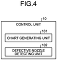
- FIG. 4 is a functional block diagram illustrating functions related to a defective nozzle detecting process. As illustrated in FIG. 4 , the control unit 10 functions as a chart generating unit 101 and a defective nozzle detecting unit 102.
- the chart generating unit 101 generates a defective nozzle detection chart C (see FIG. 5 ) in which lines extending in the sub-scanning direction are arranged stepwise, each line of which corresponds to a nozzle in the liquid discharging heads 220C, 220M, 220Y, 220K.
- FIG. 5 is a schematic illustrating one example of the defective nozzle detection chart C.
- the nozzle check lines L for detecting a defective nozzle and each corresponding to a nozzle of the liquid discharging heads 220C, 220M, 220Y, 220K are arranged stepwise.
- the number of rows of the nozzle check lines L, and the length of the nozzle check lines L are variable.
- the defective nozzle detection chart C also includes a start mark M1 for identifying the position where the defective nozzle detection is to be started, and an end mark M2 for identifying the position where the defective nozzle detection is to be ended.
- the longer sides of the lines, each of which corresponds to a nozzle are plotted in the sub-scanning (paper conveyance) direction, and the data is averaged in the sub-scanning direction, or the scanning sampling cycle is extended while using a scanning resolution in the sub-scanning direction lower than a scanning resolution in the main-scanning direction.
- the positions of the lines can be detected accurately, and, by determining a defective nozzle based on the difference in adjacent line pitches, it is possible to detect deflection at a nozzle even when there is an error in the scanning magnification.
- the length of the lines in the defective nozzle detection chart C is set to a length equal to or more than a length corresponding to two periods of longer one of periods corresponding to frequencies of relative vibrations of the liquid discharging heads 220C, 220M, 220Y, 220K, and of the two scanners 231, 232, with respect to the paper carrying drum 210 that functions as a conveying unit.
- the effect of the relative vibration between the paper sheet P and the scanners 231, 232 can be reduced, advantageously.
- the defective nozzle detecting unit 102 functions as a position detecting unit that performs an interpolating process to the pixel values of a plurality of pixels near the position of a line detected from the pixel values in the scanned data of the defective nozzle detection chart C, the scanned data being scanned by the two scanners 231, 232, and that detects a position where the differential of an interpolation function derived from the interpolating process is zero as the line position, and also determines a defective nozzle based on the difference in adjacent line pitches.
- FIG. 6 is a schematic for explaining the defective nozzle detecting process.
- the defective nozzle detecting unit 102 determines a defective nozzle detection range X by detecting the start mark M1 for starting the defective nozzle detection, and the end mark M2 for identifying the position where the defective nozzle detection is to be ended, in the main scanning position, from the image.
- the defective nozzle detecting unit 102 uses a mean value of Nm pixels (pixels in the length equal to or more than the length corresponding to the two or more periods of the longer one of the periods corresponding to the frequencies of the relative vibrations of the liquid discharging heads 220C, 220M, 220Y, 220K and of the scanners 231, 232, with respect to the paper carrying drum 210) in the sub-scanning direction. In this manner, the effect of the relative vibration between the paper sheet P and the scanners 231, 232 can be reduced, advantageously.
- the defective nozzle detecting unit 102 performs a process of detecting coordinates of the nozzle check lines L, from the starting position (the start mark M1) in the first row of the nozzle check lines L to the position of the end mark M2, or to the end of the image, along a detecting direction.
- the defective nozzle detecting unit 102 compares the pixel value of each pixel with a nozzle detection threshold T, and, if the pixel value is greater than the nozzle detection threshold T, determines that there is a nozzle check line L at the pixel.
- FIG. 7 is a schematic for explaining the interpolating process.
- the defective nozzle detecting unit 102 performs third-order spline interpolation to the pixel values of S pixels before and after the coordinate determined to be a nozzle check line L, being before and after in the main-scanning direction, and obtains a spline function. In this manner, detection can be performed accurately even with a low-resolution scanner.
- the defective nozzle detecting unit 102 obtains the X coordinate where the differential of the spline function is zero, and converts the value into units of millimeters based on the main scanning resolution of the X coordinate, and stores the resultant value as a nozzle position.
- the defective nozzle detecting unit 102 calculates differences regarding pitches between adjacent lines, and calculates a median regarding differences of pitches for one row of the nozzle check lines L.
- the defective nozzle detecting unit 102 uses the calculated median in determining lack (which means that a line is not formed because, for example, the liquid discharging head fails to discharge liquid from a corresponding nozzle) and deflection (which means that a position of a line is shifted because, for example, the liquid discharging head discharges liquid from a corresponding nozzle obliquely) at nozzles. In this manner, even when there is a variance in the scanning magnification, detection can be performed accurately, advantageously.
- the median does not need to be a median calculated for all the lines included in one row of the nozzle check lines L, and may be a median corresponding to several lines around a line of interest. In this manner, even when there is a deviation (aberration) in the scanning magnification, the detection can be performed accurately, advantageously.
- FIGS. 8A and 8B are schematics for explaining a process for determining lack and deflection.
- FIG. 8A illustrates a process for determining lack
- FIG. 8B illustrates a process for determining deflection.
- the defective nozzle detecting unit 102 determines that lack exists in some nozzles immediately before a nozzle check line L at which an absolute value of the pitch difference with respect to differences of pitches between adjacent lines and the median regarding the differences of the pitches for one row of the nozzle check lines L, is equal to or more than a half of the median. In other words, denoting pitches between adjacent lines as D n , D n+1 , D n+2 ..., the defective nozzle detecting unit 102 determines that lack exists in a nozzle when the following condition is satisfied. D n ⁇ D n + 1 ⁇ median / 2
- the defective nozzle detecting unit 102 obtains a mean value regarding differences of pitches of all the adjacent lines, excluding a nozzle determined that lack exists immediately before the nozzle.
- the defective nozzle detecting unit 102 then obtains the number of nozzles at which lack exists, by rounding, to the nearest integer, the value obtained by dividing the distance between the nozzle check lines L by the mean value, and stores the defective nozzle numbers.
- the defective nozzle detecting unit 102 determines that deflection occurs at the nozzle, and stores the nozzle number as a defective nozzle number. In other words, it is determined that deflection occurs at the nozzle when the following condition is satisfied. D n ⁇ Mean ⁇ Tm
- FIG. 9 is a flowchart illustrating the sequence of the overall defective nozzle detecting process. As illustrated in FIG. 9 , the defective nozzle detecting unit 102 repeats this defective nozzle detecting process for several rows of the nozzle check lines L, sequentially from the first row in the defective nozzle detection chart C, and detects the defective nozzles in every row. Details will be described later.
- the defective nozzle detecting unit 102 detects the position of the start mark M1 in the defective nozzle detection chart C to identify the position where the defective nozzle detection is to be started (Step S1).
- the defective nozzle detecting unit 102 then detects the position of the end mark M2 in the defective nozzle detection chart C to identify the position where the defective nozzle detection is to be ended (Step S2).
- the defective nozzle detecting unit 102 then detects a start nozzle position in each row of the nozzle check lines L within the range between the start mark M1 and the end mark M2 (Step S3).
- the defective nozzle detecting unit 102 then performs a process of detecting lack and deflection for several rows of the nozzle check lines L (Step S4).
- FIG. 10 is a flowchart illustrating the sequence of the lack and deflection detecting process corresponding to one row, performed at Step S4.
- the defective nozzle detecting unit 102 uses a mean value of Nm pixels in the sub-scanning direction, over the entire width of the row of the nozzle check lines L (Step S11).
- the defective nozzle detecting unit 102 then performs the process of detecting the coordinate of each of the nozzle check lines L along the detecting direction, from the starting position (start mark M1) to the position of the end mark M2 or the end of the image end, for every row of the nozzle check lines L (Step S12).
- FIG. 11 is a flowchart illustrating the sequence of a line coordinate detecting process at Step S12.
- the defective nozzle detecting unit 102 acquires a next pixel (Step S21), and determines whether the acquired pixel is at the position of the end mark M2 or the end of the image (Step S22).
- the defective nozzle detecting unit 102 ends the process.
- the defective nozzle detecting unit 102 determines that the pixel value of the acquired pixel is equal to or more than the nozzle detection threshold T (Step S23).
- the defective nozzle detecting unit 102 sets a line-detecting flag to OFF (Step S24), and ends the process.
- the defective nozzle detecting unit 102 determines that it is the position corresponding to a nozzle check line L, and determines whether the line-detecting flag is ON (Step S25).
- the defective nozzle detecting unit 102 ends the process.
- the defective nozzle detecting unit 102 sets the line-detecting flag to ON (Step S26), and performs third-order spline interpolation to the pixel value in the S pixels before and after the coordinate determined to be the nozzle check line L in the main-scanning direction, and obtains a spline function (Step S27).
- the defective nozzle detecting unit 102 then calculates an X coordinate where the differential of the spline function (Step S28) is zero (Step S29), and converts the X coordinate into a value in units of millimeter, based on the main scanning resolution in the X coordinate, stores the resultant value as a nozzle position (Step S30), and ends the process.
- the defective nozzle detecting unit 102 calculates the nozzle coordinates for each of the lines belonging to one row of the nozzle check lines L, from the start mark M1 to the position of the end mark M2 or the end of the image.
- the defective nozzle detecting unit 102 advances the process to Step S13, and performs a median/mean value calculating process.
- FIG. 12 is a flowchart illustrating the sequence of the median/mean value calculating process at Step S13.
- the defective nozzle detecting unit 102 calculates differences regarding pitches between adjacent lines (Step S41), calculates a mean value regarding the differences of the pitches for one row of the nozzle check lines L (Step S42), and calculates a median regarding the differences of the pitches for the one row of the nozzle check lines L (Step S43).
- the defective nozzle detecting unit 102 determines that lack exists in some nozzles immediately before the nozzle check line L, and stores the coordinate as the coordinate where lack exists (Step S45). The defective nozzle detecting unit 102 repeats the process at Step S44 and Step S45 by the number of times equal to the number of lines.
- the defective nozzle detecting unit 102 obtains a mean value regarding the differences of the pitches of all adjacent lines, excluding the nozzle stored as the coordinate where lack exists (Step S46), and obtains the median regarding differences of pitches between all adjacent lines (Step S47).
- the defective nozzle detecting unit 102 ends the median/mean value calculating process at Step S13, and ends the process.
- the defective nozzle detecting unit 102 then performs a lack and deflection detecting process (Step S15).
- FIG. 13 is a flowchart illustrating the sequence of the lack and deflection detecting process at Step S15.
- the defective nozzle detecting unit 102 obtains the number of nozzles at which lack exists, by rounding, to the nearest integer, the value obtained by dividing the distance between the nozzle check lines L by the mean value (Step S52). If there is no nozzle the coordinate of which is stored as the coordinate where lack exists (No at Step S51), the defective nozzle detecting unit 102 advances the process to Step S56.
- the defective nozzle detecting unit 102 then stores the defective nozzle number (Step S53), and increments the nozzle number (Step S54).
- the defective nozzle detecting unit 102 repeats Step S53 and Step S54 by the number of times equal to the number of nozzles at which lack exists.
- the defective nozzle detecting unit 102 then subtract (the number of nozzles at which lack exists ⁇ mean value) from the distance between the nozzle check lines L (Step S55).
- the defective nozzle detecting unit 102 determines that deflection occurs at the nozzle, stores the nozzle number as a defective nozzle number (Step S57), and increments the nozzle number (Step S58).
- the defective nozzle detecting unit 102 detects lack and deflection at nozzles.
- the defective nozzle detecting unit 102 performs the process of detecting lack and deflection at Step S4 for the number of rows, and ends the process.
- an interpolating process is performed to the pixel values in a plurality of pixels around the position of a line detected from the pixel values in the scanned data of the defective nozzle detection chart C scanned by the two scanners 231, 232 having a resolution lower than the printing resolution, and a defective nozzle is determined based on the difference in pitch from the adjacent line, by determining the position where the differential of the interpolation function derived from the interpolating process is zero, as the position of the line, instead of using the position of the line acquired by binarization.
- the defective nozzle detection chart C includes the lines each of which corresponds to a nozzle, and that are long in the sub-scanning (paper conveying) direction, a mean value of the data is calculated in the sub-scanning direction, or the scanning sampling cycle is extended in the sub-scanning direction.
- the positions of the lines can be detected accurately, and, by determining a defective nozzle based on the difference in pitch from the adjacent line, it is possible to detect deflection at a nozzle even when there is a scanning magnification error.
- the liquid discharging apparatus is applied as the inkjet recording apparatus 1, but the "liquid discharging apparatus” is not limited to an apparatus provided with a liquid discharging head that discharges liquid toward the surface to be dried in a recording medium to visualize some meaningful image such as characters and shapes with the discharged liquid, but also include an apparatus that forms a pattern or the like that itself has no meaning, for example.
- the material of the recording medium is not limited, and may be any material to which liquid can be attached, at least temporarily, such as paper, string, fiber, cloth, leather, metal, plastic, glass, wood, and ceramics, and may be a material used for a film product, a cloth product for clothing or the like, a building material such as wall paper or a floor material, or a leather product.
- liquid discharging apparatus may also include any means for feeding, conveying, and ejecting a material to which liquid can be attached, and any other pre-processing device and post-processing device, for example.
- liquid is not limited to a particular liquid, as long as the liquid has viscosity or surface tension allowing the liquid to be discharged from the head, but it is preferable to use liquid the viscosity of which is brought to a level equal to or lower than 30 mPa ⁇ s when being heated or cooled, at an ordinary temperature and under an ordinary pressure.
- the liquid is a solution, a suspension liquid, or an emulsion containing a solvent such as water or organic solvent, a colorant such as dye or pigment, a functionality imparting material such as a polymerizable compound, resin, and surfactant, a biocompatible material such as DNA, amino acid, protein, and calcium, an edible material such as a natural dye, and these types of liquid can be used as an ink for inkjet printing or as a surface treatment liquid, for example.
- a solvent such as water or organic solvent
- a colorant such as dye or pigment
- a functionality imparting material such as a polymerizable compound, resin, and surfactant
- a biocompatible material such as DNA, amino acid, protein, and calcium
- an edible material such as a natural dye
- liquid discharging apparatus includes an apparatus in which a liquid discharging head and a recording medium move relatively with respect to each other, but is not limited thereto. Specific examples include a serial type liquid discharging apparatus that moves the liquid discharging head, and a line type head liquid discharging apparatus that does not move the liquid discharging head.
- the “liquid discharging head” is a function component that discharges/sprays liquid from a discharge hole (nozzle).
- a discharge energy generating means such as a piezoelectric actuator (a layered piezoelectric element and a thin film piezoelectric element), a thermal actuator that uses a thermoelectric transducer such as a heat element, or an electrostatic actuator including a vibrating plate and facing electrodes, but the discharge energy generating means to be used is not limited to any particular means.
- liquid discharging apparatus is applied as the inkjet recording apparatus 1, but without limitation thereto, the liquid discharging apparatus may be applied to a printer for a continuous slip.
- FIG. 14 is a schematic illustrating an overall structure of another inkjet recording apparatus 1a.
- the inkjet recording apparatus 1a includes a sheet feeding unit 100a having a roll of recording medium Pa that is a long paper sheet, an image forming unit 200a, a drying unit 300a for drying the recording medium Pa, and a paper ejecting unit 400a around which the recording medium Pa having an image formed is wound.
- a scanner 500 for scanning the recording medium Pa after the image forming process is disposed.
- the recording medium Pa is continuous paper wound in a roll (roll paper), and the recording medium Pa is taken out from the sheet feeding unit 100a by the conveyance roller, and conveyed above a platen 600 of the image forming unit 200a, and wound by the paper ejecting unit 400a.
- the inkjet recording apparatus 1a may include a pre-processing unit that applies a pre-treatment liquid to the recording medium Pa, and a pre-process drying unit for drying the recording medium Pa applied with the pre-treatment liquid.
- the tension across the paper may vary in the direction perpendicularly intersecting with the conveyance direction (the main-scanning direction), and the paper may become offset toward one side due to degree of parallelization of the conveyance rollers, for example. This may cause the recording medium to meander.
- Control for correcting such paper meandering of paper is achieved by disposing a sensor for detecting a paper edge along a conveying path, detecting the amount by which the paper becomes offset toward one side, and tilting the conveyance roller in accordance with the detected amount. This correction may cause the paper to meander.
- This meandering is detected as a low-frequency vibration (of several hertz).
- any of the above-described apparatus, devices or units can be implemented as a hardware apparatus, such as a special-purpose circuit or device, or as a hardware/software combination, such as a processor executing a software program.
- any one of the above-described and other methods of the present invention may be embodied in the form of a computer program stored in any kind of storage medium.
- storage mediums include, but are not limited to, flexible disk, hard disk, optical discs, magneto-optical discs, magnetic tapes, nonvolatile memory, semiconductor memory, read-only-memory (ROM), etc.
- any one of the above-described and other methods of the present invention may be implemented by an application specific integrated circuit (ASIC), a digital signal processor (DSP) or a field programmable gate array (FPGA), prepared by interconnecting an appropriate network of conventional component circuits or by a combination thereof with one or more conventional general purpose microprocessors or signal processors programmed accordingly.
- ASIC application specific integrated circuit
- DSP digital signal processor
- FPGA field programmable gate array
- Processing circuitry includes a programmed processor, as a processor includes circuitry.
- a processing circuit also includes devices such as an application specific integrated circuit (ASIC), digital signal processor (DSP), field programmable gate array (FPGA) and conventional circuit components arranged to perform the recited functions.
- ASIC application specific integrated circuit
- DSP digital signal processor
- FPGA field programmable gate array
Landscapes
- Engineering & Computer Science (AREA)
- Quality & Reliability (AREA)
- Ink Jet (AREA)
Abstract
Description
- The present invention relates to a liquid discharging apparatus.
- In a line head liquid discharging apparatus, in order to prevent deterioration of image quality due to non-discharge or discharge deflection, a technique for detecting a defective nozzle has conventionally been known.
- Japanese Patent No.
4684801 4684801 - However, with the technique disclosed in Japanese Patent No.
4684801 - Furthermore, because the defective nozzle is determined by comparison with the ideal data, it has been impossible to detect the defective nozzle accurately when there is a disturbance such as magnification in the scanned data, a skew, and vibration.
- The present invention is made in consideration of the above, and it is an object of the present invention to detect a defective nozzle highly accurately, with a shorter processing time and a smaller memory area.
- A liquid discharging apparatus includes a conveying unit, a liquid discharging head, a scanner, a chart generating unit, and a position detecting unit. The conveying unit is configured to convey a recording medium. The liquid discharging head includes nozzles arranged linearly and is configured to discharge liquid onto the recording medium conveyed by the conveying unit. The scanner is installed in such a manner that a main-scanning direction of the scanner is aligned with a direction in which the nozzles of the liquid discharging head are arranged. The chart generating unit is configured to generate a defective nozzle detection chart in which lines in a sub-scanning direction corresponding to the respective nozzles of the liquid discharging head are arranged. The position detecting unit is configured to perform an interpolating process on pixel values of a plurality of pixels around a line position detected from pixel values of scanned data of the defective nozzle detection chart scanned by the scanner, and detect a position where a differential of an interpolation function derived from the interpolating process is zero, as a line position.
- According to an aspect of the present invention, by limiting the range of data to which the interpolating process is applied, defective nozzles can be detected accurately, with a shorter processing time and a smaller memory area, advantageously.
-
-
FIG. 1 is a schematic illustrating an overall structure of an inkjet recording apparatus according to an embodiment; -
FIG. 2 is a schematic illustrating an example of how two scanners are arranged; -
FIG. 3 is a block diagram illustrating a configuration for controlling the inkjet recording apparatus; -
FIG. 4 is a functional block diagram illustrating functions related to a defective nozzle detecting process; -
FIG. 5 is a schematic illustrating one example of a defective nozzle detection chart; -
FIG. 6 is a schematic for explaining the defective nozzle detecting process; -
FIG. 7 is a schematic for explaining an interpolating process; -
FIGS. 8A and 8B are schematics for explaining a process for determining lack and deflection; -
FIG. 9 is a flowchart illustrating the sequence of the overall defective nozzle detecting process; -
FIG. 10 is a flowchart illustrating the sequence of a lack and deflection detecting process for one row at Step S4; -
FIG. 11 is a flowchart illustrating the sequence of a line coordinate detecting process at Step S12; -
FIG. 12 is a flowchart illustrating the sequence of a median/mean value calculating process at Step S13; -
FIG. 13 is a flowchart illustrating the sequence of the lack and deflection detecting process at Step S15; and -
FIG. 14 is a schematic illustrating an overall structure of another inkjet recording apparatus according to the embodiment. - The accompanying drawings are intended to depict exemplary embodiments of the present invention and should not be interpreted to limit the scope thereof. Identical or similar reference numerals designate identical or similar components throughout the various drawings.
- The terminology used herein is for the purpose of describing particular embodiments only and is not intended to be limiting of the present invention.
- As used herein, the singular forms "a", "an" and "the" are intended to include the plural forms as well, unless the context clearly indicates otherwise.
- In describing preferred embodiments illustrated in the drawings, specific terminology may be employed for the sake of clarity. However, the disclosure of this patent specification is not intended to be limited to the specific terminology so selected, and it is to be understood that each specific element includes all technical equivalents that have the same function, operate in a similar manner, and achieve a similar result.
- An embodiment of the present invention will be described in detail below with reference to the drawings.
- A liquid discharging apparatus according to an embodiment will now be explained in detail with reference to the appended drawings. Explained in the embodiment is an application of a liquid discharging apparatus to an inkjet-based inkjet recording apparatus.
-
FIG. 1 is a schematic illustrating an overall structure of aninkjet recording apparatus 1 according to the embodiment. As illustrated inFIG. 1 , theinkjet recording apparatus 1 mainly includes asheet feeding unit 100, animage forming unit 200, adrying unit 300, and apaper ejecting unit 400. Theinkjet recording apparatus 1 causes theimage forming unit 200 to form an image on paper sheet P that is a recording medium serving as a sheet member fed from thesheet feeding unit 100, using ink that is a liquid for forming images. Theinkjet recording apparatus 1 then causes thedrying unit 300 to dry the ink attached on the paper sheet P, and causes thepaper ejecting unit 400 to eject the paper sheet P. - To begin with, the
sheet feeding unit 100 will be explained. - The
sheet feeding unit 100 mainly includes asheet feeding tray 110 on which a plurality of paper sheets P are stacked, afeeder device 120 that separates one paper sheet P at a time, and sends the sheet out of thesheet feeding tray 110, and aregistration roller pair 130 that sends the paper sheet P into theimage forming unit 200. - As the
feeder device 120, any feeder device may be used, including a device using rollers or rolling bodies, or a device using air suctioning. - After the leading edge of the paper sheet P sent out of the
sheet feeding tray 110 by thefeeder device 120 reaches theregistration roller pair 130, thesheet feeding unit 100 drives theregistration roller pair 130 at a predetermined timing. In this manner, the paper sheet P is fed into theimage forming unit 200. - In this embodiment, the configuration of the
sheet feeding unit 100 is not limited, as long as the structure sends the paper sheet P into theimage forming unit 200. - The
image forming unit 200 will now be explained. - The
image forming unit 200 mainly includes areceiving roll 201, apaper carrying drum 210, anink discharging unit 220, and apassing roll 202. Thereceiving roll 201 receives the fed paper sheet P. Thepaper carrying drum 210 functioning as a conveying unit conveys the paper sheet P fed by thereceiving roll 201, by carrying the paper sheet P on the outer circumferential surface of thepaper carrying drum 210. Theink discharging unit 220 discharges the ink onto the paper sheet P that is being carried by thepaper carrying drum 210. Thepassing roll 202 passes the paper sheet P that is being conveyed by thepaper carrying drum 210 into thedrying unit 300. - A paper gripper provided on the surface of the receiving
roll 201 grips the leading edge of the paper sheet P being conveyed from thesheet feeding unit 100 into theimage forming unit 200, and the paper sheet P is conveyed as the surface of thereceiving roll 201 moves. The paper sheet P being conveyed by thereceiving roll 201 is passed onto thepaper carrying drum 210 at the position where thereceiving roll 201 faces thepaper carrying drum 210. - A paper gripper is also provided on the surface of the
paper carrying drum 210, and the leading edge of the paper sheet P is gripped by the paper gripper. A plurality of suction holes are also provided on the surface of thepaper carrying drum 210 in a distributed manner, and asuction device 211 generates a suctioning airflow suctioning into thepaper carrying drum 210 in each of the suction holes. - The paper sheet P passed from the receiving
roll 201 onto thepaper carrying drum 210 is conveyed as the surface of thepaper carrying drum 210 moves, with the leading edge thereof gripped by the paper gripper, and while being attracted to the surface of thepaper carrying drum 210 by the suctioning airflow. - The
ink discharging unit 220 according to the embodiment is a line head that forms an image by discharging inks in four colors of cyan (C), magenta (M), yellow (Y), and black (K), and includes individualliquid discharging heads - As the
liquid discharging heads - The discharging operations of the
liquid discharging heads ink discharging unit 220 are controlled by driving signals corresponding to image information. When the paper sheet P carried on thepaper carrying drum 210 is passed through the section where thepaper carrying drum 210 faces theink discharging unit 220, the inks in the respective colors are discharged from theliquid discharging heads - In this embodiment, the configuration of the
image forming unit 200 is not limited, as long as the image forming unit forms an image by attaching some liquid onto the paper sheet P. - In addition, as illustrated in
FIG. 1 , theimage forming unit 200 includes twoscanners ink discharging unit 220 in the direction in which the paper sheet P is conveyed. These twoscanners FIG. 5 ). The resolution of the twoscanners image forming unit 200. - The
image forming unit 200 causes theink discharging unit 220 to print the defective nozzle detection chart C while the paper sheet P is being conveyed with the leading edge thereof being gripped by the paper gripper provided on the surface of thepaper carrying drum 210, and while being attracted by being suctioned, and, immediately after the defective nozzle detection chart C is printed, the twoscanners -
FIG. 2 is a schematic illustrating an example of how these twoscanners FIG. 2 , two of the scanner (front) 231 and the scanner (rear) 232 are positioned in a staggered arrangement so that the entire page of the paper sheet P is scanned thereby. More specifically, the twoscanners scanners - In this embodiment, the two
scanners - The drying
unit 300 will now be explained. - The drying
unit 300 mainly includes adrying mechanism 301 for drying the ink attached to the paper sheet P by theimage forming unit 200, and a conveying mechanism 302 for conveying the paper sheet P being conveyed from theimage forming unit 200. - The drying
unit 300 causes the conveying mechanism 302 to receive the paper sheet P conveyed by theimage forming unit 200, then to convey the paper sheet P through thedrying mechanism 301, and to pass the paper sheet P to thepaper ejecting unit 400. The dryingunit 300 then applies a drying process to the ink on the paper sheet P as the paper sheet P is passed through thedrying mechanism 301. As a result, the liquid component such as water in the ink evaporates, so that the ink adheres to the paper sheet P, and the curl of the paper sheet P is suppressed. - The
paper ejecting unit 400 will now be explained. - The
paper ejecting unit 400 mainly includes apaper ejection tray 410 on which a plurality of paper sheets P are stacked. Thepaper ejecting unit 400 stores the paper sheet P received from the dryingunit 300, by sequentially stacking one sheet after another on thepaper ejection tray 410. - In this embodiment, the configuration of the
paper ejecting unit 400 is not limited, as long as the paper sheet P is ejected thereby. - Other functional units will now be explained.
- The
inkjet recording apparatus 1 according to the embodiment includes thesheet feeding unit 100, theimage forming unit 200, the dryingunit 300, and thepaper ejecting unit 400, but any other functional units may be added as appropriate. For example, a pre-processing unit performing a pre-process before executing an image formation may be added between thesheet feeding unit 100 and theimage forming unit 200, or a post-processing unit performing a post-process after the image formation may be added between the dryingunit 300 and thepaper ejecting unit 400. - Examples of the pre-processing unit include a pre-processing unit for performing a treatment liquid applying process in which a treatment liquid reacting with the ink and suppressing bleeding of the ink is applied to the paper sheet P, but the pre-process is not limited to a particular process. Furthermore, examples of the post-processing unit include a post-processing unit performing a paper reversing and conveying process for reversing the paper sheet P having an image formed by the
image forming unit 200, and conveying the reversed paper sheet P to theimage forming unit 200 again so that images are formed on both sides of the paper sheet P, a post-processing unit performing a process for binding a plurality of paper sheets P having images formed thereon, a straightening mechanism for straitening a deformed paper sheet P, and a cooling mechanism for cooling the paper sheet P, but the post-process is not limited to a particular process. - A configuration for controlling the
inkjet recording apparatus 1 will now be explained. -
FIG. 3 is a block diagram illustrating a configuration for controlling theinkjet recording apparatus 1. As illustrated inFIG. 3 , theinkjet recording apparatus 1 includes acontrol unit 10 that governs the control of the entire apparatus. Thecontrol unit 10 includes a central processing unit (CPU) 11 that performs the control, a read-only memory (ROM) 12, a random access memory (RAM) 13, a memory 14, and an application-specific integrated circuit (ASIC) 15. TheROM 12 stores therein a computer programs executed by theCPU 11 and other fixed data. TheRAM 13 temporarily stores therein image data, for example. The memory 14 is a rewritable non-volatile memory for storing data even after the power of theinkjet recording apparatus 1 is shut down. TheASIC 15 performs image processing such as various types of signal processing to the image data and rearrangement of the image data, and other input/output signal processing for controlling the entire apparatus. - As illustrated in
FIG. 3 , thecontrol unit 10 also includes a host interface (I/F) 16, a head driving control unit 17, amotor control unit 18, an I/O 19, and ascanner control unit 8. - The host I/F 16 transmits and receives image data (print data) and control signals to and from a host, over a cable or a network. Examples of the host connected to the
inkjet recording apparatus 1 include an information processing system such as a personal computer, an image scanning device such as image scanner, and an image capturing device such as a digital camera. - The I/
O 19 connects various types ofsensors 25 such as a humidity sensor, a temperature sensor, and other sensors. The I/O 19 receives inputs of detection signals from thevarious sensors 25. - The head driving control unit 17 is for controlling driving of the
ink discharging unit 220, and includes means for transferring data. More specifically, the head driving control unit 17 transfers image data as serial data. The head driving control unit 17 also generates a transfer clock and a latch signal that are required in transferring image data and confirming the transfer, and a driving waveform used when the ink droplets are to be discharged from theink discharging unit 220. The head driving control unit 17 then inputs the generated driving waveform and the like to a driving circuit provided internal of theink discharging unit 220. - The
motor control unit 18 is for driving a motor M that causes the receivingroll 201, thepaper carrying drum 210, the passingroll 202, and the like to rotate. - The
scanner control unit 8 controls the twoscanners - The
control unit 10 also connects an operation panel 60 for inputting and displaying information required in theinkjet recording apparatus 1. - The
control unit 10 controls these units comprehensively by causing theCPU 11 to deploy a computer program read from the ROM 12 (or the memory 14) onto theRAM 13, and to execute the computer program. More specifically, based on a printing mode set via the operation panel 60, theCPU 11 reads control content set according to the printing mode, the control setting being set for each of such printing modes, from the ROM 12 (or the memory 14). TheCPU 11 then executes control explained below, by controlling the functional units based on the control settings read from the ROM 12 (or the memory 14). - A computer program executed on the
inkjet recording apparatus 1 according to the embodiment may be provided in a manner recorded in a computer-readable recording medium such as a compact-disc read-only memory (CD-ROM), a flexible disk (FD), a compact-disc recordable (CD-R), and a digital versatile disc (DVD), as a file in an installable or executable format. - Furthermore, the computer program executed on the
inkjet recording apparatus 1 according to the embodiment may be stored in a computer connected to a network such as the Internet, and made available for download over the network. Furthermore, the computer program executed on theinkjet recording apparatus 1 according to the embodiment may be provided or distributed over a network such as the Internet. - Furthermore, the computer program executed on the
inkjet recording apparatus 1 according to the embodiment may be provided in a manner incorporated in a ROM or the like, in advance. - Functions related to a defective nozzle detecting process performed by the
control unit 10 in theinkjet recording apparatus 1 will now be explained. -
FIG. 4 is a functional block diagram illustrating functions related to a defective nozzle detecting process. As illustrated inFIG. 4 , thecontrol unit 10 functions as achart generating unit 101 and a defective nozzle detecting unit 102. - The
chart generating unit 101 generates a defective nozzle detection chart C (seeFIG. 5 ) in which lines extending in the sub-scanning direction are arranged stepwise, each line of which corresponds to a nozzle in theliquid discharging heads -
FIG. 5 is a schematic illustrating one example of the defective nozzle detection chart C. As illustrated inFIG. 5 , in the defective nozzle detection chart C, the nozzle check lines L for detecting a defective nozzle and each corresponding to a nozzle of theliquid discharging heads - As illustrated in
FIG. 5 , the defective nozzle detection chart C also includes a start mark M1 for identifying the position where the defective nozzle detection is to be started, and an end mark M2 for identifying the position where the defective nozzle detection is to be ended. - As illustrated in
FIG. 5 , in the defective nozzle detection chart C, the longer sides of the lines, each of which corresponds to a nozzle, are plotted in the sub-scanning (paper conveyance) direction, and the data is averaged in the sub-scanning direction, or the scanning sampling cycle is extended while using a scanning resolution in the sub-scanning direction lower than a scanning resolution in the main-scanning direction. In this manner, even when there is some vibration or skew, the positions of the lines can be detected accurately, and, by determining a defective nozzle based on the difference in adjacent line pitches, it is possible to detect deflection at a nozzle even when there is an error in the scanning magnification. - More specifically, the length of the lines in the defective nozzle detection chart C is set to a length equal to or more than a length corresponding to two periods of longer one of periods corresponding to frequencies of relative vibrations of the
liquid discharging heads scanners paper carrying drum 210 that functions as a conveying unit. In this manner, the effect of the relative vibration between the paper sheet P and thescanners - Referring back to
FIG. 4 , the defective nozzle detecting unit 102 functions as a position detecting unit that performs an interpolating process to the pixel values of a plurality of pixels near the position of a line detected from the pixel values in the scanned data of the defective nozzle detection chart C, the scanned data being scanned by the twoscanners -
FIG. 6 is a schematic for explaining the defective nozzle detecting process. As illustrated inFIG. 6 , to begin with, the defective nozzle detecting unit 102 determines a defective nozzle detection range X by detecting the start mark M1 for starting the defective nozzle detection, and the end mark M2 for identifying the position where the defective nozzle detection is to be ended, in the main scanning position, from the image. In the process of detecting the nozzle check lines L, the defective nozzle detecting unit 102 uses a mean value of Nm pixels (pixels in the length equal to or more than the length corresponding to the two or more periods of the longer one of the periods corresponding to the frequencies of the relative vibrations of theliquid discharging heads scanners scanners - As illustrated in
FIG. 6 , the defective nozzle detecting unit 102 performs a process of detecting coordinates of the nozzle check lines L, from the starting position (the start mark M1) in the first row of the nozzle check lines L to the position of the end mark M2, or to the end of the image, along a detecting direction. - The defective nozzle detecting unit 102 compares the pixel value of each pixel with a nozzle detection threshold T, and, if the pixel value is greater than the nozzle detection threshold T, determines that there is a nozzle check line L at the pixel.
- The defective nozzle detecting unit 102 then performs an interpolating process.
FIG. 7 is a schematic for explaining the interpolating process. - As illustrated in
FIG. 7 , the defective nozzle detecting unit 102 performs third-order spline interpolation to the pixel values of S pixels before and after the coordinate determined to be a nozzle check line L, being before and after in the main-scanning direction, and obtains a spline function. In this manner, detection can be performed accurately even with a low-resolution scanner. - The defective nozzle detecting unit 102 obtains the X coordinate where the differential of the spline function is zero, and converts the value into units of millimeters based on the main scanning resolution of the X coordinate, and stores the resultant value as a nozzle position.
- After calculating the coordinate of each of the nozzle check lines L included in one row, the defective nozzle detecting unit 102 calculates differences regarding pitches between adjacent lines, and calculates a median regarding differences of pitches for one row of the nozzle check lines L. The defective nozzle detecting unit 102 uses the calculated median in determining lack (which means that a line is not formed because, for example, the liquid discharging head fails to discharge liquid from a corresponding nozzle) and deflection (which means that a position of a line is shifted because, for example, the liquid discharging head discharges liquid from a corresponding nozzle obliquely) at nozzles. In this manner, even when there is a variance in the scanning magnification, detection can be performed accurately, advantageously.
- The median does not need to be a median calculated for all the lines included in one row of the nozzle check lines L, and may be a median corresponding to several lines around a line of interest. In this manner, even when there is a deviation (aberration) in the scanning magnification, the detection can be performed accurately, advantageously.
- The defective nozzle detecting unit 102 then determines lack and deflection.
FIGS. 8A and 8B are schematics for explaining a process for determining lack and deflection.FIG. 8A illustrates a process for determining lack, andFIG. 8B illustrates a process for determining deflection. - As illustrated in
FIG. 8A , the defective nozzle detecting unit 102 determines that lack exists in some nozzles immediately before a nozzle check line L at which an absolute value of the pitch difference with respect to differences of pitches between adjacent lines and the median regarding the differences of the pitches for one row of the nozzle check lines L, is equal to or more than a half of the median. In other words, denoting pitches between adjacent lines as Dn, Dn+1, Dn+2 ..., the defective nozzle detecting unit 102 determines that lack exists in a nozzle when the following condition is satisfied.
- In addition, as illustrated in
FIG. 8B , the defective nozzle detecting unit 102 obtains a mean value regarding differences of pitches of all the adjacent lines, excluding a nozzle determined that lack exists immediately before the nozzle. - The defective nozzle detecting unit 102 then obtains the number of nozzles at which lack exists, by rounding, to the nearest integer, the value obtained by dividing the distance between the nozzle check lines L by the mean value, and stores the defective nozzle numbers.
- If the absolute value of a difference between a difference between adjacent nozzles and the mean value is equal to or more than a threshold Tm for determining deflection, the defective nozzle detecting unit 102 determines that deflection occurs at the nozzle, and stores the nozzle number as a defective nozzle number. In other words, it is determined that deflection occurs at the nozzle when the following condition is satisfied.

- The sequence of the defective nozzle detecting process will now be explained.
-
FIG. 9 is a flowchart illustrating the sequence of the overall defective nozzle detecting process. As illustrated inFIG. 9 , the defective nozzle detecting unit 102 repeats this defective nozzle detecting process for several rows of the nozzle check lines L, sequentially from the first row in the defective nozzle detection chart C, and detects the defective nozzles in every row. Details will be described later. - To begin with, the defective nozzle detecting unit 102 detects the position of the start mark M1 in the defective nozzle detection chart C to identify the position where the defective nozzle detection is to be started (Step S1).
- The defective nozzle detecting unit 102 then detects the position of the end mark M2 in the defective nozzle detection chart C to identify the position where the defective nozzle detection is to be ended (Step S2).
- The defective nozzle detecting unit 102 then detects a start nozzle position in each row of the nozzle check lines L within the range between the start mark M1 and the end mark M2 (Step S3).
- The defective nozzle detecting unit 102 then performs a process of detecting lack and deflection for several rows of the nozzle check lines L (Step S4).
-
FIG. 10 is a flowchart illustrating the sequence of the lack and deflection detecting process corresponding to one row, performed at Step S4. As illustrated inFIG. 10 , the defective nozzle detecting unit 102 uses a mean value of Nm pixels in the sub-scanning direction, over the entire width of the row of the nozzle check lines L (Step S11). - The defective nozzle detecting unit 102 then performs the process of detecting the coordinate of each of the nozzle check lines L along the detecting direction, from the starting position (start mark M1) to the position of the end mark M2 or the end of the image end, for every row of the nozzle check lines L (Step S12).
-
FIG. 11 is a flowchart illustrating the sequence of a line coordinate detecting process at Step S12. As illustrated inFIG. 11 , to begin with, the defective nozzle detecting unit 102 acquires a next pixel (Step S21), and determines whether the acquired pixel is at the position of the end mark M2 or the end of the image (Step S22). - If the acquired pixel is determined to be at the position of the end mark M2 or the end of the image (Yes at Step S22), the defective nozzle detecting unit 102 ends the process.
- If the acquired pixel is not at the position of the end mark M2 or the end of the image (No at Step S22), the defective nozzle detecting unit 102 determines that the pixel value of the acquired pixel is equal to or more than the nozzle detection threshold T (Step S23).
- If the acquired pixel value is determined not to be equal to or more than the nozzle detection threshold T (No at Step S23), the defective nozzle detecting unit 102 sets a line-detecting flag to OFF (Step S24), and ends the process.
- If it is determined that the acquired pixel value is equal to or more than the nozzle detection threshold T (Yes at Step S23), the defective nozzle detecting unit 102 determines that it is the position corresponding to a nozzle check line L, and determines whether the line-detecting flag is ON (Step S25).
- If it is determined that the line-detecting flag is ON (Yes at Step S25), the defective nozzle detecting unit 102 ends the process.
- If it is determined that the line-detecting flag is not ON (No at Step S25), the defective nozzle detecting unit 102 sets the line-detecting flag to ON (Step S26), and performs third-order spline interpolation to the pixel value in the S pixels before and after the coordinate determined to be the nozzle check line L in the main-scanning direction, and obtains a spline function (Step S27).
- The defective nozzle detecting unit 102 then calculates an X coordinate where the differential of the spline function (Step S28) is zero (Step S29), and converts the X coordinate into a value in units of millimeter, based on the main scanning resolution in the X coordinate, stores the resultant value as a nozzle position (Step S30), and ends the process.
- By repeating the process at Step S12 described above, the defective nozzle detecting unit 102 calculates the nozzle coordinates for each of the lines belonging to one row of the nozzle check lines L, from the start mark M1 to the position of the end mark M2 or the end of the image.
- Referring back to
FIG. 10 , when the line coordinate detecting process is ended, the defective nozzle detecting unit 102 advances the process to Step S13, and performs a median/mean value calculating process. -
FIG. 12 is a flowchart illustrating the sequence of the median/mean value calculating process at Step S13. As illustrated inFIG. 12 , to begin with, the defective nozzle detecting unit 102 calculates differences regarding pitches between adjacent lines (Step S41), calculates a mean value regarding the differences of the pitches for one row of the nozzle check lines L (Step S42), and calculates a median regarding the differences of the pitches for the one row of the nozzle check lines L (Step S43). - If the absolute value of the pitch difference with respect to differences of pitches between adjacent lines and the median regarding the differences of the pitches for one row of the nozzle check lines L, is equal to or more than a half of the median (Yes at Step S44), the defective nozzle detecting unit 102 determines that lack exists in some nozzles immediately before the nozzle check line L, and stores the coordinate as the coordinate where lack exists (Step S45). The defective nozzle detecting unit 102 repeats the process at Step S44 and Step S45 by the number of times equal to the number of lines.
- The defective nozzle detecting unit 102 obtains a mean value regarding the differences of the pitches of all adjacent lines, excluding the nozzle stored as the coordinate where lack exists (Step S46), and obtains the median regarding differences of pitches between all adjacent lines (Step S47).
- The defective nozzle detecting unit 102 ends the median/mean value calculating process at Step S13, and ends the process.
- Referring back to
FIG. 10 , when the median/mean value calculating process is ended, the defective nozzle detecting unit 102 advances the process to Step S14, and sets:
starting nozzle number in each row = nozzle number at start mark + number of rows - 1. - The defective nozzle detecting unit 102 then performs a lack and deflection detecting process (Step S15).
-
FIG. 13 is a flowchart illustrating the sequence of the lack and deflection detecting process at Step S15. As illustrated inFIG. 13 , to begin with, if there is any nozzle the coordinate of which is stored as the coordinate where lack exists (Yes at Step S51), the defective nozzle detecting unit 102 obtains the number of nozzles at which lack exists, by rounding, to the nearest integer, the value obtained by dividing the distance between the nozzle check lines L by the mean value (Step S52). If there is no nozzle the coordinate of which is stored as the coordinate where lack exists (No at Step S51), the defective nozzle detecting unit 102 advances the process to Step S56. - The defective nozzle detecting unit 102 then stores the defective nozzle number (Step S53), and increments the nozzle number (Step S54). The defective nozzle detecting unit 102 repeats Step S53 and Step S54 by the number of times equal to the number of nozzles at which lack exists.
- The defective nozzle detecting unit 102 then subtract (the number of nozzles at which lack exists × mean value) from the distance between the nozzle check lines L (Step S55).
- If the absolute value of the difference between the adjacent nozzle difference and the mean value is equal to or more than the threshold Tm (Yes at Step S56), the defective nozzle detecting unit 102 determines that deflection occurs at the nozzle, stores the nozzle number as a defective nozzle number (Step S57), and increments the nozzle number (Step S58).
- By repeating the process at Step S15 by the number of times equal to the number of lines, the defective nozzle detecting unit 102 detects lack and deflection at nozzles.
- Through the process described above, the process for detecting lack and deflection for all the rows of the nozzle check line L, performed at Step S4 illustrated in
FIG. 9 , is ended. - The defective nozzle detecting unit 102 performs the process of detecting lack and deflection at Step S4 for the number of rows, and ends the process.
- In the manner described above, according to the embodiment, an interpolating process is performed to the pixel values in a plurality of pixels around the position of a line detected from the pixel values in the scanned data of the defective nozzle detection chart C scanned by the two
scanners scanners - Furthermore, the defective nozzle detection chart C includes the lines each of which corresponds to a nozzle, and that are long in the sub-scanning (paper conveying) direction, a mean value of the data is calculated in the sub-scanning direction, or the scanning sampling cycle is extended in the sub-scanning direction. In this manner, even when there is some vibration or skew, the positions of the lines can be detected accurately, and, by determining a defective nozzle based on the difference in pitch from the adjacent line, it is possible to detect deflection at a nozzle even when there is a scanning magnification error.
- Explained in the embodiment is an example in which the liquid discharging apparatus is applied as the
inkjet recording apparatus 1, but the "liquid discharging apparatus" is not limited to an apparatus provided with a liquid discharging head that discharges liquid toward the surface to be dried in a recording medium to visualize some meaningful image such as characters and shapes with the discharged liquid, but also include an apparatus that forms a pattern or the like that itself has no meaning, for example. - Furthermore, the material of the recording medium is not limited, and may be any material to which liquid can be attached, at least temporarily, such as paper, string, fiber, cloth, leather, metal, plastic, glass, wood, and ceramics, and may be a material used for a film product, a cloth product for clothing or the like, a building material such as wall paper or a floor material, or a leather product.
- Furthermore, the "liquid discharging apparatus" may also include any means for feeding, conveying, and ejecting a material to which liquid can be attached, and any other pre-processing device and post-processing device, for example.
- The "liquid" is not limited to a particular liquid, as long as the liquid has viscosity or surface tension allowing the liquid to be discharged from the head, but it is preferable to use liquid the viscosity of which is brought to a level equal to or lower than 30 mPa●s when being heated or cooled, at an ordinary temperature and under an ordinary pressure. More specifically, the liquid is a solution, a suspension liquid, or an emulsion containing a solvent such as water or organic solvent, a colorant such as dye or pigment, a functionality imparting material such as a polymerizable compound, resin, and surfactant, a biocompatible material such as DNA, amino acid, protein, and calcium, an edible material such as a natural dye, and these types of liquid can be used as an ink for inkjet printing or as a surface treatment liquid, for example.
- Furthermore, the "liquid discharging apparatus" includes an apparatus in which a liquid discharging head and a recording medium move relatively with respect to each other, but is not limited thereto. Specific examples include a serial type liquid discharging apparatus that moves the liquid discharging head, and a line type head liquid discharging apparatus that does not move the liquid discharging head.
- Furthermore, the "liquid discharging head" is a function component that discharges/sprays liquid from a discharge hole (nozzle). As an energy generation source for discharging the liquid, it is possible to use a discharge energy generating means such as a piezoelectric actuator (a layered piezoelectric element and a thin film piezoelectric element), a thermal actuator that uses a thermoelectric transducer such as a heat element, or an electrostatic actuator including a vibrating plate and facing electrodes, but the discharge energy generating means to be used is not limited to any particular means.
- Explained in this embodiment is an example in which the liquid discharging apparatus is applied as the
inkjet recording apparatus 1, but without limitation thereto, the liquid discharging apparatus may be applied to a printer for a continuous slip. -
FIG. 14 is a schematic illustrating an overall structure of anotherinkjet recording apparatus 1a. As illustrated inFIG. 14 , theinkjet recording apparatus 1a includes asheet feeding unit 100a having a roll of recording medium Pa that is a long paper sheet, animage forming unit 200a, adrying unit 300a for drying the recording medium Pa, and apaper ejecting unit 400a around which the recording medium Pa having an image formed is wound. Subsequently to theimage forming unit 200a, ascanner 500 for scanning the recording medium Pa after the image forming process is disposed. - The recording medium Pa is continuous paper wound in a roll (roll paper), and the recording medium Pa is taken out from the
sheet feeding unit 100a by the conveyance roller, and conveyed above aplaten 600 of theimage forming unit 200a, and wound by thepaper ejecting unit 400a. - It is also possible for the
inkjet recording apparatus 1a to include a pre-processing unit that applies a pre-treatment liquid to the recording medium Pa, and a pre-process drying unit for drying the recording medium Pa applied with the pre-treatment liquid. - When such long recording medium Pa is to be conveyed, the tension across the paper may vary in the direction perpendicularly intersecting with the conveyance direction (the main-scanning direction), and the paper may become offset toward one side due to degree of parallelization of the conveyance rollers, for example. This may cause the recording medium to meander. Control for correcting such paper meandering of paper is achieved by disposing a sensor for detecting a paper edge along a conveying path, detecting the amount by which the paper becomes offset toward one side, and tilting the conveyance roller in accordance with the detected amount. This correction may cause the paper to meander. This meandering is detected as a low-frequency vibration (of several hertz).
- The above-described embodiments are illustrative and do not limit the present invention. Thus, numerous additional modifications and variations are possible in light of the above teachings. For example, at least one element of different illustrative and exemplary embodiments herein may be combined with each other or substituted for each other within the scope of this disclosure and appended claims. Further, features of components of the embodiments, such as the number, the position, and the shape are not limited the embodiments and thus may be preferably set. It is therefore to be understood that within the scope of the appended claims, the disclosure of the present invention may be practiced otherwise than as specifically described herein.
- The method steps, processes, or operations described herein are not to be construed as necessarily requiring their performance in the particular order discussed or illustrated, unless specifically identified as an order of performance or clearly identified through the context. It is also to be understood that additional or alternative steps may be employed.
- Further, any of the above-described apparatus, devices or units can be implemented as a hardware apparatus, such as a special-purpose circuit or device, or as a hardware/software combination, such as a processor executing a software program.
- Further, as described above, any one of the above-described and other methods of the present invention may be embodied in the form of a computer program stored in any kind of storage medium. Examples of storage mediums include, but are not limited to, flexible disk, hard disk, optical discs, magneto-optical discs, magnetic tapes, nonvolatile memory, semiconductor memory, read-only-memory (ROM), etc.
- Alternatively, any one of the above-described and other methods of the present invention may be implemented by an application specific integrated circuit (ASIC), a digital signal processor (DSP) or a field programmable gate array (FPGA), prepared by interconnecting an appropriate network of conventional component circuits or by a combination thereof with one or more conventional general purpose microprocessors or signal processors programmed accordingly.
- Each of the functions of the described embodiments may be implemented by one or more processing circuits or circuitry. Processing circuitry includes a programmed processor, as a processor includes circuitry. A processing circuit also includes devices such as an application specific integrated circuit (ASIC), digital signal processor (DSP), field programmable gate array (FPGA) and conventional circuit components arranged to perform the recited functions.
Claims (8)
- A liquid discharging apparatus comprising:a conveying unit configured to convey a recording medium;a liquid discharging head including nozzles arranged linearly and configured to discharge liquid onto the recording medium conveyed by the conveying unit;a scanner installed in such a manner that a main-scanning direction of the scanner is aligned with a direction in which the nozzles of the liquid discharging head are arranged;a chart generating unit configured to generate a defective nozzle detection chart in which lines in a sub-scanning direction corresponding to the respective nozzles of the liquid discharging head are arranged; anda position detecting unit configured to perform an interpolating process on pixel values of a plurality of pixels around a line position detected from pixel values of scanned data of the defective nozzle detection chart scanned by the scanner, and detect a position where a differential of an interpolation function derived from the interpolating process is zero, as a line position.
- The liquid discharging apparatus according to claim 1, wherein the chart generating unit is configured to arrange the lines stepwise in the sub-scanning direction.
- The liquid discharging apparatus according to claim 1 or 2, wherein a length of the lines in the defective nozzle detection chart is set to a length equal to or more than two periods each corresponding to longer one of periods corresponding to frequencies of relative vibrations of the liquid discharging head and the scanner with respect to the conveying unit.
- The liquid discharging apparatus according to claim 3, wherein the position detecting unit uses a mean value of pixels corresponding to the length equal to or more than the two periods, in the sub-scanning direction, in a process of detecting the lines in the defective nozzle detection chart.
- The liquid discharging apparatus according to any one preceding claim, wherein a sampling cycle of the scanner in the sub-scanning direction has a length such that a scanning resolution in the sub-scanning direction is lower than a scanning resolution in the main-scanning direction.
- The liquid discharging apparatus according to any one preceding claim, wherein the position detecting unit is configured to perform spline interpolation as the interpolating process.
- The liquid discharging apparatus according to any one of claims 1 to 6, wherein the position detecting unit is configured to determine that there is a defective nozzle, in a case where a difference between a mean value or a median of pitches between lines in one row, calculated based on the pitches, and a pitch between a line of interest and a line adjacent to the line of interest is equal to or more than a predetermined value.
- The liquid discharging apparatus according to any one of claims 1 to 6, wherein the position detecting unit determines that there is a defective nozzle, in a case where a difference between a mean value or a median of pitches between several lines around a line of interest, calculated based on the pitches, and a pitch between the line of interest and a line adjacent to the line of interest is equal to or more than a predetermined value.
Applications Claiming Priority (1)
| Application Number | Priority Date | Filing Date | Title |
|---|---|---|---|
| JP2019047192A JP7211176B2 (en) | 2019-03-14 | 2019-03-14 | Liquid ejector |
Publications (3)
| Publication Number | Publication Date |
|---|---|
| EP3708380A2 true EP3708380A2 (en) | 2020-09-16 |
| EP3708380A3 EP3708380A3 (en) | 2021-04-07 |
| EP3708380B1 EP3708380B1 (en) | 2023-05-10 |
Family
ID=69780065
Family Applications (1)
| Application Number | Title | Priority Date | Filing Date |
|---|---|---|---|
| EP20161550.7A Active EP3708380B1 (en) | 2019-03-14 | 2020-03-06 | Liquid discharging apparatus |
Country Status (2)
| Country | Link |
|---|---|
| EP (1) | EP3708380B1 (en) |
| JP (1) | JP7211176B2 (en) |
Cited By (2)
| Publication number | Priority date | Publication date | Assignee | Title |
|---|---|---|---|---|
| EP4311679A1 (en) * | 2022-07-29 | 2024-01-31 | Brother Kogyo Kabushiki Kaisha | Controller, image forming system, discharge-defect-nozzle detecting method, and medium |
| EP4321344A1 (en) * | 2022-07-29 | 2024-02-14 | Brother Kogyo Kabushiki Kaisha | Controller, image forming system, discharge-defect-nozzle detecting method, and medium |
Families Citing this family (2)
| Publication number | Priority date | Publication date | Assignee | Title |
|---|---|---|---|---|
| JP2022015738A (en) | 2020-07-09 | 2022-01-21 | 株式会社リコー | Liquid discharge device, inspection method and program |
| JP7808272B2 (en) | 2022-02-01 | 2026-01-29 | 株式会社リコー | Liquid ejection device |
Citations (1)
| Publication number | Priority date | Publication date | Assignee | Title |
|---|---|---|---|---|
| JP4684801B2 (en) | 2005-08-22 | 2011-05-18 | 大日本スクリーン製造株式会社 | Printing apparatus, nozzle abnormality inspection method, and program |
Family Cites Families (15)
| Publication number | Priority date | Publication date | Assignee | Title |
|---|---|---|---|---|
| JP2004175006A (en) * | 2002-11-28 | 2004-06-24 | Canon Inc | Recording device, recording system, recording method |
| JP2005205649A (en) * | 2004-01-21 | 2005-08-04 | Konica Minolta Business Technologies Inc | Inkjet printer, and method for sensing nonejection of ink from nozzle thereof |
| JP4626228B2 (en) * | 2004-09-01 | 2011-02-02 | ソニー株式会社 | Printing device, defective nozzle detection device, defective nozzle correction device, defective nozzle detection method, defective nozzle correction method, program, and recording medium |
| JP2006240148A (en) * | 2005-03-04 | 2006-09-14 | Canon Inc | Inkjet recording device |
| JP4883702B2 (en) * | 2007-07-18 | 2012-02-22 | 富士フイルム株式会社 | Dot measuring method and apparatus, program, and image forming apparatus |
| JP5160488B2 (en) * | 2009-03-23 | 2013-03-13 | 富士フイルム株式会社 | Dot position measuring method, apparatus and program |
| US8602518B2 (en) * | 2010-04-06 | 2013-12-10 | Xerox Corporation | Test pattern effective for coarse registration of inkjet printheads and methods of analysis of image data corresponding to the test pattern in an inkjet printer |
| JP2012016860A (en) * | 2010-07-07 | 2012-01-26 | Canon Inc | Recording apparatus |
| JP5283685B2 (en) * | 2010-12-17 | 2013-09-04 | 富士フイルム株式会社 | Defect recording element detection apparatus and method, and image forming apparatus and method |
| JP5158992B2 (en) * | 2010-12-21 | 2013-03-06 | 富士フイルム株式会社 | Defect recording element detection apparatus and method, and image forming apparatus |
| JP5619041B2 (en) * | 2012-01-23 | 2014-11-05 | 富士フイルム株式会社 | Discharge failure detection method and apparatus, image processing apparatus, program, and printing system |
| JP2016137590A (en) * | 2015-01-26 | 2016-08-04 | 富士ゼロックス株式会社 | Image forming apparatus and program |
| EP3442798B1 (en) * | 2016-04-11 | 2022-04-13 | Advanced Vision Technology (AVT) Ltd. | System and methods for detecting malfunctioning nozzles in a digital printing press |
| DE102017207304A1 (en) * | 2016-05-25 | 2017-11-30 | Heidelberger Druckmaschinen Ag | Method of detecting printing nozzle defects in an inkjet printing machine |
| JP6926523B2 (en) * | 2017-02-24 | 2021-08-25 | 富士フイルムビジネスイノベーション株式会社 | Droplet ejection device, image forming device and nozzle position identification method |
-
2019
- 2019-03-14 JP JP2019047192A patent/JP7211176B2/en active Active
-
2020
- 2020-03-06 EP EP20161550.7A patent/EP3708380B1/en active Active
Patent Citations (1)
| Publication number | Priority date | Publication date | Assignee | Title |
|---|---|---|---|---|
| JP4684801B2 (en) | 2005-08-22 | 2011-05-18 | 大日本スクリーン製造株式会社 | Printing apparatus, nozzle abnormality inspection method, and program |
Cited By (2)
| Publication number | Priority date | Publication date | Assignee | Title |
|---|---|---|---|---|
| EP4311679A1 (en) * | 2022-07-29 | 2024-01-31 | Brother Kogyo Kabushiki Kaisha | Controller, image forming system, discharge-defect-nozzle detecting method, and medium |
| EP4321344A1 (en) * | 2022-07-29 | 2024-02-14 | Brother Kogyo Kabushiki Kaisha | Controller, image forming system, discharge-defect-nozzle detecting method, and medium |
Also Published As
| Publication number | Publication date |
|---|---|
| EP3708380A3 (en) | 2021-04-07 |
| JP2020146947A (en) | 2020-09-17 |
| EP3708380B1 (en) | 2023-05-10 |
| JP7211176B2 (en) | 2023-01-24 |
Similar Documents
| Publication | Publication Date | Title |
|---|---|---|
| EP3708380B1 (en) | Liquid discharging apparatus | |
| JP5619041B2 (en) | Discharge failure detection method and apparatus, image processing apparatus, program, and printing system | |
| US8888217B2 (en) | Inkjet recording apparatus and method, and abnormal nozzle determination method | |
| JP6019691B2 (en) | Image forming apparatus, image correction program, and image correction method | |
| US9227439B1 (en) | Printers having encoders for monitoring paper misalignments | |
| US9792514B2 (en) | Image inspection method and apparatus, and ink jet printing apparatus | |
| US9050840B2 (en) | Printing apparatus and method for correcting printing position shift | |
| JP4823599B2 (en) | Method for adjusting droplet ejection position error, droplet ejection control method, and image forming apparatus | |
| US11623455B2 (en) | Liquid discharge apparatus and liquid discharge method | |
| JP5916531B2 (en) | Image recording apparatus, ejection failure detection method, test chart creation method, and test chart data generation program | |
| JP6878843B2 (en) | Inkjet device | |
| US8711441B2 (en) | Image forming apparatus, image forming method, and computer readable medium for identifying target-recording element using detection pattern | |
| JP2009078390A (en) | Image recording apparatus and method, density correction coefficient determination method and program | |
| US10065413B2 (en) | Liquid discharging device, control apparatus for liquid discharging device, and method of controlling liquid discharging device | |
| JP2007237398A (en) | Image recording system and method | |
| JP2019162861A (en) | Liquid discharge device and discharge failure detection method | |
| JP7169825B2 (en) | Correction method and inkjet printing device | |
| JP7109320B2 (en) | PRINTING APPARATUS AND METHOD OF DELAYING THE SAME | |
| JP6168735B2 (en) | Inkjet recording apparatus and inkjet recording method | |
| JP2018043399A (en) | Inkjet recording device, and method for detecting defective recording element | |
| US11298955B2 (en) | Liquid discharge apparatus, control method, and recording medium | |
| JP4270799B2 (en) | Image recording device | |
| JP2009241271A (en) | Image recorder, method for recording image and image processing program | |
| JP6768451B2 (en) | Equipment, methods and programs | |
| JP5078179B2 (en) | Method for adjusting droplet ejection position error, droplet ejection control method, and image forming apparatus |
Legal Events
| Date | Code | Title | Description |
|---|---|---|---|
| PUAI | Public reference made under article 153(3) epc to a published international application that has entered the european phase |
Free format text: ORIGINAL CODE: 0009012 |
|
| STAA | Information on the status of an ep patent application or granted ep patent |
Free format text: STATUS: REQUEST FOR EXAMINATION WAS MADE |
|
| 17P | Request for examination filed |
Effective date: 20200306 |
|
| AK | Designated contracting states |
Kind code of ref document: A2 Designated state(s): AL AT BE BG CH CY CZ DE DK EE ES FI FR GB GR HR HU IE IS IT LI LT LU LV MC MK MT NL NO PL PT RO RS SE SI SK SM TR |
|
| AX | Request for extension of the european patent |
Extension state: BA ME |
|
| PUAL | Search report despatched |
Free format text: ORIGINAL CODE: 0009013 |
|
| AK | Designated contracting states |
Kind code of ref document: A3 Designated state(s): AL AT BE BG CH CY CZ DE DK EE ES FI FR GB GR HR HU IE IS IT LI LT LU LV MC MK MT NL NO PL PT RO RS SE SI SK SM TR |
|
| AX | Request for extension of the european patent |
Extension state: BA ME |
|
| RIC1 | Information provided on ipc code assigned before grant |
Ipc: B41J 2/21 20060101ALI20210226BHEP Ipc: B41J 29/393 20060101AFI20210226BHEP Ipc: B41J 25/00 20060101ALI20210226BHEP |
|
| REG | Reference to a national code |
Ref country code: DE Ref legal event code: R079 Ref document number: 602020010583 Country of ref document: DE Free format text: PREVIOUS MAIN CLASS: B41J0029393000 Ipc: B41J0029380000 |
|
| GRAP | Despatch of communication of intention to grant a patent |
Free format text: ORIGINAL CODE: EPIDOSNIGR1 |
|
| STAA | Information on the status of an ep patent application or granted ep patent |
Free format text: STATUS: GRANT OF PATENT IS INTENDED |
|
| RIC1 | Information provided on ipc code assigned before grant |
Ipc: B41J 25/00 20060101ALI20221125BHEP Ipc: B41J 2/21 20060101ALI20221125BHEP Ipc: B41J 29/393 20060101ALI20221125BHEP Ipc: B41J 29/38 20060101AFI20221125BHEP |
|
| INTG | Intention to grant announced |
Effective date: 20221215 |
|
| GRAS | Grant fee paid |
Free format text: ORIGINAL CODE: EPIDOSNIGR3 |
|
| GRAA | (expected) grant |
Free format text: ORIGINAL CODE: 0009210 |
|
| STAA | Information on the status of an ep patent application or granted ep patent |
Free format text: STATUS: THE PATENT HAS BEEN GRANTED |
|
| AK | Designated contracting states |
Kind code of ref document: B1 Designated state(s): AL AT BE BG CH CY CZ DE DK EE ES FI FR GB GR HR HU IE IS IT LI LT LU LV MC MK MT NL NO PL PT RO RS SE SI SK SM TR |
|
| REG | Reference to a national code |
Ref country code: GB Ref legal event code: FG4D |
|
| REG | Reference to a national code |
Ref country code: AT Ref legal event code: REF Ref document number: 1566330 Country of ref document: AT Kind code of ref document: T Effective date: 20230515 Ref country code: CH Ref legal event code: EP |
|
| REG | Reference to a national code |
Ref country code: DE Ref legal event code: R096 Ref document number: 602020010583 Country of ref document: DE |
|
| REG | Reference to a national code |
Ref country code: IE Ref legal event code: FG4D |
|
| P01 | Opt-out of the competence of the unified patent court (upc) registered |
Effective date: 20230517 |
|
| REG | Reference to a national code |
Ref country code: LT Ref legal event code: MG9D |
|
| REG | Reference to a national code |
Ref country code: NL Ref legal event code: MP Effective date: 20230510 |
|
| REG | Reference to a national code |
Ref country code: AT Ref legal event code: MK05 Ref document number: 1566330 Country of ref document: AT Kind code of ref document: T Effective date: 20230510 |
|
| PG25 | Lapsed in a contracting state [announced via postgrant information from national office to epo] |
Ref country code: SE Free format text: LAPSE BECAUSE OF FAILURE TO SUBMIT A TRANSLATION OF THE DESCRIPTION OR TO PAY THE FEE WITHIN THE PRESCRIBED TIME-LIMIT Effective date: 20230510 Ref country code: PT Free format text: LAPSE BECAUSE OF FAILURE TO SUBMIT A TRANSLATION OF THE DESCRIPTION OR TO PAY THE FEE WITHIN THE PRESCRIBED TIME-LIMIT Effective date: 20230911 Ref country code: NO Free format text: LAPSE BECAUSE OF FAILURE TO SUBMIT A TRANSLATION OF THE DESCRIPTION OR TO PAY THE FEE WITHIN THE PRESCRIBED TIME-LIMIT Effective date: 20230810 Ref country code: NL Free format text: LAPSE BECAUSE OF FAILURE TO SUBMIT A TRANSLATION OF THE DESCRIPTION OR TO PAY THE FEE WITHIN THE PRESCRIBED TIME-LIMIT Effective date: 20230510 Ref country code: ES Free format text: LAPSE BECAUSE OF FAILURE TO SUBMIT A TRANSLATION OF THE DESCRIPTION OR TO PAY THE FEE WITHIN THE PRESCRIBED TIME-LIMIT Effective date: 20230510 Ref country code: AT Free format text: LAPSE BECAUSE OF FAILURE TO SUBMIT A TRANSLATION OF THE DESCRIPTION OR TO PAY THE FEE WITHIN THE PRESCRIBED TIME-LIMIT Effective date: 20230510 |
|
| PG25 | Lapsed in a contracting state [announced via postgrant information from national office to epo] |
Ref country code: RS Free format text: LAPSE BECAUSE OF FAILURE TO SUBMIT A TRANSLATION OF THE DESCRIPTION OR TO PAY THE FEE WITHIN THE PRESCRIBED TIME-LIMIT Effective date: 20230510 Ref country code: PL Free format text: LAPSE BECAUSE OF FAILURE TO SUBMIT A TRANSLATION OF THE DESCRIPTION OR TO PAY THE FEE WITHIN THE PRESCRIBED TIME-LIMIT Effective date: 20230510 Ref country code: LV Free format text: LAPSE BECAUSE OF FAILURE TO SUBMIT A TRANSLATION OF THE DESCRIPTION OR TO PAY THE FEE WITHIN THE PRESCRIBED TIME-LIMIT Effective date: 20230510 Ref country code: LT Free format text: LAPSE BECAUSE OF FAILURE TO SUBMIT A TRANSLATION OF THE DESCRIPTION OR TO PAY THE FEE WITHIN THE PRESCRIBED TIME-LIMIT Effective date: 20230510 Ref country code: IS Free format text: LAPSE BECAUSE OF FAILURE TO SUBMIT A TRANSLATION OF THE DESCRIPTION OR TO PAY THE FEE WITHIN THE PRESCRIBED TIME-LIMIT Effective date: 20230910 Ref country code: HR Free format text: LAPSE BECAUSE OF FAILURE TO SUBMIT A TRANSLATION OF THE DESCRIPTION OR TO PAY THE FEE WITHIN THE PRESCRIBED TIME-LIMIT Effective date: 20230510 Ref country code: GR Free format text: LAPSE BECAUSE OF FAILURE TO SUBMIT A TRANSLATION OF THE DESCRIPTION OR TO PAY THE FEE WITHIN THE PRESCRIBED TIME-LIMIT Effective date: 20230811 |
|
| PG25 | Lapsed in a contracting state [announced via postgrant information from national office to epo] |
Ref country code: FI Free format text: LAPSE BECAUSE OF FAILURE TO SUBMIT A TRANSLATION OF THE DESCRIPTION OR TO PAY THE FEE WITHIN THE PRESCRIBED TIME-LIMIT Effective date: 20230510 |
|
| PG25 | Lapsed in a contracting state [announced via postgrant information from national office to epo] |
Ref country code: SK Free format text: LAPSE BECAUSE OF FAILURE TO SUBMIT A TRANSLATION OF THE DESCRIPTION OR TO PAY THE FEE WITHIN THE PRESCRIBED TIME-LIMIT Effective date: 20230510 |
|
| PG25 | Lapsed in a contracting state [announced via postgrant information from national office to epo] |
Ref country code: SM Free format text: LAPSE BECAUSE OF FAILURE TO SUBMIT A TRANSLATION OF THE DESCRIPTION OR TO PAY THE FEE WITHIN THE PRESCRIBED TIME-LIMIT Effective date: 20230510 Ref country code: SK Free format text: LAPSE BECAUSE OF FAILURE TO SUBMIT A TRANSLATION OF THE DESCRIPTION OR TO PAY THE FEE WITHIN THE PRESCRIBED TIME-LIMIT Effective date: 20230510 Ref country code: RO Free format text: LAPSE BECAUSE OF FAILURE TO SUBMIT A TRANSLATION OF THE DESCRIPTION OR TO PAY THE FEE WITHIN THE PRESCRIBED TIME-LIMIT Effective date: 20230510 Ref country code: EE Free format text: LAPSE BECAUSE OF FAILURE TO SUBMIT A TRANSLATION OF THE DESCRIPTION OR TO PAY THE FEE WITHIN THE PRESCRIBED TIME-LIMIT Effective date: 20230510 Ref country code: DK Free format text: LAPSE BECAUSE OF FAILURE TO SUBMIT A TRANSLATION OF THE DESCRIPTION OR TO PAY THE FEE WITHIN THE PRESCRIBED TIME-LIMIT Effective date: 20230510 Ref country code: CZ Free format text: LAPSE BECAUSE OF FAILURE TO SUBMIT A TRANSLATION OF THE DESCRIPTION OR TO PAY THE FEE WITHIN THE PRESCRIBED TIME-LIMIT Effective date: 20230510 |
|
| REG | Reference to a national code |
Ref country code: DE Ref legal event code: R097 Ref document number: 602020010583 Country of ref document: DE |
|
| PLBE | No opposition filed within time limit |
Free format text: ORIGINAL CODE: 0009261 |
|
| STAA | Information on the status of an ep patent application or granted ep patent |
Free format text: STATUS: NO OPPOSITION FILED WITHIN TIME LIMIT |
|
| 26N | No opposition filed |
Effective date: 20240213 |
|
| PG25 | Lapsed in a contracting state [announced via postgrant information from national office to epo] |
Ref country code: SI Free format text: LAPSE BECAUSE OF FAILURE TO SUBMIT A TRANSLATION OF THE DESCRIPTION OR TO PAY THE FEE WITHIN THE PRESCRIBED TIME-LIMIT Effective date: 20230510 |
|
| PG25 | Lapsed in a contracting state [announced via postgrant information from national office to epo] |
Ref country code: SI Free format text: LAPSE BECAUSE OF FAILURE TO SUBMIT A TRANSLATION OF THE DESCRIPTION OR TO PAY THE FEE WITHIN THE PRESCRIBED TIME-LIMIT Effective date: 20230510 Ref country code: IT Free format text: LAPSE BECAUSE OF FAILURE TO SUBMIT A TRANSLATION OF THE DESCRIPTION OR TO PAY THE FEE WITHIN THE PRESCRIBED TIME-LIMIT Effective date: 20230510 |
|
| REG | Reference to a national code |
Ref country code: CH Ref legal event code: PL |
|
| PG25 | Lapsed in a contracting state [announced via postgrant information from national office to epo] |
Ref country code: BG Free format text: LAPSE BECAUSE OF FAILURE TO SUBMIT A TRANSLATION OF THE DESCRIPTION OR TO PAY THE FEE WITHIN THE PRESCRIBED TIME-LIMIT Effective date: 20230510 |
|
| PG25 | Lapsed in a contracting state [announced via postgrant information from national office to epo] |
Ref country code: LU Free format text: LAPSE BECAUSE OF NON-PAYMENT OF DUE FEES Effective date: 20240306 |
|
| PG25 | Lapsed in a contracting state [announced via postgrant information from national office to epo] |
Ref country code: MC Free format text: LAPSE BECAUSE OF FAILURE TO SUBMIT A TRANSLATION OF THE DESCRIPTION OR TO PAY THE FEE WITHIN THE PRESCRIBED TIME-LIMIT Effective date: 20230510 |
|
| PG25 | Lapsed in a contracting state [announced via postgrant information from national office to epo] |
Ref country code: MC Free format text: LAPSE BECAUSE OF FAILURE TO SUBMIT A TRANSLATION OF THE DESCRIPTION OR TO PAY THE FEE WITHIN THE PRESCRIBED TIME-LIMIT Effective date: 20230510 Ref country code: LU Free format text: LAPSE BECAUSE OF NON-PAYMENT OF DUE FEES Effective date: 20240306 Ref country code: BG Free format text: LAPSE BECAUSE OF FAILURE TO SUBMIT A TRANSLATION OF THE DESCRIPTION OR TO PAY THE FEE WITHIN THE PRESCRIBED TIME-LIMIT Effective date: 20230510 |
|
| REG | Reference to a national code |
Ref country code: BE Ref legal event code: MM Effective date: 20240331 |
|
| PG25 | Lapsed in a contracting state [announced via postgrant information from national office to epo] |
Ref country code: BE Free format text: LAPSE BECAUSE OF NON-PAYMENT OF DUE FEES Effective date: 20240331 |
|
| PG25 | Lapsed in a contracting state [announced via postgrant information from national office to epo] |
Ref country code: IE Free format text: LAPSE BECAUSE OF NON-PAYMENT OF DUE FEES Effective date: 20240306 |
|
| PG25 | Lapsed in a contracting state [announced via postgrant information from national office to epo] |
Ref country code: IE Free format text: LAPSE BECAUSE OF NON-PAYMENT OF DUE FEES Effective date: 20240306 Ref country code: BE Free format text: LAPSE BECAUSE OF NON-PAYMENT OF DUE FEES Effective date: 20240331 Ref country code: CH Free format text: LAPSE BECAUSE OF NON-PAYMENT OF DUE FEES Effective date: 20240331 |
|
| PG25 | Lapsed in a contracting state [announced via postgrant information from national office to epo] |
Ref country code: CY Free format text: LAPSE BECAUSE OF FAILURE TO SUBMIT A TRANSLATION OF THE DESCRIPTION OR TO PAY THE FEE WITHIN THE PRESCRIBED TIME-LIMIT; INVALID AB INITIO Effective date: 20200306 |
|
| PG25 | Lapsed in a contracting state [announced via postgrant information from national office to epo] |
Ref country code: HU Free format text: LAPSE BECAUSE OF FAILURE TO SUBMIT A TRANSLATION OF THE DESCRIPTION OR TO PAY THE FEE WITHIN THE PRESCRIBED TIME-LIMIT; INVALID AB INITIO Effective date: 20200306 |
|
| PG25 | Lapsed in a contracting state [announced via postgrant information from national office to epo] |
Ref country code: TR Free format text: LAPSE BECAUSE OF FAILURE TO SUBMIT A TRANSLATION OF THE DESCRIPTION OR TO PAY THE FEE WITHIN THE PRESCRIBED TIME-LIMIT Effective date: 20230510 |
|
| PGFP | Annual fee paid to national office [announced via postgrant information from national office to epo] |
Ref country code: GB Payment date: 20260324 Year of fee payment: 7 |
|
| PGFP | Annual fee paid to national office [announced via postgrant information from national office to epo] |
Ref country code: DE Payment date: 20260319 Year of fee payment: 7 |
|
| PGFP | Annual fee paid to national office [announced via postgrant information from national office to epo] |
Ref country code: FR Payment date: 20260320 Year of fee payment: 7 |