EP3708366B1 - Dispositif d'ajustement de l'alignement d'un revêtement de sol en plastique - Google Patents
Dispositif d'ajustement de l'alignement d'un revêtement de sol en plastique Download PDFInfo
- Publication number
- EP3708366B1 EP3708366B1 EP19162681.1A EP19162681A EP3708366B1 EP 3708366 B1 EP3708366 B1 EP 3708366B1 EP 19162681 A EP19162681 A EP 19162681A EP 3708366 B1 EP3708366 B1 EP 3708366B1
- Authority
- EP
- European Patent Office
- Prior art keywords
- press roller
- printing layer
- sensor
- power source
- adjusting unit
- Prior art date
- Legal status (The legal status is an assumption and is not a legal conclusion. Google has not performed a legal analysis and makes no representation as to the accuracy of the status listed.)
- Active
Links
Images




Classifications
-
- B—PERFORMING OPERATIONS; TRANSPORTING
- B32—LAYERED PRODUCTS
- B32B—LAYERED PRODUCTS, i.e. PRODUCTS BUILT-UP OF STRATA OF FLAT OR NON-FLAT, e.g. CELLULAR OR HONEYCOMB, FORM
- B32B41/00—Arrangements for controlling or monitoring lamination processes; Safety arrangements
-
- B—PERFORMING OPERATIONS; TRANSPORTING
- B32—LAYERED PRODUCTS
- B32B—LAYERED PRODUCTS, i.e. PRODUCTS BUILT-UP OF STRATA OF FLAT OR NON-FLAT, e.g. CELLULAR OR HONEYCOMB, FORM
- B32B38/00—Ancillary operations in connection with laminating processes
- B32B38/06—Embossing
-
- B—PERFORMING OPERATIONS; TRANSPORTING
- B32—LAYERED PRODUCTS
- B32B—LAYERED PRODUCTS, i.e. PRODUCTS BUILT-UP OF STRATA OF FLAT OR NON-FLAT, e.g. CELLULAR OR HONEYCOMB, FORM
- B32B41/00—Arrangements for controlling or monitoring lamination processes; Safety arrangements
- B32B2041/04—Detecting wrong registration, misalignment, deviation, failure
-
- B—PERFORMING OPERATIONS; TRANSPORTING
- B32—LAYERED PRODUCTS
- B32B—LAYERED PRODUCTS, i.e. PRODUCTS BUILT-UP OF STRATA OF FLAT OR NON-FLAT, e.g. CELLULAR OR HONEYCOMB, FORM
- B32B2307/00—Properties of the layers or laminate
- B32B2307/50—Properties of the layers or laminate having particular mechanical properties
- B32B2307/554—Wear resistance
-
- B—PERFORMING OPERATIONS; TRANSPORTING
- B32—LAYERED PRODUCTS
- B32B—LAYERED PRODUCTS, i.e. PRODUCTS BUILT-UP OF STRATA OF FLAT OR NON-FLAT, e.g. CELLULAR OR HONEYCOMB, FORM
- B32B2419/00—Buildings or parts thereof
- B32B2419/04—Tiles for floors or walls
Definitions
- the present invention relates to a device of adjusting registration of plastic flooring which corrects an error between the pattern area of the printing layer of the plastic flooring and the pressing pattern section of the third press roller of the device so as to align the pattern area of the printing layer with the pressing pattern section of the third press roller accurately.
- conventional equipment of manufacturing plastic flooring is disclosed in CN 201620778488.5 and contains a registration system configured to press a substrate 81, a printing layer 82, and an anti-abrasion layer 83 together so as to produce the plastic flooring.
- the registration system includes an electronic control unit (not shown), a first press roller 91, a tension sensor 92, a charge-coupled device (CCD) sensor 93, a laser sensor 94, and an encoder 95.
- CCD charge-coupled device
- the tension sensor 92 is arranged above the first press roller 91 so as to detect a tension of the printing layer 82 when the printing layer 92 is transported.
- the CCD sensor 93 is mounted above a transporting end of the printing layer 82 so as to detect of color codes and nodes of the printing layer 82.
- the laser sensor 94 is fixed outside a second press roller 96 so as to detect origin marking information of the second press roller 96.
- the encoder 95 is disposed on a rotary shaft of the second press roller 96 so as to detect speed information of the second press roller 96.
- the CCD sensor 93 detects and sends the color codes and the nodes of the printing layer 82 to the electronic control unit
- the laser sensor 94 detects and sends the origin marking information of the second press roller 96 to the electronic control unit, such that the electronic control unit judges whether the color codes and nodes of the printing layer 82 are identical to origins of the second press roller 96.
- a rotating speed of the second press roller 96 or the tension of the printing layer 82 is adjusted by ways of the first press roller 91 so that a transporting speed of the printing layer 82 corresponds to the rotating speed of the second press roller 96, and a pattern area 821 of the printing layer 82 aligns with a pressing pattern section 961 of the second press roller 96, thus forming three-dimensional patterns of the plastic flooring, as illustrated in FIG. 11 .
- the pattern area 821 of the printing layer 82 cannot align with the pressing pattern section 961 of the second press roller 96, and the registration system cannot correct an error between the pattern area of the printing layer 82 and the pressing pattern section 961 of the second press roller 96.
- EP3308952A1 discloses that a plastic flooring containing: a substrate (11), a printing layer, and an abrasion resistance layer (13) which are delivered into a rolling machine (20) so that the rolling machine (20) presses the substrate (11), the printing layer, and the abrasion resistance layer (13) together.
- the substrate (11) includes at least one soft film layer (111) and at least one hard film layer (112), the printing layer forms on the substrate (11) and has a convex portion (121) and a concave portion (122), and the abrasion resistance layer (13) forms on the printing layer.
- the rolling machine (20) includes two delivery rollers (22), a guiding roller (23), and a pattern roller (24).
- the pattern roller (24) has pressing patterns (241), and the pressing patterns (241) have a depressed part (241) and a raised part (243).
- the convex portion (121) corresponds to the depressed part (241)
- the concave portion (122) corresponds to the raised part (243) by using the registration transferring system (30).
- US 2017/361522 A1 discloses that a long decorative material with an embossing in register with a pattern, a rolling method and a device therefor are described herein.
- the method comprises a feeding step of feeding a layered raw material of a long decorative material to be rolled into oppositely rolling rollers; and a rolling step of hot rolling an embossing on the transparent plastic layer.
- a feeding tension of a printed plastic layer is adjusted according to a longitudinal deviation between the embossing and the pattern in the rolling step.
- the device comprises a first feeding device, a second feeding device, the oppositely rolling rollers, a detecting device, and a tension controller disposed on the second feeding device.
- the embossing hot-rolled on the transparent plastic layer is in register with the pattern on the printed plastic layer.
- the method, device and the long decorative material with the embossing in register with the pattern processed thereby can implement the embossing on the transparent plastic layer in register with the pattern on the printed plastic layer and have high production efficiency, low cost and less energy consumption.
- EP 2868487 A1 discloses that a method for producing a register-embossed composite material comprising laminating or laminating at least two web-like layers of material into a composite material and subsequently register embossing the composite material in an embossing device through which the composite material is passed, a first one following a material layer stabilizing a register length repeating image is laminated or laminated with a second material layer stabilizing the first material layer, and an embossed image is impressed on the printed image of the composite material in the embossing device, the composite material being fed to the embossing device while adjusting the length of the print image and embossing image.
- the invention is directed to an apparatus for carrying out such a method.
- the present invention has arisen to mitigate and/or obviate the afore-described disadvantages.
- a device of adjusting registration of plastic flooring according to the present invention as defined in claim 1 is provided.
- a device of adjusting registration of plastic flooring including a substrate, a printing layer, and an anti-abrasion layer
- the device comprising a rolling unit and an adjusting unit; the rolling unit including a press roller set, and the press roller set having a first press roller, a second press roller, a third press roller, and a fourth press roller; wherein the rolling unit is configured to deliver a substrate, a printing layer, and an anti-abrasion layer to the press roller set so that the substrate, the printing layer, and the anti-abrasion layer are pressed by using the third press roller and the fourth press roller of the press roller set; the printing layer has a pattern area, and the third press roller has a pressing pattern section formed on an outer wall thereof and corresponding to the pattern area of the printing layer; a first end of each of the third press roller and the fourth press roller is connected on a fixed segment of a base, and the device being characterized in that: each of a second end of each of the third press roller and the fourth press roller is connected on a fixed segment of
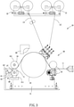
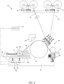
- the plastic flooring includes a substrate 11, a printing layer 12, and an anti-abrasion layer 13; and the device comprises a rolling unit 20 and an adjusting unit 60.
- the rolling unit 20 includes a press roller set 30, a first delivery roller set 21 configured to deliver the printing layer 12, and a second delivery roller set 22 configured to deliver the anti-abrasion layer 13.
- the press roller set is a well-known art and has four rollers which are arranged vertically.
- the press roller set includes at least four rollers which are arranged horizontally.
- the press roller set 30 includes five rollers which are arranged horizontally.
- the press roller set 30 has a first press roller 32, a second press roller 33, a third press roller 34, and a fourth press roller 35 which are all arranged on a base 31 horizontally.
- the press roller set 30 further includes a heater 39 arranged above the second press roller 33.
- the third press roller 34 has a pressing pattern section 341 formed on an outer wall thereof and configured to press a pattern area of the printing layer 12, thus producing pressing patterns on the pattern area of the printing layer 12.
- the substrate 11, the printing layer 12, and the anti-abrasion layer 13 are delivered toward the second press roller 33 so as to be pressed by the second press roller 33 and to be heated by the heater 39. Thereafter, the substrate 11, the printing layer 12, and the anti-abrasion layer 13 are pressed by the third press roller 34 and the fourth press roller 35, thus producing the plastic flooring having three-dimensional patterns.
- each of the third press roller 34 and the fourth press roller 35 is connected on a fixed segment 36, and each of a second end of each of the third press roller 34 and the fourth press roller 35 is connected on a movable segment 37.
- the adjusting unit 60 is fixed outside the movable segment 37, and the movable segment 37 is arranged based on a configuration of the third press roller 34 and the fourth press roller 35.
- the first end of the third press roller 34 is connected on the fixed segment 36 of the base 31, and the second end of the third press roller 34 is connected on an affix connector 71 of the movable segment 37, wherein the affix connector 71 is located on an extension 38 of the base 31.
- the adjusting unit 60 is located below the movable segment 37 of the base 31.
- the adjusting unit 60 is located outside or below the movable segment 37 of the base 31, a first end of the adjusting unit 60 is connected with the movable segment 37 so as to drive the movable segment 37 to move.
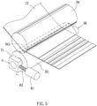
- the adjusting unit 60 includes at least one power source 61 and a movable rod 62 arranged on an end of the at least one power source 61, wherein the movable rod 62 is driven by the at least one power source 61 to urge the movable segment 37 to move, and the at least one power source 61 is manually or electrically controlled.
- the adjusting unit 60 when the adjusting unit 60 is located below the movable segment 37 of the third press roller 34, the adjusting unit 60 includes two power sources 61, wherein an end of each of the two power sources 61 is inserted through the base 31 to connect with the extension 38.
- each of the two power sources 61 is a gear box for accommodating a gear transmission mechanism, wherein one of the two power sources 61 has a drive lever 64 extending therefrom, the other power source 61' is connected with an actuation post 63, and a clutch element 65 is arranged on the actuation post 63 to drive two ends of the actuation post 63 to connect or remove.
- the drive lever 64 is rotated to actuate the two power sources 61, 61' to operate, and the movable segment 37 is actuated by the two power sources 61, 61' to lift and descend horizontally.
- each of the two power sources 61, 61' is a servo motor and is electrically connected with a controller 66, the controller 66 sends control signals to control the two power sources 61, 61' to operate, and the movable segment 37 is driven by the two power sources 61, 61' to move.
- a sole power source 61 is provided, and an end of the movable rod 62 is connected on an outer wall of the affix connector 71 so that when the sole power source 61 actuates the movable rod 62 to move, the movable segment 37 moves along the slide rail 311.
- the sole power source 61 is manually controlled and is a gear box, and the sole power source 61 has a drive lever 64' so that when the drive lever 64' is rotated to actuate the gear transmission mechanism of the sole power source 61 to operate, and the gear transmission mechanism drives the movable rod 62 to move.
- the adjusting unit 60 actuates the movable segment 37 to move so as to adjust the pattern area of the printing layer 12 to align with the pressing pattern section 341 of the third press roller 34.
- a first side of the printing layer 12 located on the fixed segment 36 is positioned, and a second side of the printing layer 12 located on the movable segment 37 is adjustably movable.
- the adjusting unit 60 actuates the movable segment 37 to move and to align with the pattern area of the printing layer 12, thus adjusting the registration of the plastic flooring.
- the adjusting unit 60 is electrically connected with an electronic control unit 50 of the registration system.
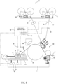
- the registration system includes a first sensor 41, a second sensor 42, a tension adjuster 43, and a third sensor 44.
- the first sensor 41 is a monitor or a camera which is fixed on a starting position of a delivery path of the printing layer 12. As shown in FIG. 7 , the printing layer 12 corresponds to the first sensor 41 and has multiple positioning origins 121 separated from each other, wherein a length between any two adjacent positioning origins 121 is set according to a circumference length of the third press roller 34 so as to form a print unit 122. In another embodiment, the circumference length of the third press roller 34 is more than a length of the print unit 122.
- the first sensor 41 is configured to detect each positioning origin 121 and sends detection information to the electronic control unit 50.
- the sensor 42 is configured to sense a rotation angle and a rotation position of the third press roller 34, the press roller 34 has at least one starting element 342, wherein the second sensor 42 sends sensed information of the at least one starting element 342 to the electronic control unit 50.
- the at least one starting element 342 is arranged on the outer wall of the press roller 34 and is a signal receiver, and the second sensor 42 transmits a light signal.
- the second sensor 42 transmits the light signal to the at least one starting element 342, and the at least one starting element 342 converts the light signal into sensed information and sends the sensed information to the electronic control unit 50.
- the tension adjuster 43 is arranged above a transporting end of the printing layer 12 so as to adjust a tension of the printing layer 12 when the printing layer 12 is delivered.
- the third sensor 44 is arranged outside the third press roller 34 and the fourth press roller 35 or is arranged on a delivery path of the plastic flooring so as to detect whether two positioning origins 121 on two sides of the printing layer 12 are on a same level or offset at an angle and to send sensing signals to the electronic control unit 50.
- the electronic control unit 50 is electrically connected with the rolling unit 20, the press roller set 30, the registration system, and the adjusting unit 60.
- the electronic control unit 50 includes a calculation module 51 so that when receiving the detection information of each positioning origin 121 of the printing layer 12, the calculation module 51 divides each positioning origin 121 (as shown in FIG. 8 ) into several parts based on a moving distance and a delivery speed between the starting position of the delivery path of the printing layer 12 and the third press roller 34 so as to establish transport simulations of the printing layer 12 and the third press roller 34.
- the calculation module 51 simulates and divides the circumference length of the third press roller 34 into several parts evenly, wherein a number of the several parts of each positioning origin 121 is equal to that of the circumference length of the third press roller 34, and the transport simulations of the printing layer 12 and the third press roller 34 are compared so as to judge whether the pattern area of the printing layer 12 aligns with the pressing pattern section 341 of the third press roller 34 when the third press roller 34 presses the substrate 11, the printing layer 12, and the anti-abrasion layer 13.
- the tension adjuster 43 adjusts the tension of the printing layer 12 so as to correct an error between the pattern area of the printing layer 12 and the pressing pattern section 341 of the third press roller 34.
- the electronic control unit 50 receives an offset signal of the printing layer 12, it calculates a deviation value of an angle of the printing layer 12 and controls the adjusting unit 60 to drive the movable segment 37 so that the movable segment 37 corrects the deviation value, thus aligning the pattern area of the printing layer 12 with the pressing pattern section 341 of the third press roller 34.
Landscapes
- Electroluminescent Light Sources (AREA)
- Shaping Of Tube Ends By Bending Or Straightening (AREA)
- Printing Methods (AREA)
Claims (6)
- Dispositif de réglage de l'alignement d'un revêtement de sol en plastique, le revêtement de sol en plastique comprenant un substrat (11), une couche d'impression (12) et une couche anti-abrasion (13), et le dispositif comprenant une unité de laminage (20) et une unité de réglage (60) ;l'unité de laminage (20) comprenant un ensemble de rouleaux presseurs (30), et l'ensemble de rouleaux presseurs (30) ayant un premier rouleau presseur (32), un deuxième rouleau presseur (33), un troisième rouleau presseur (34) et un quatrième rouleau presseur (35) ;dans lequel l'unité de laminage (20) est configurée pour distribuer un substrat (11), une couche d'impression (12) et une couche anti-abrasion (13) à l'ensemble de rouleaux presseurs (30) de telle sorte que le substrat (11), la couche d'impression (12) et la couche anti-abrasion (13) sont pressés à l'aide du troisième rouleau presseur (34) et du quatrième rouleau presseur (35) de l'ensemble de rouleaux presseurs (30) ;la couche d'impression (12) a une zone de motif, et le troisième rouleau presseur (34) a une section de motif de pression (341) formée sur une paroi extérieure de celui-ci et correspondant à la zone de motif de la couche d'impression (12) ;une première extrémité de chacun du troisième rouleau presseur (34) et du quatrième rouleau presseur (35) est connectée sur un segment fixe (36) d'une base (31), etle dispositif étant caractérisé par le fait que :chacune d'une seconde extrémité de chacun du troisième rouleau presseur (34) et du quatrième rouleau presseur (35) est connectée sur un segment mobile (37) de la base (31), l'unité de réglage (60) est fixée au-dessous du segment mobile (37) ;l'unité de réglage (60) comprend au moins une source d'énergie (61) et une tige mobile (62) disposée sur une extrémité de ladite au moins une source d'énergie (61), la tige mobile (62) étant entraînée par ladite au moins une source d'énergie (61) pour amener le segment mobile (37) à se déplacer ;lorsque la couche d'impression (12) se décale et que la zone de motif de la couche d'impression (12) ne s'aligne pas avec la section de motif de pression (341) après que le substrat (11), la couche d'impression (12) et la couche anti-abrasion (13) sont pressés ensemble par le troisième rouleau presseur (34) et le quatrième rouleau presseur (35), l'unité de réglage (60) actionne le segment mobile (37) pour qu'il se déplace de façon à régler la zone de motif de la couche d'impression (12) pour qu'elle s'aligne avec la section de motif de pression (341) du troisième rouleau presseur (34),dans lequel l'unité de réglage (60) est connectée électriquement à une unité de commande électronique (50) d'un système d'alignement, et le système d'alignement comprend un premier capteur (41), un deuxième capteur (42), un ajusteur de tension (43), un troisième capteur (44) et l'unité de commande électronique (50) ;dans lequel le premier capteur (41) est fixé sur une position de départ d'un trajet de distribution de la couche d'impression (12), la couche d'impression (12) correspond au premier capteur (41) et a plusieurs origines de positionnement (121) séparées entre elles, le premier capteur (41) étant configuré pour détecter chacune des différentes origines de positionnement (121) et envoyant des informations de détection à l'unité de commande électronique (50) ;dans lequel le capteur (42) est configuré pour détecter un angle de rotation et une position de rotation du troisième rouleau presseur (34), le rouleau presseur (34) a au moins un élément de démarrage (342), le deuxième capteur (42) envoyant des informations détectées dudit au moins un élément de démarrage (342) à l'unité de commande électronique (50) ;dans lequel l'ajusteur de tension (43) est disposé au-dessus d'une extrémité de transport de la couche d'impression (12) de façon à régler une tension de la couche d'impression (12) lorsque la couche d'impression (12) est distribuée ; etdans lequel le troisième capteur (44) est disposé à l'extérieur du troisième rouleau presseur (34) et du quatrième rouleau presseur (35) ou est disposé sur un trajet de distribution du revêtement de sol en plastique de façon à détecter si ou non deux origines de positionnement (121) sur deux côtés de la couche d'impression (12) sont sur un même niveau ou décalées angulairement et à envoyer des signaux de détection à l'unité de commande électronique (50) .
- Dispositif selon la revendication 1, caractérisé par le fait que, lorsque le troisième rouleau presseur (34) et le quatrième rouleau presseur (35) sont disposés horizontalement, la première extrémité du troisième rouleau presseur (34) est connectée sur le segment fixe (36) de la base (31), et la seconde extrémité du troisième rouleau presseur (34) est connectée sur un connecteur rattaché (71) du segment mobile (37), le connecteur rattaché (71) étant situé sur une extension (38) de la base (31), et l'unité de réglage (60) étant située au-dessous du segment mobile (37) de la base (31), l'unité de réglage (60) comprenant deux sources d'énergie (61), (61'), la tige mobile (62) de chacune des deux sources d'énergie (61), (61') étant introduite à travers la base (31) pour se connecter à l'extension (38).
- Dispositif selon la revendication 2, caractérisé par le fait que les deux sources d'énergie (61), (61') sont commandées manuellement, chacune des deux sources d'énergie (61), (61') étant une boîte de vitesse destinée à recevoir un mécanisme de transmission à engrenage, une source (61) des deux sources d'énergie (61), (61') ayant un levier d'entraînement (64) s'étendant à partir de celle-ci, l'autre source d'énergie (61') étant connectée à une tige d'actionnement (63), et un élément d'embrayage (65) étant disposé sur la tige d'actionnement (63) pour entraîner deux extrémités de la tige d'actionnement (63) pour brancher ou débrancher ; lorsque les deux extrémités de la tige d'actionnement (63) sont entraînées par l'élément d'embrayage (65) pour brancher, le levier d'entraînement (64) est entraîné en rotation pour amener les deux sources d'énergie (61), (61') à fonctionner, et, lorsque les deux extrémités de la tige d'actionnement (63) sont entraînées par l'élément d'embrayage (65) pour débrancher, le levier d'entraînement (64) est entraîné en rotation pour amener l'une des deux sources d'énergie (61), (61') à fonctionner.
- Dispositif selon la revendication 1, caractérisé par le fait que, lorsque le troisième rouleau presseur (34) et le quatrième rouleau presseur (35) sont disposés verticalement, une première extrémité du quatrième rouleau presseur (35) est connectée sur le segment fixe (36) de la base (31), et une seconde extrémité du quatrième rouleau presseur (35) est connectée sur un connecteur rattaché (71) du segment mobile (37), le connecteur rattaché (71) étant situé sur une extension (38'), et la base (31) ayant un rail de glissement (311) correspondant à une partie inférieure de l'extension (38') et retenu par celle-ci ; l'unité de réglage (60) est disposée à l'extérieur du segment mobile (37), et une extrémité de la tige mobile (62) de ladite au moins une source d'énergie (61) est connectée sur une paroi extérieure du connecteur rattaché (71) de telle sorte que, lorsque ladite au moins une source d'énergie (61) amène la tige mobile (62) à se déplacer, le segment mobile (37) se déplace le long du rail de glissement (311).
- Dispositif selon la revendication 4, caractérisé par le fait que ladite au moins une source d'énergie (61) est commandée manuellement et est une boîte de vitesse, et ladite au moins une source d'énergie (61) a un levier d'entraînement (64') de telle sorte que, lorsque le levier d'entraînement (64') est entraîné à en rotation pour amener ladite au moins une source d'énergie (61) à fonctionner, ladite au moins une source d'énergie (61) amène la tige mobile (62) à se déplacer.
- Dispositif selon la revendication 2, caractérisé par le fait que, lorsque l'unité de réglage (60) est commandée électriquement, chacune des deux sources d'énergie (61), (61') est un servomoteur et est connectée électriquement à un contrôleur (66), et le contrôleur (66) commande le fonctionnement des deux sources d'énergie (61), (61').
Priority Applications (5)
| Application Number | Priority Date | Filing Date | Title |
|---|---|---|---|
| ES19162681T ES2911634T3 (es) | 2019-03-13 | 2019-03-13 | Dispositivo de ajuste de registro de suelo de plástico |
| EP22154475.2A EP4026695A1 (fr) | 2019-03-13 | 2019-03-13 | Dispositif d'ajustement de l'alignement d'un revêtement de sol en plastique |
| PT191626811T PT3708366T (pt) | 2019-03-13 | 2019-03-13 | Dispositivo de ajuste de alinhamento de pavimentos de plástico |
| EP19162681.1A EP3708366B1 (fr) | 2019-03-13 | 2019-03-13 | Dispositif d'ajustement de l'alignement d'un revêtement de sol en plastique |
| PL19162681T PL3708366T3 (pl) | 2019-03-13 | 2019-03-13 | Urządzenie do regulacji registra wykładziny podłogowej z tworzywa sztucznego |
Applications Claiming Priority (1)
| Application Number | Priority Date | Filing Date | Title |
|---|---|---|---|
| EP19162681.1A EP3708366B1 (fr) | 2019-03-13 | 2019-03-13 | Dispositif d'ajustement de l'alignement d'un revêtement de sol en plastique |
Related Child Applications (1)
| Application Number | Title | Priority Date | Filing Date |
|---|---|---|---|
| EP22154475.2A Division EP4026695A1 (fr) | 2019-03-13 | 2019-03-13 | Dispositif d'ajustement de l'alignement d'un revêtement de sol en plastique |
Publications (2)
| Publication Number | Publication Date |
|---|---|
| EP3708366A1 EP3708366A1 (fr) | 2020-09-16 |
| EP3708366B1 true EP3708366B1 (fr) | 2022-02-02 |
Family
ID=65812113
Family Applications (2)
| Application Number | Title | Priority Date | Filing Date |
|---|---|---|---|
| EP22154475.2A Withdrawn EP4026695A1 (fr) | 2019-03-13 | 2019-03-13 | Dispositif d'ajustement de l'alignement d'un revêtement de sol en plastique |
| EP19162681.1A Active EP3708366B1 (fr) | 2019-03-13 | 2019-03-13 | Dispositif d'ajustement de l'alignement d'un revêtement de sol en plastique |
Family Applications Before (1)
| Application Number | Title | Priority Date | Filing Date |
|---|---|---|---|
| EP22154475.2A Withdrawn EP4026695A1 (fr) | 2019-03-13 | 2019-03-13 | Dispositif d'ajustement de l'alignement d'un revêtement de sol en plastique |
Country Status (4)
| Country | Link |
|---|---|
| EP (2) | EP4026695A1 (fr) |
| ES (1) | ES2911634T3 (fr) |
| PL (1) | PL3708366T3 (fr) |
| PT (1) | PT3708366T (fr) |
Family Cites Families (3)
| Publication number | Priority date | Publication date | Assignee | Title |
|---|---|---|---|---|
| DE102014101554A1 (de) * | 2013-10-16 | 2015-04-16 | Olbrich Gmbh | Verfahren und Vorrichtung zur Herstellung eines registerhaltig geprägten, insbesondere laminierten, Verbundmaterials |
| US11633905B2 (en) * | 2016-06-15 | 2023-04-25 | Flooring Industries Limited, Sarl | Long decorative material with embossing in register with pattern and rolling method and device therefor |
| PL3308952T3 (pl) * | 2016-10-12 | 2020-06-29 | Ding Yi Lu | Wykładzina podłogowa z tworzyw sztucznych z wzorami rejestracyjnymi |
-
2019
- 2019-03-13 ES ES19162681T patent/ES2911634T3/es active Active
- 2019-03-13 EP EP22154475.2A patent/EP4026695A1/fr not_active Withdrawn
- 2019-03-13 PL PL19162681T patent/PL3708366T3/pl unknown
- 2019-03-13 EP EP19162681.1A patent/EP3708366B1/fr active Active
- 2019-03-13 PT PT191626811T patent/PT3708366T/pt unknown
Also Published As
| Publication number | Publication date |
|---|---|
| PL3708366T3 (pl) | 2022-06-20 |
| EP3708366A1 (fr) | 2020-09-16 |
| ES2911634T3 (es) | 2022-05-20 |
| PT3708366T (pt) | 2022-05-11 |
| EP4026695A1 (fr) | 2022-07-13 |
Similar Documents
| Publication | Publication Date | Title |
|---|---|---|
| US10940637B2 (en) | Process for producing a surface covering with an embossed printed surface | |
| CN209888141U (zh) | 塑胶地板的对花调整装置 | |
| EP3515710B1 (fr) | Appareil d'estampage en registre de feuille et procédé | |
| CN109940867B (zh) | 改进的塑料地板的同步对花系统 | |
| ITUB20152764A1 (it) | Procedimenti per la cordonatura e taglio di materiali in fogli. | |
| KR20120103647A (ko) | 담배 팁의 팁 커버 엠보싱 방법 | |
| EP3308952B1 (fr) | Revêtement de sol en plastique présentant des motifs d'enregistrement | |
| US10723114B1 (en) | Device of adjusting registration of plastic flooring | |
| CN113766736A (zh) | 薄膜处理系统和方法 | |
| JP2023540939A (ja) | 印刷方法及びシステム | |
| JP5038173B2 (ja) | 印刷フイルムラミネート枚葉紙製造装置 | |
| US10695971B2 (en) | Plastic flooring having registration system | |
| US10384427B2 (en) | Plastic flooring having registration patterns | |
| CN113766735A (zh) | 薄膜处理系统和方法 | |
| JP2005132017A (ja) | 追刷り印刷の位置合わせ方法及び追刷り印刷装置 | |
| US20110285974A1 (en) | Printer | |
| EP3708366A1 (fr) | Dispositif d'ajustement de l'alignement d'un revêtement de sol en plastique | |
| JP2000246881A (ja) | 多色刷り印刷金属板の製造方法およびその印刷装置 | |
| EP3708367B1 (fr) | Équipement pour fabriquer un revêtement de sol en plastique | |
| KR20050110488A (ko) | 감열방식 프린터의 슬립 보상방법 | |
| KR20130008214A (ko) | 롤투롤 인쇄의 박막 링클 생성 제어 장치 및 이의 제어 방법 | |
| CN213368229U (zh) | 薄膜处理系统 | |
| CN111516252B (zh) | 塑胶地板的对花调整装置 | |
| CN116766762B (zh) | 轮转式印刷设备及其方法 | |
| KR101689027B1 (ko) | 책자형 인쇄물의 표지 인쇄기 |
Legal Events
| Date | Code | Title | Description |
|---|---|---|---|
| PUAI | Public reference made under article 153(3) epc to a published international application that has entered the european phase |
Free format text: ORIGINAL CODE: 0009012 |
|
| STAA | Information on the status of an ep patent application or granted ep patent |
Free format text: STATUS: THE APPLICATION HAS BEEN PUBLISHED |
|
| AK | Designated contracting states |
Kind code of ref document: A1 Designated state(s): AL AT BE BG CH CY CZ DE DK EE ES FI FR GB GR HR HU IE IS IT LI LT LU LV MC MK MT NL NO PL PT RO RS SE SI SK SM TR |
|
| AX | Request for extension of the european patent |
Extension state: BA ME |
|
| STAA | Information on the status of an ep patent application or granted ep patent |
Free format text: STATUS: REQUEST FOR EXAMINATION WAS MADE |
|
| 17P | Request for examination filed |
Effective date: 20210312 |
|
| RBV | Designated contracting states (corrected) |
Designated state(s): AL AT BE BG CH CY CZ DE DK EE ES FI FR GB GR HR HU IE IS IT LI LT LU LV MC MK MT NL NO PL PT RO RS SE SI SK SM TR |
|
| GRAP | Despatch of communication of intention to grant a patent |
Free format text: ORIGINAL CODE: EPIDOSNIGR1 |
|
| STAA | Information on the status of an ep patent application or granted ep patent |
Free format text: STATUS: GRANT OF PATENT IS INTENDED |
|
| RIC1 | Information provided on ipc code assigned before grant |
Ipc: B32B 41/00 20060101ALI20210805BHEP Ipc: B32B 38/06 20060101AFI20210805BHEP |
|
| INTG | Intention to grant announced |
Effective date: 20210824 |
|
| GRAS | Grant fee paid |
Free format text: ORIGINAL CODE: EPIDOSNIGR3 |
|
| GRAA | (expected) grant |
Free format text: ORIGINAL CODE: 0009210 |
|
| STAA | Information on the status of an ep patent application or granted ep patent |
Free format text: STATUS: THE PATENT HAS BEEN GRANTED |
|
| AK | Designated contracting states |
Kind code of ref document: B1 Designated state(s): AL AT BE BG CH CY CZ DE DK EE ES FI FR GB GR HR HU IE IS IT LI LT LU LV MC MK MT NL NO PL PT RO RS SE SI SK SM TR |
|
| REG | Reference to a national code |
Ref country code: GB Ref legal event code: FG4D |
|
| REG | Reference to a national code |
Ref country code: CH Ref legal event code: EP Ref country code: AT Ref legal event code: REF Ref document number: 1466487 Country of ref document: AT Kind code of ref document: T Effective date: 20220215 |
|
| REG | Reference to a national code |
Ref country code: DE Ref legal event code: R096 Ref document number: 602019011323 Country of ref document: DE |
|
| REG | Reference to a national code |
Ref country code: IE Ref legal event code: FG4D |
|
| REG | Reference to a national code |
Ref country code: NL Ref legal event code: FP |
|
| REG | Reference to a national code |
Ref country code: PT Ref legal event code: SC4A Ref document number: 3708366 Country of ref document: PT Date of ref document: 20220511 Kind code of ref document: T Free format text: AVAILABILITY OF NATIONAL TRANSLATION Effective date: 20220502 |
|
| REG | Reference to a national code |
Ref country code: ES Ref legal event code: FG2A Ref document number: 2911634 Country of ref document: ES Kind code of ref document: T3 Effective date: 20220520 |
|
| REG | Reference to a national code |
Ref country code: LT Ref legal event code: MG9D |
|
| REG | Reference to a national code |
Ref country code: AT Ref legal event code: MK05 Ref document number: 1466487 Country of ref document: AT Kind code of ref document: T Effective date: 20220202 |
|
| PG25 | Lapsed in a contracting state [announced via postgrant information from national office to epo] |
Ref country code: SE Free format text: LAPSE BECAUSE OF FAILURE TO SUBMIT A TRANSLATION OF THE DESCRIPTION OR TO PAY THE FEE WITHIN THE PRESCRIBED TIME-LIMIT Effective date: 20220202 Ref country code: RS Free format text: LAPSE BECAUSE OF FAILURE TO SUBMIT A TRANSLATION OF THE DESCRIPTION OR TO PAY THE FEE WITHIN THE PRESCRIBED TIME-LIMIT Effective date: 20220202 Ref country code: NO Free format text: LAPSE BECAUSE OF FAILURE TO SUBMIT A TRANSLATION OF THE DESCRIPTION OR TO PAY THE FEE WITHIN THE PRESCRIBED TIME-LIMIT Effective date: 20220502 Ref country code: LT Free format text: LAPSE BECAUSE OF FAILURE TO SUBMIT A TRANSLATION OF THE DESCRIPTION OR TO PAY THE FEE WITHIN THE PRESCRIBED TIME-LIMIT Effective date: 20220202 Ref country code: HR Free format text: LAPSE BECAUSE OF FAILURE TO SUBMIT A TRANSLATION OF THE DESCRIPTION OR TO PAY THE FEE WITHIN THE PRESCRIBED TIME-LIMIT Effective date: 20220202 Ref country code: BG Free format text: LAPSE BECAUSE OF FAILURE TO SUBMIT A TRANSLATION OF THE DESCRIPTION OR TO PAY THE FEE WITHIN THE PRESCRIBED TIME-LIMIT Effective date: 20220502 |
|
| PG25 | Lapsed in a contracting state [announced via postgrant information from national office to epo] |
Ref country code: LV Free format text: LAPSE BECAUSE OF FAILURE TO SUBMIT A TRANSLATION OF THE DESCRIPTION OR TO PAY THE FEE WITHIN THE PRESCRIBED TIME-LIMIT Effective date: 20220202 Ref country code: GR Free format text: LAPSE BECAUSE OF FAILURE TO SUBMIT A TRANSLATION OF THE DESCRIPTION OR TO PAY THE FEE WITHIN THE PRESCRIBED TIME-LIMIT Effective date: 20220503 Ref country code: FI Free format text: LAPSE BECAUSE OF FAILURE TO SUBMIT A TRANSLATION OF THE DESCRIPTION OR TO PAY THE FEE WITHIN THE PRESCRIBED TIME-LIMIT Effective date: 20220202 Ref country code: AT Free format text: LAPSE BECAUSE OF FAILURE TO SUBMIT A TRANSLATION OF THE DESCRIPTION OR TO PAY THE FEE WITHIN THE PRESCRIBED TIME-LIMIT Effective date: 20220202 |
|
| PG25 | Lapsed in a contracting state [announced via postgrant information from national office to epo] |
Ref country code: IS Free format text: LAPSE BECAUSE OF FAILURE TO SUBMIT A TRANSLATION OF THE DESCRIPTION OR TO PAY THE FEE WITHIN THE PRESCRIBED TIME-LIMIT Effective date: 20220602 |
|
| PG25 | Lapsed in a contracting state [announced via postgrant information from national office to epo] |
Ref country code: SM Free format text: LAPSE BECAUSE OF FAILURE TO SUBMIT A TRANSLATION OF THE DESCRIPTION OR TO PAY THE FEE WITHIN THE PRESCRIBED TIME-LIMIT Effective date: 20220202 Ref country code: SK Free format text: LAPSE BECAUSE OF FAILURE TO SUBMIT A TRANSLATION OF THE DESCRIPTION OR TO PAY THE FEE WITHIN THE PRESCRIBED TIME-LIMIT Effective date: 20220202 Ref country code: RO Free format text: LAPSE BECAUSE OF FAILURE TO SUBMIT A TRANSLATION OF THE DESCRIPTION OR TO PAY THE FEE WITHIN THE PRESCRIBED TIME-LIMIT Effective date: 20220202 Ref country code: EE Free format text: LAPSE BECAUSE OF FAILURE TO SUBMIT A TRANSLATION OF THE DESCRIPTION OR TO PAY THE FEE WITHIN THE PRESCRIBED TIME-LIMIT Effective date: 20220202 Ref country code: DK Free format text: LAPSE BECAUSE OF FAILURE TO SUBMIT A TRANSLATION OF THE DESCRIPTION OR TO PAY THE FEE WITHIN THE PRESCRIBED TIME-LIMIT Effective date: 20220202 Ref country code: CZ Free format text: LAPSE BECAUSE OF FAILURE TO SUBMIT A TRANSLATION OF THE DESCRIPTION OR TO PAY THE FEE WITHIN THE PRESCRIBED TIME-LIMIT Effective date: 20220202 |
|
| REG | Reference to a national code |
Ref country code: DE Ref legal event code: R097 Ref document number: 602019011323 Country of ref document: DE |
|
| PG25 | Lapsed in a contracting state [announced via postgrant information from national office to epo] |
Ref country code: MC Free format text: LAPSE BECAUSE OF FAILURE TO SUBMIT A TRANSLATION OF THE DESCRIPTION OR TO PAY THE FEE WITHIN THE PRESCRIBED TIME-LIMIT Effective date: 20220202 Ref country code: AL Free format text: LAPSE BECAUSE OF FAILURE TO SUBMIT A TRANSLATION OF THE DESCRIPTION OR TO PAY THE FEE WITHIN THE PRESCRIBED TIME-LIMIT Effective date: 20220202 |
|
| PLBE | No opposition filed within time limit |
Free format text: ORIGINAL CODE: 0009261 |
|
| STAA | Information on the status of an ep patent application or granted ep patent |
Free format text: STATUS: NO OPPOSITION FILED WITHIN TIME LIMIT |
|
| 26N | No opposition filed |
Effective date: 20221103 |
|
| PG25 | Lapsed in a contracting state [announced via postgrant information from national office to epo] |
Ref country code: IE Free format text: LAPSE BECAUSE OF NON-PAYMENT OF DUE FEES Effective date: 20220313 |
|
| PG25 | Lapsed in a contracting state [announced via postgrant information from national office to epo] |
Ref country code: SI Free format text: LAPSE BECAUSE OF FAILURE TO SUBMIT A TRANSLATION OF THE DESCRIPTION OR TO PAY THE FEE WITHIN THE PRESCRIBED TIME-LIMIT Effective date: 20220202 |
|
| PG25 | Lapsed in a contracting state [announced via postgrant information from national office to epo] |
Ref country code: IT Free format text: LAPSE BECAUSE OF FAILURE TO SUBMIT A TRANSLATION OF THE DESCRIPTION OR TO PAY THE FEE WITHIN THE PRESCRIBED TIME-LIMIT Effective date: 20220202 |
|
| PG25 | Lapsed in a contracting state [announced via postgrant information from national office to epo] |
Ref country code: MK Free format text: LAPSE BECAUSE OF FAILURE TO SUBMIT A TRANSLATION OF THE DESCRIPTION OR TO PAY THE FEE WITHIN THE PRESCRIBED TIME-LIMIT Effective date: 20220202 Ref country code: CY Free format text: LAPSE BECAUSE OF FAILURE TO SUBMIT A TRANSLATION OF THE DESCRIPTION OR TO PAY THE FEE WITHIN THE PRESCRIBED TIME-LIMIT Effective date: 20220202 |
|
| PG25 | Lapsed in a contracting state [announced via postgrant information from national office to epo] |
Ref country code: HU Free format text: LAPSE BECAUSE OF FAILURE TO SUBMIT A TRANSLATION OF THE DESCRIPTION OR TO PAY THE FEE WITHIN THE PRESCRIBED TIME-LIMIT; INVALID AB INITIO Effective date: 20190313 |
|
| PG25 | Lapsed in a contracting state [announced via postgrant information from national office to epo] |
Ref country code: MT Free format text: LAPSE BECAUSE OF FAILURE TO SUBMIT A TRANSLATION OF THE DESCRIPTION OR TO PAY THE FEE WITHIN THE PRESCRIBED TIME-LIMIT Effective date: 20220202 |
|
| PGFP | Annual fee paid to national office [announced via postgrant information from national office to epo] |
Ref country code: ES Payment date: 20250410 Year of fee payment: 7 |
|
| PGFP | Annual fee paid to national office [announced via postgrant information from national office to epo] |
Ref country code: CH Payment date: 20250401 Year of fee payment: 7 |
|
| PGFP | Annual fee paid to national office [announced via postgrant information from national office to epo] |
Ref country code: NL Payment date: 20260226 Year of fee payment: 8 Ref country code: LU Payment date: 20260226 Year of fee payment: 8 |
|
| REG | Reference to a national code |
Ref country code: CH Ref legal event code: U11 Free format text: ST27 STATUS EVENT CODE: U-0-0-U10-U11 (AS PROVIDED BY THE NATIONAL OFFICE) Effective date: 20260401 |
|
| PGFP | Annual fee paid to national office [announced via postgrant information from national office to epo] |
Ref country code: GB Payment date: 20260116 Year of fee payment: 8 |
|
| PGFP | Annual fee paid to national office [announced via postgrant information from national office to epo] |
Ref country code: DE Payment date: 20260313 Year of fee payment: 8 |
|
| PGFP | Annual fee paid to national office [announced via postgrant information from national office to epo] |
Ref country code: BE Payment date: 20260324 Year of fee payment: 8 |
|
| PGFP | Annual fee paid to national office [announced via postgrant information from national office to epo] |
Ref country code: FR Payment date: 20260116 Year of fee payment: 8 |
|
| PGFP | Annual fee paid to national office [announced via postgrant information from national office to epo] |
Ref country code: TR Payment date: 20260304 Year of fee payment: 8 |
|
| PGFP | Annual fee paid to national office [announced via postgrant information from national office to epo] |
Ref country code: PT Payment date: 20260114 Year of fee payment: 8 |
|
| PGFP | Annual fee paid to national office [announced via postgrant information from national office to epo] |
Ref country code: PL Payment date: 20260120 Year of fee payment: 8 |