EP3708354A1 - Cardboard box dividing device and cardboard box manufacturing device - Google Patents
Cardboard box dividing device and cardboard box manufacturing device Download PDFInfo
- Publication number
- EP3708354A1 EP3708354A1 EP18888611.3A EP18888611A EP3708354A1 EP 3708354 A1 EP3708354 A1 EP 3708354A1 EP 18888611 A EP18888611 A EP 18888611A EP 3708354 A1 EP3708354 A1 EP 3708354A1
- Authority
- EP
- European Patent Office
- Prior art keywords
- cardboard box
- positioning member
- side positioning
- downstream side
- lifting
- Prior art date
- Legal status (The legal status is an assumption and is not a legal conclusion. Google has not performed a legal analysis and makes no representation as to the accuracy of the status listed.)
- Granted
Links
Images














Classifications
-
- B—PERFORMING OPERATIONS; TRANSPORTING
- B31—MAKING ARTICLES OF PAPER, CARDBOARD OR MATERIAL WORKED IN A MANNER ANALOGOUS TO PAPER; WORKING PAPER, CARDBOARD OR MATERIAL WORKED IN A MANNER ANALOGOUS TO PAPER
- B31B—MAKING CONTAINERS OF PAPER, CARDBOARD OR MATERIAL WORKED IN A MANNER ANALOGOUS TO PAPER
- B31B50/00—Making rigid or semi-rigid containers, e.g. boxes or cartons
- B31B50/14—Cutting, e.g. perforating, punching, slitting or trimming
- B31B50/20—Cutting sheets or blanks
-
- B—PERFORMING OPERATIONS; TRANSPORTING
- B26—HAND CUTTING TOOLS; CUTTING; SEVERING
- B26D—CUTTING; DETAILS COMMON TO MACHINES FOR PERFORATING, PUNCHING, CUTTING-OUT, STAMPING-OUT OR SEVERING
- B26D1/00—Cutting through work characterised by the nature or movement of the cutting member or particular materials not otherwise provided for; Apparatus or machines therefor; Cutting members therefor
- B26D1/01—Cutting through work characterised by the nature or movement of the cutting member or particular materials not otherwise provided for; Apparatus or machines therefor; Cutting members therefor involving a cutting member which does not travel with the work
- B26D1/02—Cutting through work characterised by the nature or movement of the cutting member or particular materials not otherwise provided for; Apparatus or machines therefor; Cutting members therefor involving a cutting member which does not travel with the work having a stationary cutting member
- B26D1/025—Cutting through work characterised by the nature or movement of the cutting member or particular materials not otherwise provided for; Apparatus or machines therefor; Cutting members therefor involving a cutting member which does not travel with the work having a stationary cutting member for thin material, e.g. for sheets, strips or the like
-
- B—PERFORMING OPERATIONS; TRANSPORTING
- B26—HAND CUTTING TOOLS; CUTTING; SEVERING
- B26D—CUTTING; DETAILS COMMON TO MACHINES FOR PERFORATING, PUNCHING, CUTTING-OUT, STAMPING-OUT OR SEVERING
- B26D1/00—Cutting through work characterised by the nature or movement of the cutting member or particular materials not otherwise provided for; Apparatus or machines therefor; Cutting members therefor
- B26D1/01—Cutting through work characterised by the nature or movement of the cutting member or particular materials not otherwise provided for; Apparatus or machines therefor; Cutting members therefor involving a cutting member which does not travel with the work
- B26D1/04—Cutting through work characterised by the nature or movement of the cutting member or particular materials not otherwise provided for; Apparatus or machines therefor; Cutting members therefor involving a cutting member which does not travel with the work having a linearly-movable cutting member
- B26D1/06—Cutting through work characterised by the nature or movement of the cutting member or particular materials not otherwise provided for; Apparatus or machines therefor; Cutting members therefor involving a cutting member which does not travel with the work having a linearly-movable cutting member wherein the cutting member reciprocates
- B26D1/08—Cutting through work characterised by the nature or movement of the cutting member or particular materials not otherwise provided for; Apparatus or machines therefor; Cutting members therefor involving a cutting member which does not travel with the work having a linearly-movable cutting member wherein the cutting member reciprocates of the guillotine type
- B26D1/085—Cutting through work characterised by the nature or movement of the cutting member or particular materials not otherwise provided for; Apparatus or machines therefor; Cutting members therefor involving a cutting member which does not travel with the work having a linearly-movable cutting member wherein the cutting member reciprocates of the guillotine type for thin material, e.g. for sheets, strips or the like
-
- B—PERFORMING OPERATIONS; TRANSPORTING
- B26—HAND CUTTING TOOLS; CUTTING; SEVERING
- B26D—CUTTING; DETAILS COMMON TO MACHINES FOR PERFORATING, PUNCHING, CUTTING-OUT, STAMPING-OUT OR SEVERING
- B26D1/00—Cutting through work characterised by the nature or movement of the cutting member or particular materials not otherwise provided for; Apparatus or machines therefor; Cutting members therefor
- B26D1/01—Cutting through work characterised by the nature or movement of the cutting member or particular materials not otherwise provided for; Apparatus or machines therefor; Cutting members therefor involving a cutting member which does not travel with the work
- B26D1/46—Cutting through work characterised by the nature or movement of the cutting member or particular materials not otherwise provided for; Apparatus or machines therefor; Cutting members therefor involving a cutting member which does not travel with the work having an endless band-knife or the like
- B26D1/465—Cutting through work characterised by the nature or movement of the cutting member or particular materials not otherwise provided for; Apparatus or machines therefor; Cutting members therefor involving a cutting member which does not travel with the work having an endless band-knife or the like for thin material, e.g. for sheets, strips or the like
-
- B—PERFORMING OPERATIONS; TRANSPORTING
- B26—HAND CUTTING TOOLS; CUTTING; SEVERING
- B26D—CUTTING; DETAILS COMMON TO MACHINES FOR PERFORATING, PUNCHING, CUTTING-OUT, STAMPING-OUT OR SEVERING
- B26D7/00—Details of apparatus for cutting, cutting-out, stamping-out, punching, perforating, or severing by means other than cutting
- B26D7/01—Means for holding or positioning work
- B26D7/015—Means for holding or positioning work for sheet material or piles of sheets
-
- B—PERFORMING OPERATIONS; TRANSPORTING
- B31—MAKING ARTICLES OF PAPER, CARDBOARD OR MATERIAL WORKED IN A MANNER ANALOGOUS TO PAPER; WORKING PAPER, CARDBOARD OR MATERIAL WORKED IN A MANNER ANALOGOUS TO PAPER
- B31B—MAKING CONTAINERS OF PAPER, CARDBOARD OR MATERIAL WORKED IN A MANNER ANALOGOUS TO PAPER
- B31B50/00—Making rigid or semi-rigid containers, e.g. boxes or cartons
- B31B50/005—Making rigid or semi-rigid containers, e.g. boxes or cartons involving a particular layout of the machinery or relative arrangement of its subunits
-
- B—PERFORMING OPERATIONS; TRANSPORTING
- B31—MAKING ARTICLES OF PAPER, CARDBOARD OR MATERIAL WORKED IN A MANNER ANALOGOUS TO PAPER; WORKING PAPER, CARDBOARD OR MATERIAL WORKED IN A MANNER ANALOGOUS TO PAPER
- B31B—MAKING CONTAINERS OF PAPER, CARDBOARD OR MATERIAL WORKED IN A MANNER ANALOGOUS TO PAPER
- B31B50/00—Making rigid or semi-rigid containers, e.g. boxes or cartons
- B31B50/02—Feeding or positioning sheets, blanks or webs
- B31B50/04—Feeding sheets or blanks
- B31B50/06—Feeding sheets or blanks from stacks
-
- B—PERFORMING OPERATIONS; TRANSPORTING
- B31—MAKING ARTICLES OF PAPER, CARDBOARD OR MATERIAL WORKED IN A MANNER ANALOGOUS TO PAPER; WORKING PAPER, CARDBOARD OR MATERIAL WORKED IN A MANNER ANALOGOUS TO PAPER
- B31B—MAKING CONTAINERS OF PAPER, CARDBOARD OR MATERIAL WORKED IN A MANNER ANALOGOUS TO PAPER
- B31B50/00—Making rigid or semi-rigid containers, e.g. boxes or cartons
- B31B50/25—Surface scoring
- B31B50/256—Surface scoring using tools mounted on a drum
-
- B—PERFORMING OPERATIONS; TRANSPORTING
- B31—MAKING ARTICLES OF PAPER, CARDBOARD OR MATERIAL WORKED IN A MANNER ANALOGOUS TO PAPER; WORKING PAPER, CARDBOARD OR MATERIAL WORKED IN A MANNER ANALOGOUS TO PAPER
- B31B—MAKING CONTAINERS OF PAPER, CARDBOARD OR MATERIAL WORKED IN A MANNER ANALOGOUS TO PAPER
- B31B50/00—Making rigid or semi-rigid containers, e.g. boxes or cartons
- B31B50/26—Folding sheets, blanks or webs
-
- B—PERFORMING OPERATIONS; TRANSPORTING
- B31—MAKING ARTICLES OF PAPER, CARDBOARD OR MATERIAL WORKED IN A MANNER ANALOGOUS TO PAPER; WORKING PAPER, CARDBOARD OR MATERIAL WORKED IN A MANNER ANALOGOUS TO PAPER
- B31B—MAKING CONTAINERS OF PAPER, CARDBOARD OR MATERIAL WORKED IN A MANNER ANALOGOUS TO PAPER
- B31B50/00—Making rigid or semi-rigid containers, e.g. boxes or cartons
- B31B50/60—Uniting opposed surfaces or edges; Taping
- B31B50/62—Uniting opposed surfaces or edges; Taping by adhesives
- B31B50/624—Applying glue on blanks
-
- B—PERFORMING OPERATIONS; TRANSPORTING
- B31—MAKING ARTICLES OF PAPER, CARDBOARD OR MATERIAL WORKED IN A MANNER ANALOGOUS TO PAPER; WORKING PAPER, CARDBOARD OR MATERIAL WORKED IN A MANNER ANALOGOUS TO PAPER
- B31B—MAKING CONTAINERS OF PAPER, CARDBOARD OR MATERIAL WORKED IN A MANNER ANALOGOUS TO PAPER
- B31B50/00—Making rigid or semi-rigid containers, e.g. boxes or cartons
- B31B50/74—Auxiliary operations
- B31B50/92—Delivering
- B31B50/98—Delivering in stacks or bundles
-
- B—PERFORMING OPERATIONS; TRANSPORTING
- B26—HAND CUTTING TOOLS; CUTTING; SEVERING
- B26D—CUTTING; DETAILS COMMON TO MACHINES FOR PERFORATING, PUNCHING, CUTTING-OUT, STAMPING-OUT OR SEVERING
- B26D7/00—Details of apparatus for cutting, cutting-out, stamping-out, punching, perforating, or severing by means other than cutting
- B26D7/27—Means for performing other operations combined with cutting
- B26D7/32—Means for performing other operations combined with cutting for conveying or stacking cut product
- B26D2007/322—Means for performing other operations combined with cutting for conveying or stacking cut product the cut products being sheets, e.g. sheets of paper
-
- B—PERFORMING OPERATIONS; TRANSPORTING
- B26—HAND CUTTING TOOLS; CUTTING; SEVERING
- B26D—CUTTING; DETAILS COMMON TO MACHINES FOR PERFORATING, PUNCHING, CUTTING-OUT, STAMPING-OUT OR SEVERING
- B26D7/00—Details of apparatus for cutting, cutting-out, stamping-out, punching, perforating, or severing by means other than cutting
- B26D7/06—Arrangements for feeding or delivering work of other than sheet, web, or filamentary form
- B26D7/0675—Arrangements for feeding or delivering work of other than sheet, web, or filamentary form specially adapted for piles of sheets
-
- B—PERFORMING OPERATIONS; TRANSPORTING
- B31—MAKING ARTICLES OF PAPER, CARDBOARD OR MATERIAL WORKED IN A MANNER ANALOGOUS TO PAPER; WORKING PAPER, CARDBOARD OR MATERIAL WORKED IN A MANNER ANALOGOUS TO PAPER
- B31B—MAKING CONTAINERS OF PAPER, CARDBOARD OR MATERIAL WORKED IN A MANNER ANALOGOUS TO PAPER
- B31B2110/00—Shape of rigid or semi-rigid containers
- B31B2110/30—Shape of rigid or semi-rigid containers having a polygonal cross section
- B31B2110/35—Shape of rigid or semi-rigid containers having a polygonal cross section rectangular, e.g. square
-
- B—PERFORMING OPERATIONS; TRANSPORTING
- B31—MAKING ARTICLES OF PAPER, CARDBOARD OR MATERIAL WORKED IN A MANNER ANALOGOUS TO PAPER; WORKING PAPER, CARDBOARD OR MATERIAL WORKED IN A MANNER ANALOGOUS TO PAPER
- B31B—MAKING CONTAINERS OF PAPER, CARDBOARD OR MATERIAL WORKED IN A MANNER ANALOGOUS TO PAPER
- B31B2120/00—Construction of rigid or semi-rigid containers
- B31B2120/30—Construction of rigid or semi-rigid containers collapsible; temporarily collapsed during manufacturing
- B31B2120/302—Construction of rigid or semi-rigid containers collapsible; temporarily collapsed during manufacturing collapsible into a flat condition
-
- B—PERFORMING OPERATIONS; TRANSPORTING
- B31—MAKING ARTICLES OF PAPER, CARDBOARD OR MATERIAL WORKED IN A MANNER ANALOGOUS TO PAPER; WORKING PAPER, CARDBOARD OR MATERIAL WORKED IN A MANNER ANALOGOUS TO PAPER
- B31B—MAKING CONTAINERS OF PAPER, CARDBOARD OR MATERIAL WORKED IN A MANNER ANALOGOUS TO PAPER
- B31B50/00—Making rigid or semi-rigid containers, e.g. boxes or cartons
- B31B50/14—Cutting, e.g. perforating, punching, slitting or trimming
- B31B50/142—Cutting, e.g. perforating, punching, slitting or trimming using presses or dies
-
- B—PERFORMING OPERATIONS; TRANSPORTING
- B31—MAKING ARTICLES OF PAPER, CARDBOARD OR MATERIAL WORKED IN A MANNER ANALOGOUS TO PAPER; WORKING PAPER, CARDBOARD OR MATERIAL WORKED IN A MANNER ANALOGOUS TO PAPER
- B31B—MAKING CONTAINERS OF PAPER, CARDBOARD OR MATERIAL WORKED IN A MANNER ANALOGOUS TO PAPER
- B31B50/00—Making rigid or semi-rigid containers, e.g. boxes or cartons
- B31B50/74—Auxiliary operations
- B31B50/88—Printing; Embossing
Definitions
- the present invention relates to a cardboard box dividing device dividing a cardboard box folded into a flat shape after various types of processing on a cardboard sheet into a plurality of pieces and a cardboard box production device to which this cardboard box dividing device is applied.
- a general carton-forming machine produces a flat cardboard box by processing and folding a cardboard sheet and includes a sheet feeding section, a printing section, a slotter creaser section, a die cutting section, a folding section, and a counter-ejector section.
- the sheet feeding section ejects cardboard sheets stacked on a table one by one and sends the cardboard sheet to the printing section at a constant speed.
- the printing section which has a printing unit, performs printing on the cardboard sheet.
- the slotter creaser section forms a creasing line as a folding line on the printed cardboard sheet and processes a groove forming a flap and a glue tab for bonding.
- the die cutting section performs punching of a hand hole or the like on the cardboard sheet in which the creasing line, the groove, and the glue tab are formed.
- the folding section produces the flat cardboard box by applying glue to the glue tab while moving the cardboard sheet in which the creasing line, the groove, the glue tab, and the hand hole or the like are processed, folding the cardboard sheet along the creasing line, and bonding the glue tab.
- the counter-ejector section stacks the cardboard boxes in which the cardboard sheet is folded and glued, sorts the cardboard boxes into a predetermined number of batches, and discharges the batches.
- a technique has been proposed by which a carton-forming machine produces a flat cardboard box in which two cardboard boxes are continuous in a transport direction and a dividing device produces one cardboard box by dividing the two flat cardboard boxes into two pieces.
- the carton-forming machine is capable of continuously producing two cardboard boxes, and thus the time required to produce one cardboard box can be shortened and production efficiency can be improved as compared with the related art.
- Examples of such cardboard box dividing devices include the cardboard box dividing device that is described in PTL 1.
- a flat cardboard box in which two cardboard boxes are continuous in a transport direction is produced first, and then a cardboard box having a predetermined size is produced by the two flat cardboard boxes being divided into two pieces.
- a plurality of the flat cardboard boxes, which are long in the transport direction are stacked and transported, and thus each cardboard box may deviate in the transport direction when transported from the carton-forming machine to the dividing device and stopped. Accordingly, the position of each cardboard box in the transport direction needs to be aligned after the plurality of cardboard boxes reach the dividing device.
- a downstream side positioning member waits at a position blocking a transport path and loading is performed such that the cardboard box does not overrun from a cutting position.
- the released positioning member can be put into a standby state for next cardboard box loading only after the cut cardboard box passes through the downstream side positioning member, and thus an increase in the speed of cutting work is hindered.
- the present invention has been made to solve the above-described problem, and an object of the present invention is to provide a cardboard box dividing device and a cardboard box production device with which it is possible to expedite cutting work and improve production efficiency by shortening the positioning processing time of a cardboard box at a cutting position.
- a cardboard box dividing device of the present invention for achieving the above object is a cardboard box dividing device for cutting and dividing, along a width direction intersecting with a transport direction, a connected cardboard box laminate in which a plurality of connected cardboard box bodies continuous along the transport direction are stacked in a thickness direction.
- the cardboard box dividing device includes a lower conveyor on which the plurality of connected cardboard box bodies are stacked and transported, an upstream side positioning member movable along the transport direction and the thickness direction of the connected cardboard box body in an upstream portion of the lower conveyor, a downstream side positioning member movable along the transport direction and the thickness direction of the connected cardboard box body in a downstream portion of the lower conveyor, a positioning drive device capable of independently moving the upstream side positioning member and the downstream side positioning member, a pressing device pressing, from above, the plurality of connected cardboard box bodies stacked on the lower conveyor, a cutting knife disposed along a width direction of the connected cardboard box body and dividing the plurality of connected cardboard box bodies stacked on the lower conveyor into a front part and a rear part, and a lifting/lowering device relatively moving the plurality of connected cardboard box bodies on the lower conveyor and the cutting knife along an up-down direction.
- the plurality of stacked connected cardboard box bodies are mounted onto the lower conveyor, positioned in the transport direction of the connected cardboard box body by the upstream side positioning member and the downstream side positioning member at a predetermined cutting position stopped on the lower conveyor, pressed from above by the pressing device, and then cut and divided by the cutting knife by the lifting/lowering device relatively moving the plurality of connected cardboard box bodies and the cutting knife in that state.
- the connected cardboard box body is unstable in a state where the plurality of connected cardboard box bodies are stacked and the connected cardboard box body may deviate in the transport direction when stopped at the cutting position
- the plurality of connected cardboard box bodies are positioned by the upstream side positioning member and the downstream side positioning member after stopping at the cutting position, and thus the plurality of connected cardboard box bodies can be cut with high precision.
- the upstream side positioning member and the downstream side positioning member can be separately moved in accordance with the cutting state of the connected cardboard box body at this time since the upstream side positioning member and the downstream side positioning member can be independently moved by the positioning drive device. As a result, it is possible to expedite cutting work and improve production efficiency by shortening the positioning processing time of the connected cardboard box body at the cutting position.
- the lifting/lowering device has a lifting/lowering base supporting the lower conveyor and the pressing device and a lifting/lowering drive device lifting and lowering the lifting/lowering base, and the positioning drive device operates the upstream side positioning member and the downstream side positioning member along the thickness direction of the connected cardboard box body as the lifting/lowering base ascends and descends.
- the positioning drive device operates the upstream side positioning member and the downstream side positioning member along the thickness direction of the connected cardboard box body as the lifting/lowering base ascends and descends
- the lifting/lowering operation of the lower conveyor by the lifting/lowering drive device and the lifting/lowering operation of the upstream side positioning member and the downstream side positioning member by the positioning drive device can be independently performed
- the upstream side positioning member and the downstream side positioning member are capable of positioning the connected cardboard box body and the cut cardboard box, and it is possible to stably support the plurality of connected cardboard box bodies or the cardboard box with a simple configuration.
- each of the upstream side positioning member and the downstream side positioning member forms a telescopic structure in which a supporting cylinder, an outer cylinder, and an inner cylinder are mutually fitted, and the positioning drive device is capable of moving the supporting cylinder, the outer cylinder, and the inner cylinder along the transport direction of the connected cardboard box body and moving the outer cylinder and the inner cylinder along the thickness direction of the connected cardboard box body with respect to the supporting cylinder.
- the upstream side positioning member and the downstream side positioning member having the telescopic structures can be achieved by the upstream side positioning member and the downstream side positioning member having the telescopic structures, and positioning with respect to the connected cardboard box body can be smoothly performed by the positioning drive device being capable of moving the upstream side positioning member and the downstream side positioning member along the transport direction and the thickness direction of the connected cardboard box body.
- the upstream side positioning member and the downstream side positioning member are set such that a width of the inner cylinder in the transport direction is smaller than a width of the outer cylinder in the transport direction.
- the inner cylinder which is narrow in width, descends when the plurality of connected cardboard box bodies descend, and thus a gap is ensured between the connected cardboard box body and the inner cylinder.
- the plurality of cut cardboard boxes slightly move to the downstream side and the upstream side in the transport direction.
- the plurality of cardboard boxes move within the range of the gap, and the upstream side positioning member and the downstream side positioning member are capable of appropriately supporting the plurality of cardboard boxes without hindering the cutting operation of the plurality of connected cardboard box bodies.
- the lifting/lowering device has a lifting/lowering base supporting the lower conveyor and the pressing device and a lifting/lowering drive device lifting and lowering the lifting/lowering base, each of the upstream side positioning member and the downstream side positioning member forms a telescopic structure in which a supporting cylinder and a moving body are mutually fitted, and the positioning drive device is capable of moving the moving body with respect to the supporting cylinder to a positioning position and a retreat position of the connected cardboard box body and stops the moving body at the positioning position as the lifting/lowering base descends.
- the upstream side positioning member and the downstream side positioning member are capable of appropriately positioning the connected cardboard box body.
- the positioning drive device stops the moving body at the positioning position as the lifting/lowering base descends, the plurality of connected cardboard box bodies can be appropriately cut without each moving body hindering the cutting operation of the plurality of connected cardboard box bodies.
- the lifting/lowering device has a lifting/lowering base supporting the lower conveyor and the pressing device and a lifting/lowering drive device lifting and lowering the lifting/lowering base
- each of the upstream side positioning member and the downstream side positioning member has a guide rail, a moving body movably supported by the guide rail, and a positioning plate fixed to the moving body
- the positioning drive device is capable of moving the positioning plate to a positioning position and a retreat position of the connected cardboard box body via the moving body with respect to the guide rail and stops the moving body at the positioning position as the lifting/lowering base descends.
- the upstream side positioning member and the downstream side positioning member are capable of appropriately positioning the connected cardboard box body.
- the positioning drive device stops the moving body at the positioning position as the lifting/lowering base descends, the plurality of connected cardboard box bodies can be appropriately cut without each moving body hindering the cutting operation of the plurality of connected cardboard box bodies.
- the lifting/lowering device has a lifting/lowering base supporting the lower conveyor and the pressing device and a lifting/lowering drive device lifting and lowering the lifting/lowering base
- each of the upstream side positioning member and the downstream side positioning member has a support member, a guide rail movably supported by the support member, and a positioning plate fixed to the guide rail
- the positioning drive device is capable of moving the positioning plate to a positioning position and a retreat position of the connected cardboard box body via the guide rail with respect to the support member and stops the guide rail at the positioning position as the lifting/lowering base descends.
- the upstream side positioning member and the downstream side positioning member are capable of appropriately positioning the connected cardboard box body.
- the positioning drive device stops the guide rail at the positioning position as the lifting/lowering base descends, the plurality of connected cardboard box bodies can be appropriately cut without each guide rail hindering the cutting operation of the plurality of connected cardboard box bodies.
- the positioning drive device moves the upstream side positioning member to an upstream side in the transport direction, moves the downstream side positioning member to a downstream side in the transport direction, and performs a movement to the retreat position as the lifting/lowering base ascends.
- the upstream side positioning member is moved to the upstream side in the transport direction and the moving body is moved to the retreat position and the downstream side positioning member is moved to the downstream side in the transport direction and the moving body is moved to the retreat position as the lifting/lowering base ascends, the plurality of cardboard boxes can be appropriately lifted and unloaded without each moving body coming into contact with the plurality of cut cardboard boxes.
- the positioning drive device moves the downstream side positioning member by a predetermined distance to an upstream side in the transport direction after the plurality of connected cardboard box bodies are cut into the front and rear parts by the cutting knife and the downstream side positioning member ascends.
- downstream side positioning member is moved to the upstream side in the transport direction after the plurality of connected cardboard box bodies are cut and the downstream side positioning member ascends, it is possible to perform preparation for lowering the downstream side positioning member at an early stage while preventing contact between the downstream side positioning member and the cardboard box.
- the positioning drive device moves the downstream side positioning member by a predetermined distance to an upstream side in the transport direction during passage of the cut cardboard box below the downstream side positioning member by the lower conveyor when the downstream side positioning member is at a rise position.
- downstream side positioning member is moved to the upstream side in the transport direction during the passage of the cut cardboard box below the downstream side positioning member, it is possible to perform preparation for lowering the downstream side positioning member at an early stage while reliably preventing contact between the downstream side positioning member and the cardboard box.
- the positioning drive device lowers the downstream side positioning member and moves the downstream side positioning member by a predetermined distance to a downstream side in the transport direction after the passage of the cut cardboard box below the downstream side positioning member by the lower conveyor.
- downstream side positioning member is lowered after the passage of the cut cardboard box below the downstream side positioning member, it is possible to move the downstream side positioning member to the downstream positioning position of the connected cardboard box body at an early stage while preventing contact between the downstream side positioning member and the cardboard box and cutting work can be efficiently performed.
- the upstream side positioning member and the downstream side positioning member are disposed so as to be inclined by a predetermined angle in a direction in which lower end portion sides of the upstream side positioning member and the downstream side positioning member approach each other.
- the upstream side positioning member and the downstream side positioning member are deformed by receiving a pressing reaction force from the plurality of connected cardboard box bodies due to an attachment error, the rigidity of the upstream side positioning member and the downstream side positioning member, or the like.
- the upstream side positioning member and the downstream side positioning member are disposed so as to be inclined in the direction in which the lower end portion sides approach each other, the upstream side positioning member and the downstream side positioning member receive the pressing reaction force, are deformed in the direction in which the lower end portion sides are separated from each other, are disposed along the vertical direction, and are capable of positioning the plurality of connected cardboard box bodies with high precision.
- an upper end of the cutting knife is disposed below an upper surface of the lower conveyor by a predetermined distance
- the positioning drive device moves the upstream side positioning member and the downstream side positioning member by at least a distance including the predetermined distance along the thickness direction of the connected cardboard box body after the lifting/lowering device starts to relatively move the plurality of connected cardboard box bodies on the lower conveyor downward with respect to the cutting knife.
- the upstream side positioning member and the downstream side positioning member are moved by at least a distance including the predetermined distance after the start of the relative downward movement of the plurality of connected cardboard box bodies on the lower conveyor with respect to the cutting knife, the plurality of connected cardboard box bodies can be positioned by the upstream side positioning member and the downstream side positioning member until immediately before the cutting knife cuts the plurality of connected cardboard box bodies, and the cutting precision of the plurality of connected cardboard box bodies can be improved.
- the positioning drive device moves the upstream side positioning member and the downstream side positioning member along the thickness direction of the connected cardboard box body until the upper end of the cutting knife comes into contact with the plurality of connected cardboard box bodies.
- the upstream side positioning member and the downstream side positioning member are moved along the thickness direction of the connected cardboard box body until the cutting knife comes into contact with the plurality of connected cardboard box bodies, the plurality of connected cardboard box bodies can be positioned by the upstream side positioning member and the downstream side positioning member until the cutting knife cuts the plurality of connected cardboard box bodies, and the cutting precision of the plurality of connected cardboard box bodies can be improved.
- a roller capable of coming into contact with an upper surface of the lower conveyor is provided in lower end portions of the upstream side positioning member and the downstream side positioning member.
- the upstream side positioning member and the downstream side positioning member are provided with the rollers in the lower end portions, when the upstream side positioning member and the downstream side positioning member position the connected cardboard box body on the lower conveyor, damage to the lower end portions of the upstream side positioning member and the downstream side positioning member or the upper surface of the lower conveyor can be suppressed, even when the upstream side positioning member and the downstream side positioning member and the lower conveyor relatively move in the transport direction, since each roller rolls on the upper surface of the lower conveyor.
- a cutout portion is provided on an upstream side of a lower end portion of the upstream side positioning member in the transport direction, and a cutout portion is provided on a downstream side of a lower end portion of the downstream side positioning member in the transport direction.
- a sheet guide is provided between the lower conveyor and the loading lower conveyor and between the lower conveyor and the unloading lower conveyor. Since the cutout portions are provided in the lower end portions of the upstream side positioning member and the downstream side positioning member, when the upstream side positioning member and the downstream side positioning member are lifted and lowered or moved in the transport direction, damage attributable to contact between the upstream side positioning member and the downstream side positioning member and the sheet guide can be suppressed by the cutout portion.
- the positioning drive device has a drive cylinder moving the upstream side positioning member and the downstream side positioning member along the thickness direction of the connected cardboard box body.
- the drive cylinder is configured by a first drive cylinder and a second drive cylinder having different moving strokes being connected in series.
- the drive cylinder is configured by the first drive cylinder and the second drive cylinder having different moving strokes being connected in series, the lower end portions of the upstream side positioning member and the downstream side positioning member approach the upper surface of the lower conveyor when the first drive cylinder having a long moving stroke is driven, and then the lower end portions of the upstream side positioning member and the downstream side positioning member come into contact with the upper surface of the lower conveyor when the second drive cylinder having a short moving stroke is driven, and thus the contact force between the respective lower end portions of the upstream side positioning member and the downstream side positioning member and the lower conveyor can be reduced and damage to the upstream side positioning member and the downstream side positioning member or the lower conveyor can be suppressed.
- a cardboard box production device of the present invention includes a sheet feeding section supplying a double box sheet, a slotter creaser section performing creasing line processing on a surface of the double box sheet and performing grooving, a folding section forming a connected cardboard box body by folding the double box sheet and bonding end portions, a counter-ejector section discharging a predetermined number of the connected cardboard box bodies at a time after stacking the connected cardboard box bodies while counting the connected cardboard box bodies, and the cardboard box dividing device for cutting and dividing the connected cardboard box body along the width direction intersecting with the transport direction.
- the creasing line processing and the grooving are performed on the double box sheet from the sheet feeding section by the slotter creaser section, the connected cardboard box body is formed by the double box sheet being folded by the folding section and the end portions being bonded, the box bodies are stacked while being counted by the counter-ejector section, the connected cardboard box body is cut by the dividing device, and the cardboard boxes are produced as a result.
- This dividing device is positioned by the upstream side positioning member and the downstream side positioning member after stopping at the cutting position, and thus the plurality of connected cardboard box bodies can be cut with high precision.
- the upstream side positioning member and the downstream side positioning member can be separately moved in accordance with the cutting state of the connected cardboard box body at this time since the upstream side positioning member and the downstream side positioning member can be independently moved by the positioning drive device. As a result, it is possible to expedite cutting work and improve production efficiency by shortening the positioning processing time of the connected cardboard box body at the cutting position.
- the cardboard box dividing device and the cardboard box production device of the present invention it is possible to expedite cutting work and improve production efficiency by shortening the positioning processing time of a cardboard box at a cutting position.
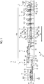
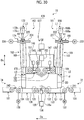
- Fig. 1 is a schematic configuration diagram illustrating the cardboard box production device of the present embodiment.
- Da represents the transport direction of a cardboard box
- Db represents the width direction of the cardboard box in a transport state (horizontal direction orthogonal to the transport direction Da)
- Dc represents the thickness direction of the cardboard box in the transport state (vertical direction orthogonal to the transport direction Da) .
- a cardboard box production device 10 includes a carton-forming machine 10A and a cardboard box dividing device (hereinafter, referred to as a dividing device) 71.
- the carton-forming machine 10A includes a sheet feeding section 11, a printing section 21, a slotter creaser section 31, a die cutting section 41, a folding section 51, and a counter-ejector section 61.
- the sheet feeding section 11, the printing section 21, the slotter creaser section 31, the die cutting section 41, the folding section 51, and the counter-ejector section 61 are disposed so as to form a linear shape along the transport direction Da in which a cardboard sheet S and a cardboard box B are transported, the dividing device 71 is disposed downstream of the counter-ejector section 61 in the transport direction Da, and a transport conveyor 81 is disposed between the counter-ejector section 61 and the dividing device 71.
- the carton-forming machine 10A produces the cardboard box B by processing a single box sheet of the cardboard sheet S.
- the cardboard box production device 10 produces the cardboard box B by processing a double box sheet SO of the cardboard sheet S.
- the carton-forming machine 10A produces a connected cardboard box body B0, in which two cardboard boxes B are connected along the transport direction Da, by processing the double box sheet S0, and the dividing device 71 produces the cardboard box B (B1 and B2) by cutting this connected cardboard box body B0 into two pieces.
- the sheet feeding section 11 ejects one cardboard sheet S (single box sheet or double box sheet) at a time and sends the cardboard sheet S to the printing section 21 at a constant speed.
- This sheet feeding section 11 has a table 12, a front pad 13, a supplying roller 14, a suction device 15, and a feed roll 16. Multiple cardboard sheets S can be stacked and placed on the table 12, and the table 12 is supported so as to be capable of ascending and descending.
- the front pad 13 is capable of positioning the front end position of the cardboard sheet S stacked on the table 12, and a gap through which one cardboard sheet S is capable of passing is ensured between the lower end portion of the front pad 13 and the table 12.
- a plurality of the supplying rollers 14 are disposed in the transport direction Da of the cardboard sheet S so as to correspond to the table 12 and, when the table 12 is lowered, the cardboard sheet S that is at the lowest position among the multiple stacked cardboard sheets S can be ejected forward.
- the suction device 15 suctions the stacked cardboard sheet S downward, that is, to the table 12 or supplying roller 14 side.
- the feed roll 16 is capable of supplying the cardboard sheet S ejected by the supplying roller 14 to the printing section 21.
- the printing section 21 performs multicolor printing (four-color printing in the present embodiment) on the surface of the cardboard sheet S.
- Four printing units 21A, 21B, 21C, and 21D are disposed in series in the printing section 21, and the printing section 21 is capable of performing printing on the surface of the cardboard sheet S by using four ink colors.
- Each of the printing units 21A, 21B, 21C, and 21D has substantially the same configuration and has a printing cylinder 22, an ink supply roll (anilox roll) 23, an ink chamber 24, and a receiving roll 25.
- the printing cylinder 22 has an outer peripheral portion to which a printing plate 26 is attached and is rotatably provided.
- the ink supply roll 23 is disposed so as to be in contact with the printing plate 26 in the vicinity of the printing cylinder 22 and is rotatably provided.
- the ink chamber 24, which stores ink, is provided in the vicinity of the ink supply roll 23.
- the receiving roll 25 transports the cardboard sheet S while imparting a predetermined printing pressure by sandwiching the cardboard sheet S between the printing cylinder 22 and the receiving roll 25 and is rotatably provided so as to face the lower part of the printing cylinder 22.
- a pair of upper and lower feed rolls (not illustrated) are provided in front of and behind each of the printing units 21A, 21B, 21C, and 21D.
- the slotter creaser section 31 performs creasing line processing, cutting, grooving, and glue tab processing on the cardboard sheet S.
- the slotter creaser section 31 has a first creasing line roll 32a, a second creasing line roll 32b, a slitter head 33, a first slotter head 34a, a second slotter head 34b, and a third slotter head 34c.
- the first creasing line roll 32a is formed in a circular shape, and a plurality of the first creasing line rolls 32a are disposed at predetermined intervals in the width direction Db of the cardboard sheet S.
- the second creasing line roll 32b is formed in a circular shape, and a plurality of the second creasing line rolls 32b are disposed at predetermined intervals in the width direction Db of the cardboard sheet S.
- the first creasing line roll 32a that is disposed on the lower side performs creasing line processing on the back surface (lower surface) of the cardboard sheet S
- the second creasing line roll 32b that is disposed on the lower side performs creasing line processing on the back surface (lower surface) of the cardboard sheet S similarly to the first creasing line roll 32a.
- Each of the creasing line rolls 32a and 32b is provided with receiving rolls 35a and 35b rotatable in synchronization at facing upper positions.
- the first slotter head 34a is formed in a circular shape, and a plurality of the first slotter heads 34a are disposed at predetermined intervals in the width direction Db of the cardboard sheet S.
- the first slotter head 34a performs grooving at a predetermined position in the transported cardboard sheet S and is capable of performing glue tab processing.
- the second slotter head 34b is formed in a circular shape, and a plurality of the second slotter heads 34b are disposed at predetermined intervals in the width direction Db of the cardboard sheet S.
- the second slotter head 34b performs grooving at a predetermined position in the transported cardboard sheet S and is capable of performing glue tab processing.
- Each of the slitter head 33 and the third slotter head 34c is formed in a circular shape, and a plurality of the slitter heads 33 and a plurality of the third slotter heads 34c are disposed at predetermined intervals in the width direction Db of the cardboard sheet S.
- the slitter head 33 is capable of cutting the end portion of the transported cardboard sheet S in the width direction Db.
- the third slotter head 34c performs grooving at a predetermined position in the transported cardboard sheet S and is capable of performing glue tab processing.
- Each of the slotter heads 34a, 34b, and 34c is provided with lower knives 36a, 36b, and 36c rotatable in synchronization at facing lower positions.
- the die cutting section 41 performs punching of a hand hole or the like on the cardboard sheet S.
- the die cutting section 41 has a pair of upper and lower feed pieces 42, an anvil cylinder 43, and a knife cylinder 44.
- the feed pieces 42 sandwich the cardboard sheet S from above and below, transport the cardboard sheet S, and are rotatably provided.
- Each of the anvil cylinder 43 and the knife cylinder 44 is formed in a circular shape, and the anvil cylinder 43 and the knife cylinder 44 can be rotated in synchronization by a drive device (not illustrated).
- a drive device not illustrated.
- an anvil is mounted onto the outer peripheral portion of the anvil cylinder 43, and a knife attachment base (punching knife) is attached at a predetermined position in the outer peripheral portion of the knife cylinder 44.
- the folding section 51 forms the flat cardboard box B by folding the cardboard sheet S while moving the cardboard sheet S in the transport direction Da and bonding both end portions in the width direction Db.
- the folding section 51 has an upper transport belt 52, lower transport belts 53 and 54, and a forming device 55.
- the upper transport belt 52 and the lower transport belts 53 and 54 sandwich the cardboard sheet S and the cardboard box B from above and below and transport the cardboard sheet S and the cardboard box B.
- the forming device 55 has a pair of left and right forming belts and folds each end portion of the cardboard sheet S in the width direction Db while bending the end portion downward with this forming belt.
- the folding section 51 is provided with a gluing device 56.
- This gluing device 56 has a glue gun and is capable of performing glue application at a predetermined position in the cardboard sheet S by discharging glue at a predetermined timing.
- the counter-ejector section 61 stacks the cardboard box B while counting the cardboard box B, sorts the cardboard box B into a predetermined number of batches, and then discharges the batches.
- the counter-ejector section 61 has a hopper device 62.
- This hopper device 62 has an elevator 63 on which the cardboard box B is stacked, the elevator 63 can be lifted and lowered, and this elevator 63 is provided with a front stopper plate (not illustrated) and a squaring plate (not illustrated) as folding accuracy improvement.
- an unloading conveyor 64 is provided below the hopper device 62.
- the dividing device 71 which is movable to a use position and a retreat position, is used when the carton-forming machine 10A has produced the connected cardboard box body B0, in which the two cardboard boxes B are connected along the transport direction Da, by processing the double box sheet S0.
- the dividing device 71 moves to the retreat position when the carton-forming machine 10A produces the cardboard box B by processing the single box sheet.
- the dividing device 71 moves to the use position when the carton-forming machine 10A produces the connected cardboard box body B0 by processing the double box sheet S0.
- the dividing device 71 produces the cardboard box B (B1 and B2) by cutting the connected cardboard box body B0 into two pieces.
- the dividing device 71 has a loading device 72, a cutting device 73, and an unloading device 74.
- the loading device 72 receives a plurality of the connected cardboard box bodies B0 transported by the transport conveyor 81 from the counter-ejector section 61 and supplies the connected cardboard box bodies B0 to the cutting device 73.
- the cutting device 73 produces the cardboard boxes B1 and B2 by dividing the connected cardboard box body B0 into one front part and one rear part.
- the unloading device 74 receives the cardboard boxes B1 and B2 divided into two from the cutting device 73 and unloads the cardboard boxes B1 and B2.
- Fig. 21 is a plan view illustrating the double box sheet that is yet to be folded.
- the double box sheet SO is formed by glue application of a corrugated medium between a bottom liner and a top liner and cut in advance into a size that allows the two cardboard boxes B to be produced.
- the double box sheet SO has a size obtained by single box sheets S1 and S2 being connected.
- the double box sheet SO has four folding lines 301, 302, 303, and 304 formed in a previous step.
- the folding lines 301, 302, 303, and 304 are for folding a flap when the cardboard box B produced by the carton-forming machine 10A is assembled later.
- the double box sheet SO on which each of the folding lines 301, 302, 303, and 304 is formed is stacked on the table 12 in the sheet feeding section 11.
- the double box sheet SO stacked on the table 12 is positioned by the front pad 13 and ejected by the plurality of supplying rollers 14 by the table 12 being lowered. Then, the double box sheet SO is supplied to the printing section 21 at a predetermined constant speed by a pair of the feed rolls 16.
- ink is supplied from the ink chamber 24 to the surface of the ink supply roll 23, and the ink on the surface of the ink supply roll 23 is transferred to the printing plate 26 when the printing cylinder 22 and the ink supply roll 23 rotate.
- the double box sheet SO is subsequently transported between the printing cylinder 22 and the receiving roll 25, the double box sheet SO is sandwiched by the printing plate 26 and the receiving roll 25, and printing is performed on the surface by the printing pressure being imparted here.
- the printed double box sheet SO is transported to the slotter creaser section 31 by the feed roll.
- creasing lines 312, 313, 314, and 315 are formed on the back surface (top liner) side as illustrated in Fig. 21 .
- the creasing lines 312, 313, 314, and 315 are formed again on the back surface (top liner) side of the cardboard sheet S similarly to the first creasing line roll 32a.
- glue tabs 326a and 326b are formed by end portions 325a, 325b, 325c, and 325d being cut at the position of the creasing line 315. Subsequently, the double box sheet SO is transported to the die cutting section 41 as illustrated in Fig. 1 .
- a hand hole (not illustrated) is formed when the double box sheet SO passes between the anvil cylinder 43 and the knife cylinder 44.
- the hand hole processing is appropriately performed in accordance with the type of the double box sheet S0, and the knife attachment base (punching knife) for performing the hand hole processing is removed from the knife cylinder 44 when the hand hole is unnecessary.
- the hand hole processing of the double box sheet SO by the die cutting section 41 is omitted, and the double box sheet SO passes between the anvil cylinder 43 and the knife cylinder 44 that rotate.
- the gluing device 56 applies glue to the glue tabs 326a and 326b as illustrated in Fig. 21 while the double box sheet SO is moved in the transport direction Da by the upper transport belt 52 and the lower transport belts 53 and 54, and then the double box sheet SO is folded downward from the creasing lines 312 and 314 by the forming device 55.
- this folding is advanced to nearly 180 degrees, the folding force becomes stronger, the glue tabs 326a and 326b and the end portion of the double box sheet SO are pressed and adhere to each other, both end portions of the double box sheet SO are bonded, and the connected cardboard box body B0 is formed. Then, this connected cardboard box body B0 is transported to the counter-ejector section 61 as illustrated in Fig. 1 .
- the connected cardboard box body B0 is sent to the hopper device 62, the leading edge portion of the connected cardboard box body B0 in the transport direction Da hits the front stopper plate, and the connected cardboard box body B0 is stacked onto the elevator 63 in a state where the connected cardboard box body B0 is shaped by the squaring plate. Then, when a predetermined number of the cardboard boxes B are stacked on the elevator 63, this elevator 63 descends and a predetermined number of the connected cardboard box bodies B0 are discharged as one batch by the unloading conveyor 64. Then, the predetermined number of stacked connected cardboard box bodies B0 are sent to the dividing device 71 by the transport conveyor 81.
- the dividing device 71 the plurality of connected cardboard box bodies B0 transported by the transport conveyor 81 from the counter-ejector section 61 are supplied to the loading device 72.
- the loading device 72 receives the plurality of stacked connected cardboard box bodies B0 and supplies the stacked connected cardboard box bodies B0 to the cutting device 73.
- the cutting device 73 produces the cardboard boxes B1 and B2 by dividing the plurality of connected cardboard box bodies B0 into one front part and one rear part by cutting the plurality of connected cardboard box bodies B0 at the position of a two-dot chain line 331 (see Fig. 21 ) along the width direction Db.
- the unloading device 74 receives and unloads the cardboard boxes B1 and B2 divided into two by the cutting device 73.
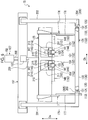
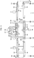
- Fig. 2 is a schematic configuration diagram illustrating the cardboard box dividing device of the present embodiment
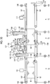
- Fig. 3 is a plan view illustrating an upper conveyor in the cardboard box dividing device
- Fig. 4 is a plan view illustrating a lower conveyor in the cardboard box dividing device.
- the dividing device 71 has the loading device 72, the cutting device 73, and the unloading device 74.
- the loading device 72, the cutting device 73, and the unloading device 74 are disposed along the transport direction Da of the connected cardboard box body B0 or the cardboard box B (B1 and B2).
- the loading device 72 supplies the plurality of stacked connected cardboard box bodies B0 to the cutting device 73 and has a loading lower conveyor 101 and a loading upper conveyor 102.
- the loading lower conveyor 101 and the loading upper conveyor 102 are disposed so as to face each other at a predetermined interval in the thickness direction Dc of the cardboard sheet S.
- the loading lower conveyor 101 and the loading upper conveyor 102 have substantially the same length in the transport direction Da, the length of the loading upper conveyor 102 in the width direction Db is shorter than the length of the loading lower conveyor 101 in the width direction Db.
- the loading lower conveyor 101 is configured by an endless transport belt 105 stretching between a driving roller 103 and a driven roller 104.
- the loading upper conveyor 102 is configured by an endless transport belt 108 stretching between a driving roller 106 and a driven roller 107. It should be noted that the slack of the transport belts 105 and 108 is prevented by a plurality of rollers (not illustrated) being respectively disposed between the driving rollers 103 and 106 and the driven rollers 104 and 107 in the loading lower conveyor 101 and the loading upper conveyor 102.
- the loading lower conveyor 101 is provided with a drive motor 109 capable of driving and rotating the driving roller 103.
- the loading upper conveyor 102 is provided with a drive motor 110 capable of driving and rotating the driving roller 106.
- the loading upper conveyor 102 is supported such that the loading upper conveyor 102 can be moved up and down by a loading upper conveyor moving device 111.
- the loading device 72 has a left side portion alignment device 112 and a right side portion alignment device 113.
- the left side portion alignment device 112 and the right side portion alignment device 113 are disposed so as to face each other in the width direction Db.
- Alignment plates 114 and 115, which face each other in the width direction Db, and drive cylinders 116 and 117, which respectively move the alignment plates 114 and 115 along the width direction Db, constitute the left side portion alignment device 112 and the right side portion alignment device 113, respectively. It should be noted that the positions of the left side portion alignment device 112 and the right side portion alignment device 113 can be adjusted in the width direction Db in accordance with the width dimension of the connected cardboard box body B0 to be processed.
- the loading device 72 has an opening-closing door 118.
- the opening-closing door 118 has a plate shape disposed along the width direction Db and the thickness direction Dc upstream of the loading lower conveyor 101 in the transport direction Da.
- the opening-closing door 118 can be moved along the thickness direction Dc by a drive cylinder 119 and is movable to a closed position positioned above the loading lower conveyor 101 and an open position positioned below the loading lower conveyor 101.
- the cutting device 73 cuts a connected cardboard box laminate in which a plurality of the connected cardboard box bodies B0 are stacked in the thickness direction Dc along the width direction Db and divides the laminate into the two cardboard boxes B1 and B2.
- the cutting device 73 has an inlet side lower conveyor 121 and an outlet side lower conveyor 122 as lower conveyors, an inlet side upper conveyor 123 and an outlet side upper conveyor 124 as upper conveyors, a pressing device 125, a cutting knife 126, a lifting/lowering device 127, and a positioning device 128.
- the inlet side lower conveyor 121 and the outlet side lower conveyor 122 stack and transport the plurality of connected cardboard box bodies B0, the inlet side lower conveyor 121 and the outlet side lower conveyor 122 have the same length as the loading lower conveyor 101 in the width direction Db, and the length of each of the inlet side lower conveyor 121 and the outlet side lower conveyor 122 is approximately half of the length of the loading lower conveyor 101 in the transport direction Da.
- the inlet side lower conveyor 121 and the outlet side lower conveyor 122 have the same length in the width direction Db and have the same length in the transport direction Da.
- the inlet side lower conveyor 121 and the outlet side lower conveyor 122 are disposed with a predetermined gap in the transport direction Da.
- the inlet side lower conveyor 121 is configured by an endless transport belt 133 stretching between a driving roller 131 and a driven roller 132.
- the outlet side lower conveyor 122 is configured by an endless transport belt 136 stretching between a driving roller 134 and a driven roller 135. It should be noted that the slack of the transport belts 133 and 136 is prevented by a plurality of rollers (not illustrated) being respectively disposed between the driving rollers 131 and 134 and the driven rollers 132 and 135 in the inlet side lower conveyor 121 and the outlet side lower conveyor 122.
- the inlet side lower conveyor 121 is provided with a drive motor 137 capable of driving and rotating the driving roller 131.
- the outlet side lower conveyor 122 is provided with a drive motor 138 capable of driving and rotating the driving roller 134.
- the inlet side upper conveyor 123 and the outlet side upper conveyor 124 support and transport the upper portions of the plurality of connected cardboard box bodies B0 stacked on the inlet side lower conveyor 121 and the outlet side lower conveyor 122, a plurality of (two in the present embodiment) conveyors constitute the inlet side upper conveyor 123 and the outlet side upper conveyor 124, and the plurality of conveyors are shorter in length than the inlet side lower conveyor 121 and the outlet side lower conveyor 122 in the width direction Db and the transport direction Da.
- the inlet side upper conveyor 123 and the outlet side upper conveyor 124 are disposed with a predetermined gap in the transport direction Da.
- the inlet side upper conveyor 123 is disposed so as to face the inlet side lower conveyor 121 from above and is configured by an endless transport belt 141 stretching between a driving roller 139 and a driven roller 140.
- the outlet side upper conveyor 124 is disposed so as to face the outlet side lower conveyor 122 from above and is configured by an endless transport belt 144 stretching between a driving roller 142 and a driven roller 143.
- two conveyors are disposed side by side at a predetermined interval in the width direction Db.
- the inlet side upper conveyor 123 and the outlet side upper conveyor 124 that are on the left side with respect to the transport direction Da are provided with a drive motor 145 capable of driving and rotating each of the driving rollers 139 and 142
- the inlet side upper conveyor 123 and the outlet side upper conveyor 124 that are on the right side with respect to the transport direction Da are provided with a drive motor 146 capable of driving and rotating each of the driving rollers 139 and 142.
- the inlet side upper conveyor 123 and the outlet side upper conveyor 124 are supported such that the inlet side upper conveyor 123 and the outlet side upper conveyor 124 can be moved up and down by an inlet side upper conveyor moving device 147 and an outlet side upper conveyor moving device 148.
- the pressing device 125 presses, from above, the plurality of connected cardboard box bodies B0 stacked on the inlet side lower conveyor 121 and the outlet side lower conveyor 122.
- the pressing device 125 has width direction pressing members 149 and 150 that are along the width direction Db above the inlet side lower conveyor 121 and the outlet side lower conveyor 122 and a plurality of transport direction pressing members 151 and 152 that are along the transport direction Da.
- the width direction pressing member 149 is disposed in the downstream portion of the inlet side upper conveyor 123 and is configured by the plurality of transport direction pressing members 151 extending from the width direction pressing member 149 to the upstream side in the transport direction Da.
- the width direction pressing member 150 is disposed in the upstream portion of the outlet side upper conveyor 124 and is configured by the plurality of transport direction pressing members 152 extending from the width direction pressing member 150 to the downstream side in the transport direction Da.
- the pressing device 125 is supported such that the pressing device 125 can be moved up and down by a pressing drive device 153.
- the cutting knife 126 is disposed along the width direction Db between the inlet side lower conveyor 121 and the outlet side lower conveyor 122, and a knife portion is formed along the upper portion of the cutting knife 126.
- the cutting knife 126 which has an endless shape, is supported by being wound around a driving pulley 154 and a driven pulley 155 disposed on both sides of the inlet side lower conveyor 121 in the width direction Db.
- a cutting knife drive device 156 is capable of driving and rotating the driving pulley 154, and the cutting knife drive device 156 is capable of moving the cutting knife 126 in the width direction Db between the inlet side lower conveyor 121 and the outlet side lower conveyor 122 by the driving pulley 154 rotating. It should be noted that the cutting knife 126 has a cutting position between the inlet side lower conveyor 121 and the outlet side lower conveyor 122 and simply moves between the inlet side lower conveyor 121 and the loading lower conveyor 101.
- the lifting/lowering device 127 relatively moves the cutting knife 126 and the plurality of connected cardboard box bodies B0 on the inlet side lower conveyor 121 and the outlet side lower conveyor 122 along the up-down direction.
- the lifting/lowering device 127 causes the cutting knife 126 to be immovable in the up-down direction and is capable of lifting and lowering the inlet side lower conveyor 121, the outlet side lower conveyor 122, the inlet side upper conveyor 123, the outlet side upper conveyor 124, and the pressing device 125 along the up-down direction.
- the inlet side lower conveyor 121, the outlet side lower conveyor 122, the inlet side upper conveyor 123, the outlet side upper conveyor 124, and the pressing device 125 are supported by a lifting/lowering base 157.
- a lifting/lowering drive device 158 is capable of lifting and lowering the lifting/lowering base 157 along the up-down direction, and the inlet side lower conveyor 121, the outlet side lower conveyor 122, the inlet side upper conveyor 123, the outlet side upper conveyor 124, and the pressing device 125 are lifted and lowered by the lifting/lowering base 157 being lifted and lowered.
- the lifting/lowering base 157 being lowered, the plurality of connected cardboard box bodies B0 supported by the inlet side lower conveyor 121, the outlet side lower conveyor 122, the inlet side upper conveyor 123, the outlet side upper conveyor 124, and the pressing device 125 are lowered and the plurality of connected cardboard box bodies B0 are cut by the cutting knife 126.
- the positioning device 128 positions, in the transport direction Da, the plurality of connected cardboard box bodies B0 supplied on the inlet side lower conveyor 121 and the outlet side lower conveyor 122.
- the positioning device 128 has two upstream side positioning members 161 and two downstream side positioning members 162.
- the upstream side positioning member 161 is movable along the transport direction Da and the thickness direction Dc of the connected cardboard box body B0 in the upstream portion of the inlet side lower conveyor 121.
- the downstream side positioning member 162 is movable along the transport direction Da and the thickness direction Dc of the connected cardboard box body B0 in the downstream portion of the outlet side lower conveyor 122.
- the upstream side positioning member 161 and the downstream side positioning member 162 can be independently moved by a positioning drive device.
- the upstream side positioning member 161 forms a telescopic structure in which a supporting cylinder 163, an outer cylinder 164, and an inner cylinder 165 are mutually fitted.
- a first drive device 166 is capable of lifting and lowering the outer cylinder 164 along the thickness direction Dc with respect to the fixed supporting cylinder 163, and a second drive device 167 is capable of lifting and lowering the inner cylinder 165 along the thickness direction Dc with respect to the outer cylinder 164.
- a third drive device 168 is capable of moving the supporting cylinder 163 along with the outer cylinder 164 and the inner cylinder 165 along the transport direction Da.
- the downstream side positioning member 162 forms a telescopic structure in which a supporting cylinder 169, an outer cylinder 170, and an inner cylinder 171 are mutually fitted.
- a first drive device 172 is capable of lifting and lowering the outer cylinder 170 along the thickness direction Dc with respect to the fixed supporting cylinder 169
- a second drive device 173 is capable of lifting and lowering the inner cylinder 171 along the thickness direction Dc with respect to the outer cylinder 170.
- a third drive device 174 is capable of moving the supporting cylinder 169 along with the outer cylinder 170 and the inner cylinder 171 along the transport direction Da.
- the upstream side positioning member 161 forms the telescopic structure in which the supporting cylinder 163, the outer cylinder 164, and the inner cylinder 165 are mutually fitted, and thus the width of the outer cylinder 164 in the transport direction Da is smaller than the width of the supporting cylinder 163 in the transport direction Da and the width of the inner cylinder 165 in the transport direction Da is smaller than the width of the outer cylinder 164 in the transport direction Da.
- the downstream side positioning member 162 forms the telescopic structure in which the supporting cylinder 169, the outer cylinder 170, and the inner cylinder 171 are mutually fitted, and thus the width of the outer cylinder 170 in the transport direction Da is smaller than the width of the supporting cylinder 169 in the transport direction Da and the width of the inner cylinder 171 in the transport direction Da is smaller than the width of the outer cylinder 170 in the transport direction Da.
- the drive devices 166, 167, 168, 172, 173, and 174 constitute the positioning drive device.
- the cutting device 73 has a left side portion alignment device 175 and a right side portion alignment device 176.
- the left side portion alignment device 175 and the right side portion alignment device 176 are disposed so as to face each other in the width direction Db.
- the left side portion alignment device 175 is disposed beside the inlet side lower conveyor 121 and the outlet side lower conveyor 122, and the alignment plate 177 extends to below the inlet side lower conveyor 121 and the outlet side lower conveyor 122.
- the right side portion alignment device 176 is disposed above the inlet side lower conveyor 121 and the outlet side lower conveyor 122, and the alignment plate 178 extends to the upper surfaces of the inlet side lower conveyor 121 and the outlet side lower conveyor 122. Accordingly, in the left side portion alignment device 175, no gap is generated between the lower end portion of the alignment plate 177 and the respective upper surfaces of the lower conveyors 121 and 122, and thus it is possible to appropriately perform paper alignment in the width direction Db by aligning the plurality of connected cardboard box bodies B0 stacked on the lower conveyors 121 and 122 with the alignment plate 177 when the alignment plates 177 and 178 have moved so as to approach each other. In addition, the position of the right side portion alignment device 176 can be adjusted in the width direction Db in accordance with the width dimension of the connected cardboard box body B0 to be processed.
- the unloading device 74 receives the plurality of stacked cardboard boxes B1 and B2 cut by the cutting device 73, unloads the cardboard boxes B1 and B2 to the outside, and has an unloading lower conveyor 181 and an unloading upper conveyor 182.
- the unloading lower conveyor 181 and the unloading upper conveyor 182 are disposed so as to face each other at a predetermined interval in the thickness direction Dc of the cardboard sheet S.
- the unloading lower conveyor 181 and the unloading upper conveyor 182 have substantially the same length in the transport direction Da, the length of the unloading upper conveyor 182 in the width direction Db is shorter than the length of the unloading lower conveyor 181 in the width direction Db.
- the unloading lower conveyor 181 is configured by an endless transport belt 185 stretching between a driving roller 183 and a driven roller 184.
- the unloading upper conveyor 182 is configured by an endless transport belt 188 stretching between a driving roller 186 and a driven roller 187. It should be noted that the slack of the transport belts 185 and 188 is prevented by a plurality of rollers (not illustrated) being respectively disposed between the driving rollers 183 and 186 and the driven rollers 184 and 187 in the unloading lower conveyor 181 and the unloading upper conveyor 182.
- the unloading lower conveyor 181 is provided with a drive motor 189 capable of driving and rotating the driving roller 183.
- the unloading upper conveyor 182 is provided with a drive motor 190 capable of driving and rotating the driving roller 186.
- the unloading upper conveyor 182 is supported such that the unloading upper conveyor 182 can be moved up and down by an unloading upper conveyor moving device 191.
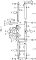
- Fig. 5 is a schematic front view illustrating the cardboard box cutting device
- Fig. 6 is a schematic side view illustrating the cardboard box cutting device.
- the lifting/lowering base 157 has a beam shape along the horizontal direction, and frame bodies 203, 204, 205, and 206 in the inlet side lower conveyor 121 and the outlet side lower conveyor 122 are connected via a pair of left and right connecting members 201 and 202.
- the lifting/lowering drive device 158 is provided in a device frame 207, and the leading edge portion of a drive rod 208 is connected to the lifting/lowering base 157.
- the lifting/lowering base 157 is provided with the pressing drive device 153, and the leading edge portion of a drive rod 209 is connected to a support frame 210 of the pressing device 125.
- the support frame 210 is disposed along the width direction Db, two attachment frames 211 are fixed on the upstream side in the transport direction Da, and two attachment frames 212 are fixed on the downstream side.
- the width direction pressing member 149 and the transport direction pressing member 151 are fixed to the lower surface of the attachment frame 211, and the width direction pressing member 150 and the transport direction pressing member 152 are fixed to the lower surface of the attachment frame 212.
- the left side portion alignment device 175 and the right side portion alignment device 176 are supported by the support frame 210 and each of the alignment plates 177 and 178 hangs downward.
- the alignment plate 178 is movable in the width direction Db.
- the inlet side upper conveyor 123 and the outlet side upper conveyor 124 are disposed in the pressing members 149, 150, 151, and 152.
- the inlet side upper conveyor 123 and the outlet side upper conveyor 124 are disposed in the attachment frames 211 and 212 supporting the pressing members 149, 150, 151, and 152.
- the attachment frames 211 and 212 are provided with space sections 213 and 214, which open downward.
- the inlet side upper conveyor moving device 147 is fixed to the space section 213, and the inlet side upper conveyor 123 is connected to the leading edge portion of a drive rod 215.
- the outlet side upper conveyor moving device 148 is fixed to the space section 214, and the outlet side upper conveyor 124 is connected to the leading edge portion of a drive rod 216.
- the drive rod 208 expands and contracts, the lifting/lowering base 157 can be lifted and lowered, and the inlet side lower conveyor 121, the outlet side lower conveyor 122, the inlet side upper conveyor 123, the outlet side upper conveyor 124, and the pressing device 125 supported by the lifting/lowering base 157 can be lifted and lowered.
- the pressing drive device 153 the drive rod 209 expands and contracts and the pressing device 125, the inlet side upper conveyor 123, and the outlet side upper conveyor 124 can be lifted and lowered with respect to the lifting/lowering base 157.
- the conveyor moving devices 147 and 148 are driven, the drive rods 215 and 216 expand and contract and the inlet side upper conveyor 123 and the outlet side upper conveyor 124 can be lifted and lowered with respect to the pressing device 125.
- the control device 231 is capable of performing drive control on the loading upper conveyor moving device 111, the drive cylinders 116, 117, and 119, and the drive motors 109 and 110 of the loading device 72.
- the control device 231 is capable of performing drive control on the conveyor moving devices 147 and 148, the pressing drive device 153, the lifting/lowering drive device 158, the drive devices 166, 167, 168, 172, 173, and 174, and the drive motors 137, 138, 145, and 146 of the cutting device 73.
- the control device 231 is capable of performing drive control on the unloading upper conveyor moving device 191 and the drive motors 189 and 190 of the unloading device 74.
- Fig. 7 is a schematic front view illustrating the cardboard box positioning device
- Figs. 8 and 9 are schematic diagrams illustrating the operation of the cardboard box positioning device.
- the first drive device 166 is capable of lifting and lowering the outer cylinder 164 with respect to the supporting cylinder 163
- the second drive device 167 is capable of lifting and lowering the inner cylinder 165 with respect to the outer cylinder 164
- the third drive device 168 is capable of moving the supporting cylinder 163, the outer cylinder 164, and the inner cylinder 165 along the transport direction Da.
- an air cylinder or the like constitutes the first drive device 166 and the second drive device 167
- the third drive device 168 is constituted by a screw shaft 221, a moving body 222 fixed to the supporting cylinder 163 and screwed with the screw shaft 221, and a motor 223 driving and rotating the screw shaft 221.
- the first drive device 172 is capable of lifting and lowering the outer cylinder 170 with respect to the supporting cylinder 169
- the second drive device 173 is capable of lifting and lowering the inner cylinder 171 with respect to the outer cylinder 170
- the third drive device 174 is capable of moving the supporting cylinder 169, the outer cylinder 170, and the inner cylinder 171 in the transport direction Da.
- an air cylinder or the like constitutes the first drive device 172 and the second drive device 173
- the third drive device 174 is constituted by a screw shaft 224, a moving body 225 fixed to the supporting cylinder 169 and screwed with the screw shaft 224, and a motor 226 driving and rotating the screw shaft 224.
- the positioning drive device of the present invention is each of the drive devices 166, 167, 168, 172, 173, and 174 and is capable of independently moving the upstream side positioning member 161 and the downstream side positioning member 162.
- control device 231 operates the outer cylinders 164 and 170 and the inner cylinders 165 and 171 along the thickness direction Dc with respect to the supporting cylinders 163 and 169 by performing drive control on the first drive devices 166 and 172 and the second drive devices 167 and 173 as the lifting/lowering base 157 is lifted and lowered.
- the control device 231 moves the downstream side positioning member 162 by a predetermined distance to the upstream side in the transport direction Da by performing drive control on the third drive device 174 after the cutting knife 126 cuts the plurality of connected cardboard box bodies B0 into front and rear parts and the lifting/lowering base 157, the upstream side positioning member 161, and the downstream side positioning member 162 are lifted.
- control device 231 moves the downstream side positioning member 162 by the predetermined distance to the upstream side in the transport direction Da by performing drive control on the third drive device 174 during the passage of the cut cardboard boxes B1 and B2 below the downstream side positioning member 162 by the inlet side lower conveyor 121 and the outlet side lower conveyor 122 when the upstream side positioning member 161 and the downstream side positioning member 162 are at a rise position.
- control device 231 lowers the outer cylinder 170 and the inner cylinder 171 by performing drive control on the first drive device 172 and moves the downstream side positioning member 162 by a predetermined distance to the downstream side in the transport direction Da by performing drive control on the third drive device 174 after the passage of the cut cardboard boxes B1 and B2 below the downstream side positioning member 162 by the inlet side lower conveyor 121 and the outlet side lower conveyor 122.
- the downstream side positioning member 162 is provided with an arrival detection sensor 232, which detects the arrival of the connected cardboard box body B0 (leading edge in the transport direction Da), on the supporting cylinder 169, and is provided with a passage detection sensor 233, which detects the passage of the cardboard boxes B1 and B2.
- the arrival detection sensor 232 and the passage detection sensor 233 output detection results to the control device 231.
- the control device 231 stops operating the inlet side lower conveyor 121, the outlet side lower conveyor 122, the inlet side upper conveyor 123, and the outlet side upper conveyor 124 when the arrival detection sensor 232 detects the arrival of the connected cardboard box body B0.
- the control device 231 starts lowering the outer cylinder 170 and the inner cylinder 171 in the downstream side positioning member 162 when the passage detection sensor 233 detects the passage of the cardboard boxes B1 and B2 below the downstream side positioning member 162.
- the cut cardboard boxes B1 and B2 are lifted together with the inlet side lower conveyor 121 and the outlet side lower conveyor 122 when the connected cardboard box body B0 is cut by the cutting knife 126 by the connected cardboard box body B0 supported by the inlet side lower conveyor 121 and the outlet side lower conveyor 122 being lowered.
- the upstream side positioning member 161 and the downstream side positioning member 162 are lifted and lowered so as to follow the lifting and lowering of the inlet side lower conveyor 121 and the outlet side lower conveyor 122 as the inlet side lower conveyor 121 and the outlet side lower conveyor 122 are lifted and lowered.
- the upstream side positioning member 161 and the downstream side positioning member 162 are lifted together with the cardboard boxes B1 and B2, the upstream side positioning member 161 is moved to the upstream side in the transport direction Da by a predetermined distance as indicated by a two-dot chain line in Fig. 7 .
- the downstream side positioning member 162 indicated by a two-dot chain line in Fig. 8 is moved by a predetermined distance (such as the position indicated by a solid line in Fig. 8 ) to the upstream side in the transport direction Da when the passage detection sensor 233 detects the passage of the cardboard boxes B1 and B2 below the downstream side positioning member 162 after the upstream side positioning member 161 and the downstream side positioning member 162 are lifted as illustrated in Fig. 8 .
- the outer cylinder 170 is lowered with the inner cylinder 171 held in the outer cylinder 170 and the downstream side positioning member 162 is moved by a predetermined distance (such as the position indicated by a two-dot chain line in Fig. 9 ) to the downstream side in the transport direction Da as illustrated in Fig. 9 when the passage detection sensor 233 detects the completion of the passage of the cardboard boxes B1 and B2 below the downstream side positioning member 162.
- Fig. 10 is a time chart illustrating operation in the cardboard box dividing device
- Fig. 11 is a schematic diagram illustrating the loading state of the connected cardboard box body
- Fig. 12 is a schematic diagram illustrating the retreat state of the upper conveyor
- Fig. 13 is a schematic diagram illustrating the state of positioning by the positioning member
- Fig. 14 is a schematic diagram illustrating the state of pressing by the pressing device
- Fig. 15 is a schematic diagram illustrating the state of cutting by the processing of the connected cardboard box body
- Fig. 16 is a schematic diagram illustrating the lifting state of the cardboard box
- Fig. 10 is a time chart illustrating operation in the cardboard box dividing device
- Fig. 11 is a schematic diagram illustrating the loading state of the connected cardboard box body
- Fig. 12 is a schematic diagram illustrating the retreat state of the upper conveyor
- Fig. 13 is a schematic diagram illustrating the state of positioning by the positioning member
- Fig. 14 is a schematic diagram illustrating the state of pressing by the pressing device
- FIG. 17 is a schematic diagram illustrating the support state of the upper conveyor
- Fig. 18 is a schematic diagram illustrating the movement state of the downstream side positioning member
- Fig. 19 is a schematic diagram illustrating the unloading state of the cardboard box
- Fig. 20 is a schematic diagram illustrating the unloading state of the cardboard box and the loading state of the connected cardboard box body.
- the cut cardboard boxes B1 and B2 are unloaded until time t5.
- the unloading lower conveyor 181 and the unloading upper conveyor 182 in the unloading device 74 stop the drive rotation of the respective drive motors 189 and 190 at time t5 and completely stop at time t6.
- the arrival detection sensor 232 is turned OFF from time t2 to t3, and the passage detection sensor 233 is turned OFF from time t3 to t4.
- the loading lower conveyor 101 and the loading upper conveyor 102 in the loading device 72 start operating by the drive rotation of the respective drive motors 109 and 110.
- the inlet side lower conveyor 121, the outlet side lower conveyor 122, the inlet side upper conveyor 123, and the outlet side upper conveyor 124 in the cutting device 73 are in operation by the drive rotation of the respective drive motors 137, 138, 145, and 146. Accordingly, the connected cardboard box body B0 is loaded by the loading device 72 and supplied to the cutting device 73.
- the first drive device 172 is driven and lowering is performed with the inner cylinder 171 held in the outer cylinder 170 of the downstream side positioning member 162 from time t4 to t5, and the third drive device 174 is driven, the downstream side positioning member 162 moves to the downstream side in the transport direction Da, and the downstream side positioning member 162 stops at a paper alignment position from time t4 to t6.
- the arrival detection sensor 232 detects the leading edge of the connected cardboard box body B0 and is turned ON from time t6 to t7. Then, the loading lower conveyor 101 and the loading upper conveyor 102 in the loading device 72 stop operating from time t7 to t8. In addition, the inlet side lower conveyor 121, the outlet side lower conveyor 122, the inlet side upper conveyor 123, and the outlet side upper conveyor 124 in the cutting device 73 stop operating from time t8 to t9.
- the left side portion alignment device 175 and the right side portion alignment device 176 operate (paper alignment execution) from time t11 to t12 and perform paper alignment in the width direction Db on the plurality of connected cardboard box bodies B0 stacked on the inlet side lower conveyor 121 and the outlet side lower conveyor 122.
- the outer cylinder 164 moves to the downstream side in the transport direction Da from time t13 to t14 and the upstream side positioning member 161 performs paper alignment in the transport direction Da on the plurality of connected cardboard box bodies B0 stacked on the inlet side lower conveyor 121 and the outlet side lower conveyor 122 together with the outer cylinder 170 of the downstream side positioning member 162.
- the upstream side positioning member 161 and the downstream side positioning member 162 exert a descending-direction stress on each of the inner cylinders 165 and 171 from time t16 to t17.
- the pressing device 125 performs pressing support on the plurality of connected cardboard box bodies B0 stacked on the inlet side lower conveyor 121 and the outlet side lower conveyor 122 by lowering the width direction pressing members 149 and 150 and the transport direction pressing members 151 and 152 from time t15 to t16.
- the plurality of connected cardboard box bodies B0 are lowered by the lifting/lowering device 127 operating from time t16 to t17 as illustrated in Figs. 10 and 15 when the plurality of connected cardboard box bodies B0 stacked on the inlet side lower conveyor 121 and the outlet side lower conveyor 122 are supported by the left side portion alignment device 175, the right side portion alignment device 176, the upstream side positioning member 161, the downstream side positioning member 162, the width direction pressing members 149 and 150, and the transport direction pressing members 151 and 152.
- the cutting knife 126 relatively ascends, cuts the plurality of connected cardboard box bodies B0 along the width direction Db, and turns the plurality of connected cardboard box bodies B0 into the plurality of cardboard boxes B1 and B2.
- the respective inner cylinders 165 and 171 of the upstream side positioning member 161 and the downstream side positioning member 162 which are respectively narrower in width than the outer cylinders 164 and 170, descend, and thus a gap is ensured between the plurality of connected cardboard box bodies B0.
- the plurality of cardboard boxes B1 are slightly movable in the range of the gap toward the downstream side in the transport direction Da and the plurality of cardboard boxes B2 are slightly movable in the range of the gap toward the upstream side in the transport direction Da.
- the lifting/lowering device 127 operates from time t17 to t20 and the plurality of cardboard boxes B1 and B2 are lifted as illustrated in Figs. 10 and 16 .
- the left side portion alignment device 175 and the right side portion alignment device 176 operate (paper alignment release) from time t17 to t18 and move to the standby position separated from the cardboard boxes B1 and B2.
- the upstream side positioning member 161 and the downstream side positioning member 162 ascend from time t17 to t20.
- the upstream side positioning member 161 moves to the upstream side in the transport direction Da from time t17 to t21.
- the pressing device 125 lifts the width direction pressing members 149 and 150 and the transport direction pressing members 151 and 152 from time t18 to t21 as illustrated in Figs. 10 and 17 , and the pressing support of the plurality of cardboard boxes B1 and B2 stacked on the inlet side lower conveyor 121 and the outlet side lower conveyor 122 is released as a result. Meanwhile, the inlet side upper conveyor 123 and the outlet side upper conveyor 124 descend from time t18 to t19 and support the upper portions of the cardboard boxes B1 and B2. In addition, as illustrated in Figs.
- the unloading lower conveyor 181 and the unloading upper conveyor 182 in the unloading device 74, the inlet side lower conveyor 121, the outlet side lower conveyor 122, the inlet side upper conveyor 123, and the outlet side upper conveyor 124 start operating at time t21.
- the downstream side positioning member 162 moves to the standby position on the upstream side in the transport direction Da from time t22 to t23.
- the passage detection sensor 233 detects the leading edge of the cardboard box B1 with unloading started and is turned ON from time t21 to t22.
- the plurality of cardboard boxes B1 and B2 are transferred from the cutting device 73 to the unloading device 74 as illustrated in Figs. 10 and 19 , and the plurality of cardboard boxes B1 and B2 are unloaded by the unloading device 74 as illustrated in Figs. 10 and 20 . Subsequently, the downstream side positioning member 162 descends.
- the cardboard box dividing device of the present embodiment includes the lower conveyors 121 and 122 on which the plurality of connected cardboard box bodies B0 are stacked and transported, the upstream side positioning member 161 movable along the transport direction Da and the thickness direction Dc of the connected cardboard box body B0 in the upstream portions of the lower conveyors 121 and 122, the downstream side positioning member 162 movable along the transport direction Da and the thickness direction Dc of the connected cardboard box body B0 in the downstream portions of the lower conveyors 121 and 122, the positioning drive device capable of independently moving the upstream side positioning member 161 and the downstream side positioning member 162, the pressing device 125 pressing the plurality of connected cardboard box bodies B0 stacked on the lower conveyors 121 and 122 from above, the cutting knife 126 disposed along the width direction Db of the connected cardboard box body B0 and dividing the plurality of connected cardboard box bodies B0 stacked on the lower conveyors 121 and 122 into the front and rear parts, and the lifting/lowering device 127 relatively moving the plurality of connected
- the plurality of stacked connected cardboard box bodies B0 are mounted onto the lower conveyors 121 and 122, positioned in the transport direction Da of the connected cardboard box body B0 by the upstream side positioning member 161 and the downstream side positioning member 162 at a predetermined cutting position stopped on the lower conveyors 121 and 122, pressed from above by the pressing device 125, and then cut and divided by the cutting knife 126 by the lifting/lowering device 127 relatively moving the plurality of connected cardboard box bodies B0 and the cutting knife 126 in that state.
- the connected cardboard box body B0 is unstable in a state where the plurality of connected cardboard box bodies B0 are stacked and the connected cardboard box body B0 may deviate in the transport direction Da when stopped at the cutting position, the plurality of connected cardboard box bodies B0 are positioned by the upstream side positioning member 161 and the downstream side positioning member 162 after stopping at the cutting position, and thus the plurality of connected cardboard box bodies B0 can be cut with high precision.
- the upstream side positioning member 161 and the downstream side positioning member 162 can be separately moved in accordance with the cutting state of the connected cardboard box body B0 at this time since the upstream side positioning member 161 and the downstream side positioning member 162 can be independently moved by the positioning drive device. As a result, it is possible to expedite cutting work and improve production efficiency by shortening the positioning processing time of the connected cardboard box body B0 at the cutting position.
- the lifting/lowering base 157 supporting the lower conveyors 121 and 122 and the pressing device 125 and the lifting/lowering drive device 158 lifting and lowering the lifting/lowering base 157 are provided as the lifting/lowering device 127, and the positioning drive device operates the upstream side positioning member 161 and the downstream side positioning member 162 along the thickness direction Dc of the connected cardboard box body B0 as the lifting/lowering base 157 ascends and descends.
- the lifting/lowering operation of the lower conveyors 121 and 122 by the lifting/lowering drive device 158 and the lifting/lowering operation of the upstream side positioning member 161 and the downstream side positioning member 162 by the positioning drive device can be independently performed, the upstream side positioning member 161 and the downstream side positioning member 162 are capable of positioning the connected cardboard box body B0 and the cut cardboard boxes B1 and B2, and it is possible to stably support the plurality of connected cardboard box bodies B0 or the cardboard boxes B1 and B2 with a simple configuration.
- the upstream side positioning member 161 forms the telescopic structure in which the supporting cylinder 163, the outer cylinder 164, and the inner cylinder 165 are mutually fitted
- the downstream side positioning member 162 forms the telescopic structure in which the supporting cylinder 169, the outer cylinder 170, and the inner cylinder 171 are mutually fitted
- the positioning drive device is capable of moving the supporting cylinders 163 and 169, the outer cylinders 164 and 170, and the inner cylinders 165 and 171 along the transport direction Da of the connected cardboard box body B0, and the outer cylinders 164 and 170 and the inner cylinders 165 and 171 can be moved with respect to the supporting cylinders 163 and 169 along the thickness direction Dc of the connected cardboard box body B0.
- the upstream side positioning member 161 and the downstream side positioning member 162 having the telescopic structures can be smoothly performed by the positioning drive device being capable of moving the upstream side positioning member 161 and the downstream side positioning member 162 along the transport direction Da and the thickness direction Dc of the connected cardboard box body B0.
- the upstream side positioning member 161 and the downstream side positioning member 162 are set such that the width of the inner cylinders 165 and 171 in the transport direction Da is smaller than the width of the outer cylinders 164 and 170 in the transport direction Da. Accordingly, the inner cylinders 165 and 171 of the upstream side positioning member 161 and the downstream side positioning member 162, which are narrow in width, descend when the plurality of connected cardboard box bodies B0 descend, and thus a gap is ensured between the connected cardboard box body B0 and the inner cylinders 165 and 171.
- the plurality of cut cardboard boxes B1 and B2 slightly move to the downstream side and the upstream side in the transport direction Da. Accordingly, the plurality of cut cardboard boxes B1 and B2 move within the range of the gap, and the upstream side positioning member 161 and the downstream side positioning member 162 are capable of appropriately supporting the plurality of cardboard boxes B1 and B2 without hindering the cutting operation of the plurality of connected cardboard box bodies B0.
- the downstream side positioning member 162 is moved by a predetermined distance to the upstream side in the transport direction Da after the cutting knife 126 cuts the plurality of connected cardboard box bodies B0 into the front and rear parts and the downstream side positioning member 162 ascends. Accordingly, it is possible to perform preparation for lowering the downstream side positioning member 162 at an early stage while preventing contact between the downstream side positioning member 162 and the cardboard box B1.
- the downstream side positioning member 162 is moved by a predetermined distance to the upstream side in the transport direction Da while the lower conveyors 121 and 122 pass the cut cardboard boxes B1 and B2 below the downstream side positioning member 162 when the downstream side positioning member 162 is at the rise position. Accordingly, it is possible to perform preparation for lowering the downstream side positioning member 162 at an early stage while reliably preventing contact between the downstream side positioning member 162 and the cardboard box B1.
- the downstream side positioning member 162 is lowered and moved by a predetermined distance to the downstream side in the transport direction Da after the lower conveyors 121 and 122 pass the cut cardboard boxes B1 and B2 below the downstream side positioning member 162. Accordingly, it is possible to move the downstream side positioning member 162 to the downstream positioning position of the connected cardboard box body B0 at an early stage while preventing contact between the downstream side positioning member 162 and the cardboard boxes B1 and B2 and cutting work can be efficiently performed.
- the cardboard box production device of the present embodiment includes the sheet feeding section 11 supplying the double box sheet S0, the slotter creaser section 31 performing creasing line processing on the surface of the double box sheet SO and performing grooving, the folding section 51 forming the connected cardboard box body B0 by folding the double box sheet SO and bonding the end portions, the counter-ejector section 61 discharging a predetermined number of the connected cardboard box bodies B0 at a time after stacking the connected cardboard box bodies B0 while counting the connected cardboard box bodies B0, and the dividing device 71 for cutting and dividing the connected cardboard box body B0 along the width direction Db intersecting with the transport direction Da.
- the creasing line processing and the grooving are performed on the double box sheet SO from the sheet feeding section 11 by the slotter creaser section 31, the connected cardboard box body B0 is formed by the double box sheet SO being folded by the folding section 51 and the end portions being bonded, the box bodies are stacked while being counted by the counter-ejector section 61, the connected cardboard box body B0 is cut by the dividing device 71, and the cardboard boxes B1 and B2 are produced as a result.
- the plurality of connected cardboard box bodies B0 are positioned by the upstream side positioning member 161 and the downstream side positioning member 162 after stopping at the cutting position, and thus the plurality of connected cardboard box bodies B0 can be cut with high precision.
- the upstream side positioning member 161 and the downstream side positioning member 162 can be separately moved in accordance with the cutting state of the connected cardboard box body B0 at this time since the upstream side positioning member 161 and the downstream side positioning member 162 can be independently moved by the positioning drive device. As a result, it is possible to expedite cutting work and improve production efficiency by shortening the positioning processing time of the connected cardboard box body B0 at the cutting position.
- Fig. 22 is a schematic diagram of a principal section illustrating a cardboard box dividing device of another embodiment
- Fig. 23 is a cross-sectional view illustrating the lower structure of the outer cylinder in the cardboard box positioning device
- Fig. 24 is a cross-sectional view taken along line XXIV-XXIV of Fig. 23
- Fig. 25 is a schematic diagram illustrating operation during the lowering of the outer cylinder
- Fig. 26 is a schematic diagram illustrating operation during the lifting of the outer cylinder
- Fig. 27 is a schematic diagram illustrating the loading state of the connected cardboard box body
- Fig. 22 is a schematic diagram of a principal section illustrating a cardboard box dividing device of another embodiment
- Fig. 23 is a cross-sectional view illustrating the lower structure of the outer cylinder in the cardboard box positioning device
- Fig. 24 is a cross-sectional view taken along line XXIV-XXIV of Fig. 23
- Fig. 25 is a schematic diagram illustrating
- Fig. 28 is a schematic diagram illustrating the state of positioning by the positioning member
- Fig. 29 is a schematic diagram illustrating a state during cutting start by the lowering of the connected cardboard box body
- Fig. 30 is a schematic diagram illustrating a state immediately after the cutting start by the lowering of the connected cardboard box body
- Fig. 31 is a schematic diagram illustrating the state of cutting by the lowering of the connected cardboard box body
- Fig. 32 is a schematic diagram illustrating the lifting state of the cardboard box.
- the basic configuration of this embodiment is the same as the basic configuration of the above-described embodiment, the basic configuration of this embodiment will be described with reference to Fig. 2 , and members having the same functions as in the above-described embodiment will be denoted by the same reference numerals with detailed description thereof omitted.
- the dividing device 71 has the loading device 72, the cutting device 73, and the unloading device 74 as illustrated in Fig. 2 .
- the loading device 72 and the unloading device 74 are substantially the same as in the above-described embodiment.
- the cutting device 73 has the inlet side lower conveyor 121, the outlet side lower conveyor 122, the inlet side upper conveyor 123, the outlet side upper conveyor 124, the pressing device 125, the cutting knife 126, the lifting/lowering device 127, and the positioning device 128.
- the cutting device 73 is also substantially the same as in the above-described embodiment and the positioning device 128 is the only difference between the cutting devices 73.
- the positioning device 128 has the upstream side positioning member 161 and the downstream side positioning member 162.
- the upstream side positioning member 161 is movable along the transport direction Da and the thickness direction Dc of the connected cardboard box body B0 in the upstream portion of the inlet side lower conveyor 121.
- the downstream side positioning member 162 is movable along the transport direction Da and the thickness direction Dc of the connected cardboard box body B0 in the downstream portion of the outlet side lower conveyor 122.
- the upstream side positioning member 161 forms a telescopic structure in which the supporting cylinder 163 and the outer cylinder (moving body) 164 are mutually fitted.
- the first drive device 166 is capable of lifting and lowering the outer cylinder 164 along the thickness direction Dc with respect to the fixed supporting cylinder 163.
- the third drive device 168 is capable of moving the supporting cylinder 163 along with the outer cylinder 164 along the transport direction Da.
- the downstream side positioning member 162 forms a telescopic structure in which the supporting cylinder 169 and the outer cylinder (moving body) 170 are mutually fitted.
- the first drive device 172 is capable of lifting and lowering the outer cylinder 170 along the thickness direction Dc with respect to the fixed supporting cylinder 169.
- the third drive device 174 is capable of moving the supporting cylinder 169 along with the outer cylinder 170 along the transport direction Da.
- the upstream side positioning member 161 and the downstream side positioning member 162 are disposed so as to be inclined by a predetermined angle in a direction in which the lower end portion sides of the upstream side positioning member 161 and the downstream side positioning member 162 approach each other.
- the upstream side positioning member 161 is disposed along an inclined line L1 inclined by a predetermined inclination angle ⁇ with respect to a vertical line L0
- the downstream side positioning member 162 is disposed along an inclined line L2 inclined by a predetermined inclination angle ⁇ with respect to the vertical line L0.
- the upstream side positioning member 161 and the downstream side positioning member 162 have the same shape and the same dimension, and thus predetermined inclination angle ⁇ is equal to the predetermined inclination angle ⁇ .
- the upstream side positioning member 161 has a cantilever structure in which the upper end portion of the supporting cylinder 163 is supported by a frame (not illustrated) and the outer cylinder 164 is movably supported by the supporting cylinder 163.
- the downstream side positioning member 162 has a cantilever structure in which the upper end portion of the supporting cylinder 169 is supported by a frame (not illustrated) and the outer cylinder 170 is movably supported by the supporting cylinder 169.
- the upstream side positioning member 161 and the downstream side positioning member 162 are deformed in the direction opposite to the pressing direction around support points A1 and A2 with respect to the frames and it is difficult to position the connected cardboard box body B0 with high precision.
- the upstream side positioning member 161 and the downstream side positioning member 162 are disposed so as to be inclined in advance in the direction opposite to the direction of the deformation in view of the deformation amounts of the upstream side positioning member 161 and the downstream side positioning member 162.
- the predetermined inclination angles ⁇ and ⁇ of the upstream side positioning member 161 and the downstream side positioning member 162 are set in accordance with the support rigidity of the supporting cylinders 163 and 169, the fitting gap between the supporting cylinders 163 and 169 and the outer cylinders 164 and 170, the rigidity of the supporting cylinders 163 and 169 and the outer cylinders 164 and 170 themselves, or the like.
- the outer cylinders 164 and 170 are along the vertical line L0 and the connected cardboard box body B0 can be positioned with high precision when the upstream side positioning member 161 and the downstream side positioning member 162 are deformed in the direction opposite to the pressing direction around the support points A1 and A2 with respect to the frames with the upstream and downstream sides of the connected cardboard box body B0 pressed by the outer cylinder 164 of the upstream side positioning member 161 and the outer cylinder 170 of the downstream side positioning member 162.
- first drive device 166 is capable of lifting and lowering the outer cylinder 164 with respect to the supporting cylinder 163 along the predetermined inclination angle ⁇ direction
- first drive device 172 is capable of lifting and lowering the outer cylinder 170 with respect to the supporting cylinder 169 along the predetermined inclination angle ⁇ direction.
- the first drive devices 166 and 172 which are drive cylinders, are configured by first drive cylinders 166a and 172a and second drive cylinders 166b and 172b, which have different moving strokes, being respectively connected in series.
- the base end portion of the second drive cylinder 166b is connected to a frame (not illustrated), the leading edge portion of the drive rod of the second drive cylinder 166b is connected to the base end portion of the first drive cylinder 166a, and the leading edge portion of the drive rod of the first drive cylinder 166a is connected to the outer cylinder 164.
- the base end portion of the second drive cylinder 172b is connected to a frame (not illustrated), the leading edge portion of the drive rod of the second drive cylinder 172b inner conductor the base end portion of the first drive cylinder 172a, and the leading edge portion of the drive rod of the first drive cylinder 172a is connected to the outer cylinder 170.
- the outer cylinders 164 and 170 start to descend and stop at a position where a predetermined gap is ensured without contact between the lower end portions and the upper surfaces of the inlet side lower conveyor 121 and the outlet side lower conveyor 122.
- the outer cylinders 164 and 170 start to descend again and stop at a position where the lower end portions are in contact with the upper surfaces of the inlet side lower conveyor 121 and the outlet side lower conveyor 122.
- the lower end portions of the outer cylinders 164 and 170 press the upper surfaces of the inlet side lower conveyor 121 and the outlet side lower conveyor 122 at this time, and the outer cylinders 164 and 170 descend by a predetermined stroke when the inlet side lower conveyor 121 and the outlet side lower conveyor 122 descend during the cutting of the corrugated cardboard box body B0. Accordingly, the lower end portion of the outer cylinder 170 comes into contact with the upper surfaces of the inlet side lower conveyor 121 and the outlet side lower conveyor 122 or sheet guides 241 and 242 (described later) with a short stroke by the driving of the second drive cylinders 166b and 172b, and thus the contact force is reduced and damage to the outer cylinders 164 and 170 is prevented.
- the cutting knife 126 is supported by a knife support member 126a, and the upper end of the cutting knife 126 is positioned below the upper surfaces of the inlet side lower conveyor 121 and the outlet side lower conveyor 122 by a predetermined distance. Accordingly, the cutting knife 126 comes into contact with the lower surfaces of the plurality of connected cardboard box bodies B0 and cutting starts when a predetermined time has elapsed since the lowering of the plurality of connected cardboard box bodies B0 on the inlet side lower conveyor 121 and the outlet side lower conveyor 122 is started by the lifting/lowering device 127.
- the lower end portions of the outer cylinders 164 and 170 press the upper surfaces of the inlet side lower conveyor 121 and the outlet side lower conveyor 122 and are stopped by the second drive cylinders 166b and 172b. Accordingly, when the inlet side lower conveyor 121 and the outlet side lower conveyor 122 are lowered during the cutting of the connected cardboard box body B0, the outer cylinders 164 and 170 are lowered by a predetermined stroke, the outer cylinders 164 and 170 position the connected cardboard box body B0 until the cutting knife 126 comes into contact with the plurality of connected cardboard box bodies B0, and a positional deviation of the connected cardboard box body B0 is prevented.
- Fig. 33-1 is a schematic diagram illustrating the position of the cutting knife with respect to the lower end of the positioning member
- Fig. 33-2 is a schematic diagram illustrating the upper limit position of the cutting knife with respect to the lower end of the positioning member
- Fig. 33-3 is a schematic diagram illustrating the lower limit position of the cutting knife with respect to the lower end of the positioning member.
- the moving stroke of the outer cylinders 164 and 170 by the second drive cylinders 166b and 172b is set in accordance with a predetermined distance between the upper end of the cutting knife 126 and the upper surfaces of the inlet side lower conveyor 121 and the outlet side lower conveyor 122 (lower surface of the connected cardboard box body B0).
- the moving stroke of the second drive cylinders 166b and 172b are set such that a distance T between the lower surfaces of the outer cylinders 164 and 170 and the upper end of the cutting knife 126 becomes zero when the cutting knife 126 cuts the connected cardboard box body B0.
- an upper limit value and a lower limit value may be set for the distance T.
- the moving stroke of the second drive cylinders 166b and 172b may be set slightly small such that an upper limit value Ta of the distance between the upper end of the cutting knife 126 and the lower surfaces of the outer cylinders 164 and 170 is reached when the cutting knife 126 cuts the connected cardboard box body B0.
- This upper limit value Ta is a length smaller than the thickness of one connected cardboard box body B0.
- the moving stroke of the second drive cylinders 166b and 172b may be set slightly large such that an lower limit value Tb of the distance between the upper end of the cutting knife 126 and the lower surfaces of the outer cylinders 164 and 170 is reached when the cutting knife 126 cuts the connected cardboard box body B0.
- This lower limit value Tb is a length smaller than the length of the cutting knife 126 protruding from the knife support member 126a.
- the third drive devices 168 and 174 are movable along the horizontal transport direction Da in a state where the upstream side positioning member 161 and the downstream side positioning member 162 are inclined.
- the upstream side positioning member 161 and the downstream side positioning member 162 have lower end portions provided with rollers capable of coming into contact with the upper surfaces of the inlet side lower conveyor 121 and the outlet side lower conveyor 122. Further, a cutout portion is provided on the upstream side of the lower end portion of the upstream side positioning member 161 in the transport direction Da, and a cutout portion is provided on the downstream side of the lower end portion of the downstream side positioning member 162 in the transport direction Da.
- the sheet guide 241 is provided between the loading lower conveyor 101 and the inlet side lower conveyor 121, and the sheet guide 2421 is provided between the outlet side lower conveyor 122 and the unloading lower conveyor 181.
- the rollers of the upstream side positioning member 161 and the downstream side positioning member 162 roll on the upper surfaces of the inlet side lower conveyor 121 and the outlet side lower conveyor 122, and the cutout portions avoid contact with the sheet guides 241 and 242.
- rollers and the cutout portions provided in the lower end portions of the upstream side positioning member 161 and the downstream side positioning member 162 will be described below, the configurations of the rollers and the cutout portions of the upstream side positioning member 161 and the downstream side positioning member 162 are substantially the same, and thus only the roller and the cutout portion of the downstream side positioning member 162 will be described below.
- the outer cylinder 170 is movably supported in the supporting cylinder 169.
- a roller unit 250 is fixed to the lower end portion of the outer cylinder 170.
- the roller unit 250 has an attachment bracket 251, a roller support member 252, a plurality of rollers 253 and 254, and supporting shafts 255 and 256.
- the plurality of rollers 253 and 254 are rotatably supported on the roller support member 252 by the supporting shafts 255 and 256, and the roller support member 252 is fixed to the lower portion of the outer cylinder 170 via the attachment bracket 251.
- the roller 253 and the roller 254 are provided at a predetermined interval in the transport direction Da.
- Three rollers 253 and three rollers 254 are disposed along the axial directions of the supporting shafts 255 and 256.
- the plurality of rollers 253 and 254 protrude slightly downward with respect to a lower end surface 261 of the outer cylinder 170.
- a cutout portion 262 is provided on the downstream side of the lower end portion of the outer cylinder 170 in the transport direction Da. The cutout portion 262 is provided so as to cut a part of the lower end surface 261 of the outer cylinder 170.
- the rollers 253 and 254 come into contact with the upper surfaces of the inlet side lower conveyor 121 and the outlet side lower conveyor 122. At this time, the rollers 253 and 254 roll and frictional resistance is reduced even when the inlet side lower conveyor 121 and the outlet side lower conveyor 122 operate.
- the lower end surface 261 may come into contact with the sheet guide 242. As illustrated in Fig.
- the lower end surface 261 of the outer cylinder 170 does not come into contact with the sheet guide 242 since the outer cylinder 170 is provided with the cutout portion 262 and damage to the outer cylinder 170 is prevented since the roller 253 rolls. Further, when the outer cylinder 170 ascends obliquely, the side surface of the lower end portion or the lower end surface 261 may come into contact with the sheet guide 242. As illustrated in Fig. 26 , at this time, the lower end portion of the outer cylinder 170 does not come into contact with the sheet guide 242 and damage to the outer cylinder 170 is prevented since the outer cylinder 170 is provided with the cutout portion 262.
- the control device 231 (see Fig. 2 ) is capable of controlling the inlet side upper conveyor 123 and the outlet side upper conveyor 124, the pressing device 125, the cutting knife 126, the lifting/lowering device 127, the positioning device 128, and the inlet side lower conveyor 121 and the outlet side lower conveyor 122 as the cutting device 73.
- control device 231 is capable of moving the outer cylinders 164 and 170 to the upper retreat position and the lower positioning position of the connected cardboard box body B0 by controlling the first drive devices 166 and 172 and moving the outer cylinders 164 and 170 along the thickness direction Dc with respect to the supporting cylinders 163 and 169.
- control device 231 causes the plurality of connected cardboard box bodies B0 to be cut by the cutting knife 126, divided into one front par and one rear part, and turned into the cardboard boxes B1 and B2 by stopping the inlet side lower conveyor 121 and the outlet side lower conveyor 122 and lowering the plurality of connected cardboard box bodies B0 on the inlet side lower conveyor 121 and the outlet side lower conveyor 122 with respect to the cutting knife 126 by means of the lifting/lowering device 127.
- the control device 231 stops the outer cylinders 164 and 170 at the positioning position as the plurality of connected cardboard box bodies B0 descend.
- the control device 231 When the control device 231 subsequently lifts the cardboard boxes B1 and B2 on the inlet side lower conveyor 121 and the outlet side lower conveyor 122 with respect to the cutting knife 126 by means of the lifting/lowering device 127, the upstream side positioning member 161 is moved to the upstream side in the transport direction Da and the outer cylinder 164 is moved to the upper retreat position. In addition, at this time, the control device 231 moves the downstream side positioning member 162 to the downstream side in the transport direction Da and moves the outer cylinder 170 to the upper retreat position.
- the first drive device 172 is driven and the outer cylinder 170 of the downstream side positioning member 162 descends and stops at the paper alignment position when the connected cardboard box body B0 is supplied to the cutting device 73.
- the first drive cylinder 172a lowers the outer cylinder 170 from the upper standby position to a position where a predetermined gap is ensured without contact between the lower end portion and the upper surface of the outlet side lower conveyor 122.
- the lower end portion of the outer cylinder 170 is lowered by the second drive cylinder 172b to a position of contact with the upper surface of the outlet side lower conveyor 122.
- the outer cylinder 170 finally stops at a short stroke with the lower end portion abutting against the upper surface of the sheet guide 242 or the outlet side lower conveyor 122, and thus the contact force is reduced and damage to the outer cylinder 170 is prevented.
- the inlet side lower conveyor 121, the outlet side lower conveyor 122, the inlet side upper conveyor 123, and the outlet side upper conveyor 124 stop operating when the connected cardboard box body B0 is supplied to a predetermined cutting position in the cutting device 73.
- the upper end of the cutting knife 126 is positioned below the upper surfaces of the inlet side lower conveyor 121 and the outlet side lower conveyor 122, and thus the cutting knife 126 does not come into contact with the lower surface of the connected cardboard box body B0.
- the inlet side upper conveyor 123 and the outlet side upper conveyor 124 ascend and the support of the upper portion of the connected cardboard box body B0 is released.
- the upstream side positioning member 161 moves to the downstream side in the transport direction Da after the outer cylinder 164 descends, and the upstream side positioning member 161 performs paper alignment in the transport direction Da in the plurality of connected cardboard box bodies B0 stacked on the inlet side lower conveyor 121 and the outlet side lower conveyor 122 together with the outer cylinder 170 of the downstream side positioning member 162.
- the first drive cylinder 166a lowers the outer cylinder 164 from the upper standby position to a position where a predetermined gap is ensured without contact between the lower end portion and the upper surface of the inlet side lower conveyor 121.
- the lower end portion of the outer cylinder 164 is lowered by the second drive cylinder 166b to a position of contact with the upper surface of the inlet side lower conveyor 121. Accordingly, the outer cylinder 164 finally stops at a short stroke with the lower end portion abutting against the upper surface of the sheet guide 241 or the inlet side lower conveyor 121, and thus the contact force is reduced and damage to the outer cylinder 164 is prevented.
- the outer cylinders 164 and 170 are along the vertical line L0 and the connected cardboard box body B0 can be positioned with high precision, although the upstream side positioning member 161 and the downstream side positioning member 162 are inclined by the predetermined inclination angles ⁇ and ⁇ , since the upstream side positioning member 161 and the downstream side positioning member 162 are deformed by a pressing reaction force when the upstream and downstream sides of the connected cardboard box body B0 are pressed by the outer cylinders 164 and 170.
- the pressing device 125 performs pressing support, from above, on the plurality of connected cardboard box bodies B0 stacked on the inlet side lower conveyor 121 and the outlet side lower conveyor 122. Then, the lifting/lowering device 127 lowers the plurality of connected cardboard box bodies B0 stacked on the inlet side lower conveyor 121 and the outlet side lower conveyor 122 together with the pressing device 125, and the cutting of the plurality of connected cardboard box bodies B0 by the cutting knife 126 is started.
- the upper end of the cutting knife 126 comes into contact with the lower surface when the plurality of connected cardboard box bodies B0 are lowered by a predetermined distance.
- the outer cylinders 164 and 170 are lowered by a predetermined stroke together with the plurality of connected cardboard box bodies B0, and the positioning of the connected cardboard box body B0 is continuously performed.
- the lower surfaces of the plurality of connected cardboard box bodies B0 descend from the upper end of the cutting knife 126, and thus the cutting of the plurality of connected cardboard box bodies B0 by the cutting knife 126 is started.
- the outer cylinders 164 and 170 are stopped at that position without descending.
- the cutting knife 126 cuts the connected cardboard box body B0
- the height of the upper end of the cutting knife 126 is maintained at the height of the lower surfaces of the outer cylinders 164 and 170. Accordingly, the connected cardboard box body B0 cut by the cutting knife 126 is positioned in the outer cylinders 164 and 170, and a positional deviation of the connected cardboard box body B0 is prevented.
- the cutting knife 126 cuts the plurality of connected cardboard box bodies B0 along the width direction Db and the plurality of cardboard boxes B1 and B2 are formed As illustrated in Fig. 31 .
- the plurality of cardboard boxes B1 and B2 cut by the cutting knife 126 move away from each other.
- the plurality of cardboard boxes B1 slightly move to the downstream side in the transport direction Da
- the plurality of cardboard boxes B2 slightly move to the upstream side in the transport direction Da.
- the lifting/lowering device 127 operates and the plurality of cardboard boxes B1 and B2 are lifted as illustrated in Fig. 32 .
- the upstream side positioning member 161 ascends after moving to the upstream side in the transport direction Da
- the downstream side positioning member 162 ascends after moving to the downstream side in the transport direction Da.
- the pressing device 125 releases the pressing support of the plurality of cardboard boxes B1 and B2 stacked on the inlet side lower conveyor 121 and the outlet side lower conveyor 122.
- the inlet side upper conveyor 123 and the outlet side upper conveyor 124 descend and support the upper portions of the cardboard boxes B1 and B2.
- the inlet side lower conveyor 121, the outlet side lower conveyor 122, the inlet side upper conveyor 123, and the outlet side upper conveyor 124 operate, and the plurality of cardboard boxes B1 and B2 are unloaded from the cutting device 73.
- the lifting/lowering device 127 has the lifting/lowering base 157 supporting the inlet side lower conveyor 121, the outlet side lower conveyor 122, and the pressing device 125 and the lifting/lowering drive device 158 lifting and lowering the lifting/lowering base 157
- the upstream side positioning member 161 forms the telescopic structure in which the supporting cylinder 163 and the outer cylinder 164 are mutually fitted
- the downstream side positioning member 162 forms the telescopic structure in which the supporting cylinder 169 and the outer cylinder 170 are mutually fitted
- the first drive devices 166 and 172 is capable of moving the outer cylinders 164 and 170 to the positioning and retreat positions of the connected cardboard box body B0 with respect to the supporting cylinders 163 and 169
- the first drive devices 166 and 172 stop the outer cylinders 164 and 170 at the positioning position with the lowering of the lifting/lowering base 157.
- the outer cylinders 164 and 170 are capable of appropriately positioning the connected cardboard box body B0 and the outer cylinders 164 and 170 are stopped at the positioning position with the lowering of the lifting/lowering base 157, and thus the plurality of connected cardboard box bodies B0 can be appropriately cut without each of the outer cylinders 164 and 170 hindering the cutting operation of the plurality of connected cardboard box bodies B0.
- the upstream side positioning member 161 is moved to the upstream side in the transport direction Da
- the downstream side positioning member 162 is moved to the downstream side in the transport direction Da
- the outer cylinders 164 and 170 are lifted and moved to the retreat position as the lifting/lowering base 157 ascends. Accordingly, each of the outer cylinders 164 and 170 does not come into contact with the plurality of cut cardboard boxes B1 and B2, and the plurality of cardboard boxes B1 and B2 can be appropriately lifted and unloaded.
- the upstream side positioning member 161 and the downstream side positioning member 162 are disposed so as to be inclined by the predetermined inclination angles ⁇ and ⁇ in the direction in which the lower end portion sides of the upstream side positioning member 161 and the downstream side positioning member 162 approach each other. Accordingly, when the upstream side positioning member 161 moves so as to approach the downstream side positioning member 162 and the plurality of connected cardboard box bodies B0 are positioned, the upstream side positioning member 161 and the downstream side positioning member 162 are deformed by receiving a pressing reaction force from the plurality of connected cardboard box bodies B0 due to an attachment error, the rigidity of the upstream side positioning member 161 and the downstream side positioning member 162, or the like.
- the outer cylinders 164 and 170 receive a pressing reaction force, are deformed in the direction in which the lower end portion sides are separated from each other, and are disposed along the vertical direction, and the plurality of connected cardboard box bodies B0 can be positioned with high precision.
- the first drive devices 166 and 172 have the drive cylinders moving the outer cylinders 164 and 170 along the thickness direction Dc of the connected cardboard box body B0, and the drive cylinders are configured by the first drive cylinders 166a and 172a and the second drive cylinders 166b and 172b, which have different moving strokes, being respectively connected in series.
- the lower end portions of the outer cylinders 164 and 170 approach the upper surfaces of the inlet side lower conveyor 121 and the outlet side lower conveyor 122 when the first drive cylinders 166a and 172a having a long moving stroke are driven, and then the lower end portions of the outer cylinders 164 and 170 come into contact with the upper surfaces of the inlet side lower conveyor 121 and the outlet side lower conveyor 122 when the second drive cylinders 166b and 172b having a short moving stroke are driven, and thus the contact force between the outer cylinders 164 and 170 and the inlet and outlet lower conveyors 121 and 122 can be reduced and damage to the upstream side positioning member 161 and the downstream side positioning member 162 or the inlet side lower conveyor 121 and the outlet side lower conveyor 122 can be suppressed.
- the upper end of the cutting knife 126 is positioned below the upper surfaces of the inlet side lower conveyor 121 and the outlet side lower conveyor 122 by a predetermined distance, and the first drive devices 166 and 172 move the outer cylinders 164 and 170 by a distance corresponding to the predetermined distance along the thickness direction of the connected cardboard box body B0 after the lifting/lowering device 127 starts to relatively move the plurality of connected cardboard box bodies B0 on the inlet side lower conveyor 121 and the outlet side lower conveyor 122 downward with respect to the cutting knife 126.
- the plurality of connected cardboard box bodies B0 can be positioned by the outer cylinders 164 and 170 until immediately before the cutting knife 126 cuts the plurality of connected cardboard box bodies B0, and the cutting precision of the plurality of connected cardboard box bodies B0 can be improved.
- the first drive devices 166 and 172 move the outer cylinders 164 and 170 along the thickness direction of the connected cardboard box body B0 until the upper end of the cutting knife 126 comes into contact with the plurality of connected cardboard box bodies B0. Accordingly, the plurality of connected cardboard box bodies B0 can be positioned by the outer cylinders 164 and 170 until the cutting knife 126 cuts the plurality of connected cardboard box bodies B0, and the cutting precision of the plurality of connected cardboard box bodies B0 can be improved.
- the upstream side positioning member 161 and the downstream side positioning member 162 are provided with the rollers 253 and 254, which are capable of coming into contact with the upper surfaces of the inlet side lower conveyor 121 and the outlet side lower conveyor 122, in the lower end portions of the outer cylinders 164 and 170, respectively.
- the cutout portion 262 is provided on the upstream side in the transport direction Da in the lower end portion of the outer cylinder 164 of the upstream side positioning member 161, and the cutout portion 262 is provided in the downstream side in the transport direction Da in the lower end portion of the outer cylinder 170 of the downstream side positioning member 162. Accordingly, when the outer cylinders 164 and 170 are lifted and lowered or moved in the transport direction Da, damage attributable to contact between the outer cylinders 164 and 170 and the sheet guides 241 and 242 can be suppressed by the cutout portion 262.
- Fig. 34 is a schematic diagram of a cardboard box dividing device illustrating a first modification example of the positioning member
- Fig. 35 is a schematic diagram of a cardboard box dividing device illustrating a second modification example of the positioning member.
- a positioning device 270 of the first modification example has an upstream side positioning member 271 and a downstream side positioning member 272.
- the upstream side positioning member 271 is movable along the transport direction Da and the thickness direction Dc of the connected cardboard box body B0 in the upstream portion of the inlet side lower conveyor 121.
- the downstream side positioning member 272 is movable along the transport direction Da and the thickness direction Dc of the connected cardboard box body B0 in the downstream portion of the outlet side lower conveyor 122.
- the upstream side positioning member 271 has a guide rail 273, a moving block (moving body) 274, and a positioning plate 275.
- the first drive device 166 is capable of lifting and lowering the moving block 274 along the thickness direction Dc with respect to the guide rail 273 with the leading edge portion of a drive rod 276 connected to the moving block 274. It should be noted that a roller 277 is provided in the lower end portion of the positioning plate 275.
- the third drive device 168 is capable of moving the guide rail 273 along with the moving block 274 and the positioning plate 275 along the transport direction Da.
- the downstream side positioning member 272 has a guide rail 278, a moving block (moving body) 279, and a positioning plate 280.
- the first drive device 172 is capable of lifting and lowering the moving block 279 along the thickness direction Dc with respect to the guide rail 278 with the leading edge portion of a drive rod 281 connected to the moving block 279. It should be noted that a roller 282 is provided in the lower end portion of the positioning plate 280.
- the third drive device 174 is capable of moving the guide rail 278 along with the moving block 279 and the positioning plate 280 along the transport direction Da.
- the positioning plates 275 and 280 are provided with a reinforcing member or have a U-shaped cross section so that the rigidity of the positioning plates 275 and 280 is ensured.
- the operation of the positioning device 270 which is the same as in the above-described embodiment, will not be described below.
- the guide rails 273 and 278, the moving blocks 274 and 279, and the positioning plates 275 and 280 constitute the positioning members 271 and 272, and thus structural simplification and space saving can be achieved as compared with a telescopic structure.
- a positioning device 290 of the second modification example has an upstream side positioning member 291 and a downstream side positioning member 292.
- the upstream side positioning member 291 is movable along the transport direction Da and the thickness direction Dc of the connected cardboard box body B0 in the upstream portion of the inlet side lower conveyor 121.
- the downstream side positioning member 292 is movable along the transport direction Da and the thickness direction Dc of the connected cardboard box body B0 in the downstream portion of the outlet side lower conveyor 122.
- the upstream side positioning member 291 has a fixing block (support member) 293, a guide rail 294, and the positioning plate 275.
- the first drive device 166 is capable of lifting and lowering the guide rail 294 along the thickness direction Dc with respect to the fixing block 293 with the leading edge portion of the drive rod 276 connected to the guide rail 294. It should be noted that a roller 277 is provided in the lower end portion of the positioning plate 275.
- the third drive device 168 is capable of moving the fixing block 293 along with the guide rail 294 and the positioning plate 275 along the transport direction Da.
- the downstream side positioning member 292 has a fixing block (support member) 295, a guide rail 296, and the positioning plate 280.
- the first drive device 172 is capable of lifting and lowering the guide rail 296 along the thickness direction Dc with respect to the fixing block 295 with the leading edge portion of the drive rod 281 connected to the guide rail 296. It should be noted that a roller 282 is provided in the lower end portion of the positioning plate 280.
- the third drive device 174 is capable of moving the fixing block 295 along with the guide rail 296 and the positioning plate 280 along the transport direction Da.
- the positioning plates 275 and 280 are provided with a reinforcing member or have a U-shaped cross section so that the rigidity of the positioning plates 275 and 280 is ensured.
- the fixing blocks 293 and 295, the guide rails 294 and 296, and the positioning plates 275 and 280 constitute the positioning members 291 and 292, and thus structural simplification and space saving can be achieved as compared with a telescopic structure.
- the positioning plates 275 and 280 are fixed to the elongated guide rails 294 and 296 and moved, and thus rigidity improvement can be achieved.
- the present invention is not limited to the above-described embodiment in which the carton-forming machine 10A produces the connected cardboard box body B0 by processing the double box sheet SO and the dividing device 71 produces the cardboard boxes B1 and B2 by cutting the connected cardboard box body B0.
- a carton-forming machine may produce a connected cardboard box body by processing a triple box sheet and a dividing device may produce a cardboard box by cutting the connected cardboard box body into three pieces.
- the produced cardboard boxes may have the same size or different sizes.
- connected cardboard box body B0 may be cut by being lifted with respect to the cutting knife 126 or the connected cardboard box body B0 may be cut by the cutting knife 126 being lifted or lowered with respect to the connected cardboard box body B0 although the connected cardboard box body B0 in the embodiment described above is cut by being lowered with respect to the cutting knife 126.
- inlet side lower conveyor 121 and the outlet side lower conveyor 122 are provided as the lower conveyors and the inlet side upper conveyor 123 and the outlet side upper conveyor 124 are provided as the upper conveyors in the embodiment described above, the back-and-forth division may be replaced with integrated provision.
- an electric motor such as a servo motor, a hydraulic motor, a hydraulic cylinder, an air cylinder, and so on may be used as the various drive devices.
- the present invention is not limited to the configuration of the above-described embodiment in which the sheet feeding section 11, the printing section 21, the slotter creaser section 31, the die cutting section 41, the folding section 51, and the counter-ejector section 61 constitute the carton-forming machine 10A.
- the printing section 21 may be omitted in a case where the cardboard sheet S or the connected cardboard box body B0 requires no printing.
- the die cutting section 41 may be omitted in a case where, for example, the cardboard sheet S or the connected cardboard box body B0 does not require punching of a hand hole or the like.
- first drive devices 166 and 172 and the second drive devices 167 and 173 may be one drive cylinder having a predetermined stroke or first and second drive cylinders connected in series and having different moving strokes.
- first drive devices 166 and 172 are configured by the first drive cylinders 166a and 172a and the second drive cylinders 166b and 172b, which have different moving strokes, being respectively connected in series in the above-described embodiment, the first drive devices 166 and 172 may be one drive cylinder having a drive speed that can adjusted during a stroke.
- roller unit 250 and the cutout portion 262 are provided in the lower end portions of the outer cylinders 164 and 170 in the upstream side positioning member 161 and the downstream side positioning member 162 in the above-described embodiment, a roller unit and a cutout portion may be provided in the lower end portions of the inner cylinders 165 and 171 in the present embodiment.
- the connected cardboard box body B0 may be positioned by means of one of the two upstream side positioning members and one of the two downstream side positioning members in the case of the connected cardboard box body B0 that is small in the width direction Db.
Landscapes
- Life Sciences & Earth Sciences (AREA)
- Forests & Forestry (AREA)
- Engineering & Computer Science (AREA)
- Mechanical Engineering (AREA)
- Making Paper Articles (AREA)
Abstract
Description
- The present invention relates to a cardboard box dividing device dividing a cardboard box folded into a flat shape after various types of processing on a cardboard sheet into a plurality of pieces and a cardboard box production device to which this cardboard box dividing device is applied.
- A general carton-forming machine produces a flat cardboard box by processing and folding a cardboard sheet and includes a sheet feeding section, a printing section, a slotter creaser section, a die cutting section, a folding section, and a counter-ejector section. The sheet feeding section ejects cardboard sheets stacked on a table one by one and sends the cardboard sheet to the printing section at a constant speed. The printing section, which has a printing unit, performs printing on the cardboard sheet. The slotter creaser section forms a creasing line as a folding line on the printed cardboard sheet and processes a groove forming a flap and a glue tab for bonding. The die cutting section performs punching of a hand hole or the like on the cardboard sheet in which the creasing line, the groove, and the glue tab are formed. The folding section produces the flat cardboard box by applying glue to the glue tab while moving the cardboard sheet in which the creasing line, the groove, the glue tab, and the hand hole or the like are processed, folding the cardboard sheet along the creasing line, and bonding the glue tab. Then, the counter-ejector section stacks the cardboard boxes in which the cardboard sheet is folded and glued, sorts the cardboard boxes into a predetermined number of batches, and discharges the batches.
- It is desired to improve cardboard box production efficiency in such carton-forming machines. Accordingly, a technique has been proposed by which a carton-forming machine produces a flat cardboard box in which two cardboard boxes are continuous in a transport direction and a dividing device produces one cardboard box by dividing the two flat cardboard boxes into two pieces. In the case of this technique, the carton-forming machine is capable of continuously producing two cardboard boxes, and thus the time required to produce one cardboard box can be shortened and production efficiency can be improved as compared with the related art. Examples of such cardboard box dividing devices include the cardboard box dividing device that is described in
PTL 1. - Patent Literature
- [PTL 1]
US Patent No. 5660095 - In the above-described cardboard box dividing device of
PTL 1, a flat cardboard box in which two cardboard boxes are continuous in a transport direction is produced first, and then a cardboard box having a predetermined size is produced by the two flat cardboard boxes being divided into two pieces. In this case, a plurality of the flat cardboard boxes, which are long in the transport direction, are stacked and transported, and thus each cardboard box may deviate in the transport direction when transported from the carton-forming machine to the dividing device and stopped. Accordingly, the position of each cardboard box in the transport direction needs to be aligned after the plurality of cardboard boxes reach the dividing device. InPTL 1, a downstream side positioning member waits at a position blocking a transport path and loading is performed such that the cardboard box does not overrun from a cutting position. On the other hand, there is a need to release the downstream side positioning member from the transport path in order to unload the cut cardboard box. Accordingly, the released positioning member can be put into a standby state for next cardboard box loading only after the cut cardboard box passes through the downstream side positioning member, and thus an increase in the speed of cutting work is hindered. - The present invention has been made to solve the above-described problem, and an object of the present invention is to provide a cardboard box dividing device and a cardboard box production device with which it is possible to expedite cutting work and improve production efficiency by shortening the positioning processing time of a cardboard box at a cutting position.
- A cardboard box dividing device of the present invention for achieving the above object is a cardboard box dividing device for cutting and dividing, along a width direction intersecting with a transport direction, a connected cardboard box laminate in which a plurality of connected cardboard box bodies continuous along the transport direction are stacked in a thickness direction. The cardboard box dividing device includes a lower conveyor on which the plurality of connected cardboard box bodies are stacked and transported, an upstream side positioning member movable along the transport direction and the thickness direction of the connected cardboard box body in an upstream portion of the lower conveyor, a downstream side positioning member movable along the transport direction and the thickness direction of the connected cardboard box body in a downstream portion of the lower conveyor, a positioning drive device capable of independently moving the upstream side positioning member and the downstream side positioning member, a pressing device pressing, from above, the plurality of connected cardboard box bodies stacked on the lower conveyor, a cutting knife disposed along a width direction of the connected cardboard box body and dividing the plurality of connected cardboard box bodies stacked on the lower conveyor into a front part and a rear part, and a lifting/lowering device relatively moving the plurality of connected cardboard box bodies on the lower conveyor and the cutting knife along an up-down direction.
- Accordingly, the plurality of stacked connected cardboard box bodies are mounted onto the lower conveyor, positioned in the transport direction of the connected cardboard box body by the upstream side positioning member and the downstream side positioning member at a predetermined cutting position stopped on the lower conveyor, pressed from above by the pressing device, and then cut and divided by the cutting knife by the lifting/lowering device relatively moving the plurality of connected cardboard box bodies and the cutting knife in that state. Although the connected cardboard box body is unstable in a state where the plurality of connected cardboard box bodies are stacked and the connected cardboard box body may deviate in the transport direction when stopped at the cutting position, the plurality of connected cardboard box bodies are positioned by the upstream side positioning member and the downstream side positioning member after stopping at the cutting position, and thus the plurality of connected cardboard box bodies can be cut with high precision. The upstream side positioning member and the downstream side positioning member can be separately moved in accordance with the cutting state of the connected cardboard box body at this time since the upstream side positioning member and the downstream side positioning member can be independently moved by the positioning drive device. As a result, it is possible to expedite cutting work and improve production efficiency by shortening the positioning processing time of the connected cardboard box body at the cutting position.
- In the cardboard box dividing device of the present invention, the lifting/lowering device has a lifting/lowering base supporting the lower conveyor and the pressing device and a lifting/lowering drive device lifting and lowering the lifting/lowering base, and the positioning drive device operates the upstream side positioning member and the downstream side positioning member along the thickness direction of the connected cardboard box body as the lifting/lowering base ascends and descends.
- Accordingly, since the positioning drive device operates the upstream side positioning member and the downstream side positioning member along the thickness direction of the connected cardboard box body as the lifting/lowering base ascends and descends, the lifting/lowering operation of the lower conveyor by the lifting/lowering drive device and the lifting/lowering operation of the upstream side positioning member and the downstream side positioning member by the positioning drive device can be independently performed, the upstream side positioning member and the downstream side positioning member are capable of positioning the connected cardboard box body and the cut cardboard box, and it is possible to stably support the plurality of connected cardboard box bodies or the cardboard box with a simple configuration.
- In the cardboard box dividing device of the present invention, each of the upstream side positioning member and the downstream side positioning member forms a telescopic structure in which a supporting cylinder, an outer cylinder, and an inner cylinder are mutually fitted, and the positioning drive device is capable of moving the supporting cylinder, the outer cylinder, and the inner cylinder along the transport direction of the connected cardboard box body and moving the outer cylinder and the inner cylinder along the thickness direction of the connected cardboard box body with respect to the supporting cylinder.
- Accordingly, device size reduction can be achieved by the upstream side positioning member and the downstream side positioning member having the telescopic structures, and positioning with respect to the connected cardboard box body can be smoothly performed by the positioning drive device being capable of moving the upstream side positioning member and the downstream side positioning member along the transport direction and the thickness direction of the connected cardboard box body.
- In the cardboard box dividing device of the present invention, the upstream side positioning member and the downstream side positioning member are set such that a width of the inner cylinder in the transport direction is smaller than a width of the outer cylinder in the transport direction.
- Accordingly, the inner cylinder, which is narrow in width, descends when the plurality of connected cardboard box bodies descend, and thus a gap is ensured between the connected cardboard box body and the inner cylinder. On the other hand, when the plurality of connected cardboard box bodies descend and are cut by the cutting knife, the plurality of cut cardboard boxes slightly move to the downstream side and the upstream side in the transport direction. However, the plurality of cardboard boxes move within the range of the gap, and the upstream side positioning member and the downstream side positioning member are capable of appropriately supporting the plurality of cardboard boxes without hindering the cutting operation of the plurality of connected cardboard box bodies.
- In the cardboard box dividing device of the present invention, the lifting/lowering device has a lifting/lowering base supporting the lower conveyor and the pressing device and a lifting/lowering drive device lifting and lowering the lifting/lowering base, each of the upstream side positioning member and the downstream side positioning member forms a telescopic structure in which a supporting cylinder and a moving body are mutually fitted, and the positioning drive device is capable of moving the moving body with respect to the supporting cylinder to a positioning position and a retreat position of the connected cardboard box body and stops the moving body at the positioning position as the lifting/lowering base descends.
- Accordingly, since the moving body of each of the upstream side positioning member and the downstream side positioning member is moved from the retreat position to the positioning position by the positioning drive device, the upstream side positioning member and the downstream side positioning member are capable of appropriately positioning the connected cardboard box body. In addition, since the positioning drive device stops the moving body at the positioning position as the lifting/lowering base descends, the plurality of connected cardboard box bodies can be appropriately cut without each moving body hindering the cutting operation of the plurality of connected cardboard box bodies.
- In the cardboard box dividing device of the present invention, the lifting/lowering device has a lifting/lowering base supporting the lower conveyor and the pressing device and a lifting/lowering drive device lifting and lowering the lifting/lowering base, each of the upstream side positioning member and the downstream side positioning member has a guide rail, a moving body movably supported by the guide rail, and a positioning plate fixed to the moving body, and the positioning drive device is capable of moving the positioning plate to a positioning position and a retreat position of the connected cardboard box body via the moving body with respect to the guide rail and stops the moving body at the positioning position as the lifting/lowering base descends.
- Accordingly, since the moving body of each of the upstream side positioning member and the downstream side positioning member is moved from the retreat position to the positioning position by the positioning drive device, the upstream side positioning member and the downstream side positioning member are capable of appropriately positioning the connected cardboard box body. In addition, since the positioning drive device stops the moving body at the positioning position as the lifting/lowering base descends, the plurality of connected cardboard box bodies can be appropriately cut without each moving body hindering the cutting operation of the plurality of connected cardboard box bodies.
- In the cardboard box dividing device of the present invention, the lifting/lowering device has a lifting/lowering base supporting the lower conveyor and the pressing device and a lifting/lowering drive device lifting and lowering the lifting/lowering base, each of the upstream side positioning member and the downstream side positioning member has a support member, a guide rail movably supported by the support member, and a positioning plate fixed to the guide rail, and the positioning drive device is capable of moving the positioning plate to a positioning position and a retreat position of the connected cardboard box body via the guide rail with respect to the support member and stops the guide rail at the positioning position as the lifting/lowering base descends.
- Accordingly, since the guide rail of each of the upstream side positioning member and the downstream side positioning member is moved from the retreat position to the positioning position by the positioning drive device, the upstream side positioning member and the downstream side positioning member are capable of appropriately positioning the connected cardboard box body. In addition, since the positioning drive device stops the guide rail at the positioning position as the lifting/lowering base descends, the plurality of connected cardboard box bodies can be appropriately cut without each guide rail hindering the cutting operation of the plurality of connected cardboard box bodies.
- In the cardboard box dividing device of the present invention, the positioning drive device moves the upstream side positioning member to an upstream side in the transport direction, moves the downstream side positioning member to a downstream side in the transport direction, and performs a movement to the retreat position as the lifting/lowering base ascends.
- Accordingly, since the upstream side positioning member is moved to the upstream side in the transport direction and the moving body is moved to the retreat position and the downstream side positioning member is moved to the downstream side in the transport direction and the moving body is moved to the retreat position as the lifting/lowering base ascends, the plurality of cardboard boxes can be appropriately lifted and unloaded without each moving body coming into contact with the plurality of cut cardboard boxes.
- In the cardboard box dividing device of the present invention, the positioning drive device moves the downstream side positioning member by a predetermined distance to an upstream side in the transport direction after the plurality of connected cardboard box bodies are cut into the front and rear parts by the cutting knife and the downstream side positioning member ascends.
- Accordingly, since the downstream side positioning member is moved to the upstream side in the transport direction after the plurality of connected cardboard box bodies are cut and the downstream side positioning member ascends, it is possible to perform preparation for lowering the downstream side positioning member at an early stage while preventing contact between the downstream side positioning member and the cardboard box.
- In the cardboard box dividing device of the present invention, the positioning drive device moves the downstream side positioning member by a predetermined distance to an upstream side in the transport direction during passage of the cut cardboard box below the downstream side positioning member by the lower conveyor when the downstream side positioning member is at a rise position.
- Accordingly, since the downstream side positioning member is moved to the upstream side in the transport direction during the passage of the cut cardboard box below the downstream side positioning member, it is possible to perform preparation for lowering the downstream side positioning member at an early stage while reliably preventing contact between the downstream side positioning member and the cardboard box.
- In the cardboard box dividing device of the present invention, the positioning drive device lowers the downstream side positioning member and moves the downstream side positioning member by a predetermined distance to a downstream side in the transport direction after the passage of the cut cardboard box below the downstream side positioning member by the lower conveyor.
- Accordingly, since the downstream side positioning member is lowered after the passage of the cut cardboard box below the downstream side positioning member, it is possible to move the downstream side positioning member to the downstream positioning position of the connected cardboard box body at an early stage while preventing contact between the downstream side positioning member and the cardboard box and cutting work can be efficiently performed.
- In the cardboard box dividing device of the present invention, the upstream side positioning member and the downstream side positioning member are disposed so as to be inclined by a predetermined angle in a direction in which lower end portion sides of the upstream side positioning member and the downstream side positioning member approach each other.
- Accordingly, when the upstream side positioning member moves so as to approach the downstream side positioning member and the plurality of connected cardboard box bodies are positioned, the upstream side positioning member and the downstream side positioning member are deformed by receiving a pressing reaction force from the plurality of connected cardboard box bodies due to an attachment error, the rigidity of the upstream side positioning member and the downstream side positioning member, or the like. However, since the upstream side positioning member and the downstream side positioning member are disposed so as to be inclined in the direction in which the lower end portion sides approach each other, the upstream side positioning member and the downstream side positioning member receive the pressing reaction force, are deformed in the direction in which the lower end portion sides are separated from each other, are disposed along the vertical direction, and are capable of positioning the plurality of connected cardboard box bodies with high precision.
- In the cardboard box dividing device of the present invention, an upper end of the cutting knife is disposed below an upper surface of the lower conveyor by a predetermined distance, and the positioning drive device moves the upstream side positioning member and the downstream side positioning member by at least a distance including the predetermined distance along the thickness direction of the connected cardboard box body after the lifting/lowering device starts to relatively move the plurality of connected cardboard box bodies on the lower conveyor downward with respect to the cutting knife.
- Accordingly, since the upstream side positioning member and the downstream side positioning member are moved by at least a distance including the predetermined distance after the start of the relative downward movement of the plurality of connected cardboard box bodies on the lower conveyor with respect to the cutting knife, the plurality of connected cardboard box bodies can be positioned by the upstream side positioning member and the downstream side positioning member until immediately before the cutting knife cuts the plurality of connected cardboard box bodies, and the cutting precision of the plurality of connected cardboard box bodies can be improved.
- In the cardboard box dividing device of the present invention, the positioning drive device moves the upstream side positioning member and the downstream side positioning member along the thickness direction of the connected cardboard box body until the upper end of the cutting knife comes into contact with the plurality of connected cardboard box bodies.
- Accordingly, since the upstream side positioning member and the downstream side positioning member are moved along the thickness direction of the connected cardboard box body until the cutting knife comes into contact with the plurality of connected cardboard box bodies, the plurality of connected cardboard box bodies can be positioned by the upstream side positioning member and the downstream side positioning member until the cutting knife cuts the plurality of connected cardboard box bodies, and the cutting precision of the plurality of connected cardboard box bodies can be improved.
- In the cardboard box dividing device of the present invention, a roller capable of coming into contact with an upper surface of the lower conveyor is provided in lower end portions of the upstream side positioning member and the downstream side positioning member.
- Accordingly, since the upstream side positioning member and the downstream side positioning member are provided with the rollers in the lower end portions, when the upstream side positioning member and the downstream side positioning member position the connected cardboard box body on the lower conveyor, damage to the lower end portions of the upstream side positioning member and the downstream side positioning member or the upper surface of the lower conveyor can be suppressed, even when the upstream side positioning member and the downstream side positioning member and the lower conveyor relatively move in the transport direction, since each roller rolls on the upper surface of the lower conveyor.
- In the cardboard box dividing device of the present invention, a cutout portion is provided on an upstream side of a lower end portion of the upstream side positioning member in the transport direction, and a cutout portion is provided on a downstream side of a lower end portion of the downstream side positioning member in the transport direction.
- Accordingly, when a loading lower conveyor and an unloading lower conveyor are provided in front of and behind the lower conveyor, a sheet guide is provided between the lower conveyor and the loading lower conveyor and between the lower conveyor and the unloading lower conveyor. Since the cutout portions are provided in the lower end portions of the upstream side positioning member and the downstream side positioning member, when the upstream side positioning member and the downstream side positioning member are lifted and lowered or moved in the transport direction, damage attributable to contact between the upstream side positioning member and the downstream side positioning member and the sheet guide can be suppressed by the cutout portion.
- In the cardboard box dividing device of the present invention, the positioning drive device has a drive cylinder moving the upstream side positioning member and the downstream side positioning member along the thickness direction of the connected cardboard box body.
- Accordingly, structural simplification can be achieved since a drive cylinder is provided as the positioning drive device.
- In the cardboard box dividing device of the present invention, the drive cylinder is configured by a first drive cylinder and a second drive cylinder having different moving strokes being connected in series.
- Accordingly, since the drive cylinder is configured by the first drive cylinder and the second drive cylinder having different moving strokes being connected in series, the lower end portions of the upstream side positioning member and the downstream side positioning member approach the upper surface of the lower conveyor when the first drive cylinder having a long moving stroke is driven, and then the lower end portions of the upstream side positioning member and the downstream side positioning member come into contact with the upper surface of the lower conveyor when the second drive cylinder having a short moving stroke is driven, and thus the contact force between the respective lower end portions of the upstream side positioning member and the downstream side positioning member and the lower conveyor can be reduced and damage to the upstream side positioning member and the downstream side positioning member or the lower conveyor can be suppressed.
- In addition, a cardboard box production device of the present invention includes a sheet feeding section supplying a double box sheet, a slotter creaser section performing creasing line processing on a surface of the double box sheet and performing grooving, a folding section forming a connected cardboard box body by folding the double box sheet and bonding end portions, a counter-ejector section discharging a predetermined number of the connected cardboard box bodies at a time after stacking the connected cardboard box bodies while counting the connected cardboard box bodies, and the cardboard box dividing device for cutting and dividing the connected cardboard box body along the width direction intersecting with the transport direction.
- Accordingly, the creasing line processing and the grooving are performed on the double box sheet from the sheet feeding section by the slotter creaser section, the connected cardboard box body is formed by the double box sheet being folded by the folding section and the end portions being bonded, the box bodies are stacked while being counted by the counter-ejector section, the connected cardboard box body is cut by the dividing device, and the cardboard boxes are produced as a result. This dividing device is positioned by the upstream side positioning member and the downstream side positioning member after stopping at the cutting position, and thus the plurality of connected cardboard box bodies can be cut with high precision. The upstream side positioning member and the downstream side positioning member can be separately moved in accordance with the cutting state of the connected cardboard box body at this time since the upstream side positioning member and the downstream side positioning member can be independently moved by the positioning drive device. As a result, it is possible to expedite cutting work and improve production efficiency by shortening the positioning processing time of the connected cardboard box body at the cutting position.
- According to the cardboard box dividing device and the cardboard box production device of the present invention, it is possible to expedite cutting work and improve production efficiency by shortening the positioning processing time of a cardboard box at a cutting position.
-
-
Fig. 1 is a schematic configuration diagram illustrating a cardboard box production device of the present embodiment. -
Fig. 2 is a schematic configuration diagram illustrating a cardboard box dividing device of the present embodiment. -
Fig. 3 is a plan view illustrating an upper conveyor in the cardboard box dividing device. -
Fig. 4 is a plan view illustrating a lower conveyor in the cardboard box dividing device. -
Fig. 5 is a schematic front view illustrating a cardboard box cutting device. -
Fig. 6 is a schematic side view illustrating the cardboard box cutting device. -
Fig. 7 is a schematic front view illustrating a cardboard box positioning device. -
Fig. 8 is a schematic diagram illustrating the operation of the cardboard box positioning device. -
Fig. 9 is a schematic diagram illustrating the operation of the cardboard box positioning device. -
Fig. 10 is a time chart illustrating operation in the cardboard box dividing device. -
Fig. 11 is a schematic diagram illustrating the loading state of a connected cardboard box body. -
Fig. 12 is a schematic diagram illustrating the retreat state of the upper conveyor. -
Fig. 13 is a schematic diagram illustrating the state of positioning by a positioning member. -
Fig. 14 is a schematic diagram illustrating the state of pressing by a pressing device. -
Fig. 15 is a schematic diagram illustrating the state of cutting by the processing of the connected cardboard box body. -
Fig. 16 is a schematic diagram illustrating the lifting state of a cardboard box. -
Fig. 17 is a schematic diagram illustrating the support state of the upper conveyor. -
Fig. 18 is a schematic diagram illustrating the movement state of a downstream side positioning member. -
Fig. 19 is a schematic diagram illustrating the unloading state of the cardboard box. -
Fig. 20 is a schematic diagram illustrating the unloading state of the cardboard box and the loading state of the connected cardboard box body. -
Fig. 21 is a plan view illustrating a double box sheet that is yet to be folded. -
Fig. 22 is a schematic diagram of a principal section illustrating a cardboard box dividing device of another embodiment. -
Fig. 23 is a cross-sectional view illustrating the lower structure of an outer cylinder in the cardboard box positioning device. -
Fig. 24 is a cross-sectional view taken along line XXIV-XXIV ofFig. 23 . -
Fig. 25 is a schematic diagram illustrating operation during the lowering of the outer cylinder. -
Fig. 26 is a schematic diagram illustrating operation during the lifting of the outer cylinder. -
Fig. 27 is a schematic diagram illustrating the loading state of the connected cardboard box body. -
Fig. 28 is a schematic diagram illustrating the state of positioning by the positioning member. -
Fig. 29 is a schematic diagram illustrating a state during cutting start by the lowering of the connected cardboard box body. -
Fig. 30 is a schematic diagram illustrating a state immediately after the cutting start by the lowering of the connected cardboard box body. -
Fig. 31 is a schematic diagram illustrating the state of cutting by the lowering of the connected cardboard box body. -
Fig. 32 is a schematic diagram illustrating the lifting state of the cardboard box. -
Fig. 33-1 is a schematic diagram illustrating the position of a cutting knife with respect to the lower end of the positioning member. -
Fig. 33-2 is a schematic diagram illustrating the upper limit position of the cutting knife with respect to the lower end of the positioning member. -
Fig. 33-3 is a schematic diagram illustrating the lower limit position of the cutting knife with respect to the lower end of the positioning member. -
Fig. 34 is a schematic diagram of a cardboard box dividing device illustrating a first modification example of the positioning member. -
Fig. 35 is a schematic diagram of a cardboard box dividing device illustrating a second modification example of the positioning member. - Hereinafter, a preferred embodiment of a cardboard box dividing device and a cardboard box production device according to the present invention will be described in detail with reference to the accompanying drawings. It should be noted that the present invention is not limited by this embodiment and, in a case where there are a plurality of embodiments, those configured by the embodiments being combined are also included.
-
Fig. 1 is a schematic configuration diagram illustrating the cardboard box production device of the present embodiment. In the following description, Da represents the transport direction of a cardboard box, Db represents the width direction of the cardboard box in a transport state (horizontal direction orthogonal to the transport direction Da), and Dc represents the thickness direction of the cardboard box in the transport state (vertical direction orthogonal to the transport direction Da) . - As illustrated in
Fig. 1 , in the present embodiment, a cardboardbox production device 10 includes a carton-formingmachine 10A and a cardboard box dividing device (hereinafter, referred to as a dividing device) 71. The carton-formingmachine 10A includes asheet feeding section 11, aprinting section 21, aslotter creaser section 31, adie cutting section 41, afolding section 51, and acounter-ejector section 61. Thesheet feeding section 11, theprinting section 21, theslotter creaser section 31, thedie cutting section 41, thefolding section 51, and thecounter-ejector section 61 are disposed so as to form a linear shape along the transport direction Da in which a cardboard sheet S and a cardboard box B are transported, the dividingdevice 71 is disposed downstream of thecounter-ejector section 61 in the transport direction Da, and atransport conveyor 81 is disposed between thecounter-ejector section 61 and the dividingdevice 71. - The carton-forming
machine 10A produces the cardboard box B by processing a single box sheet of the cardboard sheet S. The cardboardbox production device 10 produces the cardboard box B by processing a double box sheet SO of the cardboard sheet S. In this case, the carton-formingmachine 10A produces a connected cardboard box body B0, in which two cardboard boxes B are connected along the transport direction Da, by processing the double box sheet S0, and the dividingdevice 71 produces the cardboard box B (B1 and B2) by cutting this connected cardboard box body B0 into two pieces. - First, each device constituting the cardboard
box production device 10 of the present embodiment will be described. - The
sheet feeding section 11 ejects one cardboard sheet S (single box sheet or double box sheet) at a time and sends the cardboard sheet S to theprinting section 21 at a constant speed. Thissheet feeding section 11 has a table 12, afront pad 13, a supplyingroller 14, asuction device 15, and afeed roll 16. Multiple cardboard sheets S can be stacked and placed on the table 12, and the table 12 is supported so as to be capable of ascending and descending. Thefront pad 13 is capable of positioning the front end position of the cardboard sheet S stacked on the table 12, and a gap through which one cardboard sheet S is capable of passing is ensured between the lower end portion of thefront pad 13 and the table 12. A plurality of the supplyingrollers 14 are disposed in the transport direction Da of the cardboard sheet S so as to correspond to the table 12 and, when the table 12 is lowered, the cardboard sheet S that is at the lowest position among the multiple stacked cardboard sheets S can be ejected forward. Thesuction device 15 suctions the stacked cardboard sheet S downward, that is, to the table 12 or supplyingroller 14 side. Thefeed roll 16 is capable of supplying the cardboard sheet S ejected by the supplyingroller 14 to theprinting section 21. - The
printing section 21 performs multicolor printing (four-color printing in the present embodiment) on the surface of the cardboard sheet S.Four printing units printing section 21, and theprinting section 21 is capable of performing printing on the surface of the cardboard sheet S by using four ink colors. Each of theprinting units printing cylinder 22, an ink supply roll (anilox roll) 23, anink chamber 24, and a receivingroll 25. Theprinting cylinder 22 has an outer peripheral portion to which aprinting plate 26 is attached and is rotatably provided. Theink supply roll 23 is disposed so as to be in contact with theprinting plate 26 in the vicinity of theprinting cylinder 22 and is rotatably provided. Theink chamber 24, which stores ink, is provided in the vicinity of theink supply roll 23. The receivingroll 25 transports the cardboard sheet S while imparting a predetermined printing pressure by sandwiching the cardboard sheet S between theprinting cylinder 22 and the receivingroll 25 and is rotatably provided so as to face the lower part of theprinting cylinder 22. It should be noted that a pair of upper and lower feed rolls (not illustrated) are provided in front of and behind each of theprinting units - The
slotter creaser section 31 performs creasing line processing, cutting, grooving, and glue tab processing on the cardboard sheet S. Theslotter creaser section 31 has a firstcreasing line roll 32a, a secondcreasing line roll 32b, a slitter head 33, a first slotterhead 34a, a second slotterhead 34b, and a third slotter head 34c. - The first
creasing line roll 32a is formed in a circular shape, and a plurality of the first creasing line rolls 32a are disposed at predetermined intervals in the width direction Db of the cardboard sheet S. The secondcreasing line roll 32b is formed in a circular shape, and a plurality of the second creasing line rolls 32b are disposed at predetermined intervals in the width direction Db of the cardboard sheet S. The firstcreasing line roll 32a that is disposed on the lower side performs creasing line processing on the back surface (lower surface) of the cardboard sheet S, and the secondcreasing line roll 32b that is disposed on the lower side performs creasing line processing on the back surface (lower surface) of the cardboard sheet S similarly to the firstcreasing line roll 32a. Each of the creasing line rolls 32a and 32b is provided with receivingrolls - The first slotter
head 34a is formed in a circular shape, and a plurality of the first slotter heads 34a are disposed at predetermined intervals in the width direction Db of the cardboard sheet S. The first slotterhead 34a performs grooving at a predetermined position in the transported cardboard sheet S and is capable of performing glue tab processing. The second slotterhead 34b is formed in a circular shape, and a plurality of the second slotter heads 34b are disposed at predetermined intervals in the width direction Db of the cardboard sheet S. The second slotterhead 34b performs grooving at a predetermined position in the transported cardboard sheet S and is capable of performing glue tab processing. - Each of the slitter head 33 and the third slotter head 34c is formed in a circular shape, and a plurality of the slitter heads 33 and a plurality of the third slotter heads 34c are disposed at predetermined intervals in the width direction Db of the cardboard sheet S. The slitter head 33 is capable of cutting the end portion of the transported cardboard sheet S in the width direction Db. The third slotter head 34c performs grooving at a predetermined position in the transported cardboard sheet S and is capable of performing glue tab processing. Each of the slotter heads 34a, 34b, and 34c is provided with
lower knives - The
die cutting section 41 performs punching of a hand hole or the like on the cardboard sheet S. Thedie cutting section 41 has a pair of upper andlower feed pieces 42, ananvil cylinder 43, and aknife cylinder 44. Thefeed pieces 42 sandwich the cardboard sheet S from above and below, transport the cardboard sheet S, and are rotatably provided. Each of theanvil cylinder 43 and theknife cylinder 44 is formed in a circular shape, and theanvil cylinder 43 and theknife cylinder 44 can be rotated in synchronization by a drive device (not illustrated). In this case, an anvil is mounted onto the outer peripheral portion of theanvil cylinder 43, and a knife attachment base (punching knife) is attached at a predetermined position in the outer peripheral portion of theknife cylinder 44. - The
folding section 51 forms the flat cardboard box B by folding the cardboard sheet S while moving the cardboard sheet S in the transport direction Da and bonding both end portions in the width direction Db. Thefolding section 51 has anupper transport belt 52,lower transport belts device 55. Theupper transport belt 52 and thelower transport belts device 55 has a pair of left and right forming belts and folds each end portion of the cardboard sheet S in the width direction Db while bending the end portion downward with this forming belt. In addition, thefolding section 51 is provided with a gluingdevice 56. This gluingdevice 56 has a glue gun and is capable of performing glue application at a predetermined position in the cardboard sheet S by discharging glue at a predetermined timing. - The
counter-ejector section 61 stacks the cardboard box B while counting the cardboard box B, sorts the cardboard box B into a predetermined number of batches, and then discharges the batches. Thecounter-ejector section 61 has ahopper device 62. Thishopper device 62 has anelevator 63 on which the cardboard box B is stacked, theelevator 63 can be lifted and lowered, and thiselevator 63 is provided with a front stopper plate (not illustrated) and a squaring plate (not illustrated) as folding accuracy improvement. It should be noted that an unloadingconveyor 64 is provided below thehopper device 62. - The dividing
device 71, which is movable to a use position and a retreat position, is used when the carton-formingmachine 10A has produced the connected cardboard box body B0, in which the two cardboard boxes B are connected along the transport direction Da, by processing the double box sheet S0. The dividingdevice 71 moves to the retreat position when the carton-formingmachine 10A produces the cardboard box B by processing the single box sheet. On the other hand, the dividingdevice 71 moves to the use position when the carton-formingmachine 10A produces the connected cardboard box body B0 by processing the double box sheet S0. The dividingdevice 71 produces the cardboard box B (B1 and B2) by cutting the connected cardboard box body B0 into two pieces. The dividingdevice 71 has aloading device 72, a cuttingdevice 73, and anunloading device 74. Theloading device 72 receives a plurality of the connected cardboard box bodies B0 transported by thetransport conveyor 81 from thecounter-ejector section 61 and supplies the connected cardboard box bodies B0 to thecutting device 73. The cuttingdevice 73 produces the cardboard boxes B1 and B2 by dividing the connected cardboard box body B0 into one front part and one rear part. Theunloading device 74 receives the cardboard boxes B1 and B2 divided into two from the cuttingdevice 73 and unloads the cardboard boxes B1 and B2. - Next, a method for producing the cardboard box B (B1 and B2) by processing the double box sheet SO by means of the cardboard
box production device 10 of the present embodiment will be briefly described.Fig. 21 is a plan view illustrating the double box sheet that is yet to be folded. - As illustrated in
Fig. 21 , the double box sheet SO is formed by glue application of a corrugated medium between a bottom liner and a top liner and cut in advance into a size that allows the two cardboard boxes B to be produced. In other words, the double box sheet SO has a size obtained by single box sheets S1 and S2 being connected. The double box sheet SO has fourfolding lines machine 10A is assembled later. - As illustrated in
Fig. 1 , the double box sheet SO on which each of thefolding lines sheet feeding section 11. The double box sheet SO stacked on the table 12 is positioned by thefront pad 13 and ejected by the plurality of supplyingrollers 14 by the table 12 being lowered. Then, the double box sheet SO is supplied to theprinting section 21 at a predetermined constant speed by a pair of the feed rolls 16. - In each of the
printing units printing section 21, ink is supplied from theink chamber 24 to the surface of theink supply roll 23, and the ink on the surface of theink supply roll 23 is transferred to theprinting plate 26 when theprinting cylinder 22 and theink supply roll 23 rotate. When the double box sheet SO is subsequently transported between theprinting cylinder 22 and the receivingroll 25, the double box sheet SO is sandwiched by theprinting plate 26 and the receivingroll 25, and printing is performed on the surface by the printing pressure being imparted here. The printed double box sheet SO is transported to theslotter creaser section 31 by the feed roll. - When the double box sheet SO passes through the first
creasing line roll 32a in theslotter creaser section 31, creasinglines Fig. 21 . In addition, when the double box sheet SO passes through the secondcreasing line roll 32b, the creasinglines creasing line roll 32a. - When the double box sheet SO in which the
creasing lines end portions cutting position 311. In addition, when the double box sheet SO passes through the first, second, and third slotter heads 34a, 34b, and 34c,grooves creasing lines glue tabs end portions creasing line 315. Subsequently, the double box sheet SO is transported to thedie cutting section 41 as illustrated inFig. 1 . - In the
die cutting section 41, a hand hole (not illustrated) is formed when the double box sheet SO passes between theanvil cylinder 43 and theknife cylinder 44. However, the hand hole processing is appropriately performed in accordance with the type of the double box sheet S0, and the knife attachment base (punching knife) for performing the hand hole processing is removed from theknife cylinder 44 when the hand hole is unnecessary. In the present embodiment, the hand hole processing of the double box sheet SO by thedie cutting section 41 is omitted, and the double box sheet SO passes between theanvil cylinder 43 and theknife cylinder 44 that rotate. - In the
folding section 51, the gluingdevice 56 applies glue to theglue tabs Fig. 21 while the double box sheet SO is moved in the transport direction Da by theupper transport belt 52 and thelower transport belts lines device 55. When this folding is advanced to nearly 180 degrees, the folding force becomes stronger, theglue tabs counter-ejector section 61 as illustrated inFig. 1 . - In the
counter-ejector section 61, the connected cardboard box body B0 is sent to thehopper device 62, the leading edge portion of the connected cardboard box body B0 in the transport direction Da hits the front stopper plate, and the connected cardboard box body B0 is stacked onto theelevator 63 in a state where the connected cardboard box body B0 is shaped by the squaring plate. Then, when a predetermined number of the cardboard boxes B are stacked on theelevator 63, thiselevator 63 descends and a predetermined number of the connected cardboard box bodies B0 are discharged as one batch by the unloadingconveyor 64. Then, the predetermined number of stacked connected cardboard box bodies B0 are sent to the dividingdevice 71 by thetransport conveyor 81. - In the
dividing device 71, the plurality of connected cardboard box bodies B0 transported by thetransport conveyor 81 from thecounter-ejector section 61 are supplied to theloading device 72. Theloading device 72 receives the plurality of stacked connected cardboard box bodies B0 and supplies the stacked connected cardboard box bodies B0 to thecutting device 73. The cuttingdevice 73 produces the cardboard boxes B1 and B2 by dividing the plurality of connected cardboard box bodies B0 into one front part and one rear part by cutting the plurality of connected cardboard box bodies B0 at the position of a two-dot chain line 331 (seeFig. 21 ) along the width direction Db. Theunloading device 74 receives and unloads the cardboard boxes B1 and B2 divided into two by the cuttingdevice 73. - Here, the dividing
device 71 in the cardboardbox production device 10 of the present embodiment will be described in detail first.Fig. 2 is a schematic configuration diagram illustrating the cardboard box dividing device of the present embodiment,Fig. 3 is a plan view illustrating an upper conveyor in the cardboard box dividing device, andFig. 4 is a plan view illustrating a lower conveyor in the cardboard box dividing device. - As illustrated in
Figs. 2 to 4 , the dividingdevice 71 has theloading device 72, the cuttingdevice 73, and theunloading device 74. Theloading device 72, the cuttingdevice 73, and theunloading device 74 are disposed along the transport direction Da of the connected cardboard box body B0 or the cardboard box B (B1 and B2). Theloading device 72 supplies the plurality of stacked connected cardboard box bodies B0 to thecutting device 73 and has a loadinglower conveyor 101 and a loadingupper conveyor 102. The loadinglower conveyor 101 and the loadingupper conveyor 102 are disposed so as to face each other at a predetermined interval in the thickness direction Dc of the cardboard sheet S. Although the loadinglower conveyor 101 and the loadingupper conveyor 102 have substantially the same length in the transport direction Da, the length of the loadingupper conveyor 102 in the width direction Db is shorter than the length of the loadinglower conveyor 101 in the width direction Db. - The loading
lower conveyor 101 is configured by anendless transport belt 105 stretching between a drivingroller 103 and a drivenroller 104. The loadingupper conveyor 102 is configured by anendless transport belt 108 stretching between a drivingroller 106 and a drivenroller 107. It should be noted that the slack of thetransport belts rollers rollers lower conveyor 101 and the loadingupper conveyor 102. The loadinglower conveyor 101 is provided with adrive motor 109 capable of driving and rotating the drivingroller 103. The loadingupper conveyor 102 is provided with adrive motor 110 capable of driving and rotating the drivingroller 106. In addition, the loadingupper conveyor 102 is supported such that the loadingupper conveyor 102 can be moved up and down by a loading upperconveyor moving device 111. - The
loading device 72 has a left sideportion alignment device 112 and a right sideportion alignment device 113. The left sideportion alignment device 112 and the right sideportion alignment device 113 are disposed so as to face each other in the width direction Db.Alignment plates cylinders alignment plates portion alignment device 112 and the right sideportion alignment device 113, respectively. It should be noted that the positions of the left sideportion alignment device 112 and the right sideportion alignment device 113 can be adjusted in the width direction Db in accordance with the width dimension of the connected cardboard box body B0 to be processed. - The
loading device 72 has an opening-closingdoor 118. The opening-closingdoor 118 has a plate shape disposed along the width direction Db and the thickness direction Dc upstream of the loadinglower conveyor 101 in the transport direction Da. The opening-closingdoor 118 can be moved along the thickness direction Dc by adrive cylinder 119 and is movable to a closed position positioned above the loadinglower conveyor 101 and an open position positioned below the loadinglower conveyor 101. - The cutting
device 73 cuts a connected cardboard box laminate in which a plurality of the connected cardboard box bodies B0 are stacked in the thickness direction Dc along the width direction Db and divides the laminate into the two cardboard boxes B1 and B2. The cuttingdevice 73 has an inlet sidelower conveyor 121 and an outlet sidelower conveyor 122 as lower conveyors, an inlet sideupper conveyor 123 and an outlet sideupper conveyor 124 as upper conveyors, apressing device 125, a cuttingknife 126, a lifting/loweringdevice 127, and apositioning device 128. - The inlet side
lower conveyor 121 and the outlet sidelower conveyor 122 stack and transport the plurality of connected cardboard box bodies B0, the inlet sidelower conveyor 121 and the outlet sidelower conveyor 122 have the same length as the loadinglower conveyor 101 in the width direction Db, and the length of each of the inlet sidelower conveyor 121 and the outlet sidelower conveyor 122 is approximately half of the length of the loadinglower conveyor 101 in the transport direction Da. The inlet sidelower conveyor 121 and the outlet sidelower conveyor 122 have the same length in the width direction Db and have the same length in the transport direction Da. The inlet sidelower conveyor 121 and the outlet sidelower conveyor 122 are disposed with a predetermined gap in the transport direction Da. - The inlet side
lower conveyor 121 is configured by anendless transport belt 133 stretching between a drivingroller 131 and a drivenroller 132. The outlet sidelower conveyor 122 is configured by anendless transport belt 136 stretching between a drivingroller 134 and a drivenroller 135. It should be noted that the slack of thetransport belts rollers rollers lower conveyor 121 and the outlet sidelower conveyor 122. The inlet sidelower conveyor 121 is provided with adrive motor 137 capable of driving and rotating the drivingroller 131. The outlet sidelower conveyor 122 is provided with adrive motor 138 capable of driving and rotating the drivingroller 134. - The inlet side
upper conveyor 123 and the outlet sideupper conveyor 124 support and transport the upper portions of the plurality of connected cardboard box bodies B0 stacked on the inlet sidelower conveyor 121 and the outlet sidelower conveyor 122, a plurality of (two in the present embodiment) conveyors constitute the inlet sideupper conveyor 123 and the outlet sideupper conveyor 124, and the plurality of conveyors are shorter in length than the inlet sidelower conveyor 121 and the outlet sidelower conveyor 122 in the width direction Db and the transport direction Da. The inlet sideupper conveyor 123 and the outlet sideupper conveyor 124 are disposed with a predetermined gap in the transport direction Da. - The inlet side
upper conveyor 123 is disposed so as to face the inlet sidelower conveyor 121 from above and is configured by anendless transport belt 141 stretching between a drivingroller 139 and a drivenroller 140. The outlet sideupper conveyor 124 is disposed so as to face the outlet sidelower conveyor 122 from above and is configured by anendless transport belt 144 stretching between a drivingroller 142 and a drivenroller 143. As for the inlet sideupper conveyor 123 and the outlet sideupper conveyor 124, two conveyors are disposed side by side at a predetermined interval in the width direction Db. In addition, the inlet sideupper conveyor 123 and the outlet sideupper conveyor 124 that are on the left side with respect to the transport direction Da are provided with adrive motor 145 capable of driving and rotating each of the drivingrollers upper conveyor 123 and the outlet sideupper conveyor 124 that are on the right side with respect to the transport direction Da are provided with adrive motor 146 capable of driving and rotating each of the drivingrollers - The inlet side
upper conveyor 123 and the outlet sideupper conveyor 124 are supported such that the inlet sideupper conveyor 123 and the outlet sideupper conveyor 124 can be moved up and down by an inlet side upperconveyor moving device 147 and an outlet side upperconveyor moving device 148. - The
pressing device 125 presses, from above, the plurality of connected cardboard box bodies B0 stacked on the inlet sidelower conveyor 121 and the outlet sidelower conveyor 122. Thepressing device 125 has widthdirection pressing members lower conveyor 121 and the outlet sidelower conveyor 122 and a plurality of transportdirection pressing members direction pressing member 149 is disposed in the downstream portion of the inlet sideupper conveyor 123 and is configured by the plurality of transportdirection pressing members 151 extending from the widthdirection pressing member 149 to the upstream side in the transport direction Da. The widthdirection pressing member 150 is disposed in the upstream portion of the outlet sideupper conveyor 124 and is configured by the plurality of transportdirection pressing members 152 extending from the widthdirection pressing member 150 to the downstream side in the transport direction Da. Thepressing device 125 is supported such that thepressing device 125 can be moved up and down by apressing drive device 153. - The cutting
knife 126 is disposed along the width direction Db between the inlet sidelower conveyor 121 and the outlet sidelower conveyor 122, and a knife portion is formed along the upper portion of the cuttingknife 126. The cuttingknife 126, which has an endless shape, is supported by being wound around a drivingpulley 154 and a drivenpulley 155 disposed on both sides of the inlet sidelower conveyor 121 in the width direction Db. A cuttingknife drive device 156 is capable of driving and rotating the drivingpulley 154, and the cuttingknife drive device 156 is capable of moving the cuttingknife 126 in the width direction Db between the inlet sidelower conveyor 121 and the outlet sidelower conveyor 122 by the drivingpulley 154 rotating. It should be noted that the cuttingknife 126 has a cutting position between the inlet sidelower conveyor 121 and the outlet sidelower conveyor 122 and simply moves between the inlet sidelower conveyor 121 and the loadinglower conveyor 101. - The lifting/lowering
device 127 relatively moves the cuttingknife 126 and the plurality of connected cardboard box bodies B0 on the inlet sidelower conveyor 121 and the outlet sidelower conveyor 122 along the up-down direction. In the present embodiment, the lifting/loweringdevice 127 causes the cuttingknife 126 to be immovable in the up-down direction and is capable of lifting and lowering the inlet sidelower conveyor 121, the outlet sidelower conveyor 122, the inlet sideupper conveyor 123, the outlet sideupper conveyor 124, and thepressing device 125 along the up-down direction. The inlet sidelower conveyor 121, the outlet sidelower conveyor 122, the inlet sideupper conveyor 123, the outlet sideupper conveyor 124, and thepressing device 125 are supported by a lifting/loweringbase 157. A lifting/loweringdrive device 158 is capable of lifting and lowering the lifting/loweringbase 157 along the up-down direction, and the inlet sidelower conveyor 121, the outlet sidelower conveyor 122, the inlet sideupper conveyor 123, the outlet sideupper conveyor 124, and thepressing device 125 are lifted and lowered by the lifting/loweringbase 157 being lifted and lowered. In other words, by the lifting/loweringbase 157 being lowered, the plurality of connected cardboard box bodies B0 supported by the inlet sidelower conveyor 121, the outlet sidelower conveyor 122, the inlet sideupper conveyor 123, the outlet sideupper conveyor 124, and thepressing device 125 are lowered and the plurality of connected cardboard box bodies B0 are cut by the cuttingknife 126. - The
positioning device 128 positions, in the transport direction Da, the plurality of connected cardboard box bodies B0 supplied on the inlet sidelower conveyor 121 and the outlet sidelower conveyor 122. Thepositioning device 128 has two upstreamside positioning members 161 and two downstreamside positioning members 162. The upstreamside positioning member 161 is movable along the transport direction Da and the thickness direction Dc of the connected cardboard box body B0 in the upstream portion of the inlet sidelower conveyor 121. The downstreamside positioning member 162 is movable along the transport direction Da and the thickness direction Dc of the connected cardboard box body B0 in the downstream portion of the outlet sidelower conveyor 122. The upstreamside positioning member 161 and the downstreamside positioning member 162 can be independently moved by a positioning drive device. - The upstream
side positioning member 161 forms a telescopic structure in which a supportingcylinder 163, anouter cylinder 164, and aninner cylinder 165 are mutually fitted. Afirst drive device 166 is capable of lifting and lowering theouter cylinder 164 along the thickness direction Dc with respect to the fixed supportingcylinder 163, and asecond drive device 167 is capable of lifting and lowering theinner cylinder 165 along the thickness direction Dc with respect to theouter cylinder 164. In addition, athird drive device 168 is capable of moving the supportingcylinder 163 along with theouter cylinder 164 and theinner cylinder 165 along the transport direction Da. The downstreamside positioning member 162 forms a telescopic structure in which a supportingcylinder 169, anouter cylinder 170, and aninner cylinder 171 are mutually fitted. Afirst drive device 172 is capable of lifting and lowering theouter cylinder 170 along the thickness direction Dc with respect to the fixed supportingcylinder 169, and asecond drive device 173 is capable of lifting and lowering theinner cylinder 171 along the thickness direction Dc with respect to theouter cylinder 170. In addition, athird drive device 174 is capable of moving the supportingcylinder 169 along with theouter cylinder 170 and theinner cylinder 171 along the transport direction Da. - The upstream
side positioning member 161 forms the telescopic structure in which the supportingcylinder 163, theouter cylinder 164, and theinner cylinder 165 are mutually fitted, and thus the width of theouter cylinder 164 in the transport direction Da is smaller than the width of the supportingcylinder 163 in the transport direction Da and the width of theinner cylinder 165 in the transport direction Da is smaller than the width of theouter cylinder 164 in the transport direction Da. In addition, likewise, the downstreamside positioning member 162 forms the telescopic structure in which the supportingcylinder 169, theouter cylinder 170, and theinner cylinder 171 are mutually fitted, and thus the width of theouter cylinder 170 in the transport direction Da is smaller than the width of the supportingcylinder 169 in the transport direction Da and the width of theinner cylinder 171 in the transport direction Da is smaller than the width of theouter cylinder 170 in the transport direction Da. Here, thedrive devices - The cutting
device 73 has a left sideportion alignment device 175 and a right sideportion alignment device 176. The left sideportion alignment device 175 and the right sideportion alignment device 176 are disposed so as to face each other in the width direction Db.Alignment plates cylinders alignment plates portion alignment device 175 and the right sideportion alignment device 176, respectively. In the present embodiment, the left sideportion alignment device 175 is disposed beside the inlet sidelower conveyor 121 and the outlet sidelower conveyor 122, and thealignment plate 177 extends to below the inlet sidelower conveyor 121 and the outlet sidelower conveyor 122. On the other hand, the right sideportion alignment device 176 is disposed above the inlet sidelower conveyor 121 and the outlet sidelower conveyor 122, and thealignment plate 178 extends to the upper surfaces of the inlet sidelower conveyor 121 and the outlet sidelower conveyor 122. Accordingly, in the left sideportion alignment device 175, no gap is generated between the lower end portion of thealignment plate 177 and the respective upper surfaces of thelower conveyors lower conveyors alignment plate 177 when thealignment plates portion alignment device 176 can be adjusted in the width direction Db in accordance with the width dimension of the connected cardboard box body B0 to be processed. - The
unloading device 74 receives the plurality of stacked cardboard boxes B1 and B2 cut by the cuttingdevice 73, unloads the cardboard boxes B1 and B2 to the outside, and has an unloadinglower conveyor 181 and an unloadingupper conveyor 182. The unloadinglower conveyor 181 and the unloadingupper conveyor 182 are disposed so as to face each other at a predetermined interval in the thickness direction Dc of the cardboard sheet S. Although the unloadinglower conveyor 181 and the unloadingupper conveyor 182 have substantially the same length in the transport direction Da, the length of the unloadingupper conveyor 182 in the width direction Db is shorter than the length of the unloadinglower conveyor 181 in the width direction Db. - The unloading
lower conveyor 181 is configured by anendless transport belt 185 stretching between a drivingroller 183 and a drivenroller 184. The unloadingupper conveyor 182 is configured by anendless transport belt 188 stretching between a drivingroller 186 and a drivenroller 187. It should be noted that the slack of thetransport belts rollers rollers lower conveyor 181 and the unloadingupper conveyor 182. The unloadinglower conveyor 181 is provided with adrive motor 189 capable of driving and rotating the drivingroller 183. The unloadingupper conveyor 182 is provided with adrive motor 190 capable of driving and rotating the drivingroller 186. In addition, the unloadingupper conveyor 182 is supported such that the unloadingupper conveyor 182 can be moved up and down by an unloading upperconveyor moving device 191. - The cutting
device 73 will be described in detail.Fig. 5 is a schematic front view illustrating the cardboard box cutting device, andFig. 6 is a schematic side view illustrating the cardboard box cutting device. - As illustrated in
Figs. 5 and6 , the lifting/loweringbase 157 has a beam shape along the horizontal direction, and framebodies lower conveyor 121 and the outlet sidelower conveyor 122 are connected via a pair of left and right connectingmembers drive device 158 is provided in adevice frame 207, and the leading edge portion of adrive rod 208 is connected to the lifting/loweringbase 157. - In addition, the lifting/lowering
base 157 is provided with thepressing drive device 153, and the leading edge portion of adrive rod 209 is connected to asupport frame 210 of thepressing device 125. Thesupport frame 210 is disposed along the width direction Db, two attachment frames 211 are fixed on the upstream side in the transport direction Da, and two attachment frames 212 are fixed on the downstream side. In addition, the widthdirection pressing member 149 and the transportdirection pressing member 151 are fixed to the lower surface of theattachment frame 211, and the widthdirection pressing member 150 and the transportdirection pressing member 152 are fixed to the lower surface of theattachment frame 212. It should be noted that the left sideportion alignment device 175 and the right sideportion alignment device 176 are supported by thesupport frame 210 and each of thealignment plates alignment plate 178 is movable in the width direction Db. - The inlet side
upper conveyor 123 and the outlet sideupper conveyor 124 are disposed in thepressing members upper conveyor 123 and the outlet sideupper conveyor 124 are disposed in the attachment frames 211 and 212 supporting thepressing members space sections conveyor moving device 147 is fixed to thespace section 213, and the inlet sideupper conveyor 123 is connected to the leading edge portion of adrive rod 215. The outlet side upperconveyor moving device 148 is fixed to thespace section 214, and the outlet sideupper conveyor 124 is connected to the leading edge portion of adrive rod 216. - Accordingly, when the lifting/lowering
drive device 158 is driven, thedrive rod 208 expands and contracts, the lifting/loweringbase 157 can be lifted and lowered, and the inlet sidelower conveyor 121, the outlet sidelower conveyor 122, the inlet sideupper conveyor 123, the outlet sideupper conveyor 124, and thepressing device 125 supported by the lifting/loweringbase 157 can be lifted and lowered. In addition, when thepressing drive device 153 is driven, thedrive rod 209 expands and contracts and thepressing device 125, the inlet sideupper conveyor 123, and the outlet sideupper conveyor 124 can be lifted and lowered with respect to the lifting/loweringbase 157. Further, when theconveyor moving devices drive rods upper conveyor 123 and the outlet sideupper conveyor 124 can be lifted and lowered with respect to thepressing device 125. - As illustrated in
Fig. 2 , the operation of theloading device 72, the cuttingdevice 73, and theunloading device 74 constituting the dividingdevice 71 can be controlled by acontrol device 231. Thecontrol device 231 is capable of performing drive control on the loading upperconveyor moving device 111, thedrive cylinders drive motors loading device 72. Thecontrol device 231 is capable of performing drive control on theconveyor moving devices pressing drive device 153, the lifting/loweringdrive device 158, thedrive devices drive motors device 73. Thecontrol device 231 is capable of performing drive control on the unloading upperconveyor moving device 191 and thedrive motors unloading device 74. - Here, the operation control that the
control device 231 performs on the upstreamside positioning member 161 and the downstreamside positioning member 162 constituting thepositioning device 128 will be described.Fig. 7 is a schematic front view illustrating the cardboard box positioning device, andFigs. 8 and 9 are schematic diagrams illustrating the operation of the cardboard box positioning device. - As illustrated in
Fig. 7 , in the upstreamside positioning member 161, thefirst drive device 166 is capable of lifting and lowering theouter cylinder 164 with respect to the supportingcylinder 163, thesecond drive device 167 is capable of lifting and lowering theinner cylinder 165 with respect to theouter cylinder 164, and thethird drive device 168 is capable of moving the supportingcylinder 163, theouter cylinder 164, and theinner cylinder 165 along the transport direction Da. Here, an air cylinder or the like constitutes thefirst drive device 166 and thesecond drive device 167, and thethird drive device 168 is constituted by ascrew shaft 221, a movingbody 222 fixed to the supportingcylinder 163 and screwed with thescrew shaft 221, and amotor 223 driving and rotating thescrew shaft 221. In addition, in the downstreamside positioning member 162, thefirst drive device 172 is capable of lifting and lowering theouter cylinder 170 with respect to the supportingcylinder 169, thesecond drive device 173 is capable of lifting and lowering theinner cylinder 171 with respect to theouter cylinder 170, and thethird drive device 174 is capable of moving the supportingcylinder 169, theouter cylinder 170, and theinner cylinder 171 in the transport direction Da. Here, an air cylinder or the like constitutes thefirst drive device 172 and thesecond drive device 173, and thethird drive device 174 is constituted by ascrew shaft 224, a movingbody 225 fixed to the supportingcylinder 169 and screwed with thescrew shaft 224, and amotor 226 driving and rotating thescrew shaft 224. The positioning drive device of the present invention is each of thedrive devices side positioning member 161 and the downstreamside positioning member 162. - In other words, the
control device 231 operates theouter cylinders inner cylinders cylinders first drive devices second drive devices base 157 is lifted and lowered. - The
control device 231 moves the downstreamside positioning member 162 by a predetermined distance to the upstream side in the transport direction Da by performing drive control on thethird drive device 174 after the cuttingknife 126 cuts the plurality of connected cardboard box bodies B0 into front and rear parts and the lifting/loweringbase 157, the upstreamside positioning member 161, and the downstreamside positioning member 162 are lifted. Specifically, thecontrol device 231 moves the downstreamside positioning member 162 by the predetermined distance to the upstream side in the transport direction Da by performing drive control on thethird drive device 174 during the passage of the cut cardboard boxes B1 and B2 below the downstreamside positioning member 162 by the inlet sidelower conveyor 121 and the outlet sidelower conveyor 122 when the upstreamside positioning member 161 and the downstreamside positioning member 162 are at a rise position. - In addition, the
control device 231 lowers theouter cylinder 170 and theinner cylinder 171 by performing drive control on thefirst drive device 172 and moves the downstreamside positioning member 162 by a predetermined distance to the downstream side in the transport direction Da by performing drive control on thethird drive device 174 after the passage of the cut cardboard boxes B1 and B2 below the downstreamside positioning member 162 by the inlet sidelower conveyor 121 and the outlet sidelower conveyor 122. - Here, the downstream
side positioning member 162 is provided with anarrival detection sensor 232, which detects the arrival of the connected cardboard box body B0 (leading edge in the transport direction Da), on the supportingcylinder 169, and is provided with apassage detection sensor 233, which detects the passage of the cardboard boxes B1 and B2. Thearrival detection sensor 232 and thepassage detection sensor 233 output detection results to thecontrol device 231. Accordingly, thecontrol device 231 stops operating the inlet sidelower conveyor 121, the outlet sidelower conveyor 122, the inlet sideupper conveyor 123, and the outlet sideupper conveyor 124 when thearrival detection sensor 232 detects the arrival of the connected cardboard box body B0. In addition, thecontrol device 231 starts lowering theouter cylinder 170 and theinner cylinder 171 in the downstreamside positioning member 162 when thepassage detection sensor 233 detects the passage of the cardboard boxes B1 and B2 below the downstreamside positioning member 162. - In other words, the cut cardboard boxes B1 and B2 are lifted together with the inlet side
lower conveyor 121 and the outlet sidelower conveyor 122 when the connected cardboard box body B0 is cut by the cuttingknife 126 by the connected cardboard box body B0 supported by the inlet sidelower conveyor 121 and the outlet sidelower conveyor 122 being lowered. At this time, the upstreamside positioning member 161 and the downstreamside positioning member 162 are lifted and lowered so as to follow the lifting and lowering of the inlet sidelower conveyor 121 and the outlet sidelower conveyor 122 as the inlet sidelower conveyor 121 and the outlet sidelower conveyor 122 are lifted and lowered. In addition, when the upstreamside positioning member 161 and the downstreamside positioning member 162 are lifted together with the cardboard boxes B1 and B2, the upstreamside positioning member 161 is moved to the upstream side in the transport direction Da by a predetermined distance as indicated by a two-dot chain line inFig. 7 . - Then, the downstream
side positioning member 162 indicated by a two-dot chain line inFig. 8 is moved by a predetermined distance (such as the position indicated by a solid line inFig. 8 ) to the upstream side in the transport direction Da when thepassage detection sensor 233 detects the passage of the cardboard boxes B1 and B2 below the downstreamside positioning member 162 after the upstreamside positioning member 161 and the downstreamside positioning member 162 are lifted as illustrated inFig. 8 . Subsequently, theouter cylinder 170 is lowered with theinner cylinder 171 held in theouter cylinder 170 and the downstreamside positioning member 162 is moved by a predetermined distance (such as the position indicated by a two-dot chain line inFig. 9 ) to the downstream side in the transport direction Da as illustrated inFig. 9 when thepassage detection sensor 233 detects the completion of the passage of the cardboard boxes B1 and B2 below the downstreamside positioning member 162. - Next, the operation of the dividing
device 71 in the cardboardbox production device 10 of the present embodiment will be described in detail.Fig. 10 is a time chart illustrating operation in the cardboard box dividing device,Fig. 11 is a schematic diagram illustrating the loading state of the connected cardboard box body,Fig. 12 is a schematic diagram illustrating the retreat state of the upper conveyor,Fig. 13 is a schematic diagram illustrating the state of positioning by the positioning member,Fig. 14 is a schematic diagram illustrating the state of pressing by the pressing device,Fig. 15 is a schematic diagram illustrating the state of cutting by the processing of the connected cardboard box body,Fig. 16 is a schematic diagram illustrating the lifting state of the cardboard box,Fig. 17 is a schematic diagram illustrating the support state of the upper conveyor,Fig. 18 is a schematic diagram illustrating the movement state of the downstream side positioning member,Fig. 19 is a schematic diagram illustrating the unloading state of the cardboard box, andFig. 20 is a schematic diagram illustrating the unloading state of the cardboard box and the loading state of the connected cardboard box body. - As illustrated in
Figs. 2 and10 , the cut cardboard boxes B1 and B2 are unloaded until time t5. When this unloading is completed, the unloadinglower conveyor 181 and the unloadingupper conveyor 182 in theunloading device 74 stop the drive rotation of therespective drive motors arrival detection sensor 232 is turned OFF from time t2 to t3, and thepassage detection sensor 233 is turned OFF from time t3 to t4. - At time t1, the loading
lower conveyor 101 and the loadingupper conveyor 102 in theloading device 72 start operating by the drive rotation of therespective drive motors lower conveyor 121, the outlet sidelower conveyor 122, the inlet sideupper conveyor 123, and the outlet sideupper conveyor 124 in thecutting device 73 are in operation by the drive rotation of therespective drive motors loading device 72 and supplied to thecutting device 73. In addition, thefirst drive device 172 is driven and lowering is performed with theinner cylinder 171 held in theouter cylinder 170 of the downstreamside positioning member 162 from time t4 to t5, and thethird drive device 174 is driven, the downstreamside positioning member 162 moves to the downstream side in the transport direction Da, and the downstreamside positioning member 162 stops at a paper alignment position from time t4 to t6. - As illustrated in
Figs. 10 and11 , when the connected cardboard box body B0 is supplied to a predetermined cutting position in thecutting device 73, thearrival detection sensor 232 detects the leading edge of the connected cardboard box body B0 and is turned ON from time t6 to t7. Then, the loadinglower conveyor 101 and the loadingupper conveyor 102 in theloading device 72 stop operating from time t7 to t8. In addition, the inlet sidelower conveyor 121, the outlet sidelower conveyor 122, the inlet sideupper conveyor 123, and the outlet sideupper conveyor 124 in thecutting device 73 stop operating from time t8 to t9. - As illustrated in
Figs. 10 and12 , when the connected cardboard box body B0 stops at a predetermined cutting position in thecutting device 73, the inlet sideupper conveyor 123 and the outlet sideupper conveyor 124 ascend from time t10 to t11 and the support of the upper portion of the connected cardboard box body B0 is released. In addition, the upstreamside positioning member 161 descends from time t10 to t11 with theinner cylinder 165 held in theouter cylinder 164. Here, as illustrated inFigs. 10 and13 , the left sideportion alignment device 175 and the right sideportion alignment device 176 operate (paper alignment execution) from time t11 to t12 and perform paper alignment in the width direction Db on the plurality of connected cardboard box bodies B0 stacked on the inlet sidelower conveyor 121 and the outlet sidelower conveyor 122. In addition, theouter cylinder 164 moves to the downstream side in the transport direction Da from time t13 to t14 and the upstreamside positioning member 161 performs paper alignment in the transport direction Da on the plurality of connected cardboard box bodies B0 stacked on the inlet sidelower conveyor 121 and the outlet sidelower conveyor 122 together with theouter cylinder 170 of the downstreamside positioning member 162. - Then, as illustrated in
Figs. 10 and14 , the upstreamside positioning member 161 and the downstreamside positioning member 162 exert a descending-direction stress on each of theinner cylinders pressing device 125 performs pressing support on the plurality of connected cardboard box bodies B0 stacked on the inlet sidelower conveyor 121 and the outlet sidelower conveyor 122 by lowering the widthdirection pressing members direction pressing members - The plurality of connected cardboard box bodies B0 are lowered by the lifting/lowering
device 127 operating from time t16 to t17 as illustrated inFigs. 10 and15 when the plurality of connected cardboard box bodies B0 stacked on the inlet sidelower conveyor 121 and the outlet sidelower conveyor 122 are supported by the left sideportion alignment device 175, the right sideportion alignment device 176, the upstreamside positioning member 161, the downstreamside positioning member 162, the widthdirection pressing members direction pressing members knife 126 relatively ascends, cuts the plurality of connected cardboard box bodies B0 along the width direction Db, and turns the plurality of connected cardboard box bodies B0 into the plurality of cardboard boxes B1 and B2. When the plurality of connected cardboard box bodies B0 descend, the respectiveinner cylinders side positioning member 161 and the downstreamside positioning member 162, which are respectively narrower in width than theouter cylinders knife 126, the plurality of cardboard boxes B1 are slightly movable in the range of the gap toward the downstream side in the transport direction Da and the plurality of cardboard boxes B2 are slightly movable in the range of the gap toward the upstream side in the transport direction Da. - When the plurality of connected cardboard box bodies B0 are cut into the plurality of cardboard boxes B1 and B2, the lifting/lowering
device 127 operates from time t17 to t20 and the plurality of cardboard boxes B1 and B2 are lifted as illustrated inFigs. 10 and16 . At this time, the left sideportion alignment device 175 and the right sideportion alignment device 176 operate (paper alignment release) from time t17 to t18 and move to the standby position separated from the cardboard boxes B1 and B2. In addition, the upstreamside positioning member 161 and the downstreamside positioning member 162 ascend from time t17 to t20. The upstreamside positioning member 161 moves to the upstream side in the transport direction Da from time t17 to t21. - In addition, when the plurality of cardboard boxes B1 and B2 ascend, the
pressing device 125 lifts the widthdirection pressing members direction pressing members Figs. 10 and17 , and the pressing support of the plurality of cardboard boxes B1 and B2 stacked on the inlet sidelower conveyor 121 and the outlet sidelower conveyor 122 is released as a result. Meanwhile, the inlet sideupper conveyor 123 and the outlet sideupper conveyor 124 descend from time t18 to t19 and support the upper portions of the cardboard boxes B1 and B2. In addition, as illustrated inFigs. 10 and18 , the unloadinglower conveyor 181 and the unloadingupper conveyor 182 in theunloading device 74, the inlet sidelower conveyor 121, the outlet sidelower conveyor 122, the inlet sideupper conveyor 123, and the outlet sideupper conveyor 124 start operating at time t21. The downstreamside positioning member 162 moves to the standby position on the upstream side in the transport direction Da from time t22 to t23. Thepassage detection sensor 233 detects the leading edge of the cardboard box B1 with unloading started and is turned ON from time t21 to t22. - Then, the plurality of cardboard boxes B1 and B2 are transferred from the cutting
device 73 to theunloading device 74 as illustrated inFigs. 10 and19 , and the plurality of cardboard boxes B1 and B2 are unloaded by theunloading device 74 as illustrated inFigs. 10 and20 . Subsequently, the downstreamside positioning member 162 descends. - As described above, the cardboard box dividing device of the present embodiment includes the
lower conveyors side positioning member 161 movable along the transport direction Da and the thickness direction Dc of the connected cardboard box body B0 in the upstream portions of thelower conveyors side positioning member 162 movable along the transport direction Da and the thickness direction Dc of the connected cardboard box body B0 in the downstream portions of thelower conveyors side positioning member 161 and the downstreamside positioning member 162, thepressing device 125 pressing the plurality of connected cardboard box bodies B0 stacked on thelower conveyors knife 126 disposed along the width direction Db of the connected cardboard box body B0 and dividing the plurality of connected cardboard box bodies B0 stacked on thelower conveyors device 127 relatively moving the plurality of connected cardboard box bodies B0 on thelower conveyors knife 126 along the up-down direction. - Accordingly, the plurality of stacked connected cardboard box bodies B0 are mounted onto the
lower conveyors side positioning member 161 and the downstreamside positioning member 162 at a predetermined cutting position stopped on thelower conveyors pressing device 125, and then cut and divided by the cuttingknife 126 by the lifting/loweringdevice 127 relatively moving the plurality of connected cardboard box bodies B0 and the cuttingknife 126 in that state. Although the connected cardboard box body B0 is unstable in a state where the plurality of connected cardboard box bodies B0 are stacked and the connected cardboard box body B0 may deviate in the transport direction Da when stopped at the cutting position, the plurality of connected cardboard box bodies B0 are positioned by the upstreamside positioning member 161 and the downstreamside positioning member 162 after stopping at the cutting position, and thus the plurality of connected cardboard box bodies B0 can be cut with high precision. The upstreamside positioning member 161 and the downstreamside positioning member 162 can be separately moved in accordance with the cutting state of the connected cardboard box body B0 at this time since the upstreamside positioning member 161 and the downstreamside positioning member 162 can be independently moved by the positioning drive device. As a result, it is possible to expedite cutting work and improve production efficiency by shortening the positioning processing time of the connected cardboard box body B0 at the cutting position. - In the cardboard box dividing device of the present embodiment, the lifting/lowering
base 157 supporting thelower conveyors pressing device 125 and the lifting/loweringdrive device 158 lifting and lowering the lifting/loweringbase 157 are provided as the lifting/loweringdevice 127, and the positioning drive device operates the upstreamside positioning member 161 and the downstreamside positioning member 162 along the thickness direction Dc of the connected cardboard box body B0 as the lifting/loweringbase 157 ascends and descends. Accordingly, the lifting/lowering operation of thelower conveyors drive device 158 and the lifting/lowering operation of the upstreamside positioning member 161 and the downstreamside positioning member 162 by the positioning drive device can be independently performed, the upstreamside positioning member 161 and the downstreamside positioning member 162 are capable of positioning the connected cardboard box body B0 and the cut cardboard boxes B1 and B2, and it is possible to stably support the plurality of connected cardboard box bodies B0 or the cardboard boxes B1 and B2 with a simple configuration. - In the cardboard box dividing device of the present embodiment, the upstream
side positioning member 161 forms the telescopic structure in which the supportingcylinder 163, theouter cylinder 164, and theinner cylinder 165 are mutually fitted, the downstreamside positioning member 162 forms the telescopic structure in which the supportingcylinder 169, theouter cylinder 170, and theinner cylinder 171 are mutually fitted, the positioning drive device is capable of moving the supportingcylinders outer cylinders inner cylinders outer cylinders inner cylinders cylinders side positioning member 161 and the downstreamside positioning member 162 having the telescopic structures, and positioning with respect to the connected cardboard box body B0 can be smoothly performed by the positioning drive device being capable of moving the upstreamside positioning member 161 and the downstreamside positioning member 162 along the transport direction Da and the thickness direction Dc of the connected cardboard box body B0. - In the cardboard box dividing device of the present embodiment, the upstream
side positioning member 161 and the downstreamside positioning member 162 are set such that the width of theinner cylinders outer cylinders inner cylinders side positioning member 161 and the downstreamside positioning member 162, which are narrow in width, descend when the plurality of connected cardboard box bodies B0 descend, and thus a gap is ensured between the connected cardboard box body B0 and theinner cylinders knife 126, the plurality of cut cardboard boxes B1 and B2 slightly move to the downstream side and the upstream side in the transport direction Da. Accordingly, the plurality of cut cardboard boxes B1 and B2 move within the range of the gap, and the upstreamside positioning member 161 and the downstreamside positioning member 162 are capable of appropriately supporting the plurality of cardboard boxes B1 and B2 without hindering the cutting operation of the plurality of connected cardboard box bodies B0. - In the cardboard box dividing device of the present embodiment, the downstream
side positioning member 162 is moved by a predetermined distance to the upstream side in the transport direction Da after the cuttingknife 126 cuts the plurality of connected cardboard box bodies B0 into the front and rear parts and the downstreamside positioning member 162 ascends. Accordingly, it is possible to perform preparation for lowering the downstreamside positioning member 162 at an early stage while preventing contact between the downstreamside positioning member 162 and the cardboard box B1. - In the cardboard box dividing device of the present embodiment, the downstream
side positioning member 162 is moved by a predetermined distance to the upstream side in the transport direction Da while thelower conveyors side positioning member 162 when the downstreamside positioning member 162 is at the rise position. Accordingly, it is possible to perform preparation for lowering the downstreamside positioning member 162 at an early stage while reliably preventing contact between the downstreamside positioning member 162 and the cardboard box B1. - In the cardboard box dividing device of the present embodiment, the downstream
side positioning member 162 is lowered and moved by a predetermined distance to the downstream side in the transport direction Da after thelower conveyors side positioning member 162. Accordingly, it is possible to move the downstreamside positioning member 162 to the downstream positioning position of the connected cardboard box body B0 at an early stage while preventing contact between the downstreamside positioning member 162 and the cardboard boxes B1 and B2 and cutting work can be efficiently performed. - In addition, the cardboard box production device of the present embodiment includes the
sheet feeding section 11 supplying the double box sheet S0, theslotter creaser section 31 performing creasing line processing on the surface of the double box sheet SO and performing grooving, thefolding section 51 forming the connected cardboard box body B0 by folding the double box sheet SO and bonding the end portions, thecounter-ejector section 61 discharging a predetermined number of the connected cardboard box bodies B0 at a time after stacking the connected cardboard box bodies B0 while counting the connected cardboard box bodies B0, and the dividingdevice 71 for cutting and dividing the connected cardboard box body B0 along the width direction Db intersecting with the transport direction Da. - Accordingly, the creasing line processing and the grooving are performed on the double box sheet SO from the
sheet feeding section 11 by theslotter creaser section 31, the connected cardboard box body B0 is formed by the double box sheet SO being folded by thefolding section 51 and the end portions being bonded, the box bodies are stacked while being counted by thecounter-ejector section 61, the connected cardboard box body B0 is cut by the dividingdevice 71, and the cardboard boxes B1 and B2 are produced as a result. The plurality of connected cardboard box bodies B0 are positioned by the upstreamside positioning member 161 and the downstreamside positioning member 162 after stopping at the cutting position, and thus the plurality of connected cardboard box bodies B0 can be cut with high precision. The upstreamside positioning member 161 and the downstreamside positioning member 162 can be separately moved in accordance with the cutting state of the connected cardboard box body B0 at this time since the upstreamside positioning member 161 and the downstreamside positioning member 162 can be independently moved by the positioning drive device. As a result, it is possible to expedite cutting work and improve production efficiency by shortening the positioning processing time of the connected cardboard box body B0 at the cutting position. - It should be noted that the cardboard box dividing device of the present invention is not limited to the above-described embodiment.
Fig. 22 is a schematic diagram of a principal section illustrating a cardboard box dividing device of another embodiment,Fig. 23 is a cross-sectional view illustrating the lower structure of the outer cylinder in the cardboard box positioning device,Fig. 24 is a cross-sectional view taken along line XXIV-XXIV ofFig. 23 ,Fig. 25 is a schematic diagram illustrating operation during the lowering of the outer cylinder,Fig. 26 is a schematic diagram illustrating operation during the lifting of the outer cylinder,Fig. 27 is a schematic diagram illustrating the loading state of the connected cardboard box body,Fig. 28 is a schematic diagram illustrating the state of positioning by the positioning member,Fig. 29 is a schematic diagram illustrating a state during cutting start by the lowering of the connected cardboard box body,Fig. 30 is a schematic diagram illustrating a state immediately after the cutting start by the lowering of the connected cardboard box body,Fig. 31 is a schematic diagram illustrating the state of cutting by the lowering of the connected cardboard box body, andFig. 32 is a schematic diagram illustrating the lifting state of the cardboard box. In addition, the basic configuration of this embodiment is the same as the basic configuration of the above-described embodiment, the basic configuration of this embodiment will be described with reference toFig. 2 , and members having the same functions as in the above-described embodiment will be denoted by the same reference numerals with detailed description thereof omitted. - In the cardboard box production device of this embodiment, the dividing
device 71 has theloading device 72, the cuttingdevice 73, and theunloading device 74 as illustrated inFig. 2 . Here, theloading device 72 and theunloading device 74 are substantially the same as in the above-described embodiment. The cuttingdevice 73 has the inlet sidelower conveyor 121, the outlet sidelower conveyor 122, the inlet sideupper conveyor 123, the outlet sideupper conveyor 124, thepressing device 125, the cuttingknife 126, the lifting/loweringdevice 127, and thepositioning device 128. However, the cuttingdevice 73 is also substantially the same as in the above-described embodiment and thepositioning device 128 is the only difference between the cuttingdevices 73. - As illustrated in
Fig. 22 , thepositioning device 128 has the upstreamside positioning member 161 and the downstreamside positioning member 162. The upstreamside positioning member 161 is movable along the transport direction Da and the thickness direction Dc of the connected cardboard box body B0 in the upstream portion of the inlet sidelower conveyor 121. The downstreamside positioning member 162 is movable along the transport direction Da and the thickness direction Dc of the connected cardboard box body B0 in the downstream portion of the outlet sidelower conveyor 122. - The upstream
side positioning member 161 forms a telescopic structure in which the supportingcylinder 163 and the outer cylinder (moving body) 164 are mutually fitted. Thefirst drive device 166 is capable of lifting and lowering theouter cylinder 164 along the thickness direction Dc with respect to the fixed supportingcylinder 163. In addition, thethird drive device 168 is capable of moving the supportingcylinder 163 along with theouter cylinder 164 along the transport direction Da. The downstreamside positioning member 162 forms a telescopic structure in which the supportingcylinder 169 and the outer cylinder (moving body) 170 are mutually fitted. Thefirst drive device 172 is capable of lifting and lowering theouter cylinder 170 along the thickness direction Dc with respect to the fixed supportingcylinder 169. In addition, thethird drive device 174 is capable of moving the supportingcylinder 169 along with theouter cylinder 170 along the transport direction Da. - In addition, the upstream
side positioning member 161 and the downstreamside positioning member 162 are disposed so as to be inclined by a predetermined angle in a direction in which the lower end portion sides of the upstreamside positioning member 161 and the downstreamside positioning member 162 approach each other. The upstreamside positioning member 161 is disposed along an inclined line L1 inclined by a predetermined inclination angle α with respect to a vertical line L0, and the downstreamside positioning member 162 is disposed along an inclined line L2 inclined by a predetermined inclination angle β with respect to the vertical line L0. Here, the upstreamside positioning member 161 and the downstreamside positioning member 162 have the same shape and the same dimension, and thus predetermined inclination angle α is equal to the predetermined inclination angle β. - The upstream
side positioning member 161 has a cantilever structure in which the upper end portion of the supportingcylinder 163 is supported by a frame (not illustrated) and theouter cylinder 164 is movably supported by the supportingcylinder 163. Likewise, the downstreamside positioning member 162 has a cantilever structure in which the upper end portion of the supportingcylinder 169 is supported by a frame (not illustrated) and theouter cylinder 170 is movably supported by the supportingcylinder 169. Accordingly, when the upstream and downstream sides of the connected cardboard box body B0 are pressed by theouter cylinder 164 of the upstreamside positioning member 161 and theouter cylinder 170 of the downstreamside positioning member 162, the upstreamside positioning member 161 and the downstreamside positioning member 162 are deformed in the direction opposite to the pressing direction around support points A1 and A2 with respect to the frames and it is difficult to position the connected cardboard box body B0 with high precision. - In this regard, the upstream
side positioning member 161 and the downstreamside positioning member 162 are disposed so as to be inclined in advance in the direction opposite to the direction of the deformation in view of the deformation amounts of the upstreamside positioning member 161 and the downstreamside positioning member 162. The predetermined inclination angles α and β of the upstreamside positioning member 161 and the downstreamside positioning member 162 are set in accordance with the support rigidity of the supportingcylinders cylinders outer cylinders cylinders outer cylinders outer cylinders side positioning member 161 and the downstreamside positioning member 162 are deformed in the direction opposite to the pressing direction around the support points A1 and A2 with respect to the frames with the upstream and downstream sides of the connected cardboard box body B0 pressed by theouter cylinder 164 of the upstreamside positioning member 161 and theouter cylinder 170 of the downstreamside positioning member 162. - In addition, the
first drive device 166 is capable of lifting and lowering theouter cylinder 164 with respect to the supportingcylinder 163 along the predetermined inclination angle α direction, and thefirst drive device 172 is capable of lifting and lowering theouter cylinder 170 with respect to the supportingcylinder 169 along the predetermined inclination angle β direction. Thefirst drive devices first drive cylinders second drive cylinders first drive device 166, the base end portion of thesecond drive cylinder 166b is connected to a frame (not illustrated), the leading edge portion of the drive rod of thesecond drive cylinder 166b is connected to the base end portion of thefirst drive cylinder 166a, and the leading edge portion of the drive rod of thefirst drive cylinder 166a is connected to theouter cylinder 164. In addition, as for thefirst drive device 172, the base end portion of thesecond drive cylinder 172b is connected to a frame (not illustrated), the leading edge portion of the drive rod of thesecond drive cylinder 172b inner conductor the base end portion of thefirst drive cylinder 172a, and the leading edge portion of the drive rod of thefirst drive cylinder 172a is connected to theouter cylinder 170. - Accordingly, when the
first drive cylinders outer cylinders outer cylinders lower conveyor 121 and the outlet sidelower conveyor 122. Next, when thesecond drive cylinders outer cylinders lower conveyor 121 and the outlet sidelower conveyor 122. The lower end portions of theouter cylinders lower conveyor 121 and the outlet sidelower conveyor 122 at this time, and theouter cylinders lower conveyor 121 and the outlet sidelower conveyor 122 descend during the cutting of the corrugated cardboard box body B0. Accordingly, the lower end portion of theouter cylinder 170 comes into contact with the upper surfaces of the inlet sidelower conveyor 121 and the outlet sidelower conveyor 122 or sheet guides 241 and 242 (described later) with a short stroke by the driving of thesecond drive cylinders outer cylinders - In other words, the cutting
knife 126 is supported by aknife support member 126a, and the upper end of the cuttingknife 126 is positioned below the upper surfaces of the inlet sidelower conveyor 121 and the outlet sidelower conveyor 122 by a predetermined distance. Accordingly, the cuttingknife 126 comes into contact with the lower surfaces of the plurality of connected cardboard box bodies B0 and cutting starts when a predetermined time has elapsed since the lowering of the plurality of connected cardboard box bodies B0 on the inlet sidelower conveyor 121 and the outlet sidelower conveyor 122 is started by the lifting/loweringdevice 127. At this time, the lower end portions of theouter cylinders lower conveyor 121 and the outlet sidelower conveyor 122 and are stopped by thesecond drive cylinders lower conveyor 121 and the outlet sidelower conveyor 122 are lowered during the cutting of the connected cardboard box body B0, theouter cylinders outer cylinders knife 126 comes into contact with the plurality of connected cardboard box bodies B0, and a positional deviation of the connected cardboard box body B0 is prevented. -
Fig. 33-1 is a schematic diagram illustrating the position of the cutting knife with respect to the lower end of the positioning member,Fig. 33-2 is a schematic diagram illustrating the upper limit position of the cutting knife with respect to the lower end of the positioning member, andFig. 33-3 is a schematic diagram illustrating the lower limit position of the cutting knife with respect to the lower end of the positioning member. - As illustrated in
Fig. 33-1 , the moving stroke of theouter cylinders second drive cylinders knife 126 and the upper surfaces of the inlet sidelower conveyor 121 and the outlet side lower conveyor 122 (lower surface of the connected cardboard box body B0). Basically, the moving stroke of thesecond drive cylinders outer cylinders knife 126 becomes zero when the cuttingknife 126 cuts the connected cardboard box body B0. However, an upper limit value and a lower limit value may be set for the distance T. - As illustrated in
Fig. 33-2 , the moving stroke of thesecond drive cylinders knife 126 and the lower surfaces of theouter cylinders knife 126 cuts the connected cardboard box body B0. This upper limit value Ta is a length smaller than the thickness of one connected cardboard box body B0. In addition, as illustrated inFig. 33-3 , the moving stroke of thesecond drive cylinders knife 126 and the lower surfaces of theouter cylinders knife 126 cuts the connected cardboard box body B0.
This lower limit value Tb is a length smaller than the length of the cuttingknife 126 protruding from theknife support member 126a. - It should be noted that the
third drive devices side positioning member 161 and the downstreamside positioning member 162 are inclined. - In addition, the upstream
side positioning member 161 and the downstreamside positioning member 162 have lower end portions provided with rollers capable of coming into contact with the upper surfaces of the inlet sidelower conveyor 121 and the outlet sidelower conveyor 122. Further, a cutout portion is provided on the upstream side of the lower end portion of the upstreamside positioning member 161 in the transport direction Da, and a cutout portion is provided on the downstream side of the lower end portion of the downstreamside positioning member 162 in the transport direction Da. Thesheet guide 241 is provided between the loadinglower conveyor 101 and the inlet sidelower conveyor 121, and the sheet guide 2421 is provided between the outlet sidelower conveyor 122 and the unloadinglower conveyor 181. The rollers of the upstreamside positioning member 161 and the downstreamside positioning member 162 roll on the upper surfaces of the inlet sidelower conveyor 121 and the outlet sidelower conveyor 122, and the cutout portions avoid contact with the sheet guides 241 and 242. - Although the rollers and the cutout portions provided in the lower end portions of the upstream
side positioning member 161 and the downstreamside positioning member 162 will be described below, the configurations of the rollers and the cutout portions of the upstreamside positioning member 161 and the downstreamside positioning member 162 are substantially the same, and thus only the roller and the cutout portion of the downstreamside positioning member 162 will be described below. - As illustrated in
Figs. 23 and24 , theouter cylinder 170 is movably supported in the supportingcylinder 169. Aroller unit 250 is fixed to the lower end portion of theouter cylinder 170. Theroller unit 250 has anattachment bracket 251, aroller support member 252, a plurality ofrollers shafts rollers roller support member 252 by the supportingshafts roller support member 252 is fixed to the lower portion of theouter cylinder 170 via theattachment bracket 251. Theroller 253 and theroller 254 are provided at a predetermined interval in the transport direction Da. Threerollers 253 and threerollers 254 are disposed along the axial directions of the supportingshafts - As illustrated in
Fig. 25 , the plurality ofrollers lower end surface 261 of theouter cylinder 170. Acutout portion 262 is provided on the downstream side of the lower end portion of theouter cylinder 170 in the transport direction Da. Thecutout portion 262 is provided so as to cut a part of thelower end surface 261 of theouter cylinder 170. - Accordingly, when the
outer cylinder 170 is lowered, therollers lower conveyor 121 and the outlet sidelower conveyor 122. At this time, therollers lower conveyor 121 and the outlet sidelower conveyor 122 operate. In addition, when the length of the connected cardboard box body B0 is long and theouter cylinder 170 is lowered, thelower end surface 261 may come into contact with thesheet guide 242. As illustrated inFig. 25 , at this time, thelower end surface 261 of theouter cylinder 170 does not come into contact with thesheet guide 242 since theouter cylinder 170 is provided with thecutout portion 262 and damage to theouter cylinder 170 is prevented since theroller 253 rolls. Further, when theouter cylinder 170 ascends obliquely, the side surface of the lower end portion or thelower end surface 261 may come into contact with thesheet guide 242. As illustrated inFig. 26 , at this time, the lower end portion of theouter cylinder 170 does not come into contact with thesheet guide 242 and damage to theouter cylinder 170 is prevented since theouter cylinder 170 is provided with thecutout portion 262. - As illustrated in
Fig. 22 , the control device 231 (seeFig. 2 ) is capable of controlling the inlet sideupper conveyor 123 and the outlet sideupper conveyor 124, thepressing device 125, the cuttingknife 126, the lifting/loweringdevice 127, thepositioning device 128, and the inlet sidelower conveyor 121 and the outlet sidelower conveyor 122 as the cuttingdevice 73. - In other words, the
control device 231 is capable of moving theouter cylinders first drive devices outer cylinders cylinders control device 231 causes the plurality of connected cardboard box bodies B0 to be cut by the cuttingknife 126, divided into one front par and one rear part, and turned into the cardboard boxes B1 and B2 by stopping the inlet sidelower conveyor 121 and the outlet sidelower conveyor 122 and lowering the plurality of connected cardboard box bodies B0 on the inlet sidelower conveyor 121 and the outlet sidelower conveyor 122 with respect to the cuttingknife 126 by means of the lifting/loweringdevice 127. At this time, thecontrol device 231 stops theouter cylinders - When the
control device 231 subsequently lifts the cardboard boxes B1 and B2 on the inlet sidelower conveyor 121 and the outlet sidelower conveyor 122 with respect to the cuttingknife 126 by means of the lifting/loweringdevice 127, the upstreamside positioning member 161 is moved to the upstream side in the transport direction Da and theouter cylinder 164 is moved to the upper retreat position. In addition, at this time, thecontrol device 231 moves the downstreamside positioning member 162 to the downstream side in the transport direction Da and moves theouter cylinder 170 to the upper retreat position. - Specifically, as illustrated in
Fig. 27 , thefirst drive device 172 is driven and theouter cylinder 170 of the downstreamside positioning member 162 descends and stops at the paper alignment position when the connected cardboard box body B0 is supplied to thecutting device 73. At this time, thefirst drive cylinder 172a lowers theouter cylinder 170 from the upper standby position to a position where a predetermined gap is ensured without contact between the lower end portion and the upper surface of the outlet sidelower conveyor 122. Then, the lower end portion of theouter cylinder 170 is lowered by thesecond drive cylinder 172b to a position of contact with the upper surface of the outlet sidelower conveyor 122. Accordingly, theouter cylinder 170 finally stops at a short stroke with the lower end portion abutting against the upper surface of thesheet guide 242 or the outlet sidelower conveyor 122, and thus the contact force is reduced and damage to theouter cylinder 170 is prevented. In addition, the inlet sidelower conveyor 121, the outlet sidelower conveyor 122, the inlet sideupper conveyor 123, and the outlet sideupper conveyor 124 stop operating when the connected cardboard box body B0 is supplied to a predetermined cutting position in thecutting device 73. At this time, the upper end of the cuttingknife 126 is positioned below the upper surfaces of the inlet sidelower conveyor 121 and the outlet sidelower conveyor 122, and thus the cuttingknife 126 does not come into contact with the lower surface of the connected cardboard box body B0. In addition, at this time, the inlet sideupper conveyor 123 and the outlet sideupper conveyor 124 ascend and the support of the upper portion of the connected cardboard box body B0 is released. - Then, as illustrated in
Fig. 28 , the upstreamside positioning member 161 moves to the downstream side in the transport direction Da after theouter cylinder 164 descends, and the upstreamside positioning member 161 performs paper alignment in the transport direction Da in the plurality of connected cardboard box bodies B0 stacked on the inlet sidelower conveyor 121 and the outlet sidelower conveyor 122 together with theouter cylinder 170 of the downstreamside positioning member 162. At this time, thefirst drive cylinder 166a lowers theouter cylinder 164 from the upper standby position to a position where a predetermined gap is ensured without contact between the lower end portion and the upper surface of the inlet sidelower conveyor 121. Then, the lower end portion of theouter cylinder 164 is lowered by thesecond drive cylinder 166b to a position of contact with the upper surface of the inlet sidelower conveyor 121. Accordingly, theouter cylinder 164 finally stops at a short stroke with the lower end portion abutting against the upper surface of thesheet guide 241 or the inlet sidelower conveyor 121, and thus the contact force is reduced and damage to theouter cylinder 164 is prevented. - In addition, at this time, the
outer cylinders side positioning member 161 and the downstreamside positioning member 162 are inclined by the predetermined inclination angles α and β, since the upstreamside positioning member 161 and the downstreamside positioning member 162 are deformed by a pressing reaction force when the upstream and downstream sides of the connected cardboard box body B0 are pressed by theouter cylinders - As illustrated in
Fig. 29 , thepressing device 125 performs pressing support, from above, on the plurality of connected cardboard box bodies B0 stacked on the inlet sidelower conveyor 121 and the outlet sidelower conveyor 122. Then, the lifting/loweringdevice 127 lowers the plurality of connected cardboard box bodies B0 stacked on the inlet sidelower conveyor 121 and the outlet sidelower conveyor 122 together with thepressing device 125, and the cutting of the plurality of connected cardboard box bodies B0 by the cuttingknife 126 is started. - The upper end of the cutting
knife 126 comes into contact with the lower surface when the plurality of connected cardboard box bodies B0 are lowered by a predetermined distance. At this time, theouter cylinders Fig. 30 , when the plurality of connected cardboard box bodies B0 on the inlet sidelower conveyor 121 and the outlet sidelower conveyor 122 are further lowered, the lower surfaces of the plurality of connected cardboard box bodies B0 descend from the upper end of the cuttingknife 126, and thus the cutting of the plurality of connected cardboard box bodies B0 by the cuttingknife 126 is started. At this time, theouter cylinders knife 126 cuts the connected cardboard box body B0, the height of the upper end of the cuttingknife 126 is maintained at the height of the lower surfaces of theouter cylinders knife 126 is positioned in theouter cylinders - Subsequently, when the plurality of connected cardboard box bodies B0 on the inlet side
lower conveyor 121 and the outlet sidelower conveyor 122 continue to descend further, the cuttingknife 126 cuts the plurality of connected cardboard box bodies B0 along the width direction Db and the plurality of cardboard boxes B1 and B2 are formed As illustrated inFig. 31 . At this time, the plurality of cardboard boxes B1 and B2 cut by the cuttingknife 126 move away from each other. In other words, the plurality of cardboard boxes B1 slightly move to the downstream side in the transport direction Da, and the plurality of cardboard boxes B2 slightly move to the upstream side in the transport direction Da. - When the plurality of connected cardboard box bodies B0 are cut into the plurality of cardboard boxes B1 and B2, the lifting/lowering
device 127 operates and the plurality of cardboard boxes B1 and B2 are lifted as illustrated inFig. 32 . At this time, the upstreamside positioning member 161 ascends after moving to the upstream side in the transport direction Da, and the downstreamside positioning member 162 ascends after moving to the downstream side in the transport direction Da. Subsequently, thepressing device 125 releases the pressing support of the plurality of cardboard boxes B1 and B2 stacked on the inlet sidelower conveyor 121 and the outlet sidelower conveyor 122. Meanwhile, the inlet sideupper conveyor 123 and the outlet sideupper conveyor 124 descend and support the upper portions of the cardboard boxes B1 and B2. Then, the inlet sidelower conveyor 121, the outlet sidelower conveyor 122, the inlet sideupper conveyor 123, and the outlet sideupper conveyor 124 operate, and the plurality of cardboard boxes B1 and B2 are unloaded from the cuttingdevice 73. - As described above, in the cardboard box dividing device of this embodiment, the lifting/lowering
device 127 has the lifting/loweringbase 157 supporting the inlet sidelower conveyor 121, the outlet sidelower conveyor 122, and thepressing device 125 and the lifting/loweringdrive device 158 lifting and lowering the lifting/loweringbase 157, the upstreamside positioning member 161 forms the telescopic structure in which the supportingcylinder 163 and theouter cylinder 164 are mutually fitted, the downstreamside positioning member 162 forms the telescopic structure in which the supportingcylinder 169 and theouter cylinder 170 are mutually fitted, thefirst drive devices outer cylinders cylinders first drive devices outer cylinders base 157. Accordingly, theouter cylinders outer cylinders base 157, and thus the plurality of connected cardboard box bodies B0 can be appropriately cut without each of theouter cylinders - In the cardboard box dividing device of this embodiment, the upstream
side positioning member 161 is moved to the upstream side in the transport direction Da, the downstreamside positioning member 162 is moved to the downstream side in the transport direction Da, and theouter cylinders base 157 ascends. Accordingly, each of theouter cylinders - In the cardboard box dividing device of this embodiment, the upstream
side positioning member 161 and the downstreamside positioning member 162 are disposed so as to be inclined by the predetermined inclination angles α and β in the direction in which the lower end portion sides of the upstreamside positioning member 161 and the downstreamside positioning member 162 approach each other. Accordingly, when the upstreamside positioning member 161 moves so as to approach the downstreamside positioning member 162 and the plurality of connected cardboard box bodies B0 are positioned, the upstreamside positioning member 161 and the downstreamside positioning member 162 are deformed by receiving a pressing reaction force from the plurality of connected cardboard box bodies B0 due to an attachment error, the rigidity of the upstreamside positioning member 161 and the downstreamside positioning member 162, or the like. However, since the upstreamside positioning member 161 and the downstreamside positioning member 162 are disposed so as to be inclined, theouter cylinders - In the cardboard box dividing device of this embodiment, the
first drive devices outer cylinders first drive cylinders second drive cylinders outer cylinders lower conveyor 121 and the outlet sidelower conveyor 122 when thefirst drive cylinders outer cylinders lower conveyor 121 and the outlet sidelower conveyor 122 when thesecond drive cylinders outer cylinders lower conveyors side positioning member 161 and the downstreamside positioning member 162 or the inlet sidelower conveyor 121 and the outlet sidelower conveyor 122 can be suppressed. - In the cardboard box dividing device of this embodiment, the upper end of the cutting
knife 126 is positioned below the upper surfaces of the inlet sidelower conveyor 121 and the outlet sidelower conveyor 122 by a predetermined distance, and thefirst drive devices outer cylinders device 127 starts to relatively move the plurality of connected cardboard box bodies B0 on the inlet sidelower conveyor 121 and the outlet sidelower conveyor 122 downward with respect to the cuttingknife 126. Accordingly, the plurality of connected cardboard box bodies B0 can be positioned by theouter cylinders knife 126 cuts the plurality of connected cardboard box bodies B0, and the cutting precision of the plurality of connected cardboard box bodies B0 can be improved. - In the cardboard box dividing device of this embodiment, the
first drive devices outer cylinders knife 126 comes into contact with the plurality of connected cardboard box bodies B0. Accordingly, the plurality of connected cardboard box bodies B0 can be positioned by theouter cylinders knife 126 cuts the plurality of connected cardboard box bodies B0, and the cutting precision of the plurality of connected cardboard box bodies B0 can be improved. - In the cardboard box dividing device of this embodiment, the upstream
side positioning member 161 and the downstreamside positioning member 162 are provided with therollers lower conveyor 121 and the outlet sidelower conveyor 122, in the lower end portions of theouter cylinders outer cylinders lower conveyor 121 and the outlet sidelower conveyor 122, damage to the lower end portions of theouter cylinders lower conveyor 121 and the outlet sidelower conveyor 122 can be suppressed, even when theouter cylinders lower conveyors rollers lower conveyor 121 and the outlet sidelower conveyor 122. - In the cardboard box dividing device of this embodiment, the
cutout portion 262 is provided on the upstream side in the transport direction Da in the lower end portion of theouter cylinder 164 of the upstreamside positioning member 161, and thecutout portion 262 is provided in the downstream side in the transport direction Da in the lower end portion of theouter cylinder 170 of the downstreamside positioning member 162. Accordingly, when theouter cylinders outer cylinders cutout portion 262. - It should be noted that the present invention is not limited to the configuration of the above-described embodiment in which the upstream
side positioning member 161 and the downstreamside positioning member 162 are telescopic structures in which the supportingcylinders outer cylinders inner cylinders cylinders outer cylinders Fig. 34 is a schematic diagram of a cardboard box dividing device illustrating a first modification example of the positioning member, andFig. 35 is a schematic diagram of a cardboard box dividing device illustrating a second modification example of the positioning member. It should be noted that members having the same functions as in the above-described embodiments will be denoted by the same reference numerals with detailed description thereof omitted. - As illustrated in
Fig. 34 , apositioning device 270 of the first modification example has an upstreamside positioning member 271 and a downstreamside positioning member 272. The upstreamside positioning member 271 is movable along the transport direction Da and the thickness direction Dc of the connected cardboard box body B0 in the upstream portion of the inlet sidelower conveyor 121. The downstreamside positioning member 272 is movable along the transport direction Da and the thickness direction Dc of the connected cardboard box body B0 in the downstream portion of the outlet sidelower conveyor 122. - The upstream
side positioning member 271 has aguide rail 273, a moving block (moving body) 274, and apositioning plate 275. Thefirst drive device 166 is capable of lifting and lowering the movingblock 274 along the thickness direction Dc with respect to theguide rail 273 with the leading edge portion of adrive rod 276 connected to the movingblock 274. It should be noted that aroller 277 is provided in the lower end portion of thepositioning plate 275. In addition, thethird drive device 168 is capable of moving theguide rail 273 along with the movingblock 274 and thepositioning plate 275 along the transport direction Da. The downstreamside positioning member 272 has aguide rail 278, a moving block (moving body) 279, and apositioning plate 280. Thefirst drive device 172 is capable of lifting and lowering the movingblock 279 along the thickness direction Dc with respect to theguide rail 278 with the leading edge portion of adrive rod 281 connected to the movingblock 279. It should be noted that aroller 282 is provided in the lower end portion of thepositioning plate 280. In addition, thethird drive device 174 is capable of moving theguide rail 278 along with the movingblock 279 and thepositioning plate 280 along the transport direction Da. Here, it is preferable that thepositioning plates positioning plates - It should be noted that the operation of the
positioning device 270, which is the same as in the above-described embodiment, will not be described below. In this first modification example, theguide rails blocks positioning plates positioning members - As illustrated in
Fig. 35 , a positioning device 290 of the second modification example has an upstreamside positioning member 291 and a downstreamside positioning member 292. The upstreamside positioning member 291 is movable along the transport direction Da and the thickness direction Dc of the connected cardboard box body B0 in the upstream portion of the inlet sidelower conveyor 121. The downstreamside positioning member 292 is movable along the transport direction Da and the thickness direction Dc of the connected cardboard box body B0 in the downstream portion of the outlet sidelower conveyor 122. - The upstream
side positioning member 291 has a fixing block (support member) 293, aguide rail 294, and thepositioning plate 275. Thefirst drive device 166 is capable of lifting and lowering theguide rail 294 along the thickness direction Dc with respect to the fixingblock 293 with the leading edge portion of thedrive rod 276 connected to theguide rail 294. It should be noted that aroller 277 is provided in the lower end portion of thepositioning plate 275. In addition, thethird drive device 168 is capable of moving the fixingblock 293 along with theguide rail 294 and thepositioning plate 275 along the transport direction Da. The downstreamside positioning member 292 has a fixing block (support member) 295, aguide rail 296, and thepositioning plate 280. Thefirst drive device 172 is capable of lifting and lowering theguide rail 296 along the thickness direction Dc with respect to the fixingblock 295 with the leading edge portion of thedrive rod 281 connected to theguide rail 296. It should be noted that aroller 282 is provided in the lower end portion of thepositioning plate 280. In addition, thethird drive device 174 is capable of moving the fixingblock 295 along with theguide rail 296 and thepositioning plate 280 along the transport direction Da. Here, it is preferable that thepositioning plates positioning plates - It should be noted that the operation of the positioning device 290, which is the same as in the above-described embodiment, will not be described below. In this second modification example, the fixing blocks 293 and 295, the
guide rails positioning plates positioning members positioning plates elongated guide rails - It should be noted that the present invention is not limited to the above-described embodiment in which the carton-forming
machine 10A produces the connected cardboard box body B0 by processing the double box sheet SO and the dividingdevice 71 produces the cardboard boxes B1 and B2 by cutting the connected cardboard box body B0. For example, a carton-forming machine may produce a connected cardboard box body by processing a triple box sheet and a dividing device may produce a cardboard box by cutting the connected cardboard box body into three pieces. In this case, the produced cardboard boxes may have the same size or different sizes. In other words, it is possible to produce the connected cardboard box bodies B0 that are different in size by shifting the stop position (cutting position) of the connected cardboard box body B0 in thecutting device 73 in the transport direction Da. - In addition, the connected cardboard box body B0 may be cut by being lifted with respect to the cutting
knife 126 or the connected cardboard box body B0 may be cut by the cuttingknife 126 being lifted or lowered with respect to the connected cardboard box body B0 although the connected cardboard box body B0 in the embodiment described above is cut by being lowered with respect to the cuttingknife 126. - In addition, although the inlet side
lower conveyor 121 and the outlet sidelower conveyor 122 are provided as the lower conveyors and the inlet sideupper conveyor 123 and the outlet sideupper conveyor 124 are provided as the upper conveyors in the embodiment described above, the back-and-forth division may be replaced with integrated provision. In addition, an electric motor such as a servo motor, a hydraulic motor, a hydraulic cylinder, an air cylinder, and so on may be used as the various drive devices. - In addition, the present invention is not limited to the configuration of the above-described embodiment in which the
sheet feeding section 11, theprinting section 21, theslotter creaser section 31, thedie cutting section 41, thefolding section 51, and thecounter-ejector section 61 constitute the carton-formingmachine 10A. For example, theprinting section 21 may be omitted in a case where the cardboard sheet S or the connected cardboard box body B0 requires no printing. In addition, thedie cutting section 41 may be omitted in a case where, for example, the cardboard sheet S or the connected cardboard box body B0 does not require punching of a hand hole or the like. - In addition, in each of the above-described embodiments, the
first drive devices second drive devices - In addition, although the
first drive devices first drive cylinders second drive cylinders first drive devices - In addition, although the
roller unit 250 and thecutout portion 262 are provided in the lower end portions of theouter cylinders side positioning member 161 and the downstreamside positioning member 162 in the above-described embodiment, a roller unit and a cutout portion may be provided in the lower end portions of theinner cylinders - In addition, in the above-described embodiment, the connected cardboard box body B0 may be positioned by means of one of the two upstream side positioning members and one of the two downstream side positioning members in the case of the connected cardboard box body B0 that is small in the width direction Db.
-
- 10: Cardboard box production device
- 10A: Carton-forming machine
- 11: Sheet feeding section
- 21: Printing section
- 31: Slotter creaser section
- 41: Die cutting section
- 51: Folding section
- 61: Counter-ejector section
- 71: Cardboard box dividing device (dividing device)
- 72: Loading device
- 73: Cutting device
- 74: Unloading device
- 81: Transport conveyor
- 101: Loading lower conveyor
- 102: Loading upper conveyor
- 109, 110: Drive motor
- 111: Loading upper conveyor moving device
- 112: Left side portion alignment device
- 113: Right side portion alignment device
- 118: Opening-closing door
- 119: Drive cylinder
- 121: Inlet side lower conveyor (lower conveyor)
- 122: Outlet side lower conveyor (lower conveyor)
- 123: Inlet side upper conveyor (upper conveyor)
- 124: Outlet side upper conveyor (upper conveyor)
- 125: Pressing device
- 126: Cutting knife
- 127: Lifting/lowering device
- 128: Positioning device
- 137, 138, 145, 146: Drive motor
- 147: Inlet side upper conveyor moving device
- 148: Outlet side upper conveyor moving device
- 149, 150: Width direction pressing member
- 151, 152: Transport direction pressing member
- 153: Pressing drive device
- 156: Cutting knife drive device
- 157: Lifting/lowering base
- 158: Lifting/lowering drive device
- 161: Upstream side positioning member
- 162: Downstream side positioning member
- 163, 169: Supporting cylinder
- 164, 170: Outer cylinder
- 165, 171: Inner cylinder
- 166, 172: First drive device (positioning drive device)
- 166a, 172a: First drive cylinder
- 166b, 172b: Second drive cylinder
- 167, 173: Second drive device (positioning drive device)
- 168, 174: Third drive device (positioning drive device)
- 175: Left side portion alignment device
- 176: Right side portion alignment device
- 181: Unloading lower conveyor
- 182: Unloading upper conveyor
- 189, 190: Drive motor
- 191: Unloading upper conveyor moving device
- 231: Control device
- 232: Arrival detection sensor
- 233: Passage detection sensor
- 241, 242: Sheet guide
- 250: Roller unit
- 251: Attachment bracket
- 252: Roller support member
- 253, 254: Roller
- 255, 256: Supporting shaft
- 261: Lower end surface
- 262: Cutout portion
- 270, 290 Positioning device
- 271, 291: Upstream side positioning member
- 272, 292: Downstream side positioning member
- 273, 278: Guide rail
- 274, 279: Moving block (moving body)
- 275, 280: Positioning plate
- 276, 281: Drive rod
- 277, 282: Roller
- 293, 295: Fixing block (support member)
- 294, 296: Guide rail
- S: Cardboard sheet
- S1, S2: Single box sheet
- S0: Double box sheet
- B, B1, B2: Cardboard box
- B0: Connected cardboard box body
Claims (19)
- A cardboard box dividing device for cutting and dividing, along a width direction intersecting with a transport direction, a connected cardboard box laminate in which a plurality of connected cardboard box bodies continuous along the transport direction are stacked in a thickness direction, the cardboard box dividing device comprising:a lower conveyor on which the plurality of connected cardboard box bodies are stacked and transported;an upstream side positioning member movable along the transport direction and the thickness direction of the connected cardboard box body in an upstream portion of the lower conveyor;a downstream side positioning member movable along the transport direction and the thickness direction of the connected cardboard box body in a downstream portion of the lower conveyor;a positioning drive device capable of independently moving the upstream side positioning member and the downstream side positioning member;a pressing device pressing, from above, the plurality of connected cardboard box bodies stacked on the lower conveyor;a cutting knife disposed along a width direction of the connected cardboard box body and dividing the plurality of connected cardboard box bodies stacked on the lower conveyor into a front part and a rear part; anda lifting/lowering device relatively moving the plurality of connected cardboard box bodies on the lower conveyor and the cutting knife along an up-down direction.
- The cardboard box dividing device according to Claim 1, wherein the lifting/lowering device has a lifting/lowering base supporting the lower conveyor and the pressing device and a lifting/lowering drive device lifting and lowering the lifting/lowering base, and the positioning drive device operates the upstream side positioning member and the downstream side positioning member along the thickness direction of the connected cardboard box body as the lifting/lowering base ascends and descends.
- The cardboard box dividing device according to Claim 1 or 2, wherein each of the upstream side positioning member and the downstream side positioning member forms a telescopic structure in which a supporting cylinder, an outer cylinder, and an inner cylinder are mutually fitted, and the positioning drive device is capable of moving the supporting cylinder, the outer cylinder, and the inner cylinder along the transport direction of the connected cardboard box body and moving the outer cylinder and the inner cylinder along the thickness direction of the connected cardboard box body with respect to the supporting cylinder.
- The cardboard box dividing device according to Claim 3, wherein the upstream side positioning member and the downstream side positioning member are set such that a width of the inner cylinder in the transport direction is smaller than a width of the outer cylinder in the transport direction.
- The cardboard box dividing device according to Claim 1, wherein the lifting/lowering device has a lifting/lowering base supporting the lower conveyor and the pressing device and a lifting/lowering drive device lifting and lowering the lifting/lowering base, each of the upstream side positioning member and the downstream side positioning member forms a telescopic structure in which a supporting cylinder and a moving body are mutually fitted, and the positioning drive device is capable of moving the moving body with respect to the supporting cylinder to a positioning position and a retreat position of the connected cardboard box body and stops the moving body at the positioning position as the lifting/lowering base descends.
- The cardboard box dividing device according to Claim 1, wherein the lifting/lowering device has a lifting/lowering base supporting the lower conveyor and the pressing device and a lifting/lowering drive device lifting and lowering the lifting/lowering base, each of the upstream side positioning member and the downstream side positioning member has a guide rail, a moving body movably supported by the guide rail, and a positioning plate fixed to the moving body, and the positioning drive device is capable of moving the positioning plate to a positioning position and a retreat position of the connected cardboard box body via the moving body with respect to the guide rail and stops the moving body at the positioning position as the lifting/lowering base descends.
- The cardboard box dividing device according to Claim 1, wherein the lifting/lowering device has a lifting/lowering base supporting the lower conveyor and the pressing device and a lifting/lowering drive device lifting and lowering the lifting/lowering base, each of the upstream side positioning member and the downstream side positioning member has a support member, a guide rail movably supported by the support member, and a positioning plate fixed to the guide rail, and the positioning drive device is capable of moving the positioning plate to a positioning position and a retreat position of the connected cardboard box body via the guide rail with respect to the support member and stops the guide rail at the positioning position as the lifting/lowering base descends.
- The cardboard box dividing device according to any one of Claims 5 to 7, wherein the positioning drive device moves the upstream side positioning member to an upstream side in the transport direction, moves the downstream side positioning member to a downstream side in the transport direction, and performs a movement to the retreat position as the lifting/lowering base ascends.
- The cardboard box dividing device according to any one of Claims 1 to 8, wherein the positioning drive device moves the downstream side positioning member by a predetermined distance to an upstream side in the transport direction after the plurality of connected cardboard box bodies are cut into the front and rear parts by the cutting knife and the downstream side positioning member ascends.
- The cardboard box dividing device according to Claim 9, wherein the positioning drive device moves the downstream side positioning member by a predetermined distance to an upstream side in the transport direction during passage of the cut cardboard box below the downstream side positioning member by the lower conveyor when the downstream side positioning member is at a rise position.
- The cardboard box dividing device according to Claim 9 or 10, wherein the positioning drive device lowers the downstream side positioning member and moves the downstream side positioning member by a predetermined distance to a downstream side in the transport direction after the passage of the cut cardboard box below the downstream side positioning member by the lower conveyor.
- The cardboard box dividing device according to any one of Claims 1 to 11, wherein the upstream side positioning member and the downstream side positioning member are disposed so as to be inclined by a predetermined angle in a direction in which lower end portion sides of the upstream side positioning member and the downstream side positioning member approach each other.
- The cardboard box dividing device according to any one of Claims 1 to 12, wherein an upper end of the cutting knife is disposed below an upper surface of the lower conveyor by a predetermined distance, and the positioning drive device moves the upstream side positioning member and the downstream side positioning member by at least a distance including the predetermined distance along the thickness direction of the connected cardboard box body after the lifting/lowering device starts to relatively move the plurality of connected cardboard box bodies on the lower conveyor downward with respect to the cutting knife.
- The cardboard box dividing device according to Claim 13, wherein the positioning drive device moves the upstream side positioning member and the downstream side positioning member along the thickness direction of the connected cardboard box body until the upper end of the cutting knife comes into contact with the plurality of connected cardboard box bodies.
- The cardboard box dividing device according to any one of Claims 1 to 14, wherein a roller capable of coming into contact with an upper surface of the lower conveyor is provided in lower end portions of the upstream side positioning member and the downstream side positioning member.
- The cardboard box dividing device according to any one of Claims 1 to 15, wherein a cutout portion is provided on an upstream side of a lower end portion of the upstream side positioning member in the transport direction, and a cutout portion is provided on a downstream side of a lower end portion of the downstream side positioning member in the transport direction.
- The cardboard box dividing device according to any one of Claims 1 to 16, wherein the positioning drive device has a drive cylinder moving the upstream side positioning member and the downstream side positioning member along the thickness direction of the connected cardboard box body.
- The cardboard box dividing device according to Claim 17, wherein the drive cylinder is configured by a first drive cylinder and a second drive cylinder having different moving strokes being connected in series.
- A cardboard box production device comprising:a sheet feeding section supplying a double box sheet;a slotter creaser section performing creasing line processing on a surface of the double box sheet and performing grooving;a folding section forming a connected cardboard box body by folding the double box sheet and bonding end portions;a counter-ejector section discharging a predetermined number of the connected cardboard box bodies at a time after stacking the connected cardboard box bodies while counting the connected cardboard box bodies; andthe cardboard box dividing device according to any one of Claims 1 to 18 cutting and dividing the connected cardboard box body along the width direction intersecting with the transport direction.
Applications Claiming Priority (2)
| Application Number | Priority Date | Filing Date | Title |
|---|---|---|---|
| PCT/JP2017/045214 WO2019116580A1 (en) | 2017-12-15 | 2017-12-15 | Cardboard box dividing device and cardboard box manufacturing device |
| PCT/JP2018/046028 WO2019117278A1 (en) | 2017-12-15 | 2018-12-14 | Cardboard box dividing device and cardboard box manufacturing device |
Publications (3)
| Publication Number | Publication Date |
|---|---|
| EP3708354A1 true EP3708354A1 (en) | 2020-09-16 |
| EP3708354A4 EP3708354A4 (en) | 2020-12-09 |
| EP3708354B1 EP3708354B1 (en) | 2021-11-17 |
Family
ID=66819095
Family Applications (1)
| Application Number | Title | Priority Date | Filing Date |
|---|---|---|---|
| EP18888611.3A Active EP3708354B1 (en) | 2017-12-15 | 2018-12-14 | Cardboard box dividing device and cardboard box manufacturing device |
Country Status (5)
| Country | Link |
|---|---|
| US (1) | US11345108B2 (en) |
| EP (1) | EP3708354B1 (en) |
| JP (1) | JP7036835B2 (en) |
| CN (1) | CN111465491B (en) |
| WO (2) | WO2019116580A1 (en) |
Families Citing this family (8)
| Publication number | Priority date | Publication date | Assignee | Title |
|---|---|---|---|---|
| US11584010B2 (en) | 2018-12-19 | 2023-02-21 | Pearson Packaging Systems | Knocked-down case inspection and erection method |
| CN111572092B (en) * | 2020-06-11 | 2022-02-22 | 杭州威尔达包装有限公司 | Shaping and pressing cutting machine and pressing cutting method for multilayer hard paperboard |
| CN112406174B (en) * | 2020-11-11 | 2022-11-01 | 苏州市相城区永浩纸业有限公司 | Automatic production line for corrugated cartons |
| CN112549645A (en) * | 2020-12-18 | 2021-03-26 | 佛山市蓢森环保包装技术有限公司 | Automatic viscose glue machine that viscose quality is high |
| CN112847627B (en) * | 2020-12-22 | 2023-08-15 | 广东爱明科技有限公司 | Paper products processing indentation drilling equipment |
| CN112721307A (en) * | 2021-01-28 | 2021-04-30 | 广州市万恒机械设备安装有限公司 | Carton folding machine |
| CN113119525B (en) * | 2021-04-23 | 2022-10-28 | 九江学院 | Packaging bag cutting device based on early stage of packaging design |
| CN116691060B (en) * | 2023-06-28 | 2026-04-14 | 上海寄锈包装科技有限公司 | Corrugated paper packaging box processing method |
Family Cites Families (18)
| Publication number | Priority date | Publication date | Assignee | Title |
|---|---|---|---|---|
| JPS57144699A (en) * | 1981-02-25 | 1982-09-07 | Tokyo Shibaura Electric Co | Borer for paper sheet |
| DE3613316C1 (en) * | 1986-04-19 | 1988-02-18 | Wolfgang Mohr | Device for cutting stacked, sheet-like material |
| DE3921886A1 (en) * | 1989-07-04 | 1991-01-17 | Wolfgang Mohr | DEVICE FOR CUTTING STACKED, SHEET-SHAPED GOODS |
| DE4002101A1 (en) * | 1990-01-25 | 1991-08-08 | Wolfgang Mohr | Guillotine for piles of sheet material |
| DE4013352A1 (en) * | 1990-04-25 | 1991-11-07 | Wolfgang Mohr | DEVICE FOR CUTTING STACKED, SHEET-SHAPED GOODS |
| JP2694585B2 (en) * | 1991-12-19 | 1997-12-24 | 富士写真フイルム株式会社 | Cutting device, air venting device and sheet overlap prevention device |
| US5483856A (en) | 1992-05-05 | 1996-01-16 | Marquip, Inc. | Apparatus and method for slitting corrugated paperboard boxes |
| GB2281048B (en) * | 1992-05-05 | 1995-10-25 | Marquip Inc | Apparatus and method for slitting corrugated paperboard boxes |
| EP1018409B1 (en) * | 1998-12-28 | 2003-03-26 | Adolf Mohr Maschinenfabrik GmbH & Co. KG | Method for forming and further processing of small stacks of sheet material |
| JP3523227B2 (en) | 2001-10-19 | 2004-04-26 | 株式会社ゴス グラフイック システムズ ジャパン | Packaging machine and method for sealing packaging film using this packaging machine |
| JP4728443B1 (en) * | 2010-08-12 | 2011-07-20 | 三和紙器株式会社 | Corrugated board processing equipment |
| CN202480429U (en) * | 2012-01-29 | 2012-10-10 | 安徽南峰润邦绿色包装股份有限公司 | Longitudinal cutting knife adjusting mechanism of corrugated case |
| JP5773908B2 (en) * | 2012-02-20 | 2015-09-02 | 三菱重工印刷紙工機械株式会社 | Sheet folding device and box making machine |
| JP6228942B2 (en) * | 2015-01-14 | 2017-11-08 | 三菱重工印刷紙工機械株式会社 | Slotter head, slotter device, box making machine |
| CN206598568U (en) * | 2017-02-27 | 2017-10-31 | 天华新材料科技(荆门)股份有限公司 | A kind of corrugated board cuts presser device |
| CN107089036A (en) * | 2017-06-01 | 2017-08-25 | 广东中穗纸品有限公司 | A kind of corrugated case moulding process |
| JP6910470B2 (en) * | 2017-12-15 | 2021-07-28 | 三菱重工機械システム株式会社 | Cardboard box dividing device and cardboard box manufacturing device |
| WO2019116578A1 (en) * | 2017-12-15 | 2019-06-20 | 三菱重工機械システム株式会社 | Cardboard box dividing device and cardboard box production device |
-
2017
- 2017-12-15 WO PCT/JP2017/045214 patent/WO2019116580A1/en not_active Ceased
-
2018
- 2018-12-14 CN CN201880079672.2A patent/CN111465491B/en active Active
- 2018-12-14 JP JP2019559220A patent/JP7036835B2/en active Active
- 2018-12-14 WO PCT/JP2018/046028 patent/WO2019117278A1/en not_active Ceased
- 2018-12-14 US US16/771,930 patent/US11345108B2/en active Active
- 2018-12-14 EP EP18888611.3A patent/EP3708354B1/en active Active
Also Published As
| Publication number | Publication date |
|---|---|
| CN111465491A (en) | 2020-07-28 |
| US20200391470A1 (en) | 2020-12-17 |
| JPWO2019117278A1 (en) | 2020-11-19 |
| JP7036835B2 (en) | 2022-03-15 |
| WO2019116580A1 (en) | 2019-06-20 |
| WO2019117278A1 (en) | 2019-06-20 |
| EP3708354B1 (en) | 2021-11-17 |
| US11345108B2 (en) | 2022-05-31 |
| CN111465491B (en) | 2022-05-31 |
| EP3708354A4 (en) | 2020-12-09 |
Similar Documents
| Publication | Publication Date | Title |
|---|---|---|
| EP3708354B1 (en) | Cardboard box dividing device and cardboard box manufacturing device | |
| EP3711940B1 (en) | Cardboard box dividing device and cardboard box production device | |
| EP3708353B1 (en) | Cardboard box dividing device and cardboard box production method | |
| EP3708352B1 (en) | Cardboard box dividing device and cardboard box manufacturing device | |
| EP3260254B1 (en) | Slotter device, sheet slicing method, and carton former | |
| WO2017110211A1 (en) | Slotter apparatus, and slotter positioning method, carton former, and cardboard sheet | |
| EP2818312A1 (en) | Sheet folding device and carton former | |
| US11338535B2 (en) | Sheet folding device and method, and box-making machine | |
| US20200171776A1 (en) | Sheet folding device and carton folder | |
| WO2020158204A1 (en) | Sheet stacking device, counter-ejector, and carton former | |
| JP7449719B2 (en) | Slitter device, slitter head positioning method, and box making machine |
Legal Events
| Date | Code | Title | Description |
|---|---|---|---|
| STAA | Information on the status of an ep patent application or granted ep patent |
Free format text: STATUS: THE INTERNATIONAL PUBLICATION HAS BEEN MADE |
|
| PUAI | Public reference made under article 153(3) epc to a published international application that has entered the european phase |
Free format text: ORIGINAL CODE: 0009012 |
|
| STAA | Information on the status of an ep patent application or granted ep patent |
Free format text: STATUS: REQUEST FOR EXAMINATION WAS MADE |
|
| 17P | Request for examination filed |
Effective date: 20200608 |
|
| AK | Designated contracting states |
Kind code of ref document: A1 Designated state(s): AL AT BE BG CH CY CZ DE DK EE ES FI FR GB GR HR HU IE IS IT LI LT LU LV MC MK MT NL NO PL PT RO RS SE SI SK SM TR |
|
| AX | Request for extension of the european patent |
Extension state: BA ME |
|
| A4 | Supplementary search report drawn up and despatched |
Effective date: 20201105 |
|
| RIC1 | Information provided on ipc code assigned before grant |
Ipc: B26D 1/08 20060101ALI20201030BHEP Ipc: B31B 50/20 20170101AFI20201030BHEP Ipc: B26D 1/46 20060101ALI20201030BHEP Ipc: B26D 7/06 20060101ALI20201030BHEP Ipc: B26D 7/01 20060101ALI20201030BHEP Ipc: B26D 7/32 20060101ALI20201030BHEP Ipc: B26D 1/02 20060101ALI20201030BHEP |
|
| DAV | Request for validation of the european patent (deleted) | ||
| DAX | Request for extension of the european patent (deleted) | ||
| GRAP | Despatch of communication of intention to grant a patent |
Free format text: ORIGINAL CODE: EPIDOSNIGR1 |
|
| STAA | Information on the status of an ep patent application or granted ep patent |
Free format text: STATUS: GRANT OF PATENT IS INTENDED |
|
| INTG | Intention to grant announced |
Effective date: 20210809 |
|
| GRAS | Grant fee paid |
Free format text: ORIGINAL CODE: EPIDOSNIGR3 |
|
| GRAA | (expected) grant |
Free format text: ORIGINAL CODE: 0009210 |
|
| STAA | Information on the status of an ep patent application or granted ep patent |
Free format text: STATUS: THE PATENT HAS BEEN GRANTED |
|
| AK | Designated contracting states |
Kind code of ref document: B1 Designated state(s): AL AT BE BG CH CY CZ DE DK EE ES FI FR GB GR HR HU IE IS IT LI LT LU LV MC MK MT NL NO PL PT RO RS SE SI SK SM TR |
|
| REG | Reference to a national code |
Ref country code: GB Ref legal event code: FG4D |
|
| REG | Reference to a national code |
Ref country code: IE Ref legal event code: FG4D |
|
| REG | Reference to a national code |
Ref country code: DE Ref legal event code: R096 Ref document number: 602018026989 Country of ref document: DE |
|
| REG | Reference to a national code |
Ref country code: AT Ref legal event code: REF Ref document number: 1447710 Country of ref document: AT Kind code of ref document: T Effective date: 20211215 |
|
| REG | Reference to a national code |
Ref country code: LT Ref legal event code: MG9D |
|
| REG | Reference to a national code |
Ref country code: NL Ref legal event code: MP Effective date: 20211117 |
|
| REG | Reference to a national code |
Ref country code: AT Ref legal event code: MK05 Ref document number: 1447710 Country of ref document: AT Kind code of ref document: T Effective date: 20211117 |
|
| PG25 | Lapsed in a contracting state [announced via postgrant information from national office to epo] |
Ref country code: RS Free format text: LAPSE BECAUSE OF FAILURE TO SUBMIT A TRANSLATION OF THE DESCRIPTION OR TO PAY THE FEE WITHIN THE PRESCRIBED TIME-LIMIT Effective date: 20211117 Ref country code: LT Free format text: LAPSE BECAUSE OF FAILURE TO SUBMIT A TRANSLATION OF THE DESCRIPTION OR TO PAY THE FEE WITHIN THE PRESCRIBED TIME-LIMIT Effective date: 20211117 Ref country code: FI Free format text: LAPSE BECAUSE OF FAILURE TO SUBMIT A TRANSLATION OF THE DESCRIPTION OR TO PAY THE FEE WITHIN THE PRESCRIBED TIME-LIMIT Effective date: 20211117 Ref country code: BG Free format text: LAPSE BECAUSE OF FAILURE TO SUBMIT A TRANSLATION OF THE DESCRIPTION OR TO PAY THE FEE WITHIN THE PRESCRIBED TIME-LIMIT Effective date: 20220217 Ref country code: AT Free format text: LAPSE BECAUSE OF FAILURE TO SUBMIT A TRANSLATION OF THE DESCRIPTION OR TO PAY THE FEE WITHIN THE PRESCRIBED TIME-LIMIT Effective date: 20211117 |
|
| PG25 | Lapsed in a contracting state [announced via postgrant information from national office to epo] |
Ref country code: IS Free format text: LAPSE BECAUSE OF FAILURE TO SUBMIT A TRANSLATION OF THE DESCRIPTION OR TO PAY THE FEE WITHIN THE PRESCRIBED TIME-LIMIT Effective date: 20220317 Ref country code: SE Free format text: LAPSE BECAUSE OF FAILURE TO SUBMIT A TRANSLATION OF THE DESCRIPTION OR TO PAY THE FEE WITHIN THE PRESCRIBED TIME-LIMIT Effective date: 20211117 Ref country code: PT Free format text: LAPSE BECAUSE OF FAILURE TO SUBMIT A TRANSLATION OF THE DESCRIPTION OR TO PAY THE FEE WITHIN THE PRESCRIBED TIME-LIMIT Effective date: 20220317 Ref country code: PL Free format text: LAPSE BECAUSE OF FAILURE TO SUBMIT A TRANSLATION OF THE DESCRIPTION OR TO PAY THE FEE WITHIN THE PRESCRIBED TIME-LIMIT Effective date: 20211117 Ref country code: NO Free format text: LAPSE BECAUSE OF FAILURE TO SUBMIT A TRANSLATION OF THE DESCRIPTION OR TO PAY THE FEE WITHIN THE PRESCRIBED TIME-LIMIT Effective date: 20220217 Ref country code: NL Free format text: LAPSE BECAUSE OF FAILURE TO SUBMIT A TRANSLATION OF THE DESCRIPTION OR TO PAY THE FEE WITHIN THE PRESCRIBED TIME-LIMIT Effective date: 20211117 Ref country code: LV Free format text: LAPSE BECAUSE OF FAILURE TO SUBMIT A TRANSLATION OF THE DESCRIPTION OR TO PAY THE FEE WITHIN THE PRESCRIBED TIME-LIMIT Effective date: 20211117 Ref country code: HR Free format text: LAPSE BECAUSE OF FAILURE TO SUBMIT A TRANSLATION OF THE DESCRIPTION OR TO PAY THE FEE WITHIN THE PRESCRIBED TIME-LIMIT Effective date: 20211117 Ref country code: GR Free format text: LAPSE BECAUSE OF FAILURE TO SUBMIT A TRANSLATION OF THE DESCRIPTION OR TO PAY THE FEE WITHIN THE PRESCRIBED TIME-LIMIT Effective date: 20220218 |
|
| REG | Reference to a national code |
Ref country code: DE Ref legal event code: R119 Ref document number: 602018026989 Country of ref document: DE |
|
| PG25 | Lapsed in a contracting state [announced via postgrant information from national office to epo] |
Ref country code: SM Free format text: LAPSE BECAUSE OF FAILURE TO SUBMIT A TRANSLATION OF THE DESCRIPTION OR TO PAY THE FEE WITHIN THE PRESCRIBED TIME-LIMIT Effective date: 20211117 Ref country code: SK Free format text: LAPSE BECAUSE OF FAILURE TO SUBMIT A TRANSLATION OF THE DESCRIPTION OR TO PAY THE FEE WITHIN THE PRESCRIBED TIME-LIMIT Effective date: 20211117 Ref country code: RO Free format text: LAPSE BECAUSE OF FAILURE TO SUBMIT A TRANSLATION OF THE DESCRIPTION OR TO PAY THE FEE WITHIN THE PRESCRIBED TIME-LIMIT Effective date: 20211117 Ref country code: ES Free format text: LAPSE BECAUSE OF FAILURE TO SUBMIT A TRANSLATION OF THE DESCRIPTION OR TO PAY THE FEE WITHIN THE PRESCRIBED TIME-LIMIT Effective date: 20211117 Ref country code: EE Free format text: LAPSE BECAUSE OF FAILURE TO SUBMIT A TRANSLATION OF THE DESCRIPTION OR TO PAY THE FEE WITHIN THE PRESCRIBED TIME-LIMIT Effective date: 20211117 Ref country code: DK Free format text: LAPSE BECAUSE OF FAILURE TO SUBMIT A TRANSLATION OF THE DESCRIPTION OR TO PAY THE FEE WITHIN THE PRESCRIBED TIME-LIMIT Effective date: 20211117 Ref country code: CZ Free format text: LAPSE BECAUSE OF FAILURE TO SUBMIT A TRANSLATION OF THE DESCRIPTION OR TO PAY THE FEE WITHIN THE PRESCRIBED TIME-LIMIT Effective date: 20211117 |
|
| REG | Reference to a national code |
Ref country code: CH Ref legal event code: PL |
|
| PG25 | Lapsed in a contracting state [announced via postgrant information from national office to epo] |
Ref country code: MC Free format text: LAPSE BECAUSE OF FAILURE TO SUBMIT A TRANSLATION OF THE DESCRIPTION OR TO PAY THE FEE WITHIN THE PRESCRIBED TIME-LIMIT Effective date: 20211117 |
|
| PLBE | No opposition filed within time limit |
Free format text: ORIGINAL CODE: 0009261 |
|
| STAA | Information on the status of an ep patent application or granted ep patent |
Free format text: STATUS: NO OPPOSITION FILED WITHIN TIME LIMIT |
|
| REG | Reference to a national code |
Ref country code: BE Ref legal event code: MM Effective date: 20211231 |
|
| 26N | No opposition filed |
Effective date: 20220818 |
|
| PG25 | Lapsed in a contracting state [announced via postgrant information from national office to epo] |
Ref country code: LU Free format text: LAPSE BECAUSE OF NON-PAYMENT OF DUE FEES Effective date: 20211214 Ref country code: IE Free format text: LAPSE BECAUSE OF NON-PAYMENT OF DUE FEES Effective date: 20211214 Ref country code: DE Free format text: LAPSE BECAUSE OF NON-PAYMENT OF DUE FEES Effective date: 20220701 Ref country code: AL Free format text: LAPSE BECAUSE OF FAILURE TO SUBMIT A TRANSLATION OF THE DESCRIPTION OR TO PAY THE FEE WITHIN THE PRESCRIBED TIME-LIMIT Effective date: 20211117 |
|
| PG25 | Lapsed in a contracting state [announced via postgrant information from national office to epo] |
Ref country code: SI Free format text: LAPSE BECAUSE OF FAILURE TO SUBMIT A TRANSLATION OF THE DESCRIPTION OR TO PAY THE FEE WITHIN THE PRESCRIBED TIME-LIMIT Effective date: 20211117 Ref country code: BE Free format text: LAPSE BECAUSE OF NON-PAYMENT OF DUE FEES Effective date: 20211231 |
|
| PG25 | Lapsed in a contracting state [announced via postgrant information from national office to epo] |
Ref country code: LI Free format text: LAPSE BECAUSE OF NON-PAYMENT OF DUE FEES Effective date: 20211231 Ref country code: CH Free format text: LAPSE BECAUSE OF NON-PAYMENT OF DUE FEES Effective date: 20211231 |
|
| PG25 | Lapsed in a contracting state [announced via postgrant information from national office to epo] |
Ref country code: IT Free format text: LAPSE BECAUSE OF FAILURE TO SUBMIT A TRANSLATION OF THE DESCRIPTION OR TO PAY THE FEE WITHIN THE PRESCRIBED TIME-LIMIT Effective date: 20211117 |
|
| PG25 | Lapsed in a contracting state [announced via postgrant information from national office to epo] |
Ref country code: CY Free format text: LAPSE BECAUSE OF FAILURE TO SUBMIT A TRANSLATION OF THE DESCRIPTION OR TO PAY THE FEE WITHIN THE PRESCRIBED TIME-LIMIT Effective date: 20211117 |
|
| PG25 | Lapsed in a contracting state [announced via postgrant information from national office to epo] |
Ref country code: HU Free format text: LAPSE BECAUSE OF FAILURE TO SUBMIT A TRANSLATION OF THE DESCRIPTION OR TO PAY THE FEE WITHIN THE PRESCRIBED TIME-LIMIT; INVALID AB INITIO Effective date: 20181214 |
|
| GBPC | Gb: european patent ceased through non-payment of renewal fee |
Effective date: 20221214 |
|
| PG25 | Lapsed in a contracting state [announced via postgrant information from national office to epo] |
Ref country code: GB Free format text: LAPSE BECAUSE OF NON-PAYMENT OF DUE FEES Effective date: 20221214 |
|
| PG25 | Lapsed in a contracting state [announced via postgrant information from national office to epo] |
Ref country code: MK Free format text: LAPSE BECAUSE OF FAILURE TO SUBMIT A TRANSLATION OF THE DESCRIPTION OR TO PAY THE FEE WITHIN THE PRESCRIBED TIME-LIMIT Effective date: 20211117 |
|
| PG25 | Lapsed in a contracting state [announced via postgrant information from national office to epo] |
Ref country code: TR Free format text: LAPSE BECAUSE OF FAILURE TO SUBMIT A TRANSLATION OF THE DESCRIPTION OR TO PAY THE FEE WITHIN THE PRESCRIBED TIME-LIMIT Effective date: 20211117 |
|
| PG25 | Lapsed in a contracting state [announced via postgrant information from national office to epo] |
Ref country code: MT Free format text: LAPSE BECAUSE OF FAILURE TO SUBMIT A TRANSLATION OF THE DESCRIPTION OR TO PAY THE FEE WITHIN THE PRESCRIBED TIME-LIMIT Effective date: 20211117 |
|
| PGFP | Annual fee paid to national office [announced via postgrant information from national office to epo] |
Ref country code: FR Payment date: 20251110 Year of fee payment: 8 |