EP3708337A1 - Method and apparatus for additive manufacturing with shared components - Google Patents
Method and apparatus for additive manufacturing with shared components Download PDFInfo
- Publication number
- EP3708337A1 EP3708337A1 EP20161960.8A EP20161960A EP3708337A1 EP 3708337 A1 EP3708337 A1 EP 3708337A1 EP 20161960 A EP20161960 A EP 20161960A EP 3708337 A1 EP3708337 A1 EP 3708337A1
- Authority
- EP
- European Patent Office
- Prior art keywords
- build
- resin
- radiant energy
- resin support
- stations
- Prior art date
- Legal status (The legal status is an assumption and is not a legal conclusion. Google has not performed a legal analysis and makes no representation as to the accuracy of the status listed.)
- Granted
Links
- 238000004519 manufacturing process Methods 0.000 title claims abstract description 38
- 239000000654 additive Substances 0.000 title claims abstract description 33
- 230000000996 additive effect Effects 0.000 title claims abstract description 33
- 238000000034 method Methods 0.000 title claims description 56
- 239000011347 resin Substances 0.000 claims abstract description 226
- 229920005989 resin Polymers 0.000 claims abstract description 226
- 239000000463 material Substances 0.000 claims abstract description 48
- 238000000151 deposition Methods 0.000 claims description 8
- 239000010410 layer Substances 0.000 description 69
- 239000011888 foil Substances 0.000 description 27
- 238000001723 curing Methods 0.000 description 25
- 239000000945 filler Substances 0.000 description 18
- 239000000203 mixture Substances 0.000 description 7
- 238000010586 diagram Methods 0.000 description 6
- 239000007788 liquid Substances 0.000 description 5
- 239000000919 ceramic Substances 0.000 description 4
- 238000004140 cleaning Methods 0.000 description 4
- 238000005516 engineering process Methods 0.000 description 4
- 238000003384 imaging method Methods 0.000 description 4
- 239000002245 particle Substances 0.000 description 4
- 238000000576 coating method Methods 0.000 description 3
- 239000011521 glass Substances 0.000 description 3
- 238000000926 separation method Methods 0.000 description 3
- 239000007787 solid Substances 0.000 description 3
- OKTJSMMVPCPJKN-UHFFFAOYSA-N Carbon Chemical compound [C] OKTJSMMVPCPJKN-UHFFFAOYSA-N 0.000 description 2
- 239000007795 chemical reaction product Substances 0.000 description 2
- 239000011248 coating agent Substances 0.000 description 2
- 230000008021 deposition Effects 0.000 description 2
- 229910003460 diamond Inorganic materials 0.000 description 2
- 239000010432 diamond Substances 0.000 description 2
- 239000012530 fluid Substances 0.000 description 2
- 239000007789 gas Substances 0.000 description 2
- 229910002804 graphite Inorganic materials 0.000 description 2
- 239000010439 graphite Substances 0.000 description 2
- 238000001764 infiltration Methods 0.000 description 2
- 230000008595 infiltration Effects 0.000 description 2
- -1 polytetrafluoroethylene Polymers 0.000 description 2
- 229920001343 polytetrafluoroethylene Polymers 0.000 description 2
- 239000004810 polytetrafluoroethylene Substances 0.000 description 2
- 239000000843 powder Substances 0.000 description 2
- 238000012545 processing Methods 0.000 description 2
- 230000005855 radiation Effects 0.000 description 2
- 229910052710 silicon Inorganic materials 0.000 description 2
- 239000010703 silicon Substances 0.000 description 2
- 238000005245 sintering Methods 0.000 description 2
- 239000002904 solvent Substances 0.000 description 2
- 238000010345 tape casting Methods 0.000 description 2
- 238000010146 3D printing Methods 0.000 description 1
- 239000013626 chemical specie Substances 0.000 description 1
- 150000001875 compounds Chemical class 0.000 description 1
- 239000004020 conductor Substances 0.000 description 1
- 238000007596 consolidation process Methods 0.000 description 1
- 239000000356 contaminant Substances 0.000 description 1
- 238000011109 contamination Methods 0.000 description 1
- 238000009770 conventional sintering Methods 0.000 description 1
- 238000013036 cure process Methods 0.000 description 1
- 230000003247 decreasing effect Effects 0.000 description 1
- 239000003599 detergent Substances 0.000 description 1
- 239000003989 dielectric material Substances 0.000 description 1
- 238000006073 displacement reaction Methods 0.000 description 1
- 230000000694 effects Effects 0.000 description 1
- 238000010894 electron beam technology Methods 0.000 description 1
- 239000000835 fiber Substances 0.000 description 1
- 239000008187 granular material Substances 0.000 description 1
- 239000011261 inert gas Substances 0.000 description 1
- 239000003999 initiator Substances 0.000 description 1
- 229910052500 inorganic mineral Inorganic materials 0.000 description 1
- 230000001788 irregular Effects 0.000 description 1
- 238000012423 maintenance Methods 0.000 description 1
- 238000002844 melting Methods 0.000 description 1
- 230000008018 melting Effects 0.000 description 1
- 239000013528 metallic particle Substances 0.000 description 1
- 239000011707 mineral Substances 0.000 description 1
- 239000000615 nonconductor Substances 0.000 description 1
- 230000000704 physical effect Effects 0.000 description 1
- 229920000642 polymer Polymers 0.000 description 1
- 238000006116 polymerization reaction Methods 0.000 description 1
- 239000002243 precursor Substances 0.000 description 1
- 239000010453 quartz Substances 0.000 description 1
- 230000003716 rejuvenation Effects 0.000 description 1
- 229910052594 sapphire Inorganic materials 0.000 description 1
- 239000010980 sapphire Substances 0.000 description 1
- 238000013341 scale-up Methods 0.000 description 1
- VYPSYNLAJGMNEJ-UHFFFAOYSA-N silicon dioxide Inorganic materials O=[Si]=O VYPSYNLAJGMNEJ-UHFFFAOYSA-N 0.000 description 1
- 239000002356 single layer Substances 0.000 description 1
- 239000002002 slurry Substances 0.000 description 1
- 230000003068 static effect Effects 0.000 description 1
- 238000007619 statistical method Methods 0.000 description 1
- 239000012780 transparent material Substances 0.000 description 1
- 238000011144 upstream manufacturing Methods 0.000 description 1
- 238000009423 ventilation Methods 0.000 description 1
- 238000001429 visible spectrum Methods 0.000 description 1
- 239000002699 waste material Substances 0.000 description 1
Images


Classifications
-
- B—PERFORMING OPERATIONS; TRANSPORTING
- B29—WORKING OF PLASTICS; WORKING OF SUBSTANCES IN A PLASTIC STATE IN GENERAL
- B29C—SHAPING OR JOINING OF PLASTICS; SHAPING OF MATERIAL IN A PLASTIC STATE, NOT OTHERWISE PROVIDED FOR; AFTER-TREATMENT OF THE SHAPED PRODUCTS, e.g. REPAIRING
- B29C64/00—Additive manufacturing, i.e. manufacturing of three-dimensional [3D] objects by additive deposition, additive agglomeration or additive layering, e.g. by 3D printing, stereolithography or selective laser sintering
- B29C64/10—Processes of additive manufacturing
- B29C64/106—Processes of additive manufacturing using only liquids or viscous materials, e.g. depositing a continuous bead of viscous material
- B29C64/124—Processes of additive manufacturing using only liquids or viscous materials, e.g. depositing a continuous bead of viscous material using layers of liquid which are selectively solidified
-
- B—PERFORMING OPERATIONS; TRANSPORTING
- B29—WORKING OF PLASTICS; WORKING OF SUBSTANCES IN A PLASTIC STATE IN GENERAL
- B29C—SHAPING OR JOINING OF PLASTICS; SHAPING OF MATERIAL IN A PLASTIC STATE, NOT OTHERWISE PROVIDED FOR; AFTER-TREATMENT OF THE SHAPED PRODUCTS, e.g. REPAIRING
- B29C64/00—Additive manufacturing, i.e. manufacturing of three-dimensional [3D] objects by additive deposition, additive agglomeration or additive layering, e.g. by 3D printing, stereolithography or selective laser sintering
- B29C64/20—Apparatus for additive manufacturing; Details thereof or accessories therefor
- B29C64/245—Platforms or substrates
-
- B—PERFORMING OPERATIONS; TRANSPORTING
- B29—WORKING OF PLASTICS; WORKING OF SUBSTANCES IN A PLASTIC STATE IN GENERAL
- B29C—SHAPING OR JOINING OF PLASTICS; SHAPING OF MATERIAL IN A PLASTIC STATE, NOT OTHERWISE PROVIDED FOR; AFTER-TREATMENT OF THE SHAPED PRODUCTS, e.g. REPAIRING
- B29C64/00—Additive manufacturing, i.e. manufacturing of three-dimensional [3D] objects by additive deposition, additive agglomeration or additive layering, e.g. by 3D printing, stereolithography or selective laser sintering
- B29C64/10—Processes of additive manufacturing
- B29C64/106—Processes of additive manufacturing using only liquids or viscous materials, e.g. depositing a continuous bead of viscous material
- B29C64/124—Processes of additive manufacturing using only liquids or viscous materials, e.g. depositing a continuous bead of viscous material using layers of liquid which are selectively solidified
- B29C64/129—Processes of additive manufacturing using only liquids or viscous materials, e.g. depositing a continuous bead of viscous material using layers of liquid which are selectively solidified characterised by the energy source therefor, e.g. by global irradiation combined with a mask
- B29C64/135—Processes of additive manufacturing using only liquids or viscous materials, e.g. depositing a continuous bead of viscous material using layers of liquid which are selectively solidified characterised by the energy source therefor, e.g. by global irradiation combined with a mask the energy source being concentrated, e.g. scanning lasers or focused light sources
-
- B—PERFORMING OPERATIONS; TRANSPORTING
- B29—WORKING OF PLASTICS; WORKING OF SUBSTANCES IN A PLASTIC STATE IN GENERAL
- B29C—SHAPING OR JOINING OF PLASTICS; SHAPING OF MATERIAL IN A PLASTIC STATE, NOT OTHERWISE PROVIDED FOR; AFTER-TREATMENT OF THE SHAPED PRODUCTS, e.g. REPAIRING
- B29C64/00—Additive manufacturing, i.e. manufacturing of three-dimensional [3D] objects by additive deposition, additive agglomeration or additive layering, e.g. by 3D printing, stereolithography or selective laser sintering
- B29C64/10—Processes of additive manufacturing
- B29C64/106—Processes of additive manufacturing using only liquids or viscous materials, e.g. depositing a continuous bead of viscous material
- B29C64/124—Processes of additive manufacturing using only liquids or viscous materials, e.g. depositing a continuous bead of viscous material using layers of liquid which are selectively solidified
- B29C64/129—Processes of additive manufacturing using only liquids or viscous materials, e.g. depositing a continuous bead of viscous material using layers of liquid which are selectively solidified characterised by the energy source therefor, e.g. by global irradiation combined with a mask
-
- B—PERFORMING OPERATIONS; TRANSPORTING
- B29—WORKING OF PLASTICS; WORKING OF SUBSTANCES IN A PLASTIC STATE IN GENERAL
- B29C—SHAPING OR JOINING OF PLASTICS; SHAPING OF MATERIAL IN A PLASTIC STATE, NOT OTHERWISE PROVIDED FOR; AFTER-TREATMENT OF THE SHAPED PRODUCTS, e.g. REPAIRING
- B29C64/00—Additive manufacturing, i.e. manufacturing of three-dimensional [3D] objects by additive deposition, additive agglomeration or additive layering, e.g. by 3D printing, stereolithography or selective laser sintering
- B29C64/10—Processes of additive manufacturing
- B29C64/171—Processes of additive manufacturing specially adapted for manufacturing multiple 3D objects
-
- B—PERFORMING OPERATIONS; TRANSPORTING
- B29—WORKING OF PLASTICS; WORKING OF SUBSTANCES IN A PLASTIC STATE IN GENERAL
- B29C—SHAPING OR JOINING OF PLASTICS; SHAPING OF MATERIAL IN A PLASTIC STATE, NOT OTHERWISE PROVIDED FOR; AFTER-TREATMENT OF THE SHAPED PRODUCTS, e.g. REPAIRING
- B29C64/00—Additive manufacturing, i.e. manufacturing of three-dimensional [3D] objects by additive deposition, additive agglomeration or additive layering, e.g. by 3D printing, stereolithography or selective laser sintering
- B29C64/20—Apparatus for additive manufacturing; Details thereof or accessories therefor
- B29C64/227—Driving means
- B29C64/236—Driving means for motion in a direction within the plane of a layer
-
- B—PERFORMING OPERATIONS; TRANSPORTING
- B29—WORKING OF PLASTICS; WORKING OF SUBSTANCES IN A PLASTIC STATE IN GENERAL
- B29C—SHAPING OR JOINING OF PLASTICS; SHAPING OF MATERIAL IN A PLASTIC STATE, NOT OTHERWISE PROVIDED FOR; AFTER-TREATMENT OF THE SHAPED PRODUCTS, e.g. REPAIRING
- B29C64/00—Additive manufacturing, i.e. manufacturing of three-dimensional [3D] objects by additive deposition, additive agglomeration or additive layering, e.g. by 3D printing, stereolithography or selective laser sintering
- B29C64/20—Apparatus for additive manufacturing; Details thereof or accessories therefor
- B29C64/264—Arrangements for irradiation
-
- B—PERFORMING OPERATIONS; TRANSPORTING
- B33—ADDITIVE MANUFACTURING TECHNOLOGY
- B33Y—ADDITIVE MANUFACTURING, i.e. MANUFACTURING OF THREE-DIMENSIONAL [3-D] OBJECTS BY ADDITIVE DEPOSITION, ADDITIVE AGGLOMERATION OR ADDITIVE LAYERING, e.g. BY 3-D PRINTING, STEREOLITHOGRAPHY OR SELECTIVE LASER SINTERING
- B33Y10/00—Processes of additive manufacturing
-
- B—PERFORMING OPERATIONS; TRANSPORTING
- B33—ADDITIVE MANUFACTURING TECHNOLOGY
- B33Y—ADDITIVE MANUFACTURING, i.e. MANUFACTURING OF THREE-DIMENSIONAL [3-D] OBJECTS BY ADDITIVE DEPOSITION, ADDITIVE AGGLOMERATION OR ADDITIVE LAYERING, e.g. BY 3-D PRINTING, STEREOLITHOGRAPHY OR SELECTIVE LASER SINTERING
- B33Y30/00—Apparatus for additive manufacturing; Details thereof or accessories therefor
Definitions
- This invention relates generally to additive manufacturing, and more particularly to methods and apparatus for additive manufacturing using multiple build stations with shared components.
- Additive manufacturing is a process in which material is built up layer-by-layer to form a component.
- Stereolithography is a type of additive manufacturing process which employs a tank of liquid radiant-energy curable photopolymer "resin” and a curing energy source such as a laser.
- DLP 3D printing employs a two-dimensional image projector to build components one layer at a time. For each layer, the projector flashes a radiation image of the cross-section of the component on the surface of the liquid or through a transparent object which defines a constrained surface of the resin. Exposure to the radiation cures and solidifies the pattern in the resin and joins it to a previously-cured layer.
- Other types of additive manufacturing processes utilize other types of radiant energy sources to solidify patterns in resin.
- Another prior art method is a so-called "tape casting” process.
- a resin is deposited onto a flexible radiotransparent tape that is fed out from a supply reel.
- An upper plate lowers on to the resin, compressing it between the tape and the upper plate and defining a layer thickness. Radiant energy is used to cure the resin through the radiotransparent tape. Once the curing of the first layer is complete, the upper plate is retracted upwards, taking the cured material with it. The tape is then advanced to expose a fresh clean section, ready for additional resin.
- an additive manufacturing machine includes: a resin support which has at least a portion which is transparent, wherein the resin support defines a build surface; a material depositor operable to deposit a resin which is radiant-energy-curable onto the build surface; at least two build stations, each build station including: a stage positioned adjacent the build surface and configured to hold a stacked arrangement of the resin; one or more actuators operable to manipulate a relative position of the stage and the build surface; and at least one radiant energy apparatus positioned opposite to the stage, and operable to generate and project radiant energy in a predetermined pattern.
- a method for producing a component layer-by-layer includes: providing a machine including: a resin support which has at least a portion which is transparent, wherein the resin support defines a build surface; and at least two build stations, each build station including: a stage positioned adjacent the build surface and configured to hold a stacked arrangement of one or more cured layers of a radiant-energy-curable resin; and one or more actuators operable to manipulate a relative position of the stage and the build surface; executing a build cycle, including the steps of: depositing on the build surface the resin, positioning the stages relative to the build surface so as to define a layer increment in the resin on the build surface; selectively curing the resin on the build surface using an application of radiant energy in a specific pattern so as to define the geometry of a cross-sectional layer of a component for each of the stages; moving the build surface and the stages relatively apart so as to separate the component from the build surface; and repeating the cycle, for a plurality of layers, until the components
- an additive manufacturing machine includes: two or more resin supports, each resin support having at least a portion which is transparent, wherein each resin support defines a build surface; a material depositor operable to deposit a resin which is radiant-energy-curable onto the resin supports; a build station for each resin support, each build station including: a stage positioned adjacent the build surface and configured to hold a stacked arrangement of one or more cured layers the resin; one or more actuators operable to manipulate a relative position of the stage and the build surface; and a radiant energy apparatus disposed opposite to the stages and operable to generate and project radiant energy in a predetermined pattern; and means for delivering radiant energy from the radiant energy apparatus to each of the build stations.
- a method for producing a component layer-by-layer includes: providing a machine including: two or more resin supports, each resin support having at least a portion which is transparent, wherein each resin support defines a build surface; a build station for each resin support, each build station including: a stage positioned adjacent the build surface and configured to hold a stacked arrangement of one or more cured layers of a radiant-energy-curable resin; one or more actuators operable to manipulate a relative position of the stage and the build surface; a radiant energy apparatus disposed opposite to the stages and operable to generate and project radiant energy in a predetermined pattern; and means for delivering radiant energy from the radiant energy apparatus to each of the build stations; executing a build cycle, including the steps of: depositing on the build surfaces the resin; positioning each of the stages relative to the corresponding build surfaces so as to define a layer increment in the resin on the build surface; selectively curing the resin on the build surface using an application of radiant energy in a specific pattern so as to define the geometry
- an additive manufacturing machine includes a resin handling assembly, a stage, and a radiant energy apparatus.
- a resin handling assembly includes a resin handling assembly, a stage, and a radiant energy apparatus.
- Several embodiments are disclosed herein, in which one or more of those components are shared for a plurality of build stations.
- FIG. 1 illustrates schematically an example of one known type of additive manufacturing machine 10.
- Basic components of the exemplary machine 10 include a resin handling assembly 12, a stage 14, and a radiant energy apparatus 16.
- the resin handling assembly 12 is a "tape casting"-type device.
- the resin handling assembly 12 includes spaced-apart rollers 20 with a flexible polymeric tape or foil 22 extending therebetween. A portion of the foil 22 is supported from underneath by a support plate 24. Suitable mechanical supports (frames, brackets, etc. - not shown) would be provided for the rollers 20 and support plate 24.
- the foil 22 is an example of a "resin support”.
- Both of the support plate 24 and the foil 22 are transparent or include a portion or portions that are transparent.
- transparent refers to a material which allows radiant energy of a selected wavelength to pass through.
- the radiant energy used for curing could be ultraviolet light or laser light in the visible spectrum.
- transparent materials include polymers, glass, and crystalline minerals such as sapphire or quartz.
- Appropriate means such as motors, actuators, feedback sensors, and/or controls of a known type (not shown) would be provided for driving the rollers 20 in such a manner so as to maintain the foil 22 tensioned between the rollers 20 and to wind the foil 22 from one of the rollers 20 to the other roller 20.
- the foil 22 extending between the rollers 20 defines a "build surface" 26 which is shown as being planar, but could alternatively be arcuate (depending on the shape of the support plate 24).
- the build surface 26 may be considered to be oriented parallel to an X-Y plane of the machine 10, and a direction perpendicular to the X-Y plane is denoted as a Z-direction (X, Y, and Z being three mutually perpendicular directions).
- the build surface 26 may be configured to be "non-stick", that is, resistant to adhesion of cured resin.
- the non-stick properties may be embodied by a combination of variables such as the chemistry of the foil 22, its surface finish, and/or applied coatings.
- a permanent or semi-permanent non-stick coating may be applied.
- a suitable coating is polytetrafluoroethylene ("PTFE").
- PTFE polytetrafluoroethylene
- all or a portion of the first build surface 26 may incorporate a controlled roughness or surface texture (e.g. protrusions, dimples, grooves, ridges, etc.) with nonstick properties.
- the foil 22 may be made in whole or in part from an oxygen-permeable material.
- an area or volume immediately surrounding the location of the foil 22 is defined as a "build zone”, labeled 28.
- FIG. 1 shows schematically a material depositor 30 which would be understood to include a reservoir for material communicating with the material outlet such as a slot or aperture (not shown). Conventional means such as a doctor blade (not shown) may be used to control the thickness of resin R applied to the foil 22, as the foil 22 passes under the material depositor 30.
- the resin handling assembly 12 shown in FIG. 1 is merely an example. It will be understood that the principles described herein may be used with any type of resin support. Nonlimiting examples of such resin supports include foils, tapes, plates, and single-layer vats.
- the stage 14 is a structure defining a planar upper surface 32 which is capable of being oriented parallel to the build surface 26.
- Some means are provided for moving the stage 14 relative to the resin handling assembly 12 parallel to the Z-direction.
- the movement means are depicted schematically as a simple vertical actuator 34 connected between the stage 14 and a static support 36, with the understanding that devices such as ballscrew electric actuators, linear electric actuators, pneumatic cylinders, hydraulic cylinders, or delta drives may be used for this purpose.
- the foil 22 could be movable parallel to the Z-direction.
- the stage 14 and the associated movement means such as a vertical actuator 34 may be considered to be a "build station", referred to generally at reference numeral 35.
- the radiant energy apparatus 16 may comprise any device or combination of devices operable to generate and project radiant energy on the resin R in a suitable pattern and with a suitable energy level and other operating characteristics to cure the resin R during the build process, described in more detail below.
- the radiant energy apparatus 16 may comprise a "projector" 38, used herein generally to refer to any device operable to generate a radiant energy patterned image of suitable energy level and other operating characteristics to cure the resin R.
- patterned image refers to a projection of radiant energy comprising an array of individual pixels.
- Non-limiting examples of patterned imaged devices include a DLP projector or another digital micromirror device, a 2D array of LEDs, a 2D array of lasers, or optically addressed light valves.
- the projector 38 includes a radiant energy source 40 such as a UV lamp, an image forming apparatus 42 operable to receive a source beam 44 from the radiant energy source and generate a patterned image 46 to be projected onto the surface of the resin R, and optionally focusing optics 48, such as one or more lenses.
- a radiant energy source 40 such as a UV lamp
- an image forming apparatus 42 operable to receive a source beam 44 from the radiant energy source and generate a patterned image 46 to be projected onto the surface of the resin R
- focusing optics 48 such as one or more lenses.
- the radiant energy source 40 may comprise any device operable to generate a beam of suitable energy level and frequency characteristics to cure the resin R.
- the radiant energy source comprises a UV flash lamp.
- the image forming apparatus 42 may include one or more mirrors, prisms, and/or lenses and is provided with suitable actuators, and arranged so that the source beam 44 from the radiant energy source 40 can be transformed into a pixelated image in an X-Y plane coincident with the surface of the resin R.
- the image forming apparatus 42 may be a digital micro-mirror device.
- the projector 38 may be a commercially-available Digital Light Processing ("DLP") projector.
- DLP Digital Light Processing
- the projector 38 may incorporate additional means (not shown) such as actuators, mirrors, etc. configured to selectively move the image forming apparatus or other part of the projector 38, with the effect of rastering or shifting the location of the patterned image on the build surface 26. Stated another way, the patterned image may be moved away from a nominal or starting location. This permits a single image forming apparatus to cover a larger build area, for example. Means for mastering or shifting the patterned image from the image forming apparatus are commercially available. This type of image projection may be referred to herein as a "tiled image".
- the radiant energy apparatus 16 may comprise a "scanned beam apparatus" 50 used herein to refer generally to refer to any device operable to generate a radiant energy beam of suitable energy level and other operating characteristics to cure the resin R and to scan the beam over the surface of the resin R in a desired pattern.
- the scanned beam apparatus 50 comprises a radiant energy source 52 and a beam steering apparatus 54.
- the radiant energy source 52 may comprise any device operable to generate a beam of suitable power and other operating characteristics to cure the resin R.
- suitable radiant energy sources include lasers or electron beam guns.
- the beam steering apparatus 54 may include one or more mirrors, prisms, and/or lenses and may be provided with suitable actuators, and arranged so that a beam 56 from the radiant energy source 52 can be focused to a desired spot size and steered to a desired position in plane coincident with the surface of the resin.
- the beam 56 may be referred to herein as a "build beam".
- Other types of scanned beam apparatus may be used. For example, scanned beam sources using multiple build beams are known, as are scanned beam sources in which the radiant energy source itself is movable by way of one or more actuators.
- the machine 10 may include a controller 60.
- the controller 60 in FIG. 1 is a generalized representation of the hardware and software required to control the operation of the machine 10, including some or all of the resin handling assembly 12, the stage 14, the radiant energy apparatus 16, the imaging apparatus 18, and the various actuators described above.
- the controller 60 may be embodied, for example, by software running on one or more processors embodied in one or more devices such as a programmable logic controller ("PLC”) or a microcomputer.
- PLC programmable logic controller
- Such processors may be coupled to process sensors and operating components, for example, through wired or wireless connections.
- the same processor or processors may be used to retrieve and analyze sensor data, for statistical analysis, and for feedback control. Numerous aspects of the machine 10 may be subject to closed-loop control.
- sensors could be used to monitor position, displacement, or movement of any of the components.
- Process sensors could be used to monitor output power or frequency characteristics of the radiant energy apparatus 16, or forces acting on the apparatus (e.g., stage 14 or foil 22).
- Imaging sensors e.g. machine vision
- Information from any of the sensors could be used to monitor, control, or automate some or all of the operation of the machine 10, in conjunction with appropriate programming of the controller 60.
- the components of the machine 10 may be surrounded by a housing 62, which may be used to provide a shielding or inert gas atmosphere using gas ports 64.
- pressure within the housing could be maintained at a desired level greater than or less than atmospheric.
- the housing could be temperature and/or humidity controlled.
- ventilation of the housing could be controlled based on factors such as a time interval, temperature, humidity, and/or chemical species concentration.
- the resin R comprises a material which is radiant-energy curable and which is capable of adhering or binding together the filler (if used) in the cured state.
- radiant-energy curable refers to any material which solidifies in response to the application of radiant energy of a particular frequency and energy level.
- the resin R may comprise a known type of photopolymer resin containing photo-initiator compounds functioning to trigger a polymerization reaction, causing the resin to change from a liquid state to a solid state.
- the resin R may comprise a material which contains a solvent that may be evaporated out by the application of radiant energy.
- the uncured resin R may be provided in solid (e.g. granular) or liquid form including a paste or slurry.
- the resin R is preferably a relatively high viscosity fluid that will not "slump" or run off during the build process.
- the composition of the resin R may be selected as desired to suit a particular application. Mixtures of different compositions may be used.
- the resin R may be selected to have the ability to out-gas or burn off during further processing, such as the sintering process described below.
- the resin R may incorporate a filler.
- the filler may be pre-mixed with resin R, then loaded into the material depositor 30.
- the filler comprises particles, which are conventionally defined as "a very small bit of matter".
- the filler may comprise any material which is chemically and physically compatible with the selected resin R.
- the particles may be regular or irregular in shape, may be uniform or non-uniform in size, and may have variable aspect ratios.
- the particles may take the form of powder, of small spheres or granules, or may be shaped like small rods or fibers.
- the composition of the filler may be selected as desired to suit a particular application.
- the filler may be metallic, ceramic, polymeric, and/or organic.
- Other examples of potential fillers include diamond, silicon, and graphite. Mixtures of different compositions may be used.
- the filler composition may be selected for its electrical or electromagnetic properties, e.g. it may specifically be an electrical insulator, a dielectric material, or an electrical conductor. It may be magnetic.
- the filler may be "fusible”, meaning it is capable of consolidation into a mass upon via application of sufficient energy.
- fusibility is a characteristic of many available powders including but not limited to: polymeric, ceramic, glass, and metallic.
- the proportion of filler to resin R may be selected to suit a particular application. Generally, any amount of filler may be used so long as the combined material is capable of flowing and being leveled, and there is sufficient resin R to hold together the particles of the filler in the cured state.
- a component 65 is software modeled. e.g., in terms of a tool (energy source raster) path or as a stack of planar layers arrayed along the Z-axis. Depending on the type of curing method used, each layer may be divided into a grid of pixels.
- the actual component 65 may be modeled and/or manufactured as a stack of dozens or hundreds of layers. Suitable software modeling processes are known in the art.
- the build zone 28 is prepared with resin R on the build surface 26.
- the material depositor 30 may be used to deposit resin R over the build surface 26 of the foil 22.
- FIG. 3 illustrates an exemplary layer 66 showing a cross-section of the component 65 superimposed thereupon.
- the layer 66 is divided into a first section 68 including a first combination of resin R and filler, and a second section 70 including a second combination of resin R and filler.
- a dashed line 72 indicates the division between the two sections 68, 70.
- the shape, size, and number of sections, and number of different material combinations within a given layer may be arbitrarily selected. If multiple material combinations are used in one layer, then the deposition steps described above would be carried out for each section of the layer.
- the machine 10 (or parts thereof) is configured or positioned to define a selected layer increment relative the build surface 26.
- the layer increment is defined by some combination of the thickness to which the resin R is applied and the operation of the stage 14.
- the stage 14 could be positioned such that the upper surface 32 is just touching the applied resin R, or the stage 14 could be used to compress and displace the resin R to positively define the layer increment.
- the layer increment affects the speed of the additive manufacturing process and the resolution of the component 65.
- the layer increment can be variable, with a larger layer increment being used to speed the process in portions of a component 65 not requiring high accuracy, and a smaller layer increment being used where higher accuracy is required, at the expense of process speed.
- the radiant energy apparatus 16 is used to cure a two-dimensional cross-section or layer of the component 65 being built.
- the projector 38 projects a patterned image representative of the cross-section of the component 65 through the support plate 24 and foil 22 to the resin R.
- This process is referred to herein as "selective" curing. It will be understood that photopolymers undergo degrees of curing. In many cases, the radiant energy apparatus 16 would not fully cure the resin R. Rather, it would partially cure the resin R enough to "gel” and then a post-cure process (described below) would cure the resin R to whatever completeness it can reach.
- the energy output of the radiant energy apparatus 16 may be carefully selected to partially cure or "undercure" a previous layer, with the expectation that when the subsequent layer is applied, the energy from that next layer will further the curing of the previous layer.
- the term "curing" or "cured” may be used to refer to partially-cured or completely-cured resin R.
- radiant energy may be supplied to a given layer in multiple steps (e.g. multiple flashes) and also may be supplied in multiple different patterns for a given layer. This allows different amounts of energy to be applied to different parts of a layer.
- the stage 14 is separated from the build surface 26, for example by raising the stage 14 using the vertical actuator 34.
- the resin R and/or cured layer do not necessarily join, stick, or bond with the build surface 26. Accordingly, as used herein the term "separate" refers to the process of moving two elements apart from each other and does not necessarily imply the act of breaking a bond or detaching one element from another.
- the build surface 26 may be cleaned or otherwise rejuvenated and prepared for re-use. For example, advancing the foil 22 provides a clean surface. As the foil 22 advances, the material depositor 30 would be used to apply resin R to the build surface 26 to ready it for curing again.
- the component 65 and/or the stage 14 may be cleaned to remove uncured resin R, debris, or contaminants between curing cycles.
- the cleaning process may be used for the purpose of removing resin R that did not cure or resin R that did not cure enough to gel during the selective curing step described above.
- cleaning could be done by contacting the component 65 and/or the stage 14 with a cleaning fluid such as a liquid detergent or solvent.
- This cycle of preparing the build surface 26, optionally imaging deposited resin R, incrementing a layer, selectively curing, separating the component 65 from the build surface 26, imaging the resin R and cleaning the component 65 and/or stage 14 would be repeated as necessary until the entire component 65 is complete.
- the radiant energy source 52 emits a build beam 56 and the beam steering apparatus 54 is used to cure the resin R by steering a focal spot of the build beam 56 over the exposed resin R in an appropriate pattern.
- a scanned beam apparatus may be used in combination with a projector.
- a scanned beam apparatus may be used to apply radiant energy (in addition to that applied by the projector) by scanning one or multiple beams over the surface of the uncured resin R. This may be concurrent or sequential with the use of the projector.
- Either curing method projects or scanned results in a component 65 in which the filler (if used) is held in a solid shape by the cured resin R.
- This component may be usable as an end product for some conditions. Subsequent to the curing step, the component 65 may be removed from the stage 14.
- the component 65 may be treated to a conventional sintering process to burn out the resin R and to consolidate the ceramic or metallic particles.
- a known infiltration process may be carried out during or after the sintering process, in order to fill voids in the component with a material having a lower melting temperature than the filler. The infiltration process improves component physical properties.
- the above-described machine 10 incorporates a single build station 35.
- the productivity of an additive manufacturing machine may be increased and its cost and complexity may be decreased using an apparatus of the same general type in which multiple build stations 35 are provided, such that the apparatus can form multiple layers simultaneously, where the multiple build stations 35 share at least one component of the overall machine.
- an additive manufacturing machine includes a plurality of build stations 35 sharing a common resin support.
- FIG. 4 illustrates a machine 100 having a plurality of build stations 35 arranged in proximity to a single resin support 122 such as a foil similar to foil 22 described above. A portion of the resin support 122 is supported from underneath by a support plate 124.
- the machine 100 is generally similar to machine 10, and components or portions of machine 100 not specifically described may be considered to be identical to corresponding components of the machine 10.
- an individual radiant energy apparatus 116 e.g. a projector as described above
- means may be provided for controlling lift-up of the resin support 122 during the separation step of the build process (where the resin support is a foil).
- one or more restraints 117 e.g. long or short bars or rollers
- the restraints 117 may be fixed or moveable. They may extend in any direction across the resin support 122.
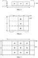
- the build stations 35 may be arranged in various configurations relative to the resin support 122. Example configurations are shown in FIGS. 5-7 .
- FIG. 5 illustrates a configuration in which plurality of build stations 35 are aligned in series relative to a direction of movement of the resin support 122. This may also be described as an upstream/downstream relationship.
- the resin support 122 has an overall working length "L” sufficient to accommodate the build stations 35 plus some additional area as required for the material depositor 30.
- the resin support 122 has an overall width "W" wide enough to accommodate the build area of a single build station 35.
- FIG. 6 illustrates a configuration in which build stations 35 are aligned in parallel relative to a direction of movement of a resin support 222. This may also be described as a parallel or side-by-side relationship.
- the resin support 222 has an overall working length "L” sufficient to accommodate the length of one build station 35 plus some additional area as required for the material depositor 30.
- the resin support 122 has an overall width "W" wide enough to accommodate the combined width of the plurality of build stations 35.
- FIG. 7 illustrates a configuration which a plurality of build stations 35 are arrayed in a series-parallel relationship. This may also be described as a two-dimensional array having rows and columns.
- the resin support 322 has an overall working length "L” sufficient to accommodate the length of the plurality of build stations plus some additional area as required for the material depositor 30.
- the resin support 322 has an overall width "W" wide enough to accommodate the combined width of the plurality of build stations 35.
- resin R may be applied to the resin support 222, 322 as a series of parallel "lanes" 223, 323, respectively, where one lane 223, 323 is provided for each corresponding column of build stations 35. This avoids wasting resin R applied in the spaces between the build stations 35. Furthermore, the width of the lanes may be varied per layer in accordance with the width of the component 65 being built.
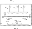
- FIG. 8 illustrates a machine 200 having a plurality of build stations 35 generally similar to machine 100 and including a resin support 122.
- a single radiant energy apparatus 116 e.g. a projector as described above
- the machine 200 is further provided with some image shifting means for directing radiant energy from the radiant energy apparatus 116 to the build stations 35.
- One possible image shifting means comprises beam steering optics 202, for example one or more lenses 204 connected to actuators 206.
- the beam steering optics 202 are operable to receive the patterned image from the radiant energy apparatus 116 and direct it to a selected one of the build stations 35.
- the operation of the beam steering optics 202 is arranged so that images can be projected to different build stations 35 sequentially or at different times.
- Another possible image shifting means is physical movement of the radiant energy apparatus 116.
- it could be mounted to an actuator 208 (e.g. a ballscrew electric actuator, linear electric actuator, pneumatic cylinder, hydraulic cylinder, or delta drive) configured to selectively move the radiant energy apparatus 116 into alignment with a selected one of the build stations 35.
- an actuator 208 e.g. a ballscrew electric actuator, linear electric actuator, pneumatic cylinder, hydraulic cylinder, or delta drive
- FIG. 9 illustrates a machine 300 having a plurality of build stations 35 generally similar to machine 100 and including a resin support 122.
- a single radiant energy apparatus 116 e.g. a projector as described above
- the machine 300 is further provided with beam splitting optics, for example one or more prisms 304 and lenses 306.
- the beam splitting optics are operable to receive the patterned image from the radiant energy apparatus 116 and direct it all or a group of build stations 35 simultaneously.
- FIGS. 8 and 9 can be combined in various ways.
- the build stations 35 are configured in a two-dimensional array as shown in FIG. 7
- a single radiant energy apparatus could be provided with beam splitting optics as described in FIG. 9 for a single row or column of the build stations 35.
- Image shifting means could then be used to align the radiant energy patterned image from the radiant energy apparatus 116 with adjacent rows or columns of the build stations 35.
- the basic build cycle for machines 100, 200, 300 having multiple build stations 35 to form a component 65 is substantially as described above for each individual build station 35.
- the provision of multiple build stations 35 permits variations in the overall process cycle, in particular how the resin R is provided and cycled through the build stations 35.
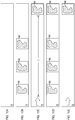
- FIG. 10A shows a clean layer of uncured resin R.
- a component layer 66 is formed by selective curing at each of the spaced-apart build stations 35, FIG. 10B .
- the resin support 122 is then advanced its full working length L to expose fresh uncured resin R, FIG. 10C .
- the selective curing at each of the spaced-apart build stations 35 is repeated as shown in FIG. 10D , followed by again advancing the resin support 122 its full working length L, FIG. 10E .
- FIG. 11A shows a clean layer of uncured resin R.
- a component layer 66 is formed by selective curing at each of the spaced-apart build stations 35, FIG. 11B .
- the resin support 122 is then advanced and increment approximately equal to the length of one build station 35, FIG. 11C .
- the selective curing in each of the spaced-apart build stations 35 is repeated and shown in FIG. 11D .
- This step may be followed by advancing the resin support 122 its full working length L to expose fresh uncured resin R, FIG. 11E .
- This cycle spaces the component layers more closely and tends to avoid waste of resin R.
- multiple build stations 35 are provided using a single resin support 122, and single or multiple radiant energy apparatuses 116 are provided.
- an additive manufacturing machine may incorporate multiple build stations and multiple resin supports all collectively sharing one radiant energy apparatus 116.
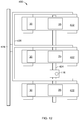
- FIG. 12 illustrates a machine 400 having a plurality of build stations 35 generally similar to machine 10.
- Each build station 35 is associated with an individual resin support 422 (e.g. foil, plate, or vat).
- Each resin support 422 may be provided with an individual material depositor 30, or a shared material depositor may be used.
- a single radiant energy apparatus 116 e.g. a projector as described above
- Means are provided for physically moving the radiant energy apparatus 116.
- the radiant energy apparatus 116 could be mounted to an actuator 424 (e.g. a ballscrew electric actuator, linear electric actuator, pneumatic cylinder, hydraulic cylinder, or delta drive) configured to selectively move the radiant energy apparatus 116 into alignment with a selected one of the build stations 35.
- actuator 424 e.g. a ballscrew electric actuator, linear electric actuator, pneumatic cylinder, hydraulic cylinder, or delta drive
- means may be provided for moving the other components of the machine 10 (i.e. build stations 35, resin supports 22, and material depositors 30).
- these other components are mounted to a support frame 426 which is in turn mounted to an actuator 428.
- the actuator 428 is configured to selectively move the support frame 426 and attached components into alignment with the radiant energy apparatus 116.
- FIG. 13 illustrates a machine 500 having a plurality of build stations 35 generally similar to machine 10.
- Each build station 35 is associated with an individual resin support 522 (e.g. foil, plate, or vat).
- Each resin support 522 may be provided with an individual material depositor 30, or a shared material depositor may be used.
- a single radiant energy apparatus 116 e.g. a projector as described above
- Means are provided for directing the image.
- One possible image shifting means comprises beam steering optics, for example one or more lenses 504 connected to actuators 506.
- the beam steering optics are operable to receive the patterned image from the radiant energy apparatus 116 and direct it to a selected one of the build stations 35.
- the operation of the beam steering optics is arranged so that images can be projected to different build stations 35 in sequence or at different times.
- FIG. 14 illustrates a machine 600 having a plurality of build stations 35 generally similar to machine 10.
- Each build station 35 is associated with an individual resin support 622 (e.g. foil, plate, or vat).
- Each resin support 622 may be provided with an individual material depositor 30, or a shared material depositor may be used.
- a single radiant energy apparatus 116 e.g. a projector as described above
- the machine 600 is further provided with beam splitting optics, for example one or more prisms 604 and lenses 66 The beam splitting optics are operable to receive the patterned image from the radiant energy apparatus 116 and direct it all or a group of build stations 35.
- the build stations 35 may be operated in unison or independently.
- two or more stages 14 can move simultaneously, or sequentially.
- one or more build stations 35 could be turned off completely for maintenance, or because they are not needed for a particular build.
- the method and apparatus described herein has several advantages over the prior art. In particular, it will permit increasing additive manufacturing production rate and scale while reducing the cost and complexity of the machines.
Abstract
Description
- This invention relates generally to additive manufacturing, and more particularly to methods and apparatus for additive manufacturing using multiple build stations with shared components.
- Additive manufacturing is a process in which material is built up layer-by-layer to form a component. Stereolithography is a type of additive manufacturing process which employs a tank of liquid radiant-energy curable photopolymer "resin" and a curing energy source such as a laser. Similarly, DLP 3D printing employs a two-dimensional image projector to build components one layer at a time. For each layer, the projector flashes a radiation image of the cross-section of the component on the surface of the liquid or through a transparent object which defines a constrained surface of the resin. Exposure to the radiation cures and solidifies the pattern in the resin and joins it to a previously-cured layer. Other types of additive manufacturing processes utilize other types of radiant energy sources to solidify patterns in resin.
- Another prior art method is a so-called "tape casting" process. In this process, a resin is deposited onto a flexible radiotransparent tape that is fed out from a supply reel. An upper plate lowers on to the resin, compressing it between the tape and the upper plate and defining a layer thickness. Radiant energy is used to cure the resin through the radiotransparent tape. Once the curing of the first layer is complete, the upper plate is retracted upwards, taking the cured material with it. The tape is then advanced to expose a fresh clean section, ready for additional resin.
- One problem with existing additive manufacturing processes is that each machine has a limited physical capacity and requires multiple components, thus limiting the ability to scale up production economically.
- This problem is addressed by an additive manufacturing apparatus and method in which one or more of the components are shared by multiple build stations.
- According to one aspect of the technology described herein, an additive manufacturing machine includes: a resin support which has at least a portion which is transparent, wherein the resin support defines a build surface; a material depositor operable to deposit a resin which is radiant-energy-curable onto the build surface; at least two build stations, each build station including: a stage positioned adjacent the build surface and configured to hold a stacked arrangement of the resin; one or more actuators operable to manipulate a relative position of the stage and the build surface; and at least one radiant energy apparatus positioned opposite to the stage, and operable to generate and project radiant energy in a predetermined pattern.
- According to another aspect of the technology described herein, a method for producing a component layer-by-layer includes: providing a machine including: a resin support which has at least a portion which is transparent, wherein the resin support defines a build surface; and at least two build stations, each build station including: a stage positioned adjacent the build surface and configured to hold a stacked arrangement of one or more cured layers of a radiant-energy-curable resin; and one or more actuators operable to manipulate a relative position of the stage and the build surface; executing a build cycle, including the steps of: depositing on the build surface the resin, positioning the stages relative to the build surface so as to define a layer increment in the resin on the build surface; selectively curing the resin on the build surface using an application of radiant energy in a specific pattern so as to define the geometry of a cross-sectional layer of a component for each of the stages; moving the build surface and the stages relatively apart so as to separate the component from the build surface; and repeating the cycle, for a plurality of layers, until the components are complete.
- According to another aspect of the technology described herein, an additive manufacturing machine includes: two or more resin supports, each resin support having at least a portion which is transparent, wherein each resin support defines a build surface; a material depositor operable to deposit a resin which is radiant-energy-curable onto the resin supports; a build station for each resin support, each build station including: a stage positioned adjacent the build surface and configured to hold a stacked arrangement of one or more cured layers the resin; one or more actuators operable to manipulate a relative position of the stage and the build surface; and a radiant energy apparatus disposed opposite to the stages and operable to generate and project radiant energy in a predetermined pattern; and means for delivering radiant energy from the radiant energy apparatus to each of the build stations.
- According to another aspect of the technology described herein, a method for producing a component layer-by-layer includes: providing a machine including: two or more resin supports, each resin support having at least a portion which is transparent, wherein each resin support defines a build surface; a build station for each resin support, each build station including: a stage positioned adjacent the build surface and configured to hold a stacked arrangement of one or more cured layers of a radiant-energy-curable resin; one or more actuators operable to manipulate a relative position of the stage and the build surface; a radiant energy apparatus disposed opposite to the stages and operable to generate and project radiant energy in a predetermined pattern; and means for delivering radiant energy from the radiant energy apparatus to each of the build stations; executing a build cycle, including the steps of: depositing on the build surfaces the resin; positioning each of the stages relative to the corresponding build surfaces so as to define a layer increment in the resin on the build surface; selectively curing the resin on the build surface using an application of radiant energy in a specific pattern so as to define the geometry of a cross-sectional layer of a component for each of the stages; moving the build surfaces and the stages relatively apart so as to separate the components from the build surfaces; and repeating the cycle, for a plurality of layers, until the components are complete.
- The invention may be best understood by reference to the following description taken in conjunction with the accompanying drawing figures in which:
-
FIG. 1 is a schematic side view of an exemplary prior art additive manufacturing apparatus; -
FIG. 2 is a schematic diagram of an alternative radiant energy apparatus for use with the additive manufacturing apparatus ofFIG. 1 ; -
FIG. 3 is a schematic top plan view of a layer of a component being built; -
FIG. 4 is a schematic side view of an exemplary additive manufacturing apparatus having multiple build stations; -
FIG. 5 is a schematic top plan view diagram showing a plurality of build stations arranged in a series configuration over a resin support; -
FIG. 6 is a schematic top plan view diagram showing a plurality of build stations arranged in a side-by side configuration across the width of a resin support; -
FIG. 7 is a schematic top plan view diagram showing a plurality of build stations arranged in a two-dimensional array over a resin support; -
FIG. 8 is a schematic side view of an alternative embodiment of an additive manufacturing apparatus having multiple build stations; -
FIG. 9 is a schematic side view of an alternative embodiment of an additive manufacturing apparatus having multiple build stations; -
FIGS. 10A-10E are sequential top view schematic diagrams showing an additive build sequence; -
FIGS. 11A-11E are sequential top view schematic diagrams showing an additive build sequence; -
FIG. 12 is a schematic top plan view of an exemplary additive manufacturing apparatus including multiple build stations and multiple resin supports with a shared radiant energy source; -
FIG. 13 is a schematic top plan view of an alternative additive manufacturing apparatus including multiple build stations and multiple resin supports with a shared radiant energy source; and -
FIG. 14 is a schematic top plan view of another alternative additive manufacturing apparatus including multiple build stations and multiple resin supports with a shared radiant energy source. - In general, an additive manufacturing machine includes a resin handling assembly, a stage, and a radiant energy apparatus. Several embodiments are disclosed herein, in which one or more of those components are shared for a plurality of build stations. Referring to the drawings wherein identical reference numerals denote the same elements throughout the various views,
FIG. 1 illustrates schematically an example of one known type ofadditive manufacturing machine 10. Basic components of theexemplary machine 10 include aresin handling assembly 12, astage 14, and aradiant energy apparatus 16. - In the illustrated example, the
resin handling assembly 12 is a "tape casting"-type device. Theresin handling assembly 12 includes spaced-apart rollers 20 with a flexible polymeric tape orfoil 22 extending therebetween. A portion of thefoil 22 is supported from underneath by asupport plate 24. Suitable mechanical supports (frames, brackets, etc. - not shown) would be provided for therollers 20 andsupport plate 24. Thefoil 22 is an example of a "resin support". - Both of the
support plate 24 and thefoil 22 are transparent or include a portion or portions that are transparent. As used herein, the term "transparent" refers to a material which allows radiant energy of a selected wavelength to pass through. For example, as described below, the radiant energy used for curing could be ultraviolet light or laser light in the visible spectrum. Non-limiting examples of transparent materials include polymers, glass, and crystalline minerals such as sapphire or quartz. - Appropriate means such as motors, actuators, feedback sensors, and/or controls of a known type (not shown) would be provided for driving the
rollers 20 in such a manner so as to maintain thefoil 22 tensioned between therollers 20 and to wind thefoil 22 from one of therollers 20 to theother roller 20. - The
foil 22 extending between therollers 20 defines a "build surface" 26 which is shown as being planar, but could alternatively be arcuate (depending on the shape of the support plate 24). For purposes of convenient description, thebuild surface 26 may be considered to be oriented parallel to an X-Y plane of themachine 10, and a direction perpendicular to the X-Y plane is denoted as a Z-direction (X, Y, and Z being three mutually perpendicular directions). - The
build surface 26 may be configured to be "non-stick", that is, resistant to adhesion of cured resin. The non-stick properties may be embodied by a combination of variables such as the chemistry of thefoil 22, its surface finish, and/or applied coatings. In one example, a permanent or semi-permanent non-stick coating may be applied. One non-limiting example of a suitable coating is polytetrafluoroethylene ("PTFE"). In one example, all or a portion of thefirst build surface 26 may incorporate a controlled roughness or surface texture (e.g. protrusions, dimples, grooves, ridges, etc.) with nonstick properties. In one example, thefoil 22 may be made in whole or in part from an oxygen-permeable material. - For reference purposes, an area or volume immediately surrounding the location of the
foil 22 is defined as a "build zone", labeled 28. - Some means are provided for applying or depositing resin R to the
build surface 26 in a generally uniform layer.FIG. 1 shows schematically amaterial depositor 30 which would be understood to include a reservoir for material communicating with the material outlet such as a slot or aperture (not shown). Conventional means such as a doctor blade (not shown) may be used to control the thickness of resin R applied to thefoil 22, as thefoil 22 passes under thematerial depositor 30. - The
resin handling assembly 12 shown inFIG. 1 is merely an example. It will be understood that the principles described herein may be used with any type of resin support. Nonlimiting examples of such resin supports include foils, tapes, plates, and single-layer vats. - The
stage 14 is a structure defining a planar upper surface 32 which is capable of being oriented parallel to thebuild surface 26. Some means are provided for moving thestage 14 relative to theresin handling assembly 12 parallel to the Z-direction. InFIG. 1 , the movement means are depicted schematically as a simplevertical actuator 34 connected between thestage 14 and astatic support 36, with the understanding that devices such as ballscrew electric actuators, linear electric actuators, pneumatic cylinders, hydraulic cylinders, or delta drives may be used for this purpose. In addition to, or as an alternative to, making thestage 14 movable, thefoil 22 could be movable parallel to the Z-direction. - For the purposes of the present invention, the
stage 14 and the associated movement means such as avertical actuator 34 may be considered to be a "build station", referred to generally atreference numeral 35. - The
radiant energy apparatus 16 may comprise any device or combination of devices operable to generate and project radiant energy on the resin R in a suitable pattern and with a suitable energy level and other operating characteristics to cure the resin R during the build process, described in more detail below. - In one exemplary embodiment as shown in
FIG. 1 , theradiant energy apparatus 16 may comprise a "projector" 38, used herein generally to refer to any device operable to generate a radiant energy patterned image of suitable energy level and other operating characteristics to cure the resin R. As used herein, the term "patterned image" refers to a projection of radiant energy comprising an array of individual pixels. Non-limiting examples of patterned imaged devices include a DLP projector or another digital micromirror device, a 2D array of LEDs, a 2D array of lasers, or optically addressed light valves. In the illustrated example, theprojector 38 includes aradiant energy source 40 such as a UV lamp, animage forming apparatus 42 operable to receive asource beam 44 from the radiant energy source and generate apatterned image 46 to be projected onto the surface of the resin R, and optionally focusingoptics 48, such as one or more lenses. - The
radiant energy source 40 may comprise any device operable to generate a beam of suitable energy level and frequency characteristics to cure the resin R. In the illustrated example, the radiant energy source comprises a UV flash lamp. - The
image forming apparatus 42 may include one or more mirrors, prisms, and/or lenses and is provided with suitable actuators, and arranged so that thesource beam 44 from theradiant energy source 40 can be transformed into a pixelated image in an X-Y plane coincident with the surface of the resin R. In the illustrated example, theimage forming apparatus 42 may be a digital micro-mirror device. For example, theprojector 38 may be a commercially-available Digital Light Processing ("DLP") projector. - As an option, the
projector 38 may incorporate additional means (not shown) such as actuators, mirrors, etc. configured to selectively move the image forming apparatus or other part of theprojector 38, with the effect of rastering or shifting the location of the patterned image on thebuild surface 26. Stated another way, the patterned image may be moved away from a nominal or starting location. This permits a single image forming apparatus to cover a larger build area, for example. Means for mastering or shifting the patterned image from the image forming apparatus are commercially available. This type of image projection may be referred to herein as a "tiled image". - In another exemplary embodiment as shown in
FIG. 2 , in addition to other types of radiant energy devices, theradiant energy apparatus 16 may comprise a "scanned beam apparatus" 50 used herein to refer generally to refer to any device operable to generate a radiant energy beam of suitable energy level and other operating characteristics to cure the resin R and to scan the beam over the surface of the resin R in a desired pattern. In the illustrated example, the scannedbeam apparatus 50 comprises aradiant energy source 52 and abeam steering apparatus 54. - The
radiant energy source 52 may comprise any device operable to generate a beam of suitable power and other operating characteristics to cure the resin R. Non-limiting examples of suitable radiant energy sources include lasers or electron beam guns. - The
beam steering apparatus 54 may include one or more mirrors, prisms, and/or lenses and may be provided with suitable actuators, and arranged so that abeam 56 from theradiant energy source 52 can be focused to a desired spot size and steered to a desired position in plane coincident with the surface of the resin. Thebeam 56 may be referred to herein as a "build beam". Other types of scanned beam apparatus may be used. For example, scanned beam sources using multiple build beams are known, as are scanned beam sources in which the radiant energy source itself is movable by way of one or more actuators. - The
machine 10 may include acontroller 60. Thecontroller 60 inFIG. 1 is a generalized representation of the hardware and software required to control the operation of themachine 10, including some or all of theresin handling assembly 12, thestage 14, theradiant energy apparatus 16, the imaging apparatus 18, and the various actuators described above. Thecontroller 60 may be embodied, for example, by software running on one or more processors embodied in one or more devices such as a programmable logic controller ("PLC") or a microcomputer. Such processors may be coupled to process sensors and operating components, for example, through wired or wireless connections. The same processor or processors may be used to retrieve and analyze sensor data, for statistical analysis, and for feedback control. Numerous aspects of themachine 10 may be subject to closed-loop control. For example, sensors could be used to monitor position, displacement, or movement of any of the components. Process sensors could be used to monitor output power or frequency characteristics of theradiant energy apparatus 16, or forces acting on the apparatus (e.g.,stage 14 or foil 22). Imaging sensors (e.g. machine vision) could be used to observe the deposition or curing process. Information from any of the sensors could be used to monitor, control, or automate some or all of the operation of themachine 10, in conjunction with appropriate programming of thecontroller 60. - Optionally, the components of the
machine 10 may be surrounded by ahousing 62, which may be used to provide a shielding or inert gas atmosphere usinggas ports 64. Optionally, pressure within the housing could be maintained at a desired level greater than or less than atmospheric. Optionally, the housing could be temperature and/or humidity controlled. Optionally, ventilation of the housing could be controlled based on factors such as a time interval, temperature, humidity, and/or chemical species concentration. - The resin R comprises a material which is radiant-energy curable and which is capable of adhering or binding together the filler (if used) in the cured state. As used herein, the term "radiant-energy curable" refers to any material which solidifies in response to the application of radiant energy of a particular frequency and energy level. For example, the resin R may comprise a known type of photopolymer resin containing photo-initiator compounds functioning to trigger a polymerization reaction, causing the resin to change from a liquid state to a solid state. Alternatively, the resin R may comprise a material which contains a solvent that may be evaporated out by the application of radiant energy. The uncured resin R may be provided in solid (e.g. granular) or liquid form including a paste or slurry.
- The resin R is preferably a relatively high viscosity fluid that will not "slump" or run off during the build process. The composition of the resin R may be selected as desired to suit a particular application. Mixtures of different compositions may be used.
- The resin R may be selected to have the ability to out-gas or burn off during further processing, such as the sintering process described below.
- The resin R may incorporate a filler. The filler may be pre-mixed with resin R, then loaded into the
material depositor 30. The filler comprises particles, which are conventionally defined as "a very small bit of matter". The filler may comprise any material which is chemically and physically compatible with the selected resin R. The particles may be regular or irregular in shape, may be uniform or non-uniform in size, and may have variable aspect ratios. For example, the particles may take the form of powder, of small spheres or granules, or may be shaped like small rods or fibers. - The composition of the filler, including its chemistry and microstructure, may be selected as desired to suit a particular application. For example, the filler may be metallic, ceramic, polymeric, and/or organic. Other examples of potential fillers include diamond, silicon, and graphite. Mixtures of different compositions may be used. In one example, the filler composition may be selected for its electrical or electromagnetic properties, e.g. it may specifically be an electrical insulator, a dielectric material, or an electrical conductor. It may be magnetic.
- The filler may be "fusible", meaning it is capable of consolidation into a mass upon via application of sufficient energy. For example, fusibility is a characteristic of many available powders including but not limited to: polymeric, ceramic, glass, and metallic.
- The proportion of filler to resin R may be selected to suit a particular application. Generally, any amount of filler may be used so long as the combined material is capable of flowing and being leveled, and there is sufficient resin R to hold together the particles of the filler in the cured state.
- Examples of the operation of the
machine 10 will now be described in detail with reference toFIG 1 . It will be understood that, as a precursor to producing a component and using themachine 10, acomponent 65 is software modeled. e.g., in terms of a tool (energy source raster) path or as a stack of planar layers arrayed along the Z-axis. Depending on the type of curing method used, each layer may be divided into a grid of pixels. Theactual component 65 may be modeled and/or manufactured as a stack of dozens or hundreds of layers. Suitable software modeling processes are known in the art. - Initially, the
build zone 28 is prepared with resin R on thebuild surface 26. For example, thematerial depositor 30 may be used to deposit resin R over thebuild surface 26 of thefoil 22. - Different materials may also be supplied to the
build surface 26, at different times during the build (i.e. the material combination of the resin may be changed one or more times during the build). More than one material may also be supplied to different areas on a givenbuild surface 26, at the same time. Optionally, any of the individual layers may comprise two or more material combinations.FIG. 3 illustrates anexemplary layer 66 showing a cross-section of thecomponent 65 superimposed thereupon. Thelayer 66 is divided into afirst section 68 including a first combination of resin R and filler, and asecond section 70 including a second combination of resin R and filler. A dashedline 72 indicates the division between the twosections - After the material is deposited, the machine 10 (or parts thereof) is configured or positioned to define a selected layer increment relative the
build surface 26. The layer increment is defined by some combination of the thickness to which the resin R is applied and the operation of thestage 14. For example, thestage 14 could be positioned such that the upper surface 32 is just touching the applied resin R, or thestage 14 could be used to compress and displace the resin R to positively define the layer increment. The layer increment affects the speed of the additive manufacturing process and the resolution of thecomponent 65. The layer increment can be variable, with a larger layer increment being used to speed the process in portions of acomponent 65 not requiring high accuracy, and a smaller layer increment being used where higher accuracy is required, at the expense of process speed. - Once the resin R has been applied and the layer increment defined, the
radiant energy apparatus 16 is used to cure a two-dimensional cross-section or layer of thecomponent 65 being built. - Where a
projector 38 is used, theprojector 38 projects a patterned image representative of the cross-section of thecomponent 65 through thesupport plate 24 andfoil 22 to the resin R. This process is referred to herein as "selective" curing. It will be understood that photopolymers undergo degrees of curing. In many cases, theradiant energy apparatus 16 would not fully cure the resin R. Rather, it would partially cure the resin R enough to "gel" and then a post-cure process (described below) would cure the resin R to whatever completeness it can reach. It will also be understood that, when a multi-layer component is made using this type of resin R, the energy output of theradiant energy apparatus 16 may be carefully selected to partially cure or "undercure" a previous layer, with the expectation that when the subsequent layer is applied, the energy from that next layer will further the curing of the previous layer. In the process described herein, the term "curing" or "cured" may be used to refer to partially-cured or completely-cured resin R. During the curing process, radiant energy may be supplied to a given layer in multiple steps (e.g. multiple flashes) and also may be supplied in multiple different patterns for a given layer. This allows different amounts of energy to be applied to different parts of a layer. - Once curing of the first layer is complete, the
stage 14 is separated from thebuild surface 26, for example by raising thestage 14 using thevertical actuator 34. It will be understood that the resin R and/or cured layer do not necessarily join, stick, or bond with thebuild surface 26. Accordingly, as used herein the term "separate" refers to the process of moving two elements apart from each other and does not necessarily imply the act of breaking a bond or detaching one element from another. - Subsequent to separation, the
build surface 26 may be cleaned or otherwise rejuvenated and prepared for re-use. For example, advancing thefoil 22 provides a clean surface. As thefoil 22 advances, thematerial depositor 30 would be used to apply resin R to thebuild surface 26 to ready it for curing again. - After separation, the
component 65 and/or thestage 14 may be cleaned to remove uncured resin R, debris, or contaminants between curing cycles. The cleaning process may be used for the purpose of removing resin R that did not cure or resin R that did not cure enough to gel during the selective curing step described above. For example, it might be desired to clean thecomponent 65 and/or thestage 14 to ensure that no additional material or material contamination is present in thefinal component 65. For example, cleaning could be done by contacting thecomponent 65 and/or thestage 14 with a cleaning fluid such as a liquid detergent or solvent. - This cycle of preparing the
build surface 26, optionally imaging deposited resin R, incrementing a layer, selectively curing, separating thecomponent 65 from thebuild surface 26, imaging the resin R and cleaning thecomponent 65 and/orstage 14 would be repeated as necessary until theentire component 65 is complete. - Where a scanned beam apparatus is used for the build cycle described above, instead of a projector, the
radiant energy source 52 emits abuild beam 56 and thebeam steering apparatus 54 is used to cure the resin R by steering a focal spot of thebuild beam 56 over the exposed resin R in an appropriate pattern. - Optionally, a scanned beam apparatus may be used in combination with a projector. For example, a scanned beam apparatus may be used to apply radiant energy (in addition to that applied by the projector) by scanning one or multiple beams over the surface of the uncured resin R. This may be concurrent or sequential with the use of the projector.
- Either curing method (projector or scanned) results in a
component 65 in which the filler (if used) is held in a solid shape by the cured resin R. This component may be usable as an end product for some conditions. Subsequent to the curing step, thecomponent 65 may be removed from thestage 14. - If the end product is intended to be composed of the filler (e.g. purely ceramic, glass, metallic, diamond, silicon, graphite, etc.), the
component 65 may be treated to a conventional sintering process to burn out the resin R and to consolidate the ceramic or metallic particles. Optionally, a known infiltration process may be carried out during or after the sintering process, in order to fill voids in the component with a material having a lower melting temperature than the filler. The infiltration process improves component physical properties. - The above-described
machine 10 incorporates asingle build station 35. The productivity of an additive manufacturing machine may be increased and its cost and complexity may be decreased using an apparatus of the same general type in whichmultiple build stations 35 are provided, such that the apparatus can form multiple layers simultaneously, where themultiple build stations 35 share at least one component of the overall machine. - In one basic embodiment, an additive manufacturing machine includes a plurality of
build stations 35 sharing a common resin support. - For example,
FIG. 4 illustrates a machine 100 having a plurality ofbuild stations 35 arranged in proximity to asingle resin support 122 such as a foil similar to foil 22 described above. A portion of theresin support 122 is supported from underneath by a support plate 124. The machine 100 is generally similar tomachine 10, and components or portions of machine 100 not specifically described may be considered to be identical to corresponding components of themachine 10. In the embodiment ofFIG. 4 , an individual radiant energy apparatus 116 (e.g. a projector as described above) is provided for eachbuild station 35. - Optionally, means may be provided for controlling lift-up of the
resin support 122 during the separation step of the build process (where the resin support is a foil). For example, one or more restraints 117 (e.g. long or short bars or rollers) may be provided which extend across all or some portion of theresin support 122. They may contact theresin support 122 or be positioned some distance above it. Therestraints 117 may be fixed or moveable. They may extend in any direction across theresin support 122. - The build stations 35 (and associated radiant energy sources 116) may be arranged in various configurations relative to the
resin support 122. Example configurations are shown inFIGS. 5-7 . -
FIG. 5 illustrates a configuration in which plurality ofbuild stations 35 are aligned in series relative to a direction of movement of theresin support 122. This may also be described as an upstream/downstream relationship. In this configuration, theresin support 122 has an overall working length "L" sufficient to accommodate thebuild stations 35 plus some additional area as required for thematerial depositor 30. Theresin support 122 has an overall width "W" wide enough to accommodate the build area of asingle build station 35. -
FIG. 6 illustrates a configuration in which buildstations 35 are aligned in parallel relative to a direction of movement of aresin support 222. This may also be described as a parallel or side-by-side relationship. In this configuration, theresin support 222 has an overall working length "L" sufficient to accommodate the length of onebuild station 35 plus some additional area as required for thematerial depositor 30. Theresin support 122 has an overall width "W" wide enough to accommodate the combined width of the plurality ofbuild stations 35. -
FIG. 7 illustrates a configuration which a plurality ofbuild stations 35 are arrayed in a series-parallel relationship. This may also be described as a two-dimensional array having rows and columns. In this configuration, theresin support 322 has an overall working length "L" sufficient to accommodate the length of the plurality of build stations plus some additional area as required for thematerial depositor 30. Theresin support 322 has an overall width "W" wide enough to accommodate the combined width of the plurality ofbuild stations 35. - In the configurations shown in
FIG. 6 or FIG. 7 , resin R may be applied to theresin support lane build stations 35. This avoids wasting resin R applied in the spaces between thebuild stations 35. Furthermore, the width of the lanes may be varied per layer in accordance with the width of thecomponent 65 being built. - As an alternative to providing individual
radiant energy apparatuses 116, one or moreradiant energy apparatuses 116 may be shared bymultiple build stations 35. For example,FIG. 8 illustrates amachine 200 having a plurality ofbuild stations 35 generally similar to machine 100 and including aresin support 122. In this embodiment, a single radiant energy apparatus 116 (e.g. a projector as described above) is provided for all of thebuild stations 35. Themachine 200 is further provided with some image shifting means for directing radiant energy from theradiant energy apparatus 116 to thebuild stations 35. One possible image shifting means comprisesbeam steering optics 202, for example one ormore lenses 204 connected to actuators 206. Thebeam steering optics 202 are operable to receive the patterned image from theradiant energy apparatus 116 and direct it to a selected one of thebuild stations 35. The operation of thebeam steering optics 202 is arranged so that images can be projected todifferent build stations 35 sequentially or at different times. - Another possible image shifting means is physical movement of the
radiant energy apparatus 116. For example, it could be mounted to an actuator 208 (e.g. a ballscrew electric actuator, linear electric actuator, pneumatic cylinder, hydraulic cylinder, or delta drive) configured to selectively move theradiant energy apparatus 116 into alignment with a selected one of thebuild stations 35. - As another alternative to providing individual
radiant energy apparatuses 116,FIG. 9 illustrates amachine 300 having a plurality ofbuild stations 35 generally similar to machine 100 and including aresin support 122. In this embodiment, a single radiant energy apparatus 116 (e.g. a projector as described above) is provided for all of thebuild stations 35. Themachine 300 is further provided with beam splitting optics, for example one ormore prisms 304 andlenses 306. The beam splitting optics are operable to receive the patterned image from theradiant energy apparatus 116 and direct it all or a group ofbuild stations 35 simultaneously. - The concepts illustrated in
FIGS. 8 and9 can be combined in various ways. For example, thebuild stations 35 are configured in a two-dimensional array as shown inFIG. 7 , a single radiant energy apparatus could be provided with beam splitting optics as described inFIG. 9 for a single row or column of thebuild stations 35. Image shifting means could then be used to align the radiant energy patterned image from theradiant energy apparatus 116 with adjacent rows or columns of thebuild stations 35. - The basic build cycle for
machines multiple build stations 35 to form acomponent 65 is substantially as described above for eachindividual build station 35. However, the provision ofmultiple build stations 35 permits variations in the overall process cycle, in particular how the resin R is provided and cycled through thebuild stations 35. - One example of the potential process is shown in
FIGS. 10A-10E. FIG. 10A shows a clean layer of uncured resin R. Initially, acomponent layer 66 is formed by selective curing at each of the spaced-apartbuild stations 35,FIG. 10B . Theresin support 122 is then advanced its full working length L to expose fresh uncured resin R,FIG. 10C . The selective curing at each of the spaced-apartbuild stations 35 is repeated as shown inFIG. 10D , followed by again advancing theresin support 122 its full working length L,FIG. 10E . - Another example of a potential cycle is shown in
FIGS. 11A-11E. FIG. 11A shows a clean layer of uncured resin R. Initially, acomponent layer 66 is formed by selective curing at each of the spaced-apartbuild stations 35,FIG. 11B . Theresin support 122 is then advanced and increment approximately equal to the length of onebuild station 35,FIG. 11C . The selective curing in each of the spaced-apartbuild stations 35 is repeated and shown inFIG. 11D . This results an array of cured component layers 66 spaced closely adjacent each other on the resin R. This step may be followed by advancing theresin support 122 its full working length L to expose fresh uncured resin R,FIG. 11E . This cycle spaces the component layers more closely and tends to avoid waste of resin R. - In the embodiments described above,
multiple build stations 35 are provided using asingle resin support 122, and single or multipleradiant energy apparatuses 116 are provided. Alternatively, an additive manufacturing machine may incorporate multiple build stations and multiple resin supports all collectively sharing oneradiant energy apparatus 116. - For example,
FIG. 12 illustrates amachine 400 having a plurality ofbuild stations 35 generally similar tomachine 10. Eachbuild station 35 is associated with an individual resin support 422 (e.g. foil, plate, or vat). Eachresin support 422 may be provided with anindividual material depositor 30, or a shared material depositor may be used. In this embodiment, a single radiant energy apparatus 116 (e.g. a projector as described above) is provided for all of thebuild stations 35. Means are provided for physically moving theradiant energy apparatus 116. For example, theradiant energy apparatus 116 could be mounted to an actuator 424 (e.g. a ballscrew electric actuator, linear electric actuator, pneumatic cylinder, hydraulic cylinder, or delta drive) configured to selectively move theradiant energy apparatus 116 into alignment with a selected one of thebuild stations 35. - Alternatively, means may be provided for moving the other components of the machine 10 (i.e.
build stations 35, resin supports 22, and material depositors 30). In the illustrated example, these other components are mounted to asupport frame 426 which is in turn mounted to anactuator 428. Theactuator 428 is configured to selectively move thesupport frame 426 and attached components into alignment with theradiant energy apparatus 116. - As another alternative to providing individual
radiant energy apparatuses 116,FIG. 13 illustrates amachine 500 having a plurality ofbuild stations 35 generally similar tomachine 10. Eachbuild station 35 is associated with an individual resin support 522 (e.g. foil, plate, or vat). Eachresin support 522 may be provided with anindividual material depositor 30, or a shared material depositor may be used. In this embodiment, a single radiant energy apparatus 116 (e.g. a projector as described above) is provided for all of thebuild stations 35. Means are provided for directing the image. One possible image shifting means comprises beam steering optics, for example one ormore lenses 504 connected to actuators 506. The beam steering optics are operable to receive the patterned image from theradiant energy apparatus 116 and direct it to a selected one of thebuild stations 35. The operation of the beam steering optics is arranged so that images can be projected todifferent build stations 35 in sequence or at different times. - As another alternative to providing individual
radiant energy apparatuses 116,FIG. 14 illustrates amachine 600 having a plurality ofbuild stations 35 generally similar tomachine 10. Eachbuild station 35 is associated with an individual resin support 622 (e.g. foil, plate, or vat). Eachresin support 622 may be provided with anindividual material depositor 30, or a shared material depositor may be used. In this embodiment, a single radiant energy apparatus 116 (e.g. a projector as described above) is provided for all of thebuild stations 35. Themachine 600 is further provided with beam splitting optics, for example one ormore prisms 604 andlenses 66 The beam splitting optics are operable to receive the patterned image from theradiant energy apparatus 116 and direct it all or a group ofbuild stations 35. - For any of the embodiments described herein, the
build stations 35 may be operated in unison or independently. For example, two ormore stages 14 can move simultaneously, or sequentially. Optionally, one ormore build stations 35 could be turned off completely for maintenance, or because they are not needed for a particular build. - The method and apparatus described herein has several advantages over the prior art. In particular, it will permit increasing additive manufacturing production rate and scale while reducing the cost and complexity of the machines.
- The foregoing has described a method and apparatus for additive manufacturing. All of the features disclosed in this specification (including any accompanying claims, abstract and drawings), and/or all of the steps of any method or process so disclosed, may be combined in any combination, except combinations where at least some of such features and/or steps are mutually exclusive.
- Each feature disclosed in this specification (including any accompanying claims, abstract and drawings) may be replaced by alternative features serving the same, equivalent or similar purpose, unless expressly stated otherwise. Thus, unless expressly stated otherwise, each feature disclosed is one example only of a generic series of equivalent or similar features.
- The invention is not restricted to the details of the foregoing embodiment(s). The invention extends to any novel one, or any novel combination, of the features disclosed in this specification (including any accompanying claims, abstract and drawings), or to any novel one, or any novel combination, of the steps of any method or process so disclosed.
- Various aspects and embodiments of the invention are defined by the following clauses:
- 1. An additive manufacturing machine, comprising:
- a resin support which has at least a portion which is transparent, wherein the resin support defines a build surface;
- a material depositor operable to deposit a resin which is radiant-energy-curable onto the build surface;
- at least two build stations, each build station including:
- a stage positioned adjacent the build surface and configured to hold a stacked arrangement of one or more cured layers of the resin;
- one or more actuators operable to manipulate a relative position of the stage and the build surface; and
- at least one radiant energy apparatus positioned opposite to the stage, and operable to generate and project radiant energy in a predetermined pattern.
- 2. The machine of
clause 1 wherein a separate radiant energy apparatus is disposed adjacent each of the two or more build stations. - 3. The machine of
clause 1 wherein a single radiant energy apparatus is provided, the machine further including image shifting means for selectively directing radiant energy from the radiant energy apparatus to one of the at least two build stations. - 4. The machine of clause 3 wherein the image shifting means comprises one or more actuators operable to physically move the radiant energy apparatus relative to the build stations.
- 5. The machine of clause 3 wherein the image shifting means comprises a beam steering apparatus.
- 6. The machine of
clause 1 wherein a single radiant energy apparatus is provided, the machine further including beam splitting optics apparatus operable to direct radiant energy to two or more of the at least two build stations simultaneously. - 7. The machine of
clause 1 wherein the resin support comprises spaced-apart rollers with a flexible foil extending therebetween. - 8. The machine of
clause 1 wherein the two or more build stations are arranged in a series configuration relative to the resin support. - 9. The machine of
clause 1 wherein the two or more build stations are arranged in a side-by-side configuration relative to the resin support. - 10. The machine of
clause 1 wherein the two or more build stations are arranged in a two-dimensional array configuration relative to the resin support. - 11. The machine of
clause 1 wherein the material depositor is configured to apply the resin in one or more lanes, wherein each lane is narrower than an overall width of the resin support. - 12. A method for producing a component layer-by-layer, comprising:
- providing a machine including:
a resin support which has at least a portion which is transparent, wherein the resin support defines a build surface; and - at least two build stations, each build station including:
- a stage positioned adjacent the build surface and configured to hold a stacked arrangement of one or more cured layers of a radiant-energy-curable resin; and
- one or more actuators operable to manipulate a relative position of the stage and the build surface;
- executing a build cycle, including the steps of:
- depositing on the build surface the resin;
- positioning the stages relative to the build surface so as to define a layer increment in the resin on the build surface;
- selectively curing the resin on the build surface using an application of radiant energy in a specific pattern so as to define the geometry of a cross-sectional layer of a component for each of the stages;
- moving the build surface and the stages relatively apart so as to separate the component from the build surface; and
- repeating the cycle, for a plurality of layers, until the components are complete.
- providing a machine including:
- 13. The method of
clause 12 wherein the radiant energy is applied using separate radiant energy apparatus for each of the two or more build stations. - 14. The method of
clause 12 wherein the radiant energy is applied by shifting radiant energy from a single radiant energy apparatus to the at least two build stations at different times. - 15. The method of
clause 14 wherein the radiant energy is shifted by physically moving the radiant energy apparatus relative to the at least two build stations. - 16. The method of
clause 14 wherein the radiant energy is shifted by a beam steering apparatus. - 17. The method of
clause 12 wherein the radiant energy is applied by splitting radiant energy from a single radiant energy apparatus and directing it to the at least two build stations simultaneously. - 18. The method of
clause 12 wherein the two or more build stations are arranged in a series configuration relative to the resin support. - 19. The method of
clause 12 wherein the two or more build stations are arranged in a side-by-side configuration relative to the resin support. - 20. The method of
clause 12 wherein the two or more build stations are arranged in a two-dimensional array configuration relative to the resin support. - 21. The method of
clause 12 wherein the resin is applied resin in one or more lanes, wherein each lane is narrower than an overall width of the resin support. - 22. The method of
clause 12 wherein, between layers of the build cycle, the resin support is advanced to provide uncured resin to each of the build stations. - 23. The method of
clause 22 wherein, between layers of the build cycle, the resin support is advanced to move uncured resin which was previously located between the build stations underneath one or more of the build stations. - 24. The method of
clause 12 wherein a material combination of the resin is changed at least once during the building of the components. - 25. An additive manufacturing machine, comprising:
- two or more resin supports, each resin support having at least a portion which is transparent, wherein each resin support defines a build surface;
- a material depositor operable to deposit a resin which is radiant-energy-curable onto the resin supports;
- a build station for each resin support, each build station including:
- a stage positioned adjacent the build surface and configured to hold a stacked arrangement of one or more cured layers of the resin;
- one or more actuators operable to manipulate a relative position of the stage and the build surface; and
- a radiant energy apparatus disposed opposite to the stages and operable to generate and project radiant energy in a predetermined pattern; and
- means for delivering radiant energy from the radiant energy apparatus to each of the build stations.
- 26. The machine of clause 25 wherein the means for delivering radiant energy comprises one or more actuators operable to physically move the radiant energy apparatus relative to the build stations.
- 27. The machine of clause 25 wherein the means for delivering radiant energy comprises a beam steering apparatus.
- 28. The machine of clause 25 wherein the means for delivering radiant energy includes beam splitting optics operable to direct radiant energy to two or more of the at least two build stations simultaneously.
- 29. The machine of clause 25 wherein the resin support comprises spaced-apart rollers with a flexible foil extending therebetween.
- 30. A method for producing a component layer-by-layer, comprising:
- providing a machine including:
- two or more resin supports, each resin support having at least a portion which is transparent, wherein each resin support defines a build surface;
a build station for each resin support, each build station including:- a stage positioned adjacent the build surface and configured to hold a stacked arrangement of one or more cured layers of a radiant-energy-curable resin;
- one or more actuators operable to manipulate a relative position of the stage and the build surface;
- a radiant energy apparatus disposed opposite to the stages and operable to generate and project radiant energy in a predetermined pattern; and
- means for delivering radiant energy from the radiant energy apparatus to each of the build stations;
- two or more resin supports, each resin support having at least a portion which is transparent, wherein each resin support defines a build surface;
- executing a build cycle, including the steps of:
- depositing on the build surfaces the resin;
- positioning each of the stages relative to the corresponding build surfaces so as to define a layer increment in the resin on the build surface;
- selectively curing the resin on the build surface using an application of radiant energy in a specific pattern so as to define the geometry of a cross-sectional layer of a component for each of the stages;
- moving the build surfaces and the stages relatively apart so as to separate the components from the build surfaces; and
- repeating the cycle, for a plurality of layers, until the components are complete.
- providing a machine including:
- 31. The method of
clause 30 wherein the radiant energy is delivered by shifting radiant energy from the single radiant energy apparatus to the at least two build stations at different times. - 32. The method of
clause 30 wherein the radiant energy is delivered by physically moving the radiant energy apparatus relative to the at least two build stations. - 33. The method of
clause 30 wherein the radiant energy is delivered by a beam steering apparatus. - 34. The method of
clause 30 wherein the radiant energy is delivered by splitting radiant energy from the single radiant energy apparatus and directing it to the at least two build stations simultaneously. - 35. The method of
clause 30 wherein a material combination of the resin is changed at least once during the build.
Claims (15)
- An additive manufacturing machine (10, 100, 200, 300, 400, 500, 600), comprising:a resin support (22, 122, 222, 322, 422, 522, 622) which has at least a portion which is transparent, wherein the resin support (22, 122, 222, 322, 422, 522, 622) defines a build surface (26);a material depositor (30) operable to deposit a resin which is radiant-energy-curable onto the build surface (26);at least two build stations (35), each build station (35) including:a stage (14) positioned adjacent the build surface (26) and configured to hold a stacked arrangement of one or more cured layers of the resin;one or more actuators operable to manipulate a relative position of the stage (14) and the build surface (26); andat least one radiant energy apparatus (16, 116) positioned opposite to the stage (14), and operable to generate and project radiant energy in a predetermined pattern.
- The machine (10, 100, 200, 300,400, 500, 600) of claim 1 wherein a separate radiant energy apparatus (16, 116) is disposed adjacent each of the at least two build stations (35).
- The machine (10, 100, 200, 300, 400, 500, 600) of claim 1 wherein a single radiant energy apparatus (16, 116) is provided, the machine (10, 100, 200, 300, 400, 500, 600) further including image shifting means for selectively directing radiant energy from the radiant energy apparatus (16, 116) to one of the at least two build stations (35).
- The machine (10, 100, 200, 300, 400, 500, 600) of any one of claims 1-3 wherein the at least two build stations (35) are arranged in a series configuration relative to the resin support (22, 122, 222, 322, 422, 522, 622).
- The machine (10, 100, 200, 300, 400, 500, 600) of any one of claims 1-3 wherein the at least two build stations (35) are arranged in a side-by-side configuration relative to the resin support (22, 122, 222, 322, 422, 522, 622).
- The machine (10, 100, 200, 300, 400, 500, 600) of any one of claims 1-3 wherein the at least two build stations (35) are arranged in a two-dimensional array configuration relative to the resin support (22, 122, 222, 322, 422, 522, 622).
- The machine (10, 100, 200, 300, 400, 500, 600) of any one of claims 1-6 wherein the material depositor (30) is configured to apply the resin in one or more lanes, wherein each lane is narrower than an overall width of the resin support (22, 122, 222, 322, 422, 522, 622).
- The additive manufacturing machine (10, 100, 200, 300, 400, 500, 600) of any one of claims 1-7 further comprising:
a second resin support (22, 122, 222, 322, 422, 522, 622) having at least a portion which is transparent, wherein the second resin support (22, 122, 222, 322, 422, 522, 622) defines a second build surface (26), wherein:the material depositor (30) is operable to deposit the resin which is radiant-energy-curable onto the resin support (22, 122, 222, 322, 422, 522, 622) and the second resin support (22, 122, 222, 322, 422, 522, 622); andthe at least two build stations (35) comprises a first build station (35) for the resin support (22, 122, 222, 322, 422, 522, 622) and a second build station (35) for the second resin support (22, 122, 222, 322, 422, 522, 622). - A method for producing a component layer-by-layer, comprising:providing a machine (10, 100, 200, 300, 400, 500, 600) including:
a resin support (22, 122, 222, 322, 422, 522, 622) which has at least a portion which is transparent, wherein the resin support (22, 122, 222, 322, 422, 522, 622) defines a build surface (26); andat least two build stations (35), each build station (35) including:a stage (14) positioned adjacent the build surface (26) and configured to hold a stacked arrangement of one or more cured layers of a radiant-energy-curable resin; andone or more actuators operable to manipulate a relative position of the stage (14) and the build surface (26);executing a build cycle, including the steps of:depositing on the build surface (26) the resin;positioning the stages (14) relative to the build surface (26) so as to define a layer increment in the resin on the build surface (26);selectively curing the resin on the build surface (26) using an application of radiant energy in a specific pattern so as to define the geometry of a cross-sectional layer of a component for each of the stages (14);moving the build surface (26) and the stages (14) relatively apart so as to separate the component from the build surface (26); andrepeating the cycle, for a plurality of layers, until the component is complete. - The method of claim 9 wherein the resin is applied in one or more lanes, wherein each lane is narrower than an overall width of the resin support (22, 122, 222, 322, 422, 522, 622).
- The method of any one of claims 9-10 wherein, between layers of the build cycle, the resin support (22, 122, 222, 322, 422, 522, 622) is advanced to provide uncured resin to each of the build stations (35).
- The method of any one of claims 9-11 wherein, between layers of the build cycle, the resin support (22, 122, 222, 322, 422, 522, 622) is advanced to move uncured resin which was previously located between the build stations (35) underneath one or more of the build stations (35).
- The method of any one of claims 9-12 wherein a material combination of the resin is changed at least once during the building of the components.
- The method of any one of claims 9-13, wherein the machine (10, 100, 200, 300, 400, 500, 600) further includes a second resin support (22, 122, 222, 322, 422, 522, 622) having at least a portion which is transparent, wherein the second resin support (22, 122, 222, 322, 422, 522, 622) defines a second build surface (26), wherein the at least two build stations (35) comprises a first build station (35) for the resin support (22, 122, 222, 322, 422, 522, 622) and a second build station (35) for the second resin support (22, 122, 222, 322, 422, 522, 622).
- The method of claim 14 further comprising shifting radiant energy from a single radiant energy apparatus (16, 116) to the first build station (35) and the second build station (35) at different times.
Priority Applications (1)
| Application Number | Priority Date | Filing Date | Title |
|---|---|---|---|
| EP22203779.8A EP4166305A1 (en) | 2019-03-15 | 2020-03-10 | Method and apparatus for additive manufacturing with shared components |
Applications Claiming Priority (1)
| Application Number | Priority Date | Filing Date | Title |
|---|---|---|---|
| US16/355,144 US11179891B2 (en) | 2019-03-15 | 2019-03-15 | Method and apparatus for additive manufacturing with shared components |
Related Child Applications (2)
| Application Number | Title | Priority Date | Filing Date |
|---|---|---|---|
| EP22203779.8A Division EP4166305A1 (en) | 2019-03-15 | 2020-03-10 | Method and apparatus for additive manufacturing with shared components |
| EP22203779.8A Division-Into EP4166305A1 (en) | 2019-03-15 | 2020-03-10 | Method and apparatus for additive manufacturing with shared components |
Publications (2)
| Publication Number | Publication Date |
|---|---|
| EP3708337A1 true EP3708337A1 (en) | 2020-09-16 |
| EP3708337B1 EP3708337B1 (en) | 2022-12-14 |
Family
ID=69784252
Family Applications (2)
| Application Number | Title | Priority Date | Filing Date |
|---|---|---|---|
| EP22203779.8A Pending EP4166305A1 (en) | 2019-03-15 | 2020-03-10 | Method and apparatus for additive manufacturing with shared components |
| EP20161960.8A Active EP3708337B1 (en) | 2019-03-15 | 2020-03-10 | Method and apparatus for additive manufacturing with shared components |
Family Applications Before (1)
| Application Number | Title | Priority Date | Filing Date |
|---|---|---|---|
| EP22203779.8A Pending EP4166305A1 (en) | 2019-03-15 | 2020-03-10 | Method and apparatus for additive manufacturing with shared components |
Country Status (3)
| Country | Link |
|---|---|
| US (2) | US11179891B2 (en) |
| EP (2) | EP4166305A1 (en) |
| CN (1) | CN111688188A (en) |
Cited By (1)
| Publication number | Priority date | Publication date | Assignee | Title |
|---|---|---|---|---|
| EP4311657A1 (en) * | 2022-07-28 | 2024-01-31 | General Electric Company | Apparatus and methods for additive manufacturing |
Families Citing this family (12)
| Publication number | Priority date | Publication date | Assignee | Title |
|---|---|---|---|---|
| US11840023B2 (en) * | 2019-08-30 | 2023-12-12 | Carbon, Inc. | Mutliphysics model for inverse warping of data file in preparation for additive manufacturing |
| JP2023520187A (en) | 2020-03-25 | 2023-05-16 | オーピーティー インダストリーズ,インコーポレイテッド | Systems, methods and file formats for 3D printing of microstructures |
| CN114905736A (en) * | 2021-02-07 | 2022-08-16 | 源秩科技(上海)有限公司 | Photocuring three-dimensional printing device and printing method |
| DE102021103511A1 (en) | 2021-02-15 | 2022-08-18 | Kulzer Gmbh | Device and method for the simultaneous additive manufacturing of components made of different materials |
| DE102021103739A1 (en) | 2021-02-17 | 2022-08-18 | Te Connectivity Germany Gmbh | Additive manufacturing system with a plurality of manufacturing stations and method for the additive manufacturing of a plurality of workpieces |
| US11865780B2 (en) | 2021-02-26 | 2024-01-09 | General Electric Company | Accumalator assembly for additive manufacturing |
| US11951679B2 (en) | 2021-06-16 | 2024-04-09 | General Electric Company | Additive manufacturing system |
| US11731367B2 (en) | 2021-06-23 | 2023-08-22 | General Electric Company | Drive system for additive manufacturing |
| US11958249B2 (en) | 2021-06-24 | 2024-04-16 | General Electric Company | Reclamation system for additive manufacturing |
| US11958250B2 (en) | 2021-06-24 | 2024-04-16 | General Electric Company | Reclamation system for additive manufacturing |
| US11826950B2 (en) | 2021-07-09 | 2023-11-28 | General Electric Company | Resin management system for additive manufacturing |
| US11813799B2 (en) * | 2021-09-01 | 2023-11-14 | General Electric Company | Control systems and methods for additive manufacturing |
Citations (4)
| Publication number | Priority date | Publication date | Assignee | Title |
|---|---|---|---|---|
| DE102007010624A1 (en) * | 2007-03-02 | 2008-09-04 | Deltamed Gmbh | Layered molding device for generative stereolithographic production layer by layer of three-dimensional parts of a mold, e.g. as a tooth replacement, uses radiation to compact composite substances |
| WO2017100538A1 (en) * | 2015-12-11 | 2017-06-15 | Global Filtration Systems, A Dba Of Gulf Filtration Systems Inc. | Method and apparatus for concurrently making multiple three-dimensional objects from multiple solidifiable materials |
| US20180043619A1 (en) * | 2015-03-20 | 2018-02-15 | Lg Electronics Inc. | 3d printing apparatus |
| EP3453521A1 (en) * | 2017-09-06 | 2019-03-13 | Ackuretta Technologies Pvt. Ltd. | Digital light processing in three-dimensional printing system and method for improving the production rate of 3d printing |
Family Cites Families (223)
| Publication number | Priority date | Publication date | Assignee | Title |
|---|---|---|---|---|
| US5236637A (en) | 1984-08-08 | 1993-08-17 | 3D Systems, Inc. | Method of and apparatus for production of three dimensional objects by stereolithography |
| US4575330A (en) | 1984-08-08 | 1986-03-11 | Uvp, Inc. | Apparatus for production of three-dimensional objects by stereolithography |
| US4752498A (en) | 1987-03-02 | 1988-06-21 | Fudim Efrem V | Method and apparatus for production of three-dimensional objects by photosolidification |
| IL109511A (en) | 1987-12-23 | 1996-10-16 | Cubital Ltd | Three-dimensional modelling apparatus |
| US5126259A (en) | 1987-12-24 | 1992-06-30 | Takeda Chemical Industries, Ltd. | Human b. lymphoblastoid cell, hybridoma, antibody and production of antibody |
| JP2963478B2 (en) | 1988-04-18 | 1999-10-18 | スリーディー、システムズ、インコーポレーテッド | Method and apparatus for forming a three-dimensional object |
| US5182055A (en) | 1988-04-18 | 1993-01-26 | 3D Systems, Inc. | Method of making a three-dimensional object by stereolithography |
| US5059359A (en) | 1988-04-18 | 1991-10-22 | 3 D Systems, Inc. | Methods and apparatus for production of three-dimensional objects by stereolithography |
| US5258146A (en) | 1988-09-26 | 1993-11-02 | 3D Systems, Inc. | Method of and apparatus for measuring and controlling fluid level in stereolithography |
| US5174931A (en) | 1988-09-26 | 1992-12-29 | 3D Systems, Inc. | Method of and apparatus for making a three-dimensional product by stereolithography |
| US5026146A (en) | 1989-04-03 | 1991-06-25 | Hug William F | System for rapidly producing plastic parts |
| JPH03244528A (en) | 1989-09-28 | 1991-10-31 | Three D Syst Inc | Device and method forming substantially flat and solid face for processing planograph |
| US5133987A (en) | 1989-10-27 | 1992-07-28 | 3D Systems, Inc. | Stereolithographic apparatus and method |
| US5387380A (en) | 1989-12-08 | 1995-02-07 | Massachusetts Institute Of Technology | Three-dimensional printing techniques |
| US5204055A (en) | 1989-12-08 | 1993-04-20 | Massachusetts Institute Of Technology | Three-dimensional printing techniques |
| US5626919A (en) | 1990-03-01 | 1997-05-06 | E. I. Du Pont De Nemours And Company | Solid imaging apparatus and method with coating station |
| US5096530A (en) | 1990-06-28 | 1992-03-17 | 3D Systems, Inc. | Resin film recoating method and apparatus |
| US5192559A (en) | 1990-09-27 | 1993-03-09 | 3D Systems, Inc. | Apparatus for building three-dimensional objects with sheets |
| US5126529A (en) | 1990-12-03 | 1992-06-30 | Weiss Lee E | Method and apparatus for fabrication of three-dimensional articles by thermal spray deposition |
| US5207371A (en) | 1991-07-29 | 1993-05-04 | Prinz Fritz B | Method and apparatus for fabrication of three-dimensional metal articles by weld deposition |
| IT1252949B (en) | 1991-09-30 | 1995-07-06 | Gisulfo Baccini | PROCEDURE FOR THE PROCESSING OF GREEN-TAPE TYPE CIRCUITS AND DEVICE ADOPTING THIS PROCEDURE |
| US5203944A (en) | 1991-10-10 | 1993-04-20 | Prinz Fritz B | Method for fabrication of three-dimensional articles by thermal spray deposition using masks as support structures |
| US5432045A (en) | 1992-05-28 | 1995-07-11 | Cmet, Inc. | Photo-solidification modeling apparatus and photo-solidification modeling method having an improved recoating process |
| US5454069A (en) | 1992-08-25 | 1995-09-26 | University Of Kentucky Research Foundation | Process for converting serial image to the sterolithography apparatus (SLA) slice file with automatic base and support generation |
| US6146567A (en) | 1993-02-18 | 2000-11-14 | Massachusetts Institute Of Technology | Three dimensional printing methods |
| JP2706611B2 (en) | 1993-10-14 | 1998-01-28 | 帝人製機株式会社 | Stereolithography method and stereolithography device |
| US5496682A (en) | 1993-10-15 | 1996-03-05 | W. R. Grace & Co.-Conn. | Three dimensional sintered inorganic structures using photopolymerization |
| US5879489A (en) | 1993-11-24 | 1999-03-09 | Burns; Marshall | Method and apparatus for automatic fabrication of three-dimensional objects |
| US6206672B1 (en) | 1994-03-31 | 2001-03-27 | Edward P. Grenda | Apparatus of fabricating 3 dimensional objects by means of electrophotography, ionography or a similar process |
| JPH0853264A (en) | 1994-08-10 | 1996-02-27 | Seiko Epson Corp | Released paper separation structure for adhesive tape with this paper |
| DE19515165C2 (en) | 1995-04-25 | 1997-03-06 | Eos Electro Optical Syst | Device for producing an object using stereolithography |
| US6270335B2 (en) | 1995-09-27 | 2001-08-07 | 3D Systems, Inc. | Selective deposition modeling method and apparatus for forming three-dimensional objects and supports |
| DE69633143T2 (en) | 1995-11-09 | 2005-08-04 | Toyota Jidosha K.K., Toyota | Method and device for producing a 3-D core sand mold by forming layers of sand |
| US5660621A (en) | 1995-12-29 | 1997-08-26 | Massachusetts Institute Of Technology | Binder composition for use in three dimensional printing |
| US5697043A (en) | 1996-05-23 | 1997-12-09 | Battelle Memorial Institute | Method of freeform fabrication by selective gelation of powder suspensions |
| US6596224B1 (en) | 1996-05-24 | 2003-07-22 | Massachusetts Institute Of Technology | Jetting layers of powder and the formation of fine powder beds thereby |
| WO1998006560A1 (en) | 1996-08-08 | 1998-02-19 | Sri International | Apparatus for automated fabrication of three-dimensional objects, and associated methods of use |
| US6051179A (en) | 1997-03-19 | 2000-04-18 | Replicator Systems, Inc. | Apparatus and method for production of three-dimensional models by spatial light modulator |
| US5940674A (en) | 1997-04-09 | 1999-08-17 | Massachusetts Institute Of Technology | Three-dimensional product manufacture using masks |
| JPH115254A (en) | 1997-04-25 | 1999-01-12 | Toyota Motor Corp | Lamination shaping method |
| NL1006059C2 (en) | 1997-05-14 | 1998-11-17 | Geest Adrianus F Van Der | Method and device for manufacturing a shaped body. |
| US6363606B1 (en) | 1998-10-16 | 2002-04-02 | Agere Systems Guardian Corp. | Process for forming integrated structures using three dimensional printing techniques |
| US6401002B1 (en) | 1999-04-29 | 2002-06-04 | Nanotek Instruments, Inc. | Layer manufacturing apparatus and process |
| US6200646B1 (en) | 1999-08-25 | 2001-03-13 | Spectra Group Limited, Inc. | Method for forming polymeric patterns, relief images and colored polymeric bodies using digital light processing technology |
| US6436520B1 (en) | 1999-09-01 | 2002-08-20 | Toda Kogyo Corporation | Magnetic display device |
| DE19948591A1 (en) | 1999-10-08 | 2001-04-19 | Generis Gmbh | Rapid prototyping method and device |
| JP4624626B2 (en) | 1999-11-05 | 2011-02-02 | ズィー コーポレイション | Material system and three-dimensional printing method |
| US6850334B1 (en) | 2000-01-18 | 2005-02-01 | Objet Geometries Ltd | System and method for three dimensional model printing |
| US7300619B2 (en) | 2000-03-13 | 2007-11-27 | Objet Geometries Ltd. | Compositions and methods for use in three dimensional model printing |
| US20010050031A1 (en) | 2000-04-14 | 2001-12-13 | Z Corporation | Compositions for three-dimensional printing of solid objects |
| US6500378B1 (en) | 2000-07-13 | 2002-12-31 | Eom Technologies, L.L.C. | Method and apparatus for creating three-dimensional objects by cross-sectional lithography |
| DE50014868D1 (en) | 2000-09-25 | 2008-01-31 | Voxeljet Technology Gmbh | METHOD FOR MANUFACTURING A COMPONENT IN DEPOSITION TECHNOLOGY |
| NL1016431C2 (en) | 2000-10-18 | 2002-04-22 | Univ Nijmegen | Method for separating a film and a substrate. |
| US6471800B2 (en) | 2000-11-29 | 2002-10-29 | Nanotek Instruments, Inc. | Layer-additive method and apparatus for freeform fabrication of 3-D objects |
| US6376148B1 (en) | 2001-01-17 | 2002-04-23 | Nanotek Instruments, Inc. | Layer manufacturing using electrostatic imaging and lamination |
| US6896839B2 (en) | 2001-02-07 | 2005-05-24 | Minolta Co., Ltd. | Three-dimensional molding apparatus and three-dimensional molding method |
| GB0103754D0 (en) | 2001-02-15 | 2001-04-04 | Vantico Ltd | Three-dimensional structured printing |
| US6852272B2 (en) | 2001-03-07 | 2005-02-08 | Advanced Ceramics Research, Inc. | Method for preparation of metallic and ceramic foam products and products made |
| US6780368B2 (en) | 2001-04-10 | 2004-08-24 | Nanotek Instruments, Inc. | Layer manufacturing of a multi-material or multi-color 3-D object using electrostatic imaging and lamination |
| DE20106887U1 (en) | 2001-04-20 | 2001-09-06 | Envision Technologies Gmbh | Device for producing a three-dimensional object |
| DE10119817A1 (en) | 2001-04-23 | 2002-10-24 | Envision Technologies Gmbh | Separation layer between a flat baseplate and layers of cured polymer formed during fabrication of three-dimensional objects comprises a low adhesion film or a gel |
| GB0112675D0 (en) | 2001-05-24 | 2001-07-18 | Vantico Ltd | Three-dimensional structured printing |
| US6868890B2 (en) | 2002-04-03 | 2005-03-22 | 3M Innovative Properties Company | Method and apparatus for peeling a thin film from a liner |
| US7270528B2 (en) | 2002-05-07 | 2007-09-18 | 3D Systems, Inc. | Flash curing in selective deposition modeling |
| US7027887B2 (en) | 2002-07-03 | 2006-04-11 | Theries, Llc | Apparatus, systems and methods for use in three-dimensional printing |
| US7087109B2 (en) | 2002-09-25 | 2006-08-08 | Z Corporation | Three dimensional printing material system and method |
| EP2295227A3 (en) | 2002-12-03 | 2018-04-04 | Stratasys Ltd. | Apparatus and method for printing of three-dimensional objects |
| US8071055B2 (en) | 2002-12-04 | 2011-12-06 | Blue Water Technologies, Inc. | Water treatment techniques |
| US9682425B2 (en) | 2009-12-08 | 2017-06-20 | Baker Hughes Incorporated | Coated metallic powder and method of making the same |
| AU2003900180A0 (en) | 2003-01-16 | 2003-01-30 | Silverbrook Research Pty Ltd | Method and apparatus (dam001) |
| JP2004257929A (en) | 2003-02-27 | 2004-09-16 | Dainippon Printing Co Ltd | Transfer foil defect inspection device |
| US6966960B2 (en) | 2003-05-07 | 2005-11-22 | Hewlett-Packard Development Company, L.P. | Fusible water-soluble films for fabricating three-dimensional objects |
| EP1475220A3 (en) | 2003-05-09 | 2009-07-08 | FUJIFILM Corporation | Process for producing three-dimensional model, and three-dimensional model |
| US7807077B2 (en) | 2003-06-16 | 2010-10-05 | Voxeljet Technology Gmbh | Methods and systems for the manufacture of layered three-dimensional forms |
| US6930144B2 (en) | 2003-06-24 | 2005-08-16 | Hewlett-Packard Development Company, L.P. | Cement system including a binder for use in freeform fabrication |
| US7572403B2 (en) | 2003-09-04 | 2009-08-11 | Peihua Gu | Multisource and multimaterial freeform fabrication |
| DE102004008168B4 (en) | 2004-02-19 | 2015-12-10 | Voxeljet Ag | Method and device for applying fluids and use of the device |
| DE102004022606A1 (en) | 2004-05-07 | 2005-12-15 | Envisiontec Gmbh | Method for producing a three-dimensional object with improved separation of hardened material layers from a building level |
| DE102004022961B4 (en) | 2004-05-10 | 2008-11-20 | Envisiontec Gmbh | Method for producing a three-dimensional object with resolution improvement by means of pixel shift |
| CA2564605A1 (en) | 2004-05-12 | 2005-12-01 | Massachusetts Institute Of Technology | Manufacturing process, such as three-dimensional printing, including solvent vapor filming and the like |
| US20060078638A1 (en) | 2004-10-08 | 2006-04-13 | 3D Systems, Inc. | Stereolithographic apparatus |
| WO2006077665A1 (en) | 2005-01-20 | 2006-07-27 | National University Corporation NARA Institute of Science and Technology | Projection device, control method for projection device, composite projection system, control program for projection device, and recording medium having projection device control program recorded therein |
| US7867302B2 (en) | 2005-02-22 | 2011-01-11 | Saint-Gobain Abrasives, Inc. | Rapid tooling system and methods for manufacturing abrasive articles |
| US7351304B2 (en) | 2005-05-24 | 2008-04-01 | General Electric Company | Method and apparatus for reducing surface defects |
| US7430913B2 (en) | 2005-08-26 | 2008-10-07 | The Boeing Company | Rapid prototype integrated matrix ultrasonic transducer array inspection apparatus, systems, and methods |
| US7520740B2 (en) | 2005-09-30 | 2009-04-21 | 3D Systems, Inc. | Rapid prototyping and manufacturing system and method |
| EP1951436B1 (en) | 2005-11-24 | 2009-08-12 | S.D. Warren Company, D/B/A | Coating device comprising flowing coating material for smooth or structured surfaces |
| DE102006019963B4 (en) | 2006-04-28 | 2023-12-07 | Envisiontec Gmbh | Device and method for producing a three-dimensional object by layer-by-layer solidifying a material that can be solidified under the influence of electromagnetic radiation using mask exposure |
| DE102006019964C5 (en) | 2006-04-28 | 2021-08-26 | Envisiontec Gmbh | Device and method for producing a three-dimensional object by means of mask exposure |
| JP5243413B2 (en) | 2006-05-26 | 2013-07-24 | スリーディー システムズ インコーポレーテッド | Apparatus and method for processing materials with a three-dimensional printer |
| US7636610B2 (en) | 2006-07-19 | 2009-12-22 | Envisiontec Gmbh | Method and device for producing a three-dimensional object, and computer and data carrier useful therefor |
| DE102006038858A1 (en) | 2006-08-20 | 2008-02-21 | Voxeljet Technology Gmbh | Self-hardening material and method for layering models |
| US9415544B2 (en) | 2006-08-29 | 2016-08-16 | 3D Systems, Inc. | Wall smoothness, feature accuracy and resolution in projected images via exposure levels in solid imaging |
| US7892474B2 (en) | 2006-11-15 | 2011-02-22 | Envisiontec Gmbh | Continuous generative process for producing a three-dimensional object |
| KR101407801B1 (en) | 2006-12-08 | 2014-06-20 | 3디 시스템즈 인코오퍼레이티드 | Three dimensional printing material system and method using peroxide cure |
| US8105066B2 (en) | 2007-01-17 | 2012-01-31 | 3D Systems, Inc. | Cartridge for solid imaging apparatus and method |
| US7706910B2 (en) | 2007-01-17 | 2010-04-27 | 3D Systems, Inc. | Imager assembly and method for solid imaging |
| US20080170112A1 (en) | 2007-01-17 | 2008-07-17 | Hull Charles W | Build pad, solid image build, and method for building build supports |
| US7614866B2 (en) | 2007-01-17 | 2009-11-10 | 3D Systems, Inc. | Solid imaging apparatus and method |
| WO2008103450A2 (en) | 2007-02-22 | 2008-08-28 | Z Corporation | Three dimensional printing material system and method using plasticizer-assisted sintering |
| US8568649B1 (en) | 2007-03-20 | 2013-10-29 | Bowling Green State University | Three-dimensional printer, ceramic article and method of manufacture |
| US8475946B1 (en) | 2007-03-20 | 2013-07-02 | Bowling Green State University | Ceramic article and method of manufacture |
| US7811401B2 (en) | 2007-05-21 | 2010-10-12 | The Boeing Company | Cassette apparatus and process |
| EP2011631B1 (en) | 2007-07-04 | 2012-04-18 | Envisiontec GmbH | Process and device for producing a three-dimensional object |
| ES2760927T3 (en) | 2007-07-13 | 2020-05-18 | Advanced Ceramics Mfg Llc | Aggregate-based chucks for the production of composite material parts and production methods for composite material parts |
| EP2664444B1 (en) | 2007-07-25 | 2018-03-28 | Stratasys Ltd. | Solid freeform fabrication using a plurality of modeling materials |
| US8029642B2 (en) | 2007-07-27 | 2011-10-04 | The Boeing Company | Tape removal apparatus and process |
| US8048261B2 (en) | 2007-08-10 | 2011-11-01 | The Boeing Company | Tape removal apparatus and process for use with an automated composite tape laying machine |
| DE102007050679A1 (en) | 2007-10-21 | 2009-04-23 | Voxeljet Technology Gmbh | Method and device for conveying particulate material in the layered construction of models |
| DK2052693T4 (en) | 2007-10-26 | 2021-03-15 | Envisiontec Gmbh | Process and free-form manufacturing system to produce a three-dimensional object |
| US8225507B2 (en) | 2008-02-28 | 2012-07-24 | The Aerospace Corporation | Stereolithographic rocket motor manufacturing method |
| US8876513B2 (en) | 2008-04-25 | 2014-11-04 | 3D Systems, Inc. | Selective deposition modeling using CW UV LED curing |
| US9561622B2 (en) | 2008-05-05 | 2017-02-07 | Georgia Tech Research Corporation | Systems and methods for fabricating three-dimensional objects |
| US8636496B2 (en) | 2008-05-05 | 2014-01-28 | Georgia Tech Research Corporation | Systems and methods for fabricating three-dimensional objects |
| US8282866B2 (en) | 2008-06-30 | 2012-10-09 | Seiko Epson Corporation | Method and device for forming three-dimensional model, sheet material processing method, and sheet material processing device |
| US8048359B2 (en) | 2008-10-20 | 2011-11-01 | 3D Systems, Inc. | Compensation of actinic radiation intensity profiles for three-dimensional modelers |
| ES2408233T3 (en) | 2008-10-20 | 2013-06-19 | Ivoclar Vivadent Ag | Device and procedure for the processing of light polymerizable material for forming layers of molded bodies. |
| US8741203B2 (en) | 2008-10-20 | 2014-06-03 | Ivoclar Vivadent Ag | Device and method for processing light-polymerizable material for building up an object in layers |
| US8666142B2 (en) | 2008-11-18 | 2014-03-04 | Global Filtration Systems | System and method for manufacturing |
| DE102008058378A1 (en) | 2008-11-20 | 2010-05-27 | Voxeljet Technology Gmbh | Process for the layered construction of plastic models |
| US9821546B2 (en) | 2009-01-13 | 2017-11-21 | Illinois Tool Works Inc. | Digital cliche pad printing system and method |
| EP2226683A1 (en) | 2009-03-06 | 2010-09-08 | Nederlandse Organisatie voor toegepast -natuurwetenschappelijk onderzoek TNO | Illumination system for use in a stereolithography apparatus |
| US8326024B2 (en) | 2009-04-14 | 2012-12-04 | Global Filtration Systems | Method of reducing the force required to separate a solidified object from a substrate |
| US9889012B2 (en) | 2009-07-23 | 2018-02-13 | Didier NIMAL | Biomedical device, method for manufacturing the same and use thereof |
| US8372330B2 (en) | 2009-10-19 | 2013-02-12 | Global Filtration Systems | Resin solidification substrate and assembly |
| EP2319641B1 (en) | 2009-10-30 | 2017-07-19 | Ansaldo Energia IP UK Limited | Method to apply multiple materials with selective laser melting on a 3D article |
| US8991211B1 (en) | 2009-11-01 | 2015-03-31 | The Exone Company | Three-dimensional printing glass articles |
| WO2011065920A1 (en) | 2009-11-26 | 2011-06-03 | Yu En Tan | Process for building three-dimensional objects |
| IT1397457B1 (en) | 2010-01-12 | 2013-01-10 | Dws Srl | MODELING PLATE FOR A STEREOLITHOGRAPHIC MACHINE, A STEREOLITHOGRAPHIC MACHINE USING SUCH A MODELING AND TOOL PLATE FOR CLEANING SUCH A MODELING PLATE. |
| US8211226B2 (en) | 2010-01-15 | 2012-07-03 | Massachusetts Institute Of Technology | Cement-based materials system for producing ferrous castings using a three-dimensional printer |
| JP2011156783A (en) | 2010-02-02 | 2011-08-18 | Sony Corp | Three-dimensional modeling apparatus, method of manufacturing three-dimensional object, and three-dimensional object |
| IT1400015B1 (en) | 2010-05-17 | 2013-05-09 | Dws Srl | PERFECT STEREOLITOGRAPHIC MACHINE |
| DE102011007957A1 (en) | 2011-01-05 | 2012-07-05 | Voxeljet Technology Gmbh | Device and method for constructing a layer body with at least one body limiting the construction field and adjustable in terms of its position |
| IT1403482B1 (en) | 2011-01-18 | 2013-10-17 | Dws Srl | METHOD FOR THE PRODUCTION OF A THREE-DIMENSIONAL OBJECT AND A STEREOLITHOGRAPHIC MACHINE USING THIS METHOD |
| ES2934103T3 (en) | 2011-01-31 | 2023-02-16 | Global Filtration Systems Dba Gulf Filtration Systems Inc | Apparatus for manufacturing three-dimensional objects from multiple solidifiable materials |
| DE202011003443U1 (en) | 2011-03-02 | 2011-12-23 | Bego Medical Gmbh | Device for the generative production of three-dimensional components |
| WO2012127456A1 (en) | 2011-03-24 | 2012-09-27 | Ramot At Tel-Aviv University Ltd. | Method and devices for solid structure formation by localized microwaves |
| JP5769572B2 (en) | 2011-03-30 | 2015-08-26 | 株式会社Screenホールディングス | Substrate inspection apparatus and substrate inspection method |
| ITVI20110099A1 (en) | 2011-04-20 | 2012-10-21 | Dws Srl | METHOD FOR THE PRODUCTION OF A THREE-DIMENSIONAL OBJECT AND A STEREOLITHOGRAPHIC MACHINE USING THIS METHOD |
| US9862146B2 (en) | 2011-06-15 | 2018-01-09 | Dsm Ip Assets B.V. | Substrate-based additive fabrication process and apparatus |
| US9075409B2 (en) | 2011-06-28 | 2015-07-07 | Global Filtration Systems | Apparatus and method for forming three-dimensional objects using linear solidification |
| DK2726264T3 (en) | 2011-06-28 | 2017-02-27 | Global Filtration Systems Dba Gulf Filtration Systems Inc | Apparatus for forming three-dimensional objects using an ultraviolet laser diode |
| WO2013019898A1 (en) | 2011-08-01 | 2013-02-07 | The Aerospace Corporation | Systems and methods for casting hybrid rocket motor fuel grains |
| US9150032B2 (en) | 2011-08-31 | 2015-10-06 | Xerox Corporation | Methods, apparatus, and systems for controlling an initial line width of radiation curable gel ink |
| WO2013102184A1 (en) | 2011-12-30 | 2013-07-04 | Diamond Innovations, Inc. | Near-net cutting tool insert |
| US8915728B2 (en) | 2012-01-27 | 2014-12-23 | United Technologies Corporation | Multi-dimensional component build system and process |
| US9944021B2 (en) | 2012-03-02 | 2018-04-17 | Dynamic Material Systems, LLC | Additive manufacturing 3D printing of advanced ceramics |
| US9636873B2 (en) | 2012-05-03 | 2017-05-02 | B9Creations, LLC | Solid image apparatus with improved part separation from the image plate |
| EP2671706A1 (en) | 2012-06-04 | 2013-12-11 | Ivoclar Vivadent AG | Method for creating an object |
| WO2013190837A1 (en) | 2012-06-20 | 2013-12-27 | パナソニック株式会社 | Method for inspecting solution discharge apparatus and method for producing device |
| US9172829B2 (en) | 2012-07-31 | 2015-10-27 | Makerbot Industries, Llc | Three-dimensional printer with laser line scanner |
| US8888480B2 (en) | 2012-09-05 | 2014-11-18 | Aprecia Pharmaceuticals Company | Three-dimensional printing system and equipment assembly |
| US20140120196A1 (en) | 2012-10-29 | 2014-05-01 | Makerbot Industries, Llc | Quick-release extruder |
| FR3000698B1 (en) | 2013-01-09 | 2015-02-06 | Phidias Technologies | FABRICATION OF A VOLUME OBJECT BY LITHOGRAPHY, WITH IMPROVED SPATIAL RESOLUTION |
| US9079212B2 (en) | 2013-01-11 | 2015-07-14 | Floor Iptech Ab | Dry ink for digital printing |
| WO2014126834A2 (en) | 2013-02-12 | 2014-08-21 | Eipi Systems, Inc. | Method and apparatus for three-dimensional fabrication with feed through carrier |
| US9498920B2 (en) | 2013-02-12 | 2016-11-22 | Carbon3D, Inc. | Method and apparatus for three-dimensional fabrication |
| JP2016517470A (en) | 2013-03-05 | 2016-06-16 | ユナイテッド テクノロジーズ コーポレイションUnited Technologies Corporation | Platform construction for additive manufacturing |
| JP6185648B2 (en) | 2013-03-15 | 2017-08-23 | スリーディー システムズ インコーポレーテッド | 3D printing material system |
| WO2014144319A1 (en) | 2013-03-15 | 2014-09-18 | 3D Systems, Inc. | Chute for laser sintering systems |
| US9539762B2 (en) | 2013-03-22 | 2017-01-10 | Markforged, Inc. | 3D printing with kinematic coupling |
| JP2015007866A (en) | 2013-06-25 | 2015-01-15 | ローランドディー.ジー.株式会社 | Projection image correction system, projection image correction method, projection image correction program, and computer-readable recording medium |
| JP6257185B2 (en) | 2013-06-28 | 2018-01-10 | シーメット株式会社 | 3D modeling apparatus and 3D modeling method |
| JP2015016610A (en) | 2013-07-10 | 2015-01-29 | ローランドディー.ジー.株式会社 | Image projection system and image projection method |
| US9360757B2 (en) | 2013-08-14 | 2016-06-07 | Carbon3D, Inc. | Continuous liquid interphase printing |
| US20150102531A1 (en) | 2013-10-11 | 2015-04-16 | Global Filtration Systems, A Dba Of Gulf Filtration Systems Inc. | Apparatus and method for forming three-dimensional objects using a curved build platform |
| US9645092B2 (en) | 2013-10-14 | 2017-05-09 | Valco Cincinnati, Inc. | Device and method for verifying the construction of adhesively-attached substrates |
| US9457374B2 (en) | 2013-11-08 | 2016-10-04 | Upm Raflatac Oy | Method and apparatus for curtain coating |
| TWI548533B (en) | 2013-11-20 | 2016-09-11 | 三緯國際立體列印科技股份有限公司 | Three-dimensional printing apparatus |
| US9744730B2 (en) | 2013-11-22 | 2017-08-29 | Stratasys, Inc. | Magnetic platen assembly for additive manufacturing system |
| TW201522017A (en) | 2013-12-13 | 2015-06-16 | 三緯國際立體列印科技股份有限公司 | Three dimensional printing apparatus |
| WO2015094719A1 (en) | 2013-12-20 | 2015-06-25 | United Technologies Corporation | Method and device for manufacturing three dimensional objects utilizing a stationary direct energy source |
| NL2012087C2 (en) | 2014-01-15 | 2015-07-16 | Admatec Europ B V | Additive manufacturing system for manufacturing a three dimensional object. |
| JP2015139977A (en) | 2014-01-30 | 2015-08-03 | セイコーエプソン株式会社 | Manufacturing method of three-dimensional shaped article, and three-dimensional shaped article |
| US9527244B2 (en) | 2014-02-10 | 2016-12-27 | Global Filtration Systems | Apparatus and method for forming three-dimensional objects from solidifiable paste |
| US20170173865A1 (en) | 2014-02-10 | 2017-06-22 | Stratasys Ltd. | Composition and method for additive manufacturing of an object |
| US20150223899A1 (en) | 2014-02-11 | 2015-08-13 | Brian Kieser | Method of manufacturing a structurally encoded implantable device |
| WO2015126461A1 (en) | 2014-02-20 | 2015-08-27 | Global Filtration Systems, A Dba Of Gulf Filtration Systems Inc. | Apparatus and method for forming three-dimensional objects using a tilting solidification substrate |
| US11104117B2 (en) | 2014-02-20 | 2021-08-31 | Global Filtration Systems | Apparatus and method for forming three-dimensional objects using a tilting solidification substrate |
| US10144205B2 (en) | 2014-02-20 | 2018-12-04 | Global Filtration Systems | Apparatus and method for forming three-dimensional objects using a tilting solidification substrate |
| US9487443B2 (en) | 2014-03-14 | 2016-11-08 | Ricoh Company, Ltd. | Layer stack formation powder material, powder layer stack formation hardening liquid, layer stack formation material set, and layer stack object formation method |
| US10086535B2 (en) | 2014-04-02 | 2018-10-02 | B9Creations, LLC | Additive manufacturing device with sliding plate and peeling film |
| JP6377392B2 (en) | 2014-04-08 | 2018-08-22 | ローランドディー.ジー.株式会社 | Image projection system and image projection method |
| TWI518583B (en) | 2014-04-18 | 2016-01-21 | 三緯國際立體列印科技股份有限公司 | Three dimensional printing apparatus and method for detecting printing anomaly |
| TWI561401B (en) | 2014-04-29 | 2016-12-11 | Xyzprinting Inc | Three dimensional printing apparatus |
| CN106804106A (en) | 2014-05-04 | 2017-06-06 | 亦欧普莱克斯公司 | Many material three-dimensional printers |
| TWI594873B (en) | 2014-05-12 | 2017-08-11 | 三緯國際立體列印科技股份有限公司 | Method for detecting characteristic of forming material and three dimensional printing apparatus |
| US9248600B2 (en) | 2014-05-28 | 2016-02-02 | Makerbot Industries, Llc | Build platform leveling and homing |
| CA2950213A1 (en) | 2014-06-23 | 2015-12-30 | Carbon, Inc. | Methods of producing polyurethane three-dimensional objects from materials having multiple mechanisms of hardening |
| US9581530B2 (en) | 2014-07-09 | 2017-02-28 | Brigham Young University | Multichannel impact response for material characterization |
| US9895843B2 (en) | 2014-07-17 | 2018-02-20 | Formlabs, Inc. | Systems and methods for an improved peel operation during additive fabrication |
| JP6606861B2 (en) | 2014-08-11 | 2019-11-20 | 株式会社リコー | Method for manufacturing additive manufacturing powder and additive manufacturing |
| US11390062B2 (en) | 2014-08-12 | 2022-07-19 | Carbon, Inc. | Three-dimensional printing with supported build plates |
| US10201963B2 (en) | 2014-08-18 | 2019-02-12 | Formlabs, Inc. | Systems and methods for an improved peel operation during additive fabrication |
| US10213966B2 (en) | 2014-08-20 | 2019-02-26 | Formlabs, Inc. | Techniques for applying a peel operation during additive fabrication and related systems and methods |
| TWI601628B (en) | 2014-08-29 | 2017-10-11 | 三緯國際立體列印科技股份有限公司 | Three-dimensional printing apparatus and method for three-dimensional printing |
| GB201417164D0 (en) | 2014-09-29 | 2014-11-12 | Renishaw Plc | Measurement Probe |
| GB201417162D0 (en) | 2014-09-29 | 2014-11-12 | Renishaw Plc | Inspection appartus |
| TWI568601B (en) | 2014-10-02 | 2017-02-01 | 三緯國際立體列印科技股份有限公司 | Three dimensional printing apparatus and prining method thereof |
| TWI630124B (en) | 2014-11-10 | 2018-07-21 | 三緯國際立體列印科技股份有限公司 | Three dimensional printing apparatus |
| US20160193785A1 (en) | 2015-01-02 | 2016-07-07 | Voxel8, Inc. | 3d printer for printing a plurality of material types |
| US11072027B2 (en) | 2015-01-20 | 2021-07-27 | Hewlett-Packard Development Company, L.P. | Removable 3D build module comprising a memory |
| US9649815B2 (en) | 2015-04-22 | 2017-05-16 | Xerox Corporation | Coating for precision rails and a system for cleaning precision rails in three-dimensional object printing systems |
| WO2017009368A1 (en) | 2015-07-15 | 2017-01-19 | Admatec Europe B.V. | Additive manufacturing device for manufacturing a three dimensional object |
| US10357827B2 (en) * | 2015-07-29 | 2019-07-23 | General Electric Comany | Apparatus and methods for production additive manufacturing |
| WO2017040890A1 (en) | 2015-09-04 | 2017-03-09 | Carbon3D, Inc. | Methods of making three dimensional objects from dual cure resins with supported second cure |
| WO2017041113A1 (en) | 2015-09-04 | 2017-03-09 | Feetz, Inc. | Systems and methods for wave function based additive manufacturing |
| US10792868B2 (en) | 2015-09-09 | 2020-10-06 | Carbon, Inc. | Method and apparatus for three-dimensional fabrication |
| US10596661B2 (en) | 2015-09-28 | 2020-03-24 | Ecole Polytechnique Federale De Lausanne (Epfl) | Method and device for implementing laser shock peening or warm laser shock peening during selective laser melting |
| WO2017062630A1 (en) | 2015-10-07 | 2017-04-13 | Autodesk, Inc. | Sub-pixel grayscale three-dimensional printing |
| CN106584843B (en) | 2015-10-13 | 2020-03-27 | 三纬国际立体列印科技股份有限公司 | Three-dimensional printing device |
| CN106584855B (en) | 2015-10-13 | 2018-09-11 | 三纬国际立体列印科技股份有限公司 | The optical source correcting method of stereo object building mortion |
| US10532552B2 (en) | 2015-10-23 | 2020-01-14 | Makerbot Industries, Llc | Build patterns for surfaces of a three-dimensionally printed object |
| WO2017075258A1 (en) | 2015-10-30 | 2017-05-04 | Seurat Technologies, Inc. | Additive manufacturing system and method |
| PL3374163T3 (en) | 2015-11-13 | 2023-04-24 | Paxis Llc | Additive manufacturing apparatus, system, and method |
| US11141919B2 (en) | 2015-12-09 | 2021-10-12 | Holo, Inc. | Multi-material stereolithographic three dimensional printing |
| US10906291B2 (en) | 2016-01-06 | 2021-02-02 | Autodesk, Inc. | Controllable release build plate for 3D printer |
| US10011469B2 (en) | 2016-04-12 | 2018-07-03 | General Electric Company | Rotatable engagement of additive manufacturing build plate |
| US10350682B2 (en) | 2016-04-14 | 2019-07-16 | Desktop Metal, Inc. | Sinterable article with removable support structures |
| CA3042472A1 (en) * | 2016-11-02 | 2018-05-11 | Aurora Labs Limited | 3d printing method and apparatus |
| CN107322930B (en) | 2017-08-03 | 2019-08-23 | 陕西恒通智能机器有限公司 | A kind of 3D printer with the existing workpiece function of detection |
| EP3566869B1 (en) * | 2018-05-08 | 2021-09-22 | 9328-8082 Québec Inc. | Modular additive manufacturing system and related methods for continuous part production |
| US11267201B2 (en) * | 2019-03-12 | 2022-03-08 | Ut-Battelle, Llc | Increased material flow throughput in large scale additive manufacturing through movable segmented build platform |
-
2019
- 2019-03-15 US US16/355,144 patent/US11179891B2/en active Active
-
2020
- 2020-03-10 EP EP22203779.8A patent/EP4166305A1/en active Pending
- 2020-03-10 EP EP20161960.8A patent/EP3708337B1/en active Active
- 2020-03-13 CN CN202010174098.8A patent/CN111688188A/en active Pending
-
2021
- 2021-10-20 US US17/505,932 patent/US11707888B2/en active Active
Patent Citations (4)
| Publication number | Priority date | Publication date | Assignee | Title |
|---|---|---|---|---|
| DE102007010624A1 (en) * | 2007-03-02 | 2008-09-04 | Deltamed Gmbh | Layered molding device for generative stereolithographic production layer by layer of three-dimensional parts of a mold, e.g. as a tooth replacement, uses radiation to compact composite substances |
| US20180043619A1 (en) * | 2015-03-20 | 2018-02-15 | Lg Electronics Inc. | 3d printing apparatus |
| WO2017100538A1 (en) * | 2015-12-11 | 2017-06-15 | Global Filtration Systems, A Dba Of Gulf Filtration Systems Inc. | Method and apparatus for concurrently making multiple three-dimensional objects from multiple solidifiable materials |
| EP3453521A1 (en) * | 2017-09-06 | 2019-03-13 | Ackuretta Technologies Pvt. Ltd. | Digital light processing in three-dimensional printing system and method for improving the production rate of 3d printing |
Cited By (1)
| Publication number | Priority date | Publication date | Assignee | Title |
|---|---|---|---|---|
| EP4311657A1 (en) * | 2022-07-28 | 2024-01-31 | General Electric Company | Apparatus and methods for additive manufacturing |
Also Published As
| Publication number | Publication date |
|---|---|
| US20200290275A1 (en) | 2020-09-17 |
| CN111688188A (en) | 2020-09-22 |
| US11179891B2 (en) | 2021-11-23 |
| US20220040921A1 (en) | 2022-02-10 |
| EP4166305A1 (en) | 2023-04-19 |
| EP3708337B1 (en) | 2022-12-14 |
| US11707888B2 (en) | 2023-07-25 |
Similar Documents
| Publication | Publication Date | Title |
|---|---|---|
| EP3708337B1 (en) | Method and apparatus for additive manufacturing with shared components | |
| EP3808540B1 (en) | Apparatus for separation of cured resin layer from resin support in additive manufacturing | |
| US11945157B2 (en) | Multi-material additive manufacturing apparatus and method | |
| US11590691B2 (en) | Plate-based additive manufacturing apparatus and method | |
| US10821668B2 (en) | Method for producing a component layer-by- layer | |
| US11833755B2 (en) | Vatless additive manufacturing apparatus and method | |
| EP3743264B1 (en) | Additive manufacturing apparatus comprising a vat with multiple chambers and corresponding additive manufacturing method | |
| US20190126536A1 (en) | Cartridge vat-based additive manufacturing apparatus and method | |
| EP3917758B1 (en) | Method and apparatus for process monitoring in additive manufacturing | |
| US20190126535A1 (en) | Cartridge plate-based additive manufacturing apparatus and method |
Legal Events
| Date | Code | Title | Description |
|---|---|---|---|
| PUAI | Public reference made under article 153(3) epc to a published international application that has entered the european phase |
Free format text: ORIGINAL CODE: 0009012 |
|
| STAA | Information on the status of an ep patent application or granted ep patent |
Free format text: STATUS: THE APPLICATION HAS BEEN PUBLISHED |
|
| AK | Designated contracting states |
Kind code of ref document: A1 Designated state(s): AL AT BE BG CH CY CZ DE DK EE ES FI FR GB GR HR HU IE IS IT LI LT LU LV MC MK MT NL NO PL PT RO RS SE SI SK SM TR |
|
| AX | Request for extension of the european patent |
Extension state: BA ME |
|
| STAA | Information on the status of an ep patent application or granted ep patent |
Free format text: STATUS: REQUEST FOR EXAMINATION WAS MADE |
|
| 17P | Request for examination filed |
Effective date: 20210316 |
|
| RBV | Designated contracting states (corrected) |
Designated state(s): AL AT BE BG CH CY CZ DE DK EE ES FI FR GB GR HR HU IE IS IT LI LT LU LV MC MK MT NL NO PL PT RO RS SE SI SK SM TR |
|
| GRAP | Despatch of communication of intention to grant a patent |
Free format text: ORIGINAL CODE: EPIDOSNIGR1 |
|
| STAA | Information on the status of an ep patent application or granted ep patent |
Free format text: STATUS: GRANT OF PATENT IS INTENDED |
|
| INTG | Intention to grant announced |
Effective date: 20220628 |
|
| RIN1 | Information on inventor provided before grant (corrected) |
Inventor name: BARNHILL, CHRISTOPHER Inventor name: YANG, XI Inventor name: THOMPSON, MARY KATHRYN Inventor name: DUBELMAN, MEREDITH ELISSA |
|
| GRAS | Grant fee paid |
Free format text: ORIGINAL CODE: EPIDOSNIGR3 |
|
| GRAA | (expected) grant |
Free format text: ORIGINAL CODE: 0009210 |
|
| STAA | Information on the status of an ep patent application or granted ep patent |
Free format text: STATUS: THE PATENT HAS BEEN GRANTED |
|
| AK | Designated contracting states |
Kind code of ref document: B1 Designated state(s): AL AT BE BG CH CY CZ DE DK EE ES FI FR GB GR HR HU IE IS IT LI LT LU LV MC MK MT NL NO PL PT RO RS SE SI SK SM TR |
|
| REG | Reference to a national code |
Ref country code: GB Ref legal event code: FG4D |
|
| REG | Reference to a national code |
Ref country code: CH Ref legal event code: EP |
|
| REG | Reference to a national code |
Ref country code: DE Ref legal event code: R096 Ref document number: 602020006838 Country of ref document: DE |
|
| REG | Reference to a national code |
Ref country code: IE Ref legal event code: FG4D |
|
| REG | Reference to a national code |
Ref country code: AT Ref legal event code: REF Ref document number: 1537425 Country of ref document: AT Kind code of ref document: T Effective date: 20230115 |
|
| REG | Reference to a national code |
Ref country code: LT Ref legal event code: MG9D |
|
| REG | Reference to a national code |
Ref country code: NL Ref legal event code: MP Effective date: 20221214 |
|
| PG25 | Lapsed in a contracting state [announced via postgrant information from national office to epo] |
Ref country code: SE Free format text: LAPSE BECAUSE OF FAILURE TO SUBMIT A TRANSLATION OF THE DESCRIPTION OR TO PAY THE FEE WITHIN THE PRESCRIBED TIME-LIMIT Effective date: 20221214 Ref country code: NO Free format text: LAPSE BECAUSE OF FAILURE TO SUBMIT A TRANSLATION OF THE DESCRIPTION OR TO PAY THE FEE WITHIN THE PRESCRIBED TIME-LIMIT Effective date: 20230314 Ref country code: LT Free format text: LAPSE BECAUSE OF FAILURE TO SUBMIT A TRANSLATION OF THE DESCRIPTION OR TO PAY THE FEE WITHIN THE PRESCRIBED TIME-LIMIT Effective date: 20221214 Ref country code: FI Free format text: LAPSE BECAUSE OF FAILURE TO SUBMIT A TRANSLATION OF THE DESCRIPTION OR TO PAY THE FEE WITHIN THE PRESCRIBED TIME-LIMIT Effective date: 20221214 |
|
| PGFP | Annual fee paid to national office [announced via postgrant information from national office to epo] |
Ref country code: FR Payment date: 20230222 Year of fee payment: 4 |
|
| REG | Reference to a national code |
Ref country code: AT Ref legal event code: MK05 Ref document number: 1537425 Country of ref document: AT Kind code of ref document: T Effective date: 20221214 |
|
| PG25 | Lapsed in a contracting state [announced via postgrant information from national office to epo] |
Ref country code: RS Free format text: LAPSE BECAUSE OF FAILURE TO SUBMIT A TRANSLATION OF THE DESCRIPTION OR TO PAY THE FEE WITHIN THE PRESCRIBED TIME-LIMIT Effective date: 20221214 Ref country code: LV Free format text: LAPSE BECAUSE OF FAILURE TO SUBMIT A TRANSLATION OF THE DESCRIPTION OR TO PAY THE FEE WITHIN THE PRESCRIBED TIME-LIMIT Effective date: 20221214 Ref country code: HR Free format text: LAPSE BECAUSE OF FAILURE TO SUBMIT A TRANSLATION OF THE DESCRIPTION OR TO PAY THE FEE WITHIN THE PRESCRIBED TIME-LIMIT Effective date: 20221214 Ref country code: GR Free format text: LAPSE BECAUSE OF FAILURE TO SUBMIT A TRANSLATION OF THE DESCRIPTION OR TO PAY THE FEE WITHIN THE PRESCRIBED TIME-LIMIT Effective date: 20230315 |
|
| PGFP | Annual fee paid to national office [announced via postgrant information from national office to epo] |
Ref country code: DE Payment date: 20230221 Year of fee payment: 4 |
|
| P01 | Opt-out of the competence of the unified patent court (upc) registered |
Effective date: 20230516 |
|
| PG25 | Lapsed in a contracting state [announced via postgrant information from national office to epo] |
Ref country code: NL Free format text: LAPSE BECAUSE OF FAILURE TO SUBMIT A TRANSLATION OF THE DESCRIPTION OR TO PAY THE FEE WITHIN THE PRESCRIBED TIME-LIMIT Effective date: 20221214 |
|
| PG25 | Lapsed in a contracting state [announced via postgrant information from national office to epo] |
Ref country code: SM Free format text: LAPSE BECAUSE OF FAILURE TO SUBMIT A TRANSLATION OF THE DESCRIPTION OR TO PAY THE FEE WITHIN THE PRESCRIBED TIME-LIMIT Effective date: 20221214 Ref country code: RO Free format text: LAPSE BECAUSE OF FAILURE TO SUBMIT A TRANSLATION OF THE DESCRIPTION OR TO PAY THE FEE WITHIN THE PRESCRIBED TIME-LIMIT Effective date: 20221214 Ref country code: PT Free format text: LAPSE BECAUSE OF FAILURE TO SUBMIT A TRANSLATION OF THE DESCRIPTION OR TO PAY THE FEE WITHIN THE PRESCRIBED TIME-LIMIT Effective date: 20230414 Ref country code: ES Free format text: LAPSE BECAUSE OF FAILURE TO SUBMIT A TRANSLATION OF THE DESCRIPTION OR TO PAY THE FEE WITHIN THE PRESCRIBED TIME-LIMIT Effective date: 20221214 Ref country code: EE Free format text: LAPSE BECAUSE OF FAILURE TO SUBMIT A TRANSLATION OF THE DESCRIPTION OR TO PAY THE FEE WITHIN THE PRESCRIBED TIME-LIMIT Effective date: 20221214 Ref country code: CZ Free format text: LAPSE BECAUSE OF FAILURE TO SUBMIT A TRANSLATION OF THE DESCRIPTION OR TO PAY THE FEE WITHIN THE PRESCRIBED TIME-LIMIT Effective date: 20221214 Ref country code: AT Free format text: LAPSE BECAUSE OF FAILURE TO SUBMIT A TRANSLATION OF THE DESCRIPTION OR TO PAY THE FEE WITHIN THE PRESCRIBED TIME-LIMIT Effective date: 20221214 |
|
| PG25 | Lapsed in a contracting state [announced via postgrant information from national office to epo] |
Ref country code: SK Free format text: LAPSE BECAUSE OF FAILURE TO SUBMIT A TRANSLATION OF THE DESCRIPTION OR TO PAY THE FEE WITHIN THE PRESCRIBED TIME-LIMIT Effective date: 20221214 Ref country code: PL Free format text: LAPSE BECAUSE OF FAILURE TO SUBMIT A TRANSLATION OF THE DESCRIPTION OR TO PAY THE FEE WITHIN THE PRESCRIBED TIME-LIMIT Effective date: 20221214 Ref country code: IS Free format text: LAPSE BECAUSE OF FAILURE TO SUBMIT A TRANSLATION OF THE DESCRIPTION OR TO PAY THE FEE WITHIN THE PRESCRIBED TIME-LIMIT Effective date: 20230414 Ref country code: AL Free format text: LAPSE BECAUSE OF FAILURE TO SUBMIT A TRANSLATION OF THE DESCRIPTION OR TO PAY THE FEE WITHIN THE PRESCRIBED TIME-LIMIT Effective date: 20221214 |
|
| REG | Reference to a national code |
Ref country code: DE Ref legal event code: R097 Ref document number: 602020006838 Country of ref document: DE |
|
| PLBE | No opposition filed within time limit |
Free format text: ORIGINAL CODE: 0009261 |
|
| STAA | Information on the status of an ep patent application or granted ep patent |
Free format text: STATUS: NO OPPOSITION FILED WITHIN TIME LIMIT |
|
| PG25 | Lapsed in a contracting state [announced via postgrant information from national office to epo] |
Ref country code: MC Free format text: LAPSE BECAUSE OF FAILURE TO SUBMIT A TRANSLATION OF THE DESCRIPTION OR TO PAY THE FEE WITHIN THE PRESCRIBED TIME-LIMIT Effective date: 20221214 Ref country code: DK Free format text: LAPSE BECAUSE OF FAILURE TO SUBMIT A TRANSLATION OF THE DESCRIPTION OR TO PAY THE FEE WITHIN THE PRESCRIBED TIME-LIMIT Effective date: 20221214 |
|
| REG | Reference to a national code |
Ref country code: CH Ref legal event code: PL |
|
| 26N | No opposition filed |
Effective date: 20230915 |
|
| PG25 | Lapsed in a contracting state [announced via postgrant information from national office to epo] |
Ref country code: SI Free format text: LAPSE BECAUSE OF FAILURE TO SUBMIT A TRANSLATION OF THE DESCRIPTION OR TO PAY THE FEE WITHIN THE PRESCRIBED TIME-LIMIT Effective date: 20221214 |
|
| REG | Reference to a national code |
Ref country code: BE Ref legal event code: MM Effective date: 20230331 |
|
| PG25 | Lapsed in a contracting state [announced via postgrant information from national office to epo] |
Ref country code: LU Free format text: LAPSE BECAUSE OF NON-PAYMENT OF DUE FEES Effective date: 20230310 |
|
| REG | Reference to a national code |
Ref country code: IE Ref legal event code: MM4A |
|
| PG25 | Lapsed in a contracting state [announced via postgrant information from national office to epo] |
Ref country code: LI Free format text: LAPSE BECAUSE OF NON-PAYMENT OF DUE FEES Effective date: 20230331 Ref country code: IE Free format text: LAPSE BECAUSE OF NON-PAYMENT OF DUE FEES Effective date: 20230310 Ref country code: CH Free format text: LAPSE BECAUSE OF NON-PAYMENT OF DUE FEES Effective date: 20230331 |
|
| PG25 | Lapsed in a contracting state [announced via postgrant information from national office to epo] |
Ref country code: BE Free format text: LAPSE BECAUSE OF NON-PAYMENT OF DUE FEES Effective date: 20230331 |