EP3708310A1 - Article holding device and article holding system - Google Patents
Article holding device and article holding system Download PDFInfo
- Publication number
- EP3708310A1 EP3708310A1 EP18890316.5A EP18890316A EP3708310A1 EP 3708310 A1 EP3708310 A1 EP 3708310A1 EP 18890316 A EP18890316 A EP 18890316A EP 3708310 A1 EP3708310 A1 EP 3708310A1
- Authority
- EP
- European Patent Office
- Prior art keywords
- article
- sandwiching
- holding
- holding device
- plate
- Prior art date
- Legal status (The legal status is an assumption and is not a legal conclusion. Google has not performed a legal analysis and makes no representation as to the accuracy of the status listed.)
- Granted
Links
Images




Classifications
-
- B—PERFORMING OPERATIONS; TRANSPORTING
- B25—HAND TOOLS; PORTABLE POWER-DRIVEN TOOLS; MANIPULATORS
- B25J—MANIPULATORS; CHAMBERS PROVIDED WITH MANIPULATION DEVICES
- B25J15/00—Gripping heads and other end effectors
- B25J15/0052—Gripping heads and other end effectors multiple gripper units or multiple end effectors
-
- B—PERFORMING OPERATIONS; TRANSPORTING
- B25—HAND TOOLS; PORTABLE POWER-DRIVEN TOOLS; MANIPULATORS
- B25J—MANIPULATORS; CHAMBERS PROVIDED WITH MANIPULATION DEVICES
- B25J13/00—Controls for manipulators
- B25J13/08—Controls for manipulators by means of sensing devices, e.g. viewing or touching devices
-
- B—PERFORMING OPERATIONS; TRANSPORTING
- B25—HAND TOOLS; PORTABLE POWER-DRIVEN TOOLS; MANIPULATORS
- B25J—MANIPULATORS; CHAMBERS PROVIDED WITH MANIPULATION DEVICES
- B25J15/00—Gripping heads and other end effectors
- B25J15/0014—Gripping heads and other end effectors having fork, comb or plate shaped means for engaging the lower surface on a object to be transported
-
- B—PERFORMING OPERATIONS; TRANSPORTING
- B25—HAND TOOLS; PORTABLE POWER-DRIVEN TOOLS; MANIPULATORS
- B25J—MANIPULATORS; CHAMBERS PROVIDED WITH MANIPULATION DEVICES
- B25J15/00—Gripping heads and other end effectors
- B25J15/0028—Gripping heads and other end effectors with movable, e.g. pivoting gripping jaw surfaces
-
- B—PERFORMING OPERATIONS; TRANSPORTING
- B25—HAND TOOLS; PORTABLE POWER-DRIVEN TOOLS; MANIPULATORS
- B25J—MANIPULATORS; CHAMBERS PROVIDED WITH MANIPULATION DEVICES
- B25J15/00—Gripping heads and other end effectors
- B25J15/06—Gripping heads and other end effectors with vacuum or magnetic holding means
- B25J15/0616—Gripping heads and other end effectors with vacuum or magnetic holding means with vacuum
-
- B—PERFORMING OPERATIONS; TRANSPORTING
- B25—HAND TOOLS; PORTABLE POWER-DRIVEN TOOLS; MANIPULATORS
- B25J—MANIPULATORS; CHAMBERS PROVIDED WITH MANIPULATION DEVICES
- B25J15/00—Gripping heads and other end effectors
- B25J15/08—Gripping heads and other end effectors having finger members
-
- B—PERFORMING OPERATIONS; TRANSPORTING
- B25—HAND TOOLS; PORTABLE POWER-DRIVEN TOOLS; MANIPULATORS
- B25J—MANIPULATORS; CHAMBERS PROVIDED WITH MANIPULATION DEVICES
- B25J9/00—Program-controlled manipulators
- B25J9/16—Program controls
- B25J9/1612—Program controls characterised by the hand, wrist, grip control
-
- B—PERFORMING OPERATIONS; TRANSPORTING
- B65—CONVEYING; PACKING; STORING; HANDLING THIN OR FILAMENTARY MATERIAL
- B65G—TRANSPORT OR STORAGE DEVICES, e.g. CONVEYORS FOR LOADING OR TIPPING, SHOP CONVEYOR SYSTEMS OR PNEUMATIC TUBE CONVEYORS
- B65G47/00—Article or material-handling devices associated with conveyors; Methods employing such devices
- B65G47/74—Feeding, transfer, or discharging devices of particular kinds or types
- B65G47/90—Devices for picking-up and depositing articles or materials
- B65G47/91—Devices for picking-up and depositing articles or materials incorporating pneumatic, e.g. suction, grippers
-
- B—PERFORMING OPERATIONS; TRANSPORTING
- B65—CONVEYING; PACKING; STORING; HANDLING THIN OR FILAMENTARY MATERIAL
- B65G—TRANSPORT OR STORAGE DEVICES, e.g. CONVEYORS FOR LOADING OR TIPPING, SHOP CONVEYOR SYSTEMS OR PNEUMATIC TUBE CONVEYORS
- B65G59/00—De-stacking of articles
- B65G59/02—De-stacking from the top of the stack
- B65G59/04—De-stacking from the top of the stack by suction or magnetic devices
-
- B—PERFORMING OPERATIONS; TRANSPORTING
- B65—CONVEYING; PACKING; STORING; HANDLING THIN OR FILAMENTARY MATERIAL
- B65G—TRANSPORT OR STORAGE DEVICES, e.g. CONVEYORS FOR LOADING OR TIPPING, SHOP CONVEYOR SYSTEMS OR PNEUMATIC TUBE CONVEYORS
- B65G61/00—Use of pick-up or transfer devices or of manipulators for stacking or de-stacking articles not otherwise provided for
Definitions
- Embodiments of the present invention relate generally to a holding technology for holding an article which is the object to be held.
- the article holding device comprises an adsorption mechanism which adsorbs an article and can support the article, and a sandwiching mechanism which sandwiches the adsorbed article from both sides and can support the article.
- the sandwiching mechanism comprises a plurality of sandwiching arms comprising a sandwiching function. Each of the sandwiching arms has an outline shape similar to a finger (nail) of a human.
- An object of the present invention is to provide a holding technology whereby an article which is the object to be held can be stably held by increasing a contact area with respect to the article.
- a holding main body, an adsorption mechanism and a sandwiching mechanism are provided.
- the sandwiching mechanism comprises a sandwiching arm which comes into contact with one side of an article, and a board-like sandwiching plate which comes into planar contact with the other side of the article.
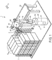
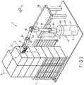
- FIG. 1 and FIG. 2 show an article holding system 1 for carrying out various types of jobs such as picking up or sorting and transfer of a wide variety of articles P (for example, unloading, loading and picking).
- the article holding system 1 comprises an article holding device 2, an article detection device 3, a robot arm 4 and a control device 5.
- the article holding device 2 is configured to hold an article P. The details of the article holding device 2 are explained later.
- the control device 5 prepares an operation plan based on data obtained from various sensors described later, and performs control based on the operation plan. For example, various sensors 13a, 19a, 19b, 20 and 23, drive shafts 17a, 17b and 21, servomotors 18a, 18b and 22, a controller 9, a recognition portion 8, the article detection device 3, a valve 13b, a compressor 13c and a vacuum generator 13d are controlled.
- the control device 5 is provided inside an arm supporting stand 4p which supports the robot arm 4.
- the article detection device 3 is configured to detect a wide variety of articles P accumulated in an accumulation area.
- articles P having a rectangular outline are shown.
- the articles are not limited to this example.
- the articles include articles P having various outline shapes such as, as shown in, for example, FIG. 6 , a spherical shape, a polygonal shape or an irregular three-dimensional shape in which both sides are curved.
- the accumulation state of articles P in the accumulation area in FIG. 1 and FIG. 2 , a plurality of articles P are orderly stacked.
- the accumulation state is not limited to this example.
- articles P may be randomly stacked.
- the holding direction for each article P is not limited to an upper direction (perpendicular direction) or a lateral direction (horizontal direction).
- a specification for holding an article in an oblique direction is also considered.
- an article container 7 is shown.
- the structure is not limited to this example.
- a desk, a conveyor belt or shelf may be provided in the accumulation area.
- a plurality of articles P may be accumulated, or a single article P may be placed.
- the RGB camera comprises three independent CCD sensors, and is configured to separately record the color signals of three colors (red, green and blue).
- the state of the articles P accumulated in the accumulation area for example, the shape, size, position, posture and distance from a 3D camera to each article P
- the state of the articles P accumulated in the accumulation area for example, the shape, size, position, posture and distance from a 3D camera to each article P
- a 3D camera and other optical sensors may be applied.
- a 3D camera When a 3D camera is applied, it is possible to separate various articles P and recognize the shape, position and posture of each of the separated articles P and the distance from the 3D camera to each article P by processing the obtained point cloud data.
- control device 5 controls the operation of the article holding device 2 and the robot arm 4 described later based on the information (for example, the state of each article P) obtained via the recognition portion 8.
- the article detection device 3 should be preferably provided such that the entire part or a part of the articles P in the accumulation area is captured within the field of view.
- the article detection device 3 may be provided in, for example, the above article container 7, the article holding device 2 or the robot arm 4 described later, or the building in which the article holding system 1 is constructed.
- the robot arm 4 comprises an attachment unit 4f to which the article holding device 2 is allowed to be attached.
- the robot arm 4 is controlled by the controller 9 (control device 5).
- controller 9 control device 5
- a 6-axis robot comprising first to sixth axes constructed on the arm supporting stand 4p is shown. The details of the attachment unit 4f are described later.
- the controller 9 controls the rotation of each axis of the robot arm (6-axis robot) 4 and transfers and rotates the attachment unit 4f in an arbitrary direction based on the result of detection (various information) of the above article detection device 3. In this way, for example, the position and posture of the article holding device 2 attached to the attachment unit 4f and the distance from the 3D camera to each article P are controlled. As a result, the article holding device 2 is allowed to approach or move away from each article P.
- controls for causing the article holding device 2 to approach and hold each article P from the upper side (perpendicular direction) as shown in FIG. 1 can be performed, or controls for causing the article holding device 2 to approach and hold each article P from a lateral side (horizontal direction) as shown in FIG. 2 can be performed.
- FIG. 4 shows a state in which an article P is held from the upper side (perpendicular direction) by the article holding device 2 (an adsorption mechanism 11 and a sandwiching mechanism 12) described later.
- FIG. 5 shows a state in which an article P is held from a lateral side (horizontal direction).
- FIG. 6 shows the holding state of an article P in which the two sides sandwiched by the sandwiching mechanism 12 described later are curved.
- the robot arm (4-axis robot) 4 comprises an arm main body 4b provided in a base 4a and rotatable around the first axis A1, a first relay arm 4c rotatable around the second axis A2 at the distal end of the arm main body 4b, a second relay arm 4d rotatable around the third axis A3 at the distal end of the first relay arm 4c, a third relay arm 4e rotatable around the fourth axis A4 at the distal end of the second relay arm 4d and the attachment unit 4f rotatable around the fifth axis A5 at the distal end of the third relay arm 4e.
- the attachment unit 4f is configured to rotate the article holding device 2 attached hereto around its sixth axis (not shown).
- the robot arm 4 is not limited to the above 6-axis robot described above.
- a 7-axis or 5- or less-axis robot, a SCARA robot or an XYZ stage may be applied.
- the robot arm 4 is secured to a certain position.
- the structure is not limited to this example.
- the robot arm 4 may be placed in a linear stage or an automated carriage so as to be movable.
- the article holding device 2 comprises a holding main body 10, the adsorption mechanism 11 and the sandwiching mechanism 12, and is configured to hold an article P which is the object to be held by adsorbing and sandwiching the article P by these elements.
- various drive shafts 17a, 17b and 21 described later and a drive force transfer mechanism (not shown) which transfers the drive force of the servomotors 18a, 18b and 22 described later to the drive shafts 17a, 17b and 21 are incorporated into the holding main body 10.
- the rectangular parallelepiped holding main body 10 is shown.
- the shape is not limited to this example.
- a shape based on the use environment and purpose such as a polygonal shape other than a rectangular parallelepiped shape or an oval shape, may be applied.
- the adsorption mechanism 11 is configured to adsorb an article P which is the object to be held.
- the adsorption mechanism 11 comprises a plurality of adsorption pads 11p which are adsorbed to a plurality of positions of an article P.
- Each absorption pad 11p is connected by piping to the vacuum system 13 shown in FIG. 13 via an air tube (not shown).
- FIG. 13 shows the pressure sensor 13a, the valve 13b, the compressor 13c and the vacuum generator 13d.
- the vacuum generator 13d is connected to each adsorption pad 11p via the pressure sensor 13a.
- the compressor 13c is connected to each adsorption pad 11p via the valve 13b.
- the valve 13b is configured to switch in three stages (first to third states).
- the compressor 13c In the third state of the valve 13b, the compressor 13c is closed. In this way, the supply of compressed air is stopped. At the time of the above switching operation of the valve 13b and the on/off operation of the vacuum generator 13d, the air pressure inside the adsorption pads 11p is measured by the pressure sensor 13a. The result of measurement is fed back to the control device 5.
- each adsorption pad 11p is vertically and horizontally arranged in a lattice shape at regular intervals such that each line has three adsorption pads 11p.
- Each adsorption pad 11p should be preferably formed of, for example, a material having less rigidity such as silicone rubber.
- each adsorption pad 11p is allowed to be deformed along the surface shape of each article P, and is also allowed to secure a certain strength for a shearing force and a moment force.
- the number of adsorption pads 11p, their sizes and arrangement are set based on, for example, the use environment and purpose of the article holding system 1 (article holding device 2). Thus, they are not particularly limited here. For example, if an article P is small, only one adsorption pad 11p may be provided.
- the arrangement of the adsorption pads 11p is not limited to the lattice shape shown in the figure.
- the adsorption pads 11p may be arranged in a staggered shape or a radial shape. Further, instead of the adsorption pads 11p, sponge pads may be applied.
- the sandwiching mechanism 12 is provided on both sides so as to sandwich the above adsorption mechanism 11, and is configured to support an adsorbed article P by sandwiching it from both sides (one side and the other side).
- the sandwiching mechanism 12 comprises sandwiching arms 14a and 14b, a sandwiching plate 15 and a link mechanism 16.
- One side and the other side of an article P have a locational relationship facing each other.
- the other side is defined on a side opposite to one side.
- a plurality of sandwiching arms 14a and 14b may be provided for the holding main body 10.
- two sandwiching arms (the first sandwiching arm 14a and the second sandwiching arm 14b) are rotatably supported in the holding main body 10.
- the sandwiching arms 14a and 14b are structured such that their proximal ends (in other words, arm rotation portions) are rotatably connected to the holding main body 10, and such that the distal end sides (in other words, arm portions) are allowed to be in contact with one side of an article P.
- the sandwiching arms 14a and 14b should be preferably structured by an elastic member such as urethane rubber or silicone rubber.
- the proximal end (arm rotation portion) of the first sandwiching arm 14a is connected to the first sandwiching arm drive axis 17a (see FIG. 13 ) incorporated into the holding main body 10.
- the first sandwiching arm drive shaft 17a is controlled by the servomotor 18a with regard to rotation.
- the torque applied to the first sandwiching arm drive shaft 17a is detected by the torque sensor 19a.
- the result of detection output from the torque sensor 19a is fed back to the control device 5. In this way, the distal end of the first sandwiching arm 14a is allowed to come into contact with one side of an article P with an optimum pressure.
- the proximal end (arm rotation portion) of the second sandwiching arm 14b is connected to the second sandwiching arm drive shaft 17b (see FIG. 13 ) incorporated into the holding main body 10.
- the second sandwiching arm drive shaft 17b is controlled by the servomotor 18b with regard to rotation.
- the torque applied to the second sandwiching arm drive shaft 17b is detected by the torque sensor 19b.
- the result of detection output from the torque sensor 19b is fed back to the control device 5. In this way, the distal end of the second sandwiching arm 14b is allowed to come into contact with one side of an article P with an optimum pressure.
- both of the sandwiching arms 14a and 14b (arm portions) have a shape curved along a direction avoiding the corner portion of an article P.
- the sandwiching arms 14a and 14b comprise a curved portion 14p curved in a direction off the straight line connecting the distal end and the proximal end.
- This curved shape is merely an example.
- the sandwiching arms 14a and 14b may be changed to an arbitrary shape (for example, a rectangle, triangle or circle) depending on the shape and size of an article P which is the object to be held.
- the curved portion 14p is located so as to be curved in a direction moving away from the sandwiching plate 15 (specifically, a contact plane 15s as described later) when the article P is held.
- the sandwiching arms 14a and 14b are allowed to come into contact with one side of the article P while the curved portion 14p does not interfere with (come into contact with) the corner portion of the article P.
- the above servomotors 18a and 18b are allowed to detect the state of rotation (for example, the amount of rotation and the rotation speed) with high accuracy in real time by their encoders.
- two sandwiching arms 14a and 14b are allowed to rotate at the same time point or different time points when the servomotors 18a and 18b, the torque sensors 19a and 19b and the control device 5 cooperate with each other. In this way, the contact pressure of the sandwiching arms 14a and 14b with regard to a wide variety of articles P can be accurately controlled.
- the sandwiching plate 15 is rotatably supported in the holding main body 10, and is configured to come into planar contact with the other side of an article P.
- the sandwiching plate 15 comprises, for example, a plate portion and a plate rotation portion.
- the plate portion comes into planar contact with the other side of an article P.
- the plate rotation portion rotatably connects the plate portion to the holding main body 10 by the link mechanism 16 (a drive link portion 16a and a following link portion 16b) described later.
- the sandwiching plate is rotatably supported in the holding main body by the plate rotation portion.
- the plate portion comes into planar contact with an article P, thereby improving the contact area of the holding main body 10 with regard to an article P.
- holding stability can be maintained so as to be constant.
- each of the bottom surface (first surface) of the holding main body 10 and the second surface of the plate portion (sandwiching plate 15) facing the bottom surface (first surface) comprises a step.
- a step surface 10s becoming hollow in a rectangular shape as compared with the other portions is structured on the bottom surface (first surface) of the holding main body 10.
- a step surface 15p and the contact plane 15s described later are structured on the second surface of the plate portion (sandwiching plate 15).
- the step surface 15p and the contact plate 15s are structured so as to have a difference in height to fit in the bottom shape (step shape) of the holding main body 10 comprising the step surface 10s.
- the step surface 15p is structured so as to protrude in a rectangular shape from the contact plane 15s.
- the step surface 15p is structured such that the link mechanism 16 (the drive link portion 16a and the following link portion 16b) are rotatably connected.
- FIG. 3 shows the sandwiching plate 15 comprising the flat contact plane 15s and the flat step surface 15p.
- the structure is not limited to this example.
- an irregular shape may be applied to a part of or the entire part of the contact plane 15s described later. By applying an irregular shape, the sandwiching performance or sandwiching stability of the contact plane 15s can be further improved.
- the sandwiching plate 15 comprises the contact plane 15s and the detection sensor 20.
- the contact plane 15s is configured to come into planar contact with the surface of the other side of an article P in parallel with the surface of the other side of the article P.
- the detection sensor 20 is provided on the contact plane 15s, and is configured to detect the contact state between the contact plane 15s and the surface of the other side of the article P.
- a commercially available contact sensor or optical sensor may be separately applied, or both of the sensors may be applied in combination.
- a contact sensor detects the contact of an article P with regard to the contact plane 15s.
- An optical sensor detects the contact of an article P with regard to the contact plane 15s by optically measuring the distance between the article P and the contact plane 15s.
- an outline shape based on the use environment and purpose such as an elliptic shape and a polygonal shape
- the sandwiching plate 15 is rotatably supported in the holding main body 10 by the link mechanism 16 described later.
- the plate rotation portion in other words, the link mechanism 16, is structured on the both sides of the above sandwiching plate 15 so as to sandwich the step surface 15p such that a pair of link portions (the drive link portion 16a and the following link portion 16b) is provided parallel to each other.
- the link portions 16a and 16b have the same outline and the same length.
- the link portions 16a and 16b have a bar-shaped outline extending straight.
- An end is rotatably connected to the sandwiching plate 15.
- the other end is rotatably connected to the holding main body 10.
- a single parallel link mechanism is structured in each of the two sides of the sandwiching plate 15.
- the parallel link mechanism includes the holding main body 10, the sandwiching plate 15 and a pair of link portions 16a and 16b. In this way, the sandwiching plate 15 is allowed to rotate toward the surface of the other side of an article P while maintaining the locational relationship parallel to the surface of the other side of the article P.
- a pair of link portions 16a and 16b the other end of one link portion (in other words, the drive link portion 16a) is connected to the parallel link drive shaft 21 (see FIG. 13 ) incorporated into the holding main body 10, and the parallel link drive shaft 21 is controlled by the servomotor 22 with regard to rotation.
- the other end of the other link portion in other words, the following link portion 16b is rotatably supported in the holding main body 10.
- the above servomotor 22 is allowed to detect the state of rotation (for example, the amount of rotation and the rotation speed) with high accuracy in real time by its encoder.
- the above sandwiching plate 15 is allowed to rotate at an optimum time point when the servomotor 22, the torque sensor 23 and the control device 5 cooperate with each other. In this way, the contact pressure of the sandwiching plate 15 (contact plane 15s) with regard to a wide variety of articles P can be accurately controlled.
- the inside of the article container 7 provided in the accumulation area is captured by the article detection device 3 (S1 in FIG. 14 ).
- image data is output from the article detection device 3, and the recognition portion 8 applies image processing to the image data (S2 in FIG. 14 ).
- the recognition portion 8 applies image processing to the image data (S2 in FIG. 14 ). In this way, for example, the presence or absence of an article P inside the article container 7 and the state of accommodation of articles P (the stacked form or angle) are detected.
- control device 5 finishes image processing based on an output signal from the recognition portion 8.
- the recognition portion 8 separately cuts the articles P included in the image data (S4 in FIG. 14 ) and selects one of the cut articles P based on the criterion set in advance (S5 in FIG. 14 ). Thus, the object to be held is specified.
- the criterion set in advance is not particularly limited.
- the object provided at the highest position, the object located in front of the robot arm 4, an object having a sufficient gap with the other articles P, an object close to the center of the article container 7 or an object defined in advance on database such that it is easily held is assumed.
- image processing is applied again in the recognition portion 8, thereby recognizing the state of the specified article P (the object to be held) (S6 in FIG. 14 ).
- the state of the article for example, the shape, size, position and posture of the article P and the distance from the 3D camera to the article P are assumed.
- the recognition portion 8 transmits data related to the state of the specified article P to the control device 5.
- the control device 5 plans the operation of the robot arm 4 and the article holding device 2 based on the data and performs control.
- the determination criterion for example, the degree of unevenness of the surface of the article or the curvature is assumed.
- the determination method when a plane which can be adsorbed to all the adsorption pads 11p is present on the upper surface or a side surface of the article P, it is determined that the article P can be adsorbed. When a plane is not present, it is determined that the article P cannot be adsorbed.
- the control device 5 determines whether or not the specified article P can be adsorbed and held from the upper side (perpendicular direction) of the article P (S8 in FIG. 14 ). At this time, when a surface which can be adsorbed is present on the upper side (perpendicular direction) as shown in FIG. 1 , the control device 5 plans and performs controls for adsorbing and holding the article P from the upper surface (S9 in FIG. 14 ).
- the control device 5 plans and performs controls for adsorbing and holding the article P from the lateral side (S10 in FIG. 14 ).
- the operation of processes S9 to S10 (operation for adsorbing and holding the upper surface and operation for adsorbing and holding a side surface) is described later with reference to FIG. 15 and FIG. 16 .
- control device 5 plans and performs controls for holding the article P by sandwiching the article P without performing adsorption operation (S11 in FIG. 14 ).
- the control device 5 performs the control of the robot arm 4 (S12 in FIG. 14 ).
- the article P held by the article holding device 2 is transferred from the article container 7 to a belt conveyor 24 while following the operation of the robot arm 4 as shown in, for example, FIG. 1 and FIG. 2 .
- control device 5 plans and performs controls for releasing the article P to the belt conveyor 24 (S13 in FIG. 14 ).
- the release operation of process S13 is described later (see FIG. 17 ).
- the control device 5 causes the article holding device 2 to return to the initial state (S14 in FIG. 14 ).
- the initial state for example, as shown in FIG. 1 , FIG. 2 , FIG. 7 and FIG. 8 , a state in which the sandwiching arms 14a and 14b and the sandwiching plate 15 are stored along the holding main body 10 is assumed.
- control device 5 controls the operation of the robot arm 4 (S9-1 in FIG. 15 ). At this time, as shown in FIG. 1 , controls for causing the article holding device 2 to approach and hold each article P provided inside the article container 7 from the upper side (perpendicular direction) are performed.
- control device 5 controls the article holding device 2 so as to be in the holding waiting posture as shown in FIG. 3 (S9-2 in S15).
- the parallel link mechanism (the holding main body 10, the sandwiching plate 15, a pair of link portions 16a and 16b) and two sandwiching arms 14a and 14b are displaced.
- a pair of link portions 16a and 16b is developed to the lower side in a perpendicular direction, and both of the sandwiching arms 14a and 14b are developed to the upper side in a perpendicular direction.
- the article holding device 2 in other words, the adsorption mechanism 11
- the adsorption mechanism 11 is allowed to approach the specified article P (the object to be held) and adsorb the article P without coming into contact with the article container 7 or the other articles P.
- the control device 5 switches the valve 13b of the vacuum system 13 of FIG. 13 to the first state (S9-3 in FIG. 15 ).
- the first state of the valve compressed air is supplied from the compressor 13c to the vacuum generator 13d.
- a negative pressure is applied to the adsorption pads 11p.
- the upper surface of the article can be adsorbed to the adsorption pads 11p.
- control device 5 controls the operation of the robot arm 4 so as to cause the sandwiching plate 15 (in other words, the contact plane 15s) to approach the specified article P while monitoring the output of the above detection sensor 20 (S9-4 in FIG. 15 ).
- the output of the detection sensor 20 is in an on-state (contact state) (S9-5 in FIG. 15 )
- the operation of the robot arm 4 is stopped.
- control device 5 controls the operation of the robot arm 4 so as to cause the adsorption mechanism 11 (in other words, the adsorption pads 11p) to come into contact with the specified article P while monitoring the output of the pressure sensor 13a of the vacuum system 13 of FIG. 13 (S9-6 in FIG. 15 ).
- the control device 5 determines that the specified article P is adsorbed to the adsorption pads 11p by an optimum pressure (adsorption pressure).
- the control device 5 controls the servomotors 18a, 18b and 22 and operates various drive shafts 17a, 17b and 21 (S9-8 in FIG. 15 ). In this way, both sides of the specified article P are sandwiched by the sandwiching mechanism 12 (the sandwiching arms 14a and 14b and the sandwiching plate 15).
- the control device 5 checks the output of the torque sensors 19a, 19b and 23 (S9-9 in FIG. 15 ) and controls the servomotors 18a, 18b and 22 until the output value exceeds a threshold set in advance (S9-10 to S9-11 in FIG. 15 ).
- a threshold set in advance S9-10 to S9-11 in FIG. 15 .
- the control device 5 controls the operation of the robot arm 4 (S10-1 in FIG. 16 ). At this time, as shown in FIG. 2 , controls for causing the article holding device 2 to approach and hold each article P provided inside the article container 7 from a lateral side (horizontal direction) are performed. In this period, the article holding device 2 is maintained so as to be in the initial state as shown in, for example, FIG. 1 , FIG. 2 , FIG. 7 and FIG. 8 .
- control device 5 causes the article holding device 2 (in other words, the adsorption mechanism 11) to approach a side surface (see FIG. 7 ) of the specified article P (the object to be held) and adsorb the article P (S10-3 in FIG. 16 ) while controlling the article holding device 2 so as to be in the initial state (S10-2 in FIG. 16 ).
- the control device 5 determines that the specified article P is adsorbed to the adsorption pads 11p.
- the control device 5 controls the operation of the robot arm 4 so as to draw the article P as shown in FIG. 8 (S10-5 in FIG. 16 ).
- a specification for drawing the specified article P toward the robot arm 4 by only a distance set in advance can be assumed. In this case, the drawing distance of the article P is set to an extent that the drawn article P does not fall.
- the size or depth of the specified article P is clear when the article P is drawn, setting is performed based on the size and depth.
- the size and depth of the article P may be obtained from the result of processing in the recognition portion 8, or may be obtained by referring to database in which the information of the article P is registered in advance.
- the article P When, for example, the size or depth of the article P is not clear in advance, the article P may fall. In particular, in a state where a plurality of articles P are orderly stacked, the depth of each article P may be difficult to know.
- an article P is firstly drawn by only a short distance. Subsequently, a process for reviewing the article P is performed. In this way, a gap is formed between the articles.
- the size and depth of each article P can be accurately recognized.
- the article P can be drawn by only a distance set in advance without falling.
- the distance set in advance may be, for example, a distance equivalent to 30% of the depth of the recognized article P.
- the control device 5 switches the valve 13b (see FIG. 13 ) of the vacuum system 13 to the second state (S10-6 in FIG. 16 ).
- the second state of the valve 13b compressed air is directly supplied from the compressor 13c to the adsorption pads 11p.
- the adsorption pads 11p are returned to a barometric pressure state.
- the adsorption state of the adsorption pads 11p with regard to the article P is cancelled.
- control device 5 controls the operation of the robot arm 4 such that the article holding device 2 moves away (goes back) from the article P (S10-7 in FIG. 16 ). Subsequently, the control device 5 controls the article holding device 2 so as to be in a holding waiting posture (see FIG. 3 ) (S10-8 in FIG. 16 ).
- the control device 5 switches the valve 13b (see FIG. 13 ) of the vacuum system 13 to the above first state (S10-9 in FIG. 16 ). Subsequently, the control device 5 controls the operation of the robot arm 4 so as to cause the sandwiching plate 15 (contact plane 15s) to approach the specified article P while monitoring the output of the above detection sensor 20 (S10-10 in FIG. 16 ). When the output of the detection sensor 20 is in an on-state (contact state) (S10-11 in FIG. 16 ), the operation of the robot arm 4 is stopped as shown in, for example, FIG. 9 .
- control device 5 controls the operation of the robot arm 4 so as to cause the adsorption mechanism 11 (adsorption pads 11p) to approach the specified article P while monitoring the output of the pressure sensor 13a of the vacuum system 13 of FIG. 13 (S10-12 in FIG. 16 ).
- the control device 5 determines that the specified article P is adsorbed to the adsorption pads 11p.
- the control device 5 controls the servomotors 18a, 18b and 22 and operates various drive shafts 17a, 17b and 21 (S10-14 in FIG. 16 ). In this way, both sides of the specified article P are sandwiched by the sandwiching mechanism 12 (the sandwiching arms 14a and 14b and the sandwiching plate 15) (see FIG. 10 ).
- the control device 5 checks the output of the torque sensors 19a, 19b and 23 (S10-15 in FIG. 16 ) and controls the servomotors 18a, 18b and 22 until the output value exceeds a threshold set in advance (S10-16 to S10-17 in FIG. 16 ).
- a threshold set in advance S10-16 to S10-17 in FIG. 16 .
- the article P When either the operation for adsorbing and holding the upper surface or the operation for adsorbing and holding a side surface is applied, the article P is in a state where both sides are sandwiched by the sandwiching mechanism 12 as the portion adsorbed by the adsorption mechanism 11 is sandwiched (in other words, an adsorption holding state). While maintaining the adsorption holding state, for example, as shown in FIG. 11 and FIG. 12 , the article P is transferred from the article container 7 to the belt conveyor 24.
- the control device 5 plans and performs controls for releasing the article P to the belt conveyor 24. Firstly, the control device 5 drives the servomotors 18a, 18b and 22, thereby cancelling the sandwiching state by the sandwiching mechanism 12 (the sandwiching arms 14a and 14b and the sandwiching plate 15) (S13-1 in FIG. 17 ).
- control device 5 switches the valve 13b of the vacuum system 13 of FIG. 13 to the second state (S13-2 in FIG. 17 ), and cancels the adsorption state of the adsorption pads 11p with regard to the article P.
- the control device 5 determines that the article P is not removed from the adsorption pads 11p and displaces the sandwiching mechanism 12 by driving the servomotors 18a, 18b and 22 (S13-4 in FIG. 17 ).
- the sandwiching arms 14a and 14b or the sandwiching plate 15 are/is developed toward the article P.
- the article P is pushed out in a direction moving away from the adsorption pads 11p. In this way, the article P can be removed from the adsorption pads 11p. As a result, the article P can be transferred to the belt conveyor 24.
- the control device 5 determines that the article P is removed from the adsorption pads 11p. At this time, the article P is transferred to the belt conveyor 24.
- control device 5 controls the operation of the robot arm 4 such that the article holding device 2 is moved away from the article P (S13-5 in FIG. 17 ). Thus, release operation is completed.
- the sandwiching mechanism 12 comprises the sandwiching arms 14a and 14b which are allowed to come into contact with one side of the article P, and the board-like sandwiching plate 15 which is allowed to come into planar contact with the other side of the article P.
- a contact area with regard to the article P which is the object to be held can be increased while maintaining the followingness and responsiveness for holding operation so as to be constant. As a result, the article P can be stably held.
- each article P can be held from a lateral side (horizontal direction) as well as the upper side (perpendicular direction).
- the zippy article holding system 1 can be constructed. Specifically, when a job for unloading articles P stacked high is assumed, there is no need to use a long robot arm. A smaller system (in other words, a low-cost system which can be easily installed) can be realized. Further, holding in view of subsequent steps is allowed by expanding the holding direction. For example, in loading, articles P can be loaded while changing the posture of each article P.
- each article P is held by the adsorption force F11 of the adsorption mechanism 11 and the sandwiching force F12 of the sandwiching mechanism 12 until the article P is transferred from the article container 7 to the belt conveyor 24.
- the sandwiching plate 15 and the link portions 16a and 16b are maintained so as to have a locational relationship orthogonal to each other.
- the perpendicular reaction applied to the sandwiching plate 15 has resistance by the rigidity of the above parallel link mechanism.
- a moment load MG based on the distal end of the sandwiching plate 15 is applied to the parallel link mechanism.
- the moment load MG can be dealt with by the adsorption force F11 of the adsorption mechanism 11.
- intersection angle between the sandwiching plate 15 and the link portions 16a and 16b is less than or equal to 90°, the contact area between the sandwiching plate 15 and the article P is less.
- This state has an advantage in which a surrounding obstacle can be easily avoided.
- this state is disadvantageous in terms of the stability of a holding state.
- the intersection angle between the sandwiching plate 15 and the link portions 16a and 16b should be preferably set to 90°.
- the intersection angle may be changed to, for example, 70° to 90°.
- the contact plane 15s and the step surface 15p are structured on the sandwiching plate 15 so as to fit in the step shape of the bottom surface 10s of the holding main body 10.
- the sandwiching plate 15 is allowed to slide into an article P without restricting the movement of the link portions 16a and 16b.
- the contact area of the holding main body 10 with regard to an article P is improved, thereby maintaining constant sandwiching stability.
- the first sandwiching arm 14a and the second sandwiching arm 14b are driven by the servomotors 18a and 18b, respectively.
- the drive shafts 17a and 17b of both of the sandwiching arms 14a and 14b may be commonized. In this way, the number of servomotors can be decreased. As a result, both the cost and the weight of the article holding device 2 can be reduced at the same time.
- both of the sandwiching arms 14a and 14b have a structure which is not free excluding the drive shafts 17a and 17b.
- one of or both of the sandwiching arms 14a and 14b may be divided into two.
- an underactuated shaft which operates by following drive via a wire pulley mechanism or a belt pulley mechanism from the drive shafts 17a and 17b may be provided.
- the degree of freedom of the track drawn by the distal end (finger point) of each of the sandwiching arms 14a and 14b can be improved.
- the sandwiching mechanism 12 (the sandwiching arms 14a and 14b and the sandwiching plate 15) and the parallel link mechanism are driven by using the servomotors 18a, 18b and 22.
- a linear motor, a ball screw, a DC motor or a brushless DC motor may be used.
- the encoders may be attached to the outside.
- vacuum supply may be applied to the adsorption pads 11p via a plurality of pipe systems, or vacuum supply may be applied to the adsorption pads 11p from a single pipe system.
- a throttle valve may be provided on the upstream of the adsorption pads 11p, thereby controlling the change of the flow rate. In this way, the air leak from the released adsorption pads 11p can be reduced. Even when a small article P or an article in which the curvature of the adsorption surface is great is adsorbed and held, a high vacuum pressure can be maintained.
- a throttle valve may be provided in all the adsorption pads 11p, or may be provided in some of them. For example, when a structure in which a throttle valve is provided only around a plurality of adsorption pads 11p is assumed, the vacuum pressure of the central portion can be maintained so as to be constant, and the air leak from the surrounding adsorption pads 11p can be decreased. As a result, an article P can be stably adsorbed.
- the pressure sensor 13a is used to detect the state of adsorption of the adsorption mechanism 11 (adsorption pads 11p).
- a flow rate sensor may be used, or both a pressure sensor and a flow rate sensor may be used.
- another optical sensor may be combined.
- an optical sensor may be attached to the holding main body 10 to measure the distance to an article P in an adsorption direction. Based on the measured distance, whether or not the adsorption pads 11p are less than or equal to an equilibrium length is determined to detect the state of adsorption.
- the three processes of upper-surface adsorption holding, a side-surface adsorption holding and sandwiching holding are shown.
- other holding specifications may be applied to the holding technology of the present invention.
- the adsorption mechanism 11 may be used for holding. While adsorbing an article P by the adsorption mechanism 11, the article P may be sandwiched by the parallel link mechanism and the sandwiching arms 14a and 14b in which the intersection angle is greater than or equal to 90°.
Landscapes
- Engineering & Computer Science (AREA)
- Mechanical Engineering (AREA)
- Robotics (AREA)
- Human Computer Interaction (AREA)
- Health & Medical Sciences (AREA)
- General Health & Medical Sciences (AREA)
- Orthopedic Medicine & Surgery (AREA)
- Manipulator (AREA)
Abstract
Description
- Embodiments of the present invention relate generally to a holding technology for holding an article which is the object to be held.
- Currently, for example, in the lines of distribution warehouses and plants, various types of jobs such as picking up or sorting and transfer of various articles are carried out by an article holding device attached to the distal end of a robot arm instead of manpower. In this case, the article holding device comprises an adsorption mechanism which adsorbs an article and can support the article, and a sandwiching mechanism which sandwiches the adsorbed article from both sides and can support the article. In this structure, the sandwiching mechanism comprises a plurality of sandwiching arms comprising a sandwiching function. Each of the sandwiching arms has an outline shape similar to a finger (nail) of a human.
-
- Patent Literature 1:
JP H08-318488 A - Patent Literature 2:
JP 4708464 B - Patent Literature 3:
JP 2014-144526 A - In the above sandwiching arms, as a contact area with respect to an article is small (in other words, there is a limit to an increase in a contact area), it may be difficult to stably support the article depending on the type of the article (for example, the outline shape and weight). In this case, the contact area of each sandwiching arm with respect to the article could be increased. However, if the contact area is increased, the sandwiching arm itself is upsized and becomes heavy. As a result, it may be difficult to maintain constant followingness and responsiveness for sandwiching operation.
- An object of the present invention is to provide a holding technology whereby an article which is the object to be held can be stably held by increasing a contact area with respect to the article.
- According to an embodiment, a holding main body, an adsorption mechanism and a sandwiching mechanism are provided. The sandwiching mechanism comprises a sandwiching arm which comes into contact with one side of an article, and a board-like sandwiching plate which comes into planar contact with the other side of the article.
-
-
FIG. 1 is a perspective view showing a specification (upper-surface adsorption holding) state of an article holding system according to an embodiment. -
FIG. 2 is a perspective view showing a specification state (side-surface adsorption holding) of the article holding system according to the embodiment. -
FIG. 3 is a perspective view of an article holding device applied to the article holding system. -
FIG. 4 is a perspective view of the article holding device in an upper-surface adsorption holding state. -
FIG. 5 is a perspective view of the article holding device in a side-surface adsorption holding state. -
FIG. 6 is a perspective view showing the holding state of an article having the outline of a curved surface. -
FIG. 7 is a perspective view showing an adsorption process. -
FIG. 8 is a perspective view showing the drawing process of an adsorbed article. -
FIG. 9 is a perspective view showing the developing process of a holding mechanism. -
FIG. 10 is a perspective view showing a holding process. -
FIG. 11 is a side view showing a state in which a force is applied in a side-surface adsorption holding state. -
FIG. 12 is a side view showing a state in which a force is applied in an upper-surface adsorption holding state. -
FIG. 13 is a block diagram of a control circuit applied to the article holding system. -
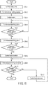
FIG. 14 is a flowchart showing the operation of the article holding system. -
FIG. 15 is a flowchart for performing upper-surface adsorption holding. -
FIG. 16 is a flowchart for performing side-surface adsorption holding. -
FIG. 17 is a flowchart for releasing an article which is adsorbed and held. - Mode for Carrying Out the Invention Hereinafter, this specification explains an article holding system according to an embodiment of the present invention.
-
FIG. 1 andFIG. 2 show anarticle holding system 1 for carrying out various types of jobs such as picking up or sorting and transfer of a wide variety of articles P (for example, unloading, loading and picking). Thearticle holding system 1 comprises anarticle holding device 2, anarticle detection device 3, arobot arm 4 and acontrol device 5. - The
article holding device 2 is configured to hold an article P. The details of thearticle holding device 2 are explained later. Thecontrol device 5 prepares an operation plan based on data obtained from various sensors described later, and performs control based on the operation plan. For example,various sensors drive shafts servomotors controller 9, a recognition portion 8, thearticle detection device 3, avalve 13b, acompressor 13c and avacuum generator 13d are controlled. Thecontrol device 5 is provided inside an arm supporting stand 4p which supports therobot arm 4. - The
article detection device 3 is configured to detect a wide variety of articles P accumulated in an accumulation area. InFIG. 1 andFIG. 2 , as an example, articles P having a rectangular outline are shown. However, the articles are not limited to this example. The articles include articles P having various outline shapes such as, as shown in, for example,FIG. 6 , a spherical shape, a polygonal shape or an irregular three-dimensional shape in which both sides are curved. - As the accumulation state of articles P in the accumulation area, in
FIG. 1 andFIG. 2 , a plurality of articles P are orderly stacked. However, the accumulation state is not limited to this example. For example, articles P may be randomly stacked. When articles P are randomly stacked, the holding direction for each article P is not limited to an upper direction (perpendicular direction) or a lateral direction (horizontal direction). A specification for holding an article in an oblique direction is also considered. - As the structure of the accumulation area, in
FIG. 1 andFIG. 2 , anarticle container 7 is shown. However, the structure is not limited to this example. For example, a desk, a conveyor belt or shelf may be provided in the accumulation area. In the accumulation area, a plurality of articles P may be accumulated, or a single article P may be placed. - For the
article detection device 3, for example, a commercially available RGB camera may be applied. The RGB camera comprises three independent CCD sensors, and is configured to separately record the color signals of three colors (red, green and blue). In this way, the state of the articles P accumulated in the accumulation area (for example, the shape, size, position, posture and distance from a 3D camera to each article P) can be detected with high accuracy. - For the
article detection device 3, other than the above RGB camera, for example, a 3D camera and other optical sensors may be applied. When a 3D camera is applied, it is possible to separate various articles P and recognize the shape, position and posture of each of the separated articles P and the distance from the 3D camera to each article P by processing the obtained point cloud data. - Various types of information (for example, the result of detection such as the state of each article P described above) detected by the
article detection device 3 undergo image processing in the recognition portion 8 and are transmitted to thecontrol device 5 described later. In this case, for the recognition portion 8, for example, a commercially available computer may be applied. Thecontrol device 5 controls the operation of thearticle holding device 2 and therobot arm 4 described later based on the information (for example, the state of each article P) obtained via the recognition portion 8. - The
article detection device 3 should be preferably provided such that the entire part or a part of the articles P in the accumulation area is captured within the field of view. In this case, thearticle detection device 3 may be provided in, for example, theabove article container 7, thearticle holding device 2 or therobot arm 4 described later, or the building in which thearticle holding system 1 is constructed. - The
robot arm 4 comprises anattachment unit 4f to which thearticle holding device 2 is allowed to be attached. Therobot arm 4 is controlled by the controller 9 (control device 5). In the figures, as an example of therobot arm 4, a 6-axis robot comprising first to sixth axes constructed on the arm supporting stand 4p is shown. The details of theattachment unit 4f are described later. - In this case, the
controller 9 controls the rotation of each axis of the robot arm (6-axis robot) 4 and transfers and rotates theattachment unit 4f in an arbitrary direction based on the result of detection (various information) of the abovearticle detection device 3. In this way, for example, the position and posture of thearticle holding device 2 attached to theattachment unit 4f and the distance from the 3D camera to each article P are controlled. As a result, thearticle holding device 2 is allowed to approach or move away from each article P. - Thus, with respect to each article P accumulated in the accumulation area, controls for causing the
article holding device 2 to approach and hold each article P from the upper side (perpendicular direction) as shown inFIG. 1 can be performed, or controls for causing thearticle holding device 2 to approach and hold each article P from a lateral side (horizontal direction) as shown inFIG. 2 can be performed. - For example,
FIG. 4 shows a state in which an article P is held from the upper side (perpendicular direction) by the article holding device 2 (anadsorption mechanism 11 and a sandwiching mechanism 12) described later.FIG. 5 shows a state in which an article P is held from a lateral side (horizontal direction).FIG. 6 shows the holding state of an article P in which the two sides sandwiched by thesandwiching mechanism 12 described later are curved. - As shown in
FIG. 1 andFIG. 2 , the robot arm (6-axis robot) 4 comprises an armmain body 4b provided in abase 4a and rotatable around the first axis A1, a first relay arm 4c rotatable around the second axis A2 at the distal end of the armmain body 4b, asecond relay arm 4d rotatable around the third axis A3 at the distal end of the first relay arm 4c, athird relay arm 4e rotatable around the fourth axis A4 at the distal end of thesecond relay arm 4d and theattachment unit 4f rotatable around the fifth axis A5 at the distal end of thethird relay arm 4e. Theattachment unit 4f is configured to rotate thearticle holding device 2 attached hereto around its sixth axis (not shown). - The
robot arm 4 is not limited to the above 6-axis robot described above. For example, a 7-axis or 5- or less-axis robot, a SCARA robot or an XYZ stage may be applied. InFIG. 1 andFIG. 2 , as an example, therobot arm 4 is secured to a certain position. However, the structure is not limited to this example. For example, therobot arm 4 may be placed in a linear stage or an automated carriage so as to be movable. - As shown in
FIG. 1 to FIG. 6 , thearticle holding device 2 comprises a holdingmain body 10, theadsorption mechanism 11 and thesandwiching mechanism 12, and is configured to hold an article P which is the object to be held by adsorbing and sandwiching the article P by these elements. - For example,
various drive shafts servomotors drive shafts main body 10. - In
FIG. 1 to FIG. 6 , as an example, the rectangular parallelepiped holdingmain body 10 is shown. However, the shape is not limited to this example. For example, a shape based on the use environment and purpose, such as a polygonal shape other than a rectangular parallelepiped shape or an oval shape, may be applied. - The
adsorption mechanism 11 is configured to adsorb an article P which is the object to be held. Theadsorption mechanism 11 comprises a plurality ofadsorption pads 11p which are adsorbed to a plurality of positions of an article P. Eachabsorption pad 11p is connected by piping to thevacuum system 13 shown inFIG. 13 via an air tube (not shown). As an example of the vacuum system,FIG. 13 shows thepressure sensor 13a, thevalve 13b, thecompressor 13c and thevacuum generator 13d. Thevacuum generator 13d is connected to eachadsorption pad 11p via thepressure sensor 13a. Further, thecompressor 13c is connected to eachadsorption pad 11p via thevalve 13b. For example, thevalve 13b is configured to switch in three stages (first to third states). - In this structure, in the first state of the
valve 13b, compressed air is supplied from thecompressor 13c to thevacuum generator 13d. In this way, an article P which comes into contact with the adsorption mechanism 11 (adsorption pads 11p) can be adsorbed to the adsorption mechanism 11 (adsorption pads 11p) by a negative pressure. - In the second state of the
valve 13b, compressed air is directly supplied from thecompressor 13c to theadsorption pads 11p. In this way, the vacuum of theadsorption pads 11p is broken, thereby becoming barometric pressure. Thus, an article P can be released from the adsorption mechanism 11 (adsorption pads 11p). - In the third state of the
valve 13b, thecompressor 13c is closed. In this way, the supply of compressed air is stopped. At the time of the above switching operation of thevalve 13b and the on/off operation of thevacuum generator 13d, the air pressure inside theadsorption pads 11p is measured by thepressure sensor 13a. The result of measurement is fed back to thecontrol device 5. - In
FIG. 3 , as an example, nineadsorption pads 11p are vertically and horizontally arranged in a lattice shape at regular intervals such that each line has threeadsorption pads 11p. Eachadsorption pad 11p should be preferably formed of, for example, a material having less rigidity such as silicone rubber. In this structure, eachadsorption pad 11p is allowed to be deformed along the surface shape of each article P, and is also allowed to secure a certain strength for a shearing force and a moment force. - The number of
adsorption pads 11p, their sizes and arrangement are set based on, for example, the use environment and purpose of the article holding system 1 (article holding device 2). Thus, they are not particularly limited here. For example, if an article P is small, only oneadsorption pad 11p may be provided. The arrangement of theadsorption pads 11p is not limited to the lattice shape shown in the figure. Theadsorption pads 11p may be arranged in a staggered shape or a radial shape. Further, instead of theadsorption pads 11p, sponge pads may be applied. - The
sandwiching mechanism 12 is provided on both sides so as to sandwich theabove adsorption mechanism 11, and is configured to support an adsorbed article P by sandwiching it from both sides (one side and the other side). To realize this structure, thesandwiching mechanism 12 comprises sandwichingarms plate 15 and a link mechanism 16. One side and the other side of an article P have a locational relationship facing each other. The other side is defined on a side opposite to one side. - As shown in
FIG. 3 to FIG. 6 , a plurality of sandwichingarms main body 10. InFIG. 3 to FIG. 6 , as an example, two sandwiching arms (thefirst sandwiching arm 14a and thesecond sandwiching arm 14b) are rotatably supported in the holdingmain body 10. The sandwichingarms main body 10, and such that the distal end sides (in other words, arm portions) are allowed to be in contact with one side of an article P. In this case, the sandwichingarms - The proximal end (arm rotation portion) of the
first sandwiching arm 14a is connected to the first sandwichingarm drive axis 17a (seeFIG. 13 ) incorporated into the holdingmain body 10. The first sandwichingarm drive shaft 17a is controlled by theservomotor 18a with regard to rotation. In this case, at the time of rotation control by theservomotor 18a, the torque applied to the first sandwichingarm drive shaft 17a is detected by thetorque sensor 19a. At this time, the result of detection output from thetorque sensor 19a is fed back to thecontrol device 5. In this way, the distal end of thefirst sandwiching arm 14a is allowed to come into contact with one side of an article P with an optimum pressure. - The proximal end (arm rotation portion) of the
second sandwiching arm 14b is connected to the second sandwichingarm drive shaft 17b (seeFIG. 13 ) incorporated into the holdingmain body 10. The second sandwichingarm drive shaft 17b is controlled by theservomotor 18b with regard to rotation. In this case, at the time of rotation control by theservomotor 18b, the torque applied to the second sandwichingarm drive shaft 17b is detected by thetorque sensor 19b. At this time, the result of detection output from thetorque sensor 19b is fed back to thecontrol device 5. In this way, the distal end of thesecond sandwiching arm 14b is allowed to come into contact with one side of an article P with an optimum pressure. - Further, both of the sandwiching
arms arms curved portion 14p curved in a direction off the straight line connecting the distal end and the proximal end. This curved shape is merely an example. The sandwichingarms - In this case, in the process of holding an article between the sandwiching
arms plate 15 described later, thecurved portion 14p is located so as to be curved in a direction moving away from the sandwiching plate 15 (specifically, acontact plane 15s as described later) when the article P is held. In this way, the sandwichingarms curved portion 14p does not interfere with (come into contact with) the corner portion of the article P. - The
above servomotors arms servomotors torque sensors control device 5 cooperate with each other. In this way, the contact pressure of the sandwichingarms - As shown in
FIG. 3 to FIG. 6 , the sandwichingplate 15 is rotatably supported in the holdingmain body 10, and is configured to come into planar contact with the other side of an article P. In this case, the sandwichingplate 15 comprises, for example, a plate portion and a plate rotation portion. The plate portion comes into planar contact with the other side of an article P. The plate rotation portion rotatably connects the plate portion to the holdingmain body 10 by the link mechanism 16 (adrive link portion 16a and a followinglink portion 16b) described later. Thus, the sandwiching plate is rotatably supported in the holding main body by the plate rotation portion. In this structure, the plate portion (sandwiching plate 15) comes into planar contact with an article P, thereby improving the contact area of the holdingmain body 10 with regard to an article P. As a result, holding stability can be maintained so as to be constant. - Further, each of the bottom surface (first surface) of the holding
main body 10 and the second surface of the plate portion (sandwiching plate 15) facing the bottom surface (first surface) comprises a step. In this case, astep surface 10s becoming hollow in a rectangular shape as compared with the other portions is structured on the bottom surface (first surface) of the holdingmain body 10. On the second surface of the plate portion (sandwiching plate 15), astep surface 15p and thecontact plane 15s described later are structured. Thestep surface 15p and thecontact plate 15s are structured so as to have a difference in height to fit in the bottom shape (step shape) of the holdingmain body 10 comprising thestep surface 10s. Thestep surface 15p is structured so as to protrude in a rectangular shape from thecontact plane 15s. Thestep surface 15p is structured such that the link mechanism 16 (thedrive link portion 16a and thefollowing link portion 16b) are rotatably connected. - As an example,
FIG. 3 shows the sandwichingplate 15 comprising theflat contact plane 15s and theflat step surface 15p. However, the structure is not limited to this example. For example, an irregular shape may be applied to a part of or the entire part of thecontact plane 15s described later. By applying an irregular shape, the sandwiching performance or sandwiching stability of thecontact plane 15s can be further improved. - The sandwiching
plate 15 comprises thecontact plane 15s and thedetection sensor 20. Thecontact plane 15s is configured to come into planar contact with the surface of the other side of an article P in parallel with the surface of the other side of the article P. Thedetection sensor 20 is provided on thecontact plane 15s, and is configured to detect the contact state between thecontact plane 15s and the surface of the other side of the article P. - For the
detection sensor 20, for example, a commercially available contact sensor or optical sensor may be separately applied, or both of the sensors may be applied in combination. A contact sensor detects the contact of an article P with regard to thecontact plane 15s. An optical sensor detects the contact of an article P with regard to thecontact plane 15s by optically measuring the distance between the article P and thecontact plane 15s. - For the outline shape of the sandwiching
plate 15, instead of a rectangular board-like shape, for example, an outline shape based on the use environment and purpose, such as an elliptic shape and a polygonal shape, may be applied. In this case, even if any outline shape is applied, the sandwichingplate 15 is rotatably supported in the holdingmain body 10 by the link mechanism 16 described later. - As shown in
FIG. 3 to FIG. 6 , the plate rotation portion, in other words, the link mechanism 16, is structured on the both sides of theabove sandwiching plate 15 so as to sandwich thestep surface 15p such that a pair of link portions (thedrive link portion 16a and thefollowing link portion 16b) is provided parallel to each other. Thelink portions FIG. 3 to FIG. 6 , as an example, thelink portions sandwiching plate 15. The other end is rotatably connected to the holdingmain body 10. - Further, a single parallel link mechanism is structured in each of the two sides of the sandwiching
plate 15. The parallel link mechanism includes the holdingmain body 10, the sandwichingplate 15 and a pair oflink portions plate 15 is allowed to rotate toward the surface of the other side of an article P while maintaining the locational relationship parallel to the surface of the other side of the article P. - In a pair of
link portions drive link portion 16a) is connected to the parallel link drive shaft 21 (seeFIG. 13 ) incorporated into the holdingmain body 10, and the parallellink drive shaft 21 is controlled by theservomotor 22 with regard to rotation. In a pair oflink portions link portion 16b) is rotatably supported in the holdingmain body 10. - In this case, at the time of rotation control by the
servomotor 22, the torque applied to the parallellink drive shaft 21 is detected by thetorque sensor 23. At this time, the result of detection output from thetorque sensor 23 is fed back to thecontrol device 5. In this way, thedrive link portion 16a rotates around its other end. By following this rotation, the sandwichingplate 15 and thefollowing link portion 16b rotate. As a result, the sandwiching plate 15 (contact plane 15s) is allowed to approach the surface of the other side of an article P in parallel. - The
above servomotor 22 is allowed to detect the state of rotation (for example, the amount of rotation and the rotation speed) with high accuracy in real time by its encoder. In this case, theabove sandwiching plate 15 is allowed to rotate at an optimum time point when theservomotor 22, thetorque sensor 23 and thecontrol device 5 cooperate with each other. In this way, the contact pressure of the sandwiching plate 15 (contact plane 15s) with regard to a wide variety of articles P can be accurately controlled. - Now, this specification explains the main operation of the
article holding system 1 with reference toFIG. 14 to FIG. 17 . - The inside of the
article container 7 provided in the accumulation area is captured by the article detection device 3 (S1 inFIG. 14 ). At this time, image data is output from thearticle detection device 3, and the recognition portion 8 applies image processing to the image data (S2 inFIG. 14 ). In this way, for example, the presence or absence of an article P inside thearticle container 7 and the state of accommodation of articles P (the stacked form or angle) are detected. - When no article P is present inside the article container 7 (S3 in
FIG. 14 ), thecontrol device 5 finishes image processing based on an output signal from the recognition portion 8. - When articles P are present inside the article container 7 (S3 in
FIG. 14 ), the recognition portion 8 separately cuts the articles P included in the image data (S4 inFIG. 14 ) and selects one of the cut articles P based on the criterion set in advance (S5 inFIG. 14 ). Thus, the object to be held is specified. - The criterion set in advance is not particularly limited. For example, as the criterion, the object provided at the highest position, the object located in front of the
robot arm 4, an object having a sufficient gap with the other articles P, an object close to the center of thearticle container 7 or an object defined in advance on database such that it is easily held is assumed. - Subsequently, image processing is applied again in the recognition portion 8, thereby recognizing the state of the specified article P (the object to be held) (S6 in
FIG. 14 ). As the state of the article, for example, the shape, size, position and posture of the article P and the distance from the 3D camera to the article P are assumed. - At this time, the recognition portion 8 transmits data related to the state of the specified article P to the
control device 5. Thecontrol device 5 plans the operation of therobot arm 4 and thearticle holding device 2 based on the data and performs control. - Firstly, whether or not the specified article P can be adsorbed is determined based on the determination criterion set in advance (S7 in
FIG. 14 ). As the determination criterion, for example, the degree of unevenness of the surface of the article or the curvature is assumed. As an example of the determination method, when a plane which can be adsorbed to all theadsorption pads 11p is present on the upper surface or a side surface of the article P, it is determined that the article P can be adsorbed. When a plane is not present, it is determined that the article P cannot be adsorbed. - Subsequently, the
control device 5 determines whether or not the specified article P can be adsorbed and held from the upper side (perpendicular direction) of the article P (S8 inFIG. 14 ). At this time, when a surface which can be adsorbed is present on the upper side (perpendicular direction) as shown inFIG. 1 , thecontrol device 5 plans and performs controls for adsorbing and holding the article P from the upper surface (S9 inFIG. 14 ). - When a surface which can be adsorbed in the specified article P is present on a lateral side (horizontal direction) as shown in
FIG. 2 , thecontrol device 5 plans and performs controls for adsorbing and holding the article P from the lateral side (S10 inFIG. 14 ). The operation of processes S9 to S10 (operation for adsorbing and holding the upper surface and operation for adsorbing and holding a side surface) is described later with reference toFIG. 15 andFIG. 16 . - When the specified article P has a shape which cannot be adsorbed, for example, the
control device 5 plans and performs controls for holding the article P by sandwiching the article P without performing adsorption operation (S11 inFIG. 14 ). - Subsequently, to perform the operation of processes S9 to S11, the
control device 5 performs the control of the robot arm 4 (S12 inFIG. 14 ). In this operation, the article P held by thearticle holding device 2 is transferred from thearticle container 7 to abelt conveyor 24 while following the operation of therobot arm 4 as shown in, for example,FIG. 1 andFIG. 2 . - At this time, the
control device 5 plans and performs controls for releasing the article P to the belt conveyor 24 (S13 inFIG. 14 ). The release operation of process S13 is described later (seeFIG. 17 ). - After the completion of the release operation, the
control device 5 causes thearticle holding device 2 to return to the initial state (S14 inFIG. 14 ). For the initial state, for example, as shown inFIG. 1 ,FIG. 2 ,FIG. 7 and FIG. 8 , a state in which the sandwichingarms plate 15 are stored along the holdingmain body 10 is assumed. - By repeating the above processes S1 to S14, all the articles P accommodated in the
article container 7 are transferred to thebelt conveyor 24. - The operation for adsorbing and holding the upper surface is explained with reference to
FIG. 15 . - Firstly, the
control device 5 controls the operation of the robot arm 4 (S9-1 inFIG. 15 ). At this time, as shown inFIG. 1 , controls for causing thearticle holding device 2 to approach and hold each article P provided inside thearticle container 7 from the upper side (perpendicular direction) are performed. - Subsequently, the
control device 5 controls thearticle holding device 2 so as to be in the holding waiting posture as shown inFIG. 3 (S9-2 in S15). For example, by driving theservomotor 22, the parallel link mechanism (the holdingmain body 10, the sandwichingplate 15, a pair oflink portions arms - In
FIG. 3 , as an example, a pair oflink portions arms article container 7 or the other articles P. - In a state where the adsorption mechanism 11 (in other words, the
adsorption pads 11p) is in contact with the specified article P, thecontrol device 5 switches thevalve 13b of thevacuum system 13 ofFIG. 13 to the first state (S9-3 inFIG. 15 ). In the first state of the valve, compressed air is supplied from thecompressor 13c to thevacuum generator 13d. At this time, a negative pressure is applied to theadsorption pads 11p. As a result, the upper surface of the article can be adsorbed to theadsorption pads 11p. - Subsequently, the
control device 5 controls the operation of therobot arm 4 so as to cause the sandwiching plate 15 (in other words, thecontact plane 15s) to approach the specified article P while monitoring the output of the above detection sensor 20 (S9-4 inFIG. 15 ). When the output of thedetection sensor 20 is in an on-state (contact state) (S9-5 inFIG. 15 ), the operation of therobot arm 4 is stopped. - Subsequently, the
control device 5 controls the operation of therobot arm 4 so as to cause the adsorption mechanism 11 (in other words, theadsorption pads 11p) to come into contact with the specified article P while monitoring the output of thepressure sensor 13a of thevacuum system 13 ofFIG. 13 (S9-6 inFIG. 15 ). - When the output of the
pressure sensor 13a is in an on-state (contact state) in a state where theadsorption pads 11p are in contact with the article P (S9-7 inFIG. 15 ), thecontrol device 5 determines that the specified article P is adsorbed to theadsorption pads 11p by an optimum pressure (adsorption pressure). - In a state where the specified article P is adsorbed to the
adsorption pads 11p, further, thecontrol device 5 controls theservomotors various drive shafts FIG. 15 ). In this way, both sides of the specified article P are sandwiched by the sandwiching mechanism 12 (the sandwichingarms - At this time, the
control device 5 checks the output of thetorque sensors FIG. 15 ) and controls theservomotors FIG. 15 ). When the article P is deformed depending on the degree of sandwiching force, theservomotors - Now, this specification explains the operation for adsorbing and holding a side surface with reference to
FIG. 7 to FIG. 10 andFIG. 16 . - Firstly, the
control device 5 controls the operation of the robot arm 4 (S10-1 inFIG. 16 ). At this time, as shown inFIG. 2 , controls for causing thearticle holding device 2 to approach and hold each article P provided inside thearticle container 7 from a lateral side (horizontal direction) are performed. In this period, thearticle holding device 2 is maintained so as to be in the initial state as shown in, for example,FIG. 1 ,FIG. 2 ,FIG. 7 and FIG. 8 . - Subsequently, the
control device 5 causes the article holding device 2 (in other words, the adsorption mechanism 11) to approach a side surface (seeFIG. 7 ) of the specified article P (the object to be held) and adsorb the article P (S10-3 inFIG. 16 ) while controlling thearticle holding device 2 so as to be in the initial state (S10-2 inFIG. 16 ). - When the output of the
pressure sensor 13a is less than a threshold set in advance in a state where theadsorption pads 11p are in contact with the article P (S10-4 inFIG. 16 ), thecontrol device 5 determines that the specified article P is adsorbed to theadsorption pads 11p. - In a state where the specified article P is adsorbed to the
adsorption pads 11p, thecontrol device 5 controls the operation of therobot arm 4 so as to draw the article P as shown inFIG. 8 (S10-5 inFIG. 16 ). To draw the article, for example, a specification for drawing the specified article P toward therobot arm 4 by only a distance set in advance can be assumed. In this case, the drawing distance of the article P is set to an extent that the drawn article P does not fall. - Specifically, in a case where the size or depth of the specified article P is clear when the article P is drawn, setting is performed based on the size and depth. The size and depth of the article P may be obtained from the result of processing in the recognition portion 8, or may be obtained by referring to database in which the information of the article P is registered in advance.
- When, for example, the size or depth of the article P is not clear in advance, the article P may fall. In particular, in a state where a plurality of articles P are orderly stacked, the depth of each article P may be difficult to know.
- To solve this problem, for example, an article P is firstly drawn by only a short distance. Subsequently, a process for reviewing the article P is performed. In this way, a gap is formed between the articles. Thus, for example, the size and depth of each article P can be accurately recognized. As a result, the article P can be drawn by only a distance set in advance without falling. The distance set in advance may be, for example, a distance equivalent to 30% of the depth of the recognized article P.
- In this state, the
control device 5 switches thevalve 13b (seeFIG. 13 ) of thevacuum system 13 to the second state (S10-6 inFIG. 16 ). In the second state of thevalve 13b, compressed air is directly supplied from thecompressor 13c to theadsorption pads 11p. At this time, theadsorption pads 11p are returned to a barometric pressure state. As a result, the adsorption state of theadsorption pads 11p with regard to the article P is cancelled. - Subsequently, the
control device 5 controls the operation of therobot arm 4 such that thearticle holding device 2 moves away (goes back) from the article P (S10-7 inFIG. 16 ). Subsequently, thecontrol device 5 controls thearticle holding device 2 so as to be in a holding waiting posture (seeFIG. 3 ) (S10-8 inFIG. 16 ). - Subsequently, the
control device 5 switches thevalve 13b (seeFIG. 13 ) of thevacuum system 13 to the above first state (S10-9 inFIG. 16 ). Subsequently, thecontrol device 5 controls the operation of therobot arm 4 so as to cause the sandwiching plate 15 (contact plane 15s) to approach the specified article P while monitoring the output of the above detection sensor 20 (S10-10 inFIG. 16 ). When the output of thedetection sensor 20 is in an on-state (contact state) (S10-11 inFIG. 16 ), the operation of therobot arm 4 is stopped as shown in, for example,FIG. 9 . - Subsequently, the
control device 5 controls the operation of therobot arm 4 so as to cause the adsorption mechanism 11 (adsorption pads 11p) to approach the specified article P while monitoring the output of thepressure sensor 13a of thevacuum system 13 ofFIG. 13 (S10-12 inFIG. 16 ). - When the output of the
pressure sensor 13a exceeds a threshold set in advance in a state where theadsorption pads 11p are in contact with the article P (S10-13 inFIG. 16 ), thecontrol device 5 determines that the specified article P is adsorbed to theadsorption pads 11p. - In a state where the specified article P is adsorbed to the
adsorption pads 11p, thecontrol device 5 controls theservomotors various drive shafts FIG. 16 ). In this way, both sides of the specified article P are sandwiched by the sandwiching mechanism 12 (the sandwichingarms FIG. 10 ). - At this time, the
control device 5 checks the output of thetorque sensors FIG. 16 ) and controls theservomotors FIG. 16 ). When the article P is deformed depending on the degree of sandwiching force, theservomotors - Now, release operation is explained with reference to
FIG. 11, FIG. 12 andFIG. 17 . - When either the operation for adsorbing and holding the upper surface or the operation for adsorbing and holding a side surface is applied, the article P is in a state where both sides are sandwiched by the
sandwiching mechanism 12 as the portion adsorbed by theadsorption mechanism 11 is sandwiched (in other words, an adsorption holding state). While maintaining the adsorption holding state, for example, as shown inFIG. 11 and FIG. 12 , the article P is transferred from thearticle container 7 to thebelt conveyor 24. - The
control device 5 plans and performs controls for releasing the article P to thebelt conveyor 24. Firstly, thecontrol device 5 drives theservomotors arms FIG. 17 ). - Subsequently, the
control device 5 switches thevalve 13b of thevacuum system 13 ofFIG. 13 to the second state (S13-2 inFIG. 17 ), and cancels the adsorption state of theadsorption pads 11p with regard to the article P. - When the output of the
pressure sensor 13a does not exceed a threshold set in advance in this state (S13-3 inFIG. 17 ), thecontrol device 5 determines that the article P is not removed from theadsorption pads 11p and displaces thesandwiching mechanism 12 by driving theservomotors FIG. 17 ). - As an example of the displacement of the
sandwiching mechanism 12, the sandwichingarms sandwiching plate 15 are/is developed toward the article P. At this time, the article P is pushed out in a direction moving away from theadsorption pads 11p. In this way, the article P can be removed from theadsorption pads 11p. As a result, the article P can be transferred to thebelt conveyor 24. - When the output of the
pressure sensor 13a exceeds a threshold set in advance (S13-3 inFIG. 17 ), thecontrol device 5 determines that the article P is removed from theadsorption pads 11p. At this time, the article P is transferred to thebelt conveyor 24. - When any process is applied, the
control device 5 controls the operation of therobot arm 4 such that thearticle holding device 2 is moved away from the article P (S13-5 inFIG. 17 ). Thus, release operation is completed. - Now, this specification explains the effect of the above embodiment.
- According to the present embodiment, in the specification for sandwiching the both sides (one side and the other side) of an article P by the
sandwiching mechanism 12 while the article P is adsorbed to theadsorption mechanism 11, thesandwiching mechanism 12 comprises the sandwichingarms like sandwiching plate 15 which is allowed to come into planar contact with the other side of the article P. In this structure, a contact area with regard to the article P which is the object to be held can be increased while maintaining the followingness and responsiveness for holding operation so as to be constant. As a result, the article P can be stably held. - According to the present embodiment, each article P can be held from a lateral side (horizontal direction) as well as the upper side (perpendicular direction). In this way, the zippy
article holding system 1 can be constructed. Specifically, when a job for unloading articles P stacked high is assumed, there is no need to use a long robot arm. A smaller system (in other words, a low-cost system which can be easily installed) can be realized. Further, holding in view of subsequent steps is allowed by expanding the holding direction. For example, in loading, articles P can be loaded while changing the posture of each article P. - According to the present embodiment, for example, as shown in
FIG. 11 and FIG. 12 , each article P is held by the adsorption force F11 of theadsorption mechanism 11 and the sandwiching force F12 of thesandwiching mechanism 12 until the article P is transferred from thearticle container 7 to thebelt conveyor 24. At this time, the sandwichingplate 15 and thelink portions sandwiching plate 15 has resistance by the rigidity of the above parallel link mechanism. In this structure, when, in particular, the surface of a heavy object is adsorbed, torque which receives gravity G is unnecessary. As a result, motor output can be reduced. Thus, the size and weight of thearticle holding device 2 can be reduced. - In this case, a moment load MG based on the distal end of the sandwiching
plate 15 is applied to the parallel link mechanism. The moment load MG can be dealt with by the adsorption force F11 of theadsorption mechanism 11. For example, this effect is effectively exerted to the maximum in a state where the sandwichingplate 15 and thelink portions - When the intersection angle between the sandwiching
plate 15 and thelink portions plate 15 and the article P is less. This state has an advantage in which a surrounding obstacle can be easily avoided. However, this state is disadvantageous in terms of the stability of a holding state. Thus, for example, in the holding waiting posture shown inFIG. 3 , the intersection angle between the sandwichingplate 15 and thelink portions plate 15 may interfere with a surrounding obstacle, the intersection angle may be changed to, for example, 70° to 90°. - According to the present embodiment, the
contact plane 15s and thestep surface 15p are structured on thesandwiching plate 15 so as to fit in the step shape of thebottom surface 10s of the holdingmain body 10. In this structure, for example, when the state ofFIG. 8 transitions to the state ofFIG. 9 , the sandwichingplate 15 is allowed to slide into an article P without restricting the movement of thelink portions main body 10 with regard to an article P is improved, thereby maintaining constant sandwiching stability. - Hereinafter, this specification explains a holding technology according to modification examples of the present invention.
- In the above embodiment, the
first sandwiching arm 14a and thesecond sandwiching arm 14b are driven by theservomotors drive shafts arms article holding device 2 can be reduced at the same time. - According to the above embodiment, both of the sandwiching
arms drive shafts arms drive shafts arms - In the above embodiment, a specification for linearly driving the
drive shafts arms arms - In the above embodiment, the sandwiching mechanism 12 (the sandwiching
arms servomotors servomotors - In the above embodiment, the specification of the vacuum supply to the adsorption mechanism 11 (
adsorption pads 11p) is not specifically referred to. However, for example, vacuum supply may be applied to theadsorption pads 11p via a plurality of pipe systems, or vacuum supply may be applied to theadsorption pads 11p from a single pipe system. In this case, a throttle valve may be provided on the upstream of theadsorption pads 11p, thereby controlling the change of the flow rate. In this way, the air leak from the releasedadsorption pads 11p can be reduced. Even when a small article P or an article in which the curvature of the adsorption surface is great is adsorbed and held, a high vacuum pressure can be maintained. A throttle valve may be provided in all theadsorption pads 11p, or may be provided in some of them. For example, when a structure in which a throttle valve is provided only around a plurality ofadsorption pads 11p is assumed, the vacuum pressure of the central portion can be maintained so as to be constant, and the air leak from the surroundingadsorption pads 11p can be decreased. As a result, an article P can be stably adsorbed. - In the above embodiment, the
pressure sensor 13a is used to detect the state of adsorption of the adsorption mechanism 11 (adsorption pads 11p). Instead of this structure, a flow rate sensor may be used, or both a pressure sensor and a flow rate sensor may be used. Alternatively, another optical sensor may be combined. For example, an optical sensor may be attached to the holdingmain body 10 to measure the distance to an article P in an adsorption direction. Based on the measured distance, whether or not theadsorption pads 11p are less than or equal to an equilibrium length is determined to detect the state of adsorption. - In the above embodiment, the three processes of upper-surface adsorption holding, a side-surface adsorption holding and sandwiching holding are shown. As a matter of course, other holding specifications may be applied to the holding technology of the present invention. For example, in the initial posture of
FIG. 1 ,FIG. 2 ,FIG. 7 and FIG. 8 , only theadsorption mechanism 11 may be used for holding. While adsorbing an article P by theadsorption mechanism 11, the article P may be sandwiched by the parallel link mechanism and the sandwichingarms - While certain embodiments have been described, these embodiments have been presented by way of example only, and are not intended to limit the scope of the inventions. Indeed, the novel embodiments described herein may be embodied in a variety of other forms; furthermore, various omissions, substitutions and changes in the form of the embodiments described herein may be made without departing from the spirit of the inventions. The accompanying claims and their equivalents are intended to cover such forms or modifications as would fall within the scope and spirit of the inventions.
-
- 1
- Article holding system
- 2
- Article holding device
- 3
- Article detection device
- 4
- Robot arm
- 5
- Control device
- 10
- Holding main body
- 11
- Adsorption mechanism
- 12
- Sandwiching mechanism
- 14a
- First sandwiching arm
- 14b
- Second sandwiching arm
- 15
- Sandwiching plate
Claims (8)
- An article holding device comprising:a holding main body;an adsorption mechanism which adsorbs and supports an article which is an object to the held; anda sandwiching mechanism which is provided on both sides so as to sandwich the adsorption mechanism, and sandwiches and holds the adsorbed article from both sides, whereinthe sandwiching mechanism comprises:a sandwiching arm comprising an arm portion which comes into contact with one side of the article, and an arm rotation portion which rotatably connects the arm potion to the holding main body; anda sandwiching plate comprising a plate portion which comes into contact with the other side of the article, and a plate rotation portion which rotatably connects the plate portion to the holding main body.
- The article holding device of claim 1, wherein a plurality of sandwiching arms are provided in the holding main body.
- The article holding device of claim 1 or 2, wherein the sandwiching arm has a curved shape.
- The article holding device of claim 1 or 2, wherein
a first surface facing the plate portion in the holding main body has a step, and
a second surface of the plate portion facing the first surface is configured to fit in a step shape of the first surface. - The article holding device of claim 1, wherein
the sandwiching plate is rotatably supported in the holding main body by the plate rotation portion, and
the plate rotation portion is structured by providing a pair of link portions parallel to each other on both sides of the sandwiching plate, and the link portions have an end rotatably connected to the sandwiching plate, and the other end rotatably connected to the holding main body. - The article holding device of claim 1, wherein the sandwiching plate comprises a detection sensor which detects contact with the article on a surface which is in contact with the other side of the article.
- An article holding system comprising:the article holding device of one of claims 1 to 6;an article detection device which detects the article;a robot arm configured to be attached to the article holding device, and causing the article holding device to approach or move away from the article based on a result of detection of the article detection device; anda control device which controls operation of the robot arm and the article holding device.
- The article holding system of claim 7, wherein the control device is configured to perform controls for causing the article holding device to approach and hold the article from an upper side and perform controls for causing the article holding device to approach and hold the article from a lateral side based on the result of detection of the article detection device.
Applications Claiming Priority (2)
| Application Number | Priority Date | Filing Date | Title |
|---|---|---|---|
| JP2017246761A JP2019111615A (en) | 2017-12-22 | 2017-12-22 | Article gripping device and article gripping system |
| PCT/JP2018/033675 WO2019123734A1 (en) | 2017-12-22 | 2018-09-11 | Article holding device and article holding system |
Publications (3)
| Publication Number | Publication Date |
|---|---|
| EP3708310A1 true EP3708310A1 (en) | 2020-09-16 |
| EP3708310A4 EP3708310A4 (en) | 2021-09-15 |
| EP3708310B1 EP3708310B1 (en) | 2024-02-14 |
Family
ID=66994545
Family Applications (1)
| Application Number | Title | Priority Date | Filing Date |
|---|---|---|---|
| EP18890316.5A Active EP3708310B1 (en) | 2017-12-22 | 2018-09-11 | Article holding device and article holding system |
Country Status (5)
| Country | Link |
|---|---|
| US (1) | US11420339B2 (en) |
| EP (1) | EP3708310B1 (en) |
| JP (1) | JP2019111615A (en) |
| CA (1) | CA3086451A1 (en) |
| WO (1) | WO2019123734A1 (en) |
Cited By (1)
| Publication number | Priority date | Publication date | Assignee | Title |
|---|---|---|---|---|
| EP4368335A3 (en) * | 2022-11-09 | 2024-08-07 | Hardinge, Inc. | Method for forming a workpiece and machine for implementing said method |
Families Citing this family (19)
| Publication number | Priority date | Publication date | Assignee | Title |
|---|---|---|---|---|
| US12589508B2 (en) * | 2019-08-05 | 2026-03-31 | Kawasaki Jukogyo Kabushiki Kaisha | Robot hand, robot, robot system, and transfer method |
| JP7387387B2 (en) * | 2019-10-25 | 2023-11-28 | 株式会社東芝 | Unloading device and unloading method |
| JP7415538B2 (en) * | 2019-12-18 | 2024-01-17 | 村田機械株式会社 | Transfer equipment |
| US11981023B2 (en) * | 2020-01-17 | 2024-05-14 | Robotica, Inc. | Tote handling system with integrated hand and method of using same |
| US11130242B1 (en) * | 2020-01-23 | 2021-09-28 | Amazon Technologies, Inc. | Container transporter |
| JP7448372B2 (en) | 2020-02-18 | 2024-03-12 | 株式会社東芝 | Holding device, conveyance system, support device, mounting method, and conveyance method |
| JP7504627B2 (en) * | 2020-03-04 | 2024-06-24 | 株式会社東芝 | Control device for gripping device and control program for gripping device |
| JP2021146452A (en) * | 2020-03-19 | 2021-09-27 | 株式会社東芝 | Handling device, control device, and control program |
| US11772833B1 (en) * | 2020-03-30 | 2023-10-03 | Amazon Technologies, Inc. | Systems and methods for automated custom shipping containers |
| WO2022067084A1 (en) * | 2020-09-24 | 2022-03-31 | Grey Orange Pte. Ltd. | Hybrid gripper for handling objects |
| JP7466435B2 (en) * | 2020-11-24 | 2024-04-12 | 川崎重工業株式会社 | Robot and item dimension acquisition method |
| EP4019237B1 (en) * | 2020-12-01 | 2025-09-10 | Bridgestone Bandag, LLC | Molded article extractor |
| US11911801B2 (en) | 2020-12-11 | 2024-02-27 | Intelligrated Headquarters, Llc | Methods, apparatuses, and systems for automatically performing sorting operations |
| US20220388163A1 (en) * | 2021-06-08 | 2022-12-08 | Symbotic Canada, Ulc | Tool for palletizing mixed load products, palletizing robot including the tool, and method therefor |
| JP7373156B2 (en) * | 2022-03-02 | 2023-11-02 | 株式会社Mujin | Robotic system with gripping mechanism and related systems and methods |
| JP7844204B2 (en) * | 2022-03-18 | 2026-04-13 | 株式会社東芝 | Cargo handling equipment, cargo handling methods, and cargo handling programs |
| JP2023170088A (en) * | 2022-05-18 | 2023-12-01 | 東京ロボティクス株式会社 | Robots, gripping devices, methods, programs and systems |
| WO2024019945A1 (en) * | 2022-07-18 | 2024-01-25 | Dexterity, Inc. | Robotic gripper with support structure |
| CN117733827B (en) * | 2024-02-20 | 2024-04-26 | 成都工业职业技术学院 | A reversing clamping arm for clamping square batteries and a clamping reversing method |
Family Cites Families (22)
| Publication number | Priority date | Publication date | Assignee | Title |
|---|---|---|---|---|
| US5501498A (en) | 1988-08-31 | 1996-03-26 | The Trustees Of The University Of Pennsylvania | Methods and apparatus for mechanically intelligent grasping |
| JPH03113785U (en) * | 1990-03-01 | 1991-11-21 | ||
| JPH06328383A (en) | 1993-05-21 | 1994-11-29 | Mitsubishi Electric Corp | Gripping device of industrial robot |
| JP3119336B2 (en) * | 1994-06-09 | 2000-12-18 | 株式会社ダイフク | Article transfer equipment |
| JPH08318488A (en) | 1995-05-19 | 1996-12-03 | Kubota Corp | Robot hand |
| JPH0970786A (en) * | 1995-09-06 | 1997-03-18 | Ricoh Co Ltd | Gripping hand |
| JP2000061875A (en) | 1998-08-25 | 2000-02-29 | Matsushita Electric Works Ltd | Robot hand |
| JP2000084882A (en) * | 1998-09-14 | 2000-03-28 | Okura Yusoki Co Ltd | Article holding method and device and article transfer device |
| JP2001205584A (en) | 2000-01-26 | 2001-07-31 | Matsushita Electric Works Ltd | Robot hand |
| JP2005230999A (en) * | 2004-02-20 | 2005-09-02 | Japan Servo Co Ltd | Grip device |
| JP4261533B2 (en) * | 2005-09-21 | 2009-04-30 | 株式会社東芝 | Robot hand mechanism |
| JP2010005736A (en) * | 2008-06-26 | 2010-01-14 | Fuji Heavy Ind Ltd | Dangerous object gripping device |
| JP4708464B2 (en) | 2008-09-30 | 2011-06-22 | ファナック株式会社 | Work gripping device |
| JP2010110846A (en) | 2008-11-05 | 2010-05-20 | Panasonic Corp | Robot hand and control device used for the same |
| US20110293397A1 (en) * | 2010-05-25 | 2011-12-01 | Lomerson Jr Roland | End Effector for Picking, Forming, and Inserting U-Shaped Packing Insert |
| JP5588392B2 (en) * | 2011-04-27 | 2014-09-10 | 株式会社日立製作所 | Manipulator device |
| ES2555550T3 (en) * | 2012-06-20 | 2016-01-04 | Claudio Ricci S.R.L. | Machine for automated selective collection |
| JP6111700B2 (en) | 2013-01-30 | 2017-04-12 | セイコーエプソン株式会社 | Robot control method, robot control apparatus, robot, and robot system |
| JP6215029B2 (en) * | 2013-12-09 | 2017-10-18 | Thk株式会社 | Hand mechanism |
| US9272417B2 (en) * | 2014-07-16 | 2016-03-01 | Google Inc. | Real-time determination of object metrics for trajectory planning |
| JP6942576B2 (en) | 2017-09-15 | 2021-09-29 | 株式会社東芝 | Transport device |
| US11046518B2 (en) * | 2019-01-14 | 2021-06-29 | Mujin, Inc. | Controller and control method for robot system |
-
2017
- 2017-12-22 JP JP2017246761A patent/JP2019111615A/en active Pending
-
2018
- 2018-09-11 EP EP18890316.5A patent/EP3708310B1/en active Active
- 2018-09-11 CA CA3086451A patent/CA3086451A1/en not_active Abandoned
- 2018-09-11 WO PCT/JP2018/033675 patent/WO2019123734A1/en not_active Ceased
-
2020
- 2020-06-22 US US16/907,991 patent/US11420339B2/en active Active
Cited By (1)
| Publication number | Priority date | Publication date | Assignee | Title |
|---|---|---|---|---|
| EP4368335A3 (en) * | 2022-11-09 | 2024-08-07 | Hardinge, Inc. | Method for forming a workpiece and machine for implementing said method |
Also Published As
| Publication number | Publication date |
|---|---|
| EP3708310A4 (en) | 2021-09-15 |
| CA3086451A1 (en) | 2019-06-27 |
| EP3708310B1 (en) | 2024-02-14 |
| WO2019123734A1 (en) | 2019-06-27 |
| US11420339B2 (en) | 2022-08-23 |
| US20200316787A1 (en) | 2020-10-08 |
| JP2019111615A (en) | 2019-07-11 |
Similar Documents
| Publication | Publication Date | Title |
|---|---|---|
| EP3708310B1 (en) | Article holding device and article holding system | |
| US11904468B2 (en) | Robotic multi-gripper assemblies and methods for gripping and holding objects | |
| KR102631871B1 (en) | Robotic hands, robots, robotic systems and conveyance methods | |
| CN111993448B (en) | Robotic multi-gripper assembly and method for gripping and holding objects | |
| CN112405570A (en) | Robotic multi-gripper assembly and method for gripping and holding objects | |
| CN105377512B (en) | Robot-supported object stacking methods | |
| US11926061B2 (en) | Logistic device | |
| CN109153513B (en) | Food filling device | |
| US10179380B2 (en) | Temporary placement device able to adjust orientation of workpiece | |
| JP6876476B2 (en) | Holding mechanism, transfer device and handling robot system | |
| US20180281207A1 (en) | Holding mechanism, transfer device, picking device, and handling robot system | |
| EP3856449B1 (en) | System and method for fast removal of cut parts from a processing system | |
| KR102488727B1 (en) | centering device | |
| CN110062736A (en) | The holding meanss of food | |
| CN116669918A (en) | How to get robot and item size | |
| JP2021115658A (en) | Cargo handling gear and article gripping mechanism | |
| JP2024082209A (en) | Robot control system, robot control program | |
| KR102952033B1 (en) | Gripper for automation of dried seaweed packaging | |
| JP2023022875A (en) | Article holding device, and control method and control device for article holding device | |
| CN115090545A (en) | A fully automatic hole measuring equipment |
Legal Events
| Date | Code | Title | Description |
|---|---|---|---|
| STAA | Information on the status of an ep patent application or granted ep patent |
Free format text: STATUS: THE INTERNATIONAL PUBLICATION HAS BEEN MADE |
|
| PUAI | Public reference made under article 153(3) epc to a published international application that has entered the european phase |
Free format text: ORIGINAL CODE: 0009012 |
|
| STAA | Information on the status of an ep patent application or granted ep patent |
Free format text: STATUS: REQUEST FOR EXAMINATION WAS MADE |
|
| 17P | Request for examination filed |
Effective date: 20200610 |
|
| AK | Designated contracting states |
Kind code of ref document: A1 Designated state(s): AL AT BE BG CH CY CZ DE DK EE ES FI FR GB GR HR HU IE IS IT LI LT LU LV MC MK MT NL NO PL PT RO RS SE SI SK SM TR |
|
| AX | Request for extension of the european patent |
Extension state: BA ME |
|
| DAV | Request for validation of the european patent (deleted) | ||
| DAX | Request for extension of the european patent (deleted) | ||
| A4 | Supplementary search report drawn up and despatched |
Effective date: 20210816 |
|
| RIC1 | Information provided on ipc code assigned before grant |
Ipc: B25J 15/08 20060101ALI20210810BHEP Ipc: B25J 15/06 20060101ALI20210810BHEP Ipc: B25J 15/00 20060101AFI20210810BHEP |
|
| GRAP | Despatch of communication of intention to grant a patent |
Free format text: ORIGINAL CODE: EPIDOSNIGR1 |
|
| STAA | Information on the status of an ep patent application or granted ep patent |
Free format text: STATUS: GRANT OF PATENT IS INTENDED |
|
| RIC1 | Information provided on ipc code assigned before grant |
Ipc: B25J 15/08 20060101ALI20230822BHEP Ipc: B25J 15/06 20060101ALI20230822BHEP Ipc: B25J 15/00 20060101AFI20230822BHEP |
|
| INTG | Intention to grant announced |
Effective date: 20230920 |
|
| GRAS | Grant fee paid |
Free format text: ORIGINAL CODE: EPIDOSNIGR3 |
|
| GRAA | (expected) grant |
Free format text: ORIGINAL CODE: 0009210 |
|
| STAA | Information on the status of an ep patent application or granted ep patent |
Free format text: STATUS: THE PATENT HAS BEEN GRANTED |
|
| AK | Designated contracting states |
Kind code of ref document: B1 Designated state(s): AL AT BE BG CH CY CZ DE DK EE ES FI FR GB GR HR HU IE IS IT LI LT LU LV MC MK MT NL NO PL PT RO RS SE SI SK SM TR |
|
| REG | Reference to a national code |
Ref country code: GB Ref legal event code: FG4D |
|
| REG | Reference to a national code |
Ref country code: CH Ref legal event code: EP |
|
| REG | Reference to a national code |
Ref country code: DE Ref legal event code: R096 Ref document number: 602018065359 Country of ref document: DE |
|
| REG | Reference to a national code |
Ref country code: IE Ref legal event code: FG4D |
|
| REG | Reference to a national code |
Ref country code: LT Ref legal event code: MG9D |
|
| REG | Reference to a national code |
Ref country code: NL Ref legal event code: MP Effective date: 20240214 |
|
| PG25 | Lapsed in a contracting state [announced via postgrant information from national office to epo] |
Ref country code: IS Free format text: LAPSE BECAUSE OF FAILURE TO SUBMIT A TRANSLATION OF THE DESCRIPTION OR TO PAY THE FEE WITHIN THE PRESCRIBED TIME-LIMIT Effective date: 20240614 |
|
| PG25 | Lapsed in a contracting state [announced via postgrant information from national office to epo] |
Ref country code: LT Free format text: LAPSE BECAUSE OF FAILURE TO SUBMIT A TRANSLATION OF THE DESCRIPTION OR TO PAY THE FEE WITHIN THE PRESCRIBED TIME-LIMIT Effective date: 20240214 |
|
| PG25 | Lapsed in a contracting state [announced via postgrant information from national office to epo] |
Ref country code: GR Free format text: LAPSE BECAUSE OF FAILURE TO SUBMIT A TRANSLATION OF THE DESCRIPTION OR TO PAY THE FEE WITHIN THE PRESCRIBED TIME-LIMIT Effective date: 20240515 |
|
| REG | Reference to a national code |
Ref country code: AT Ref legal event code: MK05 Ref document number: 1656655 Country of ref document: AT Kind code of ref document: T Effective date: 20240214 |
|
| PG25 | Lapsed in a contracting state [announced via postgrant information from national office to epo] |
Ref country code: RS Free format text: LAPSE BECAUSE OF FAILURE TO SUBMIT A TRANSLATION OF THE DESCRIPTION OR TO PAY THE FEE WITHIN THE PRESCRIBED TIME-LIMIT Effective date: 20240514 Ref country code: HR Free format text: LAPSE BECAUSE OF FAILURE TO SUBMIT A TRANSLATION OF THE DESCRIPTION OR TO PAY THE FEE WITHIN THE PRESCRIBED TIME-LIMIT Effective date: 20240214 Ref country code: NL Free format text: LAPSE BECAUSE OF FAILURE TO SUBMIT A TRANSLATION OF THE DESCRIPTION OR TO PAY THE FEE WITHIN THE PRESCRIBED TIME-LIMIT Effective date: 20240214 |
|
| PG25 | Lapsed in a contracting state [announced via postgrant information from national office to epo] |
Ref country code: ES Free format text: LAPSE BECAUSE OF FAILURE TO SUBMIT A TRANSLATION OF THE DESCRIPTION OR TO PAY THE FEE WITHIN THE PRESCRIBED TIME-LIMIT Effective date: 20240214 |
|
| PG25 | Lapsed in a contracting state [announced via postgrant information from national office to epo] |
Ref country code: AT Free format text: LAPSE BECAUSE OF FAILURE TO SUBMIT A TRANSLATION OF THE DESCRIPTION OR TO PAY THE FEE WITHIN THE PRESCRIBED TIME-LIMIT Effective date: 20240214 |
|
| PG25 | Lapsed in a contracting state [announced via postgrant information from national office to epo] |
Ref country code: RS Free format text: LAPSE BECAUSE OF FAILURE TO SUBMIT A TRANSLATION OF THE DESCRIPTION OR TO PAY THE FEE WITHIN THE PRESCRIBED TIME-LIMIT Effective date: 20240514 Ref country code: NO Free format text: LAPSE BECAUSE OF FAILURE TO SUBMIT A TRANSLATION OF THE DESCRIPTION OR TO PAY THE FEE WITHIN THE PRESCRIBED TIME-LIMIT Effective date: 20240514 Ref country code: NL Free format text: LAPSE BECAUSE OF FAILURE TO SUBMIT A TRANSLATION OF THE DESCRIPTION OR TO PAY THE FEE WITHIN THE PRESCRIBED TIME-LIMIT Effective date: 20240214 Ref country code: LT Free format text: LAPSE BECAUSE OF FAILURE TO SUBMIT A TRANSLATION OF THE DESCRIPTION OR TO PAY THE FEE WITHIN THE PRESCRIBED TIME-LIMIT Effective date: 20240214 Ref country code: IS Free format text: LAPSE BECAUSE OF FAILURE TO SUBMIT A TRANSLATION OF THE DESCRIPTION OR TO PAY THE FEE WITHIN THE PRESCRIBED TIME-LIMIT Effective date: 20240614 Ref country code: HR Free format text: LAPSE BECAUSE OF FAILURE TO SUBMIT A TRANSLATION OF THE DESCRIPTION OR TO PAY THE FEE WITHIN THE PRESCRIBED TIME-LIMIT Effective date: 20240214 Ref country code: GR Free format text: LAPSE BECAUSE OF FAILURE TO SUBMIT A TRANSLATION OF THE DESCRIPTION OR TO PAY THE FEE WITHIN THE PRESCRIBED TIME-LIMIT Effective date: 20240515 Ref country code: FI Free format text: LAPSE BECAUSE OF FAILURE TO SUBMIT A TRANSLATION OF THE DESCRIPTION OR TO PAY THE FEE WITHIN THE PRESCRIBED TIME-LIMIT Effective date: 20240214 Ref country code: ES Free format text: LAPSE BECAUSE OF FAILURE TO SUBMIT A TRANSLATION OF THE DESCRIPTION OR TO PAY THE FEE WITHIN THE PRESCRIBED TIME-LIMIT Effective date: 20240214 Ref country code: BG Free format text: LAPSE BECAUSE OF FAILURE TO SUBMIT A TRANSLATION OF THE DESCRIPTION OR TO PAY THE FEE WITHIN THE PRESCRIBED TIME-LIMIT Effective date: 20240214 Ref country code: AT Free format text: LAPSE BECAUSE OF FAILURE TO SUBMIT A TRANSLATION OF THE DESCRIPTION OR TO PAY THE FEE WITHIN THE PRESCRIBED TIME-LIMIT Effective date: 20240214 |
|
| PG25 | Lapsed in a contracting state [announced via postgrant information from national office to epo] |
Ref country code: PT Free format text: LAPSE BECAUSE OF FAILURE TO SUBMIT A TRANSLATION OF THE DESCRIPTION OR TO PAY THE FEE WITHIN THE PRESCRIBED TIME-LIMIT Effective date: 20240614 Ref country code: PL Free format text: LAPSE BECAUSE OF FAILURE TO SUBMIT A TRANSLATION OF THE DESCRIPTION OR TO PAY THE FEE WITHIN THE PRESCRIBED TIME-LIMIT Effective date: 20240214 |
|
| PG25 | Lapsed in a contracting state [announced via postgrant information from national office to epo] |
Ref country code: SE Free format text: LAPSE BECAUSE OF FAILURE TO SUBMIT A TRANSLATION OF THE DESCRIPTION OR TO PAY THE FEE WITHIN THE PRESCRIBED TIME-LIMIT Effective date: 20240214 Ref country code: PT Free format text: LAPSE BECAUSE OF FAILURE TO SUBMIT A TRANSLATION OF THE DESCRIPTION OR TO PAY THE FEE WITHIN THE PRESCRIBED TIME-LIMIT Effective date: 20240614 Ref country code: PL Free format text: LAPSE BECAUSE OF FAILURE TO SUBMIT A TRANSLATION OF THE DESCRIPTION OR TO PAY THE FEE WITHIN THE PRESCRIBED TIME-LIMIT Effective date: 20240214 Ref country code: LV Free format text: LAPSE BECAUSE OF FAILURE TO SUBMIT A TRANSLATION OF THE DESCRIPTION OR TO PAY THE FEE WITHIN THE PRESCRIBED TIME-LIMIT Effective date: 20240214 |
|
| PG25 | Lapsed in a contracting state [announced via postgrant information from national office to epo] |
Ref country code: DK Free format text: LAPSE BECAUSE OF FAILURE TO SUBMIT A TRANSLATION OF THE DESCRIPTION OR TO PAY THE FEE WITHIN THE PRESCRIBED TIME-LIMIT Effective date: 20240214 |
|
| PG25 | Lapsed in a contracting state [announced via postgrant information from national office to epo] |
Ref country code: SM Free format text: LAPSE BECAUSE OF FAILURE TO SUBMIT A TRANSLATION OF THE DESCRIPTION OR TO PAY THE FEE WITHIN THE PRESCRIBED TIME-LIMIT Effective date: 20240214 |
|
| PG25 | Lapsed in a contracting state [announced via postgrant information from national office to epo] |
Ref country code: EE Free format text: LAPSE BECAUSE OF FAILURE TO SUBMIT A TRANSLATION OF THE DESCRIPTION OR TO PAY THE FEE WITHIN THE PRESCRIBED TIME-LIMIT Effective date: 20240214 Ref country code: CZ Free format text: LAPSE BECAUSE OF FAILURE TO SUBMIT A TRANSLATION OF THE DESCRIPTION OR TO PAY THE FEE WITHIN THE PRESCRIBED TIME-LIMIT Effective date: 20240214 |
|
| PG25 | Lapsed in a contracting state [announced via postgrant information from national office to epo] |
Ref country code: SK Free format text: LAPSE BECAUSE OF FAILURE TO SUBMIT A TRANSLATION OF THE DESCRIPTION OR TO PAY THE FEE WITHIN THE PRESCRIBED TIME-LIMIT Effective date: 20240214 |
|
| PG25 | Lapsed in a contracting state [announced via postgrant information from national office to epo] |
Ref country code: SM Free format text: LAPSE BECAUSE OF FAILURE TO SUBMIT A TRANSLATION OF THE DESCRIPTION OR TO PAY THE FEE WITHIN THE PRESCRIBED TIME-LIMIT Effective date: 20240214 Ref country code: SK Free format text: LAPSE BECAUSE OF FAILURE TO SUBMIT A TRANSLATION OF THE DESCRIPTION OR TO PAY THE FEE WITHIN THE PRESCRIBED TIME-LIMIT Effective date: 20240214 Ref country code: RO Free format text: LAPSE BECAUSE OF FAILURE TO SUBMIT A TRANSLATION OF THE DESCRIPTION OR TO PAY THE FEE WITHIN THE PRESCRIBED TIME-LIMIT Effective date: 20240214 Ref country code: EE Free format text: LAPSE BECAUSE OF FAILURE TO SUBMIT A TRANSLATION OF THE DESCRIPTION OR TO PAY THE FEE WITHIN THE PRESCRIBED TIME-LIMIT Effective date: 20240214 Ref country code: DK Free format text: LAPSE BECAUSE OF FAILURE TO SUBMIT A TRANSLATION OF THE DESCRIPTION OR TO PAY THE FEE WITHIN THE PRESCRIBED TIME-LIMIT Effective date: 20240214 Ref country code: CZ Free format text: LAPSE BECAUSE OF FAILURE TO SUBMIT A TRANSLATION OF THE DESCRIPTION OR TO PAY THE FEE WITHIN THE PRESCRIBED TIME-LIMIT Effective date: 20240214 |
|
| REG | Reference to a national code |
Ref country code: DE Ref legal event code: R097 Ref document number: 602018065359 Country of ref document: DE |
|
| PG25 | Lapsed in a contracting state [announced via postgrant information from national office to epo] |
Ref country code: IT Free format text: LAPSE BECAUSE OF FAILURE TO SUBMIT A TRANSLATION OF THE DESCRIPTION OR TO PAY THE FEE WITHIN THE PRESCRIBED TIME-LIMIT Effective date: 20240214 |
|
| PLBE | No opposition filed within time limit |
Free format text: ORIGINAL CODE: 0009261 |
|
| STAA | Information on the status of an ep patent application or granted ep patent |
Free format text: STATUS: NO OPPOSITION FILED WITHIN TIME LIMIT |
|
| PG25 | Lapsed in a contracting state [announced via postgrant information from national office to epo] |
Ref country code: IT Free format text: LAPSE BECAUSE OF FAILURE TO SUBMIT A TRANSLATION OF THE DESCRIPTION OR TO PAY THE FEE WITHIN THE PRESCRIBED TIME-LIMIT Effective date: 20240214 |
|
| 26N | No opposition filed |
Effective date: 20241115 |
|
| PG25 | Lapsed in a contracting state [announced via postgrant information from national office to epo] |
Ref country code: MC Free format text: LAPSE BECAUSE OF FAILURE TO SUBMIT A TRANSLATION OF THE DESCRIPTION OR TO PAY THE FEE WITHIN THE PRESCRIBED TIME-LIMIT Effective date: 20240214 Ref country code: SI Free format text: LAPSE BECAUSE OF FAILURE TO SUBMIT A TRANSLATION OF THE DESCRIPTION OR TO PAY THE FEE WITHIN THE PRESCRIBED TIME-LIMIT Effective date: 20240214 |
|
| REG | Reference to a national code |
Ref country code: CH Ref legal event code: PL |
|
| PG25 | Lapsed in a contracting state [announced via postgrant information from national office to epo] |
Ref country code: LU Free format text: LAPSE BECAUSE OF NON-PAYMENT OF DUE FEES Effective date: 20240911 |
|
| GBPC | Gb: european patent ceased through non-payment of renewal fee |
Effective date: 20240911 |
|
| PG25 | Lapsed in a contracting state [announced via postgrant information from national office to epo] |
Ref country code: GB Free format text: LAPSE BECAUSE OF NON-PAYMENT OF DUE FEES Effective date: 20240911 |
|
| REG | Reference to a national code |
Ref country code: BE Ref legal event code: MM Effective date: 20240930 |
|
| PG25 | Lapsed in a contracting state [announced via postgrant information from national office to epo] |
Ref country code: BE Free format text: LAPSE BECAUSE OF NON-PAYMENT OF DUE FEES Effective date: 20240930 |
|
| PG25 | Lapsed in a contracting state [announced via postgrant information from national office to epo] |
Ref country code: FR Free format text: LAPSE BECAUSE OF NON-PAYMENT OF DUE FEES Effective date: 20240930 |
|
| PG25 | Lapsed in a contracting state [announced via postgrant information from national office to epo] |
Ref country code: CH Free format text: LAPSE BECAUSE OF NON-PAYMENT OF DUE FEES Effective date: 20240930 |
|
| PG25 | Lapsed in a contracting state [announced via postgrant information from national office to epo] |
Ref country code: IE Free format text: LAPSE BECAUSE OF NON-PAYMENT OF DUE FEES Effective date: 20240911 |
|
| REG | Reference to a national code |
Ref country code: DE Ref legal event code: R081 Ref document number: 602018065359 Country of ref document: DE Owner name: KABUSHIKI KAISHA TOSHIBA, JP Free format text: FORMER OWNERS: KABUSHIKI KAISHA TOSHIBA, TOKYO, JP; TOSHIBA INFRASTRUCTURE SYSTEMS & SOLUTIONS CORPORATION, KAWASAKI-SHI, KANAGAWA, JP |
|
| PGFP | Annual fee paid to national office [announced via postgrant information from national office to epo] |
Ref country code: DE Payment date: 20250702 Year of fee payment: 8 |
|
| PG25 | Lapsed in a contracting state [announced via postgrant information from national office to epo] |
Ref country code: CY Free format text: LAPSE BECAUSE OF FAILURE TO SUBMIT A TRANSLATION OF THE DESCRIPTION OR TO PAY THE FEE WITHIN THE PRESCRIBED TIME-LIMIT; INVALID AB INITIO Effective date: 20180911 |
|
| PG25 | Lapsed in a contracting state [announced via postgrant information from national office to epo] |
Ref country code: HU Free format text: LAPSE BECAUSE OF FAILURE TO SUBMIT A TRANSLATION OF THE DESCRIPTION OR TO PAY THE FEE WITHIN THE PRESCRIBED TIME-LIMIT; INVALID AB INITIO Effective date: 20180911 |