EP3708125A2 - Rear-tip extender for penile implant - Google Patents
Rear-tip extender for penile implant Download PDFInfo
- Publication number
- EP3708125A2 EP3708125A2 EP20162863.3A EP20162863A EP3708125A2 EP 3708125 A2 EP3708125 A2 EP 3708125A2 EP 20162863 A EP20162863 A EP 20162863A EP 3708125 A2 EP3708125 A2 EP 3708125A2
- Authority
- EP
- European Patent Office
- Prior art keywords
- segment
- extension
- penile implant
- tip portion
- distal end
- Prior art date
- Legal status (The legal status is an assumption and is not a legal conclusion. Google has not performed a legal analysis and makes no representation as to the accuracy of the status listed.)
- Pending
Links
Images

Classifications
-
- A—HUMAN NECESSITIES
- A61—MEDICAL OR VETERINARY SCIENCE; HYGIENE
- A61F—FILTERS IMPLANTABLE INTO BLOOD VESSELS; PROSTHESES; DEVICES PROVIDING PATENCY TO, OR PREVENTING COLLAPSING OF, TUBULAR STRUCTURES OF THE BODY, e.g. STENTS; ORTHOPAEDIC, NURSING OR CONTRACEPTIVE DEVICES; FOMENTATION; TREATMENT OR PROTECTION OF EYES OR EARS; BANDAGES, DRESSINGS OR ABSORBENT PADS; FIRST-AID KITS
- A61F2/00—Filters implantable into blood vessels; Prostheses, i.e. artificial substitutes or replacements for parts of the body; Appliances for connecting them with the body; Devices providing patency to, or preventing collapsing of, tubular structures of the body, e.g. stents
- A61F2/02—Prostheses implantable into the body
- A61F2/26—Penis implants
-
- A—HUMAN NECESSITIES
- A61—MEDICAL OR VETERINARY SCIENCE; HYGIENE
- A61F—FILTERS IMPLANTABLE INTO BLOOD VESSELS; PROSTHESES; DEVICES PROVIDING PATENCY TO, OR PREVENTING COLLAPSING OF, TUBULAR STRUCTURES OF THE BODY, e.g. STENTS; ORTHOPAEDIC, NURSING OR CONTRACEPTIVE DEVICES; FOMENTATION; TREATMENT OR PROTECTION OF EYES OR EARS; BANDAGES, DRESSINGS OR ABSORBENT PADS; FIRST-AID KITS
- A61F2230/00—Geometry of prostheses classified in groups A61F2/00 - A61F2/26 or A61F2/82 or A61F9/00 or A61F11/00 or subgroups thereof
- A61F2230/0063—Three-dimensional shapes
- A61F2230/0069—Three-dimensional shapes cylindrical
-
- A—HUMAN NECESSITIES
- A61—MEDICAL OR VETERINARY SCIENCE; HYGIENE
- A61F—FILTERS IMPLANTABLE INTO BLOOD VESSELS; PROSTHESES; DEVICES PROVIDING PATENCY TO, OR PREVENTING COLLAPSING OF, TUBULAR STRUCTURES OF THE BODY, e.g. STENTS; ORTHOPAEDIC, NURSING OR CONTRACEPTIVE DEVICES; FOMENTATION; TREATMENT OR PROTECTION OF EYES OR EARS; BANDAGES, DRESSINGS OR ABSORBENT PADS; FIRST-AID KITS
- A61F2250/00—Special features of prostheses classified in groups A61F2/00 - A61F2/26 or A61F2/82 or A61F9/00 or A61F11/00 or subgroups thereof
- A61F2250/0004—Special features of prostheses classified in groups A61F2/00 - A61F2/26 or A61F2/82 or A61F9/00 or A61F11/00 or subgroups thereof adjustable
- A61F2250/0007—Special features of prostheses classified in groups A61F2/00 - A61F2/26 or A61F2/82 or A61F9/00 or A61F11/00 or subgroups thereof adjustable for adjusting length
Definitions
- an extension device including a support segment having a tip portion, a threaded portion, and an expandable bellows segment.
- the expandable bellows segment is arranged between the tip portion and the threaded portion.
- the tip portion includes a port configured to receive a fluid for expanding the expandable bellows segment.
- the threaded portion is configured to mate with a receiving segment coupled to a distal end of the penile implant.
- the receiving segment may be configured to rotatably receive the threaded portion to secure the support segment to the penile implant.
- the expandable bellows segment may be configured to facilitate desired extension distances.
- the tip portion may include a rounded shape contoured according to the distal end of the penile implant.
- the support segment may comprise a biopolymer material.
- the support segment may be of one-piece construction.
- support segment 200 has a tip portion 220, an end portion 260 (shown in FIG. 2 ), and a threaded portion 240 between the tip portion 220 and the end portion 260.
- Tip portion 220 includes a rounded shape contoured according to the distal end 50 of the penile implant 10 so that the penile implant 10 and device 100 combination has a smooth external surface.
- the smooth external surface of the tip portion 220 allows device 100 to seamlessly take the place of the end (not shown) of the penile implant 10.
- the smooth design of tip portion 220 allows for easier insertion. Tip portion 220 is solid and thus the pivot point will not be altered by the addition of device 100 to penile implant 10, therefore, the stability of the penile implant 10 is uncompromised.
- bellows segment 600 has a hollow body portion 620 and a rounded tip portion 660.
- the rounded tip portion 660 includes a shape contoured according to the distal end of the penile implant.
- the tip portion 660 may be solid.
- the hollow body portion 620 includes a circumferential wall 630 having a plurality of internal grooves 640.
- the circumferential wall 630 further includes at least one aperture 650 through the circumferential wall 630.
- the at least one aperture 650 is adjacent and perpendicular to an internal groove 640.
- the at least one aperture 650 may include a shape, such as a circular or rectangular shape.
- the circumferential wall 630 includes a pair of apertures 655 disposed 180 degrees apart (as shown in FIG. 4 ). Each of the apertures 650 in the pair of apertures 655 is adjacent and perpendicular to an internal groove 640.
- the tip portion 920 further includes a port 980 configured to receive a fluid F.
- Fluid F may include biomedically compatible fluids such as.
- Fluid F is injected into port 980 via a delivery apparatus 1000, which may be a syringe.
- a delivery apparatus 1000 which may be a syringe.
- fluid F passes through tip 920 and is received by the expandable bellows segment 960.
- fluid F is filled into the expandable bellows segment 960, into the expandable bellows segment 960 is elongated to expand longitudinally to a desired distance.
Abstract
Description
- Penile protheses offer men suffering from erectile dysfunction with an erection that is suitable for penetrative intercourse. A variety of treatment options exist for erectile dysfunction patients including implants. Implants may include a self-contained, fluid-filled system and may include extenders to tailor implants to the appropriate sizing requirements and/or to assist with exit tubing angle. However, surgeons have found conventional hollow rear tip extenders (RTE) problematic in that they negatively affect axial loading and may be insecurely attached. A problem associated with hollow RTE's is that the pivot point, having the highest load, is moved anteriorly toward the head of the penis. As a result, portions of hollow RTE's have been known to snap off and cause penile instability during use causing discomfort and embarrassment to the patient. Therefore, an alternate RTE is desired.
- Various aspects of the present disclosure are directed toward devices, systems, and methods for extending of a penile implant protheses. The devices, systems, and methods may include a support segment, a receiving segment, and at least one extension segment for securing the device at a desired extension distance to the penile implant protheses. The support segment may have a tip portion and a threaded portion. The receiving segment may be coupled to a distal end of the penile implant. The receiving segment may be configured to rotatably receive the threaded portion to secure the support segment to the penile implant. The at least one extension segment may be configured to at least partially surround the threaded portion to extend a length between the tip portion and the penile implant. The at least one extension segment may comprise a plurality of extension segments. The plurality of extension segments may include a first extension segment of a first length and a second extension segment of a second length, wherein the first length is different from the second length. The first extension segment may be arranged at the distal end of penile implant and the second extension segment is arranged between the first extension segment and the tip portion. The plurality of extension segments may include three extension segments configured to at least partially surround the threaded portion. The tip portion may include a rounded shape contoured according to the distal end of the penile implant. The support segment may comprise a biopolymer material. The at least one extension segment may comprise a biopolymer material. The at least one extension segment may be substantially cylindrical.
- Various aspects of the present disclosure are also directed toward devices, systems, and methods that may include an extension device including a bellows segment and a bevels segment. The bellows segment may have a hollow body portion and a rounded tip portion. The body portion may include a circumferential wall having a plurality of internal grooves and at least one aperture adjacent and perpendicular to the internal grooves. The bevels segment may have at least one protrusion configured to spirally rotate to engage with the plurality of internal grooves of the bellows segment and lock into place within the at least one aperture. The at least one aperture may include a pair of apertures disposed 180 degrees apart, the pair of apertures adjacent and perpendicular to the internal grooves. The circumferential wall may include at least two pairs of apertures offset longitudinally and configured to facilitate different desired extension distances. The rounded tip portion may include a shape contoured according to the distal end of the penile implant. The bellows segment may comprise a biopolymer material. The bevels segment may comprise a biopolymer material.
- Various aspects of the present disclosure are also directed toward devices, systems, and methods that may include an extension device including a support segment having a tip portion, a threaded portion, and an expandable bellows segment. The expandable bellows segment is arranged between the tip portion and the threaded portion. The tip portion includes a port configured to receive a fluid for expanding the expandable bellows segment. The threaded portion is configured to mate with a receiving segment coupled to a distal end of the penile implant. The receiving segment may be configured to rotatably receive the threaded portion to secure the support segment to the penile implant. The expandable bellows segment may be configured to facilitate desired extension distances. The tip portion may include a rounded shape contoured according to the distal end of the penile implant. The support segment may comprise a biopolymer material. The support segment may be of one-piece construction.
- While multiple embodiments are disclosed, still other embodiments of the present invention will become apparent to those skilled in the art from the following detailed description, which shows and describes illustrative embodiments of the invention. Accordingly, the drawings and detailed description are to be regarded as illustrative in nature and not restrictive.
-
-
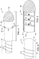
FIG. 1 is a schematic view of a screw in adjustable rear tip extender device, according to some embodiments. -
FIG. 2 illustrates a detailed view of the support member ofFIG. 1 . -
FIG. 3 illustrates an exploded view of extension segments ofFIG. 1 . -
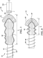
FIG. 4 is a perspective view of click lock rear tip extender device, according to some embodiments. -
FIG. 5 illustrates a detailed view of the bellows segment ofFIG. 4 . -
FIG. 6 illustrates a cross-sectional view, rotated 90 degrees, of the bevels segment ofFIG. 4 . -
FIG. 7 is a schematic view of another screw in adjustable rear tip extender device having an expandable bellows segment in an expanded configuration, according to some embodiments. -
FIG. 8 illustrates the screw in adjustable rear tip extender as inFIG. 7 in an unexpanded configuration. - While the invention is amenable to various modifications and alternative forms, specific aspects have been shown by way of example in the drawings and are described in detail below. The intention, however, is not to limit the invention to the particular aspects described. On the contrary, the invention is intended to cover all modifications, equivalents, and alternatives falling within the scope of the invention as defined by the appended claims.
- Various aspects of the present disclosure are directed toward implantable medical devices for the treatment of male erectile dysfunction. Surgical implantation of prostheses may include penile implants. In certain implant procedures, the implant includes an extension device in order to appropriately size the device to the patient. The extension devices, consistent with various aspects of the present disclosure, may be capable of extending an implant for erectile dysfunction to the desired extension distance.
-
FIG. 1 illustrates anextension device 100, according to some embodiments.Device 100 is an adjustable rear tip extender device. As shown inFIG. 1 , thedevice 100 includes asupport segment 200, a plurality ofextension segments 300, and areceiving segment 400 insertable within thedistal end 50 ofpenile implant 10. Receivingsegment 400 ofdevice 100 may be a screw in feature for attachment ofdevice 100 to thedistal end 50 of apenile implant 10. Theextension segments 300 may include an open central bore or area as shown. - As shown in
FIG. 1 ,support segment 200 has atip portion 220, an end portion 260 (shown inFIG. 2 ), and a threadedportion 240 between thetip portion 220 and theend portion 260.Tip portion 220 includes a rounded shape contoured according to thedistal end 50 of thepenile implant 10 so that thepenile implant 10 anddevice 100 combination has a smooth external surface. The smooth external surface of thetip portion 220 allowsdevice 100 to seamlessly take the place of the end (not shown) of thepenile implant 10. The smooth design oftip portion 220 allows for easier insertion.Tip portion 220 is solid and thus the pivot point will not be altered by the addition ofdevice 100 topenile implant 10, therefore, the stability of thepenile implant 10 is uncompromised. As shown inFIG. 2 ,end portion 260 may be blunt, in other words, a smooth surface free of sharp corners or edges. Advantages of the smooth surface of theend portion 260 include ensuring injury-free insertion by the surgeon while also ensuring that thepenile implant 10 will not be damaged during insertion. - The
device 100 is adjustable to a desired extension distance D1 according to the number and/or width of theextension segments 300 loaded onto thesupport segment 200. In other words, one, two, three, ormore extension segments 300 may at least partially surround or encircle thesupport segment 200 in order to achieve a desired extension distance D1. As shown inFIG. 3 , eachextension segment 300 may have a different length, e.g.,segment 310 having a first length L1,segment 320 having a second length L2,segment 330 having a third length L3. Therefore, the extension distance D1 is adjustable according to whether thesegment 310 and/orsegment 320 and/orsegment 330 is loaded onto thesupport segment 200. Thedevice 100 may be used, for example, to provide a prosthesis having a desired length that is appropriate to the patient. In certain instances, additionalhollow extension segments 300 than the ones shown may be included to further adjust the length as desired. - In some embodiments, the
support segment 200 having tip portion 220 a tip length, Lt, contributes also to the extension distance D1. In a non-limiting example, length Lt contributes 0.5 cm to the extension distance D1. Each segment adds as needed, e.g., in a non-limiting example,segment 310 having length L1 of 0.5 cm,segment 320 having length L2 of 1.0 cm, andsegment 330 having length L3 of 1.5 cm.Segments segments extension segments 300 may each be of the same width or of different widths as in the non-limiting example above. - As shown in
FIG. 1 , receivingsegment 400 is disposed at thedistal end 50 of thepenile implant 10. Receivingsegment 400 is coupled to thesupport segment 200 by rotating thesupport segment 200 into the receivingsegment 400 to secure the device at a desired extension distance D1. Threadedportion 240 includes a plurality ofthreads 250. Receivingsegment 400 includes ahole 420, and thehole 420 including a plurality ofinternal grooves 440. Internal grooves 440 (shown inFIG. 1 ) are configured to matingly receive the plurality of the threads 250 (shown inFIG. 3 ) to secure thesupport segment 200 at the desired extension distance D1. -
Device 100 is attached to apenile implant 10 at thedistal end 50 via receivingsegment 400.Device 100 works by being screwed into the back of thepenile implant 10. Moreover,device 100 includes thenon-hollow support segment 200 to provide greater strength along the extension distance D1. Device 100 may be advantageously safer and more stable than other RTE designs, which were hollow and prone to failure by snapping off due to the pivot point moving anteriorly toward the head of the penis. -
Support segment 200 and/orextension segments 300 and/or receivingsegment 400 of thedevice 100 may include any suitable medical grade material. Examples of such materials include various biopolymer, and/or other various biologically compatible materials. In preferred instances, the biopolymer material is hydrophilic. In certain instances, thesupport segment 200 may be Bioflex®. In certain instances, theextension segments 300 may be a Bioflex®. In certain instances, the receivingsegment 400 may be a Bioflex.FIG. 4 illustrates anextension device 500, according to other embodiments.Device 500 may include a click lock rear tip extender device for extending a penile implant. Thedevice 500 includes abellows segment 600 and abevels segment 700. As illustrated in the cross-sectional view ofbellow segment 600 inFIG. 5 , bellowssegment 600 has ahollow body portion 620 and arounded tip portion 660. In some embodiments, the roundedtip portion 660 includes a shape contoured according to the distal end of the penile implant. In some embodiments, thetip portion 660 may be solid. - As shown in
FIG. 5 , thehollow body portion 620 includes acircumferential wall 630 having a plurality ofinternal grooves 640. Thecircumferential wall 630 further includes at least oneaperture 650 through thecircumferential wall 630. The at least oneaperture 650 is adjacent and perpendicular to aninternal groove 640. In some embodiments, the at least oneaperture 650 may include a shape, such as a circular or rectangular shape. In some embodiments, thecircumferential wall 630 includes a pair ofapertures 655 disposed 180 degrees apart (as shown inFIG. 4 ). Each of theapertures 650 in the pair ofapertures 655 is adjacent and perpendicular to aninternal groove 640. In yet other embodiments, thecircumferential wall 630 includes at least two pairs ofapertures 655 with each pair ofapertures 655 offset longitudinally and configured to facilitate different desired extension distances D2. As shown inFIG. 5 , eachaperture 650 is offset longitudinally. In various embodiments,circumferential wall 630 may include three pairs ofapertures 655, or four pairs ofapertures 655, or more, with each pair ofapertures 655 offset longitudinally to allow adjusting thedevice 500 to a desired extension distances D2. - As shown in
FIGs. 4 and 6 ,bevels segment 700 includes a plurality ofexternal bevels 720 in afirst portion 740 for mating with a distal end of a penile implant (not shown). Thebevels segment 700 includes at least oneprotrusion 760 in asecond portion 780. The at least oneprotrusion 760 is spirally rotatable to engage with the plurality ofinternal grooves 640 of thebellows segment 600 and lock into place within the at least oneaperture 650. The at least oneprotrusion 760 may be clicked or locked into place to the at least oneaperture 650 when aligned at a desired extension distance D2. In some embodiments, the at least oneprotrusion 760 may include a shape, such as a circular or rectangular shape, to matingly engage with the at least oneaperture 650. In some embodiments,portion 780 includes a pair of protrusions 765, which may be clicked or locked into place to a pair ofapertures 655 when aligned at a desired extension distance D2. - In certain instances, the aperture(s) 650 may have dimensions different from the protrusion(s) 760 to facilitate a snap fit. In certain instances, the protrusion(s) 760 of
bevels segment 700 are disengaged from thebellow segment 600 to adjust the distance D2 and then reengaged by mating the protrusion(s) 760 to another longitudinally offsetaperture 650 or pair ofapertures 655. -
Bellows segment 600 and/orbevels segment 700 of thedevice 500 may include any suitable medical grade material. Examples of such materials include various biopolymer, and/or other various biologically compatible materials. In certain instances, thebellows segment 600 may be Bioflex®. In certain instances, thebevels segment 700 may be a Bioflex®. -
FIG. 7 illustrates anextension device 800, according to some embodiments.Device 800 is another adjustable rear tip extender device. As shown inFIG. 7 , thedevice 800 includes asupport segment 900 having atip portion 920, a threadedportion 940, and an expandable bellowssegment 960. Expandable bellowssegment 960 is arranged between thetip portion 920 and the threadedportion 940. Expandable bellowssegment 960 is hollow. Threadedportion 940 includes a plurality ofthreads 950. - As shown in
FIG. 7 , thetip portion 920 further includes aport 980 configured to receive a fluid F. Fluid F may include biomedically compatible fluids such as. Fluid F is injected intoport 980 via adelivery apparatus 1000, which may be a syringe. As fluid F is injected or otherwise delivered intoport 980, fluid F passes throughtip 920 and is received by the expandable bellowssegment 960. As fluid F is filled into the expandable bellowssegment 960, into the expandable bellowssegment 960 is elongated to expand longitudinally to a desired distance. Advantageously,device 800 is expandable to any desired distance from an initial unexpanded configuration Di, having no fluid F inexpandable bellows segment 960, to a final fully expanding configuration Df, havingexpandable bellows segment 960 fully loaded with fluid F to maximum capacity.FIG. 7 showsexpandable bellows segment 960 in an expanded configuration providing a desired distance D3. Support segment 900 ofFIG. 7 is shown inFIG. 8 in an unfilled, unexpanded configuration providing a distance D4, wherein distance D3 is less than distance D4. Becausedevice 800 may provide any desired distance between an initial (unexpanded) distance Di a final (fully expanded) distance Df, advantageously the desired distance may be tailored to the patient without requiring additional components. - Receiving segment (not shown) of
device 800 may be a screw in feature for attachment ofdevice 800 to thedistal end 50 of a penile implant 10 (similarly as shown inFIG. 1 fordevice 100 having receiving segment 400). For example, receivingsegment 940 may be coupled to a distal end of the penile implant. The receiving segment is configured to rotatably receive the threadedportion 940 having plurality ofthreads 950 to secure thesupport segment 900 to thepenile implant 10. -
Support segment 900 may be of one-piece construction.Support segment 900 or any portion thereof, includingtip portion 920, threadedportion 940, andexpandable bellows segment 960, of thedevice 800 may include any suitable medical grade material. Examples of such materials include various biopolymer, and/or other various biologically compatible materials. In preferred instances, the biopolymer material is hydrophilic. In certain instances, thesupport segment 900 may be Bioflex®. In certain instances, thetip portion 920 may be a Bioflex®. In certain instances, the threadedportion 940 may be a Bioflex. In certain instances, the expandable bellowssegment 960 may be a Bioflex. In some embodiments, the roundedtip portion 920 includes a shape contoured according to the distal end of the penile implant. In some embodiments, thetip portion 920 may be solid and substantially encirclingport 980. - As the terms are used herein with respect to ranges of measurements (such as those disclosed immediately above), "about" and "approximately" may be used, interchangeably, to refer to a measurement, position, or arrangement, that includes the stated measurement, position, or arrangement and that also includes any measurement, positions, or arrangements that are reasonably close to the stated measurement, position, or arrangement, but that may differ by a reasonably small amount such as will be understood, and readily ascertained, by individuals having ordinary skill in the relevant arts to be attributable to measurement error, differences in measurement and/or manufacturing equipment calibration, human error in reading and/or setting measurements, positions, or arrangements, adjustments made to optimize performance and/or structural parameters in view of differences in measurements, positions, or arrangements associated with other components, particular implementation scenarios, imprecise adjustment and/or manipulation of objects by a person or machine, and/or the like.
- Various modifications and additions can be made to the exemplary embodiments discussed without departing from the scope of the present invention. For example, while the embodiments described above refer to particular features, the scope of this invention also includes embodiments having different combinations of features and embodiments that do not include all of the described features. Accordingly, the scope of the present invention is intended to embrace all such alternatives, modifications, and variations as fall within the scope of the claims, together with all equivalents thereof.
Claims (21)
- A device for extending a penile implant, the device comprising:a support segment having a tip portion and a threaded portion;a receiving segment insertable into a distal end of the penile implant, the receiving segment configured to rotatably receive the threaded portion to secure the support segment to the penile implant; andat least one extension segment configured to at least partially surround the threaded portion to extend a length between the tip portion and the penile implant.
- The device of claim 1, wherein the at least one extension segment comprises a plurality of extension segments.
- The device of claim 2, wherein the plurality of extension segments includes a first extension segment of a first length and a second extension segment of a second length, wherein the first length is different from the second length.
- The device of claim 3, wherein the first extension segment is arranged at the distal end of penile implant and the second extension segment is arranged between the first extension segment and the tip portion.
- The device of claim 2, wherein the plurality of extension segments includes three extension segments configured to at least partially surround the threaded portion.
- The device of claim 1, wherein the tip portion includes a rounded shape contoured according to the distal end of the penile implant.
- The device of claim 1, wherein the support segment comprises a biopolymer material.
- The device of claim 1, wherein the at least one extension segment comprises a biopolymer material.
- The device of claim 1, wherein the receiving segment comprises a biopolymer material.
- The device of claim 1, wherein the at least one extension segment is substantially cylindrical.
- A device for extending a penile implant, the device comprising:a bellows segment having a hollow body portion and a rounded tip portion, the body portion including a circumferential wall having a plurality of internal grooves and at least one aperture adjacent and perpendicular to the internal grooves;a bevels segment having at least one protrusion configured to spirally rotate to engage with the plurality of internal grooves of the bellows segment and lock into place within the at least one aperture.
- The device of claim 11, wherein the at least one aperture includes a pair of apertures disposed 180 degrees apart, the pair of apertures adjacent and perpendicular to the internal grooves.
- The device of claim 12, wherein the circumferential wall includes at least two pairs of apertures offset longitudinally and configured to facilitate desired extension distances.
- The device of claim 11, wherein the rounded tip portion includes a shape contoured according to the distal end of the penile implant.
- The device of claim 11, wherein the bellows segment comprises a biopolymer material.
- The device of claim 11, wherein the bevels segment comprises a biopolymer material.
- A device for extending a penile implant, the device comprising:a support segment having a tip portion, a threaded portion, and an expandable bellows segment arranged between the tip portion and the threaded portion; the tip portion having a port configured to receive a fluid for expanding the expandable bellows segment;a receiving segment coupled to a distal end of the penile implant, the receiving segment configured to rotatably receive the threaded portion to secure the support segment to the penile implant.
- The device of claim 17, wherein the expandable bellows segment is configured to facilitate desired extension distances.
- The device of claim 17, wherein the tip portion includes a rounded shape contoured according to the distal end of the penile implant.
- The device of claim 17, wherein the support segment comprises a biopolymer material.
- The device of claim 17, wherein the support segment is of one-piece construction.
Applications Claiming Priority (1)
| Application Number | Priority Date | Filing Date | Title |
|---|---|---|---|
| US201962818266P | 2019-03-14 | 2019-03-14 |
Publications (2)
| Publication Number | Publication Date |
|---|---|
| EP3708125A2 true EP3708125A2 (en) | 2020-09-16 |
| EP3708125A3 EP3708125A3 (en) | 2020-12-30 |
Family
ID=69810730
Family Applications (1)
| Application Number | Title | Priority Date | Filing Date |
|---|---|---|---|
| EP20162863.3A Pending EP3708125A3 (en) | 2019-03-14 | 2020-03-13 | Rear-tip extender for penile implant |
Country Status (2)
| Country | Link |
|---|---|
| US (2) | US11278410B2 (en) |
| EP (1) | EP3708125A3 (en) |
Cited By (2)
| Publication number | Priority date | Publication date | Assignee | Title |
|---|---|---|---|---|
| USD935477S1 (en) | 2018-11-08 | 2021-11-09 | 11 Health And Technologies Limited | Display screen or portion thereof with graphical user interface |
| US11406525B2 (en) | 2017-11-09 | 2022-08-09 | 11 Health And Technologies Limited | Ostomy monitoring system and method |
Family Cites Families (18)
| Publication number | Priority date | Publication date | Assignee | Title |
|---|---|---|---|---|
| US3672708A (en) | 1970-06-29 | 1972-06-27 | United States Steel Corp | Coupling device |
| US4600223A (en) | 1982-09-21 | 1986-07-15 | Vries Robert De | Tube coupling |
| US4541420A (en) * | 1984-04-26 | 1985-09-17 | Dacomed Corporation | Penile prosthesis utilizing patient controlled cam actuator apparatus |
| US4628912A (en) | 1984-08-20 | 1986-12-16 | Fischell Robert | Adjustable root and tip extenders for the stiffener cylinder of a penile erection device |
| US4943091A (en) | 1988-04-07 | 1990-07-24 | Proprietary Technology, Inc. | Quick connector |
| US5010882A (en) | 1989-11-13 | 1991-04-30 | American Medical Systems, Inc. | Implantable penile prosthesis |
| FR2654922B1 (en) | 1989-11-28 | 1994-07-01 | Subrini Louis | PENIAN FILL IMPLANT. |
| EP0955894A4 (en) | 1995-08-25 | 2001-02-28 | R Thomas Grotz | Stabilizer for human joints |
| JP2001511686A (en) | 1997-02-13 | 2001-08-14 | ボストン サイエンティフィック リミテッド | Methods and apparatus for minimally invasive pelvic surgery |
| US6808489B2 (en) | 2002-05-24 | 2004-10-26 | Ams Research Corporation | Penile prosthesis with improved rear tip extender |
| US7648456B2 (en) | 2005-04-01 | 2010-01-19 | Coloplast A/S | Adapter for penile prosthesis tip extender |
| US8052593B2 (en) | 2006-10-24 | 2011-11-08 | Ams Research Corporation | Implantable malleable penile prosthetic device |
| ES2614809T3 (en) | 2010-08-25 | 2017-06-02 | Coloplast A/S | Penile implant with convertible proximal tip and a method to implant a penile prosthesis |
| US9474610B2 (en) | 2010-12-21 | 2016-10-25 | Boston Scientific Scimed, Inc. | Adjustable length rear tip extender for penile prosthesis |
| US9375314B2 (en) | 2013-07-02 | 2016-06-28 | Wake Forest University Health Sciences | Prosthetic penile implants with tethered rear tip extenders and related methods |
| EP3028673B1 (en) | 2014-12-04 | 2019-07-31 | Coloplast A/S | A base for a penile prosthetic implant and a penile prosthetic system |
| US20170087049A1 (en) * | 2015-09-29 | 2017-03-30 | Timothy Daniel HUTCHISON | Modular adult toy |
| EP3357458A1 (en) | 2017-02-02 | 2018-08-08 | Coloplast A/S | Inflatable penile prosthetic system |
-
2020
- 2020-03-13 US US16/817,625 patent/US11278410B2/en active Active
- 2020-03-13 EP EP20162863.3A patent/EP3708125A3/en active Pending
-
2022
- 2022-01-31 US US17/588,406 patent/US20220168103A1/en active Pending
Cited By (2)
| Publication number | Priority date | Publication date | Assignee | Title |
|---|---|---|---|---|
| US11406525B2 (en) | 2017-11-09 | 2022-08-09 | 11 Health And Technologies Limited | Ostomy monitoring system and method |
| USD935477S1 (en) | 2018-11-08 | 2021-11-09 | 11 Health And Technologies Limited | Display screen or portion thereof with graphical user interface |
Also Published As
| Publication number | Publication date |
|---|---|
| US20200289269A1 (en) | 2020-09-17 |
| US11278410B2 (en) | 2022-03-22 |
| US20220168103A1 (en) | 2022-06-02 |
| EP3708125A3 (en) | 2020-12-30 |
Similar Documents
| Publication | Publication Date | Title |
|---|---|---|
| US20220168103A1 (en) | Device for extending a length of a penile implant | |
| US11504242B2 (en) | Total joint replacement infection control devices and methods | |
| US5122141A (en) | Modular intramedullary nail | |
| US9168156B2 (en) | Trial coupler systems and methods | |
| US7306629B2 (en) | Femoral head assembly with variable offset | |
| EP2489331A3 (en) | Stent structures for use with valve replacement | |
| US9724212B2 (en) | Implant for lower limb amputation | |
| US9480566B2 (en) | Tool with a groove useful for implanting a penile prosthetic cylinder | |
| KR20220125807A (en) | acetabular cup system | |
| RU2673915C1 (en) | Composite adjustable endoprosthesis for cavernous bodies with simplified joint system of components in operative field | |
| EP2608744B1 (en) | Penile implant with convertible proximal tip | |
| US8360959B2 (en) | Penile implant with convertible proximal tip | |
| WO2011023197A1 (en) | Penile prosthesis cap, assembly, and implantation tool | |
| BR112020017903A2 (en) | TEMPORARY SPACE DEVICE FOR HUMAN BODY JOINTS | |
| CN210673514U (en) | Artificial vertebral body for upper cervical vertebra and implant device for upper cervical vertebra | |
| CN210521148U (en) | Cervical vertebra implantation system | |
| RU196245U1 (en) | Implant balloon balloon catheter | |
| CN111683611B (en) | Implants and methods for the treatment of Charcol's foot and other conditions | |
| US20240058130A1 (en) | Rear tip extender having multiple locks for coupling with a penile prosthesis | |
| US11813004B2 (en) | Cervical plate and screw locking mechanism | |
| JP2022514485A (en) | Internal artificial organ set and equipment for knee joint | |
| CN115607340A (en) | Acetabulum patch and acetabulum patch system | |
| BR102018014149A2 (en) | SYSTEM AND METHOD FOR ORTHOPEDIC REPLACEMENT ARTHROPLASTY PROCEDURE |
Legal Events
| Date | Code | Title | Description |
|---|---|---|---|
| PUAI | Public reference made under article 153(3) epc to a published international application that has entered the european phase |
Free format text: ORIGINAL CODE: 0009012 |
|
| STAA | Information on the status of an ep patent application or granted ep patent |
Free format text: STATUS: THE APPLICATION HAS BEEN PUBLISHED |
|
| AK | Designated contracting states |
Kind code of ref document: A2 Designated state(s): AL AT BE BG CH CY CZ DE DK EE ES FI FR GB GR HR HU IE IS IT LI LT LU LV MC MK MT NL NO PL PT RO RS SE SI SK SM TR |
|
| AX | Request for extension of the european patent |
Extension state: BA ME |
|
| PUAL | Search report despatched |
Free format text: ORIGINAL CODE: 0009013 |
|
| AK | Designated contracting states |
Kind code of ref document: A3 Designated state(s): AL AT BE BG CH CY CZ DE DK EE ES FI FR GB GR HR HU IE IS IT LI LT LU LV MC MK MT NL NO PL PT RO RS SE SI SK SM TR |
|
| AX | Request for extension of the european patent |
Extension state: BA ME |
|
| RIC1 | Information provided on ipc code assigned before grant |
Ipc: A61F 2/26 20060101AFI20201123BHEP |
|
| STAA | Information on the status of an ep patent application or granted ep patent |
Free format text: STATUS: REQUEST FOR EXAMINATION WAS MADE |
|
| 17P | Request for examination filed |
Effective date: 20210630 |
|
| RBV | Designated contracting states (corrected) |
Designated state(s): AL AT BE BG CH CY CZ DE DK EE ES FI FR GB GR HR HU IE IS IT LI LT LU LV MC MK MT NL NO PL PT RO RS SE SI SK SM TR |