EP3708103A1 - Elektrodeninstrument und resektoskop mit greiffunktion - Google Patents
Elektrodeninstrument und resektoskop mit greiffunktion Download PDFInfo
- Publication number
- EP3708103A1 EP3708103A1 EP20161222.3A EP20161222A EP3708103A1 EP 3708103 A1 EP3708103 A1 EP 3708103A1 EP 20161222 A EP20161222 A EP 20161222A EP 3708103 A1 EP3708103 A1 EP 3708103A1
- Authority
- EP
- European Patent Office
- Prior art keywords
- contact part
- electrode
- tissue contact
- instrument
- resectoscope
- Prior art date
- Legal status (The legal status is an assumption and is not a legal conclusion. Google has not performed a legal analysis and makes no representation as to the accuracy of the status listed.)
- Granted
Links
Images

Classifications
-
- A—HUMAN NECESSITIES
- A61—MEDICAL OR VETERINARY SCIENCE; HYGIENE
- A61B—DIAGNOSIS; SURGERY; IDENTIFICATION
- A61B18/00—Surgical instruments, devices or methods for transferring non-mechanical forms of energy to or from the body
- A61B18/04—Surgical instruments, devices or methods for transferring non-mechanical forms of energy to or from the body by heating
- A61B18/12—Surgical instruments, devices or methods for transferring non-mechanical forms of energy to or from the body by heating by passing a current through the tissue to be heated, e.g. high-frequency current
- A61B18/14—Probes or electrodes therefor
- A61B18/149—Probes or electrodes therefor bow shaped or with rotatable body at cantilever end, e.g. for resectoscopes, or coagulating rollers
-
- A—HUMAN NECESSITIES
- A61—MEDICAL OR VETERINARY SCIENCE; HYGIENE
- A61B—DIAGNOSIS; SURGERY; IDENTIFICATION
- A61B18/00—Surgical instruments, devices or methods for transferring non-mechanical forms of energy to or from the body
- A61B2018/00053—Mechanical features of the instrument of device
- A61B2018/00059—Material properties
- A61B2018/00071—Electrical conductivity
- A61B2018/00083—Electrical conductivity low, i.e. electrically insulating
-
- A—HUMAN NECESSITIES
- A61—MEDICAL OR VETERINARY SCIENCE; HYGIENE
- A61B—DIAGNOSIS; SURGERY; IDENTIFICATION
- A61B18/00—Surgical instruments, devices or methods for transferring non-mechanical forms of energy to or from the body
- A61B2018/00315—Surgical instruments, devices or methods for transferring non-mechanical forms of energy to or from the body for treatment of particular body parts
- A61B2018/00505—Urinary tract
- A61B2018/00517—Urinary bladder or urethra
-
- A—HUMAN NECESSITIES
- A61—MEDICAL OR VETERINARY SCIENCE; HYGIENE
- A61B—DIAGNOSIS; SURGERY; IDENTIFICATION
- A61B18/00—Surgical instruments, devices or methods for transferring non-mechanical forms of energy to or from the body
- A61B2018/00571—Surgical instruments, devices or methods for transferring non-mechanical forms of energy to or from the body for achieving a particular surgical effect
- A61B2018/00601—Cutting
-
- A—HUMAN NECESSITIES
- A61—MEDICAL OR VETERINARY SCIENCE; HYGIENE
- A61B—DIAGNOSIS; SURGERY; IDENTIFICATION
- A61B18/00—Surgical instruments, devices or methods for transferring non-mechanical forms of energy to or from the body
- A61B2018/00571—Surgical instruments, devices or methods for transferring non-mechanical forms of energy to or from the body for achieving a particular surgical effect
- A61B2018/00625—Vaporization
-
- A—HUMAN NECESSITIES
- A61—MEDICAL OR VETERINARY SCIENCE; HYGIENE
- A61B—DIAGNOSIS; SURGERY; IDENTIFICATION
- A61B18/00—Surgical instruments, devices or methods for transferring non-mechanical forms of energy to or from the body
- A61B18/04—Surgical instruments, devices or methods for transferring non-mechanical forms of energy to or from the body by heating
- A61B18/12—Surgical instruments, devices or methods for transferring non-mechanical forms of energy to or from the body by heating by passing a current through the tissue to be heated, e.g. high-frequency current
- A61B18/1206—Generators therefor
- A61B2018/1246—Generators therefor characterised by the output polarity
- A61B2018/126—Generators therefor characterised by the output polarity bipolar
-
- A—HUMAN NECESSITIES
- A61—MEDICAL OR VETERINARY SCIENCE; HYGIENE
- A61B—DIAGNOSIS; SURGERY; IDENTIFICATION
- A61B18/00—Surgical instruments, devices or methods for transferring non-mechanical forms of energy to or from the body
- A61B18/04—Surgical instruments, devices or methods for transferring non-mechanical forms of energy to or from the body by heating
- A61B18/12—Surgical instruments, devices or methods for transferring non-mechanical forms of energy to or from the body by heating by passing a current through the tissue to be heated, e.g. high-frequency current
- A61B18/14—Probes or electrodes therefor
- A61B2018/1405—Electrodes having a specific shape
- A61B2018/1407—Loop
Definitions
- the invention relates to electrode instruments for use in a resectoscope of the type specified in the preamble of claim 1 and a resectoscope of the type specified in the preamble of claim 10.
- Electrode instruments and resectoscopes of the generic type are used primarily in urology for electrosurgical work in the bladder and urethra. They are commonly used to resect and vaporize tissue, such as tissue in the lower urinary tract.
- the resectoscopes comprise an electrode instrument of the generic type which is mounted within the resectoscope shaft so as to be longitudinally displaceable and, after the insertion of the resectoscope, can be pushed out of the distal end of the shaft with its distal working end.
- the electrode instrument comprises an electrosurgical electrode at its distal working end, for example in the form of a loop or a vaporization button (e.g. plasma buttons).
- Such instruments are for example the OES PRO resectoscopes (Olympus) or other permanent flush resectoscopes according to Iglesias.
- tissue removal is currently often not carried out by means of the resectoscope but with a separately introduced gripping instrument.
- this procedure harbors the risk of successive introduction of the instruments Tissue fragments can be lost or that different insertion openings have to be used when the instruments are introduced at the same time, so that the procedure is less gentle on the patient. For this reason it is desirable to be able to use the same instrument for resection and removal of tissue.
- an electrode instrument with the features of claim 1 and a resectoscope with the features of claim 10.
- the invention therefore relates to an electrode instrument for use in a resectoscope, the electrode instrument having an elongated shaft section with two support arms through which a conductor extends, the one at the distal end of the electrode instrument An electrode which can be acted upon by high-frequency current and which is arranged between the distal ends of the support arms, characterized in that at least one of the support arms has a tissue contact part which is arranged on the outer wall of the support arm and is angled in relation to the longitudinal axis of the support arm in its distal end region for holding tissue fragments.
- the invention in a second aspect, relates to a resectoscope for endoscopic surgery with a cladding tube, characterized in that an electrode instrument according to the invention is mounted in a longitudinally displaceable manner within the cladding tube.
- the resectoscope according to the invention is suitable for various interventions in endoscopic surgery, in particular in electrosurgical surgery.
- the resectoscope can be used for prostate resection.
- the resectoscope can also be used for a large number of other operations, for example for bladder resections.
- the resectoscope according to the invention has a tubular shaft.
- the resectoscope shaft comprises an elongated jacket tube.
- the resectoscope includes a handle system for holding and operating, which usually consists of two handle parts.
- the electrode instrument according to the invention is used as a passage instrument in such a resectoscope.
- the electrode instrument is mounted in the resectoscope so as to be longitudinally displaceable, preferably within the casing tube of the resectoscope.
- the electrode instrument can be external to an inner tube extending in the cladding tube, i. be arranged between the cladding tube and the inner tube or inside the inner tube.
- further through instruments can be arranged in the shaft of the resectoscope.
- the resectoscope usually also includes, for example, rod-shaped optics, a lighting means and / or a rinsing system.
- the electrode instrument has an elongated shaft section which, as described above, is arranged in the interior of the resectoscope shaft so as to be longitudinally displaceable and optionally rotatable about the longitudinal axis.
- the proximal end of the shaft section is functionally connected to a slide of the transporter of the resectoscope, which can be operated by means of the handle.
- an electrode that can be subjected to high-frequency current is formed at the distal end of the electrode instrument.
- the electrode instrument has two support arms, particularly in the shaft section.
- the electrode can be held securely between the distal ends of the two support arms without significantly impairing the view of the surgical site.
- the support arms can extend essentially straight from the distal end to the proximal end of the electrode instrument.
- the support arms can be designed as fork tubes and brought together in a fork proximal to the electrode. This arrangement has proven to be particularly space-saving and stable in some resectoscopes.
- Those skilled in the art are familiar with other suitable designs of the shaft section.
- a conductor extends through the support arms or the shaft section and forms an electrode that can be charged with high-frequency current at the distal end of the electrode instrument.
- This conductor is electrically conductive and can for example be a conductor wire.
- the head is in the area of the support arms to the outside, z. B. electrically isolated from the resectoscope shaft.
- the support arms typically comprise an insulating sheath surrounding the conductor, i. an electrically insulating sheath.
- the insulating sheath can have a hollow cylindrical shape, in the interior of which the conductor runs.
- the conductor is connected to a power source via the proximal section of the resectoscope.
- the electrode formed by the conductor can have different shapes, but is in each case carried between the distal ends of the two support arms.
- the electrode can be, for example, a loop electrode or a vaporization button, the former embodiment being preferred.
- At least one of the support arms has, in its distal end region for holding tissue fragments, a tissue contact part which is arranged on the outer wall of the support arm and is angled in relation to the longitudinal axis of the support arm.
- the tissue contact part arranged on a support arm enables tissue fragments to be held securely without having to load the terminal electrode, so that the tissue fragments are safely and easily removed from the surgical site can.
- the retained tissue fragments are usually pulled out of the sheath of the resectoscope together with an inner shaft and / or the electrode instrument, so that the tissue fragments preferably have a maximum diameter that is smaller than the inner diameter of the sheath.
- the tissue contact part according to the invention is designed and arranged for holding tissue fragments, preferably for holding tissue fragments between the tissue contact part and the distal end of an inner tube and / or the distal end of a through-going instrument of a resectoscope.
- the tissue fragment is thus clamped between the tissue contact part and a component of the resectoscope arranged proximally from the tissue contact part.
- the electrode instrument is first moved distally in such a way that the tissue contact part is arranged distally from a severed tissue fragment, and then withdrawn in the proximal direction into the resectoscope shaft in such a way that the tissue fragment is between the proximal surface of the tissue contact part and one of the above-mentioned further components of the resectoscope is clamped, preferably the distal end of an inner tube and / or a through instrument, such as an optic. It is sufficient here to support the tissue fragment on one side of the inner tube. It is not necessary for the tissue fragment to completely close the distal end of the inner tube.
- the tissue contact part can be designed and arranged for piercing tissue fragments.
- the tissue contacting part in order to hold the tissue fragment, it is not absolutely necessary to support the proximal end of the fragment on a further component of the resectoscope. Instead, the tissue contacting part is sufficiently long to hold an impaled tissue fragment securely.
- the tissue contact part designed for piercing tissue fragments is preferably flat in at least one dimension in order to allow the tissue fragment to be easily impaled.
- the tissue contact part designed for puncturing is preferably designed in the shape of a rod. As will be explained in more detail below, the rod-shaped or differently shaped tissue contact part can be bent or curved in order to be adapted to the dimensions of the resectoscope shaft.
- tissue contact part with a pointed tip. This ensures that a tissue fragment can be punctured, picked up and pushed onto the tissue contact part quickly and safely without falling apart during these steps.
- At least one of the support arms has such a tissue contact part. It is conceivable that tissue contact parts are arranged on both support arms. However, this is not necessary according to the invention. It can be advantageous to arrange a fabric contact part on only one of the support arms. In this way, for example, material and space can be saved.
- the tissue contact part is arranged in the distal end area of the support arm.
- the tissue contact part should be arranged in a resectoscope distal from the distal end of the inner tube and / or through-going instrument. This not only ensures that they are available as clamping partners, but also that there is sufficient space for the tissue fragment inside the cladding tube.
- the tissue contact part can be arranged in the resectoscope, for example in the area of the insulating tip of the resectoscope, with the electrode instrument displaced maximally in the proximal direction. Resectoscopes usually have such an electrically insulating tip at their distal end in order to prevent short circuits between the electrode and the electrically conductive components of the resectoscope.
- the fabric contact part can be arranged in a section of the support arm which is encased by an electrically insulating insulating sleeve.
- the tissue contact part can also be made of an electrically insulating material. This is particularly advantageous because it means that there is no need to maintain an insulating distance between the tissue contact part and the electrode. Suitable electrically insulating materials are known to those skilled in the art and include, for example, ceramics and plastics, in particular thermally stable plastics.
- the fabric contact part can also be arranged in a section of the support arm which is not encased by an electrically insulating insulating sleeve. Then the tissue contact part could e.g. B. be arranged directly on the head. In this embodiment, too, the tissue contact part can be made of an electrically insulating material.
- the fabric contact part is arranged on the outer wall of the support arm and angled in relation to the longitudinal axis of the support arm.
- the longitudinal axis of the tissue contact part can be transverse or essentially transverse to the longitudinal axis of the Support arm run.
- the longitudinal axis of the tissue contact part preferably forms at least an angle of 140 ° to 40 °, more preferably an angle of 120 ° to 60 °, for example approximately 90 °, to the longitudinal axis of the support arm. It goes without saying that the tissue contact part does not have to form this angle with its entire length. Instead, the longitudinal axis of the tissue contact part forms the stated angles at least in sections to the longitudinal axis of the support arm, with at least one section directly connected to the support arm preferably forming the stated angle.
- the shape of the tissue contact part can be adapted to an inner shape of the resectoscope, i.e. be partially designed to complement this shape, z. B. to the inner wall of the cladding tube or the inner tube.
- the tissue contact part can extend away from the support arm in a bent part-circle shape.
- the curvature of the tissue contact part can, for. B. correspond to the curvature of a loop electrode.
- tissue contact part is not arranged directly proximal to (that is, viewed from the distal side: behind) the loop electrode, but rather is arranged on the side of the support arm which faces away from the side into which the loop extends the loop electrode extends.
- the tissue contact part designed for puncturing has a length and the tissue contact part designed for clamping has a proximal surface which are long or large enough to hold the tissue fragment securely.
- the tissue contact part should not slip off the tissue contact part when the inner tube and / or electrode instrument is pulled out of the jacket tube.
- the tissue contact part has, for example, a length which is at least 1/8 of the length of the electrode of the instrument, preferably at least 1/4, more preferably at least 1/2.
- the tissue contact part can extend at least into a sagittal plane of the electrode instrument which, starting from the support arm, extends 1/8 of the distance to the second support arm, preferably 1/4 of the distance.
- Sagittal planes are all planes that extend through the electrode instrument from top to bottom and proximally to distal, the terms “top” and “bottom” referring to a posture of the instrument in which it is normally used and in which for example, the handle of the resectoscope points downwards.
- the sagittal plane in the middle between the two support arms, ie the sagittal plane that extends from the Support arm extends 1/2 the distance to the second support arm, can also be referred to as the median plane.
- the tissue contact part can be arranged at least in sections distal from an inner tube arranged in the cladding tube and / or a through-going instrument arranged in the cladding tube.
- distal denotes an arrangement in which the tissue contact part is arranged in a straight, axial extension of the corresponding component.
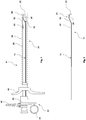
- Fig. 1 shows a sectional view of a resectoscope 12 according to the invention, which comprises an electrode instrument 10 according to the invention.
- Fig. 2 shows the electrode instrument 10 separated from the resectoscope 12.
- the resectoscope 12 comprises a handle 42 and a shaft 54 which has an insulating tip 38 at its distal end.
- the handle 42 is designed to hold the resectoscope 12 in one hand and for, preferably one-handed, actuation of the straight-through instruments extending through the shaft 54.
- the resectoscope 12 shown has a passive conveyor in which the slide 50 is displaced in the distal direction against the distal, first handle part 46 by relative movement of the handle parts 44 and 46 arranged proximally of the shaft 54 against a spring force applied by a spring bridge 48.
- the electrode instrument 10 is forcibly displaced distally in a manner not shown.
- the handle parts 44, 46 are relieved of pressure, the spring force generated by the spring bridge 48 forces the slide 50 back into its rest position, the electrode instrument 10 being pulled in the proximal direction.
- electrosurgical intervention with the electrode instrument 10 can be carried out without manual force on the part of the surgeon, that is to say passively.
- the shaft 54 of the resectoscope 12 comprises a jacket tube 36, in the interior of which a plurality of elongated through-going instruments run, in particular an optic (not shown here) and the electrode instrument 10.
- the optic and other through-going instruments can run in the inner tube 28, which is positioned between the support arms 16, 18 of the Electrode instrument 10 is arranged in the cladding tube 36.
- the electrode instrument 10 is secured in its shaft section 14 against radial displacement by a holding element 40.
- the holding element 40 has a part-circular cross-section, which in the present instrument rests against the outer wall of the inner tube 28. It is also conceivable to support a holding element 40 on other elements of the shaft 54, for example on the inner wall of the cladding tube 36.
- the cross section of the holding element 40 is approximately semicircular in the present case, so that the holding element 40 is positively connected to the outer wall of the inner tube 28 applies and the electrode instrument 10 is still axially displaceable.
- the holding element 40 is partially complementary in shape to the outer wall of the inner tube 28.
- the electrode instrument 10 has an electrode 22 which in the present case is designed as a loop electrode or cutting loop.
- the instrument is designed as a bipolar instrument and is provided with a counter electrode, not shown.
- the loop electrode By means of the loop electrode, the medical professional is able to remove tissue from the surgical site during a surgical procedure.
- the electrode instrument has a tissue contact part 26 on a support arm 16.
- the tissue contact part 26 is arranged in the distal end region 24 of the support arm 16 on its outer wall.
- the electrode 22 is held at a distal distance at the distal end of the support arm 16.
- the tissue contact part 26 extends radially inward from the support arm 16, i. in the direction of the center of the cladding tube 36.
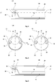
- Fig. 3 shows a detailed, schematic, lateral sectional view of the distal end region of an embodiment of the resectoscope 12 according to the invention.
- the electrode instrument 10 has a tissue contact part 26 which, starting from the support arm 16, extends in the opposite manner to that in FIG Figs. 1 and 2 shown.
- the support arm 16 is shown thinner here than in FIG following figures.
- the electrode instrument 10 is displaced maximally in the proximal direction and is thus completely withdrawn into the casing tube 36.
- both the electrode 22 and the tissue contact part 26 are arranged in the region of the shaft 54 in which the insulating tip 38 forms the distal end of the shaft 54.
- the tissue contact part 26 is arranged distally from the distal end of the inner tube 28 and the through-going instrument 30, which here is a rod-shaped optic.
- the tissue contact part 26 has the shape of a curved rod, as in particular also in FIG Fig. 4 is recognizable, and is therefore suitable for piercing a tissue fragment.
- Fig. 4 shows a schematic front view of the in Fig. 3 end region shown (left) and a schematic sectional view along the axis "LG" in FIG Fig. 3 (right).
- the support arms 16 and 18 pass through the shaft of the resectoscope 12 between the cladding tube 36 and the inner tube 28.
- a through-going instrument 30 is arranged in the interior of the inner tube 28, e.g. B. an optics.
- an electrode 22 in the form of a loop is formed between the support arms 16, 18.
- Both support arms 16, 18 have an insulating sleeve 34 made of an electrically insulating material.
- a conductor 20 in the form of a wire is formed within the insulating sheath 34 and forms the loop electrode at the distal end of the support arms 16, 18.
- the tissue contact part 26 is arranged on the support arm 16 and distanced proximally from the electrode 22 arranged on the support arm.
- the tissue contact part 26 extends from the support arm 16 in approximately the opposite direction relative to the direction in which the electrode 22 extends from the support arm 16. In this way, the arrangement of the tissue contact part 26 does not impede the use of the electrode 22.
- the length of the tissue contact part 26 corresponds approximately to half the length of the electrode 22, the curvature of the two elements being approximately identical.
- the tissue contact part 26 is formed somewhat thicker than the electrode 22.
- Fig. 5 shows a schematic, sectional side view of the in Fig. 3 illustrated end region, wherein a tissue fragment 32 is held on the tissue contact part.
- the tissue fragment 32 was first separated from the surrounding tissue of the patient by means of the electrode 22.
- the tissue contact part 26 was then pierced into the tissue fragment 32. Since the tissue fragment 32 has a size that does not exceed the inside diameter of the cladding tube 36 at any point, this could Tissue fragment 32 can then be withdrawn together with the electrode instrument 10 by axially-proximal displacement of the electrode instrument 10 into the casing tube 36.
- Fig. 6 shows a schematic, lateral sectional illustration of the distal end region of an alternative resectoscope 12 according to the invention.
- the electrode instrument 10 shown here has a tissue contact part 26, which is primarily intended for holding tissue fragments 32 between the tissue contact part 26 and a further component of the resectoscope 12, ie not necessarily for piercing a tissue fragment 32, the latter not being excluded is.
- the Figures 6 to 10 schematically show the same embodiment, the size relationships between the resectoscope components varying for better visibility.
- Fig. 7 shows a schematic front view of the in Fig. 6 shown end area during Fig.
- FIG. 8 a schematic plan view of the electrode instrument that is used in the resectoscope of FIG Fig. 6 is used represents.
- Fig. 9 shows a schematic, sectional side view of the in Fig. 6 illustrated end area, wherein a tissue fragment 32 is held between the tissue contact part 26 and an optic 52.
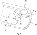
- Fig. 10 shows a schematic, perspective view of the interior of the in Fig. 6 end area shown.
- the tissue contact part 26 extends in the embodiment of FIG Figures 6 to 10 , starting from the support arm 16, beak-shaped or triangular in the direction of the center point of the cladding tube 36. The end of the tissue contact part 26 thereby reaches the sagittal plane S between the support arms, which is the median plane between the two arms. There is no direct connection to the second support arm 18.
- the connecting surface 56 of the tissue contact part 26 directly adjoining the outer wall of the insulating sleeve of the support arm 16 has a concave shape which can nestle against the round surface of the support arm 16. This connecting surface 56 adjoins the support arm at 20 ° or more, preferably at 35 ° or more of its circumference.
- the tissue contact part 26 can have a tubular section which encloses the support arm 16 in a form-fitting manner. In this way, a particularly secure connection between the tissue contact part 26 and the support arm 16 is ensured.
- FIG. 8 The top view shown on the electrode instrument 10 shows that the support arms 16 and 18 extend essentially parallel to one another up to the proximal end of the electrode instrument 10. Both support arms 16, 18 have a conductor 20 on that in Fig. 6 can be seen in which the insulating sleeve 34 is shown in dashed lines.
- the conductor 20 runs through both support arms 16, 18 and forms an electrode 22 at the distal end of the support arms 16, 18.
- the tissue contact part 26 forms an angle ⁇ of approximately 90 ° with the support arm 16.
- the tissue contact part 26 should be curved, for example curved in the proximal direction.
- Electrode instrument 48 Spring bridge 12 Resectoscope 50 Sledge 14th Shaft section 52 optics 16 Beam 54 shaft 18th Beam 56 Interface 20th ladder 22nd electrode 24 distal end area LT Longitudinal support arm 26th Tissue contact part LG Longitudinal axis of the tissue contact part 28 Inner tube ⁇ Angle LT / LG 30th Passage instrument S. Sagittal plane 32 Tissue fragment 34 Insulating sleeve 36 Cladding tube 38 Insulating tip 40 Retaining element 42 Handle 44 Handle part 46 Handle part
Landscapes
- Health & Medical Sciences (AREA)
- Surgery (AREA)
- Engineering & Computer Science (AREA)
- Life Sciences & Earth Sciences (AREA)
- Biomedical Technology (AREA)
- Molecular Biology (AREA)
- Nuclear Medicine, Radiotherapy & Molecular Imaging (AREA)
- Plasma & Fusion (AREA)
- Physics & Mathematics (AREA)
- Heart & Thoracic Surgery (AREA)
- Medical Informatics (AREA)
- Otolaryngology (AREA)
- Animal Behavior & Ethology (AREA)
- General Health & Medical Sciences (AREA)
- Public Health (AREA)
- Veterinary Medicine (AREA)
- Surgical Instruments (AREA)
- Endoscopes (AREA)
Abstract
Description
- Die Erfindung betrifft Elektrodeninstrumente zur Verwendung in einem Resektoskop der im Oberbegriff des Anspruchs 1 genannten Art sowie ein Resektoskop der im Oberbegriff des Anspruchs 10 genannten Art.
- Elektrodeninstrumente und Resektoskope der gattungsgemäßen Art werden vor allem in der Urologie bei elektrochirurgischen Arbeiten in der Blase und der Urethra verwendet. Sie werden üblicherweise zur Resektion und Vaporisation von Gewebe, zum Beispiel von Gewebe im unteren Harntrakt, verwendet. Dazu umfassen die Resektoskope ein gattungsgemäßes Elektrodeninstrument, das innerhalb des Resektoskopschaftes längsverschiebbar gelagert ist und nach dem Einführen des Resektoskops mit seinem distalen Arbeitsende aus dem distalen Ende des Schaftes hervorgeschoben werden kann. Das Elektrodeninstrument umfasst an seinem distalen Arbeitsende eine elektrochirurgische Elektrode, zum Beispiel in Form eines Loops (Schlinge) oder Vaporisationsknopfes (z. B. PlasmaButtons). Solche Instrumente sind zum Beispiel die OES PRO Resektoskope (Olympus) oder andere Dauerspül-Resektoskope nach Iglesias.
- Werden die Elektrodeninstrumente zur Resektion von Gewebe verwendet, so ist es oftmals wünschenswert oder notwendig, das abgetrennte Gewebe von der Eingriffsstelle zu entfernen, z. B. um eine weitere Ausbreitung einer Erkrankung, wie einer Tumorerkrankung, zu verhindern und/oder eine Gewebeprobe für diagnostische Zwecke zu entnehmen. Die Gewebeentnahme wird derzeit oftmals nicht mittels des Resektoskops sondern mit einem separat eingeführten Greifinstrument durchgeführt. Dieses Verfahren birgt jedoch die Risiken, dass bei sukzessiver Einführung der Instrumente Gewebefragmente verloren gehen können oder dass bei gleichzeitiger Einführung der Instrumente verschiedene Einführöffnungen genutzt werden müssen, sodass der Eingriff für den Patienten weniger schonend ist. Aus diesem Grund ist es wünschenswert, dasselbe Instrument für die Resektion und die Entnahme von Gewebe verwenden zu können.
- Verschiedentlich wurden bestehende Resektoskope sowohl zur Geweberesektion als auch zur Entnahme des Gewebes verwendet. Dabei wurde nach der elektrochirurgischen Trennung eines Gewebefragments vom umliegenden Gewebe, z. B. mittels einer Schlingenelektrode, das Gewebefragment zwischen der Schlingenelektrode und dem im Resektoskopschaft angeordneten Innenrohr oder der Optik eingeklemmt. Anschließend wurden Elektrodeninstrument, Gewebefragment und Innenrohr gemeinsam aus dem Außenschaft (Hüllrohr) des Resektoskops und damit auch dem Patienten gezogen. Diese Vorgehensweise birgt jedoch die Gefahr einer Beschädigung der empfindlichen Elektrode. Darüber hinaus ist diese Greiffunktion von der Geometrie und Anordnung von Elektrode und Innenrohr abhängig, sodass bauliche Veränderungen an diesen Elementen zu einem Verlust oder einer Veränderung der Greiffunktion führen können.
- Es besteht daher ein Bedarf an verbesserten Elektrodeninstrumenten und entsprechenden Resektoskopen für die elektrochirurgische Chirurgie mittels derer Gewebe sowohl durchtrennt, als auch aus dem Körper entfernt werden kann.
- Gelöst wird diese Aufgabe durch ein Elektrodeninstrument mit den Merkmalen von Anspruch 1 und ein Resektoskop mit den Merkmalen von Anspruch 10. Erfindungsgemäß ist insbesondere vorgesehen, an mindestens einem der Tragarme des Elektrodeninstruments ein Gewebekontaktteil anzuordnen, zwischen dem und dem distalen Ende des Innenrohrs und/oder eines Durchgangsinstruments Gewebefragmente eingeklemmt oder an dem Gewebefragmente aufgespießt werden können. Die so an dem Elektrodeninstrument oder dem Resektoskop gehaltenen Gewebefragmente können dann dem Körper des Patienten entnommen werden.
- In einem ersten Aspekt betrifft die Erfindung daher ein Elektrodeninstrument zur Verwendung in einem Resektoskop, wobei das Elektrodeninstrument einen langgestreckten Schaftabschnitt mit zwei Tragarmen aufweist, durch die hindurch sich ein Leiter erstreckt, der am distalen Ende des Elektrodeninstruments eine mit Hochfrequenzstrom beaufschlagbare Elektrode bildet, die zwischen den distalen Enden der Tragarme angeordnet ist, dadurch gekennzeichnet, dass mindestens einer der Tragarme in seinem distalen Endbereich zum Halten von Gewebefragmenten ein an der Außenwand des Tragarms angeordnetes, im Verhältnis zur Längsachse des Tragarms abgewinkeltes Gewebekontaktteil aufweist.
- In einem zweiten Aspekt betrifft die Erfindung ein Resektoskop für die endoskopische Chirurgie mit einem Hüllrohr, dadurch gekennzeichnet, dass innerhalb des Hüllrohres ein erfindungsgemäßes Elektrodeninstrument längsverschiebbar gelagert ist. Das erfindungsgemäße Resektoskop ist für verschiedene Eingriffe in der endoskopischen Chirurgie geeignet, insbesondere in der elektrochirurgischen Chirurgie. So kann das Resektoskop beispielsweise für die Prostata-Resektion verwendet werden. Gleichzeitig kann das Resektoskop aber auch für eine Vielzahl anderer Operationen eingesetzt werden, zum Beispiel für Blasen-Resektionen.
- In üblicher Ausbildungsweise weist das erfindungsgemäße Resektoskop einen rohrartigen Schaft auf. Der Resektoskopschaft umfasst ein langgestrecktes Hüllrohr. Neben dem Schaft umfasst das Resektoskop zum Halten und Bedienen ein Griffsystem, das üblicherweise aus zwei Griffteilen besteht.
- Das erfindungsgemäße Elektrodeninstrument wird als Durchgangsinstrument in einem solchen Resektoskop verwendet. Dazu ist das Elektrodeninstrument längsverschiebbar in dem Resektoskop gelagert, vorzugsweise innerhalb des Hüllrohres des Resektoskops. Das Elektrodeninstrument kann außerhalb eines in dem Hüllrohr verlaufenden Innenrohrs, d.h. zwischen Hüllrohr und Innenrohr, angeordnet sein oder innerhalb des Innenrohres. Zusätzlich zu dem Elektrodeninstrument können weitere Durchgangsinstrumente in dem Schaft des Resektoskops angeordnet sein. Üblicherweise umfasst das Resektoskop zusätzlich beispielsweise eine stabförmige Optik, ein Beleuchtungsmittel und/oder ein Spülsystem.
- Das Elektrodeninstrument weist in üblicher Ausbildungsweise einen langgestreckten Schaftabschnitt auf, der im Inneren des Resektoskopschaftes, wie oben beschrieben, längsverschiebbar und optional um die Längsachse rotierbar angeordnet ist. Das proximale Ende des Schaftabschnitts ist funktional mit einem Schlitten des Transporteurs des Resektoskops verbunden, der mittels des Handgriffs betätigt werden kann. Am distalen Ende des Elektrodeninstruments ist eine mit Hochfrequenzstrom beaufschlagbare Elektrode ausgebildet.
- Das Elektrodeninstrument weist, insbesondere im Schaftabschnitt, zwei Tragarme auf. Die Elektrode kann sicher zwischen den distalen Enden der beiden Tragarme gehalten werden, ohne die Sicht auf die Eingriffsstelle in erheblichem Maße zu beeinträchtigen. Die Tragarme können sich vom distalen Ende im Wesentlichen gerade bis zum proximalen Ende des Elektrodeninstruments erstrecken. Alternativ können die Tragarme als Gabelrohre ausgebildet und proximal der Elektrode in einer Gabelung zusammengeführt sein. Diese Anordnung hat sich in einigen Resektoskopen als besonders platzsparend und stabil erwiesen. Fachleuten sind weitere geeignete Ausführungen des Schaftabschnitts geläufig. So ist es beispielsweise auch möglich, die Tragarme proximal der Elektrode in einen rohrförmigen Elektrodenschaft übergehen zu lassen. Auf diese Weise könnte das Elektrodeninstrument gleichzeitig als Innenrohr verwendet werden. Erfindungsgemäß ist es somit nur erforderlich, dass das Elektrodeninstrument in seinem distalen Endbereich zwei Tragarme aufweist, zwischen denen die Elektrode gehalten werden kann.
- Durch die Tragarme bzw. den Schaftabschnitt hindurch erstreckt sich ein Leiter, der am distalen Ende des Elektrodeninstruments eine mit Hochfrequenzstrom beaufschlagbare Elektrode bildet. Dieser Leiter ist elektrisch leitfähig und kann beispielsweise ein Leiterdraht sein. Der Leiter ist im Bereich der Tragarme nach außen, z. B. gegenüber dem Resektoskopschaft elektrisch isoliert. Zu diesem Zweck umfassen die Tragarme in der Regel eine den Leiter umgebene Isolierhülle, d.h. eine elektrisch isolierende Hülle. Die Isolierhülle kann eine Hohlzylinderform aufweisen, in deren Inneren der Leiter verläuft. Am proximalen Ende der Tragarme ist der Leiter über den proximalen Abschnitt des Resektoskops mit einer Stromquelle verbunden.
- Die von dem Leiter gebildete Elektrode kann unterschiedliche Formen aufweisen, wird jedoch jeweils zwischen den distalen Enden der beiden Tragarme getragen. Die Elektrode kann beispielsweise eine Schlingenelektrode oder ein Vaporiationsknopf sein, wobei erstere Ausführung bevorzugt ist.
- Erfindungsgemäß weist mindestens einer der Tragarme in seinem distalen Endbereich zum Halten von Gewebefragmenten ein an der Außenwand des Tragarms angeordnetes, im Verhältnis zur Längsachse des Tragarms abgewinkeltes Gewebekontaktteil auf. Das an einem Tragarm angeordnete Gewebekontaktteil ermöglicht das sichere Halten von Gewebefragmenten, ohne die endständige Elektrode belasten zu müssen, sodass die Gewebefragmente auf sichere und einfache Weise von der Eingriffsstelle entfernt werden können. Die gehaltenen Gewebefragmente werden in der Regel gemeinsam mit einem Innenschaft und/oder dem Elektrodeninstrument aus dem Hüllrohr des Resektoskops herausgezogen werden, sodass die Gewebefragmente vorzugsweise einen maximalen Durchmesser aufweisen, der kleiner ist als der Innendurchmesser des Hüllrohres. Es ist aber auch denkbar, das Resektoskop inklusive eines gehaltenen Gewebefragments vollständig von der Eingriffsstelle zu entfernen, sodass auch größere Gewebefragmente dem Körper eines Patienten entnommen werden können.
- Das erfindungsgemäße Gewebekontaktteil ist zum Halten von Gewebefragmenten ausgebildet und angeordnet, vorzugsweise zum Halten von Gewebefragmenten zwischen dem Gewebekontaktteil und dem distalen Ende eines Innenrohrs und/oder dem distalen Ende eines Durchgangsinstruments eines Resektoskops. In diesen Ausführungen wird das Gewebefragment somit zwischen dem Gewebekontaktteil und einer proximal von dem Gewebekontaktteil angeordneten Komponente des Resektoskops eingeklemmt. Hierzu wird das Elektrodeninstrument zunächst nach distal derart verschoben, dass das Gewebekontaktteil distal von einem abgetrennten Gewebefragment angeordnet ist, und anschließend in proximale Richtung in den Resektoskopschaft derart zurückgezogen, dass das Gewebefragment zwischen der proximalen Oberfläche des Gewebekontaktteils und einer der oben genannten weiteren Komponenten des Resektoskops eingeklemmt wird, vorzugsweise dem distalen Ende eines Innenrohrs und/oder eines Durchgangsinstruments, wie einer Optik. Hierbei ist es ausreichend, das Gewebefragment an einer Seite des Innenrohrs abzustützen. Es ist nicht erforderlich, dass das Gewebefragment das distale Ende des Innenrohres vollständig verschließt.
- Alternativ oder zusätzlich kann das Gewebekontaktteil zum Einstechen in Gewebefragmente ausgebildet und angeordnet sein. In dieser Ausführungsform ist es zum Halten des Gewebefragments nicht zwingend erforderlich, das proximale Ende des Fragments an einer weiteren Komponente des Resektoskops abzustützen. Stattdessen ist das Gewebekontaktteil ausreichend lang, um ein aufgespießtes Gewebefragment sicher zu halten. Das zum Einstechen in Gewebefragmente ausgebildete Gewebekontaktteil ist vorzugsweise in mindestens einer Dimension flach ausgebildet, um ein einfaches Aufspießen des Gewebefragments zu ermöglichen. Vorzugsweise ist das zum Einstechen ausgebildete Gewebekontaktteil stabförmig ausgebildet. Wie weiter unten noch näher erläutert, kann das stabförmige oder anders geformte Gewebekontaktteil dabei gebogen bzw. gekrümmt sein, um den Dimensionen des Resektoskopschaftes angepasst zu werden.
- Es ist auch denkbar, das Gewebekontaktteil mit einer spitz zulaufenden Spitze auszubilden. Hierdurch wird sichergestellt, dass ein Gewebefragment schnell und sicher eingestochen, aufgenommen und auf das Gewebekontaktteil aufgeschoben werden kann ohne bei diesen Schritten auseinanderzufallen.
- Erfindungsgemäß weist mindestens einer der Tragarme ein solches Gewebekontaktteil auf. Es ist denkbar, dass an beiden Tragarmen Gewebekontaktteile angeordnet sind. Dies ist jedoch erfindungsgemäß nicht erforderlich. Es kann vorteilhaft sein, nur an einem der Tragarme ein Gewebekontaktteil anzuordnen. Auf diese Weise kann beispielsweise Material und Platz gespart werden.
- Das Gewebekontaktteil ist im distalen Endbereich des Tragarmes angeordnet. Das Gewebekontaktteil sollte in einem Resektoskop distal von dem distalen Ende des Innenrohres und/oder Durchgangsinstruments angeordnet sein. So wird nicht nur sichergestellt, dass dieselben als Klemmpartner zur Verfügung stehen, sondern auch, dass ausreichend Platz für das Gewebefragment im Inneren des Hüllrohres zur Verfügung steht. Das Gewebekontaktteil kann im Resektoskop bei maximal nach proximal verschobenem Elektrodeninstrument beispielsweise im Bereich der Isolierspitze des Resektoskops angeordnet sein. Üblicherweise weisen Resektoskope an ihrem distalen Ende eine solche elektrisch isolierende Spitze auf, um Kurzschlüsse zwischen der Elektrode und den elektrisch leitfähigen Komponenten des Resektoskops zu verhindern.
- Das Gewebekontaktteil kann in einem Abschnitt des Tragarms angeordnet sein, der von einer elektrisch isolierenden Isolierhülle ummantelt ist. Auch das Gewebekontaktteil kann aus einem elektrisch isolierenden Material sein. Dies ist besonders vorteilhaft, da so kein Isolierabstand zwischen dem Gewebekontaktteil und der Elektrode eingehalten werden muss. Geeignete elektrisch isolierende Materialien sind Fachleuten bekannt und umfassen beispielsweise Keramiken und Kunststoffe, insbesondere thermostabile Kunststoffe. Alternativ kann das Gewebekontaktteil aber auch in einem Abschnitt des Tragarms angeordnet sein, der nicht von einer elektrisch isolierenden Isolierhülle ummantelt ist. Dann könnte das Gewebekontaktteil z. B. unmittelbar am Leiter angeordnet sein. Auch in dieser Ausführungsform kann das Gewebekontaktteil aus einem elektrisch isolierenden Material sein.
- Das Gewebekontaktteil ist jeweils an der Außenwand des Tragarms angeordnet und im Verhältnis zur Längsachse des Tragarms abgewinkelt. So kann die Längsachse des Gewebekontaktteils beispielsweise quer oder im Wesentlichen quer zur Längsachse des Tragarms verlaufen. Die Längsachse des Gewebekontaktteils bildet zur Längsachse des Tragarms jedoch vorzugsweise mindestens einen Winkel von 140° bis 40°, stärker bevorzugt einen Winkel von 120° bis 60°, beispielsweise etwa 90°. Es versteht sich, dass das Gewebekontaktteil diesen Winkel nicht mit seiner gesamten Länge bilden muss. Stattdessen bildet die Längsachse des Gewebekontaktteils die genannten Winkel mindestens abschnittsweise zur Längsachse des Tragarms, wobei bevorzugt mindestens ein mit dem Tragarm unmittelbar verbundener Abschnitt den genannten Winkel bildet.
- Wie oben bereits angedeutet, kann die Form des Gewebekontaktteils an eine Innenform des Resektoskops angepasst sein, d.h. teilweise formkomplementär zu dieser ausgebildet sein, z. B. zur Innenwand des Hüllrohres oder des Innenrohres. So kann sich das Gewebekontaktteil beispielsweise ausgehend von dem Tragarm teilkreisförmig gebogen von dem Tragarm weg erstrecken. Die Krümmung des Gewebekontaktteils kann dabei z. B. der Krümmung einer Schlingenelektrode entsprechen. Bei derart gekrümmten Gewebekontaktteilen ist es bevorzugt, dass das Gewebekontaktteil nicht direkt proximal von (d.h. von distal aus gesehen: hinter) der Schlingenelektrode angeordnet ist, sondern auf der Seite des Tragarms angeordnet ist, welche von der Seite abgewandt ist, in die sich die Schlinge der Schlingenelektrode erstreckt.
- Erfindungsgemäß weist das zum Einstechen ausgebildete Gewebekontaktteil eine Länge auf und das zum Einklemmen ausgebildete Gewebekontaktteil eine proximale Fläche auf, die lang bzw. groß genug sind, um das Gewebefragment sicher zu halten. Insbesondere sollte das Gewebekontaktteil bei dem Herausziehen des Innenrohres und/oder Elektrodeninstruments aus dem Hüllrohr nicht von dem Gewebekontaktteil abrutschen. Um ein Abrutschen von dem zum Einstechen ausgebildeten Gewebekontaktteil auszuschließen, weist das Gewebekontaktteil zum Beispiel eine Länge auf, die mindestens 1/8 der Länge der Elektrode des Instruments ist, vorzugsweise mindestens 1/4, stärker bevorzugt mindestens 1/2. Das Gewebekontaktteil kann sich ausgehend von dem Tragarm mindestens bis in eine Sagittalebene des Elektrodeninstruments erstrecken, die sich ausgehend von dem Tragarm auf 1/8 der Entfernung zum zweiten Tragarm erstreckt, vorzugsweise 1/4 der Entfernung. Als Sagittalebenen werden alle Ebenen bezeichnet, die sich durch das Elektrodeninstrument von oben nach unten und proximal nach distal erstrecken, wobei die Angaben "oben" und "unten" sich auf eine Haltung des Instruments beziehen, in der es normalerweise verwendet wird, und in der beispielsweise der Handgriff des Resektoskops nach unten weist. Die Sagittalebene in der Mitte zwischen beiden Tragarmen, d.h. die Sagittalebene, die sich ausgehend von dem Tragarm auf 1/2 der Entfernung zum zweiten Tragarm erstreckt, kann auch als Medianebene bezeichnet werden.
- Um das Halten des Gewebefragments zwischen dem Gewebekontaktteil und einer weiteren Komponente besonders sicher zu gestalten, kann das Gewebekontaktteil mindestens abschnittsweise distal von einem in dem Hüllrohr angeordneten Innenrohr und/oder einem in dem Hüllrohr angeordneten Durchgangsinstrument angeordnet sein. In diesem Zusammenhang bezeichnet der Begriff "distal" eine Anordnung in der das Gewebekontaktteil in gerader, axialer Verlängerung der entsprechenden Komponente angeordnet ist.
- In den Zeichnungen sind Ausführungsbeispiele der Erfindung schematisch dargestellt. Es zeigen:
- Fig. 1
- eine schematische, seitliche Schnittdarstellung eines erfindungsgemäßen Resektoskops;
- Fig. 2
- eine schematische, seitliche Schnittdarstellung eines erfindungsgemäßen Elektrodeninstruments;
- Fig. 3
- eine schematische, seitliche Schnittdarstellung des distalen Endbereichs eines erfindungsgemäßen Resektoskops;
- Fig. 4
- eine schematische Frontalansicht des in
Fig. 3 gezeigten Endbereichs (links) und eine schematische Schnittansicht entlang der Achse "LG" inFig. 3 (rechts); - Fig. 5
- eine schematische, seitliche Schnittdarstellung des in
Fig. 3 dargestellten Endbereichs, wobei ein Gewebefragment auf dem Gewebekontaktteil gehalten ist; - Fig. 6
- eine schematische, seitliche Schnittdarstellung des distalen Endbereichs eines alternativen erfindungsgemäßen Resektoskops;
- Fig. 7
- eine schematische Frontalansicht des in
Fig. 6 gezeigten Endbereichs; - Fig. 8
- eine schematische Draufsicht auf das Elektrodeninstrument, das in dem Resektoskop von
Fig. 6 verwendet ist; - Fig. 9
- eine schematische, seitliche Schnittdarstellung des in
Fig. 6 dargestellten Endbereichs, wobei ein Gewebefragment zwischen dem Gewebekontaktteil und einer Optik gehalten ist; und - Fig. 10
- eine schematische, perspektivische Sicht ins Innere des in
Fig. 6 gezeigten Endbereichs. - Weitere Vorteile, Kennzeichen und Merkmale der vorliegenden Erfindung werden bei der nachfolgenden detaillierten Beschreibung von Ausführungsbeispielen anhand der beigefügten Zeichnungen deutlich. Allerdings ist die Erfindung nicht auf diese Ausführungsbeispiele beschränkt.
-
Fig. 1 zeigt eine Schnittdarstellung eines erfindungsgemäßen Resektoskops 12, das ein erfindungsgemäßes Elektrodeninstrument 10 umfasst.Fig. 2 zeigt das Elektrodeninstrument 10 getrennt von dem Resektoskop 12. In üblicher Ausbildungsweise umfasst das Resektoskop 12 einen Handgriff 42 und einen Schaft 54, der an seinem distalen Ende eine Isolierspitze 38 aufweist. Der Handgriff 42 ist zum Halten des Resektoskops 12 in einer Hand und zur, vorzugsweise einhändigen, Betätigung der durch den Schaft 54 hindurch verlaufenden Durchgangsinstrumente ausgebildet. - Das dargestellte Resektoskop 12 weist einen passiven Transporteur auf, bei dem der Schlitten 50 durch Relativbewegung der proximal von dem Schaft 54 angeordneten Griffteile 44 und 46 zueinander gegen eine von einer Federbrücke 48 aufgebrachte Federkraft in distale Richtung gegen das distale, erste Griffteil 46 verschoben wird. Bei der Verschiebung des Schlittens 50 in distale Richtung gegen das Griffteil 46 wird das Elektrodeninstrument 10 in nicht dargestellter Weise zwangsgeführt nach distal verschoben. Bei einer Entlastung der Griffteile 44, 46 zwingt die von der Federbrücke 48 erzeugte Federkraft den Schlitten 50 zurück in seine Ruheposition, wobei das Elektrodeninstrument 10 in proximale Richtung gezogen wird. Bei der Rückverschiebung des Schlittens 50 kann ohne Handkraft des Operateurs, also passiv, ein elektrochirurgischer Eingriff mit dem Elektrodeninstrument 10 vorgenommen werden.
- Der Schaft 54 des Resektoskops 12 umfasst ein Hüllrohr 36, in dessen Inneren mehrere längliche Durchgangsinstrumente verlaufen, insbesondere eine hier nicht dargestellte Optik und das Elektrodeninstrument 10. Die Optik sowie weitere Durchgangsinstrumente können in dem Innenrohr 28 verlaufen, das zwischen den Tragarmen 16, 18 des Elektrodeninstruments 10 in dem Hüllrohr 36 angeordnet ist. Das Elektrodeninstrument 10 ist dabei zur Stabilisierung in seinem Schaftabschnitt 14 durch ein Halteelement 40 gegen eine radiale Verschiebung gesichert. Das Halteelement 40 weist einen teilkreisförmigen Querschnitt auf, der in dem vorliegenden Instrument an der Außenwand des Innenrohrs 28 anliegt. Es ist auch denkbar, ein Halteelement 40 an anderen Elementen des Schaftes 54 abzustützen, beispielsweise an der Innenwand des Hüllrohres 36. Der Querschnitt des Halteelements 40 ist im vorliegenden Fall in etwa halbkreisförmig, so dass sich das Halteelement 40 formschlüssig an die Außenwand des Innenrohres 28 anlegt und das Elektrodeninstrument 10 weiterhin axial verschiebbar ist. Mit anderen Worten ist das Halteelement 40 teilweise formkomplementär zu der Außenwand des Innenrohres 28.
- An seinem distalen Ende weist das Elektrodeninstrument 10 eine Elektrode 22 auf, die im vorliegenden Fall als Schlingenelektrode bzw. Schneidschlinge ausgebildet ist. Das Instrument ist als bipolares Instrument ausgebildet und mit einer nicht dargestellten Gegenelektrode versehen. Mittels der Schlingenelektrode ist das medizinische Fachpersonal in der Lage, bei einem chirurgischen Eingriff Gewebe von der Eingriffsstelle abzutragen.
- Darüber hinaus weist das Elektrodeninstrument an einem Tragarm 16 ein Gewebekontaktteil 26 auf. Das Gewebekontaktteil 26 ist im distalen Endbereich 24 des Tragarms 16 an dessen Außenwand angeordnet. Die Elektrode 22 ist distal beabstandet am distalen Ende des Tragarms 16 gehalten. In der gezeigten Ausführungsform erstreckt sich das Gewebekontaktteil 26 ausgehend von dem Tragarm 16 nach radial innen, d.h. in Richtung des Mittelpunkts des Hüllrohres 36.
-
Fig. 3 zeigt eine detailliertere, schematische, seitliche Schnittdarstellung des distalen Endbereichs einer Ausführungsform des erfindungsgemäßen Resektoskops 12. Das Elektrodeninstrument 10 weist ein Gewebekontaktteil 26 auf, das sich ausgehend von dem Tragarm 16 in entgegengesetzter Weise erstreckt, wie das in denFig. 1 und 2 gezeigte. Das Gewebekontaktteil 26, insbesondere dessen Längsachse LG, bildet dabei zum Tragarm 16, insbesondere dessen Längsachse LT, einen Winkel α von 90°. Zur Erhöhung der Übersichtlichkeit ist der Tragarm 16 hier dünner dargestellt als in den folgenden Figuren. Das Elektrodeninstrument 10 ist in der gezeigten Stellung maximal nach proximal verschoben und damit vollständig in das Hüllrohr 36 zurückgezogen. In dieser Stellung sind sowohl die Elektrode 22 als auch das Gewebekontaktteil 26 in dem Bereich des Schaftes 54 angeordnet, in dem die Isolierspitze 38 das distale Ende des Schaftes 54 bildet. Gleichzeitig ist das Gewebekontaktteil 26 distal von dem distalen Ende des Innenrohres 28 und des Durchgangsinstruments 30, das hier eine stabförmige Optik ist, angeordnet. - Das Gewebekontaktteil 26 weist die Form eines gekrümmten Stabes auf, wie insbesondere auch in
Fig. 4 erkennbar ist, und ist dadurch zum Einstechen in ein Gewebefragment geeignet.Fig. 4 zeigt eine schematische Frontalansicht des inFig. 3 gezeigten Endbereichs (links) und eine schematische Schnittansicht entlang der Achse "LG" inFig. 3 (rechts). Die Tragarme 16 und 18 durchlaufen den Schaft des Resektoskops 12 zwischen dem Hüllrohr 36 und dem Innenrohr 28. Im Inneren des Innenrohrs 28 ist ein Durchgangsinstrument 30 angeordnet, z. B. eine Optik. Am distalen Ende der Tragarme 16, 18 ist zwischen den Tragarmen 16, 18 eine Elektrode 22 in Schlingenform ausgebildet. Beide Tragarme 16, 18 weisen eine Isolierhülle 34 auf, die aus einem elektrisch isolierenden Material besteht. Innerhalb der Isolierhülle 34 ist ein Leiter 20 in Drahtform ausgebildet, der am distalen Ende der Tragarme 16, 18 die Schlingenelektrode bildet. - Das Gewebekontaktteil 26 ist an dem Tragarm 16 angeordnet und proximal von der am Tragarm angeordneten Elektrode 22 distanziert. Dabei erstreckt sich das Gewebekontaktteil 26 ausgehend von dem Tragarm 16 in etwa in die entgegengesetzte Richtung relativ zu der Richtung in die sich die Elektrode 22 ausgehend von dem Tragarm 16 erstreckt. Auf diese Weise behindert die Anordnung des Gewebekontaktteils 26 die Verwendung der Elektrode 22 nicht. Die Länge des Gewebekontaktteils 26 entspricht in etwa der Hälfte der Länge der Elektrode 22, wobei die Krümmung der beiden Elemente in etwa identisch ist. Dabei ist das Gewebekontaktteil 26 etwas dicker als die Elektrode 22 ausgebildet.
-
Fig. 5 zeigt eine schematische, seitliche Schnittdarstellung des inFig. 3 dargestellten Endbereichs, wobei ein Gewebefragment 32 auf dem Gewebekontaktteil gehalten ist. Das Gewebefragment 32 wurde zunächst mittels der Elektrode 22 von dem umliegenden Gewebe des Patienten getrennt. Anschließend wurde das Gewebekontaktteil 26 in das Gewebefragment 32 eingestochen. Da das Gewebefragment 32 eine Größe aufweist, die an keiner Stelle den Innendurchmesser des Hüllrohres 36 überschreitet, konnte das Gewebefragment 32 anschließend gemeinsam mit dem Elektrodeninstrument 10 durch axial-proximale Verschiebung des Elektrodeninstruments 10 in das Hüllrohr 36 zurückgezogen werden. -
Fig. 6 zeigt eine schematische, seitliche Schnittdarstellung des distalen Endbereichs eines alternativen erfindungsgemäßen Resektoskops 12. Im Unterschied zu dem inFig. 3 bis 5 gezeigten Elektrodeninstrument 10, weist das hier dargestellte Elektrodeninstrument 10 ein Gewebekontaktteil 26 auf, das vorrangig zum Halten von Gewebefragmenten 32 zwischen dem Gewebekontaktteil 26 und einer weiteren Komponente des Resektoskops 12 gedacht ist, d.h. nicht unbedingt zum Einstechen in ein Gewebefragment 32, wobei letztes nicht ausgeschlossen ist. DieFig. 6 bis 10 zeigen schematisch dieselbe Ausführungsform, wobei die Größenverhältnisse zwischen den Resektoskopkomponenten zur besseren Sichtbarkeit variieren.Fig. 7 zeigt eine schematische Frontalansicht des inFig. 6 gezeigten Endbereichs währendFig. 8 eine schematische Draufsicht auf das Elektrodeninstrument, das in dem Resektoskop vonFig. 6 verwendet ist, darstellt.Fig. 9 zeigt eine schematische, seitliche Schnittdarstellung des inFig. 6 dargestellten Endbereichs, wobei ein Gewebefragment 32 zwischen dem Gewebekontaktteil 26 und einer Optik 52 gehalten ist.Fig. 10 zeigt eine schematische, perspektivische Sicht ins Innere des inFig. 6 gezeigten Endbereichs. - Das Gewebekontaktteil 26 erstreckt sich in der Ausführungsform der
Fig. 6 bis 10 , ausgehend von dem Tragarm 16, schnabel- oder dreiecksförmig in Richtung des Mittelpunkts des Hüllrohres 36. Das Ende des Gewebekontaktteils 26 erreicht dabei die Saggitalebene S zwischen den Tragarmen, welche die Medianebene zwischen den beiden Armen ist. Eine direkte Verbindung zu dem zweiten Tragarm 18 besteht nicht. Die unmittelbar an die Außenwand der Isolierhülle des Tragarms 16 angrenzende Verbindungsfläche 56 des Gewebekontaktteils 26 weist eine konkave Form auf, die sich an die runde Oberfläche des Tragarms 16 anschmiegen kann. Diese Verbindungsfläche 56 grenzt auf 20° oder mehr, vorzugsweise auf 35° oder mehr von dessen Umfang an den Tragarm an. Alternativ kann das Gewebekontaktteil 26 einen rohrförmigen Abschnitt aufweisen, der den Tragarm 16 formschlüssig umschließt. Auf diese Weise wird eine besonders sichere Verbindung zwischen Gewebekontaktteil 26 und Tragarm 16 gewährleistet. - Die in
Fig. 8 dargestellte Draufsicht auf das Elektrodeninstrument 10 zeigt, dass die Tragarme 16 und 18 bis zum proximalen Ende des Elektrodeninstruments 10 im Wesentlichen parallel zueinander verlaufen. Beide Tragarme 16, 18 weisen einen Leiter 20 auf, der inFig. 6 erkennbar ist, in der die Isolierhülle 34 gestrichelt dargestellt ist. Der Leiter 20 durchläuft beide Tragarme 16, 18 und bildet am distalen Ende der Tragarme 16, 18 eine Elektrode 22. Das Gewebekontaktteil 26 bildet auch hier zum Tragarm 16 einen Winkel α von etwa 90°. Es ist in weiteren Ausführungsformen angedacht, das Gewebekontaktteil 26 gekrümmt, zum Beispiel nach proximal gekrümmt, auszubilden. - Obwohl die vorliegende Erfindung anhand der Ausführungsbeispiele detailliert beschrieben worden ist, ist für den Fachmann selbstverständlich, dass die Erfindung nicht auf diese Ausführungsbeispiele beschränkt ist, sondern dass vielmehr Abwandlungen in der Weise möglich sind, dass einzelne Merkmale weggelassen oder andersartige Kombinationen der vorgestellten Einzelmerkmale verwirklicht werden können, sofern der Schutzbereich der beigefügten Ansprüche nicht verlassen wird. Die vorliegende Offenbarung schließt sämtliche Kombinationen der vorgestellten Einzelmerkmale ein.
Bezugszeichenliste 10 Elektrodeninstrument 48 Federbrücke 12 Resektoskop 50 Schlitten 14 Schaftabschnitt 52 Optik 16 Tragarm 54 Schaft 18 Tragarm 56 Verbindungsfläche 20 Leiter 22 Elektrode 24 distaler Endbereich LT Längsachse Tragarm 26 Gewebekontaktteil LG Längsachse Gewebekontaktteil 28 Innenrohr α Winkel LT / LG 30 Durchgangsinstrument S Saggitalebene 32 Gewebefragment 34 Isolierhülle 36 Hüllrohr 38 Isolierspitze 40 Halteelement 42 Handgriff 44 Griffteil 46 Griffteil
Claims (12)
- Elektrodeninstrument (10) zur Verwendung in einem Resektoskop (12), wobei das Elektrodeninstrument (10) einen langgestreckten Schaftabschnitt (14) mit zwei Tragarmen (16, 18) aufweist, durch die hindurch sich ein Leiter (20) erstreckt, der am distalen Ende des Elektrodeninstruments (10) eine mit Hochfrequenzstrom beaufschlagbare Elektrode (22) bildet, die zwischen den distalen Enden der Tragarme (16, 18) angeordnet ist, dadurch gekennzeichnet, dass mindestens einer der Tragarme (16, 18) in seinem distalen Endbereich (24) zum Halten von Gewebefragmenten ein an der Außenwand des Tragarms (16, 18) angeordnetes, im Verhältnis zur Längsachse (LT) des Tragarms (16, 18) abgewinkeltes Gewebekontaktteil (26) aufweist.
- Elektrodeninstrument (10) nach Anspruch 1, dadurch gekennzeichnet, dass die Längsachse (LG) des Gewebekontaktteils (26) zur Längsachse (LT) des Tragarms (16, 18) mindestens abschnittsweise einen Winkel (α) von 140° bis 40° bildet.
- Elektrodeninstrument (10) nach einem der Ansprüche 1 oder 2, dadurch gekennzeichnet, dass die Längsachse (LG) des Gewebekontaktteils (26) zur Längsachse (LT) des Tragarms (16, 18) einen Winkel (α) von 120° bis 60° bildet.
- Elektrodeninstrument (10) nach einem der vorangegangenen Ansprüche, dadurch gekennzeichnet, dass das Gewebekontaktteil (26) aus einem elektrisch isolierenden Material ist.
- Elektrodeninstrument (10) nach einem der vorangegangenen Ansprüche, dadurch gekennzeichnet, dass das Gewebekontaktteil (26) in einem Abschnitt des Tragarms (16, 18) angeordnet ist, der von einer elektrisch isolierenden Isolierhülle (34) ummantelt ist.
- Elektrodeninstrument (10) nach einem der vorangegangenen Ansprüche, dadurch gekennzeichnet, dass sich das Gewebekontaktteil (26) ausgehend von dem Tragarm (16, 18) teilkreisförmig gebogen von dem Tragarm (16, 18) weg erstreckt.
- Elektrodeninstrument (10) nach einem der vorangegangenen Ansprüche, dadurch gekennzeichnet, dass sich das Gewebekontaktteil (26) ausgehend von dem Tragarm (16, 18) mindestens bis in eine Sagittalebene (S) des Elektrodeninstruments (10) erstreckt, die sich ausgehend von dem Tragarm (16, 18) auf 1/8 der Entfernung zum zweiten Tragarm (18, 16) erstreckt, vorzugsweise auf 1/4 der Entfernung.
- Elektrodeninstrument (10) nach einem der vorangegangenen Ansprüche, dadurch gekennzeichnet, dass das Gewebekontaktteil (26) zum Halten von Gewebefragmenten (32) zwischen dem Gewebekontaktteil (26) und dem distalen Ende eines Innenrohrs (28) und/oder dem distalen Ende eines Durchgangsinstruments (30) eines Resektoskops (12) ausgebildet und angeordnet ist.
- Elektrodeninstrument (10) nach einem der vorangegangenen Ansprüche, dadurch gekennzeichnet, dass das Gewebekontaktteil (26) zum Einstechen in Gewebefragmente (32) ausgebildet und angeordnet ist.
- Resektoskop (12) für die endoskopische Chirurgie mit einem Hüllrohr (36), dadurch gekennzeichnet, dass innerhalb des Hüllrohres (36) ein Elektrodeninstrument (10) nach einem der Ansprüche 1 bis 9 längsverschiebbar gelagert ist.
- Resektoskop (12) nach Anspruch 10, dadurch gekennzeichnet, dass das Gewebekontaktteil (26) mindestens abschnittsweise distal von einem in dem Hüllrohr (36) angeordneten Innenrohr (28) und/oder einem in dem Hüllrohr angeordneten Durchgangsinstrument (30) angeordnet ist.
- Resektoskop (12) nach Anspruch 10, dadurch gekennzeichnet, dass das Gewebekontaktteil (26) mindestens abschnittsweise proximal von der Elektrode angeordnet ist.
Applications Claiming Priority (1)
| Application Number | Priority Date | Filing Date | Title |
|---|---|---|---|
| DE102019106430.9A DE102019106430A1 (de) | 2019-03-13 | 2019-03-13 | Elektrodeninstrument und Resektoskop mit Greiffunktion |
Publications (2)
| Publication Number | Publication Date |
|---|---|
| EP3708103A1 true EP3708103A1 (de) | 2020-09-16 |
| EP3708103B1 EP3708103B1 (de) | 2021-06-30 |
Family
ID=69779841
Family Applications (1)
| Application Number | Title | Priority Date | Filing Date |
|---|---|---|---|
| EP20161222.3A Active EP3708103B1 (de) | 2019-03-13 | 2020-03-05 | Elektrodeninstrument und resektoskop mit greiffunktion |
Country Status (3)
| Country | Link |
|---|---|
| US (1) | US12251157B2 (de) |
| EP (1) | EP3708103B1 (de) |
| DE (1) | DE102019106430A1 (de) |
Families Citing this family (1)
| Publication number | Priority date | Publication date | Assignee | Title |
|---|---|---|---|---|
| DE102022117282A1 (de) * | 2022-07-11 | 2024-01-11 | Olympus Winter & Ibe Gmbh | Resektoskop und Elektrodeninstrument für ein Resektoskop |
Citations (4)
| Publication number | Priority date | Publication date | Assignee | Title |
|---|---|---|---|---|
| US5196011A (en) * | 1990-10-15 | 1993-03-23 | Olympus Winter & Ibe Gmbh | Cutting electrode for medical resectoscope |
| EP1974683A1 (de) * | 2007-03-30 | 2008-10-01 | Olympus Medical Systems Corp. | Therapeutische Ablationsvorrichtung, Resektoskop |
| US20140171824A1 (en) * | 2012-12-19 | 2014-06-19 | Karl Storz Gmbh & Co. Kg | Endoscopic instrument for retrograde biopsy, in particular synovial biopsy |
| EP3437581A1 (de) * | 2017-08-04 | 2019-02-06 | Olympus Winter & Ibe GmbH | Elektrodeneinheit für ein medizinisches resektoskop |
Family Cites Families (40)
| Publication number | Priority date | Publication date | Assignee | Title |
|---|---|---|---|---|
| US5423813A (en) | 1993-03-18 | 1995-06-13 | Coopersurgical | Resectoscope and electrode assembly |
| US5408992A (en) * | 1993-11-05 | 1995-04-25 | British Technology Group Usa Inc. | Endoscopic device for intraoral use |
| US6149620A (en) | 1995-11-22 | 2000-11-21 | Arthrocare Corporation | System and methods for electrosurgical tissue treatment in the presence of electrically conductive fluid |
| US7572251B1 (en) | 1995-06-07 | 2009-08-11 | Arthrocare Corporation | Systems and methods for electrosurgical tissue treatment |
| JP4157183B2 (ja) | 1998-02-17 | 2008-09-24 | オリンパス株式会社 | 内視鏡用処置具 |
| US6540695B1 (en) | 1998-04-08 | 2003-04-01 | Senorx, Inc. | Biopsy anchor device with cutter |
| US6706039B2 (en) | 1998-07-07 | 2004-03-16 | Medtronic, Inc. | Method and apparatus for creating a bi-polar virtual electrode used for the ablation of tissue |
| DE50110328D1 (de) | 2000-08-26 | 2006-08-10 | Winter & Ibe Olympus | Urologisches resektoskop mit einer monopolaren oder bipolaren elektrode |
| EP2335660B1 (de) | 2001-01-18 | 2018-03-28 | The Regents of The University of California | Chirurgisches Instrument zur minimalinvasiven Behandlung von Glaukoma |
| US6994708B2 (en) | 2001-04-19 | 2006-02-07 | Intuitive Surgical | Robotic tool with monopolar electro-surgical scissors |
| DE10164808B4 (de) | 2001-05-09 | 2010-01-14 | Olympus Winter & Ibe Gmbh | Urologisches Resektoskop mit Isolierkörper |
| US6878149B2 (en) | 2002-03-25 | 2005-04-12 | Acueity, Inc. | Apparatus and method for intraductal abalation |
| JP4441227B2 (ja) | 2003-10-08 | 2010-03-31 | Hoya株式会社 | 高周波処置用内視鏡 |
| JP4495438B2 (ja) | 2003-10-14 | 2010-07-07 | Hoya株式会社 | 内視鏡用高周波処置具 |
| US7150745B2 (en) | 2004-01-09 | 2006-12-19 | Barrx Medical, Inc. | Devices and methods for treatment of luminal tissue |
| US20060030227A1 (en) | 2004-08-06 | 2006-02-09 | George Hairston | Intumescent flame retardent compositions |
| US20060069303A1 (en) | 2004-09-30 | 2006-03-30 | Couvillon Lucien A Jr | Endoscopic apparatus with integrated hemostasis device |
| JPWO2006038645A1 (ja) * | 2004-10-05 | 2008-05-15 | オリンパス株式会社 | 高周波処置装置 |
| DE102005057933B4 (de) | 2005-12-02 | 2015-03-19 | Olympus Winter & Ibe Gmbh | Urologisches Resektoskop mit Isolierkörper am Außenschaft |
| DE102006053338A1 (de) | 2006-11-10 | 2008-05-21 | Steidle, Eduard, Dipl.-Ing. | Aktivelektrode für die HF-Chirurgie |
| GB0903427D0 (en) | 2008-03-20 | 2009-04-08 | Hirvi Ari J | Fluid compositions and methods for the use thereof |
| US20100022824A1 (en) | 2008-07-22 | 2010-01-28 | Cybulski James S | Tissue modification devices and methods of using the same |
| JP5621766B2 (ja) | 2009-04-10 | 2014-11-12 | 住友ベークライト株式会社 | 内視鏡 |
| US8491578B2 (en) | 2009-04-17 | 2013-07-23 | Domain Surgical, Inc. | Inductively heated multi-mode bipolar surgical tool |
| ES2976564T3 (es) | 2011-02-01 | 2024-08-05 | Channel Medsystems Inc | Aparato para el tratamiento criogénico de una cavidad o luz del cuerpo |
| AU2012312066C1 (en) | 2011-09-22 | 2016-06-16 | 460Medical, Inc. | Systems and methods for visualizing ablated tissue |
| DE102011085616A1 (de) | 2011-11-02 | 2013-05-02 | Celon Ag Medical Instruments | Elektrochirurgische Sonde und Elektrochirurgievorrichtung |
| US9277958B2 (en) | 2012-02-22 | 2016-03-08 | Candela Corporation | Reduction of RF electrode edge effect |
| US9895188B2 (en) | 2012-02-22 | 2018-02-20 | Candela Corporation | Reduction of RF electrode edge effect |
| US10499984B2 (en) | 2012-07-18 | 2019-12-10 | Bernard Boon Chye Lim | Apparatus and method for assessing tissue treatment |
| DE102013001156B4 (de) | 2013-01-24 | 2021-10-14 | Bowa-Electronic Gmbh & Co. Kg | Bipolares Resektoskop |
| US20140236143A1 (en) * | 2013-02-19 | 2014-08-21 | Covidien Lp | Electrosurgical electrodes |
| US20150005799A1 (en) | 2013-06-27 | 2015-01-01 | Boston Scientific Scimed, Inc. | Renal nerve modulation balloon having improved robustness |
| DE102013216030A1 (de) | 2013-08-13 | 2015-02-19 | Olympus Winter & Ibe Gmbh | Führungskatheter mit Stabilisierungsmechanismus und Verfahren zum Einführen eines Führungskatheters |
| DE102014004290A1 (de) * | 2014-03-26 | 2015-10-01 | Olympus Winter & Ibe Gmbh | Urologisches Instrument |
| US11382515B2 (en) | 2014-08-07 | 2022-07-12 | Verve Medical, Inc. | Renal denervation using nerve fluorescing dye |
| CN107613849B (zh) | 2014-11-03 | 2021-05-04 | 乔治华盛顿大学 | 用于损伤评估的系统和方法 |
| US10779904B2 (en) | 2015-07-19 | 2020-09-22 | 460Medical, Inc. | Systems and methods for lesion formation and assessment |
| CN109152650B (zh) | 2016-03-18 | 2021-10-26 | 普罗赛普特生物机器人公司 | 用于在出血的闭合组织体积中止血的微创方法和系统 |
| WO2019190459A1 (en) | 2018-03-26 | 2019-10-03 | Zamadar Matibur Rahaman | Multifunctional treatment and diagnostic compositions and methods |
-
2019
- 2019-03-13 DE DE102019106430.9A patent/DE102019106430A1/de not_active Ceased
-
2020
- 2020-03-05 EP EP20161222.3A patent/EP3708103B1/de active Active
- 2020-03-06 US US16/811,675 patent/US12251157B2/en active Active
Patent Citations (4)
| Publication number | Priority date | Publication date | Assignee | Title |
|---|---|---|---|---|
| US5196011A (en) * | 1990-10-15 | 1993-03-23 | Olympus Winter & Ibe Gmbh | Cutting electrode for medical resectoscope |
| EP1974683A1 (de) * | 2007-03-30 | 2008-10-01 | Olympus Medical Systems Corp. | Therapeutische Ablationsvorrichtung, Resektoskop |
| US20140171824A1 (en) * | 2012-12-19 | 2014-06-19 | Karl Storz Gmbh & Co. Kg | Endoscopic instrument for retrograde biopsy, in particular synovial biopsy |
| EP3437581A1 (de) * | 2017-08-04 | 2019-02-06 | Olympus Winter & Ibe GmbH | Elektrodeneinheit für ein medizinisches resektoskop |
Also Published As
| Publication number | Publication date |
|---|---|
| US12251157B2 (en) | 2025-03-18 |
| DE102019106430A1 (de) | 2020-09-17 |
| EP3708103B1 (de) | 2021-06-30 |
| US20200289189A1 (en) | 2020-09-17 |
Similar Documents
| Publication | Publication Date | Title |
|---|---|---|
| EP1221903B1 (de) | Urologisches resektoskop mit einer monopolaren oder bipolaren elektrode | |
| DE2429462C2 (de) | Elektro-chirurgisches Instrument | |
| DE102004037830B4 (de) | Endoskopkappe und endoskopische Schleimhaut-Schneidevorrichtung | |
| EP1005293B1 (de) | Medizinisches instrument zur endoskopischen entnahme der vena saphena magna | |
| EP1891907B1 (de) | Vorrichtung zur Resektion und/oder Ablation von organischem Gewebe mittels Hochfrequenzstrom sowie Resektoskop | |
| EP3649974B1 (de) | Elektrodenanordnung für ein bipolares resektoskop sowie resektoskop | |
| EP3838205B1 (de) | Resektoskop mit distaler elektrodenführung | |
| EP1163886A2 (de) | HF-resektoskopisches Instrument | |
| EP3692938A1 (de) | Lösbarer isoliereinsatz zur verwendung in einem resektoskop | |
| EP3437581A1 (de) | Elektrodeneinheit für ein medizinisches resektoskop | |
| DE102020118265B4 (de) | Medizinisches Instrument und elektrochirurgisches System | |
| EP3708103B1 (de) | Elektrodeninstrument und resektoskop mit greiffunktion | |
| DE10354830B4 (de) | Hochfrequenz-Schneidevorrichtung | |
| EP4046583B1 (de) | Elektrochirurgisches handgerät und kontaktkörper für elektrochirurgisches handgerät | |
| WO2020074355A1 (de) | Resektoskop mit schaftrohrelektrodeninstrument | |
| EP3827775B1 (de) | Transporteur mit verriegelungseinrichtung | |
| DE102023100244A1 (de) | Elektrode für ein elektrochirurgisches Handinstrument | |
| DE19915062C1 (de) | Chirurgisches Instrument | |
| DE102022129542A1 (de) | Elektrode für ein elektrochirurgisches Handinstrument und Verfahren zur Herstellung einer Elektrode | |
| DE3814847C2 (de) | ||
| DE102023123253A1 (de) | Elektrode für ein elektrochirurgisches Handinstrument | |
| DE102016010548B4 (de) | Transporteur | |
| DE102013208167A1 (de) | Applikationssonde | |
| DE102020118059B4 (de) | Medizinisches hf-instrument | |
| DE102022129695A1 (de) | Elektrochirurgisches Handinstrument, Isoliereinsatz und Elektrodenträger für ein elektrochirurgisches Handinstrument |
Legal Events
| Date | Code | Title | Description |
|---|---|---|---|
| PUAI | Public reference made under article 153(3) epc to a published international application that has entered the european phase |
Free format text: ORIGINAL CODE: 0009012 |
|
| STAA | Information on the status of an ep patent application or granted ep patent |
Free format text: STATUS: THE APPLICATION HAS BEEN PUBLISHED |
|
| AK | Designated contracting states |
Kind code of ref document: A1 Designated state(s): AL AT BE BG CH CY CZ DE DK EE ES FI FR GB GR HR HU IE IS IT LI LT LU LV MC MK MT NL NO PL PT RO RS SE SI SK SM TR |
|
| AX | Request for extension of the european patent |
Extension state: BA ME |
|
| STAA | Information on the status of an ep patent application or granted ep patent |
Free format text: STATUS: REQUEST FOR EXAMINATION WAS MADE |
|
| GRAP | Despatch of communication of intention to grant a patent |
Free format text: ORIGINAL CODE: EPIDOSNIGR1 |
|
| STAA | Information on the status of an ep patent application or granted ep patent |
Free format text: STATUS: GRANT OF PATENT IS INTENDED |
|
| 17P | Request for examination filed |
Effective date: 20201106 |
|
| RBV | Designated contracting states (corrected) |
Designated state(s): AL AT BE BG CH CY CZ DE DK EE ES FI FR GB GR HR HU IE IS IT LI LT LU LV MC MK MT NL NO PL PT RO RS SE SI SK SM TR |
|
| INTG | Intention to grant announced |
Effective date: 20201208 |
|
| GRAS | Grant fee paid |
Free format text: ORIGINAL CODE: EPIDOSNIGR3 |
|
| GRAA | (expected) grant |
Free format text: ORIGINAL CODE: 0009210 |
|
| STAA | Information on the status of an ep patent application or granted ep patent |
Free format text: STATUS: THE PATENT HAS BEEN GRANTED |
|
| AK | Designated contracting states |
Kind code of ref document: B1 Designated state(s): AL AT BE BG CH CY CZ DE DK EE ES FI FR GB GR HR HU IE IS IT LI LT LU LV MC MK MT NL NO PL PT RO RS SE SI SK SM TR |
|
| REG | Reference to a national code |
Ref country code: CH Ref legal event code: EP |
|
| REG | Reference to a national code |
Ref country code: DE Ref legal event code: R096 Ref document number: 502020000074 Country of ref document: DE Ref country code: AT Ref legal event code: REF Ref document number: 1405633 Country of ref document: AT Kind code of ref document: T Effective date: 20210715 |
|
| REG | Reference to a national code |
Ref country code: IE Ref legal event code: FG4D Free format text: LANGUAGE OF EP DOCUMENT: GERMAN |
|
| REG | Reference to a national code |
Ref country code: LT Ref legal event code: MG9D |
|
| PG25 | Lapsed in a contracting state [announced via postgrant information from national office to epo] |
Ref country code: BG Free format text: LAPSE BECAUSE OF FAILURE TO SUBMIT A TRANSLATION OF THE DESCRIPTION OR TO PAY THE FEE WITHIN THE PRESCRIBED TIME-LIMIT Effective date: 20210930 Ref country code: HR Free format text: LAPSE BECAUSE OF FAILURE TO SUBMIT A TRANSLATION OF THE DESCRIPTION OR TO PAY THE FEE WITHIN THE PRESCRIBED TIME-LIMIT Effective date: 20210630 Ref country code: FI Free format text: LAPSE BECAUSE OF FAILURE TO SUBMIT A TRANSLATION OF THE DESCRIPTION OR TO PAY THE FEE WITHIN THE PRESCRIBED TIME-LIMIT Effective date: 20210630 |
|
| REG | Reference to a national code |
Ref country code: NL Ref legal event code: MP Effective date: 20210630 |
|
| PG25 | Lapsed in a contracting state [announced via postgrant information from national office to epo] |
Ref country code: NO Free format text: LAPSE BECAUSE OF FAILURE TO SUBMIT A TRANSLATION OF THE DESCRIPTION OR TO PAY THE FEE WITHIN THE PRESCRIBED TIME-LIMIT Effective date: 20210930 Ref country code: LV Free format text: LAPSE BECAUSE OF FAILURE TO SUBMIT A TRANSLATION OF THE DESCRIPTION OR TO PAY THE FEE WITHIN THE PRESCRIBED TIME-LIMIT Effective date: 20210630 Ref country code: SE Free format text: LAPSE BECAUSE OF FAILURE TO SUBMIT A TRANSLATION OF THE DESCRIPTION OR TO PAY THE FEE WITHIN THE PRESCRIBED TIME-LIMIT Effective date: 20210630 Ref country code: RS Free format text: LAPSE BECAUSE OF FAILURE TO SUBMIT A TRANSLATION OF THE DESCRIPTION OR TO PAY THE FEE WITHIN THE PRESCRIBED TIME-LIMIT Effective date: 20210630 Ref country code: GR Free format text: LAPSE BECAUSE OF FAILURE TO SUBMIT A TRANSLATION OF THE DESCRIPTION OR TO PAY THE FEE WITHIN THE PRESCRIBED TIME-LIMIT Effective date: 20211001 |
|
| PG25 | Lapsed in a contracting state [announced via postgrant information from national office to epo] |
Ref country code: SK Free format text: LAPSE BECAUSE OF FAILURE TO SUBMIT A TRANSLATION OF THE DESCRIPTION OR TO PAY THE FEE WITHIN THE PRESCRIBED TIME-LIMIT Effective date: 20210630 Ref country code: EE Free format text: LAPSE BECAUSE OF FAILURE TO SUBMIT A TRANSLATION OF THE DESCRIPTION OR TO PAY THE FEE WITHIN THE PRESCRIBED TIME-LIMIT Effective date: 20210630 Ref country code: ES Free format text: LAPSE BECAUSE OF FAILURE TO SUBMIT A TRANSLATION OF THE DESCRIPTION OR TO PAY THE FEE WITHIN THE PRESCRIBED TIME-LIMIT Effective date: 20210630 Ref country code: PT Free format text: LAPSE BECAUSE OF FAILURE TO SUBMIT A TRANSLATION OF THE DESCRIPTION OR TO PAY THE FEE WITHIN THE PRESCRIBED TIME-LIMIT Effective date: 20211102 Ref country code: NL Free format text: LAPSE BECAUSE OF FAILURE TO SUBMIT A TRANSLATION OF THE DESCRIPTION OR TO PAY THE FEE WITHIN THE PRESCRIBED TIME-LIMIT Effective date: 20210630 Ref country code: RO Free format text: LAPSE BECAUSE OF FAILURE TO SUBMIT A TRANSLATION OF THE DESCRIPTION OR TO PAY THE FEE WITHIN THE PRESCRIBED TIME-LIMIT Effective date: 20210630 Ref country code: SM Free format text: LAPSE BECAUSE OF FAILURE TO SUBMIT A TRANSLATION OF THE DESCRIPTION OR TO PAY THE FEE WITHIN THE PRESCRIBED TIME-LIMIT Effective date: 20210630 Ref country code: CZ Free format text: LAPSE BECAUSE OF FAILURE TO SUBMIT A TRANSLATION OF THE DESCRIPTION OR TO PAY THE FEE WITHIN THE PRESCRIBED TIME-LIMIT Effective date: 20210630 |
|
| PG25 | Lapsed in a contracting state [announced via postgrant information from national office to epo] |
Ref country code: PL Free format text: LAPSE BECAUSE OF FAILURE TO SUBMIT A TRANSLATION OF THE DESCRIPTION OR TO PAY THE FEE WITHIN THE PRESCRIBED TIME-LIMIT Effective date: 20210630 |
|
| REG | Reference to a national code |
Ref country code: DE Ref legal event code: R097 Ref document number: 502020000074 Country of ref document: DE |
|
| PG25 | Lapsed in a contracting state [announced via postgrant information from national office to epo] |
Ref country code: DK Free format text: LAPSE BECAUSE OF FAILURE TO SUBMIT A TRANSLATION OF THE DESCRIPTION OR TO PAY THE FEE WITHIN THE PRESCRIBED TIME-LIMIT Effective date: 20210630 |
|
| PLBE | No opposition filed within time limit |
Free format text: ORIGINAL CODE: 0009261 |
|
| STAA | Information on the status of an ep patent application or granted ep patent |
Free format text: STATUS: NO OPPOSITION FILED WITHIN TIME LIMIT |
|
| PG25 | Lapsed in a contracting state [announced via postgrant information from national office to epo] |
Ref country code: AL Free format text: LAPSE BECAUSE OF FAILURE TO SUBMIT A TRANSLATION OF THE DESCRIPTION OR TO PAY THE FEE WITHIN THE PRESCRIBED TIME-LIMIT Effective date: 20210630 |
|
| 26N | No opposition filed |
Effective date: 20220331 |
|
| PG25 | Lapsed in a contracting state [announced via postgrant information from national office to epo] |
Ref country code: IT Free format text: LAPSE BECAUSE OF FAILURE TO SUBMIT A TRANSLATION OF THE DESCRIPTION OR TO PAY THE FEE WITHIN THE PRESCRIBED TIME-LIMIT Effective date: 20210630 |
|
| PG25 | Lapsed in a contracting state [announced via postgrant information from national office to epo] |
Ref country code: MC Free format text: LAPSE BECAUSE OF FAILURE TO SUBMIT A TRANSLATION OF THE DESCRIPTION OR TO PAY THE FEE WITHIN THE PRESCRIBED TIME-LIMIT Effective date: 20210630 |
|
| REG | Reference to a national code |
Ref country code: BE Ref legal event code: MM Effective date: 20220331 |
|
| PG25 | Lapsed in a contracting state [announced via postgrant information from national office to epo] |
Ref country code: LU Free format text: LAPSE BECAUSE OF NON-PAYMENT OF DUE FEES Effective date: 20220305 Ref country code: IE Free format text: LAPSE BECAUSE OF NON-PAYMENT OF DUE FEES Effective date: 20220305 |
|
| PG25 | Lapsed in a contracting state [announced via postgrant information from national office to epo] |
Ref country code: BE Free format text: LAPSE BECAUSE OF NON-PAYMENT OF DUE FEES Effective date: 20220331 |
|
| PG25 | Lapsed in a contracting state [announced via postgrant information from national office to epo] |
Ref country code: LT Free format text: LAPSE BECAUSE OF FAILURE TO SUBMIT A TRANSLATION OF THE DESCRIPTION OR TO PAY THE FEE WITHIN THE PRESCRIBED TIME-LIMIT Effective date: 20210630 |
|
| P01 | Opt-out of the competence of the unified patent court (upc) registered |
Effective date: 20230529 |
|
| REG | Reference to a national code |
Ref country code: CH Ref legal event code: PL |
|
| PG25 | Lapsed in a contracting state [announced via postgrant information from national office to epo] |
Ref country code: LI Free format text: LAPSE BECAUSE OF NON-PAYMENT OF DUE FEES Effective date: 20230331 Ref country code: CH Free format text: LAPSE BECAUSE OF NON-PAYMENT OF DUE FEES Effective date: 20230331 |
|
| PG25 | Lapsed in a contracting state [announced via postgrant information from national office to epo] |
Ref country code: MK Free format text: LAPSE BECAUSE OF FAILURE TO SUBMIT A TRANSLATION OF THE DESCRIPTION OR TO PAY THE FEE WITHIN THE PRESCRIBED TIME-LIMIT Effective date: 20210630 Ref country code: CY Free format text: LAPSE BECAUSE OF FAILURE TO SUBMIT A TRANSLATION OF THE DESCRIPTION OR TO PAY THE FEE WITHIN THE PRESCRIBED TIME-LIMIT Effective date: 20210630 |
|
| PG25 | Lapsed in a contracting state [announced via postgrant information from national office to epo] |
Ref country code: HU Free format text: LAPSE BECAUSE OF FAILURE TO SUBMIT A TRANSLATION OF THE DESCRIPTION OR TO PAY THE FEE WITHIN THE PRESCRIBED TIME-LIMIT; INVALID AB INITIO Effective date: 20200305 |
|
| PG25 | Lapsed in a contracting state [announced via postgrant information from national office to epo] |
Ref country code: MT Free format text: LAPSE BECAUSE OF FAILURE TO SUBMIT A TRANSLATION OF THE DESCRIPTION OR TO PAY THE FEE WITHIN THE PRESCRIBED TIME-LIMIT Effective date: 20210630 |
|
| PGFP | Annual fee paid to national office [announced via postgrant information from national office to epo] |
Ref country code: AT Payment date: 20250417 Year of fee payment: 5 |
|
| PG25 | Lapsed in a contracting state [announced via postgrant information from national office to epo] |
Ref country code: TR Free format text: LAPSE BECAUSE OF FAILURE TO SUBMIT A TRANSLATION OF THE DESCRIPTION OR TO PAY THE FEE WITHIN THE PRESCRIBED TIME-LIMIT Effective date: 20210630 |
|
| PGFP | Annual fee paid to national office [announced via postgrant information from national office to epo] |
Ref country code: GB Payment date: 20260202 Year of fee payment: 7 |
|
| PGFP | Annual fee paid to national office [announced via postgrant information from national office to epo] |
Ref country code: DE Payment date: 20260128 Year of fee payment: 7 |
|
| PGFP | Annual fee paid to national office [announced via postgrant information from national office to epo] |
Ref country code: FR Payment date: 20260209 Year of fee payment: 7 |