EP3708099B1 - Spinal implant structure and kit thereof - Google Patents
Spinal implant structure and kit thereof Download PDFInfo
- Publication number
- EP3708099B1 EP3708099B1 EP20161601.8A EP20161601A EP3708099B1 EP 3708099 B1 EP3708099 B1 EP 3708099B1 EP 20161601 A EP20161601 A EP 20161601A EP 3708099 B1 EP3708099 B1 EP 3708099B1
- Authority
- EP
- European Patent Office
- Prior art keywords
- spinal implant
- implant structure
- expansion
- arm
- netting
- Prior art date
- Legal status (The legal status is an assumption and is not a legal conclusion. Google has not performed a legal analysis and makes no representation as to the accuracy of the status listed.)
- Active
Links
- 239000007943 implant Substances 0.000 title claims description 221
- 239000002639 bone cement Substances 0.000 claims description 38
- 230000001965 increasing effect Effects 0.000 claims description 5
- 230000004044 response Effects 0.000 claims description 4
- 230000007423 decrease Effects 0.000 claims description 3
- 230000008859 change Effects 0.000 claims description 2
- 230000003313 weakening effect Effects 0.000 description 25
- 238000000034 method Methods 0.000 description 9
- 230000008569 process Effects 0.000 description 7
- 230000010412 perfusion Effects 0.000 description 5
- 239000004696 Poly ether ether ketone Substances 0.000 description 4
- 238000005452 bending Methods 0.000 description 4
- 210000000988 bone and bone Anatomy 0.000 description 4
- 229920002530 polyetherether ketone Polymers 0.000 description 4
- 229920000249 biocompatible polymer Polymers 0.000 description 2
- 238000010586 diagram Methods 0.000 description 2
- 238000006073 displacement reaction Methods 0.000 description 2
- 238000009826 distribution Methods 0.000 description 2
- 210000003041 ligament Anatomy 0.000 description 2
- 229910052751 metal Inorganic materials 0.000 description 2
- 239000002184 metal Substances 0.000 description 2
- 238000003825 pressing Methods 0.000 description 2
- 238000010146 3D printing Methods 0.000 description 1
- 208000008035 Back Pain Diseases 0.000 description 1
- 208000010392 Bone Fractures Diseases 0.000 description 1
- 229920000049 Carbon (fiber) Polymers 0.000 description 1
- 206010017076 Fracture Diseases 0.000 description 1
- 206010061246 Intervertebral disc degeneration Diseases 0.000 description 1
- 206010023204 Joint dislocation Diseases 0.000 description 1
- 208000001132 Osteoporosis Diseases 0.000 description 1
- 208000002193 Pain Diseases 0.000 description 1
- 206010041541 Spinal compression fracture Diseases 0.000 description 1
- 229910001069 Ti alloy Inorganic materials 0.000 description 1
- 230000003466 anti-cipated effect Effects 0.000 description 1
- 239000000560 biocompatible material Substances 0.000 description 1
- 239000000316 bone substitute Substances 0.000 description 1
- 239000004917 carbon fiber Substances 0.000 description 1
- 230000006835 compression Effects 0.000 description 1
- 238000007906 compression Methods 0.000 description 1
- 239000000470 constituent Substances 0.000 description 1
- 230000001054 cortical effect Effects 0.000 description 1
- 230000007850 degeneration Effects 0.000 description 1
- 208000018180 degenerative disc disease Diseases 0.000 description 1
- 230000001419 dependent effect Effects 0.000 description 1
- 208000037265 diseases, disorders, signs and symptoms Diseases 0.000 description 1
- 208000035475 disorder Diseases 0.000 description 1
- 238000009760 electrical discharge machining Methods 0.000 description 1
- 230000002708 enhancing effect Effects 0.000 description 1
- 238000002513 implantation Methods 0.000 description 1
- 230000006872 improvement Effects 0.000 description 1
- 208000021600 intervertebral disc degenerative disease Diseases 0.000 description 1
- 238000004519 manufacturing process Methods 0.000 description 1
- 239000000463 material Substances 0.000 description 1
- VNWKTOKETHGBQD-UHFFFAOYSA-N methane Chemical compound C VNWKTOKETHGBQD-UHFFFAOYSA-N 0.000 description 1
- 238000003801 milling Methods 0.000 description 1
- 238000000465 moulding Methods 0.000 description 1
- 230000009467 reduction Effects 0.000 description 1
- 230000002441 reversible effect Effects 0.000 description 1
- 210000000278 spinal cord Anatomy 0.000 description 1
- 230000000087 stabilizing effect Effects 0.000 description 1
Images


Classifications
-
- A—HUMAN NECESSITIES
- A61—MEDICAL OR VETERINARY SCIENCE; HYGIENE
- A61F—FILTERS IMPLANTABLE INTO BLOOD VESSELS; PROSTHESES; DEVICES PROVIDING PATENCY TO, OR PREVENTING COLLAPSING OF, TUBULAR STRUCTURES OF THE BODY, e.g. STENTS; ORTHOPAEDIC, NURSING OR CONTRACEPTIVE DEVICES; FOMENTATION; TREATMENT OR PROTECTION OF EYES OR EARS; BANDAGES, DRESSINGS OR ABSORBENT PADS; FIRST-AID KITS
- A61F2/00—Filters implantable into blood vessels; Prostheses, i.e. artificial substitutes or replacements for parts of the body; Appliances for connecting them with the body; Devices providing patency to, or preventing collapsing of, tubular structures of the body, e.g. stents
- A61F2/02—Prostheses implantable into the body
- A61F2/30—Joints
- A61F2/44—Joints for the spine, e.g. vertebrae, spinal discs
- A61F2/4455—Joints for the spine, e.g. vertebrae, spinal discs for the fusion of spinal bodies, e.g. intervertebral fusion of adjacent spinal bodies, e.g. fusion cages
- A61F2/446—Joints for the spine, e.g. vertebrae, spinal discs for the fusion of spinal bodies, e.g. intervertebral fusion of adjacent spinal bodies, e.g. fusion cages having a circular or elliptical cross-section substantially parallel to the axis of the spine, e.g. cylinders or frustocones
-
- A—HUMAN NECESSITIES
- A61—MEDICAL OR VETERINARY SCIENCE; HYGIENE
- A61B—DIAGNOSIS; SURGERY; IDENTIFICATION
- A61B17/00—Surgical instruments, devices or methods, e.g. tourniquets
- A61B17/56—Surgical instruments or methods for treatment of bones or joints; Devices specially adapted therefor
- A61B17/58—Surgical instruments or methods for treatment of bones or joints; Devices specially adapted therefor for osteosynthesis, e.g. bone plates, screws, setting implements or the like
- A61B17/68—Internal fixation devices, including fasteners and spinal fixators, even if a part thereof projects from the skin
- A61B17/70—Spinal positioners or stabilisers ; Bone stabilisers comprising fluid filler in an implant
- A61B17/7097—Stabilisers comprising fluid filler in an implant, e.g. balloon; devices for inserting or filling such implants
-
- A—HUMAN NECESSITIES
- A61—MEDICAL OR VETERINARY SCIENCE; HYGIENE
- A61B—DIAGNOSIS; SURGERY; IDENTIFICATION
- A61B17/00—Surgical instruments, devices or methods, e.g. tourniquets
- A61B17/56—Surgical instruments or methods for treatment of bones or joints; Devices specially adapted therefor
- A61B17/58—Surgical instruments or methods for treatment of bones or joints; Devices specially adapted therefor for osteosynthesis, e.g. bone plates, screws, setting implements or the like
- A61B17/68—Internal fixation devices, including fasteners and spinal fixators, even if a part thereof projects from the skin
- A61B17/70—Spinal positioners or stabilisers ; Bone stabilisers comprising fluid filler in an implant
- A61B17/7071—Implants for expanding or repairing the vertebral arch or wedged between laminae or pedicles; Tools therefor
-
- A—HUMAN NECESSITIES
- A61—MEDICAL OR VETERINARY SCIENCE; HYGIENE
- A61B—DIAGNOSIS; SURGERY; IDENTIFICATION
- A61B17/00—Surgical instruments, devices or methods, e.g. tourniquets
- A61B17/56—Surgical instruments or methods for treatment of bones or joints; Devices specially adapted therefor
- A61B17/58—Surgical instruments or methods for treatment of bones or joints; Devices specially adapted therefor for osteosynthesis, e.g. bone plates, screws, setting implements or the like
- A61B17/68—Internal fixation devices, including fasteners and spinal fixators, even if a part thereof projects from the skin
- A61B17/70—Spinal positioners or stabilisers ; Bone stabilisers comprising fluid filler in an implant
- A61B17/7074—Tools specially adapted for spinal fixation operations other than for bone removal or filler handling
-
- A—HUMAN NECESSITIES
- A61—MEDICAL OR VETERINARY SCIENCE; HYGIENE
- A61B—DIAGNOSIS; SURGERY; IDENTIFICATION
- A61B17/00—Surgical instruments, devices or methods, e.g. tourniquets
- A61B17/56—Surgical instruments or methods for treatment of bones or joints; Devices specially adapted therefor
- A61B17/58—Surgical instruments or methods for treatment of bones or joints; Devices specially adapted therefor for osteosynthesis, e.g. bone plates, screws, setting implements or the like
- A61B17/68—Internal fixation devices, including fasteners and spinal fixators, even if a part thereof projects from the skin
- A61B17/70—Spinal positioners or stabilisers ; Bone stabilisers comprising fluid filler in an implant
- A61B17/7094—Solid vertebral fillers; devices for inserting such fillers
-
- A—HUMAN NECESSITIES
- A61—MEDICAL OR VETERINARY SCIENCE; HYGIENE
- A61B—DIAGNOSIS; SURGERY; IDENTIFICATION
- A61B17/00—Surgical instruments, devices or methods, e.g. tourniquets
- A61B17/56—Surgical instruments or methods for treatment of bones or joints; Devices specially adapted therefor
- A61B17/58—Surgical instruments or methods for treatment of bones or joints; Devices specially adapted therefor for osteosynthesis, e.g. bone plates, screws, setting implements or the like
- A61B17/88—Osteosynthesis instruments; Methods or means for implanting or extracting internal or external fixation devices
- A61B17/8802—Equipment for handling bone cement or other fluid fillers
- A61B17/8805—Equipment for handling bone cement or other fluid fillers for introducing fluid filler into bone or extracting it
-
- A—HUMAN NECESSITIES
- A61—MEDICAL OR VETERINARY SCIENCE; HYGIENE
- A61B—DIAGNOSIS; SURGERY; IDENTIFICATION
- A61B17/00—Surgical instruments, devices or methods, e.g. tourniquets
- A61B17/56—Surgical instruments or methods for treatment of bones or joints; Devices specially adapted therefor
- A61B17/58—Surgical instruments or methods for treatment of bones or joints; Devices specially adapted therefor for osteosynthesis, e.g. bone plates, screws, setting implements or the like
- A61B17/88—Osteosynthesis instruments; Methods or means for implanting or extracting internal or external fixation devices
- A61B17/885—Tools for expanding or compacting bones or discs or cavities therein
- A61B17/8852—Tools for expanding or compacting bones or discs or cavities therein capable of being assembled or enlarged, or changing shape, inside the bone or disc
- A61B17/8858—Tools for expanding or compacting bones or discs or cavities therein capable of being assembled or enlarged, or changing shape, inside the bone or disc laterally or radially expansible
-
- A—HUMAN NECESSITIES
- A61—MEDICAL OR VETERINARY SCIENCE; HYGIENE
- A61F—FILTERS IMPLANTABLE INTO BLOOD VESSELS; PROSTHESES; DEVICES PROVIDING PATENCY TO, OR PREVENTING COLLAPSING OF, TUBULAR STRUCTURES OF THE BODY, e.g. STENTS; ORTHOPAEDIC, NURSING OR CONTRACEPTIVE DEVICES; FOMENTATION; TREATMENT OR PROTECTION OF EYES OR EARS; BANDAGES, DRESSINGS OR ABSORBENT PADS; FIRST-AID KITS
- A61F2/00—Filters implantable into blood vessels; Prostheses, i.e. artificial substitutes or replacements for parts of the body; Appliances for connecting them with the body; Devices providing patency to, or preventing collapsing of, tubular structures of the body, e.g. stents
- A61F2/02—Prostheses implantable into the body
- A61F2/30—Joints
- A61F2002/30001—Additional features of subject-matter classified in A61F2/28, A61F2/30 and subgroups thereof
- A61F2002/30316—The prosthesis having different structural features at different locations within the same prosthesis; Connections between prosthetic parts; Special structural features of bone or joint prostheses not otherwise provided for
- A61F2002/30535—Special structural features of bone or joint prostheses not otherwise provided for
- A61F2002/30593—Special structural features of bone or joint prostheses not otherwise provided for hollow
Definitions
- the present invention relates to spinal implant structures and, more particularly, to an intervertebral and intravertebral implant and a tool kit thereof.
- the spine also known as the vertebral column, essentially comprises four types of elements, namely the spinal cord, vertebrae, ligaments, and intervertebral discs. Severe osteoporosis, intervertebral disc degeneration, ligament degeneration, joint dislocation, and joint compression may bring mechanical damage to the spine (such as a spinal compression fracture) and thus destabilize the spine. Spinal instability is accompanied by extreme discomfort and pain, thereby predisposing the patient to chronic back pain, spine curvature disorders, and walking disability.
- vertebroplasty which entails placing an implant in a collapsed vertebral body.
- the implant in the collapsed vertebral body expands and thereby restores the collapsed vertebral body to its normal height.
- the implant is filled with a bone autograft or a bone substitute (bone cement) to enhance the stability of the spine with a view to curing spinal instability.
- a conventional spinal implant structure requires an implanting tool in order to be placed in the collapsed vertebral body and then expands.
- spinal implant structures and implanting tools There is a wide variety of commercially available spinal implant structures and implanting tools.
- the prior art is unsatisfactory and thus still has room for improvement.
- US 2002/068939 A1 relates to a device for stabilizing bone including a tubular body having first and second end regions defining a longitudinal axis therebetween.
- a plurality of splines extend from the first end region, the splines including first ends coupled the first end region, and second ends disposed away from the first end region, the second ends being directable from a generally axial collapsed state to a substantially transverse expanded state.
- a plurality of support arms are couples to the splines, and an actuator is coupled to the support arms, the actuator movable axially relative to the elongate body for causing the support arms to direct the second ends of the splines from the collapsed state to the expanded state.
- the device includes another set of splines extending from the second end region or located at an intermediate region of the tubular body.
- a spinal implant structure is known from the US 2005/278036 A1 , from which the preamble of claim 1 derives.
- the present invention relates to a spinal implant structure as claimed hereafter. Preferred embodiments are set forth in the dependent claims.
- the present invention provides a spinal implant structure kit, comprising a spinal implant structure and an operating tool for use with the spinal implant structure.
- the spinal implant structure structurally matches the operating tool so that vertebroplasty can be performed efficiently and easily in terms of the adjustment of the position of the spinal implant structure, expansion of the vertebral body, and perfusion of a bone cement, etc.
- a spinal implant structure comprises a first part, a second part, and at least one expansion arm.
- the second part is disposed along the lengthwise direction of the first part without overlapping the first part.
- the first part has a larger diameter than the second part.
- the at least one expansion arm has one end connecting with the first part and forming an included angle with the first part and the other end being a free end.
- the at least one expansion arm has a support arm.
- the support arm has one end connecting with the expansion arm and the other end connecting with the second part.
- the support arm comprises a plurality of weakened regions.
- the support arm bends at the weakened regions and thus drives the expansion arm to move, so as to increase the included angle and expand the spinal implant structure.
- the first part, second part, expansion arm, and support arm are formed integrally.
- a spinal implant kit comprises the spinal implant structure and the operating tool.
- the operating tool comprises a tool body, a fixing sleeve, a central rod, and an operating handle.
- the tool body has a connecting portion and a gripping portion.
- the connecting portion has a tail provided with a jointing structure for connecting with the spinal implant structure.
- the fixing sleeve fits inside the tool body to fix the distance between a first part and a second part of the spinal implant structure.
- the central rod fits inside the fixing sleeve to connect with the second part directly or connect with the second part through the fixing sleeve.
- the operating handle connects with the central rod and rotates to drive the central rod to move in the lengthwise direction of the first part.
- the present invention provides a spinal implant kit which comprises a spinal implant structure and an operating tool.
- the spinal implant structure is made of a metal or a biocompatible polymer.
- the metal includes a titanium alloy
- the biocompatible polymer includes polyether-ether-ketone (PEEK) and its derivatives.
- PEEK and cancellous bone are closely in hardness.
- carbon fiber reinforced PEEK which is as hard as cortical bone, is applicable to the spinal implant kit of the present invention.
- the present invention is not restrictive of the materials which the spinal implant kit of the present invention is made of, and thus the spinal implant kit of the present invention may also be made of the other biocompatible materials.
- FIG. 1A through FIG. 8C illustrate two different embodiments of a spinal implant structure of the present invention.
- FIG. 1A through FIG. 4B show a spinal implant structure 100 of the first embodiment of the present invention.
- FIG. 5A through FIG. 8C show a spinal implant structure 200 of the second embodiment of the present invention.
- the spinal implant structure 100 which is not netted, is illustrated by FIG. 1A through FIG. 2C .
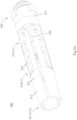
- FIG. 1A and FIG. 1B there are shown a lateral view and a cross-sectional view of the spinal implant structure 100 which is folded, respectively.
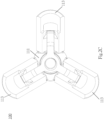
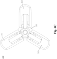
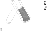
- FIG. 2A through FIG. 2C are a lateral view, a cross-sectional view, and a front view of the spinal implant structure 100 which has been expanded, respectively.
- the spinal implant structure 100 comprises a body 110 and a fixing screw barrel 120.
- the spinal implant structure 100 has an expansion end 101 (left end) and a fixing end 102 (right end).
- the expansion end 101 is expanded with the operating tool (referring to FIG. 1A and FIG. 2A ), and the degree of expansion can be adjusted as needed.
- the body 110 of the spinal implant structure 100 comprises a first part 111, a second part 112, an expansion arm 113, and a support arm 114, and the four parts are formed integrally.
- Both the first part 111 and the second part 112 are hollow-cored cylinders.
- the first part 111 and the second part 112, which are separated and do not overlap (engage), are arranged along the same horizontal axis (X-axis, FIG. 1B ). That is, the first part 111 and the second part 112 are two smaller independent tubes (which may also be called the first tube 111 and the second tube 112) split from the body 110, and the two parts are connected by the expansion arm 113 and the support arm 114.
- the first part 111 contains the fixing screw barrel 120.
- the second part 112 contains a fixing component and a netting (to be described later.)
- the first part 111 has an inner diameter slightly larger than the second part 112 and a length slightly longer than the length of the second part 112.
- the degree of the expansion of the spinal implant structure 100 can be changed by adjusting the distance between the first part 111 and the second part 112. In this embodiment, the degree of the expansion of the spinal implant structure 100 increases, as the first part 111 and the second part 112 get closer to thereby reduce the distance therebetween along the horizontal axis (X-axis).
- an operating tool a central rod, to be described later
- the bending of the expansion arm 113 enables the spinal implant structure 100 to expand.
- An end 113a (first end) of the expansion arm 113 connects with the first part 111 and extends outward from the first part 111.
- the other end 113b (second end) of the expansion arm 113 is a free end which does not connect with any other component.
- a stress weakening portion (weakened section) is defined at a junction 113c of the expansion arm 113 and the first part 111.
- the stress weakening portion is, for example, made thin or hollowed out so that the stress weakening portion (weakened section) is weaker than its surroundings. When subjected to an applied force, the expansion arm 113 bends outward from the stress weakening portion to effectuate expansion.
- the stress weakening portion is a notch which may have a valley, a concave, a V-, a U-shape, etc.
- An included angle ⁇ (shown in FIG. 2B ) smaller than 90 degrees is formed between the expansion arm 113 and the extension line of the first part 111.
- the included angle ⁇ indicates the degree of the expansion of the spinal implant structure 100.
- the included angle ⁇ equals 0 degree when the spinal implant structure 100 is folded ( FIG. 1A and FIG. 1B ).
- the included angle ⁇ is larger than 0 degree but smaller than 90 degrees when the spinal implant structure 100 has been expanded ( FIG. 2A and FIG. 2B ).
- the expansion arm 113 is in the number of one or more.
- the expansion arm 113 is in the number of two or more, the expansion arms 113 connected to the first part 111 are equally spaced apart. As shown in FIG. 2C , in this embodiment, the spinal implant structure 100 comprises three expansion arms 113 spaced apart by 120 degrees. In another embodiment of the present invention, the expansion arms are in the number of two (and thus spaced apart by 180 degrees), four (and thus spaced apart by 90 degrees) or more. The more the expansion arms are provided, the more uniform the distribution of forces required to effectuate expansion is, the smaller each expansion arm is, and the stricter the requirement for product precision is.
- the expansion arm 113 (expansion arm body) has therein a support arm 114.
- the support arm 114 is tongue-like in shape and can be considered as split from the expansion arm 113; in other words, the support arm 114 and the expansion arm 113 are formed integrally. Or, the expansion arm 113 and the support arm 114 can both be considered as split from the body 110.
- the manufacturing process of the spinal implant structure 100 can be further simplified.
- An end 114a (first end) of the support arm 114 is not only connected to the inner side of the expansion arm 113, but also connected to the expansion arm 113 in a manner to be positioned proximate to the first part 111.
- the other end 114b (second end) of the support arm 114 is connected to the second part 112 in a manner to be positioned proximate to the first part 111.
- At least one stress weakening portion (weakened section) is defined at the support arm 114.
- This embodiment is exemplified by two stress weakening portions located at a junction 114c of the support arm 114 and the expansion arm 113 and a junction 114d of the support arm 114 and the second part 112, respectively.
- the support arm 114 bends at the stress weakening portions under a force. As shown in FIG.
- the support arm bends toward the inner side of the spinal implant structure 100, whereas, at the stress weakening portion 114d, the support arm 114 bends toward the outer side of the spinal implant structure 100, thereby driving the expansion arm 113 to bend toward the outer side of the spinal implant structure 100 and thus increasing the included angle ⁇ , so as for the spinal implant structure 100 to expand.
- the stress weakening portions are, for example, made thin or hollowed out so that the stress weakening portions are weaker than their surroundings; hence, when the support arm 114 is subjected to an applied force, the resultant stress is concentrated on the stress weakening portions, thereby causing structural deformation of the support arm 114 (i.e., the bending of the support arm 114).
- the distance between the first part 111 and the second part 112 decreases until the both parts meet. However, the first part 111 and the second part 112 do not overlap with or engage each other.
- the body 110 of the spinal implant structure 100 is preferably formed integrally, for example, by molding, lathing, milling, electrical discharge machining (EDM), 3D printing, or pressing, to form the first part 111, the second part 112, the expansion arm 113, and the support arm 114 by a one-off process.
- EDM electrical discharge machining
- the fixing screw barrel 120 is a hollow-cored cylinder.
- the fixing screw barrel 120 fixes the distance between the first part 111 and the second part 112 upon completion of the expansion of the spinal implant structure 100.
- the fixing screw barrel 120 has a smaller diameter than the first part 111 so as to fit inside the first part 111.
- the fixing screw barrel 120 has an end positioned proximate to the second part 112, and the end has a protruding portion 121.
- the diameter of the protruding portion 121 substantially equals the inner diameter of the second part 112.
- the outer surface of the protruding portion 121 has a first outer thread 121a.
- the first outer thread 121a matches a first inner thread 112a disposed on the inner surface of the second part 112; hence, the protruding portion 121 can be rotated and inserted into the second part 112 so as to be fixed thereto, allowing the fixing screw barrel 120 to abuttingly connect with the second part 112.
- a second inner thread 120a is disposed on the inner surface of the fixing screw barrel 120.
- the second inner thread 120a matches the outer thread (to be described later) of the central rod of the operating tool.
- the user After rotating and inserting the central rod into the fixing screw barrel, the user can pull the central rod and thereby drive the fixing screw barrel 120 and the second part 112 to move, allowing the second part 112 to get closer to the first part 111, so as to effectuate the expansion of the spinal implant structure 100.
- the tail (right end) of the fixing screw barrel 120 is contained in the first part 111.
- the second part 112 moves toward the first part 111, and the tail of the fixing screw barrel 120 protrudes from the first part 111.
- Another screw nut fits around the protruding part of the tail of the fixing screw barrel 120 to prevent the fixing screw barrel 120 from moving toward the second part 112, thereby fixing the distance between the first part 111 and the second part 112.
- an outer thread is disposed on a portion of the outer surface (tail) of the fixing screw barrel 120.
- the wall of the fixing screw barrel 120 has one or at least two through holes 122 whereby a bone cement enters the vertebral body during the bone cement perfusion step (to be described later).
- the spinal implant structure 100 When the spinal implant structure 100 is in an expansion position ( Fig. 2A ), it has a larger internal volume than when it is folded ( Fig. 1A ), and can therefore support and restore a damaged/collapsed vertebral body; also, a large amount of bone cement can be filled in the spinal implant structure 100 to reinforce the support.
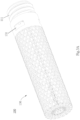
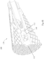
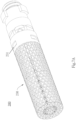
- FIG. 3A through FIG. 4B show that the spinal implant structure 100 has a netting 130 mounted thereon.
- FIG. 3A and FIG. 3B show that the spinal implant structure 100 is folded.
- FIG. 4A and FIG. 4B show that the spinal implant structure 100 has been expanded.
- the netting 130 restricts the range of flow of the bone cement being perfused into the spinal implant structure 100, so as to prevent the bone cement from spilling from the vertebral body, allow the spinal implant structure 100 to be uniformly expanded, and reinforce the vertebral body.
- the netting 130 is hollow-cored and cylindrical in shape.
- the netting 130 fits around the expansion arm 113 of the spinal implant structure 100 and can unfold as a result of the expansion of the spinal implant structure 100 ( FIG. 4B ).
- the openings at the two ends of the netting 130 differ in size.
- the sidewall of the end with a larger opening has at least one engaging hole 131.
- the end is engaged with a first part-facing end of the expansion arm 113.
- the other end of the netting 130 has a fixing hole 132 of a smaller diameter ( FIG. 4A ).
- one end of the netting 130 is fixed to the expansion arm 113 through the engaging hole 131, whereas the other end of the netting 130 is bent to be inserted into the spinal implant structure 100, and in consequence a fixing component 140 is fixed to the second part 112 through the fixing hole 132.
- the fixing component 140 is, for example, a screw whose thread enables it to be rotated and inserted into the second part 112.
- the outer diameter of the screw's head is slightly larger than the diameter of the fixing hole 132 of the netting 130.
- the netting 130 is fixed in place between the screw's head and thread; in other words, the netting 130 is fixed in place at the junction of the fixing component 140 and the second part 112.
- the netting 130 is disconnectably engaged between the fixing component 140 and the second part 112; hence, when the spinal implant structure 100 is expanded ( FIGs.4A , 4B ), that is, at the time when the second part 112 moves toward the first part 111 under a pulling force, the netting 130 is disconnected from the fixing component 140 under the pulling force, thereby allowing the netting 130 to unfold as a result of the expansion of the spinal implant structure 100.
- There are plenty of ways to disconnect the netting 130 from the fixing component 140 including making the screw head of the fixing component 140 slightly larger than the fixing hole 132 and defining it with a lead angle, or providing several notches on the fixing hole 132, but the present invention is not limited thereto. Therefore, when the second part 112 moves toward the first part 111 under a pulling force, the netting 130 can be easily disconnected from the fixing component 140 under a reverse pulling force.
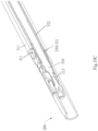
- FIG. 5A through FIG. 6C show that the spinal implant structure 200 is not netted.
- the spinal implant structure 200 of the second embodiment is identical to the spinal implant structure 100 of the first embodiment in terms of most technical features. For the sake of brevity, the identical technical features are not described herein.
- FIG. 5A and FIG. 5B are a lateral view and a cross-sectional view of the spinal implant structure 200 which is folded, respectively.
- FIG. 6A through FIG. 6C are a lateral view, a cross-sectional view, and a front view of the spinal implant structure 200 which has been expanded, respectively.
- the spinal implant structure 200 comprises a body 210 and a fixing screw barrel 220.
- the body 210 is a hollow-cored cylinder
- the fixing screw barrel 220 is also a hollow-cored cylinder.
- the spinal implant structure 200 has an expansion end 201 (left end) and a fixing end 202 (right end).
- the expansion end 201 is expanded with the operating tool (shown in FIG. 5A and FIG. 6A ), and the degree of expansion can be adjusted as needed.
- the body 210 of the spinal implant structure 200 comprises a first part 211, a second part 212, an expansion arm 213 and a support arm 214, and the four parts are integrally formed.
- Both the first part 211 and the second part 212 are hollow-cored cylinders.
- the first part 211 and the second part 212 which are separated and do not overlap, are arranged along the same horizontal axis (X-axis). That is, the first part 211 and the second part 212 can be considered as two smaller independent tubes split from the body 210, and the two parts are connected by the expansion arm 213 and the support arm 214.
- the first part 211 contains the fixing screw barrel 220.
- the second part 212 contains a netting 230 and a fixing component 240 ( FIG.
- the first part 211 has an internal diameter slightly larger than that of the second part 212.
- the degree of the expansion of the spinal implant structure 200 can be changed by adjusting the distance between the first part 211 and the second part 212.
- the second embodiment differs from the first embodiment in that when the first part 211 and the second part 212 move away from each other, that is, the distance between the first part 211 and the second part 212 along the horizontal axis (X-axis) increases, the degree of expansion increases.
- an operating tool (a central rod, to be described later) is required to move the second part 212 toward the expansion end 201 (i.e., leftward), so as to expand the spinal implant structure 200.
- the spinal implant structure 200 is expanded because of the bending of the expansion arm 213.
- the expansion arm 213 has an end 213a (first end) which connects with the first part 211 and extends outward from the first part 211.
- the other end 213b (second end) of the expansion arm 213 is a free end which does not connect with any other component.
- a stress weakening portion(weakened section) is defined at a junction 213c of the expansion arm 213 and the first part 211.
- the stress weakening portion is, for example, made thin or hollowed out so that the stress weakening portion (weakened section) is weaker than its surroundings. When subjected to an applied force, the expansion arm 213 bends outward from the stress weakening portion to effectuate expansion.
- An included angle ⁇ ( FIG.
- the included angle ⁇ indicates the degree of the expansion of the spinal implant structure 200.
- the included angle ⁇ equals 0 degree when the spinal implant structure 200 is folded ( FIG. 5A and FIG. 5B ).
- the included angle ⁇ is larger than 0 degree but smaller than 90 degrees when the spinal implant structure 200 has been expanded ( FIG. 6A and FIG. 6B ).
- the expansion arm 213 is in the number of one or more. If the expansion arm 213 is in the number of two or more, the expansion arms 213 connected to the first part 211 are equally spaced apart. As shown in FIG. 6C , the spinal implant structure 200 comprises three expansion arms 213 spaced apart by 120 degrees.
- the expansion arms are in the number of two (and thus spaced apart by 180 degrees), four (and thus spaced apart by 90 degrees) or more. The more the expansion arms are provided, the more uniform the distribution of forces required to effectuate expansion is, the smaller each expansion arm is, and the stricter the requirement for product precision is.
- the expansion arm 213 has therein a support arm 214.
- the support arm 214 is tongue-like in shape and can be considered as formed by being split from the expansion arm 213; in other words, the support arm 214 and the expansion arm 213 are formed integrally.
- the expansion arm 213 and the support arm 214 can both be considered as being split from the body 210.
- An end 214a (first end) of the support arm 214 is not only connected to the inner side of the expansion arm 213, but also connected to the expansion arm 213 in a manner to be positioned proximate to the free end 213b.
- the other end 214b (second end) of the support arm 214 is connected to the second part 112 in a manner to be positioned distal to the first part 211.
- At least one stress weakening portion is defined at the support arm 214.
- This embodiment is exemplified by two stress weakening portions located at a junction 214c of the support arm 214 and the expansion arm 213 and a junction 214d of the support arm 214 and the second part 212, respectively.
- the support arm 214 bends at the stress weakening portions under a force. As shown in FIG.
- the support arm 214 bends toward the inner side of the spinal implant structure 200, whereas, at the stress weakening portion 214d, the support arm 214 bends toward the outer side of the spinal implant structure 200, thereby driving the expansion arm 213 to bend toward the outer side of the spinal implant structure 200 and thus increasing the included angle ⁇ , so as for the spinal implant structure 200 to expand.
- the stress weakening portions are, for example, made thin or hollowed out so that the stress weakening portions are weaker than their surroundings; hence, when the support arm 214 is subjected to an applied force, the resultant stress is concentrated on the stress weakening portions, thereby causing structural deformation of the support arm 214 (i.e., the bending of the support arm 214).
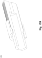
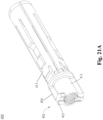
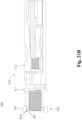
- FIG. 21A and FIG. 21B which illustrate a spinal implant structure 400 according to yet another embodiment of this invention.
- the difference between the spinal implant structure 400 and the above-described spinal implant structure 200 lies in the design of a fixing end 402.
- an engagement positioning block 403 (the same design as in the spinal implant structure 200) is provided at the fixing end 402 (the left end) of the spinal implant structure 400, and is used to engage an operating tool described below.
- a corresponding engaging slot is provided at an engaging end of the operating tool for engaging the spinal implant structure 400.
- An extension rib 404 is also provided on the spinal implant structure 400 and extends from the engagement positioning block 403 toward the inner side of the spinal implant structure 400 (i.e., toward the expansion arm 413).
- the extension rib 404 is used for enhancing the strength of the first part 411 of the spinal implant structure 400, so that structural distortion or fracture can be avoided during the implanting process.
- the engagement positioning block 403 can extend slightly more toward the outer (left) side of the spinal implant structure 400 and have an extra outer protruding block 403A extending out from the fixing end 402 of the spinal implant structure 400.
- the spinal implant structure 400 comprises the outer protruding block 403A, it can more steadily connect with or engage an operating tool (as will be described later) having a corresponding slot or recess structure, and the occurrence of sliding or displacement in the implanting process can be reduced.
- a recess 405 can be arranged at the inner side of a body 410 of the spinal implant structure 400.
- the recess 405 connects to the outside of the body 410, and has an opening in a horizontal direction (X-axis) of the first part 411.
- the recess 405 can be a long concaved slot or groove, and as the recess 405 has one opening end and another closed end, an auxiliary tool (such as a long and thin rod or needle) can be used to reach into the recess 405 from the outside of the body 410 to further apply a force by pressing against the recess 405.
- the force applying thereto can be increased without causing displacement of the spinal implant structure 400, thereby solving the problem of distortion during the implanting process that hampers withdrawal of the operating tool.
- the fixing screw barrel 220 is a hollow-cored cylinder.
- the fixing screw barrel 220 fixes the distance between the first part 211 and the second part 212 upon completion of the expansion of the spinal implant structure 200.
- the fixing screw barrel 220 has a smaller diameter than the first part 211 so as to fit inside the first part 211.
- a third outer thread is disposed on a portion of the outer surface of the fixing screw barrel 220.
- the third outer thread matches a third inner thread disposed on the inner surface of the first part 211.
- the front end of the fixing screw barrel 220 can abuttingly connect with the second part 212 so that the second part 212 is fixed in place, thereby fixing the distance between the first part 211 and the second part 212. Since the fixing screw barrel 220 is adjustably moved forward and backward by the threads, it generates a torque.
- the spinal implant structure 200 in operation does not require the fixing screw barrel 220 to move the second part 212; instead, a central rod (to be described later) of the operating tool moves the second part 212 horizontally away from the first part 211 and thus effectuates the expansion of the spinal implant structure 200, and then the fixing screw barrel 220 is moved forward to abuttingly connect with the second part 212, thereby fixing the second part 212 in place.
- a central rod (to be described later) of the operating tool moves the second part 212 horizontally away from the first part 211 and thus effectuates the expansion of the spinal implant structure 200, and then the fixing screw barrel 220 is moved forward to abuttingly connect with the second part 212, thereby fixing the second part 212 in place.
- the tail of the fixing screw barrel 220 protrudes from the first part 211 slightly.
- the second part 212 separates from the first part 211 to allow the tail of the fixing screw barrel 220 to enter the first part 211 completely and allow the front end of the fixing screw barrel 220 to abuttingly connect with the second part 211, thereby fixing the distance between the first part 211 and the second part 212.
- the wall of the fixing screw barrel 220 has one or at least two through holes 222 whereby the bone cement enters the vertebral body during the bone cement perfusion step (to be described later).
- FIG. 7A through FIG. 8B show that the spinal implant structure 200 has a netting 230 mounted thereon.
- FIG. 7A and FIG. 7B show that the spinal implant structure 200 is folded.
- FIG. 8A and FIG. 8B show that the spinal implant structure 200 has been expanded.
- the netting 230 restricts the range of flow of the bone cement being perfused into the spinal implant structure 200, so as to prevent the bone cement from spilling from the vertebral body, allow the spinal implant structure 200 to be uniformly expanded, and reinforce the vertebral body.
- the netting 230 is hollow-cored and cylindrical in shape.
- the netting 230 fits around the expansion arm 213 of the spinal implant structure 200 and can unfold as a result of the expansion of the spinal implant structure 200 ( FIG. 8B ).
- the openings at the two ends of the netting 230 differ in size.
- the sidewall of the end with a larger opening has at least one engaging hole 231.
- the end is engaged with a first part-facing end of the expansion arm 213.
- the other end of the netting 230 has a fixing hole 232 of a smaller diameter ( FIG. 8A ).
- one end of the netting 230 is fixed to the expansion arm 213 through the engaging hole 231, whereas the other end of the netting 230 is bent to be inserted into the spinal implant structure 200, and in consequence the fixing component 240 is fixed to the second part 212 through the fixing hole 232.
- the fixing component 240 is, for example, a screw whose thread enables it to be rotated and inserted into the second part 212.
- the outer diameter of the screw's head is slightly larger than the diameter of the fixing hole 232 of the netting 230.
- the netting 230 is fixed in place between the screw's head and thread; in other words, the netting 230 is fixed in place at the junction of the fixing component 240 and the second part 212.
- the second embodiment differs from the first embodiment in that the netting 230 of the spinal implant structure 200 is steadily engaged between the fixing component 240 and the second part 212 without getting disconnected, and thus when the spinal implant structure 200 is expanded ( FIGs. 8A , 8B ), that is, at the time when the second part 212 moves toward the expansion end 101 under a pushing force and thus moves away from the first part 211, the netting 230 unfolds as a result of the expansion of the spinal implant structure 200.
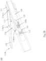
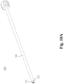
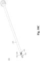
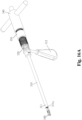
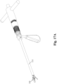
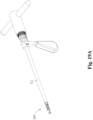
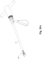
- FIG. 9A through FIG. 20C are schematic views of the operating tool.
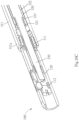
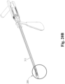
- FIG. 16A through FIG. 18B are schematic views of the operating tool and the spinal implant structure coupled thereto according to the first embodiment.
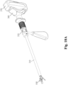
- FIG. 19A through FIG. 20C are schematic views of the operating tool and the spinal implant structure coupled thereto according to the second embodiment.
- FIG. 9A through FIG. 15A show that, although the operating tool connects with the spinal implant structure 100, the operating tool is also applicable to the spinal implant structure 200 in part or in full.
- the operating tool of the present invention comprises a tool body 310, a fixing (screw barrel / screw nut) sleeve 320, a central rod 330, an operating handle 340, a converter 350, a bone cement perfusing sleeve 360, and a bone cement ejector 370.
- the tool body 310, fixing (screw barrel / screw nut) sleeve 320, the central rod 330, operating handle 340, and converter 350 together constitute the operating tool whereby the spinal implant structure is expanded ( FIG. 16A through FIG. 17C show how the spinal implant structure 100 is folded/expanded; FIG. 19A through FIG.
- FIGs. 20C show how the spinal implant structure 200 is folded/expanded.
- the tool body 310, fixing (screw barrel / screw nut) sleeve 320, bone cement perfusing sleeve 360, and bone cement ejector 370 together constitute the tool for perfusing the bone cement upon completion of the expansion of the spinal implant structure 100 ( FIGs. 18A and 18B ).
- the tool body 310 serves as a carrier/connector for the operating tool and connects with the spinal implant structure 100.
- the tool body 310 comprises a connecting portion 311 and a gripping portion 312.
- the connecting portion 311 is a hollow-cored pipe and has a tail 311a.
- the tail 311a has a jointing structure which can be connected to the spinal implant structure 100 and fixed thereto integrally. This embodiment is exemplified by thread securing.
- the ways to couple the tool body 310 and the spinal implant structure 100 together include but are not limited to engagement and thread securing; hence, whatever jointing techniques will be applicable to the present invention, provided that the jointing techniques enable the tool body 310 and the spinal implant structure 100 to be firmly connected and easily disconnected.
- the gripping portion 312 is, for example, a handle to be gripped by a user or placed on another table/support to fix the kit in place.
- FIG. 10A through FIG. 10C wherein FIG. 10A and FIG. 10B show the fixing (screw barrel / screw nut) sleeve 320 which operates in conjunction with the spinal implant structure 100, and FIG. 10C shows the fixing (screw barrel / screw nut) sleeve 320 which operates in conjunction with the spinal implant structure 200.
- the fixing (screw barrel / screw nut) sleeve 320 is a hollow-cored pipe for fitting inside the tool body 310.
- the fixing (screw barrel / screw nut) sleeve 320 comprises a fixing screw barrel / screw nut 321 and a sleeve 322.
- the fixing screw barrel / screw nut 321 is specially designed (for example, its wall has an opening 323) to separate from the sleeve 322 when rotated and stay in the spinal implant structure 100, and then the sleeve 322 can be taken out of the spinal implant structure 100.
- the fixing screw nut 321 is disconnected from the fixing (screw barrel / screw nut) sleeve 320 to become a screw nut (i.e., a screw nut for fitting around a protruding part of the fixing screw barrel 120, as described before and shown in FIG. 1B ) of the spinal implant structure 100 in the first embodiment.
- a screw nut i.e., a screw nut for fitting around a protruding part of the fixing screw barrel 120, as described before and shown in FIG. 1B
- the fixing screw barrel 321 is disconnected from the fixing (screw barrel / screw nut) sleeve 320 to become the fixing screw barrel 220 ( FIG. 5B ) of the spinal implant structure 200 in the second embodiment.
- the fixing (screw nut / screw barrel) 321 disconnected from the fixing (screw barrel / screw nut) sleeve 320 is adapted to fix the distance between the first part 111, 211 and the second part 112, 212 in the spinal implant structure 100, 200.
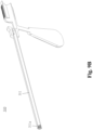
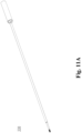
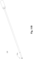
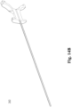
- FIG. 11A and 11B wherein FIG. 11A shows a central rod for use with the spinal implant structure 100, and FIG. 11B shows a central rod adapted for use with the spinal implant structure 100 and equipped with a connecting end 330a (left end).
- the central rod 330 is a slender rod for pulling and/or pushing the second part so as to effectuate the expansion of the spinal implant structure.
- the front end of the central rod 330 has a thread which matches the inner thread of the fixing screw barrel 120 of the spinal implant structure 100; hence, the front end of the central rod 330 can be insertedly fastened to the fixing screw barrel 120 and thus connected to the second part 112 of the spinal implant structure 100 through the fixing screw barrel 120 (as shown in FIG. 1B ).
- the thread matches the inner thread of the second part 212 of the spinal implant structure 200 and thus is directly, insertedly fastened to the second part 212 of the spinal implant structure 200 (as shown in FIG. 5B ).
- the operating handle 340 and the converter 350 drive the central rod 330 to move forward/backward so that the spinal implant structures 100, 200 are expanded or folded.
- the operating handle 340 operates by the principle of the lever whereby the user can exert a small force on the converter 350 by means of a long effort arm of the lever.
- the converter 350 converts the rotational torque exerted by the user into a horizontal, linear pushing/pulling force, so as to not only render the pushing/pulling force uniform but also reduce unnecessary vibration.
- the bone cement perfusing sleeve 360 and the bone cement ejector 370 are adapted to perfuse a bone cement, and their operation is illustrated by FIGs. (19 )18B, which show that their operation entails inserting the bone cement perfusing sleeve 360 directly into the fixing screw barrel (screw nut) 320, the tool body 310, and the spinal implant structure 100, filling the bone cement perfusing sleeve 360 with the bone cement, and finally pushing the bone cement into the spinal implant structure 100 with the bone cement ejector 370.
- the outer diameter of the bone cement ejector 370 substantially equals the inner diameter of the bone cement perfusing sleeve 360 in order for the bone cement to be pushed into the spinal implant structure 100.
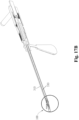
- FIG. 16A through FIG. 17C are schematic views of the operating tool and the spinal implant structure 100 coupled thereto.
- FIG. 16A through FIG. 16C are schematic views of the operating tool and the spinal implant structure 100 coupled thereto and folded.
- FIG. 17A through FIG. 17C are schematic views of the operating tool and the spinal implant structure 100 coupled thereto and expanded.
- FIG. 16C and FIG. 17C are partial enlarged views of the junction of the operating tool and the spinal implant structure.
- FIG. 16C the tail 311a of the connecting portion 311 of the tool body 310 is operated in a manner to be jointed to the first part 111 of the spinal implant structure 100.
- FIG. 16C is exemplified by thread jointing.
- the central rod 330 ( FIG. 11A ) is rotated and inserted into the fixing screw barrel 120.
- the operating handle 340 and converter 350 FIG. 17A , 17B ) are rotated, so as for the central rod 330 to be pulled backward, thereby effectuating the expansion of the spinal implant structure 100.
- the fixing screw barrel 120 upon completion of the expansion of the spinal implant structure 100, the fixing screw barrel 120 is at a location conducive to its operating the connecting portion 311 of the tool body 310; at this point in time, the user can move the fixing screw nut sleeve 320 ( FIGs. 10A , 10B ) of the operating tool leftward so that it fits around the fixing screw barrel 120 and thus gets fixed thereto.
- the fixing screw nut sleeve 320 After the fixing screw nut sleeve 320 has fitted around the fixing screw barrel 120, the user rotates it again in the same direction and applies a torque thereto, so as to separate the fixing screw nut 321 and the sleeve 322 and finish the fixation process.
- FIG. 19A through FIG. 20C are schematic views of the operating tool and the spinal implant structure 200 coupled thereto.
- FIG. 19A through FIG. 19C are schematic views of the operating tool and the spinal implant structure 200 coupled thereto and folded.
- FIG. 20A through FIG. 20C are schematic views of the operating tool and the spinal implant structure 200 coupled thereto and expanded.
- FIG. 19C and FIG. 20C are partial enlarged views of the junction of the operating tool and the spinal implant structure.
- the tail 311a of the connecting portion 311 of the tool body 310 is jointed to the first part 211 of the spinal implant structure 200 by engagement for exemplary sake.
- the central rod 330 ( FIG. 11B ) is rotated and inserted into the second part 212.
- the operating handle 340 and converter 350 FIGs.19A , 19B ) are rotated so as to push the central rod 330 forward, thereby effectuating the expansion of the spinal implant structure 200.
- the fixing screw barrel sleeve 320 FIG.
- the spinal implant structure is steadily expanded within the vertebral body. Furthermore, the design of the netting of the spinal implant structure restricts the range of the flow of the bone cement, reduces the likelihood of a failure of vertebroplasty, and reinforces the vertebral body as a result of the expansion of the spinal implant structure.
- the operating tool of the present invention comprises many components, the components are not only easily put together and separated but also embody plenty practical operation-related advantages.
- the user can easily disassemble the operating tool of the present invention and start to operate the spinal implant structure by hand so as to preclude any possible emergency. Therefore, the operating tool and the spinal implant structure of the present invention have advantages neither anticipated of nor achieved by conventional tools for use in vertebroplasty.
Landscapes
- Health & Medical Sciences (AREA)
- Orthopedic Medicine & Surgery (AREA)
- Life Sciences & Earth Sciences (AREA)
- Surgery (AREA)
- Neurology (AREA)
- Engineering & Computer Science (AREA)
- Biomedical Technology (AREA)
- Animal Behavior & Ethology (AREA)
- Public Health (AREA)
- Veterinary Medicine (AREA)
- Heart & Thoracic Surgery (AREA)
- General Health & Medical Sciences (AREA)
- Nuclear Medicine, Radiotherapy & Molecular Imaging (AREA)
- Molecular Biology (AREA)
- Medical Informatics (AREA)
- Transplantation (AREA)
- Cardiology (AREA)
- Oral & Maxillofacial Surgery (AREA)
- Vascular Medicine (AREA)
- Prostheses (AREA)
- Physical Education & Sports Medicine (AREA)
Description
- The present invention relates to spinal implant structures and, more particularly, to an intervertebral and intravertebral implant and a tool kit thereof.
- The spine, also known as the vertebral column, essentially comprises four types of elements, namely the spinal cord, vertebrae, ligaments, and intervertebral discs. Severe osteoporosis, intervertebral disc degeneration, ligament degeneration, joint dislocation, and joint compression may bring mechanical damage to the spine (such as a spinal compression fracture) and thus destabilize the spine. Spinal instability is accompanied by extreme discomfort and pain, thereby predisposing the patient to chronic back pain, spine curvature disorders, and walking disability.
- Among the ways to cure spinal instability is vertebroplasty, which entails placing an implant in a collapsed vertebral body. The implant in the collapsed vertebral body expands and thereby restores the collapsed vertebral body to its normal height. The implant is filled with a bone autograft or a bone substitute (bone cement) to enhance the stability of the spine with a view to curing spinal instability.
- A conventional spinal implant structure requires an implanting tool in order to be placed in the collapsed vertebral body and then expands. There is a wide variety of commercially available spinal implant structures and implanting tools. However, the prior art is unsatisfactory and thus still has room for improvement.
-
US 2002/068939 A1 relates to a device for stabilizing bone including a tubular body having first and second end regions defining a longitudinal axis therebetween. A plurality of splines extend from the first end region, the splines including first ends coupled the first end region, and second ends disposed away from the first end region, the second ends being directable from a generally axial collapsed state to a substantially transverse expanded state. A plurality of support arms are couples to the splines, and an actuator is coupled to the support arms, the actuator movable axially relative to the elongate body for causing the support arms to direct the second ends of the splines from the collapsed state to the expanded state. Optionally, the device includes another set of splines extending from the second end region or located at an intermediate region of the tubular body. - Further, a spinal implant structure is known from the
US 2005/278036 A1 , from which the preamble of claim 1 derives. - The present invention relates to a spinal implant structure as claimed hereafter. Preferred embodiments are set forth in the dependent claims.
- The present invention provides a spinal implant structure kit, comprising a spinal implant structure and an operating tool for use with the spinal implant structure. The spinal implant structure structurally matches the operating tool so that vertebroplasty can be performed efficiently and easily in terms of the adjustment of the position of the spinal implant structure, expansion of the vertebral body, and perfusion of a bone cement, etc.
- According to the present invention, a spinal implant structure is provided. The spinal implant structure comprises a first part, a second part, and at least one expansion arm. The second part is disposed along the lengthwise direction of the first part without overlapping the first part. The first part has a larger diameter than the second part. The at least one expansion arm has one end connecting with the first part and forming an included angle with the first part and the other end being a free end. The at least one expansion arm has a support arm. The support arm has one end connecting with the expansion arm and the other end connecting with the second part. The support arm comprises a plurality of weakened regions. In response to a change in the distance between the first part and the second part, the support arm bends at the weakened regions and thus drives the expansion arm to move, so as to increase the included angle and expand the spinal implant structure. The first part, second part, expansion arm, and support arm are formed integrally.
- In another embodiment of the present invention, a spinal implant kit comprises the spinal implant structure and the operating tool. The operating tool comprises a tool body, a fixing sleeve, a central rod, and an operating handle. The tool body has a connecting portion and a gripping portion. The connecting portion has a tail provided with a jointing structure for connecting with the spinal implant structure. The fixing sleeve fits inside the tool body to fix the distance between a first part and a second part of the spinal implant structure. The central rod fits inside the fixing sleeve to connect with the second part directly or connect with the second part through the fixing sleeve. The operating handle connects with the central rod and rotates to drive the central rod to move in the lengthwise direction of the first part.
- To render the above and other aspects of the present invention comprehensible, the present invention is hereunder illustrated by embodiments and accompanying drawings.
-
-
FIG. 1A through FIG. 4B are schematic views of a spinal implant structure according to an embodiment (first embodiment) of the present invention.FIG. 1A andFIG. 1B show that the spinal implant structure is folded (i.e., not netted).FIG. 2A through FIG. 2C show that the spinal implant structure (i.e., not netted) has been expanded.FIG. 3A andFIG. 3B show that the spinal implant structure (i.e., netted) is folded.FIG. 4A andFIG. 4B show that the spinal implant structure (i.e., netted) has been expanded. -
FIG. 5A through FIG. 8B are schematic views of the spinal implant structure according to another embodiment (second embodiment) of the present invention.FIG. 5A andFIG. 5B show that the spinal implant structure (i.e., not netted) is folded.FIG. 6A through FIG. 6C show that the spinal implant structure (i.e., not netted) has been expanded.FIG. 7A andFIG. 7B show that the spinal implant structure (i.e., netted) is folded.FIG. 8A through FIG. 8B show that the spinal implant structure (i.e., netted) has been expanded. -
FIG. 9A through FIG. 15A are schematic views of the operating tool, respectively. -
FIG. 16A through FIG. 18B are schematic views of the spinal implant structure and the operating tool coupled thereto according to the first embodiment of the present invention. -
FIG. 19A through FIG. 20C are schematic views of the spinal implant structure and the operating tool coupled thereto according to the second embodiment of the present invention. -
FIG. 21A through FIG. 21B are schematic views of the spinal implant structure according to yet another embodiment of the present invention. -
FIGs. 1A ,2A ,3A ,4A ,5A ,6A ,7A ,8A ,9A ,10A ,11A ,12A ,13A ,14A ,15A ,16A ,17A ,18A ,19A ,20A ,21A are lateral views.FIGs. 1B ,2B ,3B ,4B ,5B ,6B ,7B ,8B ,9B ,10B ,11B ,12B ,13B ,14B ,16B ,17B ,18B ,19B ,20B ,21B are cross-sectional views.FIGs. 2C ,6C ,10C ,16C ,17C ,19C ,20C are front views or partial enlarged views. - The aforesaid diagrams, which merely serve exemplary purposes to illustrate the shapes and relative positions of the constituent elements of the present invention, are not drawn to scale.
- Due to the limits of drawing software, a mark, for example, indicative of an anchor A or contact, may be shown in the aforesaid diagrams, but the anchor A or contact is optional rather than required.
- The present invention provides a spinal implant kit which comprises a spinal implant structure and an operating tool. The spinal implant structure is made of a metal or a biocompatible polymer. The metal includes a titanium alloy, whereas the biocompatible polymer includes polyether-ether-ketone (PEEK) and its derivatives. PEEK and cancellous bone are closely in hardness. Furthermore, carbon fiber reinforced PEEK, which is as hard as cortical bone, is applicable to the spinal implant kit of the present invention. However, the present invention is not restrictive of the materials which the spinal implant kit of the present invention is made of, and thus the spinal implant kit of the present invention may also be made of the other biocompatible materials.
-
FIG. 1A through FIG. 8C illustrate two different embodiments of a spinal implant structure of the present invention.FIG. 1A through FIG. 4B show aspinal implant structure 100 of the first embodiment of the present invention.FIG. 5A through FIG. 8C show aspinal implant structure 200 of the second embodiment of the present invention. - The
spinal implant structure 100, which is not netted, is illustrated byFIG. 1A through FIG. 2C . Referring toFIG. 1A andFIG. 1B , there are shown a lateral view and a cross-sectional view of thespinal implant structure 100 which is folded, respectively.FIG. 2A through FIG. 2C are a lateral view, a cross-sectional view, and a front view of thespinal implant structure 100 which has been expanded, respectively. Referring toFIGs.1A ,1B ,2A ,2B , thespinal implant structure 100 comprises abody 110 and a fixingscrew barrel 120. When thespinal implant structure 100 is folded, thebody 110 becomes a hollow-cored cylinder, and the fixingscrew barrel 120 also becomes a hollow-cored cylinder. Thespinal implant structure 100 has an expansion end 101 (left end) and a fixing end 102 (right end). Theexpansion end 101 is expanded with the operating tool (referring toFIG. 1A andFIG. 2A ), and the degree of expansion can be adjusted as needed. - The
body 110 of thespinal implant structure 100 comprises afirst part 111, asecond part 112, anexpansion arm 113, and asupport arm 114, and the four parts are formed integrally. Both thefirst part 111 and thesecond part 112 are hollow-cored cylinders. Thefirst part 111 and thesecond part 112, which are separated and do not overlap (engage), are arranged along the same horizontal axis (X-axis,FIG. 1B ). That is, thefirst part 111 and thesecond part 112 are two smaller independent tubes (which may also be called thefirst tube 111 and the second tube 112) split from thebody 110, and the two parts are connected by theexpansion arm 113 and the support arm 114.Thefirst part 111 contains the fixingscrew barrel 120. Thesecond part 112 contains a fixing component and a netting (to be described later.) Thefirst part 111 has an inner diameter slightly larger than thesecond part 112 and a length slightly longer than the length of thesecond part 112. The degree of the expansion of thespinal implant structure 100 can be changed by adjusting the distance between thefirst part 111 and thesecond part 112. In this embodiment, the degree of the expansion of thespinal implant structure 100 increases, as thefirst part 111 and thesecond part 112 get closer to thereby reduce the distance therebetween along the horizontal axis (X-axis). Hence, an operating tool (a central rod, to be described later) is required to draw thesecond part 112 closer to the first part 111 (i.e., rightward) in order for thespinal implant structure 100 to expand. - The bending of the
expansion arm 113 enables thespinal implant structure 100 to expand. Anend 113a (first end) of theexpansion arm 113 connects with thefirst part 111 and extends outward from thefirst part 111. Theother end 113b (second end) of theexpansion arm 113 is a free end which does not connect with any other component. A stress weakening portion (weakened section) is defined at a junction 113c of theexpansion arm 113 and thefirst part 111. The stress weakening portion is, for example, made thin or hollowed out so that the stress weakening portion (weakened section) is weaker than its surroundings. When subjected to an applied force, theexpansion arm 113 bends outward from the stress weakening portion to effectuate expansion. The stress weakening portion is a notch which may have a valley, a concave, a V-, a U-shape, etc. An included angle θ (shown inFIG. 2B ) smaller than 90 degrees is formed between theexpansion arm 113 and the extension line of thefirst part 111. The included angle θ indicates the degree of the expansion of thespinal implant structure 100. The included angle θ equals 0 degree when thespinal implant structure 100 is folded (FIG. 1A andFIG. 1B ). The included angle θ is larger than 0 degree but smaller than 90 degrees when thespinal implant structure 100 has been expanded (FIG. 2A andFIG. 2B ). Theexpansion arm 113 is in the number of one or more. If theexpansion arm 113 is in the number of two or more, theexpansion arms 113 connected to thefirst part 111 are equally spaced apart. As shown inFIG. 2C , in this embodiment, thespinal implant structure 100 comprises threeexpansion arms 113 spaced apart by 120 degrees. In another embodiment of the present invention, the expansion arms are in the number of two (and thus spaced apart by 180 degrees), four (and thus spaced apart by 90 degrees) or more. The more the expansion arms are provided, the more uniform the distribution of forces required to effectuate expansion is, the smaller each expansion arm is, and the stricter the requirement for product precision is. - The expansion arm 113 (expansion arm body) has therein a
support arm 114. Thesupport arm 114 is tongue-like in shape and can be considered as split from theexpansion arm 113; in other words, thesupport arm 114 and theexpansion arm 113 are formed integrally. Or, theexpansion arm 113 and thesupport arm 114 can both be considered as split from thebody 110. When thesupport arm 114 and theexpansion arm 113 are integrally formed and split from thebody 110, the manufacturing process of thespinal implant structure 100 can be further simplified. Anend 114a (first end) of thesupport arm 114 is not only connected to the inner side of theexpansion arm 113, but also connected to theexpansion arm 113 in a manner to be positioned proximate to thefirst part 111. Theother end 114b (second end) of thesupport arm 114 is connected to thesecond part 112 in a manner to be positioned proximate to thefirst part 111. At least one stress weakening portion (weakened section) is defined at thesupport arm 114. This embodiment is exemplified by two stress weakening portions located at a junction 114c of thesupport arm 114 and theexpansion arm 113 and a junction 114d of thesupport arm 114 and thesecond part 112, respectively. In response to a reduction in the distance between thefirst part 111 and thesecond part 112, thesupport arm 114 bends at the stress weakening portions under a force. As shown inFIG. 2B , at the stress weakening portion 114c, the support arm bends toward the inner side of thespinal implant structure 100, whereas, at the stress weakening portion 114d, thesupport arm 114 bends toward the outer side of thespinal implant structure 100, thereby driving theexpansion arm 113 to bend toward the outer side of thespinal implant structure 100 and thus increasing the included angle θ, so as for thespinal implant structure 100 to expand. The stress weakening portions are, for example, made thin or hollowed out so that the stress weakening portions are weaker than their surroundings; hence, when thesupport arm 114 is subjected to an applied force, the resultant stress is concentrated on the stress weakening portions, thereby causing structural deformation of the support arm 114 (i.e., the bending of the support arm 114). In the expansion process of thespinal implant structure 100, the distance between thefirst part 111 and thesecond part 112 decreases until the both parts meet. However, thefirst part 111 and thesecond part 112 do not overlap with or engage each other. - The
body 110 of thespinal implant structure 100 is preferably formed integrally, for example, by molding, lathing, milling, electrical discharge machining (EDM), 3D printing, or pressing, to form thefirst part 111, thesecond part 112, theexpansion arm 113, and thesupport arm 114 by a one-off process. - Like the
body 110, the fixingscrew barrel 120 is a hollow-cored cylinder. The fixingscrew barrel 120 fixes the distance between thefirst part 111 and thesecond part 112 upon completion of the expansion of thespinal implant structure 100. The fixingscrew barrel 120 has a smaller diameter than thefirst part 111 so as to fit inside thefirst part 111. The fixingscrew barrel 120 has an end positioned proximate to thesecond part 112, and the end has a protrudingportion 121. The diameter of the protrudingportion 121 substantially equals the inner diameter of thesecond part 112. The outer surface of the protrudingportion 121 has a firstouter thread 121a. The firstouter thread 121a matches a firstinner thread 112a disposed on the inner surface of thesecond part 112; hence, the protrudingportion 121 can be rotated and inserted into thesecond part 112 so as to be fixed thereto, allowing the fixingscrew barrel 120 to abuttingly connect with thesecond part 112. A secondinner thread 120a is disposed on the inner surface of the fixingscrew barrel 120. The secondinner thread 120a matches the outer thread (to be described later) of the central rod of the operating tool. After rotating and inserting the central rod into the fixing screw barrel, the user can pull the central rod and thereby drive the fixingscrew barrel 120 and thesecond part 112 to move, allowing thesecond part 112 to get closer to thefirst part 111, so as to effectuate the expansion of thespinal implant structure 100. - Referring to
FIG. 1B , when thespinal implant structure 100 is folded, the tail (right end) of the fixingscrew barrel 120 is contained in thefirst part 111. Referring toFIG. 2B , when thespinal implant structure 100 has been expanded, thesecond part 112 moves toward thefirst part 111, and the tail of the fixingscrew barrel 120 protrudes from thefirst part 111. Another screw nut (not shown, derived from the operating tool) fits around the protruding part of the tail of the fixingscrew barrel 120 to prevent the fixingscrew barrel 120 from moving toward thesecond part 112, thereby fixing the distance between thefirst part 111 and thesecond part 112. To fit the fixingscrew barrel 120 inside the other screw nut, an outer thread is disposed on a portion of the outer surface (tail) of the fixingscrew barrel 120. - The wall of the fixing
screw barrel 120 has one or at least two throughholes 122 whereby a bone cement enters the vertebral body during the bone cement perfusion step (to be described later). - When the
spinal implant structure 100 is in an expansion position (Fig. 2A ), it has a larger internal volume than when it is folded (Fig. 1A ), and can therefore support and restore a damaged/collapsed vertebral body; also, a large amount of bone cement can be filled in thespinal implant structure 100 to reinforce the support. -
FIG. 3A through FIG. 4B show that thespinal implant structure 100 has a netting 130 mounted thereon.FIG. 3A andFIG. 3B show that thespinal implant structure 100 is folded.FIG. 4A andFIG. 4B show that thespinal implant structure 100 has been expanded. The netting 130 restricts the range of flow of the bone cement being perfused into thespinal implant structure 100, so as to prevent the bone cement from spilling from the vertebral body, allow thespinal implant structure 100 to be uniformly expanded, and reinforce the vertebral body. - The netting 130 is hollow-cored and cylindrical in shape. The netting 130 fits around the
expansion arm 113 of thespinal implant structure 100 and can unfold as a result of the expansion of the spinal implant structure 100 (FIG. 4B ). The openings at the two ends of the netting 130 differ in size. The sidewall of the end with a larger opening has at least oneengaging hole 131. The end is engaged with a first part-facing end of theexpansion arm 113. The other end of the netting 130 has a fixinghole 132 of a smaller diameter (FIG. 4A ). When thespinal implant structure 100 is folded (FIG. 3B ), one end of the netting 130 is fixed to theexpansion arm 113 through the engaginghole 131, whereas the other end of the netting 130 is bent to be inserted into thespinal implant structure 100, and in consequence a fixingcomponent 140 is fixed to thesecond part 112 through the fixinghole 132. The fixingcomponent 140 is, for example, a screw whose thread enables it to be rotated and inserted into thesecond part 112. The outer diameter of the screw's head is slightly larger than the diameter of the fixinghole 132 of the netting 130. Hence, the netting 130 is fixed in place between the screw's head and thread; in other words, the netting 130 is fixed in place at the junction of thefixing component 140 and thesecond part 112. In this embodiment, the netting 130 is disconnectably engaged between the fixingcomponent 140 and thesecond part 112; hence, when thespinal implant structure 100 is expanded (FIGs.4A ,4B ), that is, at the time when thesecond part 112 moves toward thefirst part 111 under a pulling force, the netting 130 is disconnected from the fixingcomponent 140 under the pulling force, thereby allowing the netting 130 to unfold as a result of the expansion of thespinal implant structure 100. There are plenty of ways to disconnect the netting 130 from the fixingcomponent 140, including making the screw head of thefixing component 140 slightly larger than the fixinghole 132 and defining it with a lead angle, or providing several notches on the fixinghole 132, but the present invention is not limited thereto. Therefore, when thesecond part 112 moves toward thefirst part 111 under a pulling force, the netting 130 can be easily disconnected from the fixingcomponent 140 under a reverse pulling force. -
FIG. 5A through FIG. 6C show that thespinal implant structure 200 is not netted. Thespinal implant structure 200 of the second embodiment is identical to thespinal implant structure 100 of the first embodiment in terms of most technical features. For the sake of brevity, the identical technical features are not described herein. -
FIG. 5A andFIG. 5B are a lateral view and a cross-sectional view of thespinal implant structure 200 which is folded, respectively.FIG. 6A through FIG. 6C are a lateral view, a cross-sectional view, and a front view of thespinal implant structure 200 which has been expanded, respectively. Referring toFIGs. 5A ,5B ,6A ,6B , thespinal implant structure 200 comprises abody 210 and a fixingscrew barrel 220. When thespinal implant structure 200 is folded, thebody 210 is a hollow-cored cylinder, and the fixingscrew barrel 220 is also a hollow-cored cylinder. Thespinal implant structure 200 has an expansion end 201 (left end) and a fixing end 202 (right end). Theexpansion end 201 is expanded with the operating tool (shown inFIG. 5A andFIG. 6A ), and the degree of expansion can be adjusted as needed. - The
body 210 of thespinal implant structure 200 comprises afirst part 211, asecond part 212, anexpansion arm 213 and asupport arm 214, and the four parts are integrally formed. Both thefirst part 211 and thesecond part 212 are hollow-cored cylinders. Thefirst part 211 and thesecond part 212, which are separated and do not overlap, are arranged along the same horizontal axis (X-axis). That is, thefirst part 211 and thesecond part 212 can be considered as two smaller independent tubes split from thebody 210, and the two parts are connected by theexpansion arm 213 and thesupport arm 214. Thefirst part 211 contains the fixingscrew barrel 220. Thesecond part 212 contains a netting 230 and a fixing component 240 (FIG. 6A through FIG. 8B ). Thefirst part 211 has an internal diameter slightly larger than that of thesecond part 212. When thespinal implant structure 200 is folded, the distance between thefirst part 211 and thesecond part 212 is very short or the two parts even meet each other. The degree of the expansion of thespinal implant structure 200 can be changed by adjusting the distance between thefirst part 211 and thesecond part 212. The second embodiment differs from the first embodiment in that when thefirst part 211 and thesecond part 212 move away from each other, that is, the distance between thefirst part 211 and thesecond part 212 along the horizontal axis (X-axis) increases, the degree of expansion increases. In view of this, an operating tool (a central rod, to be described later) is required to move thesecond part 212 toward the expansion end 201 (i.e., leftward), so as to expand thespinal implant structure 200. - The
spinal implant structure 200 is expanded because of the bending of theexpansion arm 213. Theexpansion arm 213 has anend 213a (first end) which connects with thefirst part 211 and extends outward from thefirst part 211. Theother end 213b (second end) of theexpansion arm 213 is a free end which does not connect with any other component. A stress weakening portion(weakened section) is defined at a junction 213c of theexpansion arm 213 and thefirst part 211. The stress weakening portion is, for example, made thin or hollowed out so that the stress weakening portion (weakened section) is weaker than its surroundings. When subjected to an applied force, theexpansion arm 213 bends outward from the stress weakening portion to effectuate expansion. An included angle θ (FIG. 6B ) smaller than 90 degrees is formed between theexpansion arm 213 and the extension line of thefirst part 211. The included angle θ indicates the degree of the expansion of thespinal implant structure 200. The included angle θ equals 0 degree when thespinal implant structure 200 is folded (FIG. 5A andFIG. 5B ). The included angle θ is larger than 0 degree but smaller than 90 degrees when thespinal implant structure 200 has been expanded (FIG. 6A andFIG. 6B ). Theexpansion arm 213 is in the number of one or more. If theexpansion arm 213 is in the number of two or more, theexpansion arms 213 connected to thefirst part 211 are equally spaced apart. As shown inFIG. 6C , thespinal implant structure 200 comprises threeexpansion arms 213 spaced apart by 120 degrees. In another embodiment of the present invention, the expansion arms are in the number of two (and thus spaced apart by 180 degrees), four (and thus spaced apart by 90 degrees) or more. The more the expansion arms are provided, the more uniform the distribution of forces required to effectuate expansion is, the smaller each expansion arm is, and the stricter the requirement for product precision is. - The
expansion arm 213 has therein asupport arm 214. Thesupport arm 214 is tongue-like in shape and can be considered as formed by being split from theexpansion arm 213; in other words, thesupport arm 214 and theexpansion arm 213 are formed integrally. On the other hand, theexpansion arm 213 and thesupport arm 214 can both be considered as being split from thebody 210. Anend 214a (first end) of thesupport arm 214 is not only connected to the inner side of theexpansion arm 213, but also connected to theexpansion arm 213 in a manner to be positioned proximate to thefree end 213b. Theother end 214b (second end) of thesupport arm 214 is connected to thesecond part 112 in a manner to be positioned distal to thefirst part 211. At least one stress weakening portion (weakened region) is defined at thesupport arm 214. This embodiment is exemplified by two stress weakening portions located at a junction 214c of thesupport arm 214 and theexpansion arm 213 and a junction 214d of thesupport arm 214 and thesecond part 212, respectively. In response to an increase in the distance between thefirst part 211 and thesecond part 212, thesupport arm 214 bends at the stress weakening portions under a force. As shown inFIG. 6B , at the stress weakening portion 214c, thesupport arm 214 bends toward the inner side of thespinal implant structure 200, whereas, at the stress weakening portion 214d, thesupport arm 214 bends toward the outer side of thespinal implant structure 200, thereby driving theexpansion arm 213 to bend toward the outer side of thespinal implant structure 200 and thus increasing the included angle θ, so as for thespinal implant structure 200 to expand. The stress weakening portions are, for example, made thin or hollowed out so that the stress weakening portions are weaker than their surroundings; hence, when thesupport arm 214 is subjected to an applied force, the resultant stress is concentrated on the stress weakening portions, thereby causing structural deformation of the support arm 214 (i.e., the bending of the support arm 214). - Referring to
FIG. 21A andFIG. 21B , which illustrate aspinal implant structure 400 according to yet another embodiment of this invention. The difference between thespinal implant structure 400 and the above-describedspinal implant structure 200 lies in the design of a fixingend 402. As shown inFIG. 21A , an engagement positioning block 403 (the same design as in the spinal implant structure 200) is provided at the fixing end 402 (the left end) of thespinal implant structure 400, and is used to engage an operating tool described below. A corresponding engaging slot is provided at an engaging end of the operating tool for engaging thespinal implant structure 400. Anextension rib 404 is also provided on thespinal implant structure 400 and extends from theengagement positioning block 403 toward the inner side of the spinal implant structure 400 (i.e., toward the expansion arm 413). Theextension rib 404 is used for enhancing the strength of thefirst part 411 of thespinal implant structure 400, so that structural distortion or fracture can be avoided during the implanting process. Besides, as shown inFIG. 21B , theengagement positioning block 403 can extend slightly more toward the outer (left) side of thespinal implant structure 400 and have an extraouter protruding block 403A extending out from the fixingend 402 of thespinal implant structure 400. When thespinal implant structure 400 comprises the outer protrudingblock 403A, it can more steadily connect with or engage an operating tool (as will be described later) having a corresponding slot or recess structure, and the occurrence of sliding or displacement in the implanting process can be reduced. In yet another embodiment of this invention, arecess 405 can be arranged at the inner side of abody 410 of thespinal implant structure 400. Therecess 405 connects to the outside of thebody 410, and has an opening in a horizontal direction (X-axis) of thefirst part 411. Therecess 405 can be a long concaved slot or groove, and as therecess 405 has one opening end and another closed end, an auxiliary tool (such as a long and thin rod or needle) can be used to reach into therecess 405 from the outside of thebody 410 to further apply a force by pressing against therecess 405. As such, when withdrawing the operating tool, the force applying thereto can be increased without causing displacement of thespinal implant structure 400, thereby solving the problem of distortion during the implanting process that hampers withdrawal of the operating tool. - Like the
body 210, the fixingscrew barrel 220 is a hollow-cored cylinder. The fixingscrew barrel 220 fixes the distance between thefirst part 211 and thesecond part 212 upon completion of the expansion of thespinal implant structure 200. The fixingscrew barrel 220 has a smaller diameter than thefirst part 211 so as to fit inside thefirst part 211. A third outer thread is disposed on a portion of the outer surface of the fixingscrew barrel 220. The third outer thread matches a third inner thread disposed on the inner surface of thefirst part 211. Hence, the fixingscrew barrel 220 can be rotated and inserted into thefirst part 211, so as to be adjustably moved forward and backward by the threads and fixed in place. Since the position of the fixingscrew barrel 220 is adjustable, the front end of the fixingscrew barrel 220 can abuttingly connect with thesecond part 212 so that thesecond part 212 is fixed in place, thereby fixing the distance between thefirst part 211 and thesecond part 212. Since the fixingscrew barrel 220 is adjustably moved forward and backward by the threads, it generates a torque. As a result, thespinal implant structure 200 in operation does not require the fixingscrew barrel 220 to move thesecond part 212; instead, a central rod (to be described later) of the operating tool moves thesecond part 212 horizontally away from thefirst part 211 and thus effectuates the expansion of thespinal implant structure 200, and then the fixingscrew barrel 220 is moved forward to abuttingly connect with thesecond part 212, thereby fixing thesecond part 212 in place. - Referring to
FIG. 5B , when thespinal implant structure 200 is folded, the tail of the fixingscrew barrel 220 protrudes from thefirst part 211 slightly. Referring toFIG. 6B , when thespinal implant structure 200 has been expanded, thesecond part 212 separates from thefirst part 211 to allow the tail of the fixingscrew barrel 220 to enter thefirst part 211 completely and allow the front end of the fixingscrew barrel 220 to abuttingly connect with thesecond part 211, thereby fixing the distance between thefirst part 211 and thesecond part 212. - The wall of the fixing
screw barrel 220 has one or at least two throughholes 222 whereby the bone cement enters the vertebral body during the bone cement perfusion step (to be described later). -
FIG. 7A through FIG. 8B show that thespinal implant structure 200 has a netting 230 mounted thereon.FIG. 7A andFIG. 7B show that thespinal implant structure 200 is folded.FIG. 8A andFIG. 8B show that thespinal implant structure 200 has been expanded. The netting 230 restricts the range of flow of the bone cement being perfused into thespinal implant structure 200, so as to prevent the bone cement from spilling from the vertebral body, allow thespinal implant structure 200 to be uniformly expanded, and reinforce the vertebral body. - The netting 230 is hollow-cored and cylindrical in shape. The netting 230 fits around the
expansion arm 213 of thespinal implant structure 200 and can unfold as a result of the expansion of the spinal implant structure 200 (FIG. 8B ). The openings at the two ends of the netting 230 differ in size. The sidewall of the end with a larger opening has at least oneengaging hole 231. The end is engaged with a first part-facing end of theexpansion arm 213. The other end of the netting 230 has a fixinghole 232 of a smaller diameter (FIG. 8A ). When thespinal implant structure 200 is folded (FIG. 7B ), one end of the netting 230 is fixed to theexpansion arm 213 through the engaginghole 231, whereas the other end of the netting 230 is bent to be inserted into thespinal implant structure 200, and in consequence the fixingcomponent 240 is fixed to thesecond part 212 through the fixinghole 232. The fixingcomponent 240 is, for example, a screw whose thread enables it to be rotated and inserted into thesecond part 212. The outer diameter of the screw's head is slightly larger than the diameter of the fixinghole 232 of the netting 230. Hence, the netting 230 is fixed in place between the screw's head and thread; in other words, the netting 230 is fixed in place at the junction of thefixing component 240 and thesecond part 212. The second embodiment differs from the first embodiment in that the netting 230 of thespinal implant structure 200 is steadily engaged between the fixingcomponent 240 and thesecond part 212 without getting disconnected, and thus when thespinal implant structure 200 is expanded (FIGs. 8A ,8B ), that is, at the time when thesecond part 212 moves toward theexpansion end 101 under a pushing force and thus moves away from thefirst part 211, the netting 230 unfolds as a result of the expansion of thespinal implant structure 200. - The spinal implant structure of the present invention operates in conjunction with an operating tool in order to perform precise operations, such as implantation, expansion, and bone cement perfusion. Embodiments of the operating tool of the present invention are illustrated by
FIG. 9A through FIG. 20C .FIG. 9A through FIG. 15A are schematic views of the operating tool.FIG. 16A through FIG. 18B are schematic views of the operating tool and the spinal implant structure coupled thereto according to the first embodiment.FIG. 19A through FIG. 20C are schematic views of the operating tool and the spinal implant structure coupled thereto according to the second embodiment.FIG. 9A through FIG. 15A show that, although the operating tool connects with thespinal implant structure 100, the operating tool is also applicable to thespinal implant structure 200 in part or in full. Persons skilled in the art understand that although the operating tool of the present invention varies slightly in structure and shape, depending on whether it is applied to thespinal implant structure 100 or thespinal implant structure 200, the variations in structure and shape of the operating tool are designed in accordance with operational concepts and relationships disclosed according to the present invention and thus fall within the scope of the present invention. - Referring to
FIG. 9A through 15A , the operating tool of the present invention comprises atool body 310, a fixing (screw barrel / screw nut)sleeve 320, acentral rod 330, anoperating handle 340, aconverter 350, a bonecement perfusing sleeve 360, and abone cement ejector 370. Thetool body 310, fixing (screw barrel / screw nut)sleeve 320, thecentral rod 330, operatinghandle 340, andconverter 350 together constitute the operating tool whereby the spinal implant structure is expanded (FIG. 16A through FIG. 17C show how thespinal implant structure 100 is folded/expanded;FIG. 19A through FIG. 20C show how thespinal implant structure 200 is folded/expanded.) Thetool body 310, fixing (screw barrel / screw nut)sleeve 320, bonecement perfusing sleeve 360, andbone cement ejector 370 together constitute the tool for perfusing the bone cement upon completion of the expansion of the spinal implant structure 100 (FIGs. 18A and18B ). - Referring to
FIGs. 9A and9B , thetool body 310 serves as a carrier/connector for the operating tool and connects with thespinal implant structure 100. Thetool body 310 comprises a connectingportion 311 and agripping portion 312. The connectingportion 311 is a hollow-cored pipe and has atail 311a. Thetail 311a has a jointing structure which can be connected to thespinal implant structure 100 and fixed thereto integrally. This embodiment is exemplified by thread securing. The ways to couple thetool body 310 and thespinal implant structure 100 together include but are not limited to engagement and thread securing; hence, whatever jointing techniques will be applicable to the present invention, provided that the jointing techniques enable thetool body 310 and thespinal implant structure 100 to be firmly connected and easily disconnected. The grippingportion 312 is, for example, a handle to be gripped by a user or placed on another table/support to fix the kit in place. - Referring to
FIG. 10A through FIG. 10C , whereinFIG. 10A andFIG. 10B show the fixing (screw barrel / screw nut)sleeve 320 which operates in conjunction with thespinal implant structure 100, andFIG. 10C shows the fixing (screw barrel / screw nut)sleeve 320 which operates in conjunction with thespinal implant structure 200. The fixing (screw barrel / screw nut)sleeve 320 is a hollow-cored pipe for fitting inside thetool body 310. For example, the fixing (screw barrel / screw nut)sleeve 320 comprises a fixing screw barrel /screw nut 321 and asleeve 322. The fixing screw barrel /screw nut 321 is specially designed (for example, its wall has an opening 323) to separate from thesleeve 322 when rotated and stay in thespinal implant structure 100, and then thesleeve 322 can be taken out of thespinal implant structure 100. Referring toFIG. 10A , the fixingscrew nut 321 is disconnected from the fixing (screw barrel / screw nut)sleeve 320 to become a screw nut (i.e., a screw nut for fitting around a protruding part of the fixingscrew barrel 120, as described before and shown inFIG. 1B ) of thespinal implant structure 100 in the first embodiment. Referring toFIG. 10C , the fixingscrew barrel 321 is disconnected from the fixing (screw barrel / screw nut)sleeve 320 to become the fixing screw barrel 220 (FIG. 5B ) of thespinal implant structure 200 in the second embodiment. The fixing (screw nut / screw barrel) 321 disconnected from the fixing (screw barrel / screw nut)sleeve 320 is adapted to fix the distance between thefirst part second part spinal implant structure - Referring to
FIG. 11A and11B , whereinFIG. 11A shows a central rod for use with thespinal implant structure 100, andFIG. 11B shows a central rod adapted for use with thespinal implant structure 100 and equipped with a connectingend 330a (left end). Thecentral rod 330 is a slender rod for pulling and/or pushing the second part so as to effectuate the expansion of the spinal implant structure. The front end of thecentral rod 330 has a thread which matches the inner thread of the fixingscrew barrel 120 of thespinal implant structure 100; hence, the front end of thecentral rod 330 can be insertedly fastened to the fixingscrew barrel 120 and thus connected to thesecond part 112 of thespinal implant structure 100 through the fixing screw barrel 120 (as shown inFIG. 1B ). Alternatively, the thread matches the inner thread of thesecond part 212 of thespinal implant structure 200 and thus is directly, insertedly fastened to thesecond part 212 of the spinal implant structure 200 (as shown inFIG. 5B ). - Referring to
FIG. 12A through 13B , theoperating handle 340 and theconverter 350 drive thecentral rod 330 to move forward/backward so that thespinal implant structures operating handle 340 operates by the principle of the lever whereby the user can exert a small force on theconverter 350 by means of a long effort arm of the lever. Theconverter 350 converts the rotational torque exerted by the user into a horizontal, linear pushing/pulling force, so as to not only render the pushing/pulling force uniform but also reduce unnecessary vibration. - Referring to
FIG. 14A through 15A , the bonecement perfusing sleeve 360 and thebone cement ejector 370 are adapted to perfuse a bone cement, and their operation is illustrated byFIGs. (19 )18B, which show that their operation entails inserting the bonecement perfusing sleeve 360 directly into the fixing screw barrel (screw nut) 320, thetool body 310, and thespinal implant structure 100, filling the bonecement perfusing sleeve 360 with the bone cement, and finally pushing the bone cement into thespinal implant structure 100 with thebone cement ejector 370. Hence, the outer diameter of thebone cement ejector 370 substantially equals the inner diameter of the bonecement perfusing sleeve 360 in order for the bone cement to be pushed into thespinal implant structure 100. -
FIG. 16A through FIG. 17C are schematic views of the operating tool and thespinal implant structure 100 coupled thereto.FIG. 16A through FIG. 16C are schematic views of the operating tool and thespinal implant structure 100 coupled thereto and folded.FIG. 17A through FIG. 17C are schematic views of the operating tool and thespinal implant structure 100 coupled thereto and expanded.FIG. 16C andFIG. 17C are partial enlarged views of the junction of the operating tool and the spinal implant structure. - Referring to
FIG. 16C , thetail 311a of the connectingportion 311 of thetool body 310 is operated in a manner to be jointed to thefirst part 111 of thespinal implant structure 100.FIG. 16C is exemplified by thread jointing. The central rod 330 (FIG. 11A ) is rotated and inserted into the fixingscrew barrel 120. Then, theoperating handle 340 and converter 350 (FIG. 17A ,17B ) are rotated, so as for thecentral rod 330 to be pulled backward, thereby effectuating the expansion of thespinal implant structure 100. Referring toFIG. 17C , upon completion of the expansion of thespinal implant structure 100, the fixingscrew barrel 120 is at a location conducive to its operating the connectingportion 311 of thetool body 310; at this point in time, the user can move the fixing screw nut sleeve 320 (FIGs. 10A ,10B ) of the operating tool leftward so that it fits around the fixingscrew barrel 120 and thus gets fixed thereto. After the fixingscrew nut sleeve 320 has fitted around the fixingscrew barrel 120, the user rotates it again in the same direction and applies a torque thereto, so as to separate the fixingscrew nut 321 and thesleeve 322 and finish the fixation process. -
FIG. 19A through FIG. 20C are schematic views of the operating tool and thespinal implant structure 200 coupled thereto.FIG. 19A through FIG. 19C are schematic views of the operating tool and thespinal implant structure 200 coupled thereto and folded.FIG. 20A through FIG. 20C are schematic views of the operating tool and thespinal implant structure 200 coupled thereto and expanded.FIG. 19C andFIG. 20C are partial enlarged views of the junction of the operating tool and the spinal implant structure. - Referring to
FIG. 19C , thetail 311a of the connectingportion 311 of thetool body 310 is jointed to thefirst part 211 of thespinal implant structure 200 by engagement for exemplary sake. The central rod 330 (FIG. 11B ) is rotated and inserted into thesecond part 212. Then, theoperating handle 340 and converter 350 (FIGs.19A ,19B ) are rotated so as to push thecentral rod 330 forward, thereby effectuating the expansion of thespinal implant structure 200. After thesecond part 212 has been pushed forward and fixed in place to effectuate the expansion of thespinal implant structure 200, as shown inFIG. 20C , the fixing screw barrel sleeve 320 (FIG. 10C ) rotates and moves forward so that the front end of the fixingscrew barrel sleeve 320 abuttingly connects with thesecond part 212 to fix it in place. At this point in time, the user rotates the fixingscrew barrel sleeve 320 again in the same direction and applies a torque thereto, so as to separate the fixingscrew barrel 321 and thesleeve 322, keep the fixingscrew barrel 321, finish the fixation process, and remove thesleeve 322. - Due to the design of the expansion arm and the support arm of the spinal implant structure of the present invention, the spinal implant structure is steadily expanded within the vertebral body. Furthermore, the design of the netting of the spinal implant structure restricts the range of the flow of the bone cement, reduces the likelihood of a failure of vertebroplasty, and reinforces the vertebral body as a result of the expansion of the spinal implant structure.
- Due to the design of the connection of the operating tool and the spinal implant structure of the present invention, not only are the spinal implant structure and the operating tool coupled together, but the expansion step and the bone cement perfusion step are also stable, thereby increasing the likelihood of successful vertebroplasty and reducing complications.
- Although the operating tool of the present invention comprises many components, the components are not only easily put together and separated but also embody plenty practical operation-related advantages. When necessary, the user can easily disassemble the operating tool of the present invention and start to operate the spinal implant structure by hand so as to preclude any possible emergency. Therefore, the operating tool and the spinal implant structure of the present invention have advantages neither anticipated of nor achieved by conventional tools for use in vertebroplasty.
Claims (16)
- A spinal implant structure (100; 200; 400) having a folded position and an expansion position, comprising:
a body (110; 210; 410), the body (110; 210; 410) being a hollow-cored cylinder when the spinal implant structure (100; 200; 400) is in the folded position, the body (110; 210; 410) comprising:a first part (111; 211; 411);a second part (112; 212), the second part (112; 212) not overlapping the first part (111; 211; 411); andat least one expansion arm (113; 213; 413); andat least one support arm (114; 214), the support arm (114; 214) having an end connecting with the expansion arm (113; 213; 413) and another end connecting with the second part (112; 212),wherein the first part (111; 211; 411), the second part (112; 212), the expansion arm (113; 213; 413), and the support arm (114; 214) are formed integrally, andwherein the spinal implant structure (100: 200; 400) is designed to be implanted within a vertebral body,
characterized in thatthe expansion arm (113; 213; 413) having an end connecting with the first part (111; 211; 411) and another end being not coupled to the support arm (114; 214) to be a free end;wherein the support arm (114; 214) comprises a plurality of weakened sections so that, in response to a change in a distance between the first part (111; 211; 411) and the second part (112; 212), the support arm (114; 214) bends at the weakened sections and thus drives the expansion arm (113; 213; 413) to move, thereby increasing an included angle between the expansion arm (113; 213; 413) and the first part (111; 211; 411), expanding the spinal implant structure (100; 200; 400), and causing the spinal implant structure (100; 200; 400) to turn into the expansion position. - The spinal implant structure (100; 200; 400) of claim 1, wherein the number of the expansion arm (113; 213; 413) is at least three, and the expansion arms (113; 213; 413) connected to the first part (111; 211; 411) are equally spaced apart.
- The spinal implant structure (100; 200; 400) of claim 1, wherein the included angle between the expansion arm (113; 213; 413) and the first part (111; 211; 411) increases as the distance between the first part (111; 211; 411) and the second part (112; 212) increases.
- The spinal implant structure (100; 200; 400) of claim 1, wherein the included angle between the expansion arm (113; 213; 413) and the first part (111; 211; 411) decreases as the distance between the first part (111; 211; 411) and the second part (112; 212) decreases.
- The spinal implant structure (100; 200; 400) of claim 1, further comprising:a fixing screw barrel (120; 220) fitting inside the first part (111; 211; 411) and having an end abuttingly connecting with the second part (112; 212) to fix the distance between the first part (111; 211; 411) andthe second part (112; 212).
- The spinal implant structure (100; 200; 400) of claim 5, wherein a wall of the fixing screw barrel (120; 220) has at least one through hole (122; 222) for perfusing a bone cement.
- The spinal implant structure (100; 200; 400) of claim 1, wherein the weakened sections are V-shaped or concave notches.
- The spinal implant structure (100; 200; 400) of claim 1, further comprising:
a netting (130; 230), wherein an end of the netting (130; 230) has at least one engaging hole (131; 231) whereby the end of the netting (130; 230) is engaged with the at least one expansion arm (113; 213; 413), and another end of the netting (130; 230) is fixed to the second part (112; 212) through a fixing component (140; 240) so that the netting (130; 230) fits around an outer surface of the expansion arm (113; 213; 413), allowing the netting (130; 230) to be unfolded as a result of the expansion of the spinal implant structure (100; 200; 400). - The spinal implant structure (100; 200; 400) of claim 8, wherein the netting (130; 230) separates from the fixing component (140; 240) as a result of the expansion of the spinal implant structure (100; 200; 400).
- The spinal implant structure (100; 200; 400) of claim 1, wherein the first part (111; 211; 411) having an inner diameter larger than that of the second part (112; 212).
- The spinal implant structure (100; 200; 400) of claim 1, wherein the expansion arm (113; 213; 413) and the support arm (114; 214) are split from the body (110; 210; 410).
- The spinal implant structure (100; 200; 400) of claim 1, wherein the spinal implant structure (100; 200; 400) has a larger volume in the expansion position than in the folded position.
- The spinal implant structure (100; 200; 400) of claim 1, wherein the body (110; 210; 410) comprises at least one engagement positioning block (403) and at least one extension rib (404), the extension rib (404) extending from the engagement positioning block (403) toward the expansion arm (113; 213; 413) to enhance strength of the first part (111; 211; 411).
- The spinal implant structure (100; 200; 400) of claim 13, wherein the engagement positioning block (403) comprises an outer protruding block (403A) extending toward an outer side beyond the body (110; 210; 410).
- A spinal implant kit, comprising:the spinal implant structure (100; 200; 400) of claim 1; andan operating tool, comprising:a tool body (310) comprising a connecting portion (311) and a gripping portion (312), the connecting portion (311) having a tail (311a) provided with a jointing structure for connecting with the spinal implant structure (100; 200; 400);a fixing sleeve fitting inside the tool body (310) to fix a distance between the first part (111; 211; 411) and the second part (112; 212) of the spinal implant structure (100; 200; 400);a central rod (330) fitting inside the fixing sleeve (320) to connect with the second part (112; 212) directly or connect with the second part (112; 212) through the fixing sleeve (320); andan operating handle (340) connecting with the central rod (330) and rotating to drive the central rod (330) to move in a lengthwise direction of the first part (111; 211; 411).
- The spinal implant kit of claim 15, further comprising:a bone cement perfusing sleeve (360) fitting inside the fixing sleeve (320) and the spinal implant structure (100; 200; 400) to provide a path for perfusing a bone cement into the spinal implant structure (100; 200; 400); anda bone cement ejector (370) fitting inside the bone cement perfusing sleeve (360) to push the bone cement into the spinal implant structure (100; 200; 400).
Applications Claiming Priority (2)
| Application Number | Priority Date | Filing Date | Title |
|---|---|---|---|
| TW105107739A TWI589266B (en) | 2016-03-14 | 2016-03-14 | Spinal implant structure and kit thereof |
| EP17160573.6A EP3219273B1 (en) | 2016-03-14 | 2017-03-13 | Spinal implant structure and kit thereof |
Related Parent Applications (2)
| Application Number | Title | Priority Date | Filing Date |
|---|---|---|---|
| EP17160573.6A Division-Into EP3219273B1 (en) | 2016-03-14 | 2017-03-13 | Spinal implant structure and kit thereof |
| EP17160573.6A Division EP3219273B1 (en) | 2016-03-14 | 2017-03-13 | Spinal implant structure and kit thereof |
Publications (3)
| Publication Number | Publication Date |
|---|---|
| EP3708099A1 EP3708099A1 (en) | 2020-09-16 |
| EP3708099C0 EP3708099C0 (en) | 2023-08-09 |
| EP3708099B1 true EP3708099B1 (en) | 2023-08-09 |
Family
ID=58277214
Family Applications (2)
| Application Number | Title | Priority Date | Filing Date |
|---|---|---|---|
| EP20161601.8A Active EP3708099B1 (en) | 2016-03-14 | 2017-03-13 | Spinal implant structure and kit thereof |
| EP17160573.6A Active EP3219273B1 (en) | 2016-03-14 | 2017-03-13 | Spinal implant structure and kit thereof |
Family Applications After (1)
| Application Number | Title | Priority Date | Filing Date |
|---|---|---|---|
| EP17160573.6A Active EP3219273B1 (en) | 2016-03-14 | 2017-03-13 | Spinal implant structure and kit thereof |
Country Status (4)
| Country | Link |
|---|---|
| US (2) | US10555820B2 (en) |
| EP (2) | EP3708099B1 (en) |
| CN (2) | CN110916784A (en) |
| TW (1) | TWI589266B (en) |
Families Citing this family (17)
| Publication number | Priority date | Publication date | Assignee | Title |
|---|---|---|---|---|
| US9545283B2 (en) * | 2013-12-23 | 2017-01-17 | Jmea Corporation | Devices and methods for preparation of vertebral members |
| US11253369B2 (en) * | 2016-03-14 | 2022-02-22 | Wiltrom Co., Ltd. | Spinal implant structure and kit thereof |
| TWI589266B (en) * | 2016-03-14 | 2017-07-01 | 曾昌和 | Spinal implant structure and kit thereof |
| US10512495B2 (en) | 2017-12-28 | 2019-12-24 | Industrial Technology Research Institute | Method for fabricating medical device and applications thereof |
| TWI652037B (en) | 2017-12-28 | 2019-03-01 | 財團法人工業技術研究院 | Expandable orthopedic implant |
| TWI649062B (en) * | 2018-04-26 | 2019-02-01 | 台灣微創醫療器材股份有限公司 | Spinal reaming device |
| TWI720677B (en) * | 2019-11-05 | 2021-03-01 | 台灣微創醫療器材股份有限公司 | Spinal implant structure |
| TWI711424B (en) * | 2019-11-06 | 2020-12-01 | 台灣微創醫療器材股份有限公司 | Operating tool for spinal implant |
| CN112842496A (en) * | 2019-11-27 | 2021-05-28 | 柏力科技股份有限公司 | Triangular connecting rod type vertebra distraction device |
| TWI752390B (en) * | 2019-12-18 | 2022-01-11 | 柏力科技股份有限公司 | Trumpet expandable vertebral device |
| US11337824B2 (en) * | 2019-12-20 | 2022-05-24 | Globus Medical, Inc. | Stabilizing vertebrae with articulating implants |
| CN113040839A (en) * | 2019-12-27 | 2021-06-29 | 柏力科技股份有限公司 | Expansion type vertebra distraction device |
| CN111134912A (en) * | 2020-01-22 | 2020-05-12 | 宁波华科润生物科技有限公司 | Percutaneous intervertebral fusion system |
| TWI725830B (en) * | 2020-04-28 | 2021-04-21 | 台灣微創醫療器材股份有限公司 | Operating tool for spinal exapndable implant |
| CN112089509B (en) * | 2020-07-24 | 2022-11-11 | 钱卫庆 | Integration interbody treatment fuses ware |
| CN112120778B (en) * | 2020-09-17 | 2022-03-25 | 山东冠龙医疗用品有限公司 | Centrum struts filling device and propeller |
| WO2022132583A1 (en) * | 2020-12-18 | 2022-06-23 | Spine Wave, Inc. | Expandable tlif device and related insertion and grafting instrumentation |
Family Cites Families (32)
| Publication number | Priority date | Publication date | Assignee | Title |
|---|---|---|---|---|
| FR2715293B1 (en) * | 1994-01-26 | 1996-03-22 | Biomat | Vertebral interbody fusion cage. |
| FR2753368B1 (en) * | 1996-09-13 | 1999-01-08 | Chauvin Jean Luc | EXPANSIONAL OSTEOSYNTHESIS CAGE |
| US6554833B2 (en) | 1998-10-26 | 2003-04-29 | Expanding Orthopedics, Inc. | Expandable orthopedic device |
| US6814756B1 (en) * | 2000-02-04 | 2004-11-09 | Gary K. Michelson | Expandable threaded arcuate interbody spinal fusion implant with lordotic configuration during insertion |
| US6443989B1 (en) * | 2000-12-04 | 2002-09-03 | Roger P. Jackson | Posterior expandable fusion cage |
| US6773460B2 (en) * | 2000-12-05 | 2004-08-10 | Roger P. Jackson | Anterior variable expandable fusion cage |
| US7128760B2 (en) * | 2001-03-27 | 2006-10-31 | Warsaw Orthopedic, Inc. | Radially expanding interbody spinal fusion implants, instrumentation, and methods of insertion |
| US20030220650A1 (en) * | 2002-03-18 | 2003-11-27 | Major Eric D. | Minimally invasive bone manipulation device and method of use |
| US6955691B2 (en) * | 2003-11-21 | 2005-10-18 | Kyungwon Medical Co., Ltd. | Expandable interfusion cage |
| US7507241B2 (en) * | 2004-04-05 | 2009-03-24 | Expanding Orthopedics Inc. | Expandable bone device |
| FR2871366A1 (en) * | 2004-06-09 | 2005-12-16 | Ceravic Soc Par Actions Simpli | PROSTHETIC EXPANSIBLE BONE IMPLANT |
| US7678148B2 (en) * | 2004-07-23 | 2010-03-16 | Warsaw Orthopedic, Inc. | Expandable spinal implant having interlocking geometry for structural support |
| US7655046B2 (en) * | 2005-01-20 | 2010-02-02 | Warsaw Orthopedic, Inc. | Expandable spinal fusion cage and associated instrumentation |
| US8034080B2 (en) * | 2005-02-17 | 2011-10-11 | Kyphon Sarl | Percutaneous spinal implants and methods |
| US9801733B2 (en) * | 2005-03-31 | 2017-10-31 | Life Spine, Inc. | Expandable spinal interbody and intravertebral body devices |
| CN100340215C (en) * | 2005-09-19 | 2007-10-03 | 吴乃庆 | Bone dilator |
| US7879098B1 (en) * | 2005-10-19 | 2011-02-01 | Simmons Jr James W | Expandable lordosis stabilizing cage |
| WO2009125242A1 (en) * | 2008-04-08 | 2009-10-15 | Vexim | Apparatus for restoration of the spine and methods of use thereof |
| EP2376730A2 (en) * | 2008-12-31 | 2011-10-19 | Omar F. Jimenez | Flexible joint arrangement incorporating flexure members |
| WO2010105174A1 (en) | 2009-03-12 | 2010-09-16 | Expanding Orthopedics, Inc. | Bone implantation and stabilization assembly including deployment device |
| US8157842B2 (en) * | 2009-06-12 | 2012-04-17 | Kyphon Sarl | Interspinous implant and methods of use |
| US8894712B2 (en) * | 2010-01-11 | 2014-11-25 | Innova Spinal Technologies, Llc | Expandable intervertebral implant and associated surgical method |
| US8685095B2 (en) * | 2011-04-19 | 2014-04-01 | Warsaw Orthopedic, Inc. | Expandable implant system and methods of use |
| US9907671B2 (en) * | 2012-11-16 | 2018-03-06 | In Queue Innovations, Llc | Oblique expanding fusion cage device and method |
| WO2014144696A1 (en) * | 2013-03-15 | 2014-09-18 | Lanx, Inc. | Expandable fusion cage system |
| CN104116579B (en) * | 2013-04-28 | 2016-08-03 | 苏州海欧斯医疗器械有限公司 | Implantation unit is strutted between a kind of Via Posterior Spinal Approach ridge |
| US10265192B2 (en) * | 2013-07-03 | 2019-04-23 | Spine Innovation, Llc | Methods and apparatus for implanting an interbody device |
| CN105011993B (en) | 2014-04-17 | 2018-06-01 | 思必瑞特脊椎股份有限公司 | Bone anchoring device |
| WO2016077610A1 (en) * | 2014-11-12 | 2016-05-19 | Grotz Robert Thomas | Universally expanding cage |
| US9814602B2 (en) * | 2015-05-14 | 2017-11-14 | Globus Medical, Inc. | Expandable intervertebral implants and methods of installation thereof |
| US11291555B2 (en) * | 2015-10-01 | 2022-04-05 | Asfora Ip, Llc | Vertebral cage |
| TWI589266B (en) * | 2016-03-14 | 2017-07-01 | 曾昌和 | Spinal implant structure and kit thereof |
-
2016
- 2016-03-14 TW TW105107739A patent/TWI589266B/en active
-
2017
- 2017-03-13 EP EP20161601.8A patent/EP3708099B1/en active Active
- 2017-03-13 EP EP17160573.6A patent/EP3219273B1/en active Active
- 2017-03-13 US US15/457,020 patent/US10555820B2/en active Active
- 2017-03-14 CN CN201911290621.7A patent/CN110916784A/en active Pending
- 2017-03-14 CN CN201710150597.1A patent/CN107184263B/en active Active
-
2020
- 2020-01-08 US US16/737,152 patent/US11395745B2/en active Active
Also Published As
| Publication number | Publication date |
|---|---|
| TW201731464A (en) | 2017-09-16 |
| US11395745B2 (en) | 2022-07-26 |
| CN107184263A (en) | 2017-09-22 |
| EP3219273B1 (en) | 2021-01-20 |
| EP3708099C0 (en) | 2023-08-09 |
| EP3708099A1 (en) | 2020-09-16 |
| US20170258600A1 (en) | 2017-09-14 |
| CN107184263B (en) | 2020-06-12 |
| CN110916784A (en) | 2020-03-27 |
| US10555820B2 (en) | 2020-02-11 |
| US20200138590A1 (en) | 2020-05-07 |
| TWI589266B (en) | 2017-07-01 |
| EP3219273A1 (en) | 2017-09-20 |
Similar Documents
| Publication | Publication Date | Title |
|---|---|---|
| EP3708099B1 (en) | Spinal implant structure and kit thereof | |
| US11253369B2 (en) | Spinal implant structure and kit thereof | |
| JP5847289B2 (en) | Expandable orthopedic device | |
| US10813771B2 (en) | Methods and apparatuses for bone restoration | |
| US20210069584A1 (en) | Unitarily formed expandable spinal implant and method of manufafturing and implanting same | |
| TWI581755B (en) | Vertebral expandable implant, expandable implant and method for testoring a space between two surfaces | |
| AU2020264273B2 (en) | Spinal implant structure | |
| JP2022527837A (en) | Multi-axis surgical screws and devices for embedding the surgical screws | |
| MXPA00001242A (en) | Intervertebral implant whereof the parts can be spaced |
Legal Events
| Date | Code | Title | Description |
|---|---|---|---|
| PUAI | Public reference made under article 153(3) epc to a published international application that has entered the european phase |
Free format text: ORIGINAL CODE: 0009012 |
|
| STAA | Information on the status of an ep patent application or granted ep patent |
Free format text: STATUS: THE APPLICATION HAS BEEN PUBLISHED |
|
| AC | Divisional application: reference to earlier application |
Ref document number: 3219273 Country of ref document: EP Kind code of ref document: P |
|
| AK | Designated contracting states |
Kind code of ref document: A1 Designated state(s): AL AT BE BG CH CY CZ DE DK EE ES FI FR GB GR HR HU IE IS IT LI LT LU LV MC MK MT NL NO PL PT RO RS SE SI SK SM TR |
|
| STAA | Information on the status of an ep patent application or granted ep patent |
Free format text: STATUS: REQUEST FOR EXAMINATION WAS MADE |
|
| 17P | Request for examination filed |
Effective date: 20210316 |
|
| RBV | Designated contracting states (corrected) |
Designated state(s): AL AT BE BG CH CY CZ DE DK EE ES FI FR GB GR HR HU IE IS IT LI LT LU LV MC MK MT NL NO PL PT RO RS SE SI SK SM TR |
|
| GRAP | Despatch of communication of intention to grant a patent |
Free format text: ORIGINAL CODE: EPIDOSNIGR1 |
|
| STAA | Information on the status of an ep patent application or granted ep patent |
Free format text: STATUS: GRANT OF PATENT IS INTENDED |
|
| INTG | Intention to grant announced |
Effective date: 20230328 |
|
| GRAS | Grant fee paid |
Free format text: ORIGINAL CODE: EPIDOSNIGR3 |
|
| GRAA | (expected) grant |
Free format text: ORIGINAL CODE: 0009210 |
|
| STAA | Information on the status of an ep patent application or granted ep patent |
Free format text: STATUS: THE PATENT HAS BEEN GRANTED |
|
| AC | Divisional application: reference to earlier application |
Ref document number: 3219273 Country of ref document: EP Kind code of ref document: P |
|
| AK | Designated contracting states |
Kind code of ref document: B1 Designated state(s): AL AT BE BG CH CY CZ DE DK EE ES FI FR GB GR HR HU IE IS IT LI LT LU LV MC MK MT NL NO PL PT RO RS SE SI SK SM TR |
|
| REG | Reference to a national code |
Ref country code: GB Ref legal event code: FG4D |
|
| REG | Reference to a national code |
Ref country code: CH Ref legal event code: EP |
|
| REG | Reference to a national code |
Ref country code: DE Ref legal event code: R096 Ref document number: 602017072671 Country of ref document: DE |
|
| REG | Reference to a national code |
Ref country code: IE Ref legal event code: FG4D |
|
| U01 | Request for unitary effect filed |
Effective date: 20230814 |
|
| U07 | Unitary effect registered |
Designated state(s): AT BE BG DE DK EE FI FR IT LT LU LV MT NL PT SE SI Effective date: 20230818 |
|
| PG25 | Lapsed in a contracting state [announced via postgrant information from national office to epo] |
Ref country code: GR Free format text: LAPSE BECAUSE OF FAILURE TO SUBMIT A TRANSLATION OF THE DESCRIPTION OR TO PAY THE FEE WITHIN THE PRESCRIBED TIME-LIMIT Effective date: 20231110 |
|
| PG25 | Lapsed in a contracting state [announced via postgrant information from national office to epo] |
Ref country code: IS Free format text: LAPSE BECAUSE OF FAILURE TO SUBMIT A TRANSLATION OF THE DESCRIPTION OR TO PAY THE FEE WITHIN THE PRESCRIBED TIME-LIMIT Effective date: 20231209 |
|
| PG25 | Lapsed in a contracting state [announced via postgrant information from national office to epo] |
Ref country code: RS Free format text: LAPSE BECAUSE OF FAILURE TO SUBMIT A TRANSLATION OF THE DESCRIPTION OR TO PAY THE FEE WITHIN THE PRESCRIBED TIME-LIMIT Effective date: 20230809 Ref country code: NO Free format text: LAPSE BECAUSE OF FAILURE TO SUBMIT A TRANSLATION OF THE DESCRIPTION OR TO PAY THE FEE WITHIN THE PRESCRIBED TIME-LIMIT Effective date: 20231109 Ref country code: IS Free format text: LAPSE BECAUSE OF FAILURE TO SUBMIT A TRANSLATION OF THE DESCRIPTION OR TO PAY THE FEE WITHIN THE PRESCRIBED TIME-LIMIT Effective date: 20231209 Ref country code: HR Free format text: LAPSE BECAUSE OF FAILURE TO SUBMIT A TRANSLATION OF THE DESCRIPTION OR TO PAY THE FEE WITHIN THE PRESCRIBED TIME-LIMIT Effective date: 20230809 Ref country code: GR Free format text: LAPSE BECAUSE OF FAILURE TO SUBMIT A TRANSLATION OF THE DESCRIPTION OR TO PAY THE FEE WITHIN THE PRESCRIBED TIME-LIMIT Effective date: 20231110 |
|
| PG25 | Lapsed in a contracting state [announced via postgrant information from national office to epo] |
Ref country code: PL Free format text: LAPSE BECAUSE OF FAILURE TO SUBMIT A TRANSLATION OF THE DESCRIPTION OR TO PAY THE FEE WITHIN THE PRESCRIBED TIME-LIMIT Effective date: 20230809 |
|
| PG25 | Lapsed in a contracting state [announced via postgrant information from national office to epo] |
Ref country code: ES Free format text: LAPSE BECAUSE OF FAILURE TO SUBMIT A TRANSLATION OF THE DESCRIPTION OR TO PAY THE FEE WITHIN THE PRESCRIBED TIME-LIMIT Effective date: 20230809 |
|
| PG25 | Lapsed in a contracting state [announced via postgrant information from national office to epo] |
Ref country code: SM Free format text: LAPSE BECAUSE OF FAILURE TO SUBMIT A TRANSLATION OF THE DESCRIPTION OR TO PAY THE FEE WITHIN THE PRESCRIBED TIME-LIMIT Effective date: 20230809 Ref country code: RO Free format text: LAPSE BECAUSE OF FAILURE TO SUBMIT A TRANSLATION OF THE DESCRIPTION OR TO PAY THE FEE WITHIN THE PRESCRIBED TIME-LIMIT Effective date: 20230809 Ref country code: ES Free format text: LAPSE BECAUSE OF FAILURE TO SUBMIT A TRANSLATION OF THE DESCRIPTION OR TO PAY THE FEE WITHIN THE PRESCRIBED TIME-LIMIT Effective date: 20230809 Ref country code: CZ Free format text: LAPSE BECAUSE OF FAILURE TO SUBMIT A TRANSLATION OF THE DESCRIPTION OR TO PAY THE FEE WITHIN THE PRESCRIBED TIME-LIMIT Effective date: 20230809 Ref country code: SK Free format text: LAPSE BECAUSE OF FAILURE TO SUBMIT A TRANSLATION OF THE DESCRIPTION OR TO PAY THE FEE WITHIN THE PRESCRIBED TIME-LIMIT Effective date: 20230809 |
|
| U20 | Renewal fee paid [unitary effect] |
Year of fee payment: 8 Effective date: 20240402 |