EP3708086A1 - Information processing apparatus, learning device, and program - Google Patents
Information processing apparatus, learning device, and program Download PDFInfo
- Publication number
- EP3708086A1 EP3708086A1 EP20162444.2A EP20162444A EP3708086A1 EP 3708086 A1 EP3708086 A1 EP 3708086A1 EP 20162444 A EP20162444 A EP 20162444A EP 3708086 A1 EP3708086 A1 EP 3708086A1
- Authority
- EP
- European Patent Office
- Prior art keywords
- unit
- failure
- defective pixel
- radiography
- time
- Prior art date
- Legal status (The legal status is an assumption and is not a legal conclusion. Google has not performed a legal analysis and makes no representation as to the accuracy of the status listed.)
- Granted
Links
Images

Classifications
-
- A—HUMAN NECESSITIES
- A61—MEDICAL OR VETERINARY SCIENCE; HYGIENE
- A61B—DIAGNOSIS; SURGERY; IDENTIFICATION
- A61B6/00—Apparatus or devices for radiation diagnosis; Apparatus or devices for radiation diagnosis combined with radiation therapy equipment
- A61B6/42—Arrangements for detecting radiation specially adapted for radiation diagnosis
- A61B6/4208—Arrangements for detecting radiation specially adapted for radiation diagnosis characterised by using a particular type of detector
- A61B6/4233—Arrangements for detecting radiation specially adapted for radiation diagnosis characterised by using a particular type of detector using matrix detectors
-
- A—HUMAN NECESSITIES
- A61—MEDICAL OR VETERINARY SCIENCE; HYGIENE
- A61B—DIAGNOSIS; SURGERY; IDENTIFICATION
- A61B6/00—Apparatus or devices for radiation diagnosis; Apparatus or devices for radiation diagnosis combined with radiation therapy equipment
- A61B6/58—Testing, adjusting or calibrating thereof
- A61B6/586—Detection of faults or malfunction of the device
-
- A—HUMAN NECESSITIES
- A61—MEDICAL OR VETERINARY SCIENCE; HYGIENE
- A61B—DIAGNOSIS; SURGERY; IDENTIFICATION
- A61B6/00—Apparatus or devices for radiation diagnosis; Apparatus or devices for radiation diagnosis combined with radiation therapy equipment
- A61B6/58—Testing, adjusting or calibrating thereof
- A61B6/582—Calibration
-
- G—PHYSICS
- G01—MEASURING; TESTING
- G01T—MEASUREMENT OF NUCLEAR OR X-RADIATION
- G01T7/00—Details of radiation-measuring instruments
- G01T7/005—Details of radiation-measuring instruments calibration techniques
-
- G—PHYSICS
- G06—COMPUTING OR CALCULATING; COUNTING
- G06N—COMPUTING ARRANGEMENTS BASED ON SPECIFIC COMPUTATIONAL MODELS
- G06N20/00—Machine learning
-
- G—PHYSICS
- G06—COMPUTING OR CALCULATING; COUNTING
- G06N—COMPUTING ARRANGEMENTS BASED ON SPECIFIC COMPUTATIONAL MODELS
- G06N7/00—Computing arrangements based on specific mathematical models
- G06N7/01—Probabilistic graphical models, e.g. probabilistic networks
-
- G—PHYSICS
- G16—INFORMATION AND COMMUNICATION TECHNOLOGY [ICT] SPECIALLY ADAPTED FOR SPECIFIC APPLICATION FIELDS
- G16H—HEALTHCARE INFORMATICS, i.e. INFORMATION AND COMMUNICATION TECHNOLOGY [ICT] SPECIALLY ADAPTED FOR THE HANDLING OR PROCESSING OF MEDICAL OR HEALTHCARE DATA
- G16H30/00—ICT specially adapted for the handling or processing of medical images
- G16H30/20—ICT specially adapted for the handling or processing of medical images for handling medical images, e.g. DICOM, HL7 or PACS
-
- G—PHYSICS
- G16—INFORMATION AND COMMUNICATION TECHNOLOGY [ICT] SPECIALLY ADAPTED FOR SPECIFIC APPLICATION FIELDS
- G16H—HEALTHCARE INFORMATICS, i.e. INFORMATION AND COMMUNICATION TECHNOLOGY [ICT] SPECIALLY ADAPTED FOR THE HANDLING OR PROCESSING OF MEDICAL OR HEALTHCARE DATA
- G16H40/00—ICT specially adapted for the management or administration of healthcare resources or facilities; ICT specially adapted for the management or operation of medical equipment or devices
- G16H40/40—ICT specially adapted for the management or administration of healthcare resources or facilities; ICT specially adapted for the management or operation of medical equipment or devices for the management of medical equipment or devices, e.g. scheduling maintenance or upgrades
-
- G—PHYSICS
- G16—INFORMATION AND COMMUNICATION TECHNOLOGY [ICT] SPECIALLY ADAPTED FOR SPECIFIC APPLICATION FIELDS
- G16H—HEALTHCARE INFORMATICS, i.e. INFORMATION AND COMMUNICATION TECHNOLOGY [ICT] SPECIALLY ADAPTED FOR THE HANDLING OR PROCESSING OF MEDICAL OR HEALTHCARE DATA
- G16H40/00—ICT specially adapted for the management or administration of healthcare resources or facilities; ICT specially adapted for the management or operation of medical equipment or devices
- G16H40/60—ICT specially adapted for the management or administration of healthcare resources or facilities; ICT specially adapted for the management or operation of medical equipment or devices for the operation of medical equipment or devices
- G16H40/63—ICT specially adapted for the management or administration of healthcare resources or facilities; ICT specially adapted for the management or operation of medical equipment or devices for the operation of medical equipment or devices for local operation
-
- A—HUMAN NECESSITIES
- A61—MEDICAL OR VETERINARY SCIENCE; HYGIENE
- A61B—DIAGNOSIS; SURGERY; IDENTIFICATION
- A61B6/00—Apparatus or devices for radiation diagnosis; Apparatus or devices for radiation diagnosis combined with radiation therapy equipment
- A61B6/50—Apparatus or devices for radiation diagnosis; Apparatus or devices for radiation diagnosis combined with radiation therapy equipment specially adapted for specific body parts; specially adapted for specific clinical applications
- A61B6/502—Apparatus or devices for radiation diagnosis; Apparatus or devices for radiation diagnosis combined with radiation therapy equipment specially adapted for specific body parts; specially adapted for specific clinical applications for diagnosis of breast, i.e. mammography
Definitions
- the present invention relates to an information processing apparatus, a learning device, and a program that use a radiographic image captured using radiation such as X-rays.
- the radiography apparatus comprises a radiography unit such as a flat panel detector (FPD).
- the FPD has an imaging region in which a plurality of pixels that accumulate signal charge corresponding to the amount of incident radiation are arranged.
- the defective pixel correction is performed by detecting the positional information of a defective pixel of the FPD and correcting the defective pixel using the image data of pixels around the defective pixel in a case in which a radiographic image is displayed.
- JP2011-072417A discloses a method that predicts the lifetime of a radiography unit using an FPD from the positional information of a defective pixel. Specifically, first, the size (the number of pixels) of the pixel defect is calculated and registered in a defect information table. Then, the change characteristics (for example, a linear equation) of a pixel defect are calculated by an operation from the defect information table which has been registered in time series and the time when the pixel defect reaches the upper limit (the size of the pixel defect at which the radiography unit needs to be replaced) is calculated as the lifetime on the basis of the change characteristics.
- the change characteristics for example, a linear equation
- the size of the pixel defect is 1.
- pixels adjacent to the primitive defective pixel become the defective pixels and the number of defective pixels is added. The added value is recognized as the size of the pixel defect.
- the actual deterioration of the radiography unit changes due to not only one parameter, such as the size of the pixel defect, but also several factors, such as the density of defective pixels and the number of defective pixels.
- the change characteristics of the pixel defect are only calculated from the size of the pixel defect registered in time series. Therefore, in the method disclosed in JP2011-072417A , it is difficult to predict the failure of the radiography unit with high accuracy.
- An object of the invention is to provide an information processing apparatus, a learning device, and a program that can predict the failure of a radiography unit with high accuracy.
- An information processing apparatus comprises a defective pixel map data acquisition unit and a failure condition estimation unit.
- the defective pixel map data acquisition unit acquires defective pixel map data indicating positional information of a defective pixel which is defective among a plurality of pixels forming a radiography unit.
- the failure condition estimation unit estimates a failure probability of the radiography unit or a usage state of the radiography unit at the time of failure, using a learned model that receives the defective pixel map data and outputs the failure probability of the radiography unit or the usage state of the radiography unit at the time of failure.
- the information processing apparatus further comprises a notification unit that sets a threshold value corresponding to the failure probability or the usage state at the time of failure estimated by the failure condition estimation unit and performs notification in a case in which the failure probability or the usage state at the time of failure is greater than the threshold value.
- the defective pixel map data acquisition unit acquires a calibration image output from the radiography unit as the defective pixel map data.
- the failure probability is a probability that the radiography unit will be out of order within a preset time.
- the usage state at the time of failure is a time until the radiography unit is out of order, the number of images captured until the radiography unit is out of order, or the number of times a high voltage is applied to the radiography unit until the radiography unit is out of order.
- a learning device comprises a learning data acquisition unit, a learning unit, and an evaluation function update unit.
- the learning unit uses an evaluation function updated by the evaluation function update unit.
- the learning data acquisition unit acquires learning data in which defective pixel map data indicating positional information of a defective pixel which is defective among a plurality of pixels forming a radiography unit is associated with a recording value of a failure probability of the radiography unit or a usage state of the radiography unit at the time of failure.
- the learning unit calculates an evaluation value of the failure probability or the usage state at the time of failure from the defective pixel map data using an evaluation function.
- the evaluation function update unit updates the evaluation function, using an error between the evaluation value of the failure probability or the usage state at the time of failure calculated by the learning unit using the evaluation function and the recording value of the failure probability or the usage state at the time of failure in the learning data, in a case in which the learning data is acquired.
- the failure probability is a probability that the radiography unit will be out of order within a preset time.
- the usage state at the time of failure is the number of images captured until the radiography unit is out of order after the use of the radiography unit starts or the number of times a high voltage is applied to the radiography unit until the radiography unit is out of order.
- any one of the number of images captured until the radiography unit is out of order after the defective pixel map data is acquired, a time until the radiography unit is out of order after the defective pixel map data is acquired, or an imaging frequency of the radiography unit per predetermined time, the defective pixel map data, and the recording value of the failure probability of the radiography unit or the usage state of the radiography unit at the time of failure are associated with each other.
- a program drives an information processing apparatus comprising a defective pixel map data acquisition unit that acquires defective pixel map data indicating positional information of a defective pixel which is defective among a plurality of pixels forming a radiography unit.
- the program causes the information processing apparatus to perform: estimating a failure probability of the radiography unit or a usage state of the radiography unit at the time of failure, using a learned model that receives the defective pixel map data and outputs the failure probability of the radiography unit or the usage state of the radiography unit at the time of failure.
- a mammography apparatus 10 which is an example of a radiography apparatus comprises an apparatus main body 11 that captures an image of the breast of a subject using X-rays which are radiation and a console 12 that controls the apparatus main body 11.
- the apparatus main body 11 and the console 12 are connected wirelessly or in a wired manner and transmit and receive data and control signals therebetween if necessary.
- the apparatus main body 11 comprises, for example, a support 31, an X-ray generation unit 32, an imaging table 33, a compression plate 36, and an elevating unit 37.
- the X-ray generation unit 32 and the imaging table 33 are integrated to form a movable unit 40 whose position is adjusted according to the subject in the apparatus main body 11.
- the X-ray generation unit 32 includes at least an X-ray tube that generates X-rays. Therefore, in the mammography apparatus 10, the X-ray generation unit 32 is a radiation generation unit that generates radiation (X-rays). In addition, the X-ray generation unit 32 may include a high voltage circuit that supplies a high voltage for generating X-rays to an X-ray tube. That is, the X-ray generation unit 32 may be configured by a so-called mono-tank.
- the imaging table 33 is a stage on which the breast is placed and the breast is interposed between the imaging table 33 and the compression plate 36 during imaging.
- the imaging table 33 forms a radiography unit that captures the image of the breast of the subject using radiation (X-rays).
- the imaging table 33 includes, as the radiography unit, an FPD 41 (see Fig. 3 ) that captures the image of the breast using radiation and a grid that removes scattered radiation (a stationary Lysholm Blende or a mobile Bucky Blende).
- the mammography apparatus 10 may have a plurality of kinds of grids that can be replaced according to imaging conditions and may perform imaging using the grids.
- a gripping portion 34a that is gripped by the right hand of the subject and a gripping portion 34b that is gripped by the left hand of the subject are attached to the imaging table 33.
- the gripping portion 34a and the gripping portion 34b are so-called armrests. Since X-rays are used in this embodiment, the radiography unit is specifically an X-ray imaging unit.
- the compression plate 36 compresses and flattens the breast of the subject placed on the imaging table 33 during imaging. This is to reduce the overlap of the normal mammary glands and to easily find the candidates of a lesion such as calcification.
- the elevating unit 37 moves up and down the compression plate 36 with respect to the imaging table 33.
- the elevating unit 37 supports the compression plate 36 substantially in parallel to the imaging table 33 at a specific distance corresponding to the thickness of the breast.
- the movable unit 40 is rotatable in a predetermined angle range while maintaining the relative position and direction of the X-ray generation unit 32 and the imaging table 33. Therefore, the apparatus main body 11 can perform imaging in a state in which the imaging table 33 is horizontally disposed or the imaging table 33 is disposed obliquely with respect to the horizontal direction. Specifically, the apparatus main body 11 can perform craniocaudal imaging (CC imaging) in which the imaging table 33 is horizontally disposed and the image of the breast is captured in a craniocaudal direction. Further, the apparatus main body 11 can perform mediolateral oblique imaging (MLO imaging) in which the imaging table 33 is obliquely disposed and the image of the breast is captured in a mediolateral oblique direction.
- CC imaging craniocaudal imaging
- MLO imaging mediolateral oblique imaging
- the X-ray generation unit 32 is rotatable in a predetermined range while the position of the imaging table 33 and the compression plate 36 is fixed. Therefore, the apparatus main body 11 can perform so-called stereo imaging and tomosynthesis imaging.
- the stereo imaging is an imaging aspect that captures the image of the breast of the subject, which is fixed at a specific position and in a specific direction (for example, the position and direction in the CC imaging), from one direction or a plurality of oblique directions with different inclination angles to obtain a perspective image (hereinafter, referred to as a stereo image) from the oblique direction.
- the tomosynthesis imaging is an imaging aspect that captures the images of the breast of the subject, which is fixed at a specific position and in a specific direction, from a plurality of oblique directions and obtains a tomographic image (hereinafter, referred to as a tomosynthesis image) of the breast of the subject using the captured images.
- the FPD 41 as the X-ray imaging unit comprises a conversion panel 42, a scanning driving unit 43, a reading unit 44, an FPD control unit 45, an analog/digital (A/D) converter 46, a memory 47, and a communication unit 48.
- the conversion panel 42 has an imaging region 50 in which a plurality of pixels 49 that accumulate signal charge corresponding to the amount of incident X-rays are two-dimensionally arranged.
- the plurality of pixels 49 are arranged at a predetermined pitch in a matrix of G1 to Gn rows (X direction) and D1 to Dm columns (Y direction).
- the two-dimensional array of the pixels may be a square array as in this embodiment or may be a honeycomb array.
- the conversion panel 42 is, for example, a direct conversion type that directly converts X-rays into charge and accumulates signal charge (a first example of an electric signal).
- amorphous selenium is used as an X-ray conversion film.
- a thin film transistor (TFT) 51, a capacitor (not illustrated) for accumulating signal charge, and a pixel electrode 52 for defining a pixel 49 are formed on an insulating substrate such as a glass substrate.
- the X-ray conversion film is formed on the TFT 51 and the pixel electrode 52 in the entire surface of the imaging region 50 and a common electrode is formed on the X-ray conversion film.
- the X-rays are converted into charge by the X-ray conversion film and signal charge is accumulated in each pixel 49 through the pixel electrode 52.
- the signal charge accumulated in the pixel 49 is read by the TFT 51.
- the TFT 51 has a gate electrode connected to a scanning line 53, a source electrode connected to a signal line 54, and a drain electrode connected to the capacitor of the pixel 49.
- the scanning lines 53 and the signal lines 54 are arranged in a lattice shape.
- the number of scanning lines 53 provided is equal to the number of rows (n rows) of the pixels 49 and the number of signal lines 54 provided is equal to the number of columns (m columns) of the pixels 49 in the imaging region 50.
- the scanning line 53 is connected to the scanning driving unit 43 and the signal line 54 is connected to the reading unit 44.
- the reading unit 44 includes an integration amplifier that converts the signal charge read from the conversion panel 42 into a voltage signal and a multiplexer that sequentially switches the columns of the pixels 49 in the imaging region 50 and sequentially outputs the voltage signals corresponding to each column.
- the reading unit 44 outputs the read voltage signal as an image signal to the A/D converter 46.
- the A/D converter 46 converts the image signal into digital data and writes the digital data into the memory 47 so as to be associated with coordinates indicating the position of the pixel 49 in the imaging region 50.
- the FPD control unit 45 transmits the digital image signal in the memory 47 as an X-ray image to the console 12 through the wireless or wired communication unit 48.
- the mammography apparatus 10 performs defect correction calibration in addition to the capture of a general X-ray image.
- the defect correction calibration is calibration accompanied by X-ray irradiation.
- the defect correction calibration is a calibration for acquiring defect correction data 61A and defective pixel map data which will be described below and is performed during periodic maintenance, in addition to during product shipment and installation. This is because the number of defective pixels change over time.
- the periodic maintenance is performed once a day on the day when X-ray imaging is performed using the mammography apparatus 10.
- imaging is performed in a state in which the movable unit 40 is set to the direction and position corresponding to all types of imaging performed by the mammography apparatus 10, such as CC imaging and MLO imaging, to acquire a calibration image.
- the calibration image is an image acquired during defect correction calibration involving X-ray irradiation.
- the calibration image is generated by the FPD control unit 45 on the basis of the image signal output from the conversion panel 42. Since there is no subject, the entire surface of the imaging region 50 of the conversion panel 42 is uniformly irradiated with X-rays. Therefore, the sensitivity characteristics of each pixel 49 or the information of a defective pixel is reflected in the calibration image.
- the FPD control unit 45 transmits an image signal of the calibration image written into the memory 47 to the console 12 through the communication unit 48.
- the calibration image is an image obtained by emitting X-rays
- a defect caused by the defective pixel occurs in the calibration image.
- alphabet D indicates a defective pixel.
- the defective pixel D is a pixel that is not sensitive to incident X-rays and does not generate charge, a pixel that generates change whose amount does not reach a reference range, or a pixel that generates change whose amount is more than the reference range.
- a defect appears as a black spot or a white spot.
- the defective pixel D is represented by a black spot.
- a plurality of defective pixels D occur in adjacent regions and the density of the defective pixels in the entire imaging region is higher than that in the non-failure state.
- the size of the defect varies depending on the number of defective pixels.
- the console 12 is a control device that controls the mammography apparatus 10 and an information processing apparatus that processes information using various mammography images. As illustrated in Fig. 4 , the console 12 comprises an image processing unit 61, a defective pixel map data acquisition unit 62, a failure condition estimation unit 63, a notification unit 64, and a display unit 65.
- the image processing unit 61 performs various kinds of correction for the X-ray image on the basis of, for example, preset correction data. In this embodiment, the image processing unit 61 performs defect correction on the basis of the defect correction data 61A.
- the display unit 65 displays the X-ray image processed by the image processing unit 61.
- the image processing unit 61 creates the defect correction data 61A on the basis of the calibration image acquired during the defect correction calibration of the conversion panel 42.
- the defect correction data 61A is data for correcting abnormal data which is generated in the X-ray image due to the defective pixel among the pixels 49 of the conversion panel 42.
- the X-ray image in which abnormal data has been corrected is obtained by defect correction using the defect correction data 61A. Specifically, the defect correction is performed by interpolation based on the data of normal pixels around the defective pixel.
- the calibration image is used to create the defect correction data 61A in the image processing unit 61 and is used as the defective pixel map data in the failure condition estimation unit 63.
- the defective pixel map data acquisition unit 62 controls the X-ray generation unit 32 and the imaging table 33 (FPD 41) to acquire the calibration image (defective pixel map data).
- the failure condition estimation unit 63 receives the defective pixel map data acquired by the defective pixel map data acquisition unit 62 and estimates the failure probability of the FPD 41 and the usage state of the FPD 41 at the time of failure.
- the failure condition estimation unit 63 may be configured by a learned model (a so-called artificial intelligence (AI) program) that receives the defective pixel map data and outputs the failure probability or the usage state at the time of failure which is estimated in a case in which the subsequent imaging is performed using the FPD 41.
- AI artificial intelligence
- the failure probability is the probability that the FPD 41 will be out of order within a preset time.
- the usage state at the time of failure is the time until the FPD 41 is out of order, the number of images captured until the FPD 41 is out of order, or the number of times a high voltage is applied to the FPD 41 until the FPD 41 is out of order.
- the radiography unit that detects radiation using an X-ray conversion film, such as an FPD needs to apply a high voltage of several kilovolts (kV) (2 kV in the case of the FPD) in order to form an electric field for moving electrons and holes generated by the incidence of radiation in a case in which the apparatus starts up and during periodic maintenance.
- kV kilovolts
- the state of the defect changes with the lapse of time since the application of the high voltage. That is, as the number of times the high voltage is applied becomes larger, the probability of failure becomes higher and the state of the apparatus becomes closer to a failure state.
- the failure condition estimation unit 63 uses learning data, in which the defective pixel map data actually acquired from the FPD 41 in the failure state is associated with the actual failure probability (100%), the time until the FPD 41 is out of order (0 hours), the number of images (0 images) captured until the FPD 41 is out of order, or the number of times the high voltage is applied to the FPD 41 until the FPD 41 is out of order, for machine learning.
- learning data may be used in which the defective pixel map data acquired from the FPD 41 in the non-failure state (X-ray imaging is not used) is associated with the failure probability, the time until the FPD 41 is out of order, the number of images captured until the FPD 41 is out of order, or the number of times the high voltage is applied to the FPD 41 until the FPD 41 is out of order.
- the product design value of the FPD 41 may be used as the value of the failure probability, the time until the FPD 41 is out of order, the number of images captured until the FPD 41 is out of order, or the number of times the high voltage is applied to the FPD 41 until the FPD 41 is out of order.
- the failure condition estimation unit 63 acquires evaluation values related to the defect from the defective pixel map data. Specifically, the failure condition estimation unit 63 acquires feature amounts, such as the position of the defective pixels, the density of the defective pixels, the number of defective pixels, and a defect size, as the evaluation values from the defective pixel map data.
- the learned model is a learned model that has learned the relationship between the evaluation value and the failure probability or the usage state at the time of failure.
- the notification unit 64 sets a threshold value corresponding to the failure probability or the usage state at the time of failure estimated by the failure condition estimation unit 63. In a case in which the value estimated by the failure condition estimation unit 63 or the actual usage state for the estimation value is greater than the threshold value, the notification unit 64 performs notification.
- the threshold value set by the notification unit 64 for example, the failure probability estimated by the failure condition estimation unit 63 is equal to or greater than 80%, the actual number of imaging operations with respect to the number of imaging operations until the failure estimated by the failure condition estimation unit 63 is equal to or greater than 80%, or the actual number of times the high voltage is applied with respect to the number of times the high voltage is applied until the failure estimated by the failure condition estimation unit 63 is equal to or greater than 80%.
- the user can set the threshold value used in the notification unit 64 to any value using the input unit of the console 12.
- the notification unit 64 generates a notification sound as the notification performed in a case in which the above-mentioned value is greater than the threshold value.
- the notification unit 64 displays information related to the failure of the FPD 41 as the notification.
- the notification unit 64 displays information indicating that the failure probability is high or the failure time is near on the display unit 65.
- Step S101 the FPD 41 outputs a calibration image.
- the defective pixel map data acquisition unit 62 acquires defective pixel map data (Step S102).
- the failure condition estimation unit 63 automatically estimates the failure probability or the usage state at the time of failure using the defective pixel map data (Step S103) and the display unit 65 displays the failure probability or the usage state at the time of failure (Step S104). In a case in which the value acquired by the failure condition estimation unit 63 or the actual usage state with respect to the estimation value is greater than the threshold value, notification is performed.
- the console 12 estimates and displays the failure probability or the usage state at the time of failure. Since the estimation is performed using the learning model obtained by performing learning on the basis of the defective pixel map data and the usage state of the FPD 41, it is possible to predict the failure of the FPD 41 with high accuracy. In particular, in a case in which the evaluation values, such as the position of the defective pixels, the density of the defective pixels, the number of defective pixels, and a defect size, are acquired from the defective pixel map data and the relationship between the evaluation values and the failure probability or the usage state at the time of failure is learned, it is possible to predict the failure of the FPD 41 with higher accuracy.
- the defect correction calibration is performed to acquire the defective pixel map data in response to a command from the console 12 and the failure probability or the usage state at the time of failure is estimated.
- the failure condition estimation unit 63 may estimate the failure probability or the usage state at the time of failure.
- the defect correction calibration may be automatically performed at a preset time to acquire the defective pixel map data and the estimation result of the failure probability or the usage state at the time of the failure may be transmitted to, for example, an information processing apparatus that is installed in a remote place and is connected to the console 12 wirelessly or in a wired manner.
- the failure condition estimation unit 63 is an AI program.
- the failure condition estimation unit 63 may not be the AI program, but may be configured to include the AI program.
- the failure condition estimation unit 63 can estimate the failure probability or the usage state at the time of failure, using the learned model that outputs the failure probability or the usage state at the time of failure in response to the input of the defective pixel map data. Therefore, in the mammography apparatus 10, for example, the failure condition estimation unit 63 can communicate with an information processing apparatus or an analysis apparatus provided with the learned model that operates in an apparatus other than the console 12 and can estimate the failure probability or the usage state at the time of failure using the learned model.
- a case in which the failure condition estimation unit 63 is an AI program is an aspect of the case in which the failure condition estimation unit 63 includes an AI program.
- the accuracy of determination is particularly high.
- the failure condition estimation unit 63 which is an AI program can be trained using a learning device 101 illustrated in Fig. 7 .
- the learning device 101 is a device for training (optimizing) the failure condition estimation unit 63 and comprises a learning data acquisition unit 111 and an evaluation function update unit 112.
- the learning data acquisition unit 111 acquires data used to train the failure condition estimation unit 63 (learning unit). Specifically, the learning data acquisition unit 111 acquires learning data in which the defective pixel map data is associated with a recording value of the failure probability of the FPD 41 or the usage state at the time of failure as described in the above-mentioned embodiment. Then, the learning data acquisition unit 111 inputs the defective pixel map data as an explanatory variable and the recording value of the failure probability of the FPD 41 or the usage state at the time of failure as a correct answer label to the failure condition estimation unit 63 to be trained.
- the failure condition estimation unit 63 calculates an estimation value (so-called evaluation value) of an objective variable, using the defective pixel map data as the explanatory variable and an evaluation model (for example, an evaluation function used in a specific regression analysis model) that obtains the objective variable from the explanatory variable, and outputs an error between the estimation value of the objective variable and the correct answer label.
- the objective variable is the range of the failure probability of the FPD 41 or the usage state at the time of failure.
- the evaluation function update unit 112 optimizes the values of parameters used by the failure condition estimation unit 63 in the evaluation model, using the error between the estimation value of the objective variable and the correct answer label output from the failure condition estimation unit 63 that is performing learning.
- the optimization means an operation that calculates parameters for minimizing the error for a plurality of sets of the explanatory variables and the correct answer labels and updates the parameters used in the evaluation model to the calculated parameters.
- the failure condition estimation unit 63 becomes an optimized evaluation model (learned model) by the repetition of the above-mentioned learning by the learning device 101.
- the learning device 101 is a device that performs so-called supervised learning. However, the learning device 101 can train the failure condition estimation unit 63 using unsupervised learning or reinforcement learning. In addition, the evaluation model and the optimization method may be changed according to a specific learning aspect. Further, the failure condition estimation unit 63 may be optimized by supervised learning using an explanatory variable, an objective variable, and/or an evaluation model different from those in the learning device 101.
- the reinforcement learning is a method which sets a state, an action, and an evaluation value according to the environment and calculates the action of optimizing the cumulative sum of the evaluation values in all of the set states and is applied to a technique such as obstacle avoidance.
- feature amounts are extracted on the basis of the learning data acquired by the learning data acquisition unit 111.
- the feature amounts may be feature amounts that can be extracted from learning data other than the position of the defective pixels, the density of the defective pixels, the defect size described in the above-mentioned embodiment. For example, an imaging interval and the frequency of imaging until the defective pixel map data is acquired may be extracted as the feature amounts.
- the failure condition estimation unit 63 as a learning unit calculates a new evaluation model on the basis of the extracted feature amounts and updates the evaluation model to the new evaluation model.
- the above-mentioned defective pixel map data, the recording value of the failure probability of the FPD 41 or the usage state at the time of failure, and any one of the number of images captured until the FPD 41 is out of order after the acquisition of the defective pixel map data, the time until the FPD 41 is out of order after the acquisition of the defective pixel map data, or the imaging frequency of the FPD 41 per predetermined time may be associated with each other.
- the console 12 functions as the information processing apparatus.
- another information processing apparatus for example, a computer functioning as the analysis apparatus which is operatively associated with the console 12 may have the functions of the console 12 as the information processing apparatus.
- the apparatus main body 11 may have the functions of the console 12 as the information processing apparatus.
- the console 12 or the apparatus main body 11 in a case in which the console 12 or the apparatus main body 11 has the functions of the console 12 as the information processing apparatus, the entire mammography apparatus 10 functions as the information processing apparatus.
- the functions of the console 12 as the information processing apparatus may be dispersed to a plurality of apparatuses (for example, a plurality of computers).
- the following various processors can be used as the hardware structure of processing units performing various processes, such as the image processing unit 61, the defective pixel map data acquisition unit 62, the failure condition estimation unit 63, the learning data acquisition unit 111, and the evaluation function update unit 112.
- the various processors include a CPU which is a general-purpose processor executing software (program) to function as various processing units, a graphical processing unit (GPU), a programmable logic device (PLD), such as a field programmable gate array (FPGA), which is a processor whose circuit configuration can be changed after manufacture, and a dedicated electric circuit which is a processor having a dedicated circuit configuration designed to perform various processes.
- One processing unit may be configured by one of the various processors or a combination of two or more processors of the same type or different types (for example, a combination of a plurality of FPGAs and a combination of a CPU and an FPGA).
- a plurality of processing units may be configured by one processor.
- a first example of the configuration in which a plurality of processing units are configured by one processor is an aspect in which one processor is configured by a combination of one or more CPUs and software and functions as a plurality of processing units.
- a representative example of this aspect is a client computer or a server computer.
- a second example of the configuration is an aspect in which a processor that implements the functions of the entire system including a plurality of processing units using one integrated circuit (IC) chip is used.
- IC integrated circuit
- a representative example of this aspect is a system-on-chip (SoC).
- SoC system-on-chip
- an electric circuit obtained by combining circuit elements, such as semiconductor elements, can be used as the hardware structure of the various processors.
Landscapes
- Health & Medical Sciences (AREA)
- Engineering & Computer Science (AREA)
- Life Sciences & Earth Sciences (AREA)
- Medical Informatics (AREA)
- Physics & Mathematics (AREA)
- Public Health (AREA)
- General Health & Medical Sciences (AREA)
- Biomedical Technology (AREA)
- Radiology & Medical Imaging (AREA)
- Nuclear Medicine, Radiotherapy & Molecular Imaging (AREA)
- Molecular Biology (AREA)
- High Energy & Nuclear Physics (AREA)
- Surgery (AREA)
- Biophysics (AREA)
- Pathology (AREA)
- Optics & Photonics (AREA)
- Theoretical Computer Science (AREA)
- Animal Behavior & Ethology (AREA)
- General Physics & Mathematics (AREA)
- Heart & Thoracic Surgery (AREA)
- Veterinary Medicine (AREA)
- Epidemiology (AREA)
- Primary Health Care (AREA)
- Software Systems (AREA)
- Mathematical Physics (AREA)
- Business, Economics & Management (AREA)
- General Business, Economics & Management (AREA)
- Data Mining & Analysis (AREA)
- Computing Systems (AREA)
- General Engineering & Computer Science (AREA)
- Artificial Intelligence (AREA)
- Evolutionary Computation (AREA)
- Spectroscopy & Molecular Physics (AREA)
- Computer Vision & Pattern Recognition (AREA)
- Probability & Statistics with Applications (AREA)
- Computational Mathematics (AREA)
- Mathematical Analysis (AREA)
- Mathematical Optimization (AREA)
- Pure & Applied Mathematics (AREA)
- Algebra (AREA)
Abstract
Description
- The present invention relates to an information processing apparatus, a learning device, and a program that use a radiographic image captured using radiation such as X-rays.
- In the related art, a radiography apparatus, such as a mammography apparatus, that captures an image of a subject using radiation has been known. The radiography apparatus comprises a radiography unit such as a flat panel detector (FPD). The FPD has an imaging region in which a plurality of pixels that accumulate signal charge corresponding to the amount of incident radiation are arranged.
- There is a pixel (defective pixel) that is defective among the pixels forming the FPD. It is difficult for the defective pixel to obtain appropriate signal charge. Therefore, it is necessary to correct the defective pixel. The defective pixel correction is performed by detecting the positional information of a defective pixel of the FPD and correcting the defective pixel using the image data of pixels around the defective pixel in a case in which a radiographic image is displayed.
-
JP2011-072417A JP2011-072417A - However, the actual deterioration of the radiography unit changes due to not only one parameter, such as the size of the pixel defect, but also several factors, such as the density of defective pixels and the number of defective pixels. In contrast, in
JP2011-072417A JP2011-072417A - An object of the invention is to provide an information processing apparatus, a learning device, and a program that can predict the failure of a radiography unit with high accuracy.
- An information processing apparatus according to the invention comprises a defective pixel map data acquisition unit and a failure condition estimation unit. The defective pixel map data acquisition unit acquires defective pixel map data indicating positional information of a defective pixel which is defective among a plurality of pixels forming a radiography unit. The failure condition estimation unit estimates a failure probability of the radiography unit or a usage state of the radiography unit at the time of failure, using a learned model that receives the defective pixel map data and outputs the failure probability of the radiography unit or the usage state of the radiography unit at the time of failure.
- Preferably, the information processing apparatus further comprises a notification unit that sets a threshold value corresponding to the failure probability or the usage state at the time of failure estimated by the failure condition estimation unit and performs notification in a case in which the failure probability or the usage state at the time of failure is greater than the threshold value.
- Preferably, the defective pixel map data acquisition unit acquires a calibration image output from the radiography unit as the defective pixel map data.
- Preferably, the failure probability is a probability that the radiography unit will be out of order within a preset time.
- Preferably, the usage state at the time of failure is a time until the radiography unit is out of order, the number of images captured until the radiography unit is out of order, or the number of times a high voltage is applied to the radiography unit until the radiography unit is out of order.
- A learning device according to the invention comprises a learning data acquisition unit, a learning unit, and an evaluation function update unit. The learning unit uses an evaluation function updated by the evaluation function update unit. The learning data acquisition unit acquires learning data in which defective pixel map data indicating positional information of a defective pixel which is defective among a plurality of pixels forming a radiography unit is associated with a recording value of a failure probability of the radiography unit or a usage state of the radiography unit at the time of failure. The learning unit calculates an evaluation value of the failure probability or the usage state at the time of failure from the defective pixel map data using an evaluation function. The evaluation function update unit updates the evaluation function, using an error between the evaluation value of the failure probability or the usage state at the time of failure calculated by the learning unit using the evaluation function and the recording value of the failure probability or the usage state at the time of failure in the learning data, in a case in which the learning data is acquired.
- Preferably, the failure probability is a probability that the radiography unit will be out of order within a preset time.
- Preferably, the usage state at the time of failure is the number of images captured until the radiography unit is out of order after the use of the radiography unit starts or the number of times a high voltage is applied to the radiography unit until the radiography unit is out of order.
- In the learning data, any one of the number of images captured until the radiography unit is out of order after the defective pixel map data is acquired, a time until the radiography unit is out of order after the defective pixel map data is acquired, or an imaging frequency of the radiography unit per predetermined time, the defective pixel map data, and the recording value of the failure probability of the radiography unit or the usage state of the radiography unit at the time of failure are associated with each other.
- A program according to the invention drives an information processing apparatus comprising a defective pixel map data acquisition unit that acquires defective pixel map data indicating positional information of a defective pixel which is defective among a plurality of pixels forming a radiography unit. The program causes the information processing apparatus to perform: estimating a failure probability of the radiography unit or a usage state of the radiography unit at the time of failure, using a learned model that receives the defective pixel map data and outputs the failure probability of the radiography unit or the usage state of the radiography unit at the time of failure.
- According to the invention, it is possible to predict the failure of a radiography unit with high accuracy.
-
-
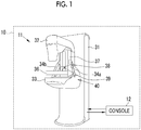
Fig. 1 is an explanation diagram illustrating the configuration of a mammography apparatus. -
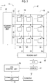
Fig. 2 is a block diagram illustrating the configuration of a radiography unit. -
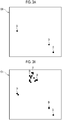
Fig. 3A is an explanation diagram illustrating defective pixel map data in a non-failure state andFig. 3B is an explanation diagram illustrating defective pixel map data in failure state. -
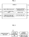
Fig. 4 is a block diagram illustrating the configuration of a console. -
Fig. 5 is a diagram illustrating a failure condition estimation unit. -
Fig. 6 is a flowchart illustrating the operation of the mammography apparatus. -
Fig. 7 is a block diagram illustrating a learning device that trains the failure condition estimation unit. - As illustrated in
Fig. 1 , amammography apparatus 10 which is an example of a radiography apparatus comprises an apparatusmain body 11 that captures an image of the breast of a subject using X-rays which are radiation and aconsole 12 that controls the apparatusmain body 11. The apparatusmain body 11 and theconsole 12 are connected wirelessly or in a wired manner and transmit and receive data and control signals therebetween if necessary. - The apparatus
main body 11 comprises, for example, asupport 31, anX-ray generation unit 32, an imaging table 33, acompression plate 36, and anelevating unit 37. TheX-ray generation unit 32 and the imaging table 33 are integrated to form amovable unit 40 whose position is adjusted according to the subject in the apparatusmain body 11. - The
X-ray generation unit 32 includes at least an X-ray tube that generates X-rays. Therefore, in themammography apparatus 10, theX-ray generation unit 32 is a radiation generation unit that generates radiation (X-rays). In addition, theX-ray generation unit 32 may include a high voltage circuit that supplies a high voltage for generating X-rays to an X-ray tube. That is, the X-raygeneration unit 32 may be configured by a so-called mono-tank. - The imaging table 33 is a stage on which the breast is placed and the breast is interposed between the imaging table 33 and the
compression plate 36 during imaging. In addition, the imaging table 33 forms a radiography unit that captures the image of the breast of the subject using radiation (X-rays). For example, the imaging table 33 includes, as the radiography unit, an FPD 41 (seeFig. 3 ) that captures the image of the breast using radiation and a grid that removes scattered radiation (a stationary Lysholm Blende or a mobile Bucky Blende). Further, themammography apparatus 10 may have a plurality of kinds of grids that can be replaced according to imaging conditions and may perform imaging using the grids. Agripping portion 34a that is gripped by the right hand of the subject and a grippingportion 34b that is gripped by the left hand of the subject are attached to the imaging table 33. The grippingportion 34a and thegripping portion 34b are so-called armrests. Since X-rays are used in this embodiment, the radiography unit is specifically an X-ray imaging unit. - The
compression plate 36 compresses and flattens the breast of the subject placed on the imaging table 33 during imaging. This is to reduce the overlap of the normal mammary glands and to easily find the candidates of a lesion such as calcification. The elevatingunit 37 moves up and down thecompression plate 36 with respect to the imaging table 33. Thus, the elevatingunit 37 supports thecompression plate 36 substantially in parallel to the imaging table 33 at a specific distance corresponding to the thickness of the breast. - The
movable unit 40 is rotatable in a predetermined angle range while maintaining the relative position and direction of theX-ray generation unit 32 and the imaging table 33. Therefore, the apparatusmain body 11 can perform imaging in a state in which the imaging table 33 is horizontally disposed or the imaging table 33 is disposed obliquely with respect to the horizontal direction. Specifically, the apparatusmain body 11 can perform craniocaudal imaging (CC imaging) in which the imaging table 33 is horizontally disposed and the image of the breast is captured in a craniocaudal direction. Further, the apparatusmain body 11 can perform mediolateral oblique imaging (MLO imaging) in which the imaging table 33 is obliquely disposed and the image of the breast is captured in a mediolateral oblique direction. - In the
movable unit 40, theX-ray generation unit 32 is rotatable in a predetermined range while the position of the imaging table 33 and thecompression plate 36 is fixed. Therefore, the apparatusmain body 11 can perform so-called stereo imaging and tomosynthesis imaging. The stereo imaging is an imaging aspect that captures the image of the breast of the subject, which is fixed at a specific position and in a specific direction (for example, the position and direction in the CC imaging), from one direction or a plurality of oblique directions with different inclination angles to obtain a perspective image (hereinafter, referred to as a stereo image) from the oblique direction. In addition, the tomosynthesis imaging is an imaging aspect that captures the images of the breast of the subject, which is fixed at a specific position and in a specific direction, from a plurality of oblique directions and obtains a tomographic image (hereinafter, referred to as a tomosynthesis image) of the breast of the subject using the captured images. - As illustrated in
Fig. 2 , theFPD 41 as the X-ray imaging unit comprises aconversion panel 42, ascanning driving unit 43, areading unit 44, anFPD control unit 45, an analog/digital (A/D)converter 46, amemory 47, and acommunication unit 48. Theconversion panel 42 has animaging region 50 in which a plurality ofpixels 49 that accumulate signal charge corresponding to the amount of incident X-rays are two-dimensionally arranged. For example, the plurality ofpixels 49 are arranged at a predetermined pitch in a matrix of G1 to Gn rows (X direction) and D1 to Dm columns (Y direction). The two-dimensional array of the pixels may be a square array as in this embodiment or may be a honeycomb array. - The
conversion panel 42 is, for example, a direct conversion type that directly converts X-rays into charge and accumulates signal charge (a first example of an electric signal). In theconversion panel 42, for example, amorphous selenium is used as an X-ray conversion film. In theconversion panel 42, a thin film transistor (TFT) 51, a capacitor (not illustrated) for accumulating signal charge, and apixel electrode 52 for defining apixel 49 are formed on an insulating substrate such as a glass substrate. Then, the X-ray conversion film is formed on theTFT 51 and thepixel electrode 52 in the entire surface of theimaging region 50 and a common electrode is formed on the X-ray conversion film. In a case in which X-rays are incident on theimaging region 50, the X-rays are converted into charge by the X-ray conversion film and signal charge is accumulated in eachpixel 49 through thepixel electrode 52. - The signal charge accumulated in the
pixel 49 is read by theTFT 51. TheTFT 51 has a gate electrode connected to ascanning line 53, a source electrode connected to asignal line 54, and a drain electrode connected to the capacitor of thepixel 49. The scanning lines 53 and thesignal lines 54 are arranged in a lattice shape. The number ofscanning lines 53 provided is equal to the number of rows (n rows) of thepixels 49 and the number ofsignal lines 54 provided is equal to the number of columns (m columns) of thepixels 49 in theimaging region 50. Thescanning line 53 is connected to thescanning driving unit 43 and thesignal line 54 is connected to thereading unit 44. - The
reading unit 44 includes an integration amplifier that converts the signal charge read from theconversion panel 42 into a voltage signal and a multiplexer that sequentially switches the columns of thepixels 49 in theimaging region 50 and sequentially outputs the voltage signals corresponding to each column. - The
reading unit 44 outputs the read voltage signal as an image signal to the A/D converter 46. The A/D converter 46 converts the image signal into digital data and writes the digital data into thememory 47 so as to be associated with coordinates indicating the position of thepixel 49 in theimaging region 50. TheFPD control unit 45 transmits the digital image signal in thememory 47 as an X-ray image to theconsole 12 through the wireless orwired communication unit 48. - The
mammography apparatus 10 performs defect correction calibration in addition to the capture of a general X-ray image. The defect correction calibration is calibration accompanied by X-ray irradiation. The defect correction calibration is a calibration for acquiringdefect correction data 61A and defective pixel map data which will be described below and is performed during periodic maintenance, in addition to during product shipment and installation. This is because the number of defective pixels change over time. - For example, the periodic maintenance is performed once a day on the day when X-ray imaging is performed using the
mammography apparatus 10. In the defect correction calibration, during the periodic maintenance, imaging is performed in a state in which themovable unit 40 is set to the direction and position corresponding to all types of imaging performed by themammography apparatus 10, such as CC imaging and MLO imaging, to acquire a calibration image. - The calibration image is an image acquired during defect correction calibration involving X-ray irradiation. In a case in which the
imaging region 50 is irradiated with X-rays in a state in which the subject does not exist in an irradiation path, the calibration image is generated by theFPD control unit 45 on the basis of the image signal output from theconversion panel 42. Since there is no subject, the entire surface of theimaging region 50 of theconversion panel 42 is uniformly irradiated with X-rays. Therefore, the sensitivity characteristics of eachpixel 49 or the information of a defective pixel is reflected in the calibration image. Similarly to the general X-ray image, theFPD control unit 45 transmits an image signal of the calibration image written into thememory 47 to theconsole 12 through thecommunication unit 48. - Since the calibration image is an image obtained by emitting X-rays, a defect caused by the defective pixel occurs in the calibration image. In an example of a calibration image C0 in a non-failure state illustrated in
Fig. 3A and an example of a calibration image C1 in a failure state illustrated inFig. 3B , alphabet D indicates a defective pixel. The defective pixel D is a pixel that is not sensitive to incident X-rays and does not generate charge, a pixel that generates change whose amount does not reach a reference range, or a pixel that generates change whose amount is more than the reference range. In the calibration image, a defect appears as a black spot or a white spot. InFigs. 3A and 3B , the defective pixel D is represented by a black spot. In the calibration image C1 in the failure state illustrated inFig. 3B , a plurality of defective pixels D occur in adjacent regions and the density of the defective pixels in the entire imaging region is higher than that in the non-failure state. The size of the defect varies depending on the number of defective pixels. - The
console 12 is a control device that controls themammography apparatus 10 and an information processing apparatus that processes information using various mammography images. As illustrated inFig. 4 , theconsole 12 comprises animage processing unit 61, a defective pixel mapdata acquisition unit 62, a failurecondition estimation unit 63, anotification unit 64, and adisplay unit 65. - The
image processing unit 61 performs various kinds of correction for the X-ray image on the basis of, for example, preset correction data. In this embodiment, theimage processing unit 61 performs defect correction on the basis of thedefect correction data 61A. Thedisplay unit 65 displays the X-ray image processed by theimage processing unit 61. - The
image processing unit 61 creates thedefect correction data 61A on the basis of the calibration image acquired during the defect correction calibration of theconversion panel 42. Thedefect correction data 61A is data for correcting abnormal data which is generated in the X-ray image due to the defective pixel among thepixels 49 of theconversion panel 42. The X-ray image in which abnormal data has been corrected is obtained by defect correction using thedefect correction data 61A. Specifically, the defect correction is performed by interpolation based on the data of normal pixels around the defective pixel. - In this embodiment, the calibration image is used to create the
defect correction data 61A in theimage processing unit 61 and is used as the defective pixel map data in the failurecondition estimation unit 63. - During the periodic maintenance, the defective pixel map
data acquisition unit 62 controls theX-ray generation unit 32 and the imaging table 33 (FPD 41) to acquire the calibration image (defective pixel map data). - The failure
condition estimation unit 63 receives the defective pixel map data acquired by the defective pixel mapdata acquisition unit 62 and estimates the failure probability of theFPD 41 and the usage state of theFPD 41 at the time of failure. - For example, as illustrated in
Fig. 5 , the failurecondition estimation unit 63 may be configured by a learned model (a so-called artificial intelligence (AI) program) that receives the defective pixel map data and outputs the failure probability or the usage state at the time of failure which is estimated in a case in which the subsequent imaging is performed using theFPD 41. - The failure probability is the probability that the
FPD 41 will be out of order within a preset time. The usage state at the time of failure is the time until theFPD 41 is out of order, the number of images captured until theFPD 41 is out of order, or the number of times a high voltage is applied to theFPD 41 until theFPD 41 is out of order. In addition, the radiography unit that detects radiation using an X-ray conversion film, such as an FPD, needs to apply a high voltage of several kilovolts (kV) (2 kV in the case of the FPD) in order to form an electric field for moving electrons and holes generated by the incidence of radiation in a case in which the apparatus starts up and during periodic maintenance. Here, in the radiography unit, the state of the defect changes with the lapse of time since the application of the high voltage. That is, as the number of times the high voltage is applied becomes larger, the probability of failure becomes higher and the state of the apparatus becomes closer to a failure state. - For example, the failure
condition estimation unit 63 uses learning data, in which the defective pixel map data actually acquired from theFPD 41 in the failure state is associated with the actual failure probability (100%), the time until theFPD 41 is out of order (0 hours), the number of images (0 images) captured until theFPD 41 is out of order, or the number of times the high voltage is applied to theFPD 41 until theFPD 41 is out of order, for machine learning. - In addition, as the learning data, learning data may be used in which the defective pixel map data acquired from the
FPD 41 in the non-failure state (X-ray imaging is not used) is associated with the failure probability, the time until theFPD 41 is out of order, the number of images captured until theFPD 41 is out of order, or the number of times the high voltage is applied to theFPD 41 until theFPD 41 is out of order. In this case, the product design value of theFPD 41 may be used as the value of the failure probability, the time until theFPD 41 is out of order, the number of images captured until theFPD 41 is out of order, or the number of times the high voltage is applied to theFPD 41 until theFPD 41 is out of order. - The failure
condition estimation unit 63 acquires evaluation values related to the defect from the defective pixel map data. Specifically, the failurecondition estimation unit 63 acquires feature amounts, such as the position of the defective pixels, the density of the defective pixels, the number of defective pixels, and a defect size, as the evaluation values from the defective pixel map data. In this case, the learned model is a learned model that has learned the relationship between the evaluation value and the failure probability or the usage state at the time of failure. - The
notification unit 64 sets a threshold value corresponding to the failure probability or the usage state at the time of failure estimated by the failurecondition estimation unit 63. In a case in which the value estimated by the failurecondition estimation unit 63 or the actual usage state for the estimation value is greater than the threshold value, thenotification unit 64 performs notification. As the threshold value set by thenotification unit 64, for example, the failure probability estimated by the failurecondition estimation unit 63 is equal to or greater than 80%, the actual number of imaging operations with respect to the number of imaging operations until the failure estimated by the failurecondition estimation unit 63 is equal to or greater than 80%, or the actual number of times the high voltage is applied with respect to the number of times the high voltage is applied until the failure estimated by the failurecondition estimation unit 63 is equal to or greater than 80%. In addition, for example, the user can set the threshold value used in thenotification unit 64 to any value using the input unit of theconsole 12. - For example, the
notification unit 64 generates a notification sound as the notification performed in a case in which the above-mentioned value is greater than the threshold value. Alternatively, thenotification unit 64 displays information related to the failure of theFPD 41 as the notification. For example, thenotification unit 64 displays information indicating that the failure probability is high or the failure time is near on thedisplay unit 65. - Next, the operation of the
mammography apparatus 10 having the above-mentioned configuration will be described. As illustrated inFig. 6 , for example, during the periodic maintenance, in a case in which defect correction calibration (Step S101), theFPD 41 outputs a calibration image. Then, the defective pixel mapdata acquisition unit 62 acquires defective pixel map data (Step S102). - In a case in which the defect correction calibration ends and the result of the periodic maintenance is displayed or the content of an imaging request received by the
console 12 is displayed, the failurecondition estimation unit 63 automatically estimates the failure probability or the usage state at the time of failure using the defective pixel map data (Step S103) and thedisplay unit 65 displays the failure probability or the usage state at the time of failure (Step S104). In a case in which the value acquired by the failurecondition estimation unit 63 or the actual usage state with respect to the estimation value is greater than the threshold value, notification is performed. - As described above, in a case in which the defective pixel map data has been acquired, the
console 12 estimates and displays the failure probability or the usage state at the time of failure. Since the estimation is performed using the learning model obtained by performing learning on the basis of the defective pixel map data and the usage state of theFPD 41, it is possible to predict the failure of theFPD 41 with high accuracy. In particular, in a case in which the evaluation values, such as the position of the defective pixels, the density of the defective pixels, the number of defective pixels, and a defect size, are acquired from the defective pixel map data and the relationship between the evaluation values and the failure probability or the usage state at the time of failure is learned, it is possible to predict the failure of theFPD 41 with higher accuracy. - In the above-described embodiment, during the periodic maintenance, the defect correction calibration is performed to acquire the defective pixel map data in response to a command from the
console 12 and the failure probability or the usage state at the time of failure is estimated. However, the invention is not limited thereto. During remote maintenance, the failurecondition estimation unit 63 may estimate the failure probability or the usage state at the time of failure. In this case, the defect correction calibration may be automatically performed at a preset time to acquire the defective pixel map data and the estimation result of the failure probability or the usage state at the time of the failure may be transmitted to, for example, an information processing apparatus that is installed in a remote place and is connected to theconsole 12 wirelessly or in a wired manner. - In the above-described embodiment, the failure
condition estimation unit 63 is an AI program. However, the failurecondition estimation unit 63 may not be the AI program, but may be configured to include the AI program. For example, the failurecondition estimation unit 63 can estimate the failure probability or the usage state at the time of failure, using the learned model that outputs the failure probability or the usage state at the time of failure in response to the input of the defective pixel map data. Therefore, in themammography apparatus 10, for example, the failurecondition estimation unit 63 can communicate with an information processing apparatus or an analysis apparatus provided with the learned model that operates in an apparatus other than theconsole 12 and can estimate the failure probability or the usage state at the time of failure using the learned model. In addition, since an AI program is included, a case in which the failurecondition estimation unit 63 is an AI program is an aspect of the case in which the failurecondition estimation unit 63 includes an AI program. In a case in which the failurecondition estimation unit 63 is an AI program and in a case in which the failurecondition estimation unit 63 includes an AI program, the accuracy of determination is particularly high. - The failure
condition estimation unit 63 which is an AI program can be trained using alearning device 101 illustrated inFig. 7 . Thelearning device 101 is a device for training (optimizing) the failurecondition estimation unit 63 and comprises a learningdata acquisition unit 111 and an evaluationfunction update unit 112. - The learning
data acquisition unit 111 acquires data used to train the failure condition estimation unit 63 (learning unit). Specifically, the learningdata acquisition unit 111 acquires learning data in which the defective pixel map data is associated with a recording value of the failure probability of theFPD 41 or the usage state at the time of failure as described in the above-mentioned embodiment. Then, the learningdata acquisition unit 111 inputs the defective pixel map data as an explanatory variable and the recording value of the failure probability of theFPD 41 or the usage state at the time of failure as a correct answer label to the failurecondition estimation unit 63 to be trained. - The failure
condition estimation unit 63 calculates an estimation value (so-called evaluation value) of an objective variable, using the defective pixel map data as the explanatory variable and an evaluation model (for example, an evaluation function used in a specific regression analysis model) that obtains the objective variable from the explanatory variable, and outputs an error between the estimation value of the objective variable and the correct answer label. In this learning, the objective variable is the range of the failure probability of theFPD 41 or the usage state at the time of failure. - The evaluation
function update unit 112 optimizes the values of parameters used by the failurecondition estimation unit 63 in the evaluation model, using the error between the estimation value of the objective variable and the correct answer label output from the failurecondition estimation unit 63 that is performing learning. The optimization means an operation that calculates parameters for minimizing the error for a plurality of sets of the explanatory variables and the correct answer labels and updates the parameters used in the evaluation model to the calculated parameters. The failurecondition estimation unit 63 becomes an optimized evaluation model (learned model) by the repetition of the above-mentioned learning by thelearning device 101. - The
learning device 101 is a device that performs so-called supervised learning. However, thelearning device 101 can train the failurecondition estimation unit 63 using unsupervised learning or reinforcement learning. In addition, the evaluation model and the optimization method may be changed according to a specific learning aspect. Further, the failurecondition estimation unit 63 may be optimized by supervised learning using an explanatory variable, an objective variable, and/or an evaluation model different from those in thelearning device 101. - The reinforcement learning is a method which sets a state, an action, and an evaluation value according to the environment and calculates the action of optimizing the cumulative sum of the evaluation values in all of the set states and is applied to a technique such as obstacle avoidance. In a case in which the reinforcement learning is applied to the
learning device 101, first, feature amounts are extracted on the basis of the learning data acquired by the learningdata acquisition unit 111. The feature amounts may be feature amounts that can be extracted from learning data other than the position of the defective pixels, the density of the defective pixels, the defect size described in the above-mentioned embodiment. For example, an imaging interval and the frequency of imaging until the defective pixel map data is acquired may be extracted as the feature amounts. The failurecondition estimation unit 63 as a learning unit calculates a new evaluation model on the basis of the extracted feature amounts and updates the evaluation model to the new evaluation model. - In the learning data used for learning in the embodiment and the modification examples, the above-mentioned defective pixel map data, the recording value of the failure probability of the
FPD 41 or the usage state at the time of failure, and any one of the number of images captured until theFPD 41 is out of order after the acquisition of the defective pixel map data, the time until theFPD 41 is out of order after the acquisition of the defective pixel map data, or the imaging frequency of theFPD 41 per predetermined time may be associated with each other. - For example, in the embodiment and the modification examples, the
console 12 functions as the information processing apparatus. However, another information processing apparatus (for example, a computer functioning as the analysis apparatus) which is operatively associated with theconsole 12 may have the functions of theconsole 12 as the information processing apparatus. For example, in each of the embodiment and the modification examples, the apparatusmain body 11 may have the functions of theconsole 12 as the information processing apparatus. For example, in each of the embodiments and the modification examples, in a case in which theconsole 12 or the apparatusmain body 11 has the functions of theconsole 12 as the information processing apparatus, theentire mammography apparatus 10 functions as the information processing apparatus. In addition, for example, in each of the embodiments and the modification examples, the functions of theconsole 12 as the information processing apparatus may be dispersed to a plurality of apparatuses (for example, a plurality of computers). - For example, in the above-described embodiments, the following various processors can be used as the hardware structure of processing units performing various processes, such as the
image processing unit 61, the defective pixel mapdata acquisition unit 62, the failurecondition estimation unit 63, the learningdata acquisition unit 111, and the evaluationfunction update unit 112. The various processors include a CPU which is a general-purpose processor executing software (program) to function as various processing units, a graphical processing unit (GPU), a programmable logic device (PLD), such as a field programmable gate array (FPGA), which is a processor whose circuit configuration can be changed after manufacture, and a dedicated electric circuit which is a processor having a dedicated circuit configuration designed to perform various processes. - One processing unit may be configured by one of the various processors or a combination of two or more processors of the same type or different types (for example, a combination of a plurality of FPGAs and a combination of a CPU and an FPGA). In addition, a plurality of processing units may be configured by one processor. A first example of the configuration in which a plurality of processing units are configured by one processor is an aspect in which one processor is configured by a combination of one or more CPUs and software and functions as a plurality of processing units. A representative example of this aspect is a client computer or a server computer. A second example of the configuration is an aspect in which a processor that implements the functions of the entire system including a plurality of processing units using one integrated circuit (IC) chip is used. A representative example of this aspect is a system-on-chip (SoC). As such, various processing units are configured by using one or more of the various processors as a hardware structure.
- In addition, specifically, an electric circuit (circuitry) obtained by combining circuit elements, such as semiconductor elements, can be used as the hardware structure of the various processors.
-
- 10: mammography apparatus
- 11: apparatus main body
- 12: console
- 31: support
- 32: X-ray generation unit
- 33: imaging table
- 34a: gripping portion
- 34b: gripping portion
- 36: compression plate
- 37: elevating unit
- 40: movable unit
- 41: FPD
- 42: conversion panel
- 43: scanning driving unit
- 44: reading unit
- 45: FPD control unit
- 46: analog/digital (A/D) converter
- 47: memory
- 48: communication unit
- 49: pixel
- 50: imaging region
- 51: thin film transistor (TFT)
- 52: pixel electrode
- 53: scanning line
- 54: signal line
- 61: image processing unit
- 61A: defect correction data
- 62: defective pixel map data acquisition unit
- 63: failure condition estimation unit
- 64: notification unit
- 65: display unit
- 101: learning device
- 111: learning data acquisition unit
- 112: evaluation function update unit
- C0: calibration image
- C1: calibration image
- D: defective pixel
Claims (10)
- An information processing apparatus comprising:a defective pixel map data acquisition unit that acquires defective pixel map data indicating positional information of a defective pixel which is defective among a plurality of pixels forming a radiography unit; anda failure condition estimation unit that estimates a failure probability of the radiography unit or a usage state of the radiography unit at the time of failure, using a learned model that receives the defective pixel map data and outputs the failure probability of the radiography unit or the usage state of the radiography unit at the time of failure.
- The information processing apparatus according to claim 1, further comprising:
a notification unit that sets a threshold value corresponding to the failure probability or the usage state at the time of failure estimated by the failure condition estimation unit and performs notification in a case in which the failure probability or the usage state at the time of failure is greater than the threshold value. - The information processing apparatus according to claim 1 or 2,
wherein the defective pixel map data acquisition unit acquires a calibration image output from the radiography unit as the defective pixel map data. - The information processing apparatus according to any one of claims 1 to 3,
wherein the failure probability is a probability that the radiography unit will be out of order within a preset time. - The information processing apparatus according to any one of claims 1 to 4,
wherein the usage state at the time of failure is a time until the radiography unit is out of order, the number of images captured until the radiography unit is out of order, or the number of times a high voltage is applied to the radiography unit until the radiography unit is out of order. - A learning device comprising:a learning data acquisition unit that acquires learning data in which defective pixel map data indicating positional information of a defective pixel which is defective among a plurality of pixels forming a radiography unit is associated with a recording value of a failure probability of the radiography unit or a usage state of the radiography unit at the time of failure;a learning unit that calculates an evaluation value of the failure probability or the usage state at the time of failure from the defective pixel map data using an evaluation function; andan evaluation function update unit that updates the evaluation function, using an error between the evaluation value of the failure probability or the usage state at the time of failure calculated by the learning unit using the evaluation function and the recording value of the failure probability or the usage state at the time of failure in the learning data, in a case in which the learning data is acquired,wherein the learning unit uses the evaluation function updated by the evaluation function update unit.
- The learning device according to claim 6,
wherein the failure probability is a probability that the radiography unit will be out of order within a preset time. - The learning device according to claim 6 or 7,
wherein the usage state at the time of failure is the number of images captured until the radiography unit is out of order after the use of the radiography unit starts or the number of times a high voltage is applied to the radiography unit until the radiography unit is out of order. - The learning device according to any one of claims 6 to 8,
wherein, in the learning data, any one of the number of images captured until the radiography unit is out of order after the defective pixel map data is acquired, a time until the radiography unit is out of order after the defective pixel map data is acquired, or an imaging frequency of the radiography unit per predetermined time, the defective pixel map data, and the recording value of the failure probability of the radiography unit or the usage state of the radiography unit at the time of failure are associated with each other. - A program that drives an information processing apparatus comprising a defective pixel map data acquisition unit that acquires defective pixel map data indicating positional information of a defective pixel which is defective among a plurality of pixels forming a radiography unit, the program causing the information processing apparatus to perform:
estimating a failure probability of the radiography unit or a usage state of the radiography unit at the time of failure, using a learned model that receives the defective pixel map data and outputs the failure probability of the radiography unit or the usage state of the radiography unit at the time of failure.
Applications Claiming Priority (1)
| Application Number | Priority Date | Filing Date | Title |
|---|---|---|---|
| JP2019047651A JP2020146291A (en) | 2019-03-14 | 2019-03-14 | Information processing apparatus, learning apparatus, and program |
Publications (2)
| Publication Number | Publication Date |
|---|---|
| EP3708086A1 true EP3708086A1 (en) | 2020-09-16 |
| EP3708086B1 EP3708086B1 (en) | 2021-02-24 |
Family
ID=69844385
Family Applications (1)
| Application Number | Title | Priority Date | Filing Date |
|---|---|---|---|
| EP20162444.2A Active EP3708086B1 (en) | 2019-03-14 | 2020-03-11 | Information processing apparatus, learning device, and program |
Country Status (3)
| Country | Link |
|---|---|
| US (1) | US11337672B2 (en) |
| EP (1) | EP3708086B1 (en) |
| JP (1) | JP2020146291A (en) |
Families Citing this family (2)
| Publication number | Priority date | Publication date | Assignee | Title |
|---|---|---|---|---|
| JP6914413B1 (en) * | 2020-12-07 | 2021-08-04 | 前田道路株式会社 | Asphalt mixture density estimation method and density estimation system |
| JP2024017481A (en) * | 2022-07-28 | 2024-02-08 | キヤノンメディカルシステムズ株式会社 | X-ray CT device, data collection system, data collection method, and program |
Citations (3)
| Publication number | Priority date | Publication date | Assignee | Title |
|---|---|---|---|---|
| US20110073769A1 (en) * | 2009-09-29 | 2011-03-31 | Fujifilm Corporation | Radiographic image capture managing system, and radiographic image capture managing method |
| US20170188443A1 (en) * | 2014-05-29 | 2017-06-29 | Hitachi, Ltd. | X-Ray Tube Predictive Fault Indicator Sensing Device, X-Ray Tube Predictive Fault Indicator Sensing Method, and X-Ray Imaging Device |
| US20180253624A1 (en) * | 2017-03-06 | 2018-09-06 | Siemens Medical Solutions Usa, Inc. | Defective Pixel Identification Using Machine Learning |
Family Cites Families (2)
| Publication number | Priority date | Publication date | Assignee | Title |
|---|---|---|---|---|
| JP3234742B2 (en) * | 1995-05-25 | 2001-12-04 | 株式会社東芝 | Method and apparatus for estimating remaining life of electronic component |
| JPH11183628A (en) * | 1997-12-24 | 1999-07-09 | Ge Yokogawa Medical Systems Ltd | Method and device for inspecting radiation detector and radiation tomograph |
-
2019
- 2019-03-14 JP JP2019047651A patent/JP2020146291A/en not_active Abandoned
-
2020
- 2020-03-11 EP EP20162444.2A patent/EP3708086B1/en active Active
- 2020-03-12 US US16/817,569 patent/US11337672B2/en active Active
Patent Citations (4)
| Publication number | Priority date | Publication date | Assignee | Title |
|---|---|---|---|---|
| US20110073769A1 (en) * | 2009-09-29 | 2011-03-31 | Fujifilm Corporation | Radiographic image capture managing system, and radiographic image capture managing method |
| JP2011072417A (en) | 2009-09-29 | 2011-04-14 | Fujifilm Corp | Radiography management system and radiography management method |
| US20170188443A1 (en) * | 2014-05-29 | 2017-06-29 | Hitachi, Ltd. | X-Ray Tube Predictive Fault Indicator Sensing Device, X-Ray Tube Predictive Fault Indicator Sensing Method, and X-Ray Imaging Device |
| US20180253624A1 (en) * | 2017-03-06 | 2018-09-06 | Siemens Medical Solutions Usa, Inc. | Defective Pixel Identification Using Machine Learning |
Also Published As
| Publication number | Publication date |
|---|---|
| US11337672B2 (en) | 2022-05-24 |
| US20200289081A1 (en) | 2020-09-17 |
| JP2020146291A (en) | 2020-09-17 |
| EP3708086B1 (en) | 2021-02-24 |
Similar Documents
| Publication | Publication Date | Title |
|---|---|---|
| US11850084B2 (en) | Fracture risk evaluation value acquisition device, method for operating fracture risk evaluation value acquisition device, and non-transitory computer readable medium | |
| JP5405093B2 (en) | Image processing apparatus and image processing method | |
| US8905636B2 (en) | X-ray diagnostic apparatus | |
| US7203279B2 (en) | Radiographic apparatus, and radiation detection signal processing method | |
| JP2004329932A (en) | Method and apparatus for processing fluoroscopic image | |
| US12127850B2 (en) | Motor organ disease prediction device, motor organ disease prediction method, motor organ disease prediction program, learning device, learning method, learning program, and learned neural network | |
| EP3708086B1 (en) | Information processing apparatus, learning device, and program | |
| US10898145B2 (en) | Image display device, image display method, and image display program | |
| US9572543B2 (en) | Tomography system | |
| US20200100754A1 (en) | Radiography control apparatus, radiographic imaging apparatus, and radiographic imaging system | |
| JP2003023572A (en) | Method and apparatus for pixel replacement in panel detector | |
| CN116172591A (en) | Dynamic quality management device, program and method thereof | |
| US20160349195A1 (en) | Image processing devices, image processing system, image processing method, and non-transitory recording medium | |
| US20220284573A1 (en) | Radiographic failure determination support device and recording medium | |
| US20210353241A1 (en) | Subject information acquisition device, method for operating subject information acquisition device, and non-transitory computer readable medium | |
| WO2024169466A1 (en) | Method for x-ray imaging system, electronic device and x-ray imaging system | |
| US12417523B2 (en) | Dynamic imaging quality control device, storage medium for dynamic imaging quality control program, and dynamic imaging quality control method | |
| JP2021186199A (en) | Radiation imaging system, its control method, and program | |
| JP7826614B2 (en) | Dynamic quality control device, dynamic quality control program, and dynamic quality control method | |
| US20230263494A1 (en) | Re-imaging determination support device, learning device, re-imaging support device, recording medium, and re-imaging determination support method | |
| US20240361471A1 (en) | Radiation imaging apparatus and radiation imaging system | |
| US20250184444A1 (en) | Dynamic image display device, dynamic image display method and recording medium | |
| JP7115584B2 (en) | Dynamic quality control device, dynamic quality control program and dynamic quality control method | |
| JP2021023611A (en) | X-ray diagnostic device and medical image processing device | |
| JP7767358B2 (en) | Image processing device, radiation imaging system, operation method of image processing device, and program |
Legal Events
| Date | Code | Title | Description |
|---|---|---|---|
| PUAI | Public reference made under article 153(3) epc to a published international application that has entered the european phase |
Free format text: ORIGINAL CODE: 0009012 |
|
| STAA | Information on the status of an ep patent application or granted ep patent |
Free format text: STATUS: THE APPLICATION HAS BEEN PUBLISHED |
|
| STAA | Information on the status of an ep patent application or granted ep patent |
Free format text: STATUS: REQUEST FOR EXAMINATION WAS MADE |
|
| AK | Designated contracting states |
Kind code of ref document: A1 Designated state(s): AL AT BE BG CH CY CZ DE DK EE ES FI FR GB GR HR HU IE IS IT LI LT LU LV MC MK MT NL NO PL PT RO RS SE SI SK SM TR |
|
| AX | Request for extension of the european patent |
Extension state: BA ME |
|
| 17P | Request for examination filed |
Effective date: 20200831 |
|
| RBV | Designated contracting states (corrected) |
Designated state(s): AL AT BE BG CH CY CZ DE DK EE ES FI FR GB GR HR HU IE IS IT LI LT LU LV MC MK MT NL NO PL PT RO RS SE SI SK SM TR |
|
| GRAP | Despatch of communication of intention to grant a patent |
Free format text: ORIGINAL CODE: EPIDOSNIGR1 |
|
| STAA | Information on the status of an ep patent application or granted ep patent |
Free format text: STATUS: GRANT OF PATENT IS INTENDED |
|
| RIC1 | Information provided on ipc code assigned before grant |
Ipc: G16H 30/20 20180101ALI20201002BHEP Ipc: G16H 40/40 20180101ALI20201002BHEP Ipc: G16H 40/63 20180101ALI20201002BHEP Ipc: A61B 6/00 20060101AFI20201002BHEP |
|
| INTG | Intention to grant announced |
Effective date: 20201021 |
|
| GRAS | Grant fee paid |
Free format text: ORIGINAL CODE: EPIDOSNIGR3 |
|
| GRAA | (expected) grant |
Free format text: ORIGINAL CODE: 0009210 |
|
| STAA | Information on the status of an ep patent application or granted ep patent |
Free format text: STATUS: THE PATENT HAS BEEN GRANTED |
|
| AK | Designated contracting states |
Kind code of ref document: B1 Designated state(s): AL AT BE BG CH CY CZ DE DK EE ES FI FR GB GR HR HU IE IS IT LI LT LU LV MC MK MT NL NO PL PT RO RS SE SI SK SM TR |
|
| RAP1 | Party data changed (applicant data changed or rights of an application transferred) |
Owner name: FUJIFILM CORPORATION |
|
| REG | Reference to a national code |
Ref country code: CH Ref legal event code: EP |
|
| REG | Reference to a national code |
Ref country code: AT Ref legal event code: REF Ref document number: 1363482 Country of ref document: AT Kind code of ref document: T Effective date: 20210315 |
|
| REG | Reference to a national code |
Ref country code: IE Ref legal event code: FG4D |
|
| REG | Reference to a national code |
Ref country code: DE Ref legal event code: R096 Ref document number: 602020000012 Country of ref document: DE |
|
| RAP4 | Party data changed (patent owner data changed or rights of a patent transferred) |
Owner name: FUJIFILM CORPORATION |
|
| REG | Reference to a national code |
Ref country code: LT Ref legal event code: MG9D |
|
| REG | Reference to a national code |
Ref country code: NL Ref legal event code: MP Effective date: 20210224 |
|
| PG25 | Lapsed in a contracting state [announced via postgrant information from national office to epo] |
Ref country code: LT Free format text: LAPSE BECAUSE OF FAILURE TO SUBMIT A TRANSLATION OF THE DESCRIPTION OR TO PAY THE FEE WITHIN THE PRESCRIBED TIME-LIMIT Effective date: 20210224 Ref country code: NO Free format text: LAPSE BECAUSE OF FAILURE TO SUBMIT A TRANSLATION OF THE DESCRIPTION OR TO PAY THE FEE WITHIN THE PRESCRIBED TIME-LIMIT Effective date: 20210524 Ref country code: PT Free format text: LAPSE BECAUSE OF FAILURE TO SUBMIT A TRANSLATION OF THE DESCRIPTION OR TO PAY THE FEE WITHIN THE PRESCRIBED TIME-LIMIT Effective date: 20210624 Ref country code: FI Free format text: LAPSE BECAUSE OF FAILURE TO SUBMIT A TRANSLATION OF THE DESCRIPTION OR TO PAY THE FEE WITHIN THE PRESCRIBED TIME-LIMIT Effective date: 20210224 Ref country code: GR Free format text: LAPSE BECAUSE OF FAILURE TO SUBMIT A TRANSLATION OF THE DESCRIPTION OR TO PAY THE FEE WITHIN THE PRESCRIBED TIME-LIMIT Effective date: 20210525 Ref country code: BG Free format text: LAPSE BECAUSE OF FAILURE TO SUBMIT A TRANSLATION OF THE DESCRIPTION OR TO PAY THE FEE WITHIN THE PRESCRIBED TIME-LIMIT Effective date: 20210524 Ref country code: HR Free format text: LAPSE BECAUSE OF FAILURE TO SUBMIT A TRANSLATION OF THE DESCRIPTION OR TO PAY THE FEE WITHIN THE PRESCRIBED TIME-LIMIT Effective date: 20210224 |
|
| REG | Reference to a national code |
Ref country code: AT Ref legal event code: MK05 Ref document number: 1363482 Country of ref document: AT Kind code of ref document: T Effective date: 20210224 |
|
| PG25 | Lapsed in a contracting state [announced via postgrant information from national office to epo] |
Ref country code: LV Free format text: LAPSE BECAUSE OF FAILURE TO SUBMIT A TRANSLATION OF THE DESCRIPTION OR TO PAY THE FEE WITHIN THE PRESCRIBED TIME-LIMIT Effective date: 20210224 Ref country code: NL Free format text: LAPSE BECAUSE OF FAILURE TO SUBMIT A TRANSLATION OF THE DESCRIPTION OR TO PAY THE FEE WITHIN THE PRESCRIBED TIME-LIMIT Effective date: 20210224 Ref country code: PL Free format text: LAPSE BECAUSE OF FAILURE TO SUBMIT A TRANSLATION OF THE DESCRIPTION OR TO PAY THE FEE WITHIN THE PRESCRIBED TIME-LIMIT Effective date: 20210224 Ref country code: RS Free format text: LAPSE BECAUSE OF FAILURE TO SUBMIT A TRANSLATION OF THE DESCRIPTION OR TO PAY THE FEE WITHIN THE PRESCRIBED TIME-LIMIT Effective date: 20210224 Ref country code: SE Free format text: LAPSE BECAUSE OF FAILURE TO SUBMIT A TRANSLATION OF THE DESCRIPTION OR TO PAY THE FEE WITHIN THE PRESCRIBED TIME-LIMIT Effective date: 20210224 |
|
| PG25 | Lapsed in a contracting state [announced via postgrant information from national office to epo] |
Ref country code: IS Free format text: LAPSE BECAUSE OF FAILURE TO SUBMIT A TRANSLATION OF THE DESCRIPTION OR TO PAY THE FEE WITHIN THE PRESCRIBED TIME-LIMIT Effective date: 20210624 |
|
| PG25 | Lapsed in a contracting state [announced via postgrant information from national office to epo] |
Ref country code: SM Free format text: LAPSE BECAUSE OF FAILURE TO SUBMIT A TRANSLATION OF THE DESCRIPTION OR TO PAY THE FEE WITHIN THE PRESCRIBED TIME-LIMIT Effective date: 20210224 Ref country code: AT Free format text: LAPSE BECAUSE OF FAILURE TO SUBMIT A TRANSLATION OF THE DESCRIPTION OR TO PAY THE FEE WITHIN THE PRESCRIBED TIME-LIMIT Effective date: 20210224 Ref country code: CZ Free format text: LAPSE BECAUSE OF FAILURE TO SUBMIT A TRANSLATION OF THE DESCRIPTION OR TO PAY THE FEE WITHIN THE PRESCRIBED TIME-LIMIT Effective date: 20210224 Ref country code: EE Free format text: LAPSE BECAUSE OF FAILURE TO SUBMIT A TRANSLATION OF THE DESCRIPTION OR TO PAY THE FEE WITHIN THE PRESCRIBED TIME-LIMIT Effective date: 20210224 |
|
| REG | Reference to a national code |
Ref country code: DE Ref legal event code: R097 Ref document number: 602020000012 Country of ref document: DE |
|
| PG25 | Lapsed in a contracting state [announced via postgrant information from national office to epo] |
Ref country code: MC Free format text: LAPSE BECAUSE OF FAILURE TO SUBMIT A TRANSLATION OF THE DESCRIPTION OR TO PAY THE FEE WITHIN THE PRESCRIBED TIME-LIMIT Effective date: 20210224 Ref country code: DK Free format text: LAPSE BECAUSE OF FAILURE TO SUBMIT A TRANSLATION OF THE DESCRIPTION OR TO PAY THE FEE WITHIN THE PRESCRIBED TIME-LIMIT Effective date: 20210224 Ref country code: SK Free format text: LAPSE BECAUSE OF FAILURE TO SUBMIT A TRANSLATION OF THE DESCRIPTION OR TO PAY THE FEE WITHIN THE PRESCRIBED TIME-LIMIT Effective date: 20210224 Ref country code: RO Free format text: LAPSE BECAUSE OF FAILURE TO SUBMIT A TRANSLATION OF THE DESCRIPTION OR TO PAY THE FEE WITHIN THE PRESCRIBED TIME-LIMIT Effective date: 20210224 |
|
| PLBE | No opposition filed within time limit |
Free format text: ORIGINAL CODE: 0009261 |
|
| STAA | Information on the status of an ep patent application or granted ep patent |
Free format text: STATUS: NO OPPOSITION FILED WITHIN TIME LIMIT |
|
| PG25 | Lapsed in a contracting state [announced via postgrant information from national office to epo] |
Ref country code: ES Free format text: LAPSE BECAUSE OF FAILURE TO SUBMIT A TRANSLATION OF THE DESCRIPTION OR TO PAY THE FEE WITHIN THE PRESCRIBED TIME-LIMIT Effective date: 20210224 Ref country code: AL Free format text: LAPSE BECAUSE OF FAILURE TO SUBMIT A TRANSLATION OF THE DESCRIPTION OR TO PAY THE FEE WITHIN THE PRESCRIBED TIME-LIMIT Effective date: 20210224 Ref country code: FR Free format text: LAPSE BECAUSE OF NON-PAYMENT OF DUE FEES Effective date: 20210424 |
|
| 26N | No opposition filed |
Effective date: 20211125 |
|
| PG25 | Lapsed in a contracting state [announced via postgrant information from national office to epo] |
Ref country code: IT Free format text: LAPSE BECAUSE OF FAILURE TO SUBMIT A TRANSLATION OF THE DESCRIPTION OR TO PAY THE FEE WITHIN THE PRESCRIBED TIME-LIMIT Effective date: 20210224 |
|
| PG25 | Lapsed in a contracting state [announced via postgrant information from national office to epo] |
Ref country code: IS Free format text: LAPSE BECAUSE OF FAILURE TO SUBMIT A TRANSLATION OF THE DESCRIPTION OR TO PAY THE FEE WITHIN THE PRESCRIBED TIME-LIMIT Effective date: 20210624 |
|
| REG | Reference to a national code |
Ref country code: BE Ref legal event code: MM Effective date: 20220331 |
|
| PG25 | Lapsed in a contracting state [announced via postgrant information from national office to epo] |
Ref country code: LU Free format text: LAPSE BECAUSE OF NON-PAYMENT OF DUE FEES Effective date: 20220311 Ref country code: IE Free format text: LAPSE BECAUSE OF NON-PAYMENT OF DUE FEES Effective date: 20220311 |
|
| PG25 | Lapsed in a contracting state [announced via postgrant information from national office to epo] |
Ref country code: BE Free format text: LAPSE BECAUSE OF NON-PAYMENT OF DUE FEES Effective date: 20220331 |
|
| P01 | Opt-out of the competence of the unified patent court (upc) registered |
Effective date: 20230515 |
|
| PG25 | Lapsed in a contracting state [announced via postgrant information from national office to epo] |
Ref country code: HU Free format text: LAPSE BECAUSE OF FAILURE TO SUBMIT A TRANSLATION OF THE DESCRIPTION OR TO PAY THE FEE WITHIN THE PRESCRIBED TIME-LIMIT; INVALID AB INITIO Effective date: 20200311 |
|
| REG | Reference to a national code |
Ref country code: CH Ref legal event code: PL |
|
| PG25 | Lapsed in a contracting state [announced via postgrant information from national office to epo] |
Ref country code: LI Free format text: LAPSE BECAUSE OF NON-PAYMENT OF DUE FEES Effective date: 20230331 Ref country code: CH Free format text: LAPSE BECAUSE OF NON-PAYMENT OF DUE FEES Effective date: 20230331 |
|
| PG25 | Lapsed in a contracting state [announced via postgrant information from national office to epo] |
Ref country code: MK Free format text: LAPSE BECAUSE OF FAILURE TO SUBMIT A TRANSLATION OF THE DESCRIPTION OR TO PAY THE FEE WITHIN THE PRESCRIBED TIME-LIMIT Effective date: 20210224 Ref country code: CY Free format text: LAPSE BECAUSE OF FAILURE TO SUBMIT A TRANSLATION OF THE DESCRIPTION OR TO PAY THE FEE WITHIN THE PRESCRIBED TIME-LIMIT Effective date: 20210224 |
|
| PG25 | Lapsed in a contracting state [announced via postgrant information from national office to epo] |
Ref country code: MT Free format text: LAPSE BECAUSE OF FAILURE TO SUBMIT A TRANSLATION OF THE DESCRIPTION OR TO PAY THE FEE WITHIN THE PRESCRIBED TIME-LIMIT Effective date: 20210224 |
|
| GBPC | Gb: european patent ceased through non-payment of renewal fee |
Effective date: 20240311 |
|
| PG25 | Lapsed in a contracting state [announced via postgrant information from national office to epo] |
Ref country code: GB Free format text: LAPSE BECAUSE OF NON-PAYMENT OF DUE FEES Effective date: 20240311 |
|
| PG25 | Lapsed in a contracting state [announced via postgrant information from national office to epo] |
Ref country code: GB Free format text: LAPSE BECAUSE OF NON-PAYMENT OF DUE FEES Effective date: 20240311 |
|
| PG25 | Lapsed in a contracting state [announced via postgrant information from national office to epo] |
Ref country code: TR Free format text: LAPSE BECAUSE OF FAILURE TO SUBMIT A TRANSLATION OF THE DESCRIPTION OR TO PAY THE FEE WITHIN THE PRESCRIBED TIME-LIMIT Effective date: 20210224 |
|
| PG25 | Lapsed in a contracting state [announced via postgrant information from national office to epo] |
Ref country code: SI Free format text: LAPSE BECAUSE OF FAILURE TO SUBMIT A TRANSLATION OF THE DESCRIPTION OR TO PAY THE FEE WITHIN THE PRESCRIBED TIME-LIMIT Effective date: 20210224 |
|
| PGFP | Annual fee paid to national office [announced via postgrant information from national office to epo] |
Ref country code: DE Payment date: 20260128 Year of fee payment: 7 |