EP3708035A1 - Accessoire pèle-ail manuel - Google Patents
Accessoire pèle-ail manuel Download PDFInfo
- Publication number
- EP3708035A1 EP3708035A1 EP20162869.0A EP20162869A EP3708035A1 EP 3708035 A1 EP3708035 A1 EP 3708035A1 EP 20162869 A EP20162869 A EP 20162869A EP 3708035 A1 EP3708035 A1 EP 3708035A1
- Authority
- EP
- European Patent Office
- Prior art keywords
- working chamber
- tubular body
- open end
- section
- restriction
- Prior art date
- Legal status (The legal status is an assumption and is not a legal conclusion. Google has not performed a legal analysis and makes no representation as to the accuracy of the status listed.)
- Granted
Links
Images
Classifications
-
- A—HUMAN NECESSITIES
- A47—FURNITURE; DOMESTIC ARTICLES OR APPLIANCES; COFFEE MILLS; SPICE MILLS; SUCTION CLEANERS IN GENERAL
- A47J—KITCHEN EQUIPMENT; COFFEE MILLS; SPICE MILLS; APPARATUS FOR MAKING BEVERAGES
- A47J17/00—Household peeling, stringing, or paring implements or machines
- A47J17/02—Hand devices for scraping or peeling vegetables or the like
-
- A—HUMAN NECESSITIES
- A47—FURNITURE; DOMESTIC ARTICLES OR APPLIANCES; COFFEE MILLS; SPICE MILLS; SUCTION CLEANERS IN GENERAL
- A47J—KITCHEN EQUIPMENT; COFFEE MILLS; SPICE MILLS; APPARATUS FOR MAKING BEVERAGES
- A47J17/00—Household peeling, stringing, or paring implements or machines
- A47J17/10—Vegetable or fruit grippers or holders for use while peeling
Definitions
- the present invention relates generally to the field of culinary preparation accessories.
- the present invention relates more particularly to a manual garlic peeler accessory provided to facilitate the removal of the outer shell of one or more garlic cloves.
- a manual garlic peeler comprising a tubular body having a hollow interior extending from a first open end to a second open end, in which the tubular body is made of flexible material allowing the tubular body to deform under the effect of pressure exerted during use of the garlic peeler accessory.
- the tubular body has a cylindrical geometry and the garlic cloves tend to escape through one or the other of the open ends when using the accessory.
- the document CN204683289U proposes to provide a manual garlic peeler in which the tubular body forms a working chamber extending between a first section restriction and a second section restriction, each arranged at a distance from the open ends. These arrangements help to improve the retention of the garlic cloves within the working chamber, however the distance between each of the section restrictions and the adjacent open end is small, so this improvement is limited.
- the interior surface of the tubular body has spikes, which makes the garlic peeler accessory difficult to clean.
- An object of the present invention is to provide a manual garlic peeler accessory of the above type which is efficient and easy to use.
- An object of the present invention is to provide a manual garlic peeler accessory of the aforementioned type which is easy to produce.
- a manual garlic peeler attachment comprising a tubular body having a first open end, a second open end opposite. at the first open end, and a hollow interior extending from the first open end to the second open end, the tubular body being made of a flexible material allowing the tubular body to deform under the effect of a pressure exerted during 'use of the garlic peeler attachment, the tubular body providing a first working chamber configured to house at least one clove of garlic, the tubular body having a first section restriction arranged at a distance from the first open end and a second section restriction, the first working chamber extending between the first section restriction and the second section restriction, because the tubular body has a second working chamber configured to accommodate at least the major part of a pod garlic, the second working chamber being arranged between the first section restriction and the first open end, the second working chamber being ant delimited by the first section restriction and by a third section restriction.
- the third section restriction coincides with the first open end. This arrangement makes it possible to simplify the production of the garlic peeler accessory.
- a first maximum section of the first working chamber is greater than a second maximum section of the second working chamber.
- the user can thus preferably accommodate the clove (s) of garlic to be peeled. in the first working chamber, and rolling the accessory, preferably directing the clove (s) of garlic towards the first restriction separating the first working chamber from the second working chamber.
- the second section restriction is arranged at a distance from the second open end, and the tubular body has a third working chamber configured to house at least the major part of a clove of garlic, the third working chamber being arranged between the second section restriction and the second open end, the third working chamber being delimited by the second section restriction and by a fourth section restriction.
- This arrangement allows better use of the first working chamber by facilitating the retention of the garlic cloves escaping from the first working chamber by the first section restriction or by the second section restriction.
- User palpating for the presence of garlic cloves in the second working chamber or in the third working chamber, or seeing garlic cloves start to come out from the first open end or the second open end can adjust the position. with his hand on the tubular body to bring said cloves of garlic to the first working chamber.
- the fourth section restriction coincides with the second open end. This arrangement makes it possible to simplify the production of the garlic peeler accessory.
- a first maximum section of the first working chamber is greater than a third maximum section of the third working chamber.
- the user can thus preferably accommodate the clove or cloves of garlic to be peeled in the first working chamber, and roll the accessory by directing the clove or cloves of garlic towards the first restriction separating the first working chamber from the second working chamber or to the second restriction separating the first working chamber from the third working chamber.
- the second working chamber and the third working chamber are arranged symmetrically with respect to the first working chamber. This arrangement makes it possible to simplify the use of the garlic peeler accessory, the symmetry of arrangement making more predictable the behavior of the peel-garlic accessory during its deformation.
- the first section restriction is formed by a first annular constriction.
- the second section restriction is formed by a second annular constriction.
- the tubular body has a smooth inner face. This arrangement makes it easier to clean the garlic peeler accessory. This arrangement also helps to simplify the production of the garlic peeler accessory.
- the tubular body is made of food grade elastomeric material.
- the tubular body is made of food grade silicone material.
- the flexible material of the tubular body has a hardness of between 50 and 65 Shores A, preferably between 55 and 60 Shores A.
- the tubular body has a geometry of revolution. This arrangement makes it possible to facilitate the use of the peel-garlic accessory by making the deformation of the peel-garlic accessory more regular during the rolling of the peel-garlic accessory on the work surface.
- the tubular body has a wall thickness between 1.5 and 2 mm.
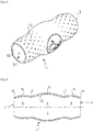
- the manual garlic peeler accessory illustrated on figures 1 and 2 comprises a tubular body 1 having a first open end 2, a second open end 3 opposite to the first open end 2, and a hollow interior 4 extending from the first open end 2 to the second open end 3.
- the first open end 2 and the second open end 3 are each configured for the introduction of a clove of garlic into the tubular body 1.
- the tubular body 1 is made of a flexible material allowing the tubular body 1 to deform under the effect of a pressure exerted during use of the garlic peeler accessory.
- the tubular body 1 has for example a wall with a thickness of between 1.5 and 2 mm.
- the tubular body 1 may have a smooth inner face 12 to facilitate cleaning and an at least partially non-smooth outer face 13, to facilitate handling.
- the outer face 13 may for example have several series of cavities, as shown in figure 1 .
- the tubular body 1 is made of food grade elastomeric material, in particular food grade silicone material.
- the flexible material of the tubular body 1 has a hardness of between 50 and 65 Shores A, preferably of between 55 and 60 Shores A.
- the tubular body 1 has a first restriction of section 6 and a second restriction of section 7.
- the first restriction of section 6 is arranged at a distance from the first open end 2.
- the tubular body 1 provides a first working chamber 5 extending between the first section restriction 6 and the second section restriction 7.
- the first section restriction 6 and the second section restriction 7 are each configured for the introduction of. 'a clove of garlic in the first working chamber 5.
- the first working chamber 5 has a first maximum section 15 arranged between the first section restriction 6 and the second section restriction 7.
- the first working chamber 5 advantageously has a regular curvature with a section decreasing on either side of the first maximum section 15 in the direction of the first section restriction 6 and the second section restriction 7.
- the tubular body 1 has a second working chamber 8 arranged between the first section restriction 6 and the first open end 2.
- the second working chamber 8 is delimited by the first section restriction 6 and by a third section restriction 10 of the tubular body 1.
- the second working chamber 8 is configured to house at least the major part of a clove of garlic.
- the second working chamber 8 has a second maximum section 18 arranged between the first section restriction 6 and the third section restriction 10.
- the second working chamber 8 advantageously has a regular curvature with a section decreasing on either side of the second maximum section 18 towards the first section 6 restriction and the third section 10 restriction.
- the first maximum section 15 of the first working chamber 5 is greater than the second maximum section 18 of the second working chamber 8. Furthermore, the third section restriction 10 coincides with the first open end 2.
- the second section restriction 7 is arranged at a distance from the second open end 3.
- the tubular body 1 has a third working chamber 9 arranged between the second section restriction 7 and the second open end 3.
- the third working chamber 9 is delimited by the second section restriction 7 and by a fourth section restriction. 11 of the tubular body 1.
- the third working chamber 9 is configured to house at least the major part of a clove of garlic.
- the third working chamber 9 has a third maximum section 19 arranged between the second section restriction 7 and the fourth section restriction 11.
- the third working chamber 9 advantageously has a regular curvature with a section decreasing on either side of the third maximum section 19 towards the second restriction of section 7 and the fourth restriction of section 11.
- the first maximum section 15 of the first working chamber 5 is greater than the third maximum section 19 of the third working chamber 9
- the fourth section restriction 11 coincides with the second open end 3.
- the second working chamber 8 and the third working chamber 9 are arranged symmetrically with respect to the first working chamber 5.
- the second maximum section 18 and the third section maximum 19 are advantageously identical.
- the tubular body 1 has a geometry of revolution.
- the first section restriction 6 is formed by a first annular constriction
- the second section restriction 7 is formed by a second annular constriction.
- the inner face 12 of the tubular body 1 does not have an internal projection at the level of the first section restriction 6 or the second section restriction 7, but only a convex curvature, which helps to facilitate cleaning of the internal face. 12 of the tubular body 1.
- the first open end 2 is formed by a third annular constriction
- the second open end 3 is formed by a fourth annular constriction.
- the inner face 12 of the tubular body 1 does not have an internal projection at the level of the third section restriction 10 or the fourth section restriction 11, but only a convex curvature, which contributes to facilitate cleaning of the internal face. 12 of the tubular body 1, but also which contributes to a more homogeneous and more predictable deformation of the tubular body.
- the manual garlic peeler accessory illustrated on figures 1 and 2 is used as follows.
- the user introduces at least one clove of garlic into the tubular body 1, through the first open end 2 or through the second open end 3, preferably up to the first working chamber 5.
- the user positions the tubular body. 1 thus filled on a work surface, and rolls it using the palm of the hand.
- the first section restriction 6 and the second section restriction 7 help to contain the garlic clove (s) in the first working chamber 5, while contributing to peeling, due to the shear stress exerted by the section variable of the tubular body on the skin of the garlic cloves, thanks to the adhesion of the flexible material used for the realization of the tubular body 1.
- the second working chamber 8 and the third working chamber 9 make it possible to collect the clove (s) of garlic escaping from the first working chamber 5, the third section restriction 10 and the fourth section restriction 11 helping to contain the clove (s) of garlic in the tubular body 1.
- the garlic cloves have thus less tendency to escape from the tubular body 1.
- the structure of the tubular body 1 open at both ends facilitates cleaning of the manual garlic peeler attachment. This makes it easier to use the manual garlic peeler.
- At least the first open end 2, respectively at least the second open end 3, is configured for the introduction of a clove of garlic into the tubular body 1.
- at least the first section restriction 6 , respectively at least the second section restriction 7 is configured for the introduction of a clove of garlic into the first working chamber 5.
- the tubular body 1 does not necessarily have a third working chamber configured to house at least the major part of a clove of garlic.
- the second section restriction 7 can be confused with the second open end 3.
- the second section restriction 7 can extend away from the second open end 3 without forming a working chamber configured to. accommodate at least the major part of a clove of garlic.
Landscapes
- Engineering & Computer Science (AREA)
- Food Science & Technology (AREA)
- Food-Manufacturing Devices (AREA)
Abstract
Description
- La présente invention concerne de manière générale le domaine des accessoires de préparation culinaire.
- La présente invention concerne plus particulièrement un accessoire pèle-ail manuel prévu pour faciliter le retrait de l'enveloppe extérieure d'une ou de plusieurs gousses d'ail.
- Il est connu du document
WO9706701 - Le document
CN204683289U propose de réaliser un accessoire pèle-ail manuel dans lequel le corps tubulaire forme une chambre de travail s'étendant entre une première restriction de section et une deuxième restriction de section agencées chacune à distance des extrémités ouvertes. Ces dispositions contribuent à améliorer la rétention des gousses d'ail à l'intérieur de la chambre de travail, toutefois la distance entre chacune des restrictions de section et l'extrémité ouverte adjacente est faible, de sorte que cette amélioration est limitée. De plus la surface intérieure du corps tubulaire présente des picots, ce qui rend l'accessoire pèle-ail difficile à nettoyer. - Un objet de la présente invention est de proposer un accessoire pèle-ail manuel du type précité qui soit efficace et facile à utiliser.
- Un objet de la présente invention est de proposer un accessoire pèle-ail manuel du type précité qui soit facile à réaliser.
- Ces objets sont atteints avec un accessoire pèle-ail manuel comportant un corps tubulaire ayant une première extrémité ouverte, une deuxième extrémité ouverte opposée à la première extrémité ouverte, et un intérieur creux s'étendant de la première extrémité ouverte à la deuxième extrémité ouverte, le corps tubulaire étant réalisé en matériau flexible permettant au corps tubulaire de se déformer sous l'effet d'une pression exercée lors d'une utilisation de l'accessoire pèle-ail, le corps tubulaire ménageant une première chambre de travail configurée pour loger au moins une gousse d'ail, le corps tubulaire présentant une première restriction de section agencée à distance de la première extrémité ouverte et une deuxième restriction de section, la première chambre de travail s'étendant entre la première restriction de section et la deuxième restriction de section, du fait que le corps tubulaire présente une deuxième chambre de travail configurée pour loger au moins la majeure partie d'une gousse d'ail, la deuxième chambre de travail étant agencée entre la première restriction de section et la première extrémité ouverte, la deuxième chambre de travail étant délimitée par la première restriction de section et par une troisième restriction de section. Ainsi lorsqu'une gousse d'ail s'échappe de la première chambre de travail par la première restriction de section, cette gousse d'ail peut être retenue par la troisième restriction de section dans la deuxième chambre de travail, même si une extrémité de ladite gousse d'ail tend à commencer à traverser la première extrémité ouverte. Les gousses d'ail introduites dans le corps tubulaire sont davantage confinées à l'intérieur du corps tubulaire et s'échappent moins par la première extrémité ouverte. La présence de deux extrémités ouvertes facilite la réalisation de l'accessoire ainsi que l'utilisation de l'accessoire. Les deux extrémités ouvertes permettent de mieux contrôler la déformation de l'accessoire lorsque l'utilisateur fait rouler sur un support approprié le corps tubulaire contenant une ou plusieurs gousses d'ail. L'utilisateur peut facilement retirer les gousses d'ail pelées ainsi que les pelures. Le nettoyage est également facilité par la configuration tubulaire de l'accessoire.
- Avantageusement alors, la troisième restriction de section est confondue avec la première extrémité ouverte. Cette disposition permet de simplifier la réalisation de l'accessoire pèle-ail.
- Avantageusement encore, une première section maximale de la première chambre de travail est supérieure à une deuxième section maximale de la deuxième chambre de travail. L'utilisateur peut ainsi loger préférentiellement la ou les gousses d'ail à éplucher dans la première chambre de travail, et faire rouler l'accessoire en dirigeant préférentiellement la ou les gousses d'ail vers la première restriction séparant la première chambre de travail de la deuxième chambre de travail.
- Avantageusement encore, la deuxième restriction de section est agencée à distance de la deuxième extrémité ouverte, et le corps tubulaire présente une troisième chambre de travail configurée pour loger au moins la majeure partie d'une gousse d'ail, la troisième chambre de travail étant agencée entre la deuxième restriction de section et la deuxième extrémité ouverte, la troisième chambre de travail étant délimitée par la deuxième restriction de section et par une quatrième restriction de section. Cette disposition permet de mieux utiliser la première chambre de travail en facilitant la rétention des gousses d'ail s'échappant de la première chambre de travail par la première restriction de section ou par la deuxième restriction de section. L'utilisateur palpant la présence de gousses d'ail dans la deuxième chambre de travail ou dans la troisième chambre de travail, ou voyant des gousses d'ail commencer à sortir par la première extrémité ouverte ou par la deuxième extrémité ouverte peut adapter la position de sa main sur le corps tubulaire pour ramener lesdites gousses d'ail vers la première chambre de travail.
- Avantageusement alors, la quatrième restriction de section est confondue avec la deuxième extrémité ouverte. Cette disposition permet de simplifier la réalisation de l'accessoire pèle-ail.
- Avantageusement encore, une première section maximale de la première chambre de travail est supérieure à une troisième section maximale de la troisième chambre de travail. L'utilisateur peut ainsi loger préférentiellement la ou les gousses d'ail à éplucher dans la première chambre de travail, et faire rouler l'accessoire en dirigeant la ou les gousses d'ail vers la première restriction séparant la première chambre de travail de la deuxième chambre de travail ou vers la deuxième restriction séparant la première chambre de travail de la troisième chambre de travail.
- Avantageusement encore, la deuxième chambre de travail et la troisième chambre de travail sont agencées de manière symétrique par rapport à la première chambre de travail. Cette disposition permet de simplifier l'utilisation de l'accessoire pèle-ail, la symétrie d'agencement rendant plus prévisible le comportement de l'accessoire pèle-ail lors de sa déformation.
- Avantageusement encore, la première restriction de section est formée par un premier rétreint annulaire. Cette disposition permet de faciliter l'utilisation de l'accessoire pèle-ail en rendant plus régulière la déformation de l'accessoire pèle-ail au niveau de la première restriction de section lors du roulement de l'accessoire pèle-ail sur le plan de travail.
- Avantageusement encore, la deuxième restriction de section est formée par un deuxième rétreint annulaire. Cette disposition permet de faciliter l'utilisation de l'accessoire pèle-ail en rendant plus régulière la déformation de l'accessoire pèle-ail au niveau de la deuxième restriction de section lors du roulement de l'accessoire pèle-ail sur le plan de travail.
- Avantageusement encore, le corps tubulaire présente une face intérieure lisse. Cette disposition permet de faciliter le nettoyage de l'accessoire pèle-ail. Cette disposition contribue également à simplifier la réalisation de l'accessoire pèle-ail.
- Selon une forme de réalisation, le corps tubulaire est réalisé en matériau élastomère de qualité alimentaire.
- Selon une forme de réalisation, le corps tubulaire est réalisé en matériau silicone de qualité alimentaire.
- Selon une forme de réalisation, le matériau flexible du corps tubulaire présente une dureté comprise entre 50 et 65 Shores A, de préférence comprise entre 55 et 60 Shores A.
- Avantageusement encore, le corps tubulaire présente une géométrie de révolution. Cette disposition permet de faciliter l'utilisation de l'accessoire pèle-ail en rendant plus régulière la déformation de l'accessoire pèle-ail lors du roulement de l'accessoire pèle-ail sur le plan de travail.
- Avantageusement encore, le corps tubulaire présente une paroi d'épaisseur comprise entre 1,5 et 2 mm.
- D'autres caractéristiques et avantages de la présente invention apparaîtront plus clairement à la lecture de la description détaillée qui suit d'un exemple de réalisation, pris à titre nullement limitatif, illustré dans les figures annexées, dans lesquelles :
- La
figure 1 représente une vue en perspective d'un exemple de réalisation d'un accessoire pèle-ail manuel selon l'invention. - La
figure 2 représente une vue en coupe longitudinale de l'exemple de réalisation d'un accessoire pèle-ail manuel selon l'invention illustré sur lafigure 1 . - L'accessoire pèle-ail manuel illustré sur les
figures 1 et 2 comporte un corps tubulaire 1 ayant une première extrémité ouverte 2, une deuxième extrémité ouverte 3 opposée à la première extrémité ouverte 2, et un intérieur creux 4 s'étendant de la première extrémité ouverte 2 à la deuxième extrémité ouverte 3. La première extrémité ouverte 2 et la deuxième extrémité ouverte 3 sont chacune configurée pour l'introduction d'une gousse d'ail dans le corps tubulaire 1. - Le corps tubulaire 1 est réalisé en matériau flexible permettant au corps tubulaire 1 de se déformer sous l'effet d'une pression exercée lors d'une utilisation de l'accessoire pèle-ail. Le corps tubulaire 1 présente par exemple une paroi d'épaisseur comprise entre 1,5 et 2 mm.
- Le corps tubulaire 1 peut présenter une face intérieure 12 lisse pour faciliter le nettoyage et une face extérieure 13 au moins partiellement non lisse, pour faciliter la tenue en main. La face extérieure 13 peut présenter par exemple plusieurs séries de cavité, tel que représenté sur la
figure 1 . - Le corps tubulaire 1 est réalisé en matériau élastomère de qualité alimentaire, notamment en matériau silicone de qualité alimentaire. Avantageusement, le matériau flexible du corps tubulaire 1 présente une dureté comprise entre 50 et 65 Shores A, de préférence comprise entre 55 et 60 Shores A.
- Tel que mieux visible sur la
figure 2 , le corps tubulaire 1 présente une première restriction de section 6 et une deuxième restriction de section 7. La première restriction de section 6 est agencée à distance de la première extrémité ouverte 2. - Le corps tubulaire 1 ménage une première chambre de travail 5 s'étendant entre la première restriction de section 6 et la deuxième restriction de section 7. La première restriction de section 6 et la deuxième restriction de section 7 sont chacune configurée pour l'introduction d'une gousse d'ail dans la première chambre de travail 5. La première chambre de travail 5 présente une première section maximale 15 agencée entre la première restriction de section 6 et la deuxième restriction de section 7. La première chambre de travail 5 présente avantageusement une courbure régulière avec une section diminuant de part et d'autre de la première section maximale 15 en direction de la première restriction de section 6 et de la deuxième restriction de section 7.
- Tel que bien visible sur la
figure 2 , le corps tubulaire 1 présente une deuxième chambre de travail 8 agencée entre la première restriction de section 6 et la première extrémité ouverte 2. La deuxième chambre de travail 8 est délimitée par la première restriction de section 6 et par une troisième restriction de section 10 du corps tubulaire 1. La deuxième chambre de travail 8 est configurée pour loger au moins la majeure partie d'une gousse d'ail. La deuxième chambre de travail 8 présente une deuxième section maximale 18 agencée entre la première restriction de section 6 et la troisième restriction de section 10. La deuxième chambre de travail 8 présente avantageusement une courbure régulière avec une section diminuant de part et d'autre de la deuxième section maximale 18 en direction de la première restriction de section 6 et de la troisième restriction de section 10. - Plus particulièrement dans l'exemple de réalisation illustré sur les figures, la première section maximale 15 de la première chambre de travail 5 est supérieure à la deuxième section maximale 18 de la deuxième chambre de travail 8. Par ailleurs, la troisième restriction de section 10 est confondue avec la première extrémité ouverte 2.
- Plus particulièrement dans l'exemple de réalisation illustré sur les figures, la deuxième restriction de section 7 est agencée à distance de la deuxième extrémité ouverte 3. Le corps tubulaire 1 présente une troisième chambre de travail 9 agencée entre la deuxième restriction de section 7 et la deuxième extrémité ouverte 3. La troisième chambre de travail 9 est délimitée par la deuxième restriction de section 7 et par une quatrième restriction de section 11 du corps tubulaire 1. La troisième chambre de travail 9 est configurée pour loger au moins la majeure partie d'une gousse d'ail. La troisième chambre de travail 9 présente une troisième section maximale 19 agencée entre la deuxième restriction de section 7 et la quatrième restriction de section 11. La troisième chambre de travail 9 présente avantageusement une courbure régulière avec une section diminuant de part et d'autre de la troisième section maximale 19 en direction de la deuxième restriction de section 7 et de la quatrième restriction de section 11. La première section maximale 15 de la première chambre de travail 5 est supérieure à la troisième section maximale 19 de la troisième chambre de travail 9. Par ailleurs, la quatrième restriction de section 11 est confondue avec la deuxième extrémité ouverte 3.
- Plus particulièrement dans l'exemple de réalisation illustré sur les figures, la deuxième chambre de travail 8 et la troisième chambre de travail 9 sont agencées de manière symétrique par rapport à la première chambre de travail 5. La deuxième section maximale 18 et la troisième section maximale 19 sont avantageusement identiques.
- Plus particulièrement dans l'exemple de réalisation illustré sur les figures, le corps tubulaire 1 présente une géométrie de révolution. La première restriction de section 6 est formée par un premier rétreint annulaire, et la deuxième restriction de section 7 est formée par un deuxième rétreint annulaire. Ainsi la face intérieure 12 du corps tubulaire 1 ne présente pas de saillie interne au niveau de la première restriction de section 6 ou de la deuxième restriction de section 7, mais seulement une courbure convexe, ce qui contribue à faciliter le nettoyage de la face intérieure 12 du corps tubulaire 1. La première extrémité ouverte 2 est formée par un troisième rétreint annulaire, et la deuxième extrémité ouverte 3 est formée par un quatrième rétreint annulaire. Ainsi la face intérieure 12 du corps tubulaire 1 ne présente pas de saillie interne au niveau de la troisième restriction de section 10 ou de la quatrième restriction de section 11, mais seulement une courbure convexe, ce qui contribue à faciliter le nettoyage de la face intérieure 12 du corps tubulaire 1, mais aussi ce qui contribue à une déformation plus homogène et plus prévisible du corps tubulaire.
- L'accessoire pèle-ail manuel illustré sur les
figures 1 et 2 s'utilise de la manière suivante. L'utilisateur introduit au moins une gousse d'ail dans le corps tubulaire 1, par la première extrémité ouverte 2 ou par la deuxième extrémité ouverte 3, de préférence jusqu'à la première chambre de travail 5. L'utilisateur positionne le corps tubulaire 1 ainsi rempli sur un plan de travail, et le fait rouler en utilisant la paume de la main. La première restriction de section 6 et la deuxième restriction de section 7 contribuent à contenir la ou les gousses d'ail dans la première chambre de travail 5, tout en contribuant à l'épluchage, du fait de la contrainte de cisaillement exercée par la section variable du corps tubulaire sur la peau des gousses d'ail, grâce à l'adhérence du matériau flexible utilisé pour la réalisation du corps tubulaire 1. La deuxième chambre de travail 8 et la troisième chambre de travail 9 permettent de recueillir la ou les gousses d'ail s'échappant de la première chambre de travail 5, la troisième restriction de section 10 et la quatrième restriction de section 11 contribuant à contenir la ou les gousses d'ail dans le corps tubulaire 1. Les gousses d'ail ont ainsi moins tendance à s'échapper du corps tubulaire 1. La structure du corps tubulaire 1 ouverte aux deux extrémités facilite le nettoyage de l'accessoire pèle ail manuel. L'utilisation de l'accessoire pèle-ail manuel est ainsi facilitée. - A titre de variante, au moins la première extrémité ouverte 2, respectivement au moins la deuxième extrémité ouverte 3, est configurée pour l'introduction d'une gousse d'ail dans le corps tubulaire 1. Alors au moins la première restriction de section 6, respectivement au moins la deuxième restriction de section 7 est configurée pour l'introduction d'une gousse d'ail dans la première chambre de travail 5.
- A titre de variante, le corps tubulaire 1 ne présente pas nécessairement une troisième chambre de travail configurée pour loger au moins la majeure partie d'une gousse d'ail. Si désiré, la deuxième restriction de section 7 peut être confondue avec la deuxième extrémité ouverte 3. En alternative, la deuxième restriction de section 7 peut s'étendre à distance de la deuxième extrémité ouverte 3 sans pour autant former une chambre de travail configurée pour loger au moins la majeure partie d'une gousse d'ail.
- La présente invention n'est nullement limitée à l'exemple de réalisation décrit et à ses variantes, mais englobe de nombreuses modifications dans le cadre des revendications.
Claims (15)
- Accessoire pèle-ail manuel comportant un corps tubulaire (1) ayant une première extrémité ouverte (2), une deuxième extrémité ouverte (3) opposée à la première extrémité ouverte (2), et un intérieur creux (4) s'étendant de la première extrémité ouverte (2) à la deuxième extrémité ouverte (3), le corps tubulaire (1) étant réalisé en matériau flexible permettant au corps tubulaire (1) de se déformer sous l'effet d'une pression exercée lors d'une utilisation de l'accessoire pèle-ail, le corps tubulaire (1) ménageant une première chambre de travail (5) configurée pour loger au moins une gousse d'ail, le corps tubulaire (1) présentant une première restriction de section (6) agencée à distance de la première extrémité ouverte (2) et une deuxième restriction de section (7), la première chambre de travail (5) s'étendant entre la première restriction de section (6) et la deuxième restriction de section (7), caractérisé en ce que le corps tubulaire (1) présente une deuxième chambre de travail (8) configurée pour loger au moins la majeure partie d'une gousse d'ail, la deuxième chambre de travail (8) étant agencée entre la première restriction de section (6) et la première extrémité ouverte (2), la deuxième chambre de travail (8) étant délimitée par la première restriction de section (6) et par une troisième restriction de section (10).
- Accessoire pèle-ail manuel selon la revendication 1, caractérisé en ce que la troisième restriction de section (10) est confondue avec la première extrémité ouverte (2).
- Accessoire pèle-ail manuel selon l'une des revendications 1 ou 2, caractérisé en ce qu'une première section maximale (15) de la première chambre de travail (5) est supérieure à une deuxième section maximale (18) de la deuxième chambre de travail (8).
- Accessoire pèle-ail manuel selon l'une des revendications 1 à 3, caractérisé en ce que la deuxième restriction de section (7) est agencée à distance de la deuxième extrémité ouverte (3), et en ce que le corps tubulaire (1) présente une troisième chambre de travail (9) configurée pour loger au moins la majeure partie d'une gousse d'ail, la troisième chambre de travail (9) étant agencée entre la deuxième restriction de section (7) et la deuxième extrémité ouverte (3), la troisième chambre de travail (9) étant délimitée par la deuxième restriction de section (7) et par une quatrième restriction de section (11).
- Accessoire pèle-ail manuel selon la revendication 4, caractérisé en ce que la quatrième restriction de section (11) est confondue avec la deuxième extrémité ouverte (3).
- Accessoire pèle-ail manuel selon l'une des revendications 4 ou 5, caractérisé en ce qu'une première section maximale (15) de la première chambre de travail (5) est supérieure à une troisième section maximale (19) de la troisième chambre de travail (9).
- Accessoire pèle-ail manuel selon l'une des revendications 4 à 6, caractérisé en ce que la deuxième chambre de travail (8) et la troisième chambre de travail (9) sont agencées de manière symétrique par rapport à la première chambre de travail (5).
- Accessoire pèle-ail manuel selon l'une des revendications 1 à 7, caractérisé en ce que la première restriction de section (6) est formée par un premier rétreint annulaire et/ou en ce que la deuxième restriction de section (7) est formée par un deuxième rétreint annulaire.
- Accessoire pèle-ail manuel selon l'une des revendications 1 à 8, caractérisé en ce que la première extrémité ouverte (2) est formée par un troisième rétreint annulaire et/ou en ce que la deuxième extrémité ouverte (3) est formée par un quatrième rétreint annulaire.
- Accessoire pèle-ail manuel selon l'une des revendications 1 à 9, caractérisé en ce que le corps tubulaire (1) présente une face intérieure (12) lisse.
- Accessoire pèle-ail manuel selon l'une des revendications 1 à 10, caractérisé en ce que le corps tubulaire (1) est réalisé en matériau élastomère de qualité alimentaire.
- Accessoire pèle-ail manuel selon l'une des revendications 1 à 11, caractérisé en ce que le corps tubulaire (1) est réalisé en matériau silicone de qualité alimentaire.
- Accessoire pèle-ail manuel selon l'une des revendications 1 à 12, caractérisé en ce que le matériau flexible du corps tubulaire (1) présente une dureté comprise entre 50 et 65 Shores A, de préférence comprise entre 55 et 60 Shores A.
- Accessoire pèle-ail manuel selon l'une des revendications 1 à 13, caractérisé en ce que le corps tubulaire (1) présente une géométrie de révolution.
- Accessoire pèle-ail manuel selon l'une des revendications 1 à 14, caractérisé en ce que le corps tubulaire (1) présente une paroi d'épaisseur comprise entre 1,5 et 2 mm.
Applications Claiming Priority (1)
| Application Number | Priority Date | Filing Date | Title |
|---|---|---|---|
| FR1902626A FR3093629B1 (fr) | 2019-03-14 | 2019-03-14 | Accessoire pele-ail manuel |
Publications (2)
| Publication Number | Publication Date |
|---|---|
| EP3708035A1 true EP3708035A1 (fr) | 2020-09-16 |
| EP3708035B1 EP3708035B1 (fr) | 2022-04-27 |
Family
ID=67384000
Family Applications (1)
| Application Number | Title | Priority Date | Filing Date |
|---|---|---|---|
| EP20162869.0A Active EP3708035B1 (fr) | 2019-03-14 | 2020-03-13 | Accessoire pèle-ail manuel |
Country Status (3)
| Country | Link |
|---|---|
| EP (1) | EP3708035B1 (fr) |
| CN (1) | CN111685571B (fr) |
| FR (1) | FR3093629B1 (fr) |
Citations (4)
| Publication number | Priority date | Publication date | Assignee | Title |
|---|---|---|---|---|
| US5573803A (en) * | 1994-06-06 | 1996-11-12 | Omessi; Benjamin | Vegetable peeler |
| GB2315990A (en) * | 1996-08-03 | 1998-02-18 | Benjamin Beveridge | Hand operated garlic peeler |
| CN204683289U (zh) | 2015-05-27 | 2015-10-07 | 郑珂 | 手掌磁疗按摩剥蒜器 |
| US20180020863A1 (en) * | 2016-07-13 | 2018-01-25 | Progressive International Corporation | Garlic peeler |
Family Cites Families (6)
| Publication number | Priority date | Publication date | Assignee | Title |
|---|---|---|---|---|
| CN2593691Y (zh) * | 2003-01-20 | 2003-12-24 | 王建鹏 | 蒜瓣剥皮器 |
| WO2006013562A2 (fr) * | 2004-08-05 | 2006-02-09 | Tichkum Distribution Of Advanced Consumer Products Ltd | Eplucheur d'ail |
| CN2778134Y (zh) * | 2005-03-01 | 2006-05-10 | 王长林 | 大蒜剥皮器 |
| CN201295119Y (zh) * | 2008-07-24 | 2009-08-26 | 浙江苏泊尔橡塑制品有限公司 | 一种大蒜剥皮器 |
| KR101591514B1 (ko) * | 2013-11-13 | 2016-02-03 | 최병철 | 마늘 박피기 |
| US10080382B2 (en) * | 2014-01-28 | 2018-09-25 | Garlicshaker, Inc. | Method for removing an outer surface of produce |
-
2019
- 2019-03-14 FR FR1902626A patent/FR3093629B1/fr active Active
-
2020
- 2020-03-13 CN CN202010173646.5A patent/CN111685571B/zh active Active
- 2020-03-13 EP EP20162869.0A patent/EP3708035B1/fr active Active
Patent Citations (5)
| Publication number | Priority date | Publication date | Assignee | Title |
|---|---|---|---|---|
| US5573803A (en) * | 1994-06-06 | 1996-11-12 | Omessi; Benjamin | Vegetable peeler |
| WO1997006701A1 (fr) | 1994-06-06 | 1997-02-27 | Benjamin Omessi | Eplucheur a legumes |
| GB2315990A (en) * | 1996-08-03 | 1998-02-18 | Benjamin Beveridge | Hand operated garlic peeler |
| CN204683289U (zh) | 2015-05-27 | 2015-10-07 | 郑珂 | 手掌磁疗按摩剥蒜器 |
| US20180020863A1 (en) * | 2016-07-13 | 2018-01-25 | Progressive International Corporation | Garlic peeler |
Also Published As
| Publication number | Publication date |
|---|---|
| CN111685571A (zh) | 2020-09-22 |
| CN111685571B (zh) | 2023-08-08 |
| FR3093629B1 (fr) | 2022-02-18 |
| FR3093629A1 (fr) | 2020-09-18 |
| EP3708035B1 (fr) | 2022-04-27 |
Similar Documents
| Publication | Publication Date | Title |
|---|---|---|
| EP3324901B1 (fr) | Coupe menstruelle ergonomique | |
| FR2855420A3 (fr) | Bouchon pour oreille | |
| FR3010245A1 (fr) | Assemblage electrique a connexion etanche | |
| CA3056322A1 (fr) | Seringue a centre de gravite optimise | |
| CA3004808A1 (fr) | Seringue | |
| FR2698781A1 (fr) | Dispositif destiné à remédier aux incontinences urinaires légères chez la femme. | |
| EP3708035B1 (fr) | Accessoire pèle-ail manuel | |
| FR2947153A1 (fr) | Enveloppe interchangeable pour casques et casques munis d'une telle enveloppe, permettant d'attenuer les effets traumatisants des chocs rotationnels | |
| FR2834447A3 (fr) | Element pout l'oreille | |
| FR2579456A1 (fr) | Protege-tympan | |
| EP2923808A1 (fr) | Evideur de fruits ou de legumes | |
| FR2990353A1 (fr) | Perfectionnement pour seringue hypodermique | |
| CH359330A (fr) | Raccordement d'éléments tubulaires | |
| FR2982762A1 (fr) | Appareil de brossage de dents a multiples systemes rotatifs de brossage | |
| WO2014076426A2 (fr) | Stylo-plume | |
| EP3007597B1 (fr) | Boitier d'appareil électroménager comportant au moins un pied d'appui | |
| FR2886709A1 (fr) | Connecteur pour le transfert de liquide, notamment dans le domaine medical | |
| WO2019145641A1 (fr) | Kit de protection vulvaire et anale et procédé d'installation d'une telle protection | |
| EP0544901B1 (fr) | Assemblage etanche amovible d'une botte ou d'un gant a l'extremite libre du membre correspondant d'un vetement de protection | |
| FR3136341A1 (fr) | Pinceau d’application de produit cosmétique à manche déformable | |
| BE1023098B1 (fr) | Poignée amovible pour ustensiles | |
| FR2658704A1 (fr) | Brosse a manche deformable. | |
| WO2019170975A1 (fr) | Dispositif applicateur de produit cosmétique | |
| EP1495701B1 (fr) | Dispositif de joint pour ustensile de cuisson dit couscoussier | |
| FR2509606A3 (fr) | Condom |
Legal Events
| Date | Code | Title | Description |
|---|---|---|---|
| PUAI | Public reference made under article 153(3) epc to a published international application that has entered the european phase |
Free format text: ORIGINAL CODE: 0009012 |
|
| STAA | Information on the status of an ep patent application or granted ep patent |
Free format text: STATUS: THE APPLICATION HAS BEEN PUBLISHED |
|
| AK | Designated contracting states |
Kind code of ref document: A1 Designated state(s): AL AT BE BG CH CY CZ DE DK EE ES FI FR GB GR HR HU IE IS IT LI LT LU LV MC MK MT NL NO PL PT RO RS SE SI SK SM TR |
|
| AX | Request for extension of the european patent |
Extension state: BA ME |
|
| STAA | Information on the status of an ep patent application or granted ep patent |
Free format text: STATUS: REQUEST FOR EXAMINATION WAS MADE |
|
| 17P | Request for examination filed |
Effective date: 20210315 |
|
| RBV | Designated contracting states (corrected) |
Designated state(s): AL AT BE BG CH CY CZ DE DK EE ES FI FR GB GR HR HU IE IS IT LI LT LU LV MC MK MT NL NO PL PT RO RS SE SI SK SM TR |
|
| STAA | Information on the status of an ep patent application or granted ep patent |
Free format text: STATUS: EXAMINATION IS IN PROGRESS |
|
| 17Q | First examination report despatched |
Effective date: 20210428 |
|
| GRAP | Despatch of communication of intention to grant a patent |
Free format text: ORIGINAL CODE: EPIDOSNIGR1 |
|
| STAA | Information on the status of an ep patent application or granted ep patent |
Free format text: STATUS: GRANT OF PATENT IS INTENDED |
|
| INTG | Intention to grant announced |
Effective date: 20211207 |
|
| GRAS | Grant fee paid |
Free format text: ORIGINAL CODE: EPIDOSNIGR3 |
|
| GRAA | (expected) grant |
Free format text: ORIGINAL CODE: 0009210 |
|
| STAA | Information on the status of an ep patent application or granted ep patent |
Free format text: STATUS: THE PATENT HAS BEEN GRANTED |
|
| AK | Designated contracting states |
Kind code of ref document: B1 Designated state(s): AL AT BE BG CH CY CZ DE DK EE ES FI FR GB GR HR HU IE IS IT LI LT LU LV MC MK MT NL NO PL PT RO RS SE SI SK SM TR |
|
| REG | Reference to a national code |
Ref country code: GB Ref legal event code: FG4D Free format text: NOT ENGLISH |
|
| REG | Reference to a national code |
Ref country code: CH Ref legal event code: EP |
|
| REG | Reference to a national code |
Ref country code: AT Ref legal event code: REF Ref document number: 1486263 Country of ref document: AT Kind code of ref document: T Effective date: 20220515 |
|
| REG | Reference to a national code |
Ref country code: DE Ref legal event code: R096 Ref document number: 602020002789 Country of ref document: DE |
|
| REG | Reference to a national code |
Ref country code: IE Ref legal event code: FG4D Free format text: LANGUAGE OF EP DOCUMENT: FRENCH |
|
| REG | Reference to a national code |
Ref country code: LT Ref legal event code: MG9D |
|
| REG | Reference to a national code |
Ref country code: NL Ref legal event code: MP Effective date: 20220427 |
|
| REG | Reference to a national code |
Ref country code: AT Ref legal event code: MK05 Ref document number: 1486263 Country of ref document: AT Kind code of ref document: T Effective date: 20220427 |
|
| PG25 | Lapsed in a contracting state [announced via postgrant information from national office to epo] |
Ref country code: NL Free format text: LAPSE BECAUSE OF FAILURE TO SUBMIT A TRANSLATION OF THE DESCRIPTION OR TO PAY THE FEE WITHIN THE PRESCRIBED TIME-LIMIT Effective date: 20220427 |
|
| PG25 | Lapsed in a contracting state [announced via postgrant information from national office to epo] |
Ref country code: SE Free format text: LAPSE BECAUSE OF FAILURE TO SUBMIT A TRANSLATION OF THE DESCRIPTION OR TO PAY THE FEE WITHIN THE PRESCRIBED TIME-LIMIT Effective date: 20220427 Ref country code: PT Free format text: LAPSE BECAUSE OF FAILURE TO SUBMIT A TRANSLATION OF THE DESCRIPTION OR TO PAY THE FEE WITHIN THE PRESCRIBED TIME-LIMIT Effective date: 20220829 Ref country code: NO Free format text: LAPSE BECAUSE OF FAILURE TO SUBMIT A TRANSLATION OF THE DESCRIPTION OR TO PAY THE FEE WITHIN THE PRESCRIBED TIME-LIMIT Effective date: 20220727 Ref country code: LT Free format text: LAPSE BECAUSE OF FAILURE TO SUBMIT A TRANSLATION OF THE DESCRIPTION OR TO PAY THE FEE WITHIN THE PRESCRIBED TIME-LIMIT Effective date: 20220427 Ref country code: HR Free format text: LAPSE BECAUSE OF FAILURE TO SUBMIT A TRANSLATION OF THE DESCRIPTION OR TO PAY THE FEE WITHIN THE PRESCRIBED TIME-LIMIT Effective date: 20220427 Ref country code: GR Free format text: LAPSE BECAUSE OF FAILURE TO SUBMIT A TRANSLATION OF THE DESCRIPTION OR TO PAY THE FEE WITHIN THE PRESCRIBED TIME-LIMIT Effective date: 20220728 Ref country code: FI Free format text: LAPSE BECAUSE OF FAILURE TO SUBMIT A TRANSLATION OF THE DESCRIPTION OR TO PAY THE FEE WITHIN THE PRESCRIBED TIME-LIMIT Effective date: 20220427 Ref country code: ES Free format text: LAPSE BECAUSE OF FAILURE TO SUBMIT A TRANSLATION OF THE DESCRIPTION OR TO PAY THE FEE WITHIN THE PRESCRIBED TIME-LIMIT Effective date: 20220427 Ref country code: BG Free format text: LAPSE BECAUSE OF FAILURE TO SUBMIT A TRANSLATION OF THE DESCRIPTION OR TO PAY THE FEE WITHIN THE PRESCRIBED TIME-LIMIT Effective date: 20220727 Ref country code: AT Free format text: LAPSE BECAUSE OF FAILURE TO SUBMIT A TRANSLATION OF THE DESCRIPTION OR TO PAY THE FEE WITHIN THE PRESCRIBED TIME-LIMIT Effective date: 20220427 |
|
| PG25 | Lapsed in a contracting state [announced via postgrant information from national office to epo] |
Ref country code: RS Free format text: LAPSE BECAUSE OF FAILURE TO SUBMIT A TRANSLATION OF THE DESCRIPTION OR TO PAY THE FEE WITHIN THE PRESCRIBED TIME-LIMIT Effective date: 20220427 Ref country code: PL Free format text: LAPSE BECAUSE OF FAILURE TO SUBMIT A TRANSLATION OF THE DESCRIPTION OR TO PAY THE FEE WITHIN THE PRESCRIBED TIME-LIMIT Effective date: 20220427 Ref country code: LV Free format text: LAPSE BECAUSE OF FAILURE TO SUBMIT A TRANSLATION OF THE DESCRIPTION OR TO PAY THE FEE WITHIN THE PRESCRIBED TIME-LIMIT Effective date: 20220427 Ref country code: IS Free format text: LAPSE BECAUSE OF FAILURE TO SUBMIT A TRANSLATION OF THE DESCRIPTION OR TO PAY THE FEE WITHIN THE PRESCRIBED TIME-LIMIT Effective date: 20220827 |
|
| REG | Reference to a national code |
Ref country code: DE Ref legal event code: R097 Ref document number: 602020002789 Country of ref document: DE |
|
| PG25 | Lapsed in a contracting state [announced via postgrant information from national office to epo] |
Ref country code: SM Free format text: LAPSE BECAUSE OF FAILURE TO SUBMIT A TRANSLATION OF THE DESCRIPTION OR TO PAY THE FEE WITHIN THE PRESCRIBED TIME-LIMIT Effective date: 20220427 Ref country code: SK Free format text: LAPSE BECAUSE OF FAILURE TO SUBMIT A TRANSLATION OF THE DESCRIPTION OR TO PAY THE FEE WITHIN THE PRESCRIBED TIME-LIMIT Effective date: 20220427 Ref country code: RO Free format text: LAPSE BECAUSE OF FAILURE TO SUBMIT A TRANSLATION OF THE DESCRIPTION OR TO PAY THE FEE WITHIN THE PRESCRIBED TIME-LIMIT Effective date: 20220427 Ref country code: EE Free format text: LAPSE BECAUSE OF FAILURE TO SUBMIT A TRANSLATION OF THE DESCRIPTION OR TO PAY THE FEE WITHIN THE PRESCRIBED TIME-LIMIT Effective date: 20220427 Ref country code: DK Free format text: LAPSE BECAUSE OF FAILURE TO SUBMIT A TRANSLATION OF THE DESCRIPTION OR TO PAY THE FEE WITHIN THE PRESCRIBED TIME-LIMIT Effective date: 20220427 Ref country code: CZ Free format text: LAPSE BECAUSE OF FAILURE TO SUBMIT A TRANSLATION OF THE DESCRIPTION OR TO PAY THE FEE WITHIN THE PRESCRIBED TIME-LIMIT Effective date: 20220427 |
|
| PLBE | No opposition filed within time limit |
Free format text: ORIGINAL CODE: 0009261 |
|
| STAA | Information on the status of an ep patent application or granted ep patent |
Free format text: STATUS: NO OPPOSITION FILED WITHIN TIME LIMIT |
|
| PG25 | Lapsed in a contracting state [announced via postgrant information from national office to epo] |
Ref country code: AL Free format text: LAPSE BECAUSE OF FAILURE TO SUBMIT A TRANSLATION OF THE DESCRIPTION OR TO PAY THE FEE WITHIN THE PRESCRIBED TIME-LIMIT Effective date: 20220427 |
|
| 26N | No opposition filed |
Effective date: 20230130 |
|
| PG25 | Lapsed in a contracting state [announced via postgrant information from national office to epo] |
Ref country code: SI Free format text: LAPSE BECAUSE OF FAILURE TO SUBMIT A TRANSLATION OF THE DESCRIPTION OR TO PAY THE FEE WITHIN THE PRESCRIBED TIME-LIMIT Effective date: 20220427 |
|
| PG25 | Lapsed in a contracting state [announced via postgrant information from national office to epo] |
Ref country code: MC Free format text: LAPSE BECAUSE OF FAILURE TO SUBMIT A TRANSLATION OF THE DESCRIPTION OR TO PAY THE FEE WITHIN THE PRESCRIBED TIME-LIMIT Effective date: 20220427 |
|
| REG | Reference to a national code |
Ref country code: CH Ref legal event code: PL |
|
| REG | Reference to a national code |
Ref country code: BE Ref legal event code: MM Effective date: 20230331 |
|
| PG25 | Lapsed in a contracting state [announced via postgrant information from national office to epo] |
Ref country code: LU Free format text: LAPSE BECAUSE OF NON-PAYMENT OF DUE FEES Effective date: 20230313 |
|
| REG | Reference to a national code |
Ref country code: IE Ref legal event code: MM4A |
|
| PG25 | Lapsed in a contracting state [announced via postgrant information from national office to epo] |
Ref country code: LI Free format text: LAPSE BECAUSE OF NON-PAYMENT OF DUE FEES Effective date: 20230331 Ref country code: IT Free format text: LAPSE BECAUSE OF FAILURE TO SUBMIT A TRANSLATION OF THE DESCRIPTION OR TO PAY THE FEE WITHIN THE PRESCRIBED TIME-LIMIT Effective date: 20220427 Ref country code: IE Free format text: LAPSE BECAUSE OF NON-PAYMENT OF DUE FEES Effective date: 20230313 Ref country code: CH Free format text: LAPSE BECAUSE OF NON-PAYMENT OF DUE FEES Effective date: 20230331 |
|
| PG25 | Lapsed in a contracting state [announced via postgrant information from national office to epo] |
Ref country code: BE Free format text: LAPSE BECAUSE OF NON-PAYMENT OF DUE FEES Effective date: 20230331 |
|
| PG25 | Lapsed in a contracting state [announced via postgrant information from national office to epo] |
Ref country code: BG Free format text: LAPSE BECAUSE OF FAILURE TO SUBMIT A TRANSLATION OF THE DESCRIPTION OR TO PAY THE FEE WITHIN THE PRESCRIBED TIME-LIMIT Effective date: 20220427 |
|
| GBPC | Gb: european patent ceased through non-payment of renewal fee |
Effective date: 20240313 |
|
| PG25 | Lapsed in a contracting state [announced via postgrant information from national office to epo] |
Ref country code: BG Free format text: LAPSE BECAUSE OF FAILURE TO SUBMIT A TRANSLATION OF THE DESCRIPTION OR TO PAY THE FEE WITHIN THE PRESCRIBED TIME-LIMIT Effective date: 20220427 |
|
| PG25 | Lapsed in a contracting state [announced via postgrant information from national office to epo] |
Ref country code: GB Free format text: LAPSE BECAUSE OF NON-PAYMENT OF DUE FEES Effective date: 20240313 |
|
| PG25 | Lapsed in a contracting state [announced via postgrant information from national office to epo] |
Ref country code: GB Free format text: LAPSE BECAUSE OF NON-PAYMENT OF DUE FEES Effective date: 20240313 |
|
| PGFP | Annual fee paid to national office [announced via postgrant information from national office to epo] |
Ref country code: DE Payment date: 20250313 Year of fee payment: 6 |
|
| PGFP | Annual fee paid to national office [announced via postgrant information from national office to epo] |
Ref country code: FR Payment date: 20250331 Year of fee payment: 6 |
|
| PG25 | Lapsed in a contracting state [announced via postgrant information from national office to epo] |
Ref country code: CY Free format text: LAPSE BECAUSE OF FAILURE TO SUBMIT A TRANSLATION OF THE DESCRIPTION OR TO PAY THE FEE WITHIN THE PRESCRIBED TIME-LIMIT; INVALID AB INITIO Effective date: 20200313 |
|
| PG25 | Lapsed in a contracting state [announced via postgrant information from national office to epo] |
Ref country code: HU Free format text: LAPSE BECAUSE OF FAILURE TO SUBMIT A TRANSLATION OF THE DESCRIPTION OR TO PAY THE FEE WITHIN THE PRESCRIBED TIME-LIMIT; INVALID AB INITIO Effective date: 20200313 |
|
| PG25 | Lapsed in a contracting state [announced via postgrant information from national office to epo] |
Ref country code: TR Free format text: LAPSE BECAUSE OF FAILURE TO SUBMIT A TRANSLATION OF THE DESCRIPTION OR TO PAY THE FEE WITHIN THE PRESCRIBED TIME-LIMIT Effective date: 20220427 |