EP3708027A2 - Modulares befestigungsöffnungsarray - Google Patents
Modulares befestigungsöffnungsarray Download PDFInfo
- Publication number
- EP3708027A2 EP3708027A2 EP20163113.2A EP20163113A EP3708027A2 EP 3708027 A2 EP3708027 A2 EP 3708027A2 EP 20163113 A EP20163113 A EP 20163113A EP 3708027 A2 EP3708027 A2 EP 3708027A2
- Authority
- EP
- European Patent Office
- Prior art keywords
- array
- aperture
- apertures
- aperture array
- array layer
- Prior art date
- Legal status (The legal status is an assumption and is not a legal conclusion. Google has not performed a legal analysis and makes no representation as to the accuracy of the status listed.)
- Withdrawn
Links
- 239000012876 carrier material Substances 0.000 claims abstract description 117
- 239000004744 fabric Substances 0.000 claims description 12
- 229920002681 hypalon Polymers 0.000 claims description 12
- 239000004677 Nylon Substances 0.000 claims description 8
- 229920001778 nylon Polymers 0.000 claims description 8
- 229920003051 synthetic elastomer Polymers 0.000 claims description 4
- 239000005061 synthetic rubber Substances 0.000 claims description 4
- 239000011159 matrix material Substances 0.000 description 138
- 238000000034 method Methods 0.000 description 93
- 230000008878 coupling Effects 0.000 description 46
- 238000010168 coupling process Methods 0.000 description 46
- 238000005859 coupling reaction Methods 0.000 description 46
- 239000000463 material Substances 0.000 description 45
- 239000003365 glass fiber Chemical class 0.000 description 8
- 229920000049 Carbon (fiber) Chemical class 0.000 description 6
- 239000004917 carbon fiber Chemical class 0.000 description 6
- 239000002131 composite material Substances 0.000 description 6
- 239000000835 fiber Substances 0.000 description 6
- 230000003993 interaction Effects 0.000 description 5
- 230000013011 mating Effects 0.000 description 5
- 238000004026 adhesive bonding Methods 0.000 description 4
- -1 for example Substances 0.000 description 4
- 229910052751 metal Inorganic materials 0.000 description 4
- 239000002184 metal Substances 0.000 description 4
- 150000002739 metals Chemical class 0.000 description 4
- VNWKTOKETHGBQD-UHFFFAOYSA-N methane Chemical class C VNWKTOKETHGBQD-UHFFFAOYSA-N 0.000 description 4
- 229920003023 plastic Polymers 0.000 description 4
- 239000004033 plastic Substances 0.000 description 4
- 229920000642 polymer Polymers 0.000 description 4
- 229920001187 thermosetting polymer Polymers 0.000 description 4
- 238000003466 welding Methods 0.000 description 4
- 230000008901 benefit Effects 0.000 description 3
- 239000004593 Epoxy Substances 0.000 description 2
- 229920002334 Spandex Polymers 0.000 description 2
- 229910000831 Steel Inorganic materials 0.000 description 2
- RTAQQCXQSZGOHL-UHFFFAOYSA-N Titanium Chemical compound [Ti] RTAQQCXQSZGOHL-UHFFFAOYSA-N 0.000 description 2
- 229920006397 acrylic thermoplastic Polymers 0.000 description 2
- 230000006978 adaptation Effects 0.000 description 2
- 239000000956 alloy Substances 0.000 description 2
- 229910045601 alloy Inorganic materials 0.000 description 2
- 229910052782 aluminium Inorganic materials 0.000 description 2
- XAGFODPZIPBFFR-UHFFFAOYSA-N aluminium Chemical compound [Al] XAGFODPZIPBFFR-UHFFFAOYSA-N 0.000 description 2
- 239000000969 carrier Substances 0.000 description 2
- 238000005352 clarification Methods 0.000 description 2
- 238000010276 construction Methods 0.000 description 2
- XLJMAIOERFSOGZ-UHFFFAOYSA-M cyanate Chemical compound [O-]C#N XLJMAIOERFSOGZ-UHFFFAOYSA-M 0.000 description 2
- 239000003822 epoxy resin Substances 0.000 description 2
- 239000011151 fibre-reinforced plastic Substances 0.000 description 2
- 239000010408 film Substances 0.000 description 2
- 239000011521 glass Substances 0.000 description 2
- LNEPOXFFQSENCJ-UHFFFAOYSA-N haloperidol Chemical compound C1CC(O)(C=2C=CC(Cl)=CC=2)CCN1CCCC(=O)C1=CC=C(F)C=C1 LNEPOXFFQSENCJ-UHFFFAOYSA-N 0.000 description 2
- 239000004413 injection moulding compound Substances 0.000 description 2
- 238000012986 modification Methods 0.000 description 2
- 230000004048 modification Effects 0.000 description 2
- 239000005011 phenolic resin Substances 0.000 description 2
- 229920001568 phenolic resin Polymers 0.000 description 2
- 229920001084 poly(chloroprene) Polymers 0.000 description 2
- 229920003229 poly(methyl methacrylate) Polymers 0.000 description 2
- 229920000647 polyepoxide Polymers 0.000 description 2
- 229920001225 polyester resin Polymers 0.000 description 2
- 239000004645 polyester resin Substances 0.000 description 2
- 229920001721 polyimide Polymers 0.000 description 2
- 239000009719 polyimide resin Substances 0.000 description 2
- 229920005594 polymer fiber Polymers 0.000 description 2
- 229920001343 polytetrafluoroethylene Polymers 0.000 description 2
- 239000004810 polytetrafluoroethylene Substances 0.000 description 2
- 239000004800 polyvinyl chloride Substances 0.000 description 2
- 229920005989 resin Polymers 0.000 description 2
- 239000011347 resin Substances 0.000 description 2
- 239000004759 spandex Substances 0.000 description 2
- 239000010935 stainless steel Substances 0.000 description 2
- 229910001220 stainless steel Inorganic materials 0.000 description 2
- 239000010959 steel Substances 0.000 description 2
- ISXSCDLOGDJUNJ-UHFFFAOYSA-N tert-butyl prop-2-enoate Chemical compound CC(C)(C)OC(=O)C=C ISXSCDLOGDJUNJ-UHFFFAOYSA-N 0.000 description 2
- 229920005992 thermoplastic resin Polymers 0.000 description 2
- 229910052719 titanium Inorganic materials 0.000 description 2
- 239000010936 titanium Substances 0.000 description 2
- 125000000391 vinyl group Chemical group [H]C([*])=C([H])[H] 0.000 description 2
- 229920002554 vinyl polymer Polymers 0.000 description 2
- XLYOFNOQVPJJNP-UHFFFAOYSA-N water Substances O XLYOFNOQVPJJNP-UHFFFAOYSA-N 0.000 description 2
- 239000002759 woven fabric Substances 0.000 description 2
- 230000008859 change Effects 0.000 description 1
- 230000003247 decreasing effect Effects 0.000 description 1
- 230000007717 exclusion Effects 0.000 description 1
- 238000012913 prioritisation Methods 0.000 description 1
- 230000008569 process Effects 0.000 description 1
- 239000000243 solution Substances 0.000 description 1
- 230000002123 temporal effect Effects 0.000 description 1
Images










Classifications
-
- A—HUMAN NECESSITIES
- A45—HAND OR TRAVELLING ARTICLES
- A45C—PURSES; LUGGAGE; HAND CARRIED BAGS
- A45C13/00—Details; Accessories
- A45C13/001—Accessories
-
- A—HUMAN NECESSITIES
- A45—HAND OR TRAVELLING ARTICLES
- A45F—TRAVELLING OR CAMP EQUIPMENT: SACKS OR PACKS CARRIED ON THE BODY
- A45F3/00—Travelling or camp articles; Sacks or packs carried on the body
- A45F3/04—Sacks or packs carried on the body by means of two straps passing over the two shoulders
- A45F3/06—Sacks or packs carried on the body by means of two straps passing over the two shoulders specially adapted for military purposes
-
- A—HUMAN NECESSITIES
- A45—HAND OR TRAVELLING ARTICLES
- A45C—PURSES; LUGGAGE; HAND CARRIED BAGS
- A45C13/00—Details; Accessories
- A45C13/02—Interior fittings; Means, e.g. inserts, for holding and packing articles
-
- A—HUMAN NECESSITIES
- A45—HAND OR TRAVELLING ARTICLES
- A45C—PURSES; LUGGAGE; HAND CARRIED BAGS
- A45C3/00—Flexible luggage; Handbags
- A45C3/06—Ladies' handbags
- A45C3/08—Handbags provided with removable or washable covers
Definitions
- the present disclosure relates generally to the field of modular attachment systems. More specifically, the presently disclosed systems, methods, and/or apparatuses relates to a modular attachment system having an aperture array.
- MOLLE Modular Lightweight Load-carrying Equipment
- the MOLLE system is a modular system that incorporates the use of corresponding rows of webbing stitched onto a piece of equipment, such as a vest, and the various MOLLE compatible pouches, pockets, and accessories, each accessory having mating rows of stitched webbing. MOLLE compatible pouches, pockets, and accessories of various utility can then be attached or coupled wherever MOLLE webbing exists on the equipment.
- MOLLE-compatible or “MOLLE” system are not used to describe a specific system, but to generically describe accessory attachment systems that utilize interwoven PALS (Pouch Attachment Ladder System) webbing for modular accessory attachment.
- PALS Pouch Attachment Ladder System
- an exemplary MOLLE compatible carrier portion 10 includes a plurality of substantially parallel rows of spaced apart, horizontal carrier webbing elements 23.
- Each of the carrier webbing elements 23 is secured to a backing or carrier material 12, by vertical stitching 24, at spaced apart locations, such that a tunnel segment 27 is formed between the carrier material 12 and the carrier webbing elements 23 between each secured location of the carrier webbing elements 23.
- Each of the tunnel segments 27 is formed substantially perpendicular to a longitudinal axis or direction of the carrier webbing elements 23.
- the MOLLE compatible carrier portion 10, or MOLLE system grid typically consists of horizontal rows of 1 inch (2.5 cm) webbing, spaced 1 inch apart, and attached or coupled to the carrier material 12 at 1.5 inch (3.8 cm) intervals.
- An exemplary accessory 81 includes a plurality of substantially parallel, spaced apart accessory webbing elements 83.
- the accessory webbing elements 83 are spaced apart so as to correspond to the spaces between the spaced apart carrier webbing elements 23.
- the accessory webbing elements 83 are secured to the accessory 81 at spaced apart locations, such that an accessory tunnel segment 87 is formed between the accessory 81 and the accessory webbing element 83 between each secured location of the accessory webbing element 83.
- Each of the accessory tunnel segments 87 is formed substantially perpendicular to a longitudinal direction of the accessory webbing elements 83.
- a strap or coupling element may be interwoven between the aligned tunnel segments 27 and accessory tunnel segments 87 (alternating between horizontal carrier webbing element 23 portions on the host or carrier material 12 and horizontal webbing portions on the accessory 81 ) to removably attach the accessory 81 to the carrier material 12.
- an accessory 81 may be mounted to a variety of carrier materials 12.
- a particular carrier material 12 includes a MOLLE compatible system
- a variety of accessories may be interchangeably mounted to the platform to accommodate a variety of desired configurations.
- MOLLE compatible systems allow, for example, various pouch arrangements to be specifically tailored to a desired configuration and then reconfigured, if desired.
- Various desired pouches, pockets, and accessories can be added and undesired or unnecessary pouches, pockets, or accessories can be removed.
- MOLLE-compatible or “MOLLE” system arrangement has various shortcomings.
- known “MOLLE-compatible” or “MOLLE” systems only allow for attachment of accessories in a single orientation relative to the carrier webbing elements. In most applications, this results in only vertical attachment of accessories to the MOLLE system, i.e., attachment perpendicular to the longitudinal axis, A L , of the carrier webbing elements.
- the modular attachment aperture array of the presently disclosed systems, methods, and/or apparatuses provides an aperture array layer that allows MOLLE-compatible or similar accessories to be attached or coupled to the aperture array layer in a vertical, horizontal, oblique, or diagonal manner, relative to a row, column, or other pattern of spaced apart array apertures.
- the modular attachment aperture array of the present disclosure comprises at least some of a portion of carrier material; and an aperture array layer, wherein the aperture array layer comprises a plurality of spaced apart array apertures, wherein each array aperture is formed of two substantially equal length, substantially parallel sides, an arcuate side joining respective upper terminal ends of the substantially parallel sides, and an arcuate side joining respective lower terminal ends of the substantially parallel sides, wherein each of the array apertures is formed through the aperture array layer, and wherein the array apertures are arranged in a repeating sequence of spaced rows and spaced columns, and wherein the aperture array layer is at least partially attached or coupled to at least a portion of the carrier material.
- the plurality of spaced apart array apertures are arranged in a repeating sequence of equally spaced rows of the array apertures and equally spaced columns of the array apertures.
- aperture array tunnel segments are created between adjacent array apertures.
- aperture array tunnel segments are created between vertically adjacent array apertures, between horizontally adjacent array apertures, between obliquely adjacent array apertures, and/or between diagonally adjacent array apertures.
- each of the array apertures is defined by one or more continuous edge portions.
- each adjacent column of spaced apart array apertures is offset such that at least edge portions or proximate centers of adjacent array apertures are offset by approximately ⁇ 33°.
- each column of spaced apart array apertures at least partially overlaps an adjacent column of spaced apart array apertures.
- each array aperture is separated from each other array aperture by a distance that is less than a width of each array aperture.
- the aperture array layer comprises chlorosulfonated polyethylene (CSPE) synthetic rubber (CSM).
- CSPE chlorosulfonated polyethylene
- CSM synthetic rubber
- the aperture array layer comprises a portion of Hypalon fabric or a nylon laminate.
- the modular attachment aperture array of the present disclosure comprises at least some of an aperture array layer, wherein the aperture array layer comprises a plurality of spaced apart array apertures, wherein each array aperture is formed of two substantially equal length, substantially parallel side portions, an upper arcuate side joining respective upper terminal ends of the substantially parallel side portions, and a lower arcuate side joining respective lower terminal ends of the substantially parallel side portions, wherein each of the array apertures is formed through at least a portion of the aperture array layer, and wherein the array apertures are arranged in a repeating sequence of spaced rows and spaced columns, and wherein the aperture array layer is at least partially attached or coupled to at least a portion of the carrier material.
- the aperture array layer is at least partially attached or coupled to at least a portion of a carrier material.
- the modular attachment aperture array of the present disclosure comprises at least some of an aperture array layer, wherein the aperture array layer comprises a plurality of spaced apart array apertures, wherein the array apertures are formed as substantially elongated oval shaped array apertures arranged in a repeating sequence of equally spaced rows of the array apertures and equally spaced columns of the array apertures.
- the presently disclosed systems, methods, and/or apparatuses separately and optionally provide a modular attachment aperture array that allows a user to readily attach MOLLE-compatible or similar accessories to the aperture array layer in a vertical, horizontal, oblique, or diagonal manner.
- the presently disclosed systems, methods, and/or apparatuses separately and optionally provide a modular attachment aperture array that allows a user to attach an accessory to the aperture array layer by interweaving an accessory coupling element between aligned aperture array tunnel segments and accessory tunnel segments to removably attach the accessory to the aperture array layer.
- the design factors and operating principles of the modular attachment aperture array according to the presently disclosed systems, methods, and/or apparatuses are explained with reference to various exemplary embodiments of a modular attachment aperture array according to the presently disclosed systems, methods, and/or apparatuses.
- the basic explanation of the design factors and operating principles of the modular attachment aperture array is applicable for the understanding, design, and operation of the modular attachment aperture array of the presently disclosed systems, methods, and/or apparatuses. It should be appreciated that the modular attachment aperture array can be adapted to many applications where a modular attachment aperture array can be used.
- the word “may” is meant to convey a permissive sense (i.e., meaning “having the potential to”), rather than a mandatory sense (i.e., meaning “must”).
- a permissive sense i.e., meaning “having the potential to”
- a mandatory sense i.e., meaning “must”
- terms such as “first” and “second” are used to arbitrarily distinguish between the exemplary embodiments and/or elements such terms describe. Thus, these terms are not necessarily intended to indicate temporal or other prioritization of such exemplary embodiments and/or elements.
- Coupled is intended to include both direct coupling (in which two elements that are coupled to each other contact each other) and indirect coupling (in which at least one additional element is located between the two elements).
- coupled as used herein, is defined as connected, although not necessarily directly, and not necessarily mechanically.
- the terms “a” and “an” are defined as one or more unless stated otherwise.
- a system, method, or apparatus that "comprises”, “has”, “includes”, or “contains” one or more elements possesses those one or more elements but is not limited to possessing only those one or more elements.
- a method or process that "comprises”, “has”, “includes” or “contains” one or more operations possesses those one or more operations but is not limited to possessing only those one or more operations.
- module attachment aperture array means for basic explanation and understanding of the operation of the systems, methods, and apparatuses of the presently disclosed systems, methods, and/or apparatuses. Therefore, the terms “modular attachment aperture array”, “aperture array layer”, “carrier material”, and “accessory” are not to be construed as limiting the systems, methods, and apparatuses of the presently disclosed systems, methods, and/or apparatuses.
- the modular attachment aperture array of the presently disclosed systems, methods, and/or apparatuses will be shown and/or described as being used in conjunction with a side portion or surface of an exemplary bag or pack being utilized as an exemplary carrier material.
- these are merely exemplary embodiments of the modular attachment aperture array and are not to be construed as limiting the presently disclosed systems, methods, and/or apparatuses.
- the modular attachment aperture array of the presently disclosed systems, methods, and/or apparatuses may be utilized in conjunction with any object or device.
- the modular attachment aperture array of the presently disclosed systems, methods, and/or apparatuses will be shown and described as being used in conjunction with a compatible accessory 81, having at least one accessory webbing element 83, and at least one accessory coupling element 88. It should be appreciated that the compatible accessory 81 is merely an exemplary accessory and that any MOLLE compatible or similar accessory may be utilized in conjunction with the modular attachment aperture array of the present disclosure.
- FIGS. 1-2 illustrate certain elements and/or aspects of a portion of a known MOLLE compatible carrier portion 10 attached or coupled to a carrier material 12 and a MOLLE-compatible accessory 81 being attached or coupled to a portion of a known MOLLE compatible carrier portion 10,
- FIGS. 3-19 illustrate certain elements and/or aspects of an exemplary embodiment of the modular attachment aperture array 100
- FIGS. 20-22 illustrate certain elements and/or aspects of an exemplary embodiment of the modular attachment aperture array 100
- FIGS. 23-37 illustrate certain elements and/or aspects of an exemplary embodiment of the modular attachment aperture array 300, according to the presently disclosed systems, methods, and/or apparatuses.
- the modular attachment aperture array 100 comprises at least some of an aperture array layer 110 having a plurality of spaced apart matrix array apertures 120 formed therethrough.
- the aperture array layer 110 is formed of a portion of a fabric-type or other material, such as, for example, chlorosulfonated polyethylene (CSPE) synthetic rubber (CSM).
- CSPE chlorosulfonated polyethylene
- the aperture array layer 110 is formed of a portion of Hypalon fabric or a nylon laminate.
- the present disclosure is not so limited.
- the aperture array layer 110 may be formed of a rigid material, a semi-rigid material, or a substantially flexible material.
- all or portions of the aperture array layer 110 may be made of any fabric or other material, such as, for example, woven fabrics, canvas, acrylics, sheet fabrics, films, nylon, spandex, vinyl, Polyvinyl Chloride (PVC), neoprene, or the like. Alternatively, all or portions of the aperture array layer 110 may be formed from multiple, similar or dissimilar materials. In various exemplary, non-limiting embodiments, the aperture array layer 110 may be water-resistant or may include a cushion material.
- the aperture array layer 110 may be formed of a substantially rigid material, such as plastic, having an appropriate, workable thickness.
- Alternate materials of construction of the aperture array layer 110 may include one or more of the following: steel, stainless steel, aluminum, titanium, polytetrafluoroethylene, and/or other metals, as well as various alloys and composites thereof, glass-hardened polymers, polymeric composites, polymer or fiber reinforced metals, carbon fiber or glass fiber composites, continuous fibers in combination with thermoset and thermoplastic resins, chopped glass or carbon fibers used for injection molding compounds, laminate glass or carbon fiber, epoxy laminates, woven glass fiber laminates, impregnate fibers, polyester resins, epoxy resins, phenolic resins, polyimide resins, cyanate resins, high-strength plastics, nylon, glass, or polymer fiber reinforced plastics, thermoform and/or thermoset materials, and/or various combinations of the foregoing.
- the material or materials used may include one or more of the following: steel, stainless steel, aluminum
- the terms fabric and material are to be given their broadest meanings and that the particular fabric(s) or material(s) used to form the aperture array layer 110 is a design choice based on the desired appearance and/or functionality of the modular attachment aperture array 100. In general, the material used to form the aperture array layer 110 is selected for its ability to allow a MOLLE-type accessory to be attached or coupled thereto.
- the modular attachment aperture array 100 of the present disclosure is operable with as few as two matrix array apertures 120.
- the size and shape of the aperture array layer 110 is a design choice, based upon, for example, the size and shape of the carrier material 12 or portion of carrier material 12 that is desired to potentially accept attachment or coupling of accessories.
- the matrix array apertures 120 are generally formed as apertures through the aperture array layer 110. Each matrix array aperture 120 is defined by one or more continuous edges. In various exemplary embodiments, each matrix array aperture 120 may optionally be formed in the shape of an octagon. However, it should be appreciated that each of the matrix array apertures 120 may generally be formed in the shape of a triangle, a square, a rectangle, a pentagon, a hexagon (as illustrated in FIG. 13 ), a heptagon, an octagon (as illustrated in FIGS.
- each of the matrix array apertures 120 is a design choice based upon the desired functionality and/or appearance of the modular attachment aperture array 100 and/or the aperture array layer 110.
- each matrix array aperture 120 is also a design choice.
- the size or diameter of each matrix array aperture 120 is influenced or dictated by the width of the accessory coupling element of a compatible accessory, such as, for example, the accessory coupling element 88 of a compatible accessory 81.
- the size or diameter of each matrix array aperture 120 may optionally be approximately 1 inch, so as to allow the accessory coupling element 88 to be fitted within and interwoven between two or more matrix array apertures 120.
- the size or diameter of each matrix array aperture 120 may be created such that only certain accessories are compatible with the aperture array layer 110 and the modular attachment aperture array 100.
- the matrix array apertures 120 are arranged in a repeating or semi-repeating series or sequence of spaced apart, repeating patterns. In various exemplary embodiments, the matrix array apertures 120 are arranged in a repeating or semi-repeating series or sequence of spaced apart rows 113 and columns 112. In various exemplary embodiments, the matrix array apertures 120 are arranged in a series of equally spaced rows 113 and equally spaced columns 112.
- each of the rows 113 is spaced at a distance that is the same as the spacing between each of the columns 112. Alternatively, the spacing between each of the rows 113 is greater than or less than the spacing between each of the columns 112.
- the spacing between either edges or proximate centers of adjacent matrix array apertures 120 is influenced or dictated by the width of the accessory webbing element 83 of a compatible accessory 81.
- the spacing between either edges or proximate centers of adjacent matrix array apertures 120 may optionally be approximately 1 inch, so as to allow the accessory webbing element(s) 83 to be appropriately aligned between every other matrix array aperture 120 in a vertical, horizontal, oblique, or diagonal direction.
- the spacing between either edges or proximate centers of adjacent matrix array apertures 120 may be created such that only certain accessories are compatible with the aperture array layer 110 and the modular attachment aperture array 100.
- two or more adjacent matrix array apertures 120 may comprise a row 113 and two or more adjacent matrix array apertures 120 may comprise a column 112.
- the number of matrix array apertures 120 formed in the aperture array layer 110 is a design choice based upon the desired size and/or functionality of the aperture array layer 110.
- each adjacent row 113 and/or column 112 of spaced apart matrix array apertures 120 is offset such that either edges or proximate centers of adjacent matrix array apertures 120 are offset by approximately ⁇ 45° (as illustrated in FIG. 4 ) or approximately ⁇ 90° (as illustrated in FIG. 18 ). If for example, either edges or proximate centers of adjacent matrix array apertures 120 are offset by ⁇ 45° or ⁇ 90°, an attached or coupled accessory 81 can be attached or coupled at least at ⁇ 0°, ⁇ 90°, or ⁇ 45°. Thus, it should be appreciated that the offset of adjacent rows 113 and/or columns 112 dictates the angle of oblique attachment of accessories.
- each matrix array aperture 120 is separated from each other matrix array aperture 120 by a distance that is equal to or greater than a width of each matrix array aperture 120.
- aperture array tunnel segments 135 are created between adjacent matrix array apertures 120 (whether vertically, horizontally, obliquely, or diagonally adjacent).
- the matrix array layer 110 may operate as a stand-alone element, such as, for example, a sheet of matrix array layer 110 material, to which compatible accessories may be attached or coupled.
- the matrix array layer 110 is at least partially attached or coupled to at least a portion of a carrier or carrier material, such as, for example, a carrier material 12.
- the matrix array layer 110 may be at least partially attached or coupled to an exemplary carrier (such as, for example, exemplary carrier material 12 ), for example, an article of clothing, a vest, a plate carrier, a backpack, a pack, a bag, a platform, or another flexible, semi-rigid, or rigid carrier.
- the matrix array layer 110 is illustrated as comprising a somewhat rectangular portion of matrix array layer 110 material that is at least partially attached or coupled to an exemplary bag. As illustrated, the matrix array layer 110 is attached or coupled to a portion of the exemplary bag by matrix array layer attachment elements 130, such as stitching proximate a perimeter of the matrix array layer 110. The matrix array layer 110 may then optionally be further attached or coupled to the carrier material 12, via additional matrix array layer attachment elements 130. The matrix array layer attachment elements 130 are spaced apart, as necessary or desirable, in order to further secure, attach, or couple the matrix array layer 110 to the carrier material 12.
- the number and placement of additional matrix array layer attachment elements 130 is a design choice based upon the desired level of securement of the matrix array layer 110 to the carrier material 12 and/or to further ensure that the matrix array layer 110 will not separate or pull away from the carrier material 12, particularly if accessories are attached or coupled to the matrix array layer 110.
- the matrix array layer attachment elements 130 comprise stitching.
- the matrix array layer 110 may be attached or coupled to the carrier material 12 at one or more matrix array layer attachment elements 130 via adhesive bonding, welding, screws, rivets, pins, mating hook and loop portions, snap or releasable fasteners, or other known or later developed means or methods for permanently or releasably attaching or coupling the matrix array layer 110 to the carrier material 12.
- the one or more matrix array layer attachment elements 130 may be formed or positioned proximate a perimeter of the matrix array layer 110 or in one or more areas located within the one or more matrix array layers 110.
- the orientation of the matrix array layer 110, relative to the carrier material 12 is also a design choice.
- the matrix array layer 110 is illustrated as being attached or coupled to the carrier material 12, such that the rows 113 of matrix array apertures 120 are substantially parallel to the longitudinal axis, along the length, of the exemplary bag, while the columns 112 of matrix array apertures 120 are substantially perpendicular to the longitudinal axis of the exemplary bag. It should be appreciated that this is merely exemplary and the matrix array layer 110 may be attached at any desired angular or rotational orientation relative to a surface of the bag or carrier material 12.
- the portions of material of the matrix array layer 110 between adjacent matrix array apertures 120 form matrix array tunnel segments 135. If the matrix array layer 110 is attached to a carrier material 12, the matrix array tunnel segments 135 are formed between the matrix array layer 110 and the surface of the carrier material 12. The matrix array tunnel segments 135 provide areas for securing the accessory coupling element 88 of an accessory 81 to the matrix array layer 110. In this manner, an accessory coupling element 88 may be interwoven between the aligned matrix array tunnel segments 135 to removably attach the accessory 81 to the carrier material 12.
- the accessory 81 is aligned with the matrix array layer 110 in a desired orientation.
- the accessory 81 may optionally be aligned with the matrix array layer 110 in a generally vertical manner, as illustrated in FIGS. 7- 9, the accessory 81 may optionally be aligned with the matrix array layer 110 in a generally horizontal manner, or as illustrated in FIGS. 10-12 , the accessory 81 may optionally be aligned with the matrix array layer 110 in a generally oblique or diagonal manner. It should be understood that these orientations are relative to the orientation of the matrix array layer 110 and the orientation of the matrix array layer 110 relative to the carrier material 12.
- the exemplary accessory 81 includes one or more substantially parallel, spaced apart accessory webbing elements 83. If more than one accessory webbing element 83 is included, the accessory webbing elements 83 are spaced apart so as to correspond to the spaces between the spaced apart matrix array apertures 120.
- the accessory coupling element 88 may be interwoven between the aligned matrix array tunnel segments 135 and accessory tunnel segments 87 (alternating between adjacent matrix array apertures 120 of the matrix array layer 110 and accessory webbing elements 83 on the accessory 81 ) to removably attach the accessory 81 to the matrix array layer 110.
- an accessory 81 may be mounted to the matrix array layer 110 in a variety of orientations.
- a particular carrier material 12 includes a matrix array layer 110
- a variety of accessories may be interchangeably mounted to the matrix array layer 110 to accommodate a variety of desired configurations.
- FIGS. 13-19 illustrate various exemplary embodiments of a matrix array layer 110 and a modular attachment matrix array 100, according to the present disclosure.
- the modular attachment matrix array 100 includes a matrix array layer 110 having two or more matrix array apertures 120 formed therethrough at spaced apart locations and arranged in one or more rows 113 and/or columns 112.
- the matrix array layer 110 is at least partially attached or coupled to a carrier material 12 and tunnel segments 135 are formed between adjacent matrix array apertures 120.
- each of these elements corresponds to and operates similarly to the modular attachment matrix array 100, matrix array layer 110, matrix array apertures 120, and tunnel segments 135, as described above with reference to the modular attachment matrix array 100 of FIGS. 3-12 .
- FIG. 13 illustrates an exemplary embodiment of the modular attachment matrix array 100, wherein the modular attachment matrix array 100 comprises substantially hexagonally shaped matrix array apertures 120
- FIG. 14 illustrates an exemplary embodiment of the modular attachment matrix array 100, wherein the modular attachment matrix array 100 comprises substantially circular shaped matrix array apertures 120.
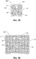
- FIG. 15 illustrates an exemplary embodiment of the modular attachment matrix array 100 attached or coupled to a carrier material 12.
- the modular attachment matrix array 100 comprises five substantially octagonally shaped matrix array apertures 120, arranged or grouped such that exemplary tunnel segments 135 are formed in a relatively horizontal, relatively vertical, and relatively diagonal manner.
- FIG. 16 illustrates an exemplary embodiment of the modular attachment matrix array 100 attached or coupled to a carrier material 12, wherein the modular attachment matrix array 100 comprises a plurality of substantially octagonally shaped matrix array apertures 120, as illustrated in FIG. 15 . However, as illustrated in FIG. 16 , the grouping of five matrix array apertures 120 is expanded to a plurality of arranged matrix array apertures 120.
- the total number of matrix array apertures 120 used to form the modular attachment matrix array 100 of the matrix array layer 110 is a design choice, based upon the desired area that the modular attachment matrix array 100 is to cover, whether attached to a carrier material 12 or as a standalone matrix array layer 110.
- FIG. 17 illustrates an exemplary embodiment of the modular attachment matrix array 100 attached or coupled to a carrier material 12, wherein the modular attachment matrix array 100 comprises four, spaced apart, substantially octagonally shaped matrix array apertures 120. As illustrated, the positioning of the matrix array apertures 120 still provides relatively horizontal, relatively vertical, and relatively diagonal tunnel segments 135. It should be appreciated that the arrangement or grouping of matrix array apertures 120, as illustrated in FIG. 17 , may be duplicated to create a matrix array layer 110 of any desired size and including any number of desired matrix array apertures 120, as illustrated, for example, in FIG. 18 .
- the arrangement or grouping of matrix array apertures 120 may be applied to the matrix array layer 110 in any desired arrangement.
- the matrix array apertures 120 are arranged in a repeating or semi-repeating series or sequence of equally spaced rows 113 and equally spaced columns 112, the length of each row 113 or column 112 may be varied to produce a desired arrangement of matrix array apertures 120.
- the arrangement or grouping of matrix array apertures 120 includes a number of partial matrix array apertures 120'.
- Each partial matrix array aperture 120' is formed of a partial or incomplete matrix array aperture. While the partial matrix array apertures 120' are each illustrated as being positioned at a beginning or end of a given row 113, it should be appreciated that partial matrix array apertures 120' may optionally be included at a beginning or an end of one or more rows 113, one or more columns 112, or within a given row 113 or column 112.
- FIGS. 20-22 illustrate various exemplary embodiments of an aperture array layer 110 and a modular attachment aperture array 100, according to the present disclosure.
- the modular attachment aperture array 100 includes an aperture array layer 110 having two or more array apertures 220 formed therethrough at spaced apart locations and arranged in one or more rows 113 and/or columns 112.
- the aperture array layer 110 is at least partially attached or coupled to a carrier material 12 and tunnel segments 135 are formed between adjacent array apertures 220.
- each of these elements corresponds to and operates similarly to the modular attachment aperture array 100, aperture array layer 110, array apertures 120, and tunnel segments 135, as described herein with reference to the modular attachment aperture array 100 of FIGS. 3-19 .
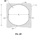
- FIGS. 20-22 illustrate an exemplary embodiment of an array aperture 220 that can be utilized in place of an array aperture 120 to form the modular attachment aperture array 100 and/or the aperture array layer 110.
- the array aperture 220 is formed of two substantially equal length, substantially parallel side portions or sides 223. It should be appreciated that the length or spacing, Sw, between of each of the side portions or sides 223 is a design choice based upon the desired functionality and/or appearance of the array aperture 220.
- An arcuate side 225 joins respective upper terminal ends of each of the side portions or sides 223, while an arcuate side 225 joins respective lower terminal ends of each of the sides 223.
- an upper arcuate side 225 joins respective upper terminal ends of each of the sides 223, while a lower arcuate side 225 joins respective lower terminal ends of each of the sides 223.
- the height or spacing, S H , between apexes of each of the sides 223 is equal to or substantially equal to the length or spacing, Sw, between of each of the sides 223.
- the height or spacing, S H , between apexes of each of the sides 223 is a design choice based upon the desired functionality and/or appearance of the array aperture 220.
- the angle of each arc forming each arcuate side 225 may be formed based upon the desired functionality and/or appearance of each array aperture 220.
- Each array aperture 220 is generally formed as an aperture or hole through the aperture array layer 110. It is possible for the aperture array layer 110 to operate as a stand-alone element, such as, for example, a sheet of aperture array layer 110 material, to which compatible accessories may be attached or coupled. However, in various exemplary embodiments, the aperture array layer 110 is at least partially attached or coupled to at least a portion of a carrier or carrier material, such as, for example, a carrier material 12. Thus, the aperture array layer 110 may be at least partially attached or coupled to an exemplary carrier, for example, an article of clothing, a vest, a plate carrier, a backpack, a pack, a bag, a platform, or another flexible, semi-rigid, or rigid carrier.
- an exemplary carrier for example, an article of clothing, a vest, a plate carrier, a backpack, a pack, a bag, a platform, or another flexible, semi-rigid, or rigid carrier.
- each array aperture 220 is also a design choice.
- the size of each array aperture 220 is influenced or dictated by the width of the accessory coupling element of a compatible accessory, such as, for example, the accessory coupling element 88 of a compatible accessory 81.
- the accessory coupling element 88 has a width of approximately 1 inch
- the length or spacing, Sw, between of each of the sides 223 and the height or spacing, S H between apexes of each of the sides 223 may optionally be approximately 1 inch, so as to allow the accessory coupling element 88 to be fitted within and interwoven between two or more array apertures 220.
- the length or spacing, Sw, between of each of the sides 223 and the height or spacing, S H , between apexes of each of the sides 223 may be such that only certain accessories are compatible with the aperture array layer 110 and the modular attachment aperture array 100.
- the array apertures 220 are arranged in a repeating or semi-repeating series or sequence of spaced apart, repeating patterns. In various exemplary embodiments, the array apertures 220 are arranged in a repeating or semi-repeating series or sequence of spaced apart rows 113 and columns 112. In various exemplary embodiments, the array apertures 220 are arranged in a series of equally spaced rows 113 and equally spaced columns 112.
- each of the rows 113 is spaced at a distance that is the same as the spacing between each of the columns 112. Alternatively, the spacing between each of the rows 113 is greater than or less than the spacing between each of the columns 112.
- the spacing between either edges or proximate centers of adjacent array apertures 220 is influenced or dictated by the width of the accessory webbing element 83 of a compatible accessory 81.
- the spacing between either edges or proximate centers of adjacent array apertures 220 may optionally be approximately 1 inch, so as to allow the accessory webbing element(s) 83 to be appropriately aligned between every other array aperture 220 in a vertical, horizontal, oblique, or diagonal direction.
- the spacing between either edges or proximate centers of adjacent array apertures 220 may be created such that only certain accessories are compatible with the aperture array layer 110 and the modular attachment aperture array 100.
- two or more adjacent array apertures 220 may comprise a row 113 and two or more adjacent array apertures 220 may comprise a column 112.
- the number of array apertures 220 formed in the aperture array layer 110 is a design choice based upon the desired size and/or functionality of the aperture array layer 110.
- each adjacent row 113 and/or column 112 of spaced apart array apertures 220 is offset such that either edges or proximate centers of adjacent array apertures 220 are offset by approximately ⁇ 45° or approximately ⁇ 90°. If for example, either edges or proximate centers of adjacent array apertures 220 are offset by ⁇ 45° or ⁇ 90°, an attached or coupled accessory 81 may be attached or coupled at least at ⁇ 0°, ⁇ 90°, or ⁇ 45°. Thus, it should be appreciated that the offset of adjacent rows 113 and/or columns 112 dictates the angle of oblique attachment of accessories.
- each array aperture 220 may be separated from each other array aperture 220 by a distance that is equal to or greater than a width of each array aperture 220.
- each array aperture 220 may be separated from each other array aperture 220 by a distance that is equal to or greater than a width of each array aperture 220.
- aperture array tunnel segments 135 are created between adjacent array apertures 220 (whether vertically, horizontally, obliquely, acutely, or diagonally adjacent).
- the aperture array layer 110 comprises a portion of aperture array layer 110 material that is at least partially attached or coupled to a carrier material 12 by aperture array layer attachment elements (not illustrated), such as stitching proximate a perimeter of the aperture array layer 110.
- the aperture array layer 110 may optionally be attached or coupled or further attached or coupled to the carrier material 12, via additional aperture array layer attachment elements (not illustrated).
- the aperture array layer attachment elements (not illustrated) may be spaced apart, as necessary or desirable, in order to further secure, attach, or couple the aperture array layer 110 to the carrier material 12.
- the number and placement of additional aperture array layer attachment elements is a design choice based upon the desired level of securement of the aperture array layer 110 to the carrier material 12 and/or to further ensure that the aperture array layer 110 will not separate or pull away from the carrier material 12, particularly if accessories are attached or coupled to the aperture array layer 110.
- the aperture array layer attachment elements comprise stitching.
- the aperture array layer 110 may be attached or coupled to the carrier material 12 at one or more aperture array layer attachment elements (not illustrated) via adhesive bonding, welding, screws, rivets, pins, mating hook and loop portions, snap or releasable fasteners, or other known or later developed means or methods for permanently or releasably attaching or coupling the aperture array layer 110 to the carrier material 12.
- the one or more aperture array layer attachment elements may be formed or positioned proximate a perimeter of the aperture array layer 110 or in one or more areas located within the one or more aperture array layers 110.
- the orientation of the aperture array layer 110, relative to the carrier material 12 is also a design choice.
- the aperture array layer 110 may optionally be attached or coupled to the carrier material 12, such that the rows 113 of array apertures 220 are substantially parallel to a longitudinal or other axis, along the length, of the exemplary carrier material 12, while the columns 112 of array apertures 220 are substantially perpendicular to the longitudinal or other axis of the carrier material 12. It should be appreciated that this is merely exemplary and the aperture array layer 110 may be attached at any desired angular or rotational orientation relative to the carrier material 12.
- the portions of material of the aperture array layer 110 between adjacent array apertures 220 form aperture array tunnel segments 135. If the aperture array layer 110 is attached to a carrier material 12, the aperture array tunnel segments 135 are formed between at least portions of the aperture array layer 110 and at least portions of the surface of the carrier material 12. The aperture array tunnel segments 135 provide areas for securing the accessory coupling element 88 of an accessory 81 to the aperture array layer 110. In this manner, an accessory coupling element 88 may be interwoven between the aligned aperture array tunnel segments 135 to removably attach the accessory 81 to the carrier material 12.
- the accessory 81 is aligned with the aperture array layer 110 in a desired orientation.
- the accessory 81 may optionally be aligned with the aperture array layer 110 in a generally vertical manner, in a generally horizontal manner, or in a generally oblique or diagonal manner. It should be understood that these orientations are relative to the orientation of the aperture array layer 110 and the orientation of the aperture array layer 110 relative to the carrier material 12.
- the exemplary accessory 81 may optionally include one or more substantially parallel, spaced apart accessory webbing elements 83. If more than one accessory webbing element 83 is included, the accessory webbing elements 83 are spaced apart so as to correspond to the spaces between the spaced apart array apertures 220.
- the accessory coupling element 88 may be interwoven between the aligned aperture array tunnel segments 135 and accessory tunnel segments 87 (alternating between adjacent array apertures 220 and/or alternate attachment apertures 121 of the aperture array layer 110 and accessory webbing elements 83 on the accessory 81 ) to removably attach the accessory 81 to the aperture array layer 110.
- an accessory 81 may be mounted to the aperture array layer 110 in a variety of orientations.
- a particular carrier material 12 includes an aperture array layer 110
- a variety of accessories may be interchangeably mounted to the aperture array layer 110 to accommodate a variety of desired configurations.
- FIGS. 23-37 illustrate certain elements and/or aspects of an exemplary embodiment of a modular attachment aperture array 300, according to the presently disclosed systems, methods, and/or apparatuses.
- the modular attachment aperture array 300 comprises at least some of an aperture array layer 310 having a plurality of spaced apart array apertures 320 formed therethrough, with tunnel segments 335 formed between certain of the spaced apart array apertures 320, as described herein.
- the modular attachment aperture array 300 may optionally be at least partially attached or coupled to at least a portion of a carrier or carrier material, such as, for example, a carrier material 12.
- each of these elements corresponds to and operates similarly to the modular attachment aperture array 100, aperture array layer 110, matrix array apertures 120, and tunnel segments 135, as described above with reference to the modular attachment aperture array 100 of FIGS. 3-19 .
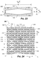
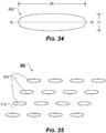
- FIGS. 23-37 illustrate an exemplary embodiment of the modular attachment aperture array 300, wherein each array aperture 320 is formed in the shape of an elongated octagon, truncated oval, or oval.
- the aperture array layer 310 is formed of a portion of a fabric-type or other material, such as, for example, chlorosulfonated polyethylene (CSPE) synthetic rubber (CSM).
- CSPE chlorosulfonated polyethylene
- the aperture array layer 310 is formed of a portion of Hypalon fabric or a nylon laminate.
- the present disclosure is not so limited.
- the aperture array layer 310 may be formed of a rigid material, a semi-rigid material, or a substantially flexible material.
- all or portions of the aperture array layer 310 may be made of any fabric or other material, such as, for example, woven fabrics, canvas, acrylics, sheet fabrics, films, nylon, spandex, vinyl, Polyvinyl Chloride (PVC), neoprene, or the like. Alternatively, all or portions of the aperture array layer 310 may be formed from multiple, similar or dissimilar materials. In various exemplary, non-limiting embodiments, the aperture array layer 310 may be water-resistant or may include a cushion material.
- the aperture array layer 310 may be formed of a substantially rigid material, such as plastic, having an appropriate, workable thickness.
- Alternate materials of construction of the aperture array layer 310 may include one or more of the following: steel, stainless steel, aluminum, titanium, polytetrafluoroethylene, and/or other metals, as well as various alloys and composites thereof, glass-hardened polymers, polymeric composites, polymer or fiber reinforced metals, carbon fiber or glass fiber composites, continuous fibers in combination with thermoset and thermoplastic resins, chopped glass or carbon fibers used for injection molding compounds, laminate glass or carbon fiber, epoxy laminates, woven glass fiber laminates, impregnate fibers, polyester resins, epoxy resins, phenolic resins, polyimide resins, cyanate resins, high-strength plastics, nylon, glass, or polymer fiber reinforced plastics, thermoform and/or thermoset materials, and/or various combinations of the foregoing.
- the terms fabric and material are to be given their broadest meanings and that the particular fabric(s) or material(s) used to form the aperture array layer 310 is a design choice based on the desired appearance and/or functionality of the modular attachment aperture array 300. In general, the material used to form the aperture array layer 310 is selected for its ability to allow a MOLLE-type accessory to be attached or coupled thereto.
- the modular attachment aperture array 300 of the present disclosure is operable with as few as two array apertures 320.
- the size and shape of the aperture array layer 310 is a design choice, based upon, for example, the size and shape of the carrier material 12 or portion of carrier material 12 that is desired to potentially accept attachment or coupling of accessories.
- the array apertures 320 are generally formed as apertures through the aperture array layer 310.
- Each array aperture 320 is defined by one or more continuous edges or edge portions.
- each array aperture 320 is formed in the shape of an elongated octagon.
- the edges or edge portions of each array aperture 320 is/are defined by a first height, H 1 , which extends so as to be defined between opposing edge portions 322 and 329.
- a second height, H 2 is defined by the lengths of opposing edge portions 325 and 326.
- the first height, H 1 is greater than the second height, H 2 .
- each array aperture 320 is/are further defined by a first width, W 1 , which extends so as to be defined between opposing edge portions 325 and 326.
- a second width, W 2 is defined by the lengths of the opposing edge portions 322 and 329.
- the first width, W 1 is greater than the second width, W 2 .
- Opposing edge portions 322 and 329 are substantially parallel to one another, while opposing edge portions 325 and 326 are substantially parallel to one another.
- Edge portion 323 extends between edge portions 325 and 322
- edge portion 324 extends between edge portions 326 and 322
- edge portion 327 extends between edge portions 325 and 329
- edge portion 328 extends between edge portions 326 and 329.
- the array aperture 320 takes the form of a substantially elongated octagon defined by edge portions 322, 323, 324, 325, 326, 327, 328, and 329.
- each of the array apertures 320 may generally be formed in the shape of an elongated octagon, wherein edge portions 322, 323, 324, 325, 326, 327, 328, and 329 join each other at rounded corners or edges (as illustrated in FIG. 25 ), an elongated octagon, wherein one or more edge portions 322, 323, 324, 325, 326, 327, 328, and 329 comprise a rounded or curved edge portions (as illustrated in FIG.
- each of the array apertures 320 is a design choice based upon the desired functionality and/or appearance of the modular attachment aperture array 300 and/or the aperture array layer 310.
- each array aperture 320 is also a design choice.
- the size of each array aperture 320 is influenced or dictated by the width of the accessory coupling element of a compatible accessory, such as, for example, the accessory coupling element 88 of a compatible accessory 81.
- the first width, W 1 of each array aperture 320 may optionally be approximately 1 inch, so as to allow the accessory coupling element 88 to be interwoven between two or more array apertures 320 and fitted within an aperture array tunnel segment 335 are created between array apertures 320.
- the size of each array aperture 320 may be created such that only certain accessories are compatible with the aperture array layer 310 and the modular attachment aperture array 300.
- the array apertures 320 are arranged in a repeating, alternating, staggered, or semi-repeating series or sequence of spaced apart, repeating patterns. In various exemplary embodiments, the array apertures 320 are arranged in a repeating, alternating, staggered, or semi-repeating series or sequence of spaced apart rows 313 and columns 312. In various exemplary embodiments, the array apertures 320 are arranged in a series of equally spaced rows 313 and alternatingly offset, equally spaced columns 312.
- the columns 312 are arranged such that each column 312 at least partially overlaps an adjacent column 312.
- the degree or amount of overlap of adjacent columns 312 is a design choice based upon the desired compatibility of certain accessories with the aperture array layer 310 and the modular attachment aperture array 300.
- the number and spacing of positioning possibilities of attached accessories can be increased.
- the incremental shift of accessory attachment possibilities can be decreased.
- overlapping columns 312 may, for example, allow attachment of accessories at approximately 1 ⁇ 2 inch, % inch, or 1 inch increments.
- the incremental attachment options are a design choice based upon the desired degree of overlap, if any, of the columns 312.
- the spacing between each of the rows 313 is less than or greater than the spacing between each of the columns 312.
- the spacing between either edge portions or proximate centers of adjacent array apertures 320 is influenced or dictated by the width of the accessory webbing element 83 of a compatible accessory 81.
- the spacing between either edges or proximate centers of adjacent array apertures 320 may optionally be approximately 1 inch, so as to allow the accessory webbing element(s) 83 to be appropriately aligned between every or every other array aperture 320 in a vertical, horizontal, oblique, or diagonal direction.
- the spacing between either edge portions or proximate centers of adjacent array apertures 320 may be created such that only certain accessories are compatible with the aperture array layer 310 and the modular attachment aperture array 300.
- two or more adjacent array apertures 320 may comprise a row 313 and two or more adjacent array apertures 320 may comprise a column 312, as illustrated, for example, in in FIG. 29 .
- the number of array apertures 320 formed in the aperture array layer 310 is a design choice based upon the desired size and/or functionality of the aperture array layer 310.
- each adjacent row 313 and/or column 312 of spaced apart array apertures 320 is offset such that either edges or proximate centers of adjacent array apertures 320 are offset by an angle, ⁇ , of approximately ⁇ 33° (as illustrated in FIG. 24 ).
- FIG. 28 illustrates an alternative spacing of the rows 313 and columns 312 forming the aperture array layer 310.
- each array aperture 320 is separated from each other array aperture 320 by a distance that is less than the first width, W 1 , of each array aperture 320.
- aperture array tunnel segments 335 are created between adjacent array apertures 320 (whether vertically, horizontally, obliquely, or diagonally adjacent).
- the aperture array layer 310 is formed as a stand-alone element, such as, for example, a sheet of aperture array layer 310 material, to which compatible accessories may be attached or coupled.
- the aperture array layer 310 may optionally be utilized as a portion of material used to form an accessory, such as, for example, a pouch or carrier.
- a portion of aperture array layer 310 may be utilized as a wall segment of a magazine or other pouch.
- several array apertures 320 may be formed in a portion of material, such that the portion of material constitutes a portion of aperture array layer 310.
- the aperture array layer 310 may optionally be at least partially attached or coupled to at least a portion of a carrier or carrier material, such as, for example, a carrier material 12.
- a carrier or carrier material such as, for example, a carrier material 12.
- the aperture array layer 310 may be at least partially attached or coupled to an exemplary carrier (such as, for example, exemplary carrier material 12 ), for example, an article of clothing, a vest, a plate carrier, a backpack, a pack, a bag, a platform, or another flexible, semi-rigid, or rigid carrier.
- the aperture array layer 310 is attached or coupled to a portion of carrier material 12, via stitching or other aperture array layer attachment elements (not illustrated).
- the aperture array layer attachment elements (not illustrated) may optionally be spaced apart, as necessary or desirable, in order to further secure, attach, or couple the aperture array layer 310 to the carrier material 12.
- the number and placement of aperture array layer attachment elements (not illustrated) is a design choice based upon the desired level of securement of the aperture array layer 310 to the carrier material 12 and/or to further ensure that the aperture array layer 310 will not separate or pull away from the carrier material 12, particularly if accessories are attached or coupled to the aperture array layer 310.
- the aperture array layer attachment elements comprise stitching.
- the aperture array layer 310 may be attached or coupled to the carrier material 12 at one or more aperture array layer attachment elements (not illustrated) via adhesive bonding, welding, screws, rivets, pins, mating hook and loop portions, snap or releasable fasteners, or other known or later developed means or methods for permanently or releasably attaching or coupling the aperture array layer 310 to the carrier material 12.
- the one or more aperture array layer attachment elements may be formed or positioned proximate a perimeter of the aperture array layer 310 or in one or more areas located within the one or more aperture array layers 310.
- the orientation of the aperture array layer 310, relative to the carrier material 12 is also a design choice.
- the array apertures 320 are illustrated as being arranged or oriented in a particular manner, relative to the aperture array layer 310, such that the rows 313 of array apertures 320 are arranged in an exemplary, horizontal fashion, while the columns 312 of array apertures 320 are arranged in an exemplary, vertical fashion. It should be appreciated that this is merely exemplary and the aperture array layer 310 may be formed, attach, or coupled at any desired angular or rotational orientation relative to a surface of the carrier material 12.
- the portions of material of the aperture array layer 310 between adjacent array apertures 320 form aperture array tunnel segments 335. If the aperture array layer 310 is attached to a carrier material 12, the aperture array tunnel segments 335 are formed between the aperture array layer 310 and the surface of the carrier material 12. The aperture array tunnel segments 335 provide areas for securing the accessory coupling element 88 of an accessory 81 to the aperture array layer 310. In this manner, an accessory coupling element 88 may be interwoven between the aligned aperture array tunnel segments 335 to removably attach the accessory 81 to the carrier material 12.
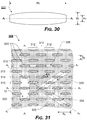
- FIGS. 30-37 illustrate an exemplary embodiment of an array aperture 320 and a modular attachment aperture array 300, according to the present disclosure.
- the modular attachment aperture array 300 includes an aperture array layer 310 having two or more array apertures 320 formed therethrough at spaced apart locations and arranged in one or more rows 313 and/or columns 312.
- the aperture array layer 310 is at least partially attached or coupled to a carrier material 12 and tunnel segments 335 are formed between adjacent array apertures 320.
- each of these elements corresponds to and operates similarly to the modular attachment aperture array 300, aperture array layer 310, array apertures 320, and tunnel segments 335, as described above with reference to the modular attachment aperture array 300 of FIGS. 34-29 .
- FIGS. 30-37 illustrate an exemplary embodiment of an array aperture 320 that can be utilized in place of an array aperture 120 to form the modular attachment aperture array 100 and/or the aperture array layer 310.
- the array aperture 320 includes a first height, H 1 , a second height, H 2 , and a first width, W 1 .
- Each array aperture 320 is formed of two substantially equal length, parallel sides 323, each having a height, H 2 . It should be appreciated that the width, W 1 , between of each of the sides 323 is a design choice based upon the desired functionality and/or appearance of the array aperture 320.
- An arcuate side 325 joins respective upper terminal ends and respective lower terminal ends of each of the sides 323.
- the height, H 1 is formed between apexes of each of the sides 323. It should be appreciated that the height, H 1 , between apexes of each of the sides 323 is a design choice based upon the desired functionality and/or appearance of the array aperture 320.
- the angle of each arc forming each arcuate side 325 may be formed based upon the desired functionality and/or appearance of each array aperture 320.
- Each array aperture 320 is generally formed as an aperture or hole through the aperture array layer 310. It is possible for the aperture array layer 310 to operate as a stand-alone element, such as, for example, a sheet of aperture array layer 310 material, to which compatible accessories may be attached or coupled. However, in various exemplary embodiments, the aperture array layer 310 is at least partially attached or coupled to at least a portion of a carrier or carrier material, such as, for example, a carrier material 12. Thus, the aperture array layer 310 may be at least partially attached or coupled to an exemplary carrier, for example, an article of clothing, a vest, a plate carrier, a backpack, a pack, a bag, a platform, or another flexible, semi-rigid, or rigid carrier.
- an exemplary carrier for example, an article of clothing, a vest, a plate carrier, a backpack, a pack, a bag, a platform, or another flexible, semi-rigid, or rigid carrier.
- each array aperture 320 is also a design choice.
- the size of each array aperture 320 is influenced or dictated by the width of the accessory coupling element of a compatible accessory, such as, for example, the accessory coupling element 88 of a compatible accessory 81.
- the width, W 1 between of each of the sides 323 may optionally be approximately 1 inch, so as to allow the accessory coupling element 88 to be fitted within and interwoven between two or more array apertures 320.
- the width, W 1 , between of each of the sides 323 may be such that only certain accessories are compatible with the aperture array layer 310 and the modular attachment aperture array 100.
- the array apertures 320 may be arranged in a repeating or semi-repeating series or sequence of spaced apart, repeating patterns.
- the array apertures 320 are arranged in a repeating or semi-repeating series or sequence of spaced apart rows 313 and columns 312.
- the array apertures 320 are arranged in a series of equally spaced rows 313 and equally spaced columns 312.
- each of the rows 313 is spaced at a distance that is the same as the spacing between each of the columns 312.
- the spacing between each of the rows 313 is greater than or less than the spacing between each of the columns 312.
- the spacing between either edges or proximate centers of adjacent array apertures 320 is influenced or dictated by the width of the accessory webbing element 83 of a compatible accessory 81.
- the spacing between either edges or proximate centers of adjacent array apertures 320 may optionally be approximately 1 inch, so as to allow the accessory webbing element(s) 83 to be appropriately aligned between every other array aperture 320 in a vertical, horizontal, oblique, or diagonal direction.
- the spacing between either edges or proximate centers of adjacent array apertures 320 may be created such that only certain accessories are compatible with the aperture array layer 310 and the modular attachment aperture array 100.
- two or more adjacent array apertures 320 may comprise a row 313 and two or more adjacent array apertures 320 may comprise a column 312.
- the number of array apertures 320 formed in the aperture array layer 310 is a design choice based upon the desired size and/or functionality of the aperture array layer 310.
- each adjacent row 313 and/or column 312 of spaced apart array apertures 320 is offset such that either edges or proximate centers of adjacent array apertures 320 are offset by approximately ⁇ 45°, approximately ⁇ 33°, or approximately ⁇ 90°. If for example, either edges or proximate centers of adjacent array apertures 320 are offset by ⁇ 45°, ⁇ 33°, or ⁇ 90°, an attached or coupled accessory 81 may be attached or coupled at least at ⁇ 0°, ⁇ 90°, ⁇ 33°, or ⁇ 45°.
- the offset of adjacent rows 313 and/or columns 312 dictates the angle of oblique attachment of accessories.
- each array aperture 320 may be separated from each other array aperture 320 by a distance that is equal to or greater than a width of each array aperture 320.
- each array aperture 320 may be separated from each other array aperture 320 by a distance that is equal to or greater than a width of each array aperture 320.
- aperture array tunnel segments 135 are created between adjacent array apertures 320 (whether vertically, horizontally, obliquely, acutely, or diagonally adjacent).
- the aperture array layer 310 comprises a portion of aperture array layer 310 material that is at least partially attached or coupled to a carrier material 12 by aperture array layer attachment elements (not illustrated), such as stitching proximate a perimeter of the aperture array layer 310.
- the aperture array layer 310 may optionally be attached or coupled or further attached or coupled to the carrier material 12, via additional aperture array layer attachment elements (not illustrated).
- the aperture array layer attachment elements (not illustrated) may be spaced apart, as necessary or desirable, in order to further secure, attach, or couple the aperture array layer 310 to the carrier material 12.
- the number and placement of additional aperture array layer attachment elements is a design choice based upon the desired level of securement of the aperture array layer 310 to the carrier material 12 and/or to further ensure that the aperture array layer 310 will not separate or pull away from the carrier material 12, particularly if accessories are attached or coupled to the aperture array layer 310.
- the aperture array layer attachment elements comprise stitching.
- the aperture array layer 310 may be attached or coupled to the carrier material 12 at one or more aperture array layer attachment elements (not illustrated) via adhesive bonding, welding, screws, rivets, pins, mating hook and loop portions, snap or releasable fasteners, or other known or later developed means or methods for permanently or releasably attaching or coupling the aperture array layer 310 to the carrier material 12.
- the one or more aperture array layer attachment elements may be formed or positioned proximate a perimeter of the aperture array layer 310 or in one or more areas located within the one or more aperture array layers 310.
- the orientation of the aperture array layer 310, relative to the carrier material 12 is also a design choice.
- the aperture array layer 310 may optionally be attached or coupled to the carrier material 12, such that the rows 313 of array apertures 320 are substantially parallel to a longitudinal or other axis, along the length, of the exemplary carrier material 12, while the columns 312 of array apertures 320 are substantially perpendicular to the longitudinal or other axis of the carrier material 12. It should be appreciated that this is merely exemplary and the aperture array layer 310 may be attached at any desired angular or rotational orientation relative to the carrier material 12.
- the portions of material of the aperture array layer 310 between adjacent array apertures 320 form aperture array tunnel segments 135. If the aperture array layer 310 is attached to a carrier material 12, the aperture array tunnel segments 135 are formed between at least portions of the aperture array layer 310 and at least portions of the surface of the carrier material 12. The aperture array tunnel segments 135 provide areas for securing the accessory coupling element 88 of an accessory 81 to the aperture array layer 310. In this manner, an accessory coupling element 88 may be interwoven between the aligned aperture array tunnel segments 135 to removably attach the accessory 81 to the carrier material 12.
- FIGS. 34-36 illustrate an exemplary embodiment of an array aperture 320 that can be utilized in place of an array aperture 120 to form the modular attachment aperture array 100 and/or the aperture array layer 310.
- the array aperture 320 includes a height, H 1 and a width, W 1 .
- Each array aperture 320 is formed of an oval shape having a height, H 1 and a width, W 1 .
- the height and width of each array aperture 320 is a design choice based upon the desired functionality and/or appearance of the array aperture 320.
- the height, H 1 is formed between vertical apexes of the array aperture 320 and the width, W 1 , is formed between horizontal apexes of the array aperture 320. It should be appreciated that the height, H 1 , between apexes of each of the sides 323 is a design choice based upon the desired functionality and/or appearance of the array aperture 320. Thus, the angle of each arc forming each arcuate side 325 may be formed based upon the desired functionality and/or appearance of each array aperture 320.
- the array apertures 320 may be arranged in a repeating or semi-repeating series or sequence of spaced apart, repeating patterns.
- array apertures 320 of varying designs may be arranged in a repeating or semi-repeating series or sequence of spaced apart, repeating patterns.
- the accessory 81 is aligned with the aperture array layer 310 in a desired orientation, similar to the fashion illustrated in FIGS. 5-12 .
- the accessory 81 may optionally be aligned with the aperture array layer 310 in a generally vertical or horizontal manner or a generally oblique or diagonal manner. It should be understood that these orientations are relative to the orientation of the aperture array layer 310 and the orientation of the aperture array layer 310 relative to any optional carrier material 12.
- the exemplary accessory 81 includes one or more substantially parallel, spaced apart accessory webbing elements 83. If more than one accessory webbing element 83 is included, the accessory webbing elements 83 are spaced apart so as to correspond to the spaces between the spaced apart array apertures 320.
- the accessory coupling element 88 may be interwoven between the aligned aperture array tunnel segments 335 and accessory tunnel segments 87 (alternating between adjacent array apertures 320 and/or alternate attachment apertures 321 of the aperture array layer 310 and accessory webbing elements 83 on the accessory 81 ) to removably attach the accessory 81 to the aperture array layer 310.
- an accessory 81 may be mounted to the aperture array layer 310 in a variety of orientations.
- a particular carrier material 12 includes an aperture array layer 310
- a variety of accessories may be interchangeably mounted to the aperture array layer 310 to accommodate a variety of desired configurations.
Landscapes
- Connections Arranged To Contact A Plurality Of Conductors (AREA)
- Details Of Connecting Devices For Male And Female Coupling (AREA)
- Toys (AREA)
Applications Claiming Priority (1)
| Application Number | Priority Date | Filing Date | Title |
|---|---|---|---|
| US201962818511P | 2019-03-14 | 2019-03-14 |
Publications (2)
| Publication Number | Publication Date |
|---|---|
| EP3708027A2 true EP3708027A2 (de) | 2020-09-16 |
| EP3708027A3 EP3708027A3 (de) | 2020-09-23 |
Family
ID=69844566
Family Applications (1)
| Application Number | Title | Priority Date | Filing Date |
|---|---|---|---|
| EP20163113.2A Withdrawn EP3708027A3 (de) | 2019-03-14 | 2020-03-13 | Modulares befestigungsöffnungsarray |
Country Status (1)
| Country | Link |
|---|---|
| EP (1) | EP3708027A3 (de) |
Cited By (1)
| Publication number | Priority date | Publication date | Assignee | Title |
|---|---|---|---|---|
| CN113413003A (zh) * | 2021-06-28 | 2021-09-21 | 昆明式怒蛙贸易有限责任公司 | 挂载结构、携具及制作方法 |
Family Cites Families (6)
| Publication number | Priority date | Publication date | Assignee | Title |
|---|---|---|---|---|
| DE8524342U1 (de) * | 1985-08-24 | 1986-02-27 | Knut Jaeger Marketing & Production Big Pack GmbH, 7311 Bissingen | Tragegestell für Rückenlasten, insbesondere für Rucksäcke |
| US7448115B2 (en) * | 2005-01-18 | 2008-11-11 | Illinois Tool Works Inc. | Modular attachment assembly |
| US8397966B2 (en) * | 2009-05-01 | 2013-03-19 | Douglas Shin Kim | System and methods for cordage storage/deployment and articles |
| US9144255B1 (en) * | 2012-02-02 | 2015-09-29 | Armorworks Enterprises LLC | System for attaching accessories to tactical gear |
| US9521897B2 (en) * | 2014-01-06 | 2016-12-20 | The Fechheimer Brothers Company | Customizable MOLLE adapter panel |
| US9664481B2 (en) * | 2014-08-07 | 2017-05-30 | 5.11, Inc. | Hexagonal attachment system |
-
2020
- 2020-03-13 EP EP20163113.2A patent/EP3708027A3/de not_active Withdrawn
Cited By (2)
| Publication number | Priority date | Publication date | Assignee | Title |
|---|---|---|---|---|
| CN113413003A (zh) * | 2021-06-28 | 2021-09-21 | 昆明式怒蛙贸易有限责任公司 | 挂载结构、携具及制作方法 |
| CN113413003B (zh) * | 2021-06-28 | 2024-01-23 | 昆明式怒蛙贸易有限责任公司 | 挂载结构、携具及制作方法 |
Also Published As
| Publication number | Publication date |
|---|---|
| EP3708027A3 (de) | 2020-09-23 |
Similar Documents
| Publication | Publication Date | Title |
|---|---|---|
| US11503899B2 (en) | Attachment aperture array matrix | |
| US11957236B2 (en) | Integral accessory attachment system | |
| US8608041B1 (en) | Multi-angle modular attachment system | |
| US9521897B2 (en) | Customizable MOLLE adapter panel | |
| US10070714B2 (en) | Hexagonal attachment system | |
| US11661254B1 (en) | Integral accessory attachment interface | |
| US7080430B2 (en) | Quick-mount interlocking attaching system | |
| US11517102B2 (en) | Attachment aperture array pattern | |
| US20130126566A1 (en) | Attachment System Substructure and Cummerbund of the Same | |
| US11388980B2 (en) | Modular attachment aperture array | |
| EP2201851B1 (de) | Tragausrüstung | |
| EP2476327A2 (de) | Kleidungsstück zum Tragen einer Last | |
| US20140263519A1 (en) | Backpack frame system with slotted frame | |
| US11864645B2 (en) | Interlocking attachment systems | |
| US12455143B2 (en) | Plate carrier | |
| US12213579B2 (en) | Bi-directional accessory attachment interface | |
| RU183065U1 (ru) | Крепление для сборки модульных единиц снаряжения | |
| HK1233464A1 (en) | Hexagonal attachment system | |
| HK1233464B (en) | Hexagonal attachment system |
Legal Events
| Date | Code | Title | Description |
|---|---|---|---|
| PUAI | Public reference made under article 153(3) epc to a published international application that has entered the european phase |
Free format text: ORIGINAL CODE: 0009012 |
|
| STAA | Information on the status of an ep patent application or granted ep patent |
Free format text: STATUS: THE APPLICATION HAS BEEN PUBLISHED |
|
| PUAL | Search report despatched |
Free format text: ORIGINAL CODE: 0009013 |
|
| AK | Designated contracting states |
Kind code of ref document: A2 Designated state(s): AL AT BE BG CH CY CZ DE DK EE ES FI FR GB GR HR HU IE IS IT LI LT LU LV MC MK MT NL NO PL PT RO RS SE SI SK SM TR |
|
| AX | Request for extension of the european patent |
Extension state: BA ME |
|
| AK | Designated contracting states |
Kind code of ref document: A3 Designated state(s): AL AT BE BG CH CY CZ DE DK EE ES FI FR GB GR HR HU IE IS IT LI LT LU LV MC MK MT NL NO PL PT RO RS SE SI SK SM TR |
|
| AX | Request for extension of the european patent |
Extension state: BA ME |
|
| RIC1 | Information provided on ipc code assigned before grant |
Ipc: A45F 3/06 20060101ALI20200819BHEP Ipc: A45C 13/00 20060101AFI20200819BHEP Ipc: A45C 13/02 20060101ALN20200819BHEP Ipc: A45C 3/08 20060101ALN20200819BHEP |
|
| STAA | Information on the status of an ep patent application or granted ep patent |
Free format text: STATUS: REQUEST FOR EXAMINATION WAS MADE |
|
| 17P | Request for examination filed |
Effective date: 20210323 |
|
| RBV | Designated contracting states (corrected) |
Designated state(s): AL AT BE BG CH CY CZ DE DK EE ES FI FR GB GR HR HU IE IS IT LI LT LU LV MC MK MT NL NO PL PT RO RS SE SI SK SM TR |
|
| GRAP | Despatch of communication of intention to grant a patent |
Free format text: ORIGINAL CODE: EPIDOSNIGR1 |
|
| STAA | Information on the status of an ep patent application or granted ep patent |
Free format text: STATUS: GRANT OF PATENT IS INTENDED |
|
| INTG | Intention to grant announced |
Effective date: 20230526 |
|
| STAA | Information on the status of an ep patent application or granted ep patent |
Free format text: STATUS: THE APPLICATION IS DEEMED TO BE WITHDRAWN |
|
| 18D | Application deemed to be withdrawn |
Effective date: 20231006 |