EP3707846B1 - Verfahren zur präambelpunktierung - Google Patents
Verfahren zur präambelpunktierung Download PDFInfo
- Publication number
- EP3707846B1 EP3707846B1 EP18801249.6A EP18801249A EP3707846B1 EP 3707846 B1 EP3707846 B1 EP 3707846B1 EP 18801249 A EP18801249 A EP 18801249A EP 3707846 B1 EP3707846 B1 EP 3707846B1
- Authority
- EP
- European Patent Office
- Prior art keywords
- preamble
- puncture pattern
- management frames
- preamble puncture
- processor
- Prior art date
- Legal status (The legal status is an assumption and is not a legal conclusion. Google has not performed a legal analysis and makes no representation as to the accuracy of the status listed.)
- Active
Links
Images


Classifications
-
- H—ELECTRICITY
- H04—ELECTRIC COMMUNICATION TECHNIQUE
- H04L—TRANSMISSION OF DIGITAL INFORMATION, e.g. TELEGRAPHIC COMMUNICATION
- H04L5/00—Arrangements affording multiple use of the transmission path
- H04L5/0001—Arrangements for dividing the transmission path
- H04L5/0003—Two-dimensional division
- H04L5/0005—Time-frequency
- H04L5/0007—Time-frequency the frequencies being orthogonal, e.g. OFDM(A) or DMT
-
- H—ELECTRICITY
- H04—ELECTRIC COMMUNICATION TECHNIQUE
- H04W—WIRELESS COMMUNICATION NETWORKS
- H04W28/00—Network traffic management; Network resource management
- H04W28/02—Traffic management, e.g. flow control or congestion control
- H04W28/06—Optimizing the usage of the radio link, e.g. header compression, information sizing, discarding information
- H04W28/065—Optimizing the usage of the radio link, e.g. header compression, information sizing, discarding information using assembly or disassembly of packets
-
- H—ELECTRICITY
- H04—ELECTRIC COMMUNICATION TECHNIQUE
- H04L—TRANSMISSION OF DIGITAL INFORMATION, e.g. TELEGRAPHIC COMMUNICATION
- H04L5/00—Arrangements affording multiple use of the transmission path
- H04L5/003—Arrangements for allocating sub-channels of the transmission path
- H04L5/0053—Allocation of signalling, i.e. of overhead other than pilot signals
-
- H—ELECTRICITY
- H04—ELECTRIC COMMUNICATION TECHNIQUE
- H04W—WIRELESS COMMUNICATION NETWORKS
- H04W84/00—Network topologies
- H04W84/02—Hierarchically pre-organised networks, e.g. paging networks, cellular networks, WLAN [Wireless Local Area Network] or WLL [Wireless Local Loop]
- H04W84/10—Small scale networks; Flat hierarchical networks
- H04W84/12—WLAN [Wireless Local Area Networks]
Definitions
- WLANs wireless local area networks
- AP wireless access point
- STAs wireless stations
- a set of STAs can communicate with each other through a common AP in what is referred to as a basic service set (BSS).
- BSS basic service set
- the present disclosure describes techniques for preamble puncturing, and in particular, techniques that support preamble puncturing for single user (SU) transmission. As described herein, these techniques may be implemented as methods, apparatuses, computer-readable media, and means for wireless communications.
- WLANs wireless local area networks
- 6 GHz band may allow for unlicensed operation of WLAN.
- finding contiguous 80 MHz or 160 MHz idle channels for operation may be difficult.
- Incumbent technologies which may also be referred to as bandwidth exclusion zones, may be associated with certain frequency bands used by already present, existing, or established wireless technologies that WLAN communications need to avoid interfering with or with which interference is to be minimized. That is, when using wide bands it may be difficult to avoid overlapping with existing technologies. Preamble puncturing may be introduced to avoid interference with the incumbent technologies.
- an access point (AP) transmitting to several clients using 160 MHz transmission may have to puncture the preamble and the data for part of those clients.
- the channels that are not available within the 160 MHz will not be carrying any preamble or data (e.g., no orthogonal frequency-division multiplexing (OFDM) symbols).
- OFDM orthogonal frequency-division multiplexing
- IEEE 802.11ax introduces a preamble puncturing mode which allows non-primary 20 MHz channels to be zeroed out in ⁇ 80 MHz bandwidth transmissions. This approach is currently only specified for downlink (DL) multi-user (MU) Physical Layer Convergence Procedure (PLCP) Protocol Data Units (PPDUs) and not for SU transmissions. Uplink (UL) preamble puncturing is generally possible using high-efficiency (HE) trigger-based (TB) PPDUs. In a current version of IEEE 802.1 1ax, each wireless station (STA) is allowed to be assigned to only one (1) resource unit (RU) (both UL and DL) so preamble puncturing may not be applied to SU transmission. This disclosure provides various techniques to expand preamble puncturing to SU transmissions in 6 GHz. These techniques, however, are also applicable to other frequency bands such as 2.4 GHz band or 5 GHz band.
- FIGs. 1-22 Various aspects are now described in more detail with reference to the FIGs. 1-22 .
- numerous specific details are set forth in order to provide a thorough understanding of one or more aspects. It may be evident, however, that such aspect(s) may be practiced without these specific details.
- the term "component” as used herein may be one of the parts that make up a system, may be hardware, firmware, and/or software stored on a computer-readable medium, and may be divided into other components.
- EHT extremely high throughput
- FIG. 1 is a conceptual diagram 100 illustrating an example of a WLAN deployment in connection with various techniques described herein, including the various aspects described herein in connection with preamble puncturing.
- the WLAN may include one or more APs and one or more STAs associated with a respective AP.
- One or more of the APs and one or more of the STAs may support the techniques described herein.
- API 105-a in basic service set 1 (BSS1) and AP2 105-b in BSS2, which may be referred to as an overlapping BSS (OBSS).
- API 105-a is shown as having at least three associated STAs (STA1 115-a, STA2 115-b, STA3 115-c) and coverage area 110-a, while AP2 105-b is shown having one associated STA4 115-c and coverage area 110-b.
- STAs and AP associated with a particular BSS may be referred to as members of that BSS.
- the coverage area 110-a of API 105-a may overlap part of the coverage area 110-b of AP2 105-b such that a STA may be within the overlapping portion of the coverage areas 110-a and 110-b.
- the number of BSSs, APs, and STAs, and the coverage areas of the APs described in connection with the WLAN deployment of FIG. 1 are provided by way of illustration and not of limitation.
- An STA 115 in FIG. 1 can include a modem (not shown) with a preamble puncturing component 2250 as described in more detail below in FIG. 22 .
- the modem of the STA 115 may support preamble puncturing operations described in this disclosure.
- an AP 105 in FIG. 1 can include a modem (not shown) with a preamble puncturing component 1850 as described in more detail below in FIG. 18 .
- the modem of the AP 105 may support the preamble puncturing operations described in this disclosure.
- the APs (e.g., API 105-a and AP2 105-b) shown in FIG. 1 are generally fixed terminals that provide backhaul services to STAs 115 within its coverage area or region. In some applications, however, the AP 105 may be a mobile or non-fixed terminal.
- the STAs (e.g., STA1 115-a, STA2 115-b, STA3 115-c, STA4 115-d) shown in FIG. 1 , which may be fixed, non-fixed, or mobile terminals, utilize the backhaul services of their respective AP to connect to a network, such as the Internet.
- Examples of an STA 115 include, but are not limited to: a cellular phone, a smart phone, a laptop computer, a desktop computer, a personal digital assistant (PDA), a personal communication system (PCS) device, a personal information manager (PIM), a personal navigation device (PND), a global positioning system, a multimedia device, a video device, an audio device, a device for the Internet-of-Things (IoT), or any other suitable wireless apparatus requiring the backhaul services of an AP 105.
- PDA personal digital assistant
- PCS personal communication system
- PIM personal information manager
- PND personal navigation device
- a global positioning system a multimedia device, a video device, an audio device, a device for the Internet-of-Things (IoT), or any other suitable wireless apparatus requiring the backhaul services of an AP 105.
- An STA 115 may also be referred to by those skilled in the art as: a subscriber station, a mobile unit, a subscriber unit, a wireless unit, a remote unit, a mobile device, a wireless device, a wireless communications device, a remote device, a mobile subscriber station, an access terminal, a mobile terminal, a wireless station, a remote terminal, a handset, a user agent, a mobile client, a client, user equipment (UE), or some other suitable terminology.
- An AP 105 may also be referred to as: a base station, a base transceiver station, a radio base station, a radio transceiver, a transceiver function, or any other suitable terminology.
- an STA 115 that supports HE BSS operations may be referred to as an HE STA.
- an AP 105 that supports HE BSS operations may be referred to as an HE AP.
- an HE STA may operate as an HE AP or as an HE mesh STA, for example.
- Each of STA1 115-a, STA2 115-b, STA3 115-c, STA4 115-d may be implemented with a protocol stack.
- the protocol stack can include a physical layer for transmitting and receiving data in accordance with the physical and electrical specifications of the wireless channel, a data link layer for managing access to the wireless channel, a network layer for managing source to destination data transfer, a transport layer for managing transparent transfer of data between end users, and any other layers necessary or desirable for establishing or supporting a connection to a network.
- Each of API 105-a and AP2 105-b can include software applications and/or circuitry to enable associated STAs to connect to a network via communications link 125.
- the APs can send frames or packets to their respective STAs 115 and receive frames or packets from their respective STAs 115 to communicate data and/or control information (e.g., signaling).
- Each of API 105-a and AP2 105-b can establish a communications link 125 with an STA 115 that is within the coverage area of the corresponding AP 105.
- Communications link 125 can comprise communications channels that can enable both UL and DL communications.
- an STA 115 can first authenticate itself with the AP 105 and then associate itself with the AP 105. Once associated, communications link 125 may be established between AP 105 and STA 115 such that AP 105 and the associated STA 115 may exchange frames or messages through a direct communications channel.
- the wireless communication system may not have a central AP (e.g., AP 105), but rather may function as a peer-to-peer network between the STAs 115. Accordingly, the functions of AP 105 described herein may alternatively be performed by one or more of STAs 115.
- Such systems may be referred to as an "ad-hoc" communication systems in which terminals asynchronously communication directly with each other without use of any specific AP referred to as an independent BSS (IBSS) or mesh.
- IBSS independent BSS
- one or more APs may transmit on one or more channels (e.g., multiple narrowband channels, each channel including a frequency bandwidth) a beacon signal (or simply a "beacon"), via communications link 125 to STA(s) 115 of the wireless communication system, which may help STA(s) 115 to synchronize their timing with APs 105, or which may provide other information or functionality.
- a beacon signal or simply a "beacon”
- Such beacons may be transmitted periodically. In one aspect, the period between successive beacon transmissions may be referred to as a beacon interval. Transmission of a beacon may be divided into a number of groups or intervals.
- the beacon may include, but is not limited to, such information as timestamp information to set a common clock, a peer-to-peer network identifier, a device identifier, capability information, a beacon interval, transmission direction information, reception direction information, a neighbor list, and/or an extended neighbor list, some of which are described in additional detail below.
- a beacon may include information that is both common (e.g., shared) amongst several devices and specific to a given device.
- such beacons or other management frames may be used to provide signaling for preamble puncturing as described below.
- FIG. 2 shows a diagram 200 illustrating an example of an HE MU PPDU format as part of an overview of preamble puncturing supported by IEEE 802.11ax.
- preamble puncturing is only specified for DL and MU PPDU transmissions, and not for SU transmission.
- the pre-HE preamble e.g., fields L-STF, L-LTF, L-SIG, RL-SIG, HE-SIG-A, and HE-SIG-B in the diagram 200
- the data portion is transmitted in OFDMA and avoids RU allocation in the 20MHz channel with interference.
- UL preamble puncturing can be done using HE trigger-based PPDU.
- An AP may avoid the allocation of any clients in a busy 20 MHz channel.
- An STA e.g., STA 115
- STA 115 may only transmit pre-HE preamble in the 20 MHz channels that overlap with its assigned RU.
- each STA is allowed to be assigned to only one RU (both UL and DL) and therefore preamble puncturing is not supported for SU transmissions.
- the present disclosure provides two approaches to enable preamble puncturing in SU transmissions.
- One approach involves using a MU PPDU format for SU preamble puncture.
- Another approach involves using a SU PPDU format for SU preamble puncture.
- HE-SIG-A field can indicate 4 preamble puncturing modes (described in more detail with respect to FIGs. 3A and 3B ).
- the HE-SIG-B field can indicate punctured RUs and assign all remaining RUs to the same STA.
- the HE-SIG-B field is the field that carries information about multiuser transmission.
- the HE-SIG-B field is not present in other formats, for example, SU PPDU format may not carry the HE-SIG-B field.
- UL can also use the HE MU PPDU for SU preamble puncture transmission.
- an AP identifier (ID) is sent instead of an STA ID.
- the approach that involves using HE MU PPDU format for SU preamble puncture may have the benefits that it requires fewer modifications to existing IEEE specifications and may be backward compatible. On the other hand, this approach may require a higher preamble overhead and may only support a subset of all possible puncture modes due to the limitations in [1 2 1 2] structure of the HE-SIG-B field.
- the [1 2 1 2] structure means that channels 1 and 3 will carry the same HE-SIG-B information or content, and channels 2 and 4 will carry the same HE-SIG-B information or content for reliability purposes.
- the HE MU PPDU format in FIG. 2 may provide two points of information. One point being that pre-HE modulated preamble is transmitted per 20 MHz. That is, until HE-SIG-B, all blocks are transmitted per 20 MHz. Another point being that it is also possible to puncture in more refine ways (see e.g., HE-STF, HE-LTFs, HE data).
- FIG. 3A shows a diagram 300 illustrating examples of a first preamble puncturing mode for 80 MHz transmissions and a second preamble puncturing mode for 80 MHz transmissions.
- a secondary 20 MHz (S20) channel is punctured and in the second preamble puncturing mode a secondary 40 MHz left (S40-L) channel or a secondary 40 MHz right (S40-R) channel is punctured.
- S40-L secondary 40 MHz left
- S40-R secondary 40 MHz right
- FIG. 3B shows a diagram 310 illustrating examples of a third preamble puncturing mode for 160 MHz transmissions and a fourth preamble puncturing mode for 160 MHz transmissions.
- a secondary 20 MHz (S20) channel is punctured and in the fourth preamble puncturing mode a secondary 40 MHz left (S40-L) channel, a secondary 40 MHz right (S40-R) channel, or both are punctured.
- S40-L secondary 40 MHz left
- S40-R secondary 40 MHz right
- the preamble puncturing modes shown in FIGs. 3A and 3B are but a limited number of all possible puncturing modes that can be used for preamble puncturing for SU transmissions.
- Another approach may involve the use of management frames to signal different preamble puncturing modes or puncture patterns. This approach is different from indicating a puncture pattern in a per-packet basis. This approach may have more flexibility than the one described above that involves the use of HE MU PPDU format because it may support a wider range of puncturing modes or puncture patterns.
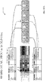
- FIG. 4 shows a diagram 400 illustrating an example of puncture regions (or bandwidth exclusion zones) that are needed in a 320 MHz channel width at 6 GHz due to incumbent technologies for 160 MHz channel width IEEE 802.11ax transmissions at 6 GHz.
- the regions (e.g., frequency bands) occupied by incumbent technologies need to be punctured to avoid interfering with the existing technologies.
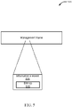
- one approach to indicate the puncturing regions is to signal a puncture pattern using management frames (see e.g., management frame 500 in FIG. 5 ).
- a puncture pattern (which indicates the regions of incumbent technologies) is signaled by an AP in the BSS by transmitting puncture pattern information through management frames.
- management frames can be beacons, association response frames, management action frames, and the like.
- the preamble puncture pattern is semi-static, that is, it does not vary on a per-packet basis.
- a semi-static puncture pattern is acceptable since in 6 GHz the incumbent technologies may occupy a portion of the bandwidth for longer periods of time.
- the AP can signal the new puncture pattern through management frames in the BSS. It is possible that a range from about 5.9 GHz to about 7.1 GHz may be made into an unlicensed spectrum, in which case any incumbent technologies in that range will need to be protected from interference from WLAN.
- An AP 105 may announce through management frames the operating bandwidth of the BSS 110 (e.g., 160 MHz).
- the primary 20 MHz (e.g., P20 channel) channel is also advertised within the BSS 110.
- Per-packet bandwidth may also be indicated in the preamble (e.g., HE-SIG-A) of the packet. It can be less than or equal to the 160 MHz operating bandwidth of the BSS 110.
- the P20 channel may not be punctured since the P20 channel is the anchor channel on which all control information is exchanged.
- the AP 105 can relocate the P20 channel if the P20 channel falls in an exclusion zone.
- the AP 105 may also announce through management frames the preamble puncture pattern.
- the puncture pattern can be indicated as a bitmap of 7 bits, indicating the puncture status of each of the 7 non-primary 20 MHz channels in 160 MHz (note that the primary 20 MHz channel is not punctured so it need not be included in the bitmap).
- the puncture pattern granularity can be finer (e.g., 10 MHz), in which case one way of signaling is through a 14 bit bitmap. Finer granularity of puncture pattern provides flexibility in puncturing bandwidth efficiency.
- FIG. 5 shows the management frame 500, which may be a beacon, an association response frame, or a management action frame, for example.
- the management frame 500 may include a field or information element (IE) 505 in which the bitmap described above providing the puncture pattern information can be included.
- IE information element
- management frames e.g., management frame 500
- Other aspects associated with the approach of using management frames include the behavior of a transmitter and a receiver in the signaling operation and the implication of clear channel assessment rules.
- the transmitter may use HE SU PPDU or HE MU PPDU format for transmission. That is, in contrast to the other approaches described above that involves only HE MU PPDU format, the PPDU format need not be a limitation in the implementation in this approach.
- the preamble of PPDUs is unchanged from what is currently supported in the IEEE 802.11ax specification. That is, the bandwidth field in the HE-SIG-A field is set as if no puncturing is being done. The transmitter zeros out the punctured sub-carriers based on puncturing knowledge provided by management frames periodically.
- a component (e.g., modem 2214 and/or preamble puncturing component 2250) of the receiver (e.g., STA 115) may use the preamble of the PPDU received and the puncturing information from management frames to demodulate the received packet.
- CCA Clear Channel Assessment
- the 20 MHz subchannels that belong to the exclusion zone are zeroed out in the preamble puncture transmission.
- An operating example of the technique or approach described above includes having an AP (e.g., AP 105) start its BSS and advertise or broadcast the preamble puncture pattern in management frames (e.g., beacons, management action frames, association response frames).
- the AP 105 e.g., the transmitter
- the AP 105 knows about the preamble puncture pattern and hence zeros out the punctured channels (e.g., no preamble and data is modulated on the punctured sub-carriers).
- a component (e.g., modem 2214 and/or preamble puncturing component 2250) of the STA or receiver decodes the incoming packet taking into account the preamble puncture pattern, of which it is aware because of the management frames.
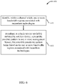
- FIG. 6 is a flow diagram illustrating an example of a method 600 in accordance with aspects of the present disclosure. Aspects of the method 600 may be performed by one or more components of the AP 105 shown in FIG. 18 , including but not limited to processors 1812, a modem 1814, a transceiver 1802, a memory 1816, a radio frequency (RF) front end 1888, a preamble puncturing component 1850, a management frames puncture pattern signaling component 1860, and/or a preamble overhead reduction component 1870.
- processors 1812 a modem 1814
- a transceiver 1802 a memory 1816
- RF radio frequency
- the management frames puncture pattern signaling component 1860 may include one or more subcomponents such as a bandwidth region identifying component 1862 and/or a preamble puncture pattern broadcast component 1864 that are configured to perform specific functions, actions, or processes associated with the method 600.
- the method 600 includes identifying, within a channel width, one or more bandwidth regions associated with incumbent technologies or bandwidth exclusion zones.
- one or more components e.g., bandwidth region identifying component 1862
- the AP 105 may identify, within a channel width, one or more bandwidth regions associated with incumbent technologies or bandwidth exclusion zones.
- the AP 105 may identify the one or more bandwidth regions based on frequency bands used by already present, existing, or established wireless technologies that WLAN communications need to avoid interfering with or with which interference is to be minimized.
- the method 600 includes broadcasting, to a BSS initiated by the access point, a preamble puncture pattern in one or more management frames, the preamble puncture pattern being based on the one or more bandwidth regions associated with incumbent technologies.
- a preamble puncture pattern broadcast component 1864 may broadcast, to a BSS, a preamble puncture pattern in a management frame.
- the method 600 further includes setting, for a packet to be transmitted, a bandwidth in an HE-SIG-A field of a preamble of the packet.
- the method 600 further includes zeroing out one or more channels for transmission of the packet based on the preamble puncture pattern.
- the one or more management frames include a beacon, an association response frame, or a management action frame.
- the one or more management frames include a bitmap indicating the preamble puncture pattern.
- the bitmap may be included in an information element.
- the method 600 further includes transmitting a packet based on the preamble puncture pattern, the packet possibly having an HE SU PPDU format or an HE MU PPDU format.
- the one or more management frames indicate an operating bandwidth of the BSS.
- the method 600 further includes identifying a change in the one or more bandwidth regions associated with incumbent technologies; and broadcasting, to the BSS initiated by the access point, a different preamble puncture pattern in one or more additional management frames, the different preamble puncture pattern being based on the change in the one or more bandwidth regions associated with incumbent technologies.
- the AP 105 may identify a change in the one or more bandwidth regions associated with incumbent technologies based on a change in the preamble puncture pattern from semi-static puncture pattern.
- the broadcasting of the one or more management frames includes periodically broadcasting the one or more management frames.
- the method 600 further includes DL SU preamble puncturing for a particular client of the access point based at least in part on the advertising of the preamble puncture pattern in the one or more management frames, wherein the particular client of the access point has allocated more than one resource unit.
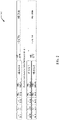
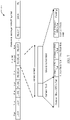
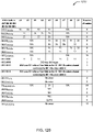
- FIG. 7 illustrates a diagram 700 providing details of an HE-SIG-B field in the HE MU PPDU format as currently implemented in IEEE 802.1 1ax.
- the HE-SIG-B field is separately encoded on each 20 MHz band.
- the encoding structure in one such 20 MHz band is shown in FIG. 7 .
- the HE-SIG-A in the HE MU PPDU format indicates the bandwidth mode.
- the HE-SIG-B includes a common field and a user specific field.
- the common field includes information regarding resource unit allocation (RU allocation subfield/RU table) such as the RU assignment in frequency domain, the RUs allocated for MU-MIMO and the number of users in MU-MIMO.
- a diagram 1100 in FIG. 11 illustrates an example of a common field format.
- Diagrams 1200, 1210, and 1220 in FIGs. 12A-12C provide an example of an RU allocation subfield.
- the user specific field includes zero or more user blocks followed by padding (if present). Each user block includes at most two user fields.
- a diagram 1300 in FIG. 13 illustrates an example of a user field format for a non-MU MIMO allocation.
- the HE-SIG-B has two content channels and adheres to [1 2 1 2] structure in which the content channels alternate as illustrated in diagrams 1400, 1410, 1420, and 1430 in FIGs. 14A-14D , respectively.
- HE-SIG-A field can indicate 4 preamble puncturing modes (described in more detail with respect to FIGs. 3A and 3B ).
- the HE-SIG-B field can indicate punctured RUs and assign all remaining RUs to the same STA.
- UL can also use the HE MU PPDU for SU preamble puncture transmission.
- an AP identifier (ID) is sent instead of an STA ID.
- the approach that involves using a HE MU PPDU format for SU preamble puncture may have the benefits that the HE MU PPDU format for SU preamble puncture requires fewer modifications to the existing IEEE specifications and may be backward compatible. On the other hand, this approach may require a higher preamble overhead and may only support a subset of all possible puncture modes due to the limitations in [1 2 1 2] structure of the HE-SIG-B field.
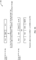
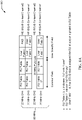
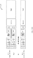
- FIGs. 8A and 8B show diagrams 800 and 810 illustrating examples of puncturing in 80 MHz and 160 MHz transmissions as it is currently supported in IEEE 802.11ax.
- User fields 1, 3, and 4 contain the same information because of identical modulation coding scheme (MCS), coding, number of streams (NSTS) used in all RUs assigned to the same STA.
- MCS modulation coding scheme
- NSTS number of streams
- RU tables 1, 3, and 4 indicates "242 with 1 user”
- RU table 2 indicates "242 RU Empty" with no user field for it.
- User fields 1 - 4 have STA ID that is assigned by the RU allocation signaled in the RU table.
- RU tables 1, 3, 4, 5, 6, and 7 indicate "242 with 1 user” and RU table 2 indicates "242 RU Empty" with no user field for it.
- the user fields 1 - 8 have STA ID that is assigned by the RU allocation signaled in the RU table.
- a single user field per content channel may be sufficient in case of SU preamble puncture using HE MU PPDU format as is described below.
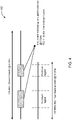
- FIG. 9 shows a diagram 900 that illustrates an overhead reduction technique for SU preamble puncturing in accordance with aspects of the present disclosure.
- the common field may indicate not only the RU size but may also indicate the SU puncture mode, that is, the RU assigned to the same single user. With such an approach, a single user field may be needed, thus reducing the overall size of the user specific field of the HE-SIG-B field.
- New entries may need to be defined in the RU allocation subfield (see e.g., FIGs. 12A-12C ) to indicate the SU puncture mode. Examples of these entries may include, but need not be limited to: 242 SU puncture mode, 484 SU puncture mode, 996 SU puncture mode, L106 empty, R106 SU puncture mode, and L106 SU puncture mode with R106 empty.
- changes to the common field to support SU preamble puncturing may include the following aspects.
- a 'same single user' is assigned to the various 242 RUs and is indicated in the common field. That is, the common field may signal in an RU allocation subfield that each of 242 RU (20 MHz) is assigned to the same single user in the ⁇ 80MHz SU preamble puncture transmission using HE MU PPDU format. This is in contrast to the current approach where ownership of RU is determined through user field and not common field.
- the RU allocation subfield may be used to signal that lower frequency 106 RU in 242 RU (8 MHz in 20 MHz) is punctured while the Higher frequency 106 RU in 242 RU is assigned to the same single user.
- the RU allocation subfield may be used to signal that higher frequency 106 RU in 242 RU is punctured while the lower frequency 106 RU in 242RU is assigned to the same single user. Similar rules may be defined for 52 RU in 242 RU (4 MHz in 20 MHz). Reserved values present in the RU Allocation subfield can be used to indicate the above values or signaling.
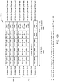
- FIGs. 10A and 10B show diagrams 1000 and 1010 illustrating examples of overhead reduction when puncturing in 80 MHz and 160 MHz transmissions based on the approach described above for changing the information provided in the common field of the HE-SIG-B field.
- RU tables 1 - 4 indicate "242 assigned to the same single user" and user field 1 has STA ID that is assigned by the RU allocation signaled in the RU tables 1 - 4.
- the overhead for the user field is reduced for 80 MHz SU punctured transmission by 50% compared to current IEEE 802.11ax configurations.
- the overhead for the user field is reduced for 160 MHz SU punctured transmission by 75% compared to current IEEE 802.11ax configurations.
- an HE MU PPDU may be used for indicating SU preamble puncture, where the HE MU PPDU includes a common information field and per user information fields.
- This approach can work without having to make substantial changes by reusing existing framework of MU puncturing.
- this approach can result in the introduction of some overhead.
- An MU PPDU is used for SU preamble puncture indication instead of using an SU PPDU because current specifications (e.g., IEEE 802.11ax) only allow puncturing when using a MU tone plan.
- an MU PPDU is naturally used for SU preamble puncture indication because an MU PPDU comes with the MU tone plan.
- an SU preamble puncture indication is performed using an MU PPDU.
- the HE-SIG-A field of the HE MU PPDU is used to indicate pre-defined puncture patterns.
- the HE-SIG-B of the HE MU PPDU can be used to further refine the puncture pattern.
- the common field indicates RU sizes and allocation to a number of users, while the per user field identifies each user that is assigned an RU.
- the per user field provides info on MCS, NSTS, coding, etc.
- the existing framework for MU puncturing is maintained or reused but provides an optimization of the overhead.
- the HE MU PPDU is used for SU preamble puncture transmissions.
- overhead of the HE-SIG-B signaling may be reduced by the following features: (1) the HE-SIG-A field is used to indicate that an incoming transmission is an SU preamble punctured transmission; (2) the puncture pattern is indicated in a management frame rather than in the HE-SIG-A field and the HE-SIG-B field; (3) the common field is absent or not present in such transmissions; and (4) only one per user field is present in each content channel.
- FIG. 15A is a diagram 1500 illustrating a current HE MU PPDU structure.
- an example is shown in which an 80 MHz HE MU PPDU is being transmitted, which is required to have 4 common information fields corresponding to each of the 20 MHz channels, as well as multiple per user fields.
- This example shows that using the HE MU PPDU for SU preamble puncture indication can incur a significant overhead.
- FIG. 15B is a diagram 1510 illustrating another technique for SU preamble puncture transmission with HE MU PPDU in which the 20_1 20 MHz channel is punctured, the common field is absent or not present, and only a single per user field is present in each content channel.
- the HE MU PPDU has a reduced or optimized overhead when compared to the HE MU PPDU shown in FIG. 15A .
- the HE-SIG-A field can be used to indicate incoming transmission is SU Preamble punctured transmission.
- SIGB compression subfield e.g., bit
- the HE-SIG-A of the HE MU PPDU is set to "1"
- the common field is absent and only per user fields are present.
- the bandwidth subfield values 0-3 for 20/40/80/160 MHz are applicable, while values 4-7 that indicate punctures are not applicable.
- the SIGB compression subfield may be set to a predetermined number (e.g., "1") and the bandwidth value may be set to a predetermined value (e.g., 4 or 5).
- setting the SIGB compression subfield to the predetermined number (e.g., "1") and the bandwidth value a first predetermined value (e.g., 4) may indicate SU Preamble puncture 80 MHz PPDU.
- setting the SIGB compression subfield to the predetermined number (e.g., "1") and the bandwidth value a second predetermined value (e.g., 5) may indicate SU Preamble puncture 160/80+80 MHz PPDU.
- some of the bandwidth values can be reserved.
- a new rule may be defined in which only one per user field is used for each content channel.
- the content of the per user field can be identical (e.g., same MCS, coding, DCM).
- the puncture pattern information can be distributed in a management frame.
- This additional approach for SU preamble puncture indication using HE MU PPDU not only reuses existing framework of MU puncturing but also allows for the reduction of signaling overhead.
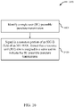
- FIG. 16 is a flow diagram illustrating an example of a method 1600 in accordance with aspects of the present disclosure. Aspects of the method 1600 may be performed by one or more components shown in the AP 105 of FIG. 18 , including but not limited to the processors 1812, the modem 1814, the transceiver 1802, the memory 1816, the RF front end 1888, the preamble puncturing component 1850, the management frames puncture pattern signaling component 1860, and/or a preamble overhead reduction component 1870.
- the preamble overhead reduction component 1870 may include one or more subcomponents, such as identifying component 1872 and/or signaling component 1874, that are configured to perform specific functions, actions, or processes associated with the method 1600.
- the method 1600 includes identifying a single user (SU) preamble puncture transmission.
- a single user (SU) preamble puncture transmission For example, one or more of the components (e.g., identifying component 1872) of the AP 105 may identify an SU preamble puncture transmission based on an RU allocation subfield indicating an SU puncture mode.
- the method 1600 includes signaling in a common portion of a SIG-B field of a MU PPDU format that an RU size is assigned to a same user to indicate the SU preamble puncture transmission.
- one or more of the components (signaling component 1874) of the AP 105 may signal in a common portion of a SIG-B field of an MU PPDU (e.g., a HE-SIG-B field of an HE MU PPDU or a EHT-SIG-B field of an EHT MU PPDU) that an RU size is assigned to a same user to indicate the SU preamble puncture transmission.
- a SIG-B field of an MU PPDU e.g., a HE-SIG-B field of an HE MU PPDU or a EHT-SIG-B field of an EHT MU PPDU
- a user specific portion of the SIG-B field includes only a single user field for each channel.
- the signaling in the common portion of a SIG-B field that the RU size is assigned to the same user is signaled by a value of an RU allocation subfield.
- having the signaling in the common portion of a SIG-B field that the RU size assigned to the same user includes signaling in an RU allocation subfield that a lower frequency 106 RU (8 MHz) in a 242 RU (20 MHz) is punctured while a higher frequency 106 RU in the 242 RU is assigned to the same user.
- having the signaling in the common portion of a SIG-B field that the RU size assigned to the same user includes signaling in an RU allocation subfield that a higher frequency 106 RU in a 242 RU is punctured while a lower frequency 106 RU in the 242 RU is assigned to the same user.
- having the signaling in the common portion of a SIG-B field that the RU size assigned to the same user includes signaling in an RU allocation subfield that a lower frequency 52 RU (4 MHz) in a 242 RU (20 MHz) is punctured while a higher frequency 52 RU in the 242 RU is assigned to the same user.
- having the signaling in the common portion of an HE-SIG-B field that the RU size assigned to the same user includes signaling in an RU allocation subfield that a higher frequency 52 RU in a 242 RU is punctured while a lower frequency 52 RU in the 242 RU is assigned to the same user.
- the SU preamble puncture transmission includes puncturing of a secondary 20 MHz (S20) channel in an 80 MHz transmission.
- S20 secondary 20 MHz
- the SU preamble puncture transmission includes puncturing of a secondary 20 MHz (S20) channel in a 160 MHz transmission.
- S20 secondary 20 MHz
- FIG. 17 is a flow diagram illustrating an example of a method 1700 in accordance with aspects of the present disclosure. Aspects of the method 1700 may be performed by one or more components of the AP 105 shown in FIG. 18 , including but not limited to the processors 1812, the modem 1814, the transceiver 1802, the memory 1816, the RF front end 1888, the preamble puncturing component 1850, the management frames puncture pattern signaling component 1860, and/or a preamble overhead reduction component 1870.
- the method 1700 includes indicating a puncture pattern via one or more management frames.
- the components e.g., identifying component 1872
- the AP 105 may indicate a puncture pattern via one or more management frames.
- the method 1700 includes indicating via a preamble of an MU PPDU that an incoming transmission is an SU preamble puncture transmission based on the puncture pattern.
- the components (signaling component 1874) of the AP 105 may indicate, via a preamble of an MU PPDU, that an incoming transmission is an SU preamble puncture transmission based on the puncture pattern.
- the MU PPDU does not contain a common field.
- the method 1700 may include indicating via the preamble of the MU PPDU that an incoming transmission is an SU preamble puncture transmission includes providing an indication in a SIG-A field.
- the method 1700 may include indicating via the preamble of the MU PPDU that an incoming transmission is an SU preamble puncture transmission includes setting a SIGB compression bit and a bandwidth subfield value to indicate SU preamble puncture 80 MHZ PPDU or to indicate SU preamble puncture 160/80+80 MHz PPDU.
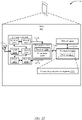
- FIG. 18 describes hardware components and subcomponents of a wireless communications device (e.g., AP 105) for implementing the techniques for preamble puncturing provided by this disclosure.
- a wireless communications device e.g., AP 105
- the AP 105 may include a variety of components, including components such as one or more processors 1812, the memory 1816, the transceiver 1802, and the modem 1814 in communication via one or more buses 1644, which may operate in conjunction with the preamble puncturing component 1850 to enable one or more of the functions described herein as well as one or more methods (e.g., methods 600 and 1600) of the present disclosure.
- the one or more processors 1812, the memory 1816, the transceiver 1802, and/or the modem 1814 may be communicatively coupled via the one or more buses 1644. Further, the one or more processors 1812, the modem 1814, the memory 1816, the transceiver 1802, as well the RF front end 1888, may be configured to support preamble puncturing operations.
- the preamble puncturing component 1850 may support one or both of the approaches described above. When the preamble puncturing component 1850 supports the approach that involves the use of management frames, the preamble puncturing component 1850 may include and/or enable the management frames puncture pattern signaling component 1860.
- the preamble puncturing component 1850 may include and/or enable the preamble overhead reduction component 1870.
- the preamble puncturing component 1850 may include and/or enable both the management frames puncture pattern signaling component 1860 and the preamble overhead reduction component 1870.
- the management frames puncture pattern signaling component 1860 is configured to perform various functions, actions, operations, and/or processes associated with the use of management frames from the perspective of an AP.
- the preamble overhead reduction component 1870 is configured to perform various functions, actions, operations, and/or processes associated with signaling additional information in the common field of the HE-SIG-B field to reduce the overhead in the user specific field.
- the management frames puncture pattern signaling component 1860 and/or the preamble overhead reduction component 1870 can be configured to perform the additional approach described above for SU preamble puncture indication using HE MU PPDU with puncture indication in management frame.
- the one or more processors 1816 may include the modem 1814 that may use one or more modem processors.
- the various functions related to the preamble puncturing component 1850 may be included in the modem 1814 and/or the one or more processors 1812 and, in an aspect, can be executed by a single processor, while in other aspects, different ones of the functions may be executed by a combination of two or more different processors.
- the one or more processors 1812 may include any one or any combination of a modem processor, or a baseband processor, or a digital signal processor, or a transmit processor, or a receiver processor, or a transceiver processor associated with the transceiver 1802. In other aspects, some of the features of the one or more processors 1812 and/or the modem 1814 associated with the preamble puncturing component 1850 may be performed by the transceiver 1802.
- the memory 1816 may be configured to store data used herein and/or local versions of applications or the preamble puncturing component 1850 and/or one or more of its subcomponents being executed by at least one processor 1812.
- the memory 1816 can include any type of computer-readable medium usable by a computer or at least one processor 1812, such as random access memory (RAM), read only memory (ROM), tapes, magnetic discs, optical discs, volatile memory, non-volatile memory, and any combination thereof.
- the memory 1816 may be a non-transitory computer-readable storage medium that stores one or more computer-executable codes defining the preamble puncturing component 1850 and/or one or more of its subcomponents, and/or data associated therewith, when the AP 105 is operating at least one processor 1812 to execute the preamble puncturing component 1850 and/or one or more of its subcomponents.
- the transceiver 1802 may include at least one receiver 1806 and at least one transmitter 1808.
- the receiver 1806 may include hardware, firmware, and/or software code executable by a processor for receiving data, the code comprising instructions and being stored in a memory (e.g., computer-readable medium).
- the receiver 1806 may be, for example, an RF receiver.
- the receiver 1806 may receive signals transmitted by at least one wireless communications device (e.g., STA 115). Additionally, the receiver 1806 may process such received signals, and also may obtain measurements of the signals, such as, but not limited to, energy per chip to interference power ratio (Ec/Io), signal-to-noise ratio (SNR), reference signal received power (RSRP), received signal strength indicator (RSSI), etc.
- Ec/Io energy per chip to interference power ratio
- SNR signal-to-noise ratio
- RSRP reference signal received power
- RSSI received signal strength indicator
- the transmitter 1808 may include hardware, firmware, and/or software code executable by a processor for transmitting data, the code comprising instructions and being stored in a memory (e.g., computer-readable medium).
- a suitable example of the transmitter 1808 may include, but is not limited to, an RF transmitter.
- the wireless communications device or AP 105 may include the RF front end 1888 mentioned above, which may operate in communication with the one or more antennas 1865 and the transceiver 1802 for receiving and transmitting radio transmissions.
- the RF front end 1888 may be connected to the one or more antennas 1865 and can include one or more low-noise amplifiers (LNAs) 1890, one or more switches 1892, one or more power amplifiers (PAs) 1898, and one or more filters 1896 for transmitting and receiving RF signals.
- LNAs low-noise amplifiers
- PAs power amplifiers
- the LNA 1890 can amplify a received signal at a desired output level.
- each LNA 1890 may have a specified minimum and maximum gain values.
- the RF front end 1888 may use the one or more switches 1892 to select a particular LNA 1890 and its specified gain value based on a desired gain value for a particular application.
- the one or more PA(s) 1898 may be used by the RF front end 1888 to amplify a signal for an RF output at a desired output power level.
- each PA 1898 may have specified minimum and maximum gain values.
- the RF front end 1888 may use the one or more switches 1892 to select a particular PA 1898 and its specified gain value based on a desired gain value for a particular application.
- the one or more filters 1896 may be used by the RF front end 1888 to filter a received signal to obtain an input RF signal.
- a respective filter 1896 can be used to filter an output from a respective PA 1898 to produce an output signal for transmission.
- each filter 1896 can be connected to a specific LNA 1890 and/or PA 1898.
- the RF front end 1888 can use one or more switches 1892 to select a transmit or receive path using a specified filter 1896, LNA 1890, and/or PA 1898, based on a configuration as specified by the transceiver 1802 and/or the one or more processors 1812.
- the transceiver 1802 may be configured to transmit and receive wireless signals through the one or more antennas 1865 via the RF front end 1888.
- the transceiver 1802 may be tuned to operate at specified frequencies.
- the modem 1814 can configure the transceiver 1802 to operate at a specified frequency and power level based on the configuration of the wireless communications device or AP 105 and the communication protocol used by the modem 1814.
- the modem 1814 can be a multiband-multimode modem, which can process digital data and communicate with the transceiver 1802 such that the digital data is sent and received using the transceiver 1802.
- the modem 1814 can be multiband and be configured to support multiple frequency bands for a specific communications protocol.
- the modem 1814 can be multimode and be configured to support multiple operating networks and communications protocols.
- the modem 1814 can control one or more components of wireless communications device or AP 105 (e.g., the RF front end 1888, the transceiver 1802) to enable transmission and/or reception of signals based on a specified modem configuration.
- the modem configuration may be based on the mode of the modem and the frequency band in use.
- the modem configuration may be based on AP configuration information associated with wireless communications device or AP 105.
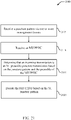
- FIGs. 19-21 are flow diagrams illustrating examples of methods 1900, 2000, and 2100 in accordance with aspects of the present disclosure. Aspects of the methods 1900, 2000, and 2100 may be performed by one or more components of the STA 115 shown in FIG. 22 , including but not limited to processors 2212, a modem 2214, a transceiver 2202, a memory 2216, an RF front end 2288, and/or a preamble puncturing component 2250.
- the method 1900 includes receiving a preamble puncture pattern in one or more management frames, the preamble puncture pattern being based on one or more bandwidth regions associated with incumbent technologies within a channel width, wherein the preamble puncture pattern is broadcasted to the BSS in the one or more management frames.
- the components e.g., processors 2212, modem 2214, and/or preamble puncturing component 2250
- the STA 115 may receive a preamble puncture pattern in one or more management frames, where the preamble puncture pattern is based on one or more bandwidth regions associated with incumbent technologies.
- the method 1900 includes receiving a packet.
- the components e.g., processors 2212, modem 2214, and/or preamble puncturing component 2250
- the STA 115 may receive a packet from the AP 105.
- the packet may contain the preamble puncture pattern, as described above.
- the method 1900 includes decoding the packet based on the preamble puncture pattern.
- the components e.g., processors 2212, modem 2214, and/or preamble puncturing component 2250
- the STA 115 may decode the packet based on the preamble puncture pattern, as previously described.
- the method 2000 includes receiving a packet including a common portion of a SIG-B field of an MU PPDU format that an RU size is assigned to a same user to indicate an SU preamble puncture transmission.
- the components e.g., processors 2212, modem 2214, and/or preamble puncturing component 2250
- the STA 115 may receive a packet including a common portion of a SIG-B field of an MU PPDU format that an RU size is assigned to a same user to indicate an SU preamble puncture transmission.
- the method 2000 includes decoding the packet based on the SU preamble puncture transmission.
- the components e.g., processors 2212, modem 2214, and/or preamble puncturing component 2250
- the STA 115 may decode the packet based on the SU preamble puncture transmission.
- the method 2100 includes receiving a puncture pattern via one or more management frames.
- the components e.g., processors 2212, modem 2214, and/or preamble puncturing component 2250
- the STA 115 may receiving a puncture pattern via one or more management frames.
- the method may also include receiving an MU PPDU.
- the components e.g., processors 2212, modem 2214, and/or preamble puncturing component 2250
- the STA 115 may receive an MU PPDU.
- the method 2100 includes determining that an incoming transmission is an SU preamble puncture transmission based on the puncture pattern and the preamble of the MU PPDU.
- the components e.g., processors 2212, modem 2214, and/or preamble puncturing component 2250
- the STA 115 may determine that an incoming transmission is an SU preamble puncture transmission based on the puncture pattern and the preamble of the MU PPDU.
- the method 2100 includes decoding the MU PPDU based on the SU puncture pattern.
- the components e.g., processors 2212, modem 2214, and/or preamble puncturing component 2250
- the STA 115 may decode the MU PPDU based on the SU puncture pattern.
- FIG. 22 describes hardware components and subcomponents of a wireless communications device (e.g., STA 115) for implementing the techniques for preamble puncturing provided by this disclosure.
- a wireless communications device e.g., STA 115
- the STA 115 may include a variety of components, including one or more processors 2212, a memory 2216, a modem 2214, and a transceiver 2202, which may communicate between them using a bus 2244.
- the one or more processors 2212, the memory 2216, the transceiver 2202, and/or the modem 2214 may be communicatively coupled via the one or more buses 2244.
- the transceiver 2202 may include a receiver 2206 and a transmitter 2208.
- the STA 115 may include an RF front end 2288 and one or more antennas 1765, where the RF front end 2288 may include LNA(s) 2290, switches 2292, filters 2296, and PA(s) 2298. Each of these components or subcomponents of the STA 115 may operate in a similar manner as the corresponding components described above in connection with FIG. 18 .
- the one or more processors 2212, the memory 2216, the transceiver 2202, and the modem 2214 may operate in conjunction with the preamble puncturing component 2250 to enable one or more of the functions described herein in connection with an STA (e.g., receiver) for preamble puncturing.
- STA e.g., receiver
- Information and signals may be represented using any of a variety of different technologies and techniques.
- data, instructions, commands, information, signals, bits, symbols, and chips that may be referenced throughout the above description may be represented by voltages, currents, electromagnetic waves, magnetic fields or particles, optical fields or particles, computer-executable code or instructions stored on a computer-readable medium, or any combination thereof.
- a specially-programmed device such as but not limited to a processor, a digital signal processor (DSP), an ASIC, a FPGA or other programmable logic device, a discrete gate or transistor logic, a discrete hardware component, or any combination thereof designed to perform the functions described herein.
- DSP digital signal processor
- a specially-programmed processor may be a microprocessor, but in the alternative, the processor may be any conventional processor, controller, microcontroller, or state machine.
- a specially-programmed processor may also be implemented as a combination of computing devices, e.g., a combination of a DSP and a microprocessor, multiple microprocessors, one or more microprocessors in conjunction with a DSP core, or any other such configuration.
- the functions described herein may be implemented in hardware, software executed by a processor, firmware, or any combination thereof. If implemented in software executed by a processor, the functions may be stored on or transmitted over as one or more instructions or code on a non-transitory computer-readable medium. Other examples and implementations are within the scope of the appended claims. For example, due to the nature of software, functions described above can be implemented using software executed by a specially programmed processor, hardware, firmware, hardwiring, or combinations of any of these. Features implementing functions may also be physically located at various positions, including being distributed such that portions of functions are implemented at different physical locations.
- Computer-readable media includes both computer storage media and communication media including any medium that facilitates transfer of a computer program from one place to another.
- a storage medium may be any available medium that can be accessed by a general purpose or special purpose computer.
- computer-readable media can comprise RAM, ROM, EEPROM, CD-ROM or other optical disk storage, magnetic disk storage or other magnetic storage devices, or any other medium that can be used to carry or store desired program code means in the form of instructions or data structures and that can be accessed by a general-purpose or special-purpose computer, or a general-purpose or special-purpose processor.
- any connection is properly termed a computer-readable medium.
- Disk and disc include compact disc (CD), laser disc, optical disc, digital versatile disc (DVD), floppy disk and Blu-ray disc where disks usually reproduce data magnetically, while discs reproduce data optically with lasers. Combinations of the above are also included within the scope of computer-readable media.
Landscapes
- Engineering & Computer Science (AREA)
- Signal Processing (AREA)
- Computer Networks & Wireless Communication (AREA)
- Mobile Radio Communication Systems (AREA)
- Synchronisation In Digital Transmission Systems (AREA)
Claims (15)
- Verfahren zur drahtlosen Kommunikation in drahtlosen lokalen Netzwerken, WLANs, wobei das Verfahren von einer drahtlosen Vorrichtung durchgeführt wird, umfassend:Identifizieren (605), innerhalb einer Kanalbreite, einer oder mehrerer Bandbreitenregionen, die mit etablierten Technologien assoziiert sind;Rundsenden (610), an einen Basisdienstsatz, BSS, der von der drahtlosen Vorrichtung initiiert wird, eines Präambelpunktionsmusters in einem oder mehreren Verwaltungsrahmen, wobei das Präambelpunktionsmuster auf der einen oder den mehreren Bandbreitenregionen basiert, die mit etablierten Technologien assoziiert sind; undÜbertragen eines Pakets basierend auf dem Präambelpunktionsmuster.
- Vorrichtung zur drahtlosen Kommunikation in drahtlosen lokalen Netzwerken, WLANs, umfassend:einen Sendeempfänger;einen Speicher, der konfiguriert ist, um Anweisungen zu speichern; undeinen Prozessor, der kommunikativ mit dem Speicher gekoppelt ist, wobei der Prozessor konfiguriert ist, um die Anweisungen auszuführen zum:Identifizieren (605), innerhalb einer Kanalbreite, einer oder mehrerer Bandbreitenregionen, die mit etablierten Technologien assoziiert sind;Rundsenden (610), an einen Basisdienstsatz, BSS, der von der Vorrichtung initiiert wird, eines Präambelpunktionsmusters in einem oder mehreren Verwaltungsrahmen, wobei das Präambelpunktionsmuster auf der einen oder den mehreren Bandbreitenregionen basiert, die mit etablierten Technologien assoziiert sind; undÜbertragen eines Pakets basierend auf dem Präambelpunktionsmuster.
- Vorrichtung nach Anspruch 2, wobei der Prozessor ferner konfiguriert ist, um die Anweisungen auszuführen zum:
Einstellen, für ein zu übertragendes Paket, einer Bandbreite in einem SIG-A-Feld einer Präambel des Pakets. - Vorrichtung nach Anspruch 3, wobei der Prozessor ferner konfiguriert ist, um die Anweisungen auszuführen zum:
Ausnullen eines oder mehrerer Kanäle zur Übertragung des Pakets basierend auf dem Präambelpunktionsmuster. - Vorrichtung nach Anspruch 2, wobei der eine oder die mehreren Verwaltungsrahmen einen Beacon, einen Assoziationsantwortrahmen oder einen Verwaltungsaktionsrahmen beinhalten.
- Vorrichtung nach Anspruch 2, wobei der eine oder die mehreren Verwaltungsrahmen eine Bitmap beinhalten, die das Präambelpunktionsmuster anzeigt.
- Vorrichtung nach Anspruch 6, wobei die Bitmap in einem Informationselement enthalten ist.
- Vorrichtung nach Anspruch 2, wobei der Prozessor ferner konfiguriert ist, um die Anweisungen auszuführen zum:
Übertragen eines Pakets basierend auf dem Präambelpunktionsmuster, wobei das Paket ein Einzelbenutzer-, SU-, Physical Layer Convergence Procedure Protocol Data Unit-, PPDU-, Format oder ein Mehrbenutzer-, MU-, PPDU-Format hat. - Vorrichtung nach Anspruch 2, wobei der eine oder die mehreren Verwaltungsrahmen eine Betriebsbandbreite des BSS anzeigen.
- Vorrichtung nach Anspruch 2, wobei der Prozessor ferner konfiguriert ist, um die Anweisungen auszuführen zum:Identifizieren einer Änderung in der einen oder den mehreren Bandbreitenregionen, die mit etablierten Technologien assoziiert sind; undRundsenden, an den BSS, der von der Vorrichtung initiiert wird, eines unterschiedlichen Präambelpunktionsmusters in einem oder mehreren zusätzlichen Verwaltungsrahmen, wobei das unterschiedliche Präambelpunktionsmuster auf der Änderung in der einen oder den mehreren Bandbreitenregionen basiert, die mit etablierten Technologien assoziiert sind.
- Vorrichtung nach Anspruch 2, wobei der Prozessor ferner konfiguriert ist, um die Anweisungen auszuführen zum:
periodischen Rundsenden des einen oder der mehreren Verwaltungsrahmen. - Vorrichtung nach Anspruch 2, wobei der Prozessor ferner konfiguriert ist, um die Anweisungen auszuführen zum:
Ermöglichen einer Downlink-Einzelbenutzer-, SU-, Präambelpunktion für einen bestimmten Client der Vorrichtung basierend zumindest teilweise auf der Ankündigung des Präambelpunktionsmusters in dem einen oder den mehreren Verwaltungsrahmen, wobei der bestimmte Client der Vorrichtung mehr als eine Ressourceneinheit zugewiesen hat. - Verfahren zur drahtlosen Kommunikation in drahtlosen lokalen Netzwerken, WLANs, wobei das Verfahren von einer drahtlosen Vorrichtung in einem Basisdienstsatz, BSS, durchgeführt wird, umfassend:Empfangen (1905) eines Präambelpunktionsmusters in einem oder mehreren Verwaltungsrahmen, wobei das Präambelpunktionsmuster auf einer oder mehreren Bandbreitenregionen basiert, die mit etablierten Technologien innerhalb einer Kanalbreite assoziiert sind, wobei das Präambelpunktionsmuster an den BSS in den einen oder mehreren Verwaltungsrahmen rundgesendet wird;Empfangen (1910) eines Pakets; undDecodieren (1915) des Pakets basierend auf dem Präambelpunktionsmuster.
- Vorrichtung zur drahtlosen Kommunikation in drahtlosen lokalen Netzwerken, WLANs, wobei die Vorrichtung in einem Basisdienstsatz, BSS, ist, umfassend:einen Sendeempfänger;einen Speicher, der konfiguriert ist, um Anweisungen zu speichern; undeinen Prozessor, der kommunikativ mit dem Speicher gekoppelt ist, wobei der Prozessor konfiguriert ist, um die Anweisungen auszuführen zum:
Empfangen (1905) eines Präambelpunktionsmusters in einem oder mehreren Verwaltungsrahmen, wobei das Präambelpunktionsmuster auf einer oder mehreren Bandbreitenregionen basiert, die mit etablierten Technologien innerhalb einer Kanalbreite assoziiert sind, wobei dasPräambelpunktionsmuster an den BSS in den einen oder mehreren Verwaltungsrahmen rundgesendet wird;Empfangen (1910) eines Pakets; undDecodieren (1915) des Pakets basierend auf dem Präambelpunktionsmuster. - Computerprogramm, umfassend Anweisungen, die, wenn das Programm von einem Computer ausgeführt wird, den Computer veranlassen, das Verfahren nach Anspruch 1 oder 13 auszuführen.
Priority Applications (1)
| Application Number | Priority Date | Filing Date | Title |
|---|---|---|---|
| EP22197623.6A EP4135252B1 (de) | 2017-11-06 | 2018-10-30 | Techniken zur präambelpunktierung |
Applications Claiming Priority (4)
| Application Number | Priority Date | Filing Date | Title |
|---|---|---|---|
| US201762582115P | 2017-11-06 | 2017-11-06 | |
| US201862659997P | 2018-04-19 | 2018-04-19 | |
| US16/173,481 US10827385B2 (en) | 2017-11-06 | 2018-10-29 | Techniques for preamble puncturing |
| PCT/US2018/058216 WO2019089598A2 (en) | 2017-11-06 | 2018-10-30 | Techniques for preamble puncturing |
Related Child Applications (2)
| Application Number | Title | Priority Date | Filing Date |
|---|---|---|---|
| EP22197623.6A Division EP4135252B1 (de) | 2017-11-06 | 2018-10-30 | Techniken zur präambelpunktierung |
| EP22197623.6A Division-Into EP4135252B1 (de) | 2017-11-06 | 2018-10-30 | Techniken zur präambelpunktierung |
Publications (2)
| Publication Number | Publication Date |
|---|---|
| EP3707846A2 EP3707846A2 (de) | 2020-09-16 |
| EP3707846B1 true EP3707846B1 (de) | 2022-11-16 |
Family
ID=66329119
Family Applications (2)
| Application Number | Title | Priority Date | Filing Date |
|---|---|---|---|
| EP22197623.6A Active EP4135252B1 (de) | 2017-11-06 | 2018-10-30 | Techniken zur präambelpunktierung |
| EP18801249.6A Active EP3707846B1 (de) | 2017-11-06 | 2018-10-30 | Verfahren zur präambelpunktierung |
Family Applications Before (1)
| Application Number | Title | Priority Date | Filing Date |
|---|---|---|---|
| EP22197623.6A Active EP4135252B1 (de) | 2017-11-06 | 2018-10-30 | Techniken zur präambelpunktierung |
Country Status (6)
| Country | Link |
|---|---|
| US (1) | US10827385B2 (de) |
| EP (2) | EP4135252B1 (de) |
| CN (1) | CN111295858B (de) |
| SG (1) | SG11202002871TA (de) |
| TW (1) | TWI778162B (de) |
| WO (1) | WO2019089598A2 (de) |
Families Citing this family (53)
| Publication number | Priority date | Publication date | Assignee | Title |
|---|---|---|---|---|
| US11405924B2 (en) * | 2017-12-08 | 2022-08-02 | Mediatek Singapore Pte. Ltd. | Communication interference mitigation systems and methods |
| US11452098B2 (en) | 2018-04-20 | 2022-09-20 | Qualcomm Incorporated | Dual band channel bonding and puncturing |
| US11483838B2 (en) | 2018-06-13 | 2022-10-25 | Intel Corporation | Increased utilization of wireless frequency channels partially occupied by incumbent systems |
| US12588044B2 (en) * | 2018-07-27 | 2026-03-24 | Mediatek Singapore Pte. Ltd. | Transmission protection mechanism in 6 GHz |
| WO2020080813A1 (ko) * | 2018-10-17 | 2020-04-23 | 엘지전자 주식회사 | 무선랜 시스템에서 데이터를 송신하는 방법 및 장치 |
| US10721040B2 (en) * | 2018-11-01 | 2020-07-21 | Huawei Technologies Co., Ltd. | Orthogonal sequence based reference signal design for next generation WLANs |
| US11128505B2 (en) * | 2019-02-06 | 2021-09-21 | Intel Corporation And Intel Ip Corporation | Channel width, spatial streams, and short packet signaling |
| US11510181B2 (en) * | 2019-03-04 | 2022-11-22 | Mediatek Singapore Pte. Ltd. | Method and apparatus for enhanced preamble punctured PPDU in a wireless network |
| US11343035B2 (en) * | 2019-03-11 | 2022-05-24 | Intel Corporation | Coding over multiple resource units (RU) in extremely high throughput (EHT) systems |
| CN117880991B (zh) * | 2019-05-20 | 2025-02-18 | 华为技术有限公司 | 资源分配的指示方法及装置 |
| US11564250B2 (en) * | 2019-08-09 | 2023-01-24 | Qualcomm Incorporated | Physical layer preamble and signaling for wireless communication |
| TWI719674B (zh) * | 2019-10-16 | 2021-02-21 | 瑞昱半導體股份有限公司 | 資源分配方法及資源分配系統 |
| US11665574B2 (en) * | 2019-10-25 | 2023-05-30 | Qualcomm Incorporated | Physical layer preamble design for special packet types |
| SG10201910444QA (en) * | 2019-11-07 | 2021-06-29 | Panasonic Ip Corp America | Communication apparatus and communication method for control signaling |
| KR102775208B1 (ko) * | 2019-11-07 | 2025-03-05 | 엘지전자 주식회사 | 펑쳐링에 기초한 240mhz 전송 |
| JP7379100B2 (ja) * | 2019-11-08 | 2023-11-14 | キヤノン株式会社 | 通信装置、通信方法、およびプログラム |
| CN114946250B (zh) * | 2019-11-21 | 2025-06-24 | Lg电子株式会社 | 无线lan系统中通过多个ru接收ppdu的方法及装置 |
| US12471099B2 (en) * | 2019-12-05 | 2025-11-11 | Wilus Institute Of Standards And Technology Inc. | Signalling method through resource allocation in wireless communication system and wireless communication terminal |
| US11489946B2 (en) * | 2019-12-16 | 2022-11-01 | Semiconductor Components Industries, Llc | Wireless preamble design |
| US12294537B2 (en) * | 2020-01-10 | 2025-05-06 | Lg Electronics Inc. | Method and apparatus for receiving PPDU in wireless LAN system |
| SG10202001391SA (en) * | 2020-02-14 | 2021-09-29 | Panasonic Ip Corp America | Communication apparatus and communication method for control signaling |
| WO2021167420A1 (ko) * | 2020-02-20 | 2021-08-26 | 엘지전자 주식회사 | 무선랜 시스템에서 광대역에 대한 1x eht-stf 시퀀스를 설정하는 방법 및 장치 |
| KR102943718B1 (ko) | 2020-02-20 | 2026-03-25 | 주식회사 윌러스표준기술연구소 | 무선 통신 시스템에서 데이터를 송수신하기 위한 방법 및 무선 통신 단말 |
| US11843491B2 (en) * | 2020-03-03 | 2023-12-12 | Qualcomm Incorporated | Tone plan for wireless communication |
| CN113395143B (zh) * | 2020-03-12 | 2023-06-27 | 华为技术有限公司 | 数据传输方法及设备、芯片系统、计算机可读存储介质 |
| US11924668B2 (en) * | 2020-03-16 | 2024-03-05 | Nxp Usa, Inc. | Operating parameter update with wider bandwidth |
| CN116488784A (zh) * | 2020-04-10 | 2023-07-25 | 华为技术有限公司 | 一种多资源单元对应的调制方式的指示方法及相关设备 |
| US11882598B2 (en) * | 2020-04-30 | 2024-01-23 | Mediatek Singapore Pte. Ltd. | Preamble puncturing support for wide bandwidth transmission in wireless communications |
| CN120499748A (zh) * | 2020-04-30 | 2025-08-15 | 华为技术有限公司 | 一种应用于无线局域网的带宽指示方法及通信装置 |
| DE102021110917A1 (de) * | 2020-04-30 | 2021-11-04 | Mediatek Singapore Pte. Ltd. | Präambel-Punktierungsunterstützung für eine Breitbandübertragung in Funkkommunikationen |
| CN113630787B (zh) * | 2020-05-09 | 2024-07-23 | 华为技术有限公司 | 操作模式的协商方法、装置及芯片 |
| US12218866B2 (en) * | 2020-05-18 | 2025-02-04 | Lg Electronics Inc. | Trigger frame transmission in wireless communication system |
| US12323366B2 (en) | 2020-05-20 | 2025-06-03 | Lg Electronics Inc. | Method and device for configuring EHT-SIG including allocation information about MRU in wireless LAN system |
| US11611992B2 (en) * | 2020-06-18 | 2023-03-21 | Mediatek Singapore Pte. Ltd. | Bandwidth extension indication and negotiation in wireless communications |
| CN120417083A (zh) | 2020-06-19 | 2025-08-01 | 华为技术有限公司 | 一种资源指示方法及接入点和站点 |
| US11737141B2 (en) * | 2020-06-23 | 2023-08-22 | Mediatek Inc. | Method and apparatus of setting protection frames for protecting transmission of preamble punctured physical layer protocol data unit |
| US11962406B2 (en) * | 2020-07-22 | 2024-04-16 | Intel Corporation | Spectral masks for subchannel puncturing in EHT networks |
| US11943643B2 (en) * | 2020-07-24 | 2024-03-26 | Mediatek Singapore Pte. Ltd. | Wide bandwidth transmission schemes |
| US11728924B2 (en) * | 2020-09-16 | 2023-08-15 | Qualcomm Incorporated | Enhanced bandwidth puncturing |
| US20220132371A1 (en) * | 2020-10-26 | 2022-04-28 | Apple Inc. | Configuring a Preamble for Trigger-Based Protocol Data Unit |
| US11515982B2 (en) * | 2020-11-12 | 2022-11-29 | Qualcomm Incorporated | Special user information field for trigger frame |
| CN118433896A (zh) * | 2020-12-15 | 2024-08-02 | 华为技术有限公司 | 空间复用参数指示和空间复用参数字段的确定方法及装置 |
| US12133202B2 (en) * | 2020-12-18 | 2024-10-29 | Mediatek Singapore Pte. Ltd. | Bandwidth indication with preamble puncturing in wireless communications |
| WO2022220487A1 (ko) * | 2021-04-13 | 2022-10-20 | 엘지전자 주식회사 | 무선랜 시스템에서 프리앰블 펑처링 기반의 전송 방법 및 장치 |
| CN115208509B (zh) * | 2021-04-14 | 2024-08-09 | 苏州速通半导体科技有限公司 | 无线通信系统中以重复模式发送ppdu的方法和设备 |
| US20240195589A1 (en) * | 2021-04-23 | 2024-06-13 | Lg Electronics Inc. | Method and device for performing preamble-puncturing-based communication in wireless lan system |
| US11528093B1 (en) * | 2021-05-24 | 2022-12-13 | Qualcomm Incorporated | Forward-compatible puncturing indications |
| CN115499089B (zh) * | 2021-06-17 | 2025-08-12 | 华为技术有限公司 | 通信方法及通信装置 |
| JP2024116425A (ja) * | 2021-06-29 | 2024-08-28 | シャープ株式会社 | 通信装置および通信方法 |
| KR20230083869A (ko) | 2021-12-03 | 2023-06-12 | 삼성전자주식회사 | 펑처링에 기초한 무선 통신을 위한 장치 및 방법 |
| US12413356B2 (en) | 2022-08-17 | 2025-09-09 | Cisco Technology, Inc. | Extremely high throughput trigger based (EHTTB) legacy preamble puncturing for fine timing and frequency offset estimation |
| US11855777B1 (en) | 2022-08-30 | 2023-12-26 | Hewlett Packard Enterprise Development Lp | Channel puncturing based on channel qualities |
| JP2025171760A (ja) * | 2024-05-10 | 2025-11-20 | Necプラットフォームズ株式会社 | 通信制御装置、通信制御方法および通信制御プログラム |
Family Cites Families (20)
| Publication number | Priority date | Publication date | Assignee | Title |
|---|---|---|---|---|
| US7184426B2 (en) * | 2002-12-12 | 2007-02-27 | Qualcomm, Incorporated | Method and apparatus for burst pilot for a time division multiplex system |
| US8503549B2 (en) * | 2008-10-21 | 2013-08-06 | Lg Electronics Inc. | Apparatus for transmitting and receiving a signal and method of transmitting and receiving a signal |
| KR101692723B1 (ko) * | 2009-06-17 | 2017-01-04 | 엘지전자 주식회사 | H-fdd 동작을 지원하는 프레임 구조를 이용하여 통신을 수행하는 방법 |
| CN102804639B (zh) * | 2009-06-17 | 2015-05-06 | Lg电子株式会社 | 用于使用支持h-fdd操作的帧结构执行通信的设备和方法 |
| US9144037B2 (en) * | 2009-08-11 | 2015-09-22 | Qualcomm Incorporated | Interference mitigation by puncturing transmission of interfering cells |
| US8811507B2 (en) * | 2012-04-09 | 2014-08-19 | Qualcomm Incorporated | Systems and methods for wireless communication in sub gigahertz bands |
| US9100941B2 (en) * | 2012-05-24 | 2015-08-04 | Nokia Solutions And Networks Oy | Using unique preambles for D2D communications in LTE |
| US9397805B2 (en) * | 2013-04-15 | 2016-07-19 | Qualcomm Incorporated | Systems and methods for backwards-compatible preamble formats for multiple access wireless communication |
| US10469631B2 (en) * | 2014-11-21 | 2019-11-05 | Newracom, Inc. | Systems and methods for multi-user resource assignments |
| US10080142B2 (en) * | 2015-03-26 | 2018-09-18 | Qualcomm Incorporated | Null tone transmission in an unlicensed or shared spectrum |
| US9998185B2 (en) * | 2015-03-27 | 2018-06-12 | Newracom, Inc. | Aggregation methods and systems for multi-user MIMO or OFDMA operation |
| US9992000B2 (en) * | 2015-04-10 | 2018-06-05 | Huawei Technologies Co., Ltd. | System and method for duplicating preamble information |
| US20170041171A1 (en) * | 2015-08-03 | 2017-02-09 | Intel IP Corporation | Bandwidth and sub-channel indication |
| US9832058B2 (en) * | 2015-11-03 | 2017-11-28 | Newracom, Inc. | Apparatus and method for scrambling control field information for wireless communications |
| TW201731270A (zh) * | 2015-11-09 | 2017-09-01 | 新樂康公司 | 無線網路中使用者特定控制資訊之通訊 |
| JP7005499B2 (ja) | 2015-12-21 | 2022-01-21 | クゥアルコム・インコーポレイテッド | 高効率ワイヤレスローカルエリアネットワークのためのプリアンブル設計態様 |
| FI4369839T3 (fi) | 2015-12-24 | 2025-09-26 | Wilus Inst Standards & Tech Inc | Langaton tiedonsiirtomenetelmä ja langaton tiedonsiirtopäätelaite, jotka käyttävät epäjatkuvaa kanavaa |
| WO2017161042A1 (en) * | 2016-03-16 | 2017-09-21 | Qualcomm Incorporated | Tone plan adaptation for channel bonding in wireless communication networks |
| US10433306B2 (en) | 2016-03-23 | 2019-10-01 | Lg Electronics Inc. | Method for configuring frame including signal field including control information for data field in wireless local area network system and apparatus therefor |
| US10298353B2 (en) * | 2017-02-09 | 2019-05-21 | Lg Electronics Inc. | Method and device for receiving uplink signal using differential modulation scheme with interference cancellation and channel estimation |
-
2018
- 2018-10-29 US US16/173,481 patent/US10827385B2/en active Active
- 2018-10-30 WO PCT/US2018/058216 patent/WO2019089598A2/en not_active Ceased
- 2018-10-30 EP EP22197623.6A patent/EP4135252B1/de active Active
- 2018-10-30 CN CN201880070846.9A patent/CN111295858B/zh active Active
- 2018-10-30 EP EP18801249.6A patent/EP3707846B1/de active Active
- 2018-10-30 TW TW107138352A patent/TWI778162B/zh active
- 2018-10-30 SG SG11202002871TA patent/SG11202002871TA/en unknown
Also Published As
| Publication number | Publication date |
|---|---|
| EP3707846A2 (de) | 2020-09-16 |
| SG11202002871TA (en) | 2020-05-28 |
| EP4135252A1 (de) | 2023-02-15 |
| US20190141570A1 (en) | 2019-05-09 |
| WO2019089598A3 (en) | 2019-06-13 |
| TW201924369A (zh) | 2019-06-16 |
| CN111295858A (zh) | 2020-06-16 |
| TWI778162B (zh) | 2022-09-21 |
| WO2019089598A2 (en) | 2019-05-09 |
| CN111295858B (zh) | 2022-08-02 |
| EP4135252B1 (de) | 2026-02-18 |
| EP4135252C0 (de) | 2026-02-18 |
| US10827385B2 (en) | 2020-11-03 |
Similar Documents
| Publication | Publication Date | Title |
|---|---|---|
| EP3707846B1 (de) | Verfahren zur präambelpunktierung | |
| US10470174B2 (en) | Trigger frame in wireless local area network | |
| JP6563584B2 (ja) | 高効率ワイヤレスローカルエリアネットワークプリアンブルにおけるリソース割り振りシグナリング | |
| US20190141717A1 (en) | Techniques for interleaving in single user preamble puncturing | |
| US9661638B2 (en) | Methods and apparatus for signaling user allocations in multi-user wireless communication networks | |
| US10397914B2 (en) | Methods and apparatus for multiplexing transmission control information | |
| EP3195548B1 (de) | Rahmenstrukture für unterschiedliche datenrate in drahtlosen kommunikationsnetzwerken | |
| US20180124866A1 (en) | Techniques for high efficiency basic service set operation | |
| US20150365923A1 (en) | Methods and apparatus for signaling user allocations in mixed multi-user wireless communication networks | |
| WO2017193028A2 (en) | Trigger frame in wireless local area network | |
| JP2024532090A (ja) | 集約信号のための通信装置および通信方法 | |
| US20240314753A1 (en) | Distributed tone transmission in a multiple basic service set network topology |
Legal Events
| Date | Code | Title | Description |
|---|---|---|---|
| STAA | Information on the status of an ep patent application or granted ep patent |
Free format text: STATUS: UNKNOWN |
|
| STAA | Information on the status of an ep patent application or granted ep patent |
Free format text: STATUS: THE INTERNATIONAL PUBLICATION HAS BEEN MADE |
|
| PUAI | Public reference made under article 153(3) epc to a published international application that has entered the european phase |
Free format text: ORIGINAL CODE: 0009012 |
|
| STAA | Information on the status of an ep patent application or granted ep patent |
Free format text: STATUS: REQUEST FOR EXAMINATION WAS MADE |
|
| 17P | Request for examination filed |
Effective date: 20200331 |
|
| AK | Designated contracting states |
Kind code of ref document: A2 Designated state(s): AL AT BE BG CH CY CZ DE DK EE ES FI FR GB GR HR HU IE IS IT LI LT LU LV MC MK MT NL NO PL PT RO RS SE SI SK SM TR |
|
| AX | Request for extension of the european patent |
Extension state: BA ME |
|
| DAV | Request for validation of the european patent (deleted) | ||
| DAX | Request for extension of the european patent (deleted) | ||
| STAA | Information on the status of an ep patent application or granted ep patent |
Free format text: STATUS: EXAMINATION IS IN PROGRESS |
|
| 17Q | First examination report despatched |
Effective date: 20210609 |
|
| GRAP | Despatch of communication of intention to grant a patent |
Free format text: ORIGINAL CODE: EPIDOSNIGR1 |
|
| STAA | Information on the status of an ep patent application or granted ep patent |
Free format text: STATUS: GRANT OF PATENT IS INTENDED |
|
| RIC1 | Information provided on ipc code assigned before grant |
Ipc: H04W 84/12 20090101ALN20220422BHEP Ipc: H04L 5/00 20060101AFI20220422BHEP |
|
| INTG | Intention to grant announced |
Effective date: 20220530 |
|
| GRAS | Grant fee paid |
Free format text: ORIGINAL CODE: EPIDOSNIGR3 |
|
| GRAA | (expected) grant |
Free format text: ORIGINAL CODE: 0009210 |
|
| STAA | Information on the status of an ep patent application or granted ep patent |
Free format text: STATUS: THE PATENT HAS BEEN GRANTED |
|
| AK | Designated contracting states |
Kind code of ref document: B1 Designated state(s): AL AT BE BG CH CY CZ DE DK EE ES FI FR GB GR HR HU IE IS IT LI LT LU LV MC MK MT NL NO PL PT RO RS SE SI SK SM TR |
|
| REG | Reference to a national code |
Ref country code: GB Ref legal event code: FG4D |
|
| REG | Reference to a national code |
Ref country code: CH Ref legal event code: EP |
|
| REG | Reference to a national code |
Ref country code: IE Ref legal event code: FG4D |
|
| REG | Reference to a national code |
Ref country code: DE Ref legal event code: R096 Ref document number: 602018043177 Country of ref document: DE |
|
| REG | Reference to a national code |
Ref country code: AT Ref legal event code: REF Ref document number: 1532424 Country of ref document: AT Kind code of ref document: T Effective date: 20221215 |
|
| REG | Reference to a national code |
Ref country code: NL Ref legal event code: FP |
|
| REG | Reference to a national code |
Ref country code: LT Ref legal event code: MG9D |
|
| REG | Reference to a national code |
Ref country code: AT Ref legal event code: MK05 Ref document number: 1532424 Country of ref document: AT Kind code of ref document: T Effective date: 20221116 |
|
| PG25 | Lapsed in a contracting state [announced via postgrant information from national office to epo] |
Ref country code: SE Free format text: LAPSE BECAUSE OF FAILURE TO SUBMIT A TRANSLATION OF THE DESCRIPTION OR TO PAY THE FEE WITHIN THE PRESCRIBED TIME-LIMIT Effective date: 20221116 Ref country code: PT Free format text: LAPSE BECAUSE OF FAILURE TO SUBMIT A TRANSLATION OF THE DESCRIPTION OR TO PAY THE FEE WITHIN THE PRESCRIBED TIME-LIMIT Effective date: 20230316 Ref country code: NO Free format text: LAPSE BECAUSE OF FAILURE TO SUBMIT A TRANSLATION OF THE DESCRIPTION OR TO PAY THE FEE WITHIN THE PRESCRIBED TIME-LIMIT Effective date: 20230216 Ref country code: LT Free format text: LAPSE BECAUSE OF FAILURE TO SUBMIT A TRANSLATION OF THE DESCRIPTION OR TO PAY THE FEE WITHIN THE PRESCRIBED TIME-LIMIT Effective date: 20221116 Ref country code: FI Free format text: LAPSE BECAUSE OF FAILURE TO SUBMIT A TRANSLATION OF THE DESCRIPTION OR TO PAY THE FEE WITHIN THE PRESCRIBED TIME-LIMIT Effective date: 20221116 Ref country code: ES Free format text: LAPSE BECAUSE OF FAILURE TO SUBMIT A TRANSLATION OF THE DESCRIPTION OR TO PAY THE FEE WITHIN THE PRESCRIBED TIME-LIMIT Effective date: 20221116 Ref country code: AT Free format text: LAPSE BECAUSE OF FAILURE TO SUBMIT A TRANSLATION OF THE DESCRIPTION OR TO PAY THE FEE WITHIN THE PRESCRIBED TIME-LIMIT Effective date: 20221116 |
|
| PG25 | Lapsed in a contracting state [announced via postgrant information from national office to epo] |
Ref country code: RS Free format text: LAPSE BECAUSE OF FAILURE TO SUBMIT A TRANSLATION OF THE DESCRIPTION OR TO PAY THE FEE WITHIN THE PRESCRIBED TIME-LIMIT Effective date: 20221116 Ref country code: PL Free format text: LAPSE BECAUSE OF FAILURE TO SUBMIT A TRANSLATION OF THE DESCRIPTION OR TO PAY THE FEE WITHIN THE PRESCRIBED TIME-LIMIT Effective date: 20221116 Ref country code: LV Free format text: LAPSE BECAUSE OF FAILURE TO SUBMIT A TRANSLATION OF THE DESCRIPTION OR TO PAY THE FEE WITHIN THE PRESCRIBED TIME-LIMIT Effective date: 20221116 Ref country code: IS Free format text: LAPSE BECAUSE OF FAILURE TO SUBMIT A TRANSLATION OF THE DESCRIPTION OR TO PAY THE FEE WITHIN THE PRESCRIBED TIME-LIMIT Effective date: 20230316 Ref country code: HR Free format text: LAPSE BECAUSE OF FAILURE TO SUBMIT A TRANSLATION OF THE DESCRIPTION OR TO PAY THE FEE WITHIN THE PRESCRIBED TIME-LIMIT Effective date: 20221116 Ref country code: GR Free format text: LAPSE BECAUSE OF FAILURE TO SUBMIT A TRANSLATION OF THE DESCRIPTION OR TO PAY THE FEE WITHIN THE PRESCRIBED TIME-LIMIT Effective date: 20230217 |
|
| PG25 | Lapsed in a contracting state [announced via postgrant information from national office to epo] |
Ref country code: SM Free format text: LAPSE BECAUSE OF FAILURE TO SUBMIT A TRANSLATION OF THE DESCRIPTION OR TO PAY THE FEE WITHIN THE PRESCRIBED TIME-LIMIT Effective date: 20221116 Ref country code: RO Free format text: LAPSE BECAUSE OF FAILURE TO SUBMIT A TRANSLATION OF THE DESCRIPTION OR TO PAY THE FEE WITHIN THE PRESCRIBED TIME-LIMIT Effective date: 20221116 Ref country code: EE Free format text: LAPSE BECAUSE OF FAILURE TO SUBMIT A TRANSLATION OF THE DESCRIPTION OR TO PAY THE FEE WITHIN THE PRESCRIBED TIME-LIMIT Effective date: 20221116 Ref country code: DK Free format text: LAPSE BECAUSE OF FAILURE TO SUBMIT A TRANSLATION OF THE DESCRIPTION OR TO PAY THE FEE WITHIN THE PRESCRIBED TIME-LIMIT Effective date: 20221116 Ref country code: CZ Free format text: LAPSE BECAUSE OF FAILURE TO SUBMIT A TRANSLATION OF THE DESCRIPTION OR TO PAY THE FEE WITHIN THE PRESCRIBED TIME-LIMIT Effective date: 20221116 |
|
| REG | Reference to a national code |
Ref country code: DE Ref legal event code: R097 Ref document number: 602018043177 Country of ref document: DE |
|
| PG25 | Lapsed in a contracting state [announced via postgrant information from national office to epo] |
Ref country code: SK Free format text: LAPSE BECAUSE OF FAILURE TO SUBMIT A TRANSLATION OF THE DESCRIPTION OR TO PAY THE FEE WITHIN THE PRESCRIBED TIME-LIMIT Effective date: 20221116 Ref country code: AL Free format text: LAPSE BECAUSE OF FAILURE TO SUBMIT A TRANSLATION OF THE DESCRIPTION OR TO PAY THE FEE WITHIN THE PRESCRIBED TIME-LIMIT Effective date: 20221116 |
|
| PLBE | No opposition filed within time limit |
Free format text: ORIGINAL CODE: 0009261 |
|
| STAA | Information on the status of an ep patent application or granted ep patent |
Free format text: STATUS: NO OPPOSITION FILED WITHIN TIME LIMIT |
|
| 26N | No opposition filed |
Effective date: 20230817 |
|
| PG25 | Lapsed in a contracting state [announced via postgrant information from national office to epo] |
Ref country code: SI Free format text: LAPSE BECAUSE OF FAILURE TO SUBMIT A TRANSLATION OF THE DESCRIPTION OR TO PAY THE FEE WITHIN THE PRESCRIBED TIME-LIMIT Effective date: 20221116 |
|
| PG25 | Lapsed in a contracting state [announced via postgrant information from national office to epo] |
Ref country code: IT Free format text: LAPSE BECAUSE OF FAILURE TO SUBMIT A TRANSLATION OF THE DESCRIPTION OR TO PAY THE FEE WITHIN THE PRESCRIBED TIME-LIMIT Effective date: 20221116 Ref country code: MC Free format text: LAPSE BECAUSE OF FAILURE TO SUBMIT A TRANSLATION OF THE DESCRIPTION OR TO PAY THE FEE WITHIN THE PRESCRIBED TIME-LIMIT Effective date: 20221116 |
|
| REG | Reference to a national code |
Ref country code: CH Ref legal event code: PL |
|
| REG | Reference to a national code |
Ref country code: BE Ref legal event code: MM Effective date: 20231031 |
|
| PG25 | Lapsed in a contracting state [announced via postgrant information from national office to epo] |
Ref country code: LU Free format text: LAPSE BECAUSE OF NON-PAYMENT OF DUE FEES Effective date: 20231030 |
|
| PG25 | Lapsed in a contracting state [announced via postgrant information from national office to epo] |
Ref country code: LU Free format text: LAPSE BECAUSE OF NON-PAYMENT OF DUE FEES Effective date: 20231030 |
|
| PG25 | Lapsed in a contracting state [announced via postgrant information from national office to epo] |
Ref country code: CH Free format text: LAPSE BECAUSE OF NON-PAYMENT OF DUE FEES Effective date: 20231031 |
|
| PG25 | Lapsed in a contracting state [announced via postgrant information from national office to epo] |
Ref country code: CH Free format text: LAPSE BECAUSE OF NON-PAYMENT OF DUE FEES Effective date: 20231031 |
|
| PG25 | Lapsed in a contracting state [announced via postgrant information from national office to epo] |
Ref country code: BE Free format text: LAPSE BECAUSE OF NON-PAYMENT OF DUE FEES Effective date: 20231031 |
|
| PG25 | Lapsed in a contracting state [announced via postgrant information from national office to epo] |
Ref country code: IE Free format text: LAPSE BECAUSE OF NON-PAYMENT OF DUE FEES Effective date: 20231030 |
|
| PG25 | Lapsed in a contracting state [announced via postgrant information from national office to epo] |
Ref country code: IE Free format text: LAPSE BECAUSE OF NON-PAYMENT OF DUE FEES Effective date: 20231030 |
|
| PG25 | Lapsed in a contracting state [announced via postgrant information from national office to epo] |
Ref country code: BG Free format text: LAPSE BECAUSE OF FAILURE TO SUBMIT A TRANSLATION OF THE DESCRIPTION OR TO PAY THE FEE WITHIN THE PRESCRIBED TIME-LIMIT Effective date: 20221116 |
|
| PG25 | Lapsed in a contracting state [announced via postgrant information from national office to epo] |
Ref country code: BG Free format text: LAPSE BECAUSE OF FAILURE TO SUBMIT A TRANSLATION OF THE DESCRIPTION OR TO PAY THE FEE WITHIN THE PRESCRIBED TIME-LIMIT Effective date: 20221116 |
|
| PG25 | Lapsed in a contracting state [announced via postgrant information from national office to epo] |
Ref country code: CY Free format text: LAPSE BECAUSE OF FAILURE TO SUBMIT A TRANSLATION OF THE DESCRIPTION OR TO PAY THE FEE WITHIN THE PRESCRIBED TIME-LIMIT; INVALID AB INITIO Effective date: 20181030 |
|
| PG25 | Lapsed in a contracting state [announced via postgrant information from national office to epo] |
Ref country code: HU Free format text: LAPSE BECAUSE OF FAILURE TO SUBMIT A TRANSLATION OF THE DESCRIPTION OR TO PAY THE FEE WITHIN THE PRESCRIBED TIME-LIMIT; INVALID AB INITIO Effective date: 20181030 |
|
| PGFP | Annual fee paid to national office [announced via postgrant information from national office to epo] |
Ref country code: NL Payment date: 20250916 Year of fee payment: 8 |
|
| PGFP | Annual fee paid to national office [announced via postgrant information from national office to epo] |
Ref country code: GB Payment date: 20250911 Year of fee payment: 8 |
|
| PGFP | Annual fee paid to national office [announced via postgrant information from national office to epo] |
Ref country code: FR Payment date: 20250912 Year of fee payment: 8 |
|
| PG25 | Lapsed in a contracting state [announced via postgrant information from national office to epo] |
Ref country code: TR Free format text: LAPSE BECAUSE OF FAILURE TO SUBMIT A TRANSLATION OF THE DESCRIPTION OR TO PAY THE FEE WITHIN THE PRESCRIBED TIME-LIMIT Effective date: 20221116 |
|
| PGFP | Annual fee paid to national office [announced via postgrant information from national office to epo] |
Ref country code: DE Payment date: 20250912 Year of fee payment: 8 |