EP3707843B1 - Methods and apparatus for crc concatenated polar encoding - Google Patents
Methods and apparatus for crc concatenated polar encoding Download PDFInfo
- Publication number
- EP3707843B1 EP3707843B1 EP18875500.3A EP18875500A EP3707843B1 EP 3707843 B1 EP3707843 B1 EP 3707843B1 EP 18875500 A EP18875500 A EP 18875500A EP 3707843 B1 EP3707843 B1 EP 3707843B1
- Authority
- EP
- European Patent Office
- Prior art keywords
- bits
- crc
- polar
- information
- encoding
- Prior art date
- Legal status (The legal status is an assumption and is not a legal conclusion. Google has not performed a legal analysis and makes no representation as to the accuracy of the status listed.)
- Active
Links
Images


Classifications
-
- H—ELECTRICITY
- H03—ELECTRONIC CIRCUITRY
- H03M—CODING; DECODING; CODE CONVERSION IN GENERAL
- H03M13/00—Coding, decoding or code conversion, for error detection or error correction; Coding theory basic assumptions; Coding bounds; Error probability evaluation methods; Channel models; Simulation or testing of codes
- H03M13/03—Error detection or forward error correction by redundancy in data representation, i.e. code words containing more digits than the source words
- H03M13/05—Error detection or forward error correction by redundancy in data representation, i.e. code words containing more digits than the source words using block codes, i.e. a predetermined number of check bits joined to a predetermined number of information bits
- H03M13/09—Error detection only, e.g. using cyclic redundancy check [CRC] codes or single parity bit
-
- H—ELECTRICITY
- H03—ELECTRONIC CIRCUITRY
- H03M—CODING; DECODING; CODE CONVERSION IN GENERAL
- H03M13/00—Coding, decoding or code conversion, for error detection or error correction; Coding theory basic assumptions; Coding bounds; Error probability evaluation methods; Channel models; Simulation or testing of codes
- H03M13/03—Error detection or forward error correction by redundancy in data representation, i.e. code words containing more digits than the source words
- H03M13/05—Error detection or forward error correction by redundancy in data representation, i.e. code words containing more digits than the source words using block codes, i.e. a predetermined number of check bits joined to a predetermined number of information bits
- H03M13/13—Linear codes
- H03M13/15—Cyclic codes, i.e. cyclic shifts of codewords produce other codewords, e.g. codes defined by a generator polynomial, Bose-Chaudhuri-Hocquenghem [BCH] codes
- H03M13/151—Cyclic codes, i.e. cyclic shifts of codewords produce other codewords, e.g. codes defined by a generator polynomial, Bose-Chaudhuri-Hocquenghem [BCH] codes using error location or error correction polynomials
- H03M13/155—Shortening or extension of codes
-
- H—ELECTRICITY
- H03—ELECTRONIC CIRCUITRY
- H03M—CODING; DECODING; CODE CONVERSION IN GENERAL
- H03M13/00—Coding, decoding or code conversion, for error detection or error correction; Coding theory basic assumptions; Coding bounds; Error probability evaluation methods; Channel models; Simulation or testing of codes
- H03M13/29—Coding, decoding or code conversion, for error detection or error correction; Coding theory basic assumptions; Coding bounds; Error probability evaluation methods; Channel models; Simulation or testing of codes combining two or more codes or code structures, e.g. product codes, generalised product codes, concatenated codes, inner and outer codes
- H03M13/2906—Coding, decoding or code conversion, for error detection or error correction; Coding theory basic assumptions; Coding bounds; Error probability evaluation methods; Channel models; Simulation or testing of codes combining two or more codes or code structures, e.g. product codes, generalised product codes, concatenated codes, inner and outer codes using block codes
-
- H—ELECTRICITY
- H03—ELECTRONIC CIRCUITRY
- H03M—CODING; DECODING; CODE CONVERSION IN GENERAL
- H03M13/00—Coding, decoding or code conversion, for error detection or error correction; Coding theory basic assumptions; Coding bounds; Error probability evaluation methods; Channel models; Simulation or testing of codes
- H03M13/61—Aspects and characteristics of methods and arrangements for error correction or error detection, not provided for otherwise
- H03M13/615—Use of computational or mathematical techniques
- H03M13/617—Polynomial operations, e.g. operations related to generator polynomials or parity-check polynomials
-
- H—ELECTRICITY
- H04—ELECTRIC COMMUNICATION TECHNIQUE
- H04L—TRANSMISSION OF DIGITAL INFORMATION, e.g. TELEGRAPHIC COMMUNICATION
- H04L1/00—Arrangements for detecting or preventing errors in the information received
- H04L1/004—Arrangements for detecting or preventing errors in the information received by using forward error control
- H04L1/0041—Arrangements at the transmitter end
-
- H—ELECTRICITY
- H04—ELECTRIC COMMUNICATION TECHNIQUE
- H04L—TRANSMISSION OF DIGITAL INFORMATION, e.g. TELEGRAPHIC COMMUNICATION
- H04L1/00—Arrangements for detecting or preventing errors in the information received
- H04L1/004—Arrangements for detecting or preventing errors in the information received by using forward error control
- H04L1/0056—Systems characterized by the type of code used
- H04L1/0057—Block codes
-
- H—ELECTRICITY
- H04—ELECTRIC COMMUNICATION TECHNIQUE
- H04L—TRANSMISSION OF DIGITAL INFORMATION, e.g. TELEGRAPHIC COMMUNICATION
- H04L1/00—Arrangements for detecting or preventing errors in the information received
- H04L1/004—Arrangements for detecting or preventing errors in the information received by using forward error control
- H04L1/0056—Systems characterized by the type of code used
- H04L1/0061—Error detection codes
-
- H—ELECTRICITY
- H04—ELECTRIC COMMUNICATION TECHNIQUE
- H04L—TRANSMISSION OF DIGITAL INFORMATION, e.g. TELEGRAPHIC COMMUNICATION
- H04L1/00—Arrangements for detecting or preventing errors in the information received
- H04L1/004—Arrangements for detecting or preventing errors in the information received by using forward error control
- H04L1/0056—Systems characterized by the type of code used
- H04L1/0064—Concatenated codes
- H04L1/0065—Serial concatenated codes
Definitions
- Certain aspects of the present disclosure generally relate to encoding bits of information and, more particularly, to methods and apparatus for cyclic redundancy check (CRC) concatenated polar encoding.
- CRC cyclic redundancy check
- Wireless communication systems are widely deployed to provide various telecommunication services such as telephony, video, data, messaging, broadcasts, etc. These wireless communication systems may employ multiple-access technologies capable of supporting communication with multiple users by sharing available system resources (e.g., bandwidth, transmit power, etc.). Examples of such multiple-access systems include 3rd Generation Partnership Project (3GPP) Long Term Evolution (LTE) systems, LTE Advanced (LTE-A) systems, code division multiple access (CDMA) systems, time division multiple access (TDMA) systems, frequency division multiple access (FDMA) systems, orthogonal frequency division multiple access (OFDMA) systems, single-carrier frequency division multiple access (SC-FDMA) systems, and time division synchronous code division multiple access (TD-SCDMA) systems, to name a few.
- 3GPP 3rd Generation Partnership Project
- LTE Long Term Evolution
- LTE-A LTE Advanced
- CDMA code division multiple access
- TDMA time division multiple access
- FDMA frequency division multiple access
- OFDMA orthogonal frequency division
- a wireless multiple-access communication system may include a number of base stations (BSs), which are each capable of simultaneously supporting communication for multiple communication devices, otherwise known as user equipments (UEs).
- BSs base stations
- UEs user equipments
- a set of one or more base stations may define an eNodeB (eNB).
- eNB eNodeB
- a wireless multiple access communication system may include a number of distributed units (DUs) (e.g., edge units (EUs), edge nodes (ENs), radio heads (RHs), smart radio heads (SRHs), transmission reception points (TRPs), etc.) in communication with a number of central units (CUs) (e.g., central nodes (CNs), access node controllers (ANCs), etc.), where a set of one or more DUs, in communication with a CU, may define an access node (e.g., which may be referred to as a BS, 5G NB, next generation NodeB (gNB or gNodeB), transmission reception point (TRP), etc.).
- DUs distributed units
- EUs edge units
- ENs edge nodes
- RHs radio heads
- RHs smart radio heads
- TRPs transmission reception points
- CUs central units
- CUs central nodes
- ANCs access node controllers
- a BS or DU may communicate with a set of UEs on downlink channels (e.g., for transmissions from a BS or DU to a UE) and uplink channels (e.g., for transmissions from a UE to BS or DU).
- downlink channels e.g., for transmissions from a BS or DU to a UE
- uplink channels e.g., for transmissions from a UE to BS or DU.
- NR e.g., new radio or 5G
- LTE long term evolution
- NR is a set of enhancements to the LTE mobile standard promulgated by 3GPP.
- NR is designed to better support mobile broadband Internet access by improving spectral efficiency, lowering costs, improving services, making use of new spectrum, and better integrating with other open standards using OFDMA with a cyclic prefix (CP) on the downlink (DL) and on the uplink (UL).
- CP cyclic prefix
- NR supports beamforming, multiple-input multiple-output (MIMO) antenna technology, and carrier aggregation.
- MIMO multiple-input multiple-output
- NR is expected to introduce new encoding and decoding schemes that improve transmission and reception of data.
- Polar codes are currently being considered as a candidate for error-correction in next-generation wireless systems such as NR.
- Polar codes are a relatively recent breakthrough in coding theory, which have been proven to asymptotically (for code size N approaching infinity) achieve the Shannon capacity.
- SCL successive cancellation list
- TSOFUN ALGORITHM "Study of Split-CRC Polar Code Construction for Early Termination", 3GPP DRAFT; R1 -1711644 - STUDY OF SPLIT-CRC POLAR CODE CONSTRUCTION FOR EARLY TERMINATION, vol. RAN WG1, no. Qingdao, China; 20170627 - 20170630 27 June 2017 (2017-06-27), XP051305905 , relates to Split-CRC Polar Code Construction for Early Termination.
- ERICSSON "Performance Comparison of Polar Code Candidates", 3GPP DRAFT; R1-1704316 PERFORMANCE COMPARISON OF POLAR CODE CANDIDATES, 3RD GENERATION PARTNERSHIP PROJECT (3GPP), vol.
- RAN WG1 no. Spokane, USA; 20170403 - 20170407 2 April 2017 (2017-04-02), XP051242468 , relates to Performance Comparison of CA-Polar and PC-Polar Code Candidates.
- OUALCOMM INCORPORATED "Consideration of UE ID scrambling for DCI", 3GPP DRAFT; R1-1718884 CONSIDERATION OF UE ID SCRAMBLING FOR DCI, 3RD GENERATION PARTNERSHIP PROJECT (3GPP), vol. RAN WG1, no. Prague, Czech Republic; 20171009 - 20171013 11 October 2017 (2017-10-11), XP051353368 , relates to Consideration of UE ID scrambling for DCI.
- the one or more aspects comprise the features hereinafter fully described and particularly pointed out in the claims.
- the following description and the appended drawings set forth in detail certain illustrative features of the one or more aspects. These features are indicative, however, of but a few of the various ways in which the principles of various aspects may be employed.
- Certain aspects of the present disclosure provide a method as defined in claim 5.
- Certain aspects of the present disclosure provide a computer readable medium as defined in claim 9.
- aspects of the present disclosure provide apparatus, methods, processing systems, and computer readable mediums for encoding/decoding, and more particularly to encoding and decoding using cyclic redundancy check (CRC) concatenated polar codes.
- CRC cyclic redundancy check
- a CDMA network may implement a radio technology such as universal terrestrial radio access (UTRA), cdma2000, etc.
- UTRA includes wideband CDMA (WCDMA) and other variants of CDMA.
- cdma2000 covers IS-2000, IS-95 and IS-856 standards.
- a TDMA network may implement a radio technology such as global system for mobile communications (GSM).
- GSM global system for mobile communications
- An OFDMA network may implement a radio technology such as NR (e.g.
- UTRA universal mobile telecommunication system
- E-UTRA evolved UTRA
- UMB ultra mobile broadband
- IEEE 802.11 Wi-Fi
- WiMAX IEEE 802.16
- IEEE 802.20 Flash-OFDMA. etc.
- UTRA and E-UTRA are part of universal mobile telecommunication system (UMTS).
- New Radio is an emerging wireless communications technology under development in conjunction with the 5G Technology Forum (5GTF).
- 3GPP Long Term Evolution (LTE) and LTE-Advanced (LTE-A) are releases of UMTS that use E-UTRA.
- UTRA, E-UTRA, UMTS, LTE, LTE--A and GSM are described in documents from an organization named "3rd Generation Partnership Project” (3GPP).
- cdma2000 and UMB are described in documents from an organization named "3rd Generation Partnership Project 2.” (3GPP2).
- the techniques described herein may be used for the wireless networks and radio technologies mentioned above as well as other wireless networks and radio technologies.
- aspects may be described herein using terminology commonly associated with 3G and/or 4G wireless technologies, aspects of the present disclosure can be applied In other generation-based communication systems, such as 5G and later, including NR technologies.
- New radio (NR) access may support various wireless communication services, such as enhanced mobile broadband (eMBB) targeting wide bandwidth (e.g., 80 MHz or beyond), millimeter wave (mmW) targeting high carrier frequency (e.g., 25 GHz or beyond), massive machine type communications MTC (mMTC) targeting non-backward compatible MTC techniques, and/or mission critical targeting ultra-reliable low-latency communications (URLLC).
- eMBB enhanced mobile broadband
- mmW millimeter wave
- mMTC massive machine type communications MTC
- URLLC ultra-reliable low-latency communications
- These services may include latency and reliability requirements.
- These services may also have different transmission time intervals (TTI) to meet respective quality of service (QoS) requirements.
- TTI transmission time intervals
- QoS quality of service
- these services may co-exist in the same subframe.
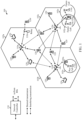
- FIG. 1 illustrates an example wireless communication network 100 in which aspects of the present disclosure may be performed.
- the wireless communication network 100 may be a New Radio (NR) or 5G network.
- a transmitting device in the wireless communication network 100 such as a UE 120 on the uplink or a BS 110 on the downlink, may be configured to cyclic redundancy check (CRC) polar encoding. If the transmitting device uses an even-weighted CRC generator polynomial, then the resulting CRC codeword is also even-weighted, leading to a cascaded polar output in which the first bit is a dummy bit, independent to the message. Accordingly, the transmitting device may avoid transmission of the dummy bit by using only odd-weighted CRC generator polynomials, dropping the first bit, or applying bit level scrambling to the CRC output before the polar encoding.
- CRC cyclic redundancy check
- the wireless communication network 100 may include a number of base stations (BSs) 110 and other network entities.
- a BS may be a station that communicates with user equipments (UEs).
- Each BS 110 may provide communication coverage for a particular geographic area.
- the term "cell” can refer to a coverage area of a Node B (NB) and/or a NB subsystem serving this coverage area, depending on the context in which the term is used.
- NB Node B
- AP access point
- TRP transmission reception point
- a cell may not necessarily be stationary, and the geographic area of the cell may move according to the location of a mobile BS.
- the base stations may be interconnected to one another and/or to one or more other base stations or network nodes (not shown) in wireless communication network 100 through various types of backhaul interfaces, such as a direct physical connection, a wireless connection, a virtual network, or the like using any suitable transport network.
- any number of wireless networks may be deployed in a given geographic area.
- Each wireless network may support a particular radio access technology (RAT) and may operate on one or more frequencies.
- a RAT may also be referred to as a radio technology, an air interface, etc.
- a frequency may also be referred to as a carrier, a subcarrier, a frequency channel, a tone, a subband, etc.
- Each frequency may support a single RAT in a given geographic area in order to avoid interference between wireless networks of different RATs.
- NR or 5G RAT networks may be deployed.
- a BS may provide communication coverage for a macro cell, a pico cell, a femto cell, and/or other types of cells.
- a macro cell may cover a relatively large geographic area (e.g., several kilometers in radius) and may allow unrestricted access by UEs with service subscription.
- a pico cell may cover a relatively small geographic area and may allow unrestricted access by UEs with service subscription.
- a femto cell may cover a relatively small geographic area (e.g., a home) and may allow restricted access by UEs having an association with the femto cell (e.g., UEs in a Closed Subscriber Group (CSG), UEs for users in the home, etc.).
- CSG Closed Subscriber Group
- a BS for a macro cell may be referred to as a macro BS.
- a BS for a pico cell may be referred to as a pico BS.
- a BS for a femto cell may be referred to as a femto BS or a home BS.
- the BSs 110a, 110b and 110c may be macro BSs for the macro cells 102a, 102b and 102c, respectively.
- the BS 110x may be a pico BS for a pico cell 102x.
- the BSs 110y and 110z may be femto BSs for the femto cells 102y and 102z, respectively.
- a BS may support one or multiple (e.g., three) cells.
- Wireless communication network 100 may also include relay stations.
- a relay station is a station that receives a transmission of data and/or other information from an upstream station (e.g., a BS or a UE) and sends a transmission of the data and/or other information to a downstream station (e.g., a UE or a BS).
- a relay station may also be a UE that relays transmissions for other UEs.
- a relay station 110r may communicate with the BS 110a and a UE 120r in order to facilitate communication between the BS 110a and the UE 120r.
- a relay station may also be referred to as a relay BS, a relay, etc.
- Wireless communication network 100 may be a heterogeneous network that includes BSs of different types, e.g., macro BS, pico BS, femto BS, relays, etc. These different types of BSs may have different transmit power levels, different coverage areas, and different impact on interference in the wireless communication network 100.
- macro BS may have a high transmit power level (e.g., 20 Watts) whereas pico BS, femto BS, and relays may have a lower transmit power level (e.g., 1 Watt).
- Wireless communication network 100 may support synchronous or asynchronous operation.
- the BSs may have similar frame timing, and transmissions from different BSs may be approximately aligned in time.
- the BSs may have different frame timing, and transmissions from different BSs may not be aligned in time.
- the techniques described herein may be used for both synchronous and asynchronous operation.
- a network controller 130 may couple to a set of BSs and provide coordination and control for these BSs.
- the network controller 130 may communicate with the BSs 110 via a backhaul.
- the BSs 110 may also communicate with one another (e.g., directly or indirectly) via wireless or wireline backhaul.
- the UEs 120 may be dispersed throughout the wireless communication network 100, and each UE may be stationary or mobile.
- a UE may also be referred to as a mobile station, a terminal, an access terminal, a subscriber unit, a station, a Customer Premises Equipment (CPE), a cellular phone, a smart phone, a personal digital assistant (PDA), a wireless modem, a wireless communication device, a handheld device, a laptop computer, a cordless phone, a wireless local loop (WLL) station, a tablet computer, a camera, a gaming device, a netbook, a smartbook, an ultrabook, an appliance, a medical device or medical equipment, a biometric sensor/device, a wearable device such as a smart watch, smart clothing, smart glasses, a smart wrist band, smart jewelry (e.g., a smart ring, a smart bracelet, etc.), an entertainment device (e.g., a music device, a
- Some UEs may be considered machine-type communication (MTC) devices or evolved MTC (eMTC) devices.
- MTC and eMTC UEs include, for example, robots, drones, remote devices, sensors, meters, monitors, location tags, etc., that may communicate with a BS, another device (e.g., remote device), or some other entity.
- a wireless node may provide, for example, connectivity for or to a network (e.g., a wide area network such as Internet or a cellular network) via a wired or wireless communication link.
- Some UEs may be considered Internet-of-Things (IoT) devices, which may be narrowband IoT (NB-IoT) devices.
- IoT Internet-of-Things
- NB-IoT narrowband IoT
- Certain wireless networks utilize orthogonal frequency division multiplexing (OFDM) on the downlink and single-carrier frequency division multiplexing (SC-FDM) on the uplink.
- OFDM and SC-FDM partition the system bandwidth into multiple (K) orthogonal subcarriers, which are also commonly referred to as tones, bins, etc.
- K orthogonal subcarriers
- Each subcarrier may be modulated with data.
- modulation symbols are sent in the frequency domain with OFDM and in the time domain with SC-FDM.
- the spacing between adjacent subcarriers may be fixed, and the total number of subcarriers (K) may be dependent on the system bandwidth.
- the spacing of the subcarriers may be 15 kHz and the minimum resource allocation (called a "resource block” (RB)) may be 12 subcarriers (or 180 kHz). Consequently, the nominal Fast Fourier Transfer (FFT) size may be equal to 128, 256, 512, 1024 or 2048 for system bandwidth of 1.25, 2.5, 5, 10, or 20 megahertz (MHz), respectively.
- the system bandwidth may also be partitioned into subbands. For example, a subband may cover 1.08 MHz (i.e., 6 resource blocks), and there may be 1, 2, 4, 8, or 16 subbands for system bandwidth of 1.25, 2.5, 5, 10 or 20 MHz, respectively.
- NR may utilize OFDM with a CP on the uplink and downlink and include support for half-duplex operation using TDD. Beamforming may be supported and beam direction may be dynamically configured. MIMO transmissions with precoding may also be supported. MIMO configurations in the DL may support up to 8 transmit antennas with multi-layer DL transmissions up to 8 streams and up to 2 streams per UE. Multi-layer transmissions with up to 2 streams per UE may be supported. Aggregation of multiple cells may be supported with up to 8 serving cells.
- a scheduling entity (e.g., a BS) allocates resources for communication among some or all devices and equipment within its service area or cell, the scheduling entity may be responsible for scheduling, assigning, reconfiguring, and releasing resources for one or more subordinate entities. That is, for scheduled communication, subordinate entities utilize resources allocated by the scheduling entity.
- Base stations are not the only entities that may function as a scheduling entity, in some examples, a UE may function as a scheduling entity and may schedule resources for one or more subordinate entities (e.g., one or more other UEs), and the other UEs may utilize the resources scheduled by the UE for wireless communication.
- a UE may function as a scheduling entity in a peer-to-peer (P2P) network, and/or in a mesh network.
- P2P peer-to-peer
- UEs may communicate directly with one another in addition to communicating with a scheduling entity.
- a solid line with double arrows indicates desired transmissions between a UE and a serving BS, which is a BS designated to serve the UE on the downlink and/or uplink.
- a finely dashed line with double arrows indicates interfering transmissions between a UE and a BS.
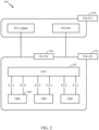
- FIG. 2 illustrates an example logical architecture of a distributed radio access network (RAN) 200, which may be implemented in the wireless communication network 100 illustrated in FIG. 1 .
- a 5G access node 206 may include an access node controller (ANC) 202.
- ANC 202 may be a central unit (CD) of the distributed RAN 200.
- the backhaul interface to the next generation core network (NG-CN) 204 may terminate at ANC 202.
- the backhaul interface to neighboring next generation access nodes (NG-ANs) 210 may terminate at ANC 202.
- ANC 202 may include one or more TRPs 208 (e.g., cells, BSs, gNBs, etc.).
- the TRPs 208 may be a distributed unit (DU). TRPs 208 may be connected to a single ANC (e.g., ANC 202) or more than one ANC (not illustrated). For example, for RAN sharing, radio as a service (RaaS), and service specific AND deployments, TRPs 208 may be connected to more than one ANC. TRPs 208 may each include one or more antenna ports. TRPs 208 may be configured to individually (e.g., dynamic selection) or jointly (e.g., joint transmission) serve traffic to a UE.
- ANC e.g., ANC 202
- RaaS radio as a service
- TRPs 208 may each include one or more antenna ports.
- TRPs 208 may be configured to individually (e.g., dynamic selection) or jointly (e.g., joint transmission) serve traffic to a UE.
- the logical architecture of distributed RAN 200 may support fronthauling solutions across different deployment types.
- the logical architecture may be based on transmit network capabilities (e.g., bandwidth, latency, and/or jitter).
- next generation access node (NG-AN) 210 may support dual connectivity with NR and may share a common fronthaul for LTE and NR.
- NG-AN next generation access node
- the logical architecture of distributed RAN 200 may enable cooperation between and among TRPs 208, for example, within a TRP and/or across TRPs via ANC 202.
- An inter-TRP interface may not be used.
- Logical functions may be dynamically distributed in the logical architecture of distributed RAN 200.
- the Radio Resource Control (RRC) layer Packet Data Convergence Protocol (PDCP) layer, Radio Link Control (RLC) layer, Medium Access Control (MAC) layer, and a Physical (PHY) layers may be adaptably placed at the DU (e.g., TRP 208) or CU (e.g., ANC 202).
- RRC Radio Resource Control
- PDCP Packet Data Convergence Protocol
- RLC Radio Link Control
- MAC Medium Access Control
- PHY Physical
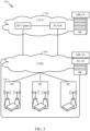
- FIG. 3 illustrates an example physical architecture of a distributed RAN 300, according to aspects of the present disclosure.
- a centralized core network unit (C-CU) 302 may host core network functions.
- C-CU 302. may be centrally deployed.
- C-CU 302 functionality may be offloaded (e.g., to advanced wireless services (AWS)), in an effort to handle peak capacity.
- AWS advanced wireless services
- a centralized RAN unit (C-RU) 304 may host one or more ANC functions.
- the C-RU 304 may host core network functions locally.
- the C-RU 304 may have distributed deployment.
- the C-RU 304 may be close to the network edge.
- a DU 306 may host one or more TRPs (edge node (EN), an edge unit (EU), a radio head (RH), a smart radio head (SRH), or the like).
- the DU may be located at edges of the network with radio frequency (RF) functionality.
- RF radio frequency
- FIG. 4 illustrates example components of BS 110 and UE 120 (as depicted in FIG. 1 ), which may be used to implement aspects of the present disclosure.
- antennas 452, processors 466, 458, 464, and/or controller/processor 480 of the UE 120 and/or antennas 434, processors 420, 430, 438, and/or controller/processor 440 of the BS 110 may be used to perform the various techniques and methods described herein for CRC concatenated polar codes.
- a transmit processor 420 may receive data from a data source 412 and control information from a controller/processor 440.
- the control information may be for the Physical Broadcast Channel (PBCH), Physical Control Format Indicator Channel (PCFICH), Physical Hybrid ARQ Indicator Channel (PHICH), Physical Downlink Control Channel (PDCCH), group common PDCCH (GC PDCCH), etc.
- the data may be for the Physical Downlink Shared Channel (PDSCH), etc.
- the processor 420 may process (e.g., encode and symbol map) the data and control information to obtain data symbols and control symbols, respectively.
- the processor 420 may also generate reference symbols, e.g., for the primary synchronization signal (PSS), secondary synchronization signal (SSS), and cell-specific reference signal (CRS).
- a transmit (TX) multiple-input multiple-output (MIMO) processor 430 may perform spatial processing (e.g., precoding) on the data symbols, the control symbols, and/or the reference symbols, if applicable, and may provide output symbol streams to the modulators (MODs) 432a through 432t. Each modulator 432 may process a respective output symbol stream (e.g., for OFDM, etc.) to obtain an output sample stream.
- Each modulator may further process (e.g., convert to analog, amplify, filter, and upconvert) the output sample stream to obtain a downlink signal.
- Downlink signals from modulators 432a through 432t may be transmitted via the antennas 434a through 434t, respectively.
- the antennas 452a through 452r may receive the downlink signals from the base station 110 and may provide received signals to the demodulators (DEMODs) in transceivers 454a through 454r, respectively.
- Each demodulator 454 may condition (e.g., filter, amplify, downconvert, and digitize) a respective received signal to obtain input samples.
- Each demodulator may further process the input samples (e.g., for OFDM, etc.) to obtain received symbols.
- a MIMO detector 456 may obtain received symbols from all the demodulators 454a through 454r, perform MIMO detection on the received symbols if applicable, and provide detected symbols.
- a receive processor 458 may process (e.g., demodulate, deinterleave, and decode) the detected symbols, provide decoded data for the UE 120 to a data sink 460, and provide decoded control information to a controller/processor 480.
- a transmit processor 464 may receive and process data (e.g., for the Physical Uplink Shared Channel (PUSCH)) from a data source 462 and control information (e.g., for the Physical Uplink Control Channel (PUCCH) from the controller/processor 480.
- the transmit processor 464 may also generate reference symbols for a reference signal (e.g., for the sounding reference signal (SRS)).
- the symbols from the transmit processor 464 may be precoded by a TX MIMO processor 466 if applicable, further processed by the demodulators in transceivers 454a through 454r (e.g., for SC-FDM, etc.), and transmitted to the base station 110.
- data e.g., for the Physical Uplink Shared Channel (PUSCH)
- control information e.g., for the Physical Uplink Control Channel (PUCCH) from the controller/processor 480.
- the transmit processor 464 may also generate reference symbols for a reference signal (e.g., for the sounding reference signal (
- the uplink signals from the UE 120 may be received by the antennas 434, processed by the modulators 432, detected by a MIMO detector 436 if applicable, and further processed by a receive processor 438 to obtain decoded data and control information sent by the UE 120.
- the receive processor 438 may provide the decoded data to a data sink 439 and the decoded control information to the controller/processor 440.
- the controllers/processors 440 and 480 may direct the operation at the BS 110 and the UE 120, respectively.
- the processor 440 and/or other processors and modules at the BS 110 may perform or direct the execution of processes for tire techniques described herein.
- the memories 442 and 482 may store data and program codes for BS 110 and UE 120, respectively.
- a scheduler 444 may schedule UEs for data transmission on the downlink and/or uplink.
- FIG. 5 illustrates a diagram 500 showing examples for implementing a communications protocol stack, according to aspects of the present disclosure.
- the illustrated communications protocol stacks may be implemented by devices operating in a wireless communication system, such as a 5G system (e.g., a system that supports uplink-based mobility).
- Diagram 500 illustrates a communications protocol stack including a RRC layer 510, a PDCP layer 515, a RLC layer 520, a MAC layer 525, and a PHY layer 530.
- the layers of a protocol stack may be implemented as separate modules of software, portions of a processor or ASIC, portions of non-collocated devices connected by a communications link, or various combinations thereof. Collocated and non-collocated implementations may be used, for example, in a protocol stack for a network access device (e.g., ANs, CUs, and/or DUs) or a UE.
- a network access device e.g., ANs, CUs, and/or
- a first option 505-a shows a split implementation of a protocol stack, in which implementation of the protocol stack is split between a centralized network access device (e.g., an ANC 202 in FIG. 2 ) and distributed network access device (e.g., DU 208 in FIG. 2 ).
- a centralized network access device e.g., an ANC 202 in FIG. 2
- distributed network access device e.g., DU 208 in FIG. 2
- an RRC layer 510 and a PDCP layer 515 may be implemented by the central unit
- an RLC layer 520, a MAC layer 525, and a PHY layer 530 may be implemented by the DU.
- the CU and the DU may be collocated or non-collocated.
- the first option 505--a may be useful in a macro cell, micro cell, or pico cell deployment.
- a second option 505--b shows a unified implementation of a protocol stack, in which the protocol stack is implemented in a single network access device.
- RRC layer 510, PDCP layer 515, RLC layer 520, MAC layer 525, and PHY layer 530 may each be implemented by the AN.
- the second option 505-b may be useful in, for example, a femto cell deployment.
- a UE may implement an entire protocol stack as shown in 505-c (e.g., the RRC layer 510, the PDCP layer 515, the RLC layer 520, the MAC layer 525, and the PHY layer 530).
- the basic transmission time interval (TTI) or packet duration is the 1 ms subframe.
- a subframe is still 1 ms, but the basic TTI is referred to as a slot.
- a subframe contains a variable number of slots (e.g., 1, 2, 4, 8, 16, ... slots) depending on the subcarrier spacing.
- the NR RB is 12 consecutive frequency subcarriers.
- NR may support a base subcarrier spacing of 15 KHz and other subcarrier spacing may be defined with respect to the base subcarrier spacing, for example, 30 kHz, 60 kHz, 120 kHz, 240 kHz, etc.
- the symbol and slot lengths scale with the subcarrier spacing.
- the CP length also depends on the subcarrier spacing.
- FIG. 6 is a diagram showing an example of a frame format 600 for NR.
- the transmission timeline for each of the downlink and uplink may be partitioned into units of radio frames.
- Each radio frame may have a predetermined duration (e.g., 10 ms) and may be partitioned into 10 subframes, each of 1 ms, with indices of 0 through 9.
- Each subframe may include a variable number of slots depending on the subcarrier spacing.
- Each slot may include a variable number of symbol periods (e.g., 7 or 14 symbols) depending on the subcarrier spacing.
- the symbol periods in each slot may be assigned indices.
- a mini-slot which may be referred to as a sub-slot structure, refers to a transmit time interval having a duration less than a slot (e.g., 2, 3, or 4 symbols).
- Each symbol in a slot may indicate a link direction (e.g., DL, UL, or flexible) for data transmission and the link direction for each subframe may be dynamically switched.
- the link directions may be based on the slot format.
- Each slot may include DL/UL data as well as DL/UL control information.
- a synchronization signal (SS) block is transmitted.
- the SS block includes a PSS, a SSS, and a two symbol PBCH.
- the SS block can be transmitted in a fixed slot location, such as the symbols 0-3 as shown in FIG. 6 .
- the PSS and SSS may be used by UEs for cell search and acquisition.
- the PSS may provide half-frame timing, the SS may provide the CP length and frame timing.
- the PSS and SSS may provide the cell identity.
- the PBCH carries some basic system information, such as downlink system bandwidth, timing information within radio frame, SS burst set periodicity. system frame number, etc.
- the SS blocks may be organized into SS bursts to support beam sweeping.
- Further system information such as, remaining minimum system information (RMSI), system information blocks (SIBs), other system information (OSI) can be transmitted on a physical downlink shared channel (PDSCH) in certain subframes.
- the SS block can be transmitted up to sixty-four times, for example, with up to sixty-four different beam directions for mmW.
- the up to sixty-four transmissions of the SS block are referred to as the SS burst set.
- SS blocks in an SS burst set are transmitted in the same frequency region, while SS blocks in different SS bursts sets can be transmitted at different frequency locations.
- two or more subordinate entities may communicate with each other using sidelink signals.
- Real-world applications of such sidelink communications may include public safety, proximity services, UE-to-network relaying, vehicle-to-vehicle (V2V) communications, Internet of Everything (IoE) communications, loT communications, mission-critical mesh, and/or various other suitable applications.
- a sidelink signal may refer to a signal communicated from one subordinate entity (e.g., UE1) to another subordinate entity (e.g., UE2) without relaying that communication through the scheduling entity (e.g., UE or BS), even though the scheduling entity may be utilized for scheduling and/or control purposes.
- the sidelink signals may be communicated using a licensed spectrum (unlike wireless local area networks, which typically use an unlicensed spectrum).
- a UE may operate in various radio resource configurations, including a configuration associated with transmitting pilots using a dedicated set of resources (e.g., a radio resource control (RRC) dedicated state, etc.) or a configuration associated with transmitting pilots using a common set of resources (e.g., an RRC common state, etc.).
- RRC radio resource control
- the UE may select a dedicated set of resources for transmitting a pilot signal to a network.
- the UE may select a common set of resources for transmitting a pilot signal to the network.
- a pilot signal transmitted by the UE may be received by one or more network access devices, such as an AN, or a DU, or portions thereof.
- Each receiving network access device may be configured to receive and measure pilot signals transmitted on the common set of resources, and also receive and measure pilot signals transmitted on dedicated sets of resources allocated to the UEs for which the network access device is a member of a monitoring set of network access devices for the UE.
- One or more of the receiving network access devices, or a CU to which receiving network access device(s) transmit the measurements of the pilot signals may use the measurements to identify serving cells for the UEs, or to initiate a change of serving cell for one or more of the UEs.
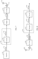
- FIG. 7 illustrates a portion of a radio frequency (RF) modem 704 that may be configured to provide an encoded message for wireless transmission (e.g., using CRC concatenated polar codes described below).
- RF radio frequency
- an encoder in a transmitting device such as a base station (e.g., BS 110) on the downlink or a UE (e.g., UE 120) on the uplink, receives a message 702 for transmission.
- the message 702 may contain data (e.g., information bits) and/or encoded voice or other content directed to the receiving device.
- the encoder 706 encodes the message using a suitable modulation and coding scheme (MCS), typically selected based on a configuration defined by the BS 110 or another network entity.
- MCS modulation and coding scheme
- the encoder 706 may be configured to encode the message 702 using techniques presented herein.
- the encoded bitstream 708 (e.g., representing to the encoded message 702) may then be provided to a mapper 710 that generates a sequence of Tx symbols 712 that are modulated, amplified and otherwise processed by Tx chain 714 to produce an RF signal 716 for transmission through antenna 718.
- FIG. 8 illustrates a portion of a RF modem 810 that may be configured to receive and decode a wirelessly transmitted signal including an encoded message (e.g., a message encoded using techniques presented herein).
- the modem 810 receiving the signal may reside at the receiving device, such as the UE 120 on the downlink or the BS 110 on the uplink, or at any other suitable apparatus or means for carrying out the described functions.
- An antenna 802 provides the RF signal 716 to the receiving device.
- An Rx chain 806 processes and demodulates the RF signal 716 and may provide a sequence of symbols 808 to a demapper 812, which produces a sequence of a-priori probabilities 814, often represented as log-likelihood ratios (LLRs) corresponding to the encoded message.
- a decoder 816 may then be used to decode m-bit information strings from a bitstream that has been encoded using a coding scheme (e.g., as described herein).
- the decoder 816 may comprise a CRC concatenated polar decoder.
- the encoder 706 may be a CRC concatenated polar encoder.
- encoder 906 may include a CRC outer code encoder 906a and polar inner code encoder 906b.
- the encoder 906 may receive the payload of K information bits to be transmitted and the CRC outer code encoder 906a may add CRC bits and output K+r CRC encoded bits to the polar inner code encoder 906b.
- the polar inner code encoder 906b uses polar code and produces N polar encoded bits.
- decoder 1016 may include a polar decoder 1016a and CRC decoder 1016b as shown in FIG. 10 .
- Polar codes have been adopted for error-correction in NR systems. Polar codes may be used to encode a stream of bits for transmission. Polar codes are a capacity-achieving coding scheme with almost linear (in block length) encoding and decoding complexity. Polar codes have many desirable properties such as deterministic construction (e.g., based on a fast Hadamard transform), very low and predictable error floors, and simple successive-cancellation (SC) based decoding.
- deterministic construction e.g., based on a fast Hadamard transform
- SC successive-cancellation
- G ⁇ 3 G 2 0
- G 2 1 0 0 0 1 1 0 0 1 0 1 1 1 1 1 1
- the frozen bits may be selected as the least reliable bits (e.g., the rows with the lowest weight).
- u (0, 0, 0, u 3 , 0, u 5 , u 6 , u 7 ) with u 0 , u 1 , u 2 , and u 4 set as frozen bits.
- G 1 1 1 1 1 0 0 0 0 1 1 0 0 1 1 0 0 1 0 0 1 0 1 0 1 0 1 0 1 0 1 0 1 0 1 0 1 0 1 0 1 0 1 0 1 0 1 0 1 1 1 1 1 1 1 1 1 1 1 1 1 1 1 1 1 1 1 1 1 1 1 1 1 1 1 1 1 1 1 1 1 1 1 1 1 1 1 1 1 1 1 1 1 1 1 1 1 1 1 1 1 1 1 1 1 1 1 1 1 1 1 1 1 1 1 1 1 1 1 1 1 1 1 1 1 1 1 1 1 1 1 1 1 1 1 1 1 1 1 1 1 1 1 1 1 1 1
- every estimated bit, û i has a predetermined error probability given that bits û 0 -û i-1 were correctly decoded, that, for extremely large code size N, tends towards either 0 or 0.5. Moreover, the proportion of estimated bits with a low error probability tends towards the capacity of the underlying channel.
- Polar codes exploit this phenomenon, called channel polarization, by using the most reliable K bits to transmit information, while setting to a predetermined value (such as 0), also referred to as freezing, the remaining (N-K) bits, for example as explained below.
- Polar codes transform the channel into N parallel "virtual" channels for the N information and frozen bits. If C is the capacity of the channel, then, for sufficiently large values of N, there are almost N*C channels which are extremely reliable and there are almost N(1 - C) channels which are extremely unreliable.
- the basic polar coding scheme then involves freezing (i.e., setting to a known value, such as zero) the input bits in u corresponding to the unreliable channels, while placing information bits only in the bits of u corresponding to reliable channels. For short-to-medium N, this polarization may not be complete in the sense there could be several channels which are neither completely unreliable nor completely reliable (i.e., channels that are marginally reliable). Depending on the rate of transmission, bits corresponding to these marginally reliable channels may be either frozen or used for information bits.
- a Polar decoder employs the successive cancellation (SC) or successive cancellation list (SCL) decoding algorithm.
- SC decoding algorithm essentially operates by performing a recursive depth-first traversal of a decoding tree, to convert the bitstream 814 (e.g., a sequence of LLRs) into the message 818 corresponding to the message 702 (e.g., when the decoding is successful).
- CRC concatenated polar coding may be performed, whereby the encoder 706 first performed CRC encoding on the K information bits to produce K+r (information bits + checksums) CRC encoded bits and then polar encodes the K+r CRC encoded bits to produce N polar encoded bits.
- the CRC outer code encoder 1006a uses generator polynomial for the CRC algorithm.
- an example generator polynomial x 3 + x 2 + 1 can be represented as a binary row vector containing the coefficients in descending orders of power, in this example, [1 1 0 1].
- tire first code bit x[1] is equal to the modulo-2 sum of all of the CRC output bits-regardless of the selected information bit locations of the polar code.
- CRC code is a cyclic code
- a given CRC generator polynomial g ( X ) X r + .... + 1
- the first code bit x[1] (which may be the modulo-2 sum of the CRC encoded bits) in the cascaded polar output (the N polar encoded bits) always equals to a dummy bit (e.g., always a fixed value, such as "0"), which is independent to the message (the K information bits input to the CRC encoder).
- a dummy bit e.g., always a fixed value, such as "0”
- polar codes are a relatively recent breakthrough in coding theory and have been proven to achieve Shannon capacity for large values of a code block size N, whereas for smaller code block sizes, polar codes may suffer from poor minimum distance.
- Techniques such as successive cancellation list (SCL) decoding, leverage a simple outer code having excellent minimum distance, such as a cyclic redundancy check (CRC) or parity-check, on top of a polar inner code, such that the combined code has excellent minimum distance.
- CRC cyclic redundancy check
- parity-check parity-check
- aspects of the present disclosure propose techniques for avoiding transmission of dummy bits in CRC concatenated polar codes. For example, in some cases, only odd-weighted CRC generator polynomials may be selected. In some cases, when even-weighted CRC generator polynomials are used, the dummy bit may be discarded, and/or bit-level scrambling can be performed on the CRC bits to avoid generation of the dummy bit. Thereby, the encoding can achieve the benefits of minimum distance, while avoiding the transmission of dummy bits.
- FIG. 11 , FIG. 13 , and FIG. 15 illustrate example operations 1100, 1300, and 1500, respectively, for encoding bits of information, for example, for CRC concatenated polar encoding that avoids transmission of dummy bits, in accordance with certain aspects of the present disclosure.
- operations 1100, 1300, and/or 1500 may be performed by any suitable encoding device, such as a base station (e.g., a BS 110 in the wireless communication network 100) on the downlink or a user equipment (e.g., a UE 120 in the wireless communication network 100) on the uplink.
- a base station e.g., a BS 110 in the wireless communication network 100
- a user equipment e.g., a UE 120 in the wireless communication network 100
- the encoding device may include one or more components as illustrated in FIGs. 4 , 7 , 9 , 12 , 14 , 16 , and/or 18 which may be configured to perform the operations described herein.
- the antenna 434, modulator/demodulator 432, transmit processor 420, controller/processor 440, and/or memory 442 of the BS 110, as illustrated in FIG. 4 may perform the operations described herein.
- the antenna 452, demodulator/modulator 454, transmit processor 464, controller/processor 480, and/or memory 482 of the UE 120, as illustrated in FIG. 4 may perform the operations described herein.
- the encoder 906, mapper 910, TX Chain 914, and/or antenna 918 as illustrated in FIG. 9 may be configured to perform the operations described herein.
- complementary operations to the operations 1100, 1300, and 1500 may be performed for decoding bits of information.
- the complementary operations may, for example, be performed by any suitable decoding device, such as a BS (e.g., BS 110 in the wireless communication network 100) on the uplink and/or a UE (e.g., UE 120 in the wireless communication network 100) on the downlink.
- the decoding device may include one or more components as illustrated in FIGs. 4 , 8 , and 10 which may be configured to perform the operations described herein.
- the antenna 434, modulator/demodulator 432, transmit processor 420, controller/processor 440, and/or memory 442 of the BS 110, as illustrated in FIG. 4 may perform the operations described herein.
- the antenna 452, demodulator/modulator 454, transmit processor 464, controller/processor 480, and/or memory 482. of the UE 120, as illustrated in FIG. 4 may perform the operations described herein. Additionally or alternatively, the decoder 1016, demapper 1012, RX Chain 1006, and/or antenna 1002 as illustrated in FIG. 10 may be configured to perform the complementary operations.
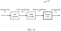
- FIG. 11 illustrates example operations 1100 for CRC concatenated polar encoding bits of information including discarding a dummy bit, in accordance with a claimed embodiment of the present disclosure. Operations 1100 begin, at 1102, by obtaining the bits of information to be transmitted.
- the encoder performs CRC outer encoding of the bits of information using an even-weighted generator polynomial to produce CRC encoded bits.
- the encoder performs polar inner encoding of the CRC encoded bits to generate a codeword.
- the polar encoding may include setting one or more most reliable bits as information bits and setting one or more other bits as frozen bits.
- the encoder discards a first code bit (e.g., the x[1] bit) at a beginning of the codeword to produce a shortened codeword.
- the first code bit is equal to a modulo-2 sum of the CRC encoded bits.
- the first code bit may always be equal to a fixed bit value, such as a "0".
- the first code bit e.g., the x[1] bit
- the first code bit may be a dummy bit. Discarding the first code bit produces the shortened codeword.
- the encoder transmits the shortened codeword in accordance with a radio technology (e.g., 5G) over a channel via one or more antenna elements situated proximate a transmitter.
- a radio technology e.g., 5G
- the transmitting device avoids transmission of the dummy bit and may improve the efficiency of the transmission, while also achieving the improved minimum distance of using CRC polar encoding.
- the encoder 1206 avoids transmission of dummy bits by discarding the x[1] bit of the N output polar encoded bits from the polar encoder. As mentioned above, when an even-weighted CRC generator polynomial is used, this bit is always a bit-0, independent of the K message bits input to the CRC encoder. Thus, discarding this bit may avoid transmission of the dummy bit.
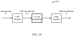
- FIG. 13 illustrates example operations 1300 for CRC concatenated polar encoding bits of information including performing bit-level scrambling of CRC encoded bits, in accordance with certain aspects of the present disclosure. Operations 1300 begin, at 1302, by obtaining the bits of information to be transmitted.
- the encoder performs CRC outer encoding of the bits of information using an even-weighted generator polynomial to produce CRC encoded bits.
- the encoder performs bit scrambling of the CRC encoded bits.
- the bit scrambling may ensure that a first code bit (e.g., the x[1] code bit) at a beginning of the codeword is equal to a non-zero bit at least sometimes.
- the encoder performs polar inner encoding of the scrambled CRC encoded bits to generate a codeword.
- the encoder transmits the codeword in accordance with a radio technology (e.g., 5G) over a channel via one or more antenna elements situated proximate a transmitter.
- a radio technology e.g., 5G
- the transmitting device avoids generation of the dummy bit and may improve the efficiency of the transmission, while also achieving the improved minimum distance of using CRC polar encoding.
- the encoder 1406 may avoid transmission of dummy bits by using bit-level scrambling of the K+r CRC encoded bits output from the CRC encoder-before they are input to the polar encoder.
- bit-level scrambling of the K+r CRC encoded bits output from the CRC encoder-before they are input to the polar encoder.
- the x[1] bit of the N output polar encoded bits is always a bit-0, independent of the K message bits input to the CRC encoder.
- the scrambling may be performed by a bit scrambling module at the encoder 906.
- FIG. 15 illustrates example operations 1500 for CRC concatenated polar encoding bits of information including selecting only odd-weighted CRC generator polynomials, in accordance with certain aspects of the present disclosure. Operations 1500 begin, at 1502, by obtaining the bits of information to be transmitted.
- the encoder selects only odd-weighted generator polynomials for performing CRC outer encoding of the bits of information to produce CRC encoded bits.
- the selection of only odd-weighted polynomials for performing the CRC outer encoding may ensure that a first code bit [e.g., the x[1] code bit) at a beginning of the codeword is equal to a non-zero bit at least sometimes.
- the encoder performs polar inner encoding of the scrambled CRC encoded bits to generate a codeword.
- the encoder transmits the codeword in accordance with a radio technology (e.g., 5G) over a channel via one or more antenna elements situated proximate a transmitter.
- a radio technology e.g., 5G
- the transmitting device avoids generation of the dummy bit and may improve the efficiency of the transmission, while also achieving the improved minimum distance of using CRC polar encoding.
- the encoder 1606 may avoid transmission of dummy bits by selecting odd-weighted CRC generator polynomial for the CRC encoding.
- odd-weighted CRC generator polynomial when an even-weighted CRC generator polynomial is used, the x[1] bit of the N output polar encoded bits is always a bit-0, independent of the K message bits input to the CRC encoder.
- this bit may be non-zero and transmission of the dummy bit can be avoided.
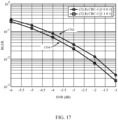
- FIG. 17 is an example graph illustrating encoding performance of various CRC generator polynomials.
- performance for CRC concatenated polar codes using the even-weighted CRC generator polynomial has worse performance than the odd-weighted (curve 1704). Avoiding transmission of dummy bits may improve block error rate (BLER).
- BLER block error rate
- FIG. 18 illustrates a communications device 1800 that may include various components (e.g., corresponding to means-plus-function components) configured to perform operations for the techniques disclosed herein, such as the operations 1100, 1300, and 1500 illustrated in FIGs. 11 , 13 , and 15 , respectively.
- the communications device 1800 includes a processing system 1802 coupled to a transceiver 1808.
- the transceiver 1808 is configured to transmit and receive signals for the communications device 1800 via an antenna 1810, such as the various signals as described herein.
- the processing system 1802 may be configured to perform processing functions for the communications device 1800, including processing signals received and/or to be transmitted by the communications device 1800.
- the processing system 1802 includes a processor 1804 coupled to a computer-readable medium/memory 1812 via a bus 1806.
- the computer-readable medium/memory 1812 is configured to store instructions (e.g., computer executable code) that when executed by the processor 1804, cause the processor 1804. to perform the operations illustrated in FIGs. 11 , 13 , and 15 , or other operations for performing the various techniques discussed herein for avoiding transmission of dummy bits in CRC polar encoding.
- computer-readable medium/memory 1812 stores code 1814 for obtaining information bits.
- the computer readable medium/memory 1812 stores code 1816 for CRC outer encoding.
- the code 1816 for CRC outer encoding may include code for selecting the CRC-generator polynomial (e.g., for selecting only odd-weighted polynomials in some cases).
- the computer readable medium/memory 1812 may store code 1818 for bit scrambling (e.g., if an even-weighted polynomial is selected).
- the computer readable medium/memory 1812 stores code 1820 for polar inner encoding.
- the computer readable medium/memory 1812 may store code 1822 for discarding a first code bit (e.g., if an even-weighted polynomial is selected).
- the computer readable medium/memory 1812 stores code 1824 for transmitting the codeword.
- the processor 1804 has circuitry configured to implement the code stored in the computer-readable medium/memory 1812.
- the processor 1804 includes encoder circuitry 1826.
- the encoder circuitry 1826 includes circuitry 1828 for obtaining information bits; circuitry 1830 for CRC outer encoding; and circuitry 1834 for polar inner encoding.
- the circuitry 1830 for CRC outer encoding may include circuitry for generator polynomial selection (e.g., for selecting only odd-weighted polynomials in some cases).
- the encoder circuitry 1826 may include circuitry 1832 for bit scrambling (e.g., if an even-weighted polynomial is selected).
- the encoder circuitry 1826 may include circuitry 1836 for discarding a first code bit (e.g., if an even-weighted polynomial is selected).
- the terms distributed, inserted, interleaved may be used interchangeably and generally refer to the strategic placement of outer-code bits within an information stream inputted into an encoder, such as a Polar encoder.
- an encoder such as a Polar encoder.
- aspects of the present disclosure propose techniques for reducing the search space of nodes in a polar decoding tree with relation to wireless communication system, the techniques presented herein are not limited to such wireless communication system.
- the techniques presented herein may equally apply to any other system that uses encoding schemes, such as data storage or compression, or fiber communication systems, hard-wire "copper” communication systems, and the like.
- a phrase referring to "at least one of" a list of items refers to any combination of those items, including single members.
- "at least one of: a, b, or c” is intended to cover a, b, c, a-b, a-c, b-c, and a-b-c, as well as any combination with multiples of the same element (e.g., a-a, a-a-a, a-a-b, a-a-c, a-b-b, a-c-c, b-b, b-b-b, b-b-c, c-c, and c-c-c or any other ordering of a, b, and c).
- determining encompasses a wide variety of actions. For example, “determining” may include calculating, computing, processing, deriving, investigating, looking up (e.g., looking up in a table, a database or another data structure), ascertaining and the like. Also, “determining” may include receiving (e.g., receiving information), accessing (e.g., accessing data in a memory) and the like. Also, “determining” may include resolving, selecting, choosing, establishing and the like.
- the various operations of methods described above may be performed by any suitable means capable of performing the corresponding functions.
- the means may include various hardware and/or software component(s) and/or module(s), including, but not limited to a circuit, an application specific integrated circuit (ASIC), or processor.
- ASIC application specific integrated circuit
- DSP digital signal processor
- ASIC application specific integrated circuit
- FPGA field programmable gate array
- PLD programmable logic device
- a general-purpose processor may be a microprocessor, but in the alternative, the processor may be any commercially available processor, controller, microcontroller, or state machine.
- a processor may also be implemented as a combination of computing devices, e.g., a combination of a DSP and a microprocessor, a plurality of microprocessors, one or more microprocessors in conjunction with a DSP core, or any other such configuration.
- an example hardware configuration may comprise a processing system in a wireless node.
- the processing system may be implemented with a bus architecture.
- the bus may include any number of interconnecting buses and bridges depending on the specific application of the processing system and the overall design constraints.
- the bus may link together various circuits including a processor, machine-readable media, and a bus interface.
- the bus interface may be used to connect a network adapter, among other things, to the processing system via the bus.
- the network adapter may be used to implement the signal processing functions of the PHY layer.
- a user interface e.g., keypad, display, mouse, joystick, etc.
- the bus may also link various other circuits such as timing sources, peripherals, voltage regulators, power management circuits, and the like, which are well known in the art, and therefore, will not be described any further.
- the processor may be implemented with one or more general-purpose and/or special-purpose processors. Examples include microprocessors, microcontrollers, DSP processors, and other circuitry that can execute software. Those skilled in the art will recognize how best to implement the described functionality for the processing system depending on the particular application and the overall design constraints imposed on the overall system.
- the functions may be stored or transmitted over as one or more instructions or code on a computer readable medium.
- Software shall be construed broadly to mean instructions, data, or any combination thereof, whether referred to as software, firmware, middleware, microcode, hardware description language, or otherwise.
- Computer-readable media include both computer storage media and communication media including any medium that facilitates transfer of a computer program from one place to another.
- the processor may be responsible for managing the bus and general processing, including the execution of software modules stored on the machine-readable storage media.
- a computer-readable storage medium may be coupled to a processor such that the processor can read information from, and write information to, the storage medium. In the alternative, the storage medium may be integral to the processor.
- the machine-readable media may include a transmission line, a carrier wave modulated by data, and/or a computer readable storage medium with instructions stored thereon separate from the wireless node, all of which may be accessed by the processor through the bus interface.
- the machine-readable media, or any portion thereof may be integrated into the processor, such as the case may be with cache and/or general register files.
- Examples of machine-readable storage media may include, by way of example, RAM (Random Access Memory), flash memory, ROM (Read Only Memory), PROM (Programmable Read-.
- EPROM Erasable Programmable Read-Only Memory
- EEPROM Electrically Erasable Programmable Read-Only Memory
- registers magnetic disks, optical disks, hard drives, or any other suitable storage medium, or any combination thereof.
- the machine-readable media may be embodied in a computer--program product.
- a software module may comprise a single instruction, or many instructions, and may be distributed over several different code segments, among different programs, and across multiple storage media.
- the computer-readable media may comprise a number of software modules.
- the software modules include instructions that, when executed by an apparatus such as a processor, cause the processing system to perform various functions.
- the software modules may include a transmission module and a receiving module. Each software module may reside in a single storage device or be distributed across multiple storage devices.
- a software module may be loaded into RAM from a hard drive when a triggering event occurs.
- the processor may load some of the instructions into cache to increase access speed.
- One or more cache lines may then be loaded into a general register file for execution by the processor.
- any connection is properly termed a computer-readable medium.
- the software is transmitted from a website, server, or other remote source using a coaxial cable, fiber optic cable, twisted pair, digital subscriber line (DSL), or wireless technologies such as infrared (IR), radio, and microwave
- the coaxial cable, fiber optic cable, twisted pair, DSL, or wireless technologies such as infrared, radio, and microwave are included in the definition of medium.
- Disk and disc include compact disc (CD), laser disc, optical disc, digital versatile disc (DVD), floppy disk, and Blu-ray ® disc where disks usually reproduce data magnetically, while discs reproduce data optically with lasers.
- computer-readable media may comprise non-transitory computer-readable media (e.g., tangible media).
- computer-readable media may comprise transitory computer-readable media (e.g., a signal). Combinations of the above should also be included within the scope of computer-readable media.
- certain aspects may comprise a computer program product for performing the operations presented herein.
- a computer program product may comprise a computer-readable medium having instructions stored (and/or encoded) thereon, the instructions being executable by one or more processors to perform the operations described herein.
- instructions for performing the operations described herein and illustrated in FIG. 11 , FIG. 13 , and FIG. 15 are examples of instructions for performing the operations described herein and illustrated in FIG. 11 , FIG. 13 , and FIG. 15 .
- modules and/or other appropriate means for performing the methods and techniques described herein can be downloaded and/or otherwise obtained by a user terminal and/or base station as applicable.
- a user terminal and/or base station can be coupled to a server to facilitate the transfer of means for performing the methods described herein.
- various methods described herein can be provided via storage means (e.g., RAM, ROM, a physical storage medium such as a compact disc (CD) or floppy disk, etc.), such that a user terminal and/or base station can obtain the various methods upon coupling or providing the storage means to the device.
- storage means e.g., RAM, ROM, a physical storage medium such as a compact disc (CD) or floppy disk, etc.
- CD compact disc
- floppy disk etc.
- any other suitable technique for providing the methods and techniques described herein to a device can be utilized.
Landscapes
- Engineering & Computer Science (AREA)
- Physics & Mathematics (AREA)
- Probability & Statistics with Applications (AREA)
- Theoretical Computer Science (AREA)
- Signal Processing (AREA)
- Computer Networks & Wireless Communication (AREA)
- Mathematical Physics (AREA)
- General Physics & Mathematics (AREA)
- Pure & Applied Mathematics (AREA)
- Mathematical Optimization (AREA)
- Mathematical Analysis (AREA)
- Computational Mathematics (AREA)
- Algebra (AREA)
- Computing Systems (AREA)
- Mobile Radio Communication Systems (AREA)
- Error Detection And Correction (AREA)
Priority Applications (1)
| Application Number | Priority Date | Filing Date | Title |
|---|---|---|---|
| EP24204009.5A EP4462688A3 (en) | 2017-11-07 | 2018-09-21 | Methods and apparatus for crc concatenated polar encoding |
Applications Claiming Priority (2)
| Application Number | Priority Date | Filing Date | Title |
|---|---|---|---|
| PCT/CN2017/109694 WO2019090468A1 (en) | 2017-11-07 | 2017-11-07 | Methods and apparatus for crc concatenated polar encoding |
| PCT/CN2018/107129 WO2019091234A1 (en) | 2017-11-07 | 2018-09-21 | Methods and apparatus for crc concatenated polar encoding |
Related Child Applications (1)
| Application Number | Title | Priority Date | Filing Date |
|---|---|---|---|
| EP24204009.5A Division EP4462688A3 (en) | 2017-11-07 | 2018-09-21 | Methods and apparatus for crc concatenated polar encoding |
Publications (3)
| Publication Number | Publication Date |
|---|---|
| EP3707843A1 EP3707843A1 (en) | 2020-09-16 |
| EP3707843A4 EP3707843A4 (en) | 2021-10-20 |
| EP3707843B1 true EP3707843B1 (en) | 2024-10-30 |
Family
ID=66437474
Family Applications (2)
| Application Number | Title | Priority Date | Filing Date |
|---|---|---|---|
| EP18875500.3A Active EP3707843B1 (en) | 2017-11-07 | 2018-09-21 | Methods and apparatus for crc concatenated polar encoding |
| EP24204009.5A Pending EP4462688A3 (en) | 2017-11-07 | 2018-09-21 | Methods and apparatus for crc concatenated polar encoding |
Family Applications After (1)
| Application Number | Title | Priority Date | Filing Date |
|---|---|---|---|
| EP24204009.5A Pending EP4462688A3 (en) | 2017-11-07 | 2018-09-21 | Methods and apparatus for crc concatenated polar encoding |
Country Status (8)
| Country | Link |
|---|---|
| US (2) | US11196444B2 (enExample) |
| EP (2) | EP3707843B1 (enExample) |
| JP (2) | JP7254788B2 (enExample) |
| KR (2) | KR102694628B1 (enExample) |
| CN (1) | CN111373672B (enExample) |
| BR (1) | BR112020008918A2 (enExample) |
| SG (1) | SG11202002643XA (enExample) |
| WO (2) | WO2019090468A1 (enExample) |
Families Citing this family (13)
| Publication number | Priority date | Publication date | Assignee | Title |
|---|---|---|---|---|
| EP4089941A1 (en) * | 2017-05-05 | 2022-11-16 | Telefonaktiebolaget LM Ericsson (publ) | Polar coding for beam sweeping broadcast channel |
| WO2019090468A1 (en) | 2017-11-07 | 2019-05-16 | Qualcomm Incorporated | Methods and apparatus for crc concatenated polar encoding |
| US11923924B2 (en) * | 2018-02-26 | 2024-03-05 | Parallel Wireless, Inc. | Miniature antenna array with polar combining architecture |
| CN113169767A (zh) | 2018-07-30 | 2021-07-23 | 盈诺飞公司 | 大规模mimo通信系统和方法 |
| CN111988044B (zh) * | 2019-07-01 | 2022-07-19 | 中南大学 | 一种凿孔Polar码的码字构造方法 |
| US11792824B2 (en) * | 2020-03-30 | 2023-10-17 | Qualcomm Incorporated | Multicast feedback and retransmission for transport block grouping |
| CN113810061B (zh) * | 2020-06-17 | 2025-03-04 | 华为技术有限公司 | Polar码编码方法、Polar码译码方法及其装置 |
| US11528035B2 (en) * | 2020-07-13 | 2022-12-13 | Mediatek Inc. | Bit selection for polar coding incremental-redundancy HARQ |
| US11677500B2 (en) * | 2020-09-30 | 2023-06-13 | Polaran Haberlesme Teknolojileri Anonim Sirketi | Methods and apparatus for encoding and decoding of data using concatenated polarization adjusted convolutional codes |
| US11265019B1 (en) * | 2020-12-01 | 2022-03-01 | Huawei Technologies Co., Ltd. | Parallel polar code with shared data and cooperative decoding |
| US11515964B2 (en) * | 2021-01-29 | 2022-11-29 | Huawei Technologies Co., Ltd. | Systems and methods for using not perfectly polarized bit channels in parallel polar codes |
| CN115133936A (zh) * | 2021-03-27 | 2022-09-30 | 华为技术有限公司 | 编码方法、译码方法以及通信装置 |
| WO2025147889A1 (en) * | 2024-01-10 | 2025-07-17 | Qualcomm Incorporated | Frozen cyclic redundancy check bit using a polar code |
Family Cites Families (22)
| Publication number | Priority date | Publication date | Assignee | Title |
|---|---|---|---|---|
| US8745472B2 (en) * | 2012-09-01 | 2014-06-03 | Texas Instruments Incorporated | Memory with segmented error correction codes |
| KR101951663B1 (ko) * | 2012-12-14 | 2019-02-25 | 삼성전자주식회사 | Crc 부호와 극 부호에 의한 부호화 방법 및 장치 |
| RU2013128346A (ru) * | 2013-06-20 | 2014-12-27 | ИЭмСи КОРПОРЕЙШН | Кодирование данных для системы хранения данных на основе обобщенных каскадных кодов |
| JP6178149B2 (ja) | 2013-07-24 | 2017-08-09 | ヤンマー株式会社 | トラクター |
| WO2015026148A1 (ko) * | 2013-08-20 | 2015-02-26 | 엘지전자 주식회사 | 무선 접속 시스템에서 폴라 코딩을 이용한 데이터 송신방법 |
| RU2571587C2 (ru) * | 2014-04-10 | 2015-12-20 | Самсунг Электроникс Ко., Лтд. | Способ и устройство кодирования и декодирования данных в скрученном полярном коде |
| US10193578B2 (en) * | 2014-07-10 | 2019-01-29 | The Royal Institution For The Advancement Of Learning / Mcgill University | Flexible polar encoders and decoders |
| JP2018137491A (ja) | 2015-06-29 | 2018-08-30 | シャープ株式会社 | 端末装置、基地局装置、通信方法、および、集積回路 |
| CN105227189B (zh) | 2015-09-24 | 2019-01-01 | 电子科技大学 | 分段crc辅助的极化码编译码方法 |
| US20180041992A1 (en) | 2016-01-13 | 2018-02-08 | Telefonaktiebolaget Lm Ericsson (Publ) | Control channel for a wireless network |
| US10312947B2 (en) * | 2016-01-21 | 2019-06-04 | Huawei Technologies Co., Ltd. | Concatenated and sliding-window polar coding |
| CN107124188B (zh) * | 2016-02-24 | 2020-08-07 | 华为技术有限公司 | 极化码的编码方法、译码方法、编码设备和译码设备 |
| CN110168979B (zh) * | 2017-01-06 | 2022-07-15 | Idac控股公司 | 基于检错的同步和广播信道 |
| CN108400838B (zh) * | 2017-02-06 | 2021-05-18 | 华为技术有限公司 | 数据处理方法及设备 |
| US10651973B2 (en) * | 2017-03-22 | 2020-05-12 | Huawei Technologies Co., Ltd. | Method and apparatus for error-correction encoding using a polar code |
| CN114553368B (zh) * | 2017-03-22 | 2024-05-17 | 三星电子株式会社 | 在通信或广播系统中使用harq传输的装置和方法 |
| EP3622645B1 (en) * | 2017-05-12 | 2021-11-03 | Telefonaktiebolaget LM Ericsson (publ) | Adaptive crc length for beam sweeping |
| WO2018224982A1 (en) * | 2017-06-06 | 2018-12-13 | Telefonaktiebolaget Lm Ericsson (Publ) | Distributed crc-assisted polar code construction |
| US10998922B2 (en) * | 2017-07-28 | 2021-05-04 | Mitsubishi Electric Research Laboratories, Inc. | Turbo product polar coding with hard decision cleaning |
| CN116054843A (zh) * | 2017-09-11 | 2023-05-02 | 中兴通讯股份有限公司 | 处理ldpc编码数据的方法和装置 |
| WO2019053618A1 (en) * | 2017-09-12 | 2019-03-21 | Telefonaktiebolaget Lm Ericsson (Publ) | CRC INTERLOCKING REASON FOR POLAR CODES |
| WO2019090468A1 (en) | 2017-11-07 | 2019-05-16 | Qualcomm Incorporated | Methods and apparatus for crc concatenated polar encoding |
-
2017
- 2017-11-07 WO PCT/CN2017/109694 patent/WO2019090468A1/en not_active Ceased
-
2018
- 2018-09-21 BR BR112020008918-4A patent/BR112020008918A2/pt unknown
- 2018-09-21 SG SG11202002643XA patent/SG11202002643XA/en unknown
- 2018-09-21 JP JP2020522912A patent/JP7254788B2/ja active Active
- 2018-09-21 KR KR1020207012891A patent/KR102694628B1/ko active Active
- 2018-09-21 WO PCT/CN2018/107129 patent/WO2019091234A1/en not_active Ceased
- 2018-09-21 EP EP18875500.3A patent/EP3707843B1/en active Active
- 2018-09-21 EP EP24204009.5A patent/EP4462688A3/en active Pending
- 2018-09-21 US US16/760,758 patent/US11196444B2/en active Active
- 2018-09-21 KR KR1020247026206A patent/KR102925359B1/ko active Active
- 2018-09-21 CN CN201880071287.3A patent/CN111373672B/zh active Active
-
2021
- 2021-10-27 US US17/512,289 patent/US11770134B2/en active Active
-
2023
- 2023-03-28 JP JP2023051922A patent/JP7571182B2/ja active Active
Also Published As
| Publication number | Publication date |
|---|---|
| KR102694628B1 (ko) | 2024-08-12 |
| US20200343909A1 (en) | 2020-10-29 |
| JP7571182B2 (ja) | 2024-10-22 |
| CN111373672B (zh) | 2024-06-21 |
| EP4462688A3 (en) | 2025-02-26 |
| EP4462688A2 (en) | 2024-11-13 |
| JP2021502016A (ja) | 2021-01-21 |
| EP3707843A1 (en) | 2020-09-16 |
| KR102925359B1 (ko) | 2026-02-09 |
| JP2023078433A (ja) | 2023-06-06 |
| US20220140842A1 (en) | 2022-05-05 |
| EP3707843A4 (en) | 2021-10-20 |
| KR20240123418A (ko) | 2024-08-13 |
| CN111373672A (zh) | 2020-07-03 |
| BR112020008918A2 (pt) | 2020-10-13 |
| WO2019091234A1 (en) | 2019-05-16 |
| KR20200080247A (ko) | 2020-07-06 |
| JP7254788B2 (ja) | 2023-04-10 |
| US11196444B2 (en) | 2021-12-07 |
| SG11202002643XA (en) | 2020-05-28 |
| WO2019090468A1 (en) | 2019-05-16 |
| US11770134B2 (en) | 2023-09-26 |
Similar Documents
| Publication | Publication Date | Title |
|---|---|---|
| US11770134B2 (en) | Methods and apparatus for CRC concatenated polar encoding | |
| CA3046964C (en) | Control channel code rate selection | |
| EP3646468B1 (en) | Crc aided polar coding with avoidance of circular invariance of polar codeword for implicit signaling by circular shifting | |
| EP3738235B1 (en) | Coded-bit allocation for uplink control information (uci) segmentation | |
| EP3721571B1 (en) | Time based redundancy version determination for grant-free signaling | |
| WO2018127172A1 (en) | Rate-matching scheme for control channels using polar codes | |
| EP3711167B1 (en) | Uplink control information segmentation for polar codes | |
| EP3619852B1 (en) | Rate-matching scheme for polar codes | |
| US20190253213A1 (en) | Combining decision metrics of a scrambled payload | |
| EP3665780B1 (en) | Unified pattern for puncturing and shortening polar codes | |
| WO2019136689A1 (en) | Resolutions for aggregation level ambiguity of physical downlink control channel (pdcch) transmissions |
Legal Events
| Date | Code | Title | Description |
|---|---|---|---|
| STAA | Information on the status of an ep patent application or granted ep patent |
Free format text: STATUS: THE INTERNATIONAL PUBLICATION HAS BEEN MADE |
|
| PUAI | Public reference made under article 153(3) epc to a published international application that has entered the european phase |
Free format text: ORIGINAL CODE: 0009012 |
|
| STAA | Information on the status of an ep patent application or granted ep patent |
Free format text: STATUS: REQUEST FOR EXAMINATION WAS MADE |
|
| 17P | Request for examination filed |
Effective date: 20200330 |
|
| AK | Designated contracting states |
Kind code of ref document: A1 Designated state(s): AL AT BE BG CH CY CZ DE DK EE ES FI FR GB GR HR HU IE IS IT LI LT LU LV MC MK MT NL NO PL PT RO RS SE SI SK SM TR |
|
| AX | Request for extension of the european patent |
Extension state: BA ME |
|
| DAV | Request for validation of the european patent (deleted) | ||
| DAX | Request for extension of the european patent (deleted) | ||
| RIC1 | Information provided on ipc code assigned before grant |
Ipc: H04L 1/00 20060101AFI20210701BHEP Ipc: H03M 13/09 20060101ALI20210701BHEP Ipc: H03M 13/13 20060101ALI20210701BHEP |
|
| A4 | Supplementary search report drawn up and despatched |
Effective date: 20210921 |
|
| RIC1 | Information provided on ipc code assigned before grant |
Ipc: H03M 13/13 20060101ALI20210915BHEP Ipc: H03M 13/09 20060101ALI20210915BHEP Ipc: H04L 1/00 20060101AFI20210915BHEP |
|
| STAA | Information on the status of an ep patent application or granted ep patent |
Free format text: STATUS: EXAMINATION IS IN PROGRESS |
|
| 17Q | First examination report despatched |
Effective date: 20230118 |
|
| GRAP | Despatch of communication of intention to grant a patent |
Free format text: ORIGINAL CODE: EPIDOSNIGR1 |
|
| STAA | Information on the status of an ep patent application or granted ep patent |
Free format text: STATUS: GRANT OF PATENT IS INTENDED |
|
| INTG | Intention to grant announced |
Effective date: 20240507 |
|
| GRAS | Grant fee paid |
Free format text: ORIGINAL CODE: EPIDOSNIGR3 |
|
| GRAA | (expected) grant |
Free format text: ORIGINAL CODE: 0009210 |
|
| STAA | Information on the status of an ep patent application or granted ep patent |
Free format text: STATUS: THE PATENT HAS BEEN GRANTED |
|
| AK | Designated contracting states |
Kind code of ref document: B1 Designated state(s): AL AT BE BG CH CY CZ DE DK EE ES FI FR GB GR HR HU IE IS IT LI LT LU LV MC MK MT NL NO PL PT RO RS SE SI SK SM TR |
|
| REG | Reference to a national code |
Ref country code: GB Ref legal event code: FG4D |
|
| REG | Reference to a national code |
Ref country code: CH Ref legal event code: EP |
|
| REG | Reference to a national code |
Ref country code: IE Ref legal event code: FG4D |
|
| REG | Reference to a national code |
Ref country code: DE Ref legal event code: R096 Ref document number: 602018076099 Country of ref document: DE |
|
| REG | Reference to a national code |
Ref country code: LT Ref legal event code: MG9D |
|
| REG | Reference to a national code |
Ref country code: NL Ref legal event code: MP Effective date: 20241030 |
|
| PG25 | Lapsed in a contracting state [announced via postgrant information from national office to epo] |
Ref country code: PT Free format text: LAPSE BECAUSE OF FAILURE TO SUBMIT A TRANSLATION OF THE DESCRIPTION OR TO PAY THE FEE WITHIN THE PRESCRIBED TIME-LIMIT Effective date: 20250228 Ref country code: IS Free format text: LAPSE BECAUSE OF FAILURE TO SUBMIT A TRANSLATION OF THE DESCRIPTION OR TO PAY THE FEE WITHIN THE PRESCRIBED TIME-LIMIT Effective date: 20250228 Ref country code: HR Free format text: LAPSE BECAUSE OF FAILURE TO SUBMIT A TRANSLATION OF THE DESCRIPTION OR TO PAY THE FEE WITHIN THE PRESCRIBED TIME-LIMIT Effective date: 20241030 |
|
| PG25 | Lapsed in a contracting state [announced via postgrant information from national office to epo] |
Ref country code: FI Free format text: LAPSE BECAUSE OF FAILURE TO SUBMIT A TRANSLATION OF THE DESCRIPTION OR TO PAY THE FEE WITHIN THE PRESCRIBED TIME-LIMIT Effective date: 20241030 Ref country code: NL Free format text: LAPSE BECAUSE OF FAILURE TO SUBMIT A TRANSLATION OF THE DESCRIPTION OR TO PAY THE FEE WITHIN THE PRESCRIBED TIME-LIMIT Effective date: 20241030 |
|
| REG | Reference to a national code |
Ref country code: AT Ref legal event code: MK05 Ref document number: 1737954 Country of ref document: AT Kind code of ref document: T Effective date: 20241030 |
|
| PG25 | Lapsed in a contracting state [announced via postgrant information from national office to epo] |
Ref country code: BG Free format text: LAPSE BECAUSE OF FAILURE TO SUBMIT A TRANSLATION OF THE DESCRIPTION OR TO PAY THE FEE WITHIN THE PRESCRIBED TIME-LIMIT Effective date: 20241030 |
|
| PG25 | Lapsed in a contracting state [announced via postgrant information from national office to epo] |
Ref country code: ES Free format text: LAPSE BECAUSE OF FAILURE TO SUBMIT A TRANSLATION OF THE DESCRIPTION OR TO PAY THE FEE WITHIN THE PRESCRIBED TIME-LIMIT Effective date: 20241030 |
|
| PG25 | Lapsed in a contracting state [announced via postgrant information from national office to epo] |
Ref country code: NO Free format text: LAPSE BECAUSE OF FAILURE TO SUBMIT A TRANSLATION OF THE DESCRIPTION OR TO PAY THE FEE WITHIN THE PRESCRIBED TIME-LIMIT Effective date: 20250130 |
|
| PG25 | Lapsed in a contracting state [announced via postgrant information from national office to epo] |
Ref country code: LV Free format text: LAPSE BECAUSE OF FAILURE TO SUBMIT A TRANSLATION OF THE DESCRIPTION OR TO PAY THE FEE WITHIN THE PRESCRIBED TIME-LIMIT Effective date: 20241030 Ref country code: GR Free format text: LAPSE BECAUSE OF FAILURE TO SUBMIT A TRANSLATION OF THE DESCRIPTION OR TO PAY THE FEE WITHIN THE PRESCRIBED TIME-LIMIT Effective date: 20250131 Ref country code: AT Free format text: LAPSE BECAUSE OF FAILURE TO SUBMIT A TRANSLATION OF THE DESCRIPTION OR TO PAY THE FEE WITHIN THE PRESCRIBED TIME-LIMIT Effective date: 20241030 |
|
| PG25 | Lapsed in a contracting state [announced via postgrant information from national office to epo] |
Ref country code: PL Free format text: LAPSE BECAUSE OF FAILURE TO SUBMIT A TRANSLATION OF THE DESCRIPTION OR TO PAY THE FEE WITHIN THE PRESCRIBED TIME-LIMIT Effective date: 20241030 |
|
| PG25 | Lapsed in a contracting state [announced via postgrant information from national office to epo] |
Ref country code: RS Free format text: LAPSE BECAUSE OF FAILURE TO SUBMIT A TRANSLATION OF THE DESCRIPTION OR TO PAY THE FEE WITHIN THE PRESCRIBED TIME-LIMIT Effective date: 20250130 |
|
| PG25 | Lapsed in a contracting state [announced via postgrant information from national office to epo] |
Ref country code: SM Free format text: LAPSE BECAUSE OF FAILURE TO SUBMIT A TRANSLATION OF THE DESCRIPTION OR TO PAY THE FEE WITHIN THE PRESCRIBED TIME-LIMIT Effective date: 20241030 |
|
| PG25 | Lapsed in a contracting state [announced via postgrant information from national office to epo] |
Ref country code: DK Free format text: LAPSE BECAUSE OF FAILURE TO SUBMIT A TRANSLATION OF THE DESCRIPTION OR TO PAY THE FEE WITHIN THE PRESCRIBED TIME-LIMIT Effective date: 20241030 |
|
| PG25 | Lapsed in a contracting state [announced via postgrant information from national office to epo] |
Ref country code: EE Free format text: LAPSE BECAUSE OF FAILURE TO SUBMIT A TRANSLATION OF THE DESCRIPTION OR TO PAY THE FEE WITHIN THE PRESCRIBED TIME-LIMIT Effective date: 20241030 |
|
| PG25 | Lapsed in a contracting state [announced via postgrant information from national office to epo] |
Ref country code: RO Free format text: LAPSE BECAUSE OF FAILURE TO SUBMIT A TRANSLATION OF THE DESCRIPTION OR TO PAY THE FEE WITHIN THE PRESCRIBED TIME-LIMIT Effective date: 20241030 |
|
| PG25 | Lapsed in a contracting state [announced via postgrant information from national office to epo] |
Ref country code: SK Free format text: LAPSE BECAUSE OF FAILURE TO SUBMIT A TRANSLATION OF THE DESCRIPTION OR TO PAY THE FEE WITHIN THE PRESCRIBED TIME-LIMIT Effective date: 20241030 |
|
| PG25 | Lapsed in a contracting state [announced via postgrant information from national office to epo] |
Ref country code: CZ Free format text: LAPSE BECAUSE OF FAILURE TO SUBMIT A TRANSLATION OF THE DESCRIPTION OR TO PAY THE FEE WITHIN THE PRESCRIBED TIME-LIMIT Effective date: 20241030 |
|
| PG25 | Lapsed in a contracting state [announced via postgrant information from national office to epo] |
Ref country code: IT Free format text: LAPSE BECAUSE OF FAILURE TO SUBMIT A TRANSLATION OF THE DESCRIPTION OR TO PAY THE FEE WITHIN THE PRESCRIBED TIME-LIMIT Effective date: 20241030 |
|
| REG | Reference to a national code |
Ref country code: DE Ref legal event code: R097 Ref document number: 602018076099 Country of ref document: DE |
|
| PLBE | No opposition filed within time limit |
Free format text: ORIGINAL CODE: 0009261 |
|
| STAA | Information on the status of an ep patent application or granted ep patent |
Free format text: STATUS: NO OPPOSITION FILED WITHIN TIME LIMIT |
|
| PG25 | Lapsed in a contracting state [announced via postgrant information from national office to epo] |
Ref country code: SE Free format text: LAPSE BECAUSE OF FAILURE TO SUBMIT A TRANSLATION OF THE DESCRIPTION OR TO PAY THE FEE WITHIN THE PRESCRIBED TIME-LIMIT Effective date: 20241030 |
|
| 26N | No opposition filed |
Effective date: 20250731 |
|
| PGFP | Annual fee paid to national office [announced via postgrant information from national office to epo] |
Ref country code: DE Payment date: 20250808 Year of fee payment: 8 |
|
| PGFP | Annual fee paid to national office [announced via postgrant information from national office to epo] |
Ref country code: GB Payment date: 20250814 Year of fee payment: 8 |
|
| PGFP | Annual fee paid to national office [announced via postgrant information from national office to epo] |
Ref country code: FR Payment date: 20250808 Year of fee payment: 8 |