EP3707377B1 - Pulsation damper - Google Patents
Pulsation damper Download PDFInfo
- Publication number
- EP3707377B1 EP3707377B1 EP18797051.2A EP18797051A EP3707377B1 EP 3707377 B1 EP3707377 B1 EP 3707377B1 EP 18797051 A EP18797051 A EP 18797051A EP 3707377 B1 EP3707377 B1 EP 3707377B1
- Authority
- EP
- European Patent Office
- Prior art keywords
- liquid
- inlet
- pulsation damper
- air
- damper
- Prior art date
- Legal status (The legal status is an assumption and is not a legal conclusion. Google has not performed a legal analysis and makes no representation as to the accuracy of the status listed.)
- Active
Links
Images



Classifications
-
- F—MECHANICAL ENGINEERING; LIGHTING; HEATING; WEAPONS; BLASTING
- F04—POSITIVE - DISPLACEMENT MACHINES FOR LIQUIDS; PUMPS FOR LIQUIDS OR ELASTIC FLUIDS
- F04B—POSITIVE-DISPLACEMENT MACHINES FOR LIQUIDS; PUMPS
- F04B11/00—Equalisation of pulses, e.g. by use of air vessels; Counteracting cavitation
- F04B11/0008—Equalisation of pulses, e.g. by use of air vessels; Counteracting cavitation using accumulators
- F04B11/0016—Equalisation of pulses, e.g. by use of air vessels; Counteracting cavitation using accumulators with a fluid spring
- F04B11/0025—Equalisation of pulses, e.g. by use of air vessels; Counteracting cavitation using accumulators with a fluid spring the spring fluid being in direct contact with the pumped fluid
-
- F—MECHANICAL ENGINEERING; LIGHTING; HEATING; WEAPONS; BLASTING
- F04—POSITIVE - DISPLACEMENT MACHINES FOR LIQUIDS; PUMPS FOR LIQUIDS OR ELASTIC FLUIDS
- F04B—POSITIVE-DISPLACEMENT MACHINES FOR LIQUIDS; PUMPS
- F04B11/00—Equalisation of pulses, e.g. by use of air vessels; Counteracting cavitation
-
- F—MECHANICAL ENGINEERING; LIGHTING; HEATING; WEAPONS; BLASTING
- F04—POSITIVE - DISPLACEMENT MACHINES FOR LIQUIDS; PUMPS FOR LIQUIDS OR ELASTIC FLUIDS
- F04B—POSITIVE-DISPLACEMENT MACHINES FOR LIQUIDS; PUMPS
- F04B11/00—Equalisation of pulses, e.g. by use of air vessels; Counteracting cavitation
- F04B11/0091—Equalisation of pulses, e.g. by use of air vessels; Counteracting cavitation using a special shape of fluid pass, e.g. throttles, ducts
-
- F—MECHANICAL ENGINEERING; LIGHTING; HEATING; WEAPONS; BLASTING
- F04—POSITIVE - DISPLACEMENT MACHINES FOR LIQUIDS; PUMPS FOR LIQUIDS OR ELASTIC FLUIDS
- F04B—POSITIVE-DISPLACEMENT MACHINES FOR LIQUIDS; PUMPS
- F04B39/00—Component parts, details, or accessories, of pumps or pumping systems specially adapted for elastic fluids, not otherwise provided for in, or of interest apart from, groups F04B25/00 - F04B37/00
- F04B39/0027—Pulsation and noise damping means
-
- F—MECHANICAL ENGINEERING; LIGHTING; HEATING; WEAPONS; BLASTING
- F16—ENGINEERING ELEMENTS AND UNITS; GENERAL MEASURES FOR PRODUCING AND MAINTAINING EFFECTIVE FUNCTIONING OF MACHINES OR INSTALLATIONS; THERMAL INSULATION IN GENERAL
- F16L—PIPES; JOINTS OR FITTINGS FOR PIPES; SUPPORTS FOR PIPES, CABLES OR PROTECTIVE TUBING; MEANS FOR THERMAL INSULATION IN GENERAL
- F16L55/00—Devices or appurtenances for use in, or in connection with, pipes or pipe systems
- F16L55/04—Devices damping pulsations or vibrations in fluids
-
- F—MECHANICAL ENGINEERING; LIGHTING; HEATING; WEAPONS; BLASTING
- F16—ENGINEERING ELEMENTS AND UNITS; GENERAL MEASURES FOR PRODUCING AND MAINTAINING EFFECTIVE FUNCTIONING OF MACHINES OR INSTALLATIONS; THERMAL INSULATION IN GENERAL
- F16L—PIPES; JOINTS OR FITTINGS FOR PIPES; SUPPORTS FOR PIPES, CABLES OR PROTECTIVE TUBING; MEANS FOR THERMAL INSULATION IN GENERAL
- F16L55/00—Devices or appurtenances for use in, or in connection with, pipes or pipe systems
- F16L55/04—Devices damping pulsations or vibrations in fluids
- F16L55/045—Devices damping pulsations or vibrations in fluids specially adapted to prevent or minimise the effects of water hammer
- F16L55/05—Buffers therefor
- F16L55/052—Pneumatic reservoirs
-
- F—MECHANICAL ENGINEERING; LIGHTING; HEATING; WEAPONS; BLASTING
- F04—POSITIVE - DISPLACEMENT MACHINES FOR LIQUIDS; PUMPS FOR LIQUIDS OR ELASTIC FLUIDS
- F04B—POSITIVE-DISPLACEMENT MACHINES FOR LIQUIDS; PUMPS
- F04B39/00—Component parts, details, or accessories, of pumps or pumping systems specially adapted for elastic fluids, not otherwise provided for in, or of interest apart from, groups F04B25/00 - F04B37/00
- F04B39/0027—Pulsation and noise damping means
- F04B39/0055—Pulsation and noise damping means with a special shape of fluid passage, e.g. bends, throttles, diameter changes, pipes
Definitions
- This invention relates to a pulsation damper, in particular but not exclusively, a pulsation damper for dampening pulsations in fluids flowing within reciprocating pump systems.
- Condensate pumping systems will typically vibrate during operation. This is due to movements of a pump motor (typically a reciprocating piston pump, the reciprocating action of which generates pressure waves at the motor outlet). These pressure waves travel down a discharge pipe and cause high frequency oscillations of the discharge pipe. Aside from mechanical wear and damage of any equipment connected to or near the discharge pipe, the oscillations in the discharge pipe can cause significant noise to be produced as it rattles against equipment in contact with the discharge pipe. Casings or housings for the discharge pipe can act as an amplifier of noise, which is undesirable, particularly in systems that are intended for indoor use.
- Pulsation dampers typically use a compressible bladder or diaphragm to dissipate the pressure waves generated by the pump motor outlet.
- Alternative arrangements known in the art include dispersion systems that use a series of walls to disperse the pressure wave to create a smooth liquid flow.
- Such prior art systems are complicated to manufacture and require additional equipment, such as compressed air cylinders in the case of bladder pulsation dampeners, to operate.
- a pulsation damper is to be used with an indoor system, such as an air conditioner or refrigerator, where space may be at a premium.
- Indoor systems that require condensate pumps to pump liquid to enable the respective systems to operate need to operate discretely and with minimal additional equipment due to space constraints.
- a pulsation damper is located as close as possible to the source of vibrations in a system. In the case of air conditioning or refrigeration systems, this will be the condensate pump. As such, the pulsation damper is located as close as possible to the condensate pump motor, which is not practical if additional equipment has to be installed next to an indoor air conditioning system.
- US 2,256,370 discloses an automatic air chamber for use in the discharge line of reciprocating pumps as an attachment to a slush pump of the type used in the drilling of deep oil wells.
- CH 706444 discloses a device for reducing pressure extremes, which has a pressure damping chamber with an inlet opening and an outlet opening, and a one-way valve, where the pressure damping chamber is arranged in a pressure line.
- EP 0561502 discloses a fuel pressure pulsation dampener valve with a housing with an internal chamber into which inlet and outlet tubes communicate to transfer fuel under pressure to the fuel injectors of an internal combustion engine.
- US 4,514,151 discloses a liquid pulsation dampener device for use in a piping network, including at least one hydropneumatic vibration dampener arranged at the delivery side of a positive-displacement pump.
- the present invention provides a pulsation damper for a condensate pump comprising a housing defining a fluid chamber having a liquid inlet connectable to an outlet of the condensate pump, an air inlet, and a liquid outlet and a damper element connected to the liquid inlet and projecting into the fluid chamber, forming a pulsation dampening channel, wherein the air inlet includes a one-way valve configured to selectively introduce air into the housing to maintain a first air pocket within the fluid chamber as liquid flows through the fluid chamber from the liquid inlet to the liquid outlet, wherein the liquid outlet is located outside the first air pocket, and wherein the air pocket is configured to dissipate pulsations within liquid entering the housing at the liquid inlet prior to the liquid discharging via the liquid outlet.
- the pulsation damper may comprise at least one dividing wall protruding from an inner surface of the housing defining a first region and a second region within the fluid chamber.
- the first region may contain a mix of liquid and the first air pocket.
- the liquid inlet may be located within the first region.
- the second region may contain a second air pocket.
- the wall of the liquid outlet may form a portion of the dividing wall.
- the pulsation dampening channel may have a tapered internal profile where the internal profile tapers in the direction of the liquid flow.
- the tapered internal profile may have a taper angle of 7-degrees.
- the damper element may be connected to the air inlet, whereby to form an air inlet channel extending into the fluid chamber.
- the pulsation damper may comprise a deformable conduit connected to the liquid inlet.
- the deformable conduit is configured to dissipate vibrations from the condensate pump.
- the deformable conduit is formed of a first flexible body segment having a first longitudinal axis and a second flexible body segment having a second longitudinal axis. The first and second longitudinal axes may be noncolinear.
- the liquid inlet of the inlet wall may be a barbed structure. Inclusion of a deformable conduit at the liquid inlet provides an additional layer of anti-vibration dampening, as vibrations in the pump motor will not be transmitted down the discharge line and cause rattling of the discharge line against surrounding equipment.
- the design of the deformable conduit is such that it absorbs vibrations from the pump motor before they reach the fluid chamber.
- the deformable conduit may comprise a connecting member having a protrusion connected to the air inlet, whereby to extend the air inlet channel away from an external surface of the housing.
- the protrusion may contain a flap valve located within the air inlet channel of the protrusion. This is advantageous, as the flap valve has been developed to reduce the sound created when air is introduced via the one-way valve.
- the liquid inlet may be offset from the liquid outlet.
- the liquid inlet may terminate above the liquid outlet. This offset configuration provides a further dissipation mechanism within the fluid chamber, as the fluid flow path from the liquid inlet to the liquid outlet is not a straight line, which would have allowed some of the pulsations to be discharged from the damper.
- the one-way valve may be a duck-billed valve.
- An inlet wall may be secured to the chamber housing by a series of mechanical fastenings.
- the mechanical fastenings may be any of interleaving protrusions or cantilevered connections between the inlet wall and housing walls.
- the present invention seeks to provide a pulsation damper which requires minimal installation and maintenance effort while reducing the vibrations in a discharge line downstream of a reciprocating pump motor.
- the present invention achieves this by trapping a pocket of air within a fluid chamber. Deliberately incorporating a small amount of air in the fluid chamber causes the liquid to effectively become compressible within the chamber, which allows the air to absorb the pressure pulses before the liquid is discharged as a smooth liquid flow. This is significantly advantageous over prior art systems, as there is no need for compressed air equipment or a complicated series of deflector walls within the chamber. This enables the present pulsation dampener to be used in confined spaces and installed with minimal effort.
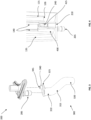
- FIGS 1 and 2 show respective top and bottom perspective views of a pulsation damper according to aspects of the invention.
- the pulsation damper 100 comprises a housing defining a fluid chamber 105.
- the housing is formed of an outlet wall 115 located at the top of the damper 100, an inlet wall 200 located at the bottom of the damper 100 and three side walls 110 in between the outlet wall 115 and inlet wall 200.
- the fluid chamber may include air.
- the inlet wall 200 includes a liquid inlet 205 in the form of a barbed male member configured to connect to a deformable conduit 300.
- the inlet wall 200 also includes an air inlet 210 extending from the inlet wall 200 into the fluid chamber 105 and terminates with a duck-billed valve 240.
- the outlet wall 115 is shown with a liquid outlet 120 in the form of a barbed male member.
- the liquid outlet 120 is configured to connect to a discharge pipe to discharge condensate liquid from a condensate pump system 500.
- the pulsation damper 100 is located downstream of the condensate pump system 500 and in close proximity to a pump motor (not shown) and is connected to a pump motor outlet 505 by the deformable conduit 300.
- the pulsation damper 100 receives liquid from the pump motor outlet 505 and dissipates the pulsation in the fluid chamber 105 before discharging the liquid through the liquid outlet 120 located in the outlet wall 115 of the fluid chamber 105. While a duck-billed valve 240 is shown in the Figures, it would be appreciated that other one-way valves compatible with the present damper would be included by this description.
- liquid inlet 205 and liquid outlet 120 are shown as barbed male members, it would be appreciated that other configurations of liquid inlet would be equally compatible with the present damper. While the liquid inlet 205 is formed as part of the inlet wall 200, this is not essential and the liquid inlet 205 may be formed in any of the walls of the housing 105. Similarly, the liquid outlet 120 may be formed in any of the walls of the housing 105.
- the inlet wall 200 is securely connected to the pump motor using a liquid inlet 205 configured as a barbed member extending from surface 215 away from the chamber 105.
- the liquid inlet 205 can be considered to form a liquid inlet channel that extends through the deformable conduit 300.
- the flexible conduit 300 receives the liquid inlet 205 and is secured by the barbed configuration of the liquid inlet 205.
- the inlet wall 200 is shown with air inlet 210.
- the deformable conduit 300 is configured to dissipate vibrations from the condensate pump 500.
- the deformable conduit 300 is preferably formed of three segments 310, 315, 320 which create a dog-legged configuration and is configured to receive the outlet of the pump motor 505. This is particularly advantageous as it allows the oscillations of the pump motor (not shown) to be absorbed by the deformable conduit 300 rather than transmitted to the pulsation damper system 100 and any surrounding pipework or casings, as would be the case with a straight and/or rigid conduit.
- the conduit 300 is more flexible in bending than it is in compression or torsion. However, more or fewer than three segments may be used to achieve this effect.
- the conduit 300 also comprises a connecting member 325 which extends laterally with respect to the axis of the inlet 205 and which includes an air inlet protrusion 340 extending parallel to but laterally offset from the inlet 205 axis.
- the protrusion 340 is received by the air inlet 210 of the inlet wall 200 and is shown including a bore 345 which extends through the air inlet protrusion 340 to provide a source of air to the pulsation damper 100.
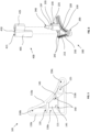
- the internal configuration of the fluid chamber is best shown in Figures 4 and 5 .
- the chamber walls 110, outlet wall 115 and inlet wall 200 define the internal volume of the fluid chamber 105.
- Dividing wall 135 creates an inner or central region 150a and an outer region 150b.
- a further outer region 150c is created by the walls of liquid outlet channel 125 extending into the chamber 105.
- the central region 150a contains a mix of air and liquid from the pump motor, whereas the outer regions 150b, 150c primarily contain air.
- the closest surface pulsations within the liquid could reflect off is the outlet wall 115, which is 48 mm away from the termination of the top surface 410 of the damper 400 in the arrangement illustrated.
- the fluid chamber 105 is held firmly in place against the inlet wall 200 by multiple mechanical engaging elements 245, 250.
- the mechanical elements include cantilever clips and a series protruding of elements designed to fit into corresponding grooves within the chamber side wall 110 (not shown).
- the force holding the chamber 105 against the inlet wall 200 also causes the lower face 145 of the dividing walls 140 to press down onto the upper surface 410 of the damper 400 which firmly holds the damper 400 against the inlet wall 200 which enhances the seals created between the inlet wall 200 and the damper 400 described in greater detail below.
- the inner surface 485 has a taper angle of 7 degrees, narrowing downstream or in the direction of liquid flow, and the liquid channel outlet 415 has an internal diameter of 3.5 mm. This combination is found to be particularly effective at damping the pulsations caused by condensate pumps used in air conditioning and refrigeration systems. However, configurations with larger or smaller diameters that incorporate the taper angle of 7 degrees will also benefit from the reduction in pulsation.
- the liquid outlet channel 125 extends into the chamber 105 such that the outlet port 126 of the outlet channel 125 within the chamber 105 is located below the upper surface 410 of the damper 400.
- the upper surface 410 of the damper 400 is offset by 21 mm from the bottom surface 215 and the inlet port 126 of the liquid outlet channel 125 of the chamber fluid outlet is offset 13.5 mm from the bottom surface 215.
- a continuous liquid channel is formed by the deformable conduit 300 and the liquid dampening channel 405 of the damper element 400. By terminating the liquid inlet channel 405 above the inlet of the liquid outlet channel 125, it is possible to direct liquid entering the chamber 105 towards the first air pocket.
- Arranging the liquid inlet 205 and outlet 125 in the offset manner described above ensures the fluid flow path between the liquid inlet 205 and liquid outlet 125 is not a straight line and that the hydraulic continuity of the liquid entering the chamber 105 is broken. This causes any pulsations remaining in the liquid to be dampened, substantially reducing any vibrations within the liquid being transmitted downstream. While the liquid outlet channel 125 may pass through the air pocket, the inlet port 126 of the liquid outlet 125 must remain outside the air pocket so that the damper 100 can function.
- the first and second air pockets are intended to remain in the chamber throughout the life of the vibration damper 100. This is achieved by the arrangement of the internal components within the chamber 105. However, in some instances it may be necessary to replenish either or both of the first and second air pockets.
- air inlet 210 While the air inlet 210 will replenish the air pockets during normal operation, when there is a high pressure head within the chamber 105, the air inlet may remain shut due to the pressure within the chamber 105 being greater than ambient.
- air can be introduced into the chamber 105 by controlling the condensate pump 500 such that the liquid level within the condensate reservoir 515 (see Figure 10 ) of the condensate pump 500 is lowered below the level of the pump motor inlet (not shown) of the condensate pump 500. This would cause air to be drawn into the chamber 105 and replenish the air pockets.
- this function may be controlled by a timer on board the microprocessor within the condensate pump to ensure the pump motor is only introducing air for the minimum period of time required to replenish the air pockets.
- a reciprocating motor In operation, a reciprocating motor generates cycles of positive and negative pressure gradients at the motor outlet, which can cause liquid to be drawn back upstream, which may cause some of the liquid to leak out of the housing 105.
- the present pulsation damper 100 incorporates multiple mechanical features to prevent back flow of liquid out of the inlet wall 200.
- a collar 220 extending from the base 215 is received by a corresponding recess 455 in the liquid channel 405.
- the collar 220 has outer and upper surfaces which engage with the inner surface 457 of the recess 455 and surface 460 around the liquid inlet 450.
- Air is introduced to the chamber 105 through air inlet 210 in the inlet wall 200 which passes through air inlet extrusion 225 extending from the base 215 in an inward direction.
- a bore (not shown) extends through the length of the air inlet extrusion 225 from the top surface 230 to the air inlet 210 and is configured to receive the shoulder 235 of the duck-billed valve 240.
- the duck-billed valve 240 is also received by a first opening 465 of the air channel 425 of the damper element 400.
- the air inlet 210 is used to replenish the trapped air pocket within the chamber 105, as some of the trapped air may be discharged with the liquid being pumped out of the chamber 105.
- air inlet 210 is shown separate to the liquid inlet 205, it would be possible to incorporate the air inlet 210 into the liquid inlet 205. Similarly, it would be possible to introduce air into the liquid passing through the deformable conduit 300. Where air is introduced into the liquid entering the fluid chamber, it would be understood that air mixed with liquid would be introduced into the fluid chamber, which would be equally effective at providing and maintaining the first air pocket within the fluid chamber.
- Liquid is prevented from flowing back through the damper air channel 425 by a series of seals.
- the shoulder 235 of the duck-billed valve 240 is secured by a press fit within the bore of the air inlet extrusion 225.
- the surface 237 connecting the duck-billed valve 240 to its shoulder 235 engages with the inner surface 467 of the air channel 425 to form a seal.
- the top surface of the shoulder 235 engages with the lower surface 470 of the air channel 425 to provide a final seal.
- the duck-billed valve 240 is arranged such that the weight of water over the valve will cause the valve to press shut.
- the duck-billed valve 240 has the added functionality of acting as an anti-siphoning device. This alleviates the need to have a separate anti-siphoning device located along the discharge line, as is typically the case in such systems.
- the siphoning effect occurs when the liquid outlet of the system is located below the height of the pump motor. In this case the liquid downstream of the pump generates a pressure head across the non-return valve of the pump motor. As the non-return valve only requires minimal pressure to open, the weight of the liquid retained in the condensate pump motor is sufficient to cause some seepage through the non-return valve.
- an anti-siphoning device typically an air valve, can be incorporated downstream of the pump motor. This allows the outlet of the discharge line to be located lower than the pump motor, as the anti-siphoning device will open and prevent any pressure head from building up due to the liquid retained in the discharge line downstream of the pump.
- the negative pressure gradient caused by the pressure head in the discharge line causes the duck-billed valve 240 to open and neutralise the pressure head, preventing the pump motor from being siphoned "dry” and therefore prolonging the life of the motor.
- the air inlet protrusion 340 has been further designed to reduce the "slapping" sound typical of anti-siphoning devices. This is achieved by incorporating a flap valve 350 in the bore 345 of the air inlet protrusion 340, as shown in Figure 9 .
- the flap valve 350 is designed to substantially reduce the level of noise escaping the bore 345 of the air inlet protrusion 340, while still allowing sufficient air to reach the air outlet valve 240 and enter the air channel 425.
- the protrusion 340 is connected to the air inlet 210, the air inlet 210 is extended away from the external surface of the housing 105.
- the flap 350 is located in the air inlet 210, which is the preferred arrangement of the present system.
- the fluid chamber 105 has also been designed to fit within the corner of a vertical section of trunking.
- the casing 510 used to contain the condensate pump 500 is shown with the front cover removed for clarity. Once installed, the vertical section of trunking would attach to the casing 510 and the condensate pump 500 and pulsation damper 100 would not be visible.
- This layout uses the existing space around the trunking without compromising the area needed to install the remaining piping of a refrigeration or air conditioning system.
- the curved side wall 110A of the fluid chamber 105 is one such feature that enables the pulsation dampener 100 of the present invention to occupy minimal space as possible while providing the necessary damping effect. This is also achieved by the chamfered faces of the damper element 400 which have been designed to conform with the geometry of the air inlet extrusion 225, the liquid outlet channel 125 and the curvature of the housing walls 110A.
- the present system is designed such that the pulsation dampener system can be installed to the left or right of a high wall split system. This further enhances the flexibility of the present system over existing dampener systems.
- the deformable conduit 300 has been designed to provide a swept angle using the three segments 310, 315, 320, as this allows the system to be installed in left- or right-handed corners of trunking with the same part without any orientation change or additional rotations.
- the pulsation damper 100 is configured such that it can be installed with condensate pumps 500 in a right-handed corner (as shown in Figure 10 ) or a left-handed corner (the mirror of what is shown in Figure 10 , with the condensate pump 500 arranged in an 'L' configuration instead of a backward 'L')
Landscapes
- Engineering & Computer Science (AREA)
- General Engineering & Computer Science (AREA)
- Mechanical Engineering (AREA)
- Reciprocating Pumps (AREA)
- Details Of Reciprocating Pumps (AREA)
- Pipe Accessories (AREA)
Description
- This invention relates to a pulsation damper, in particular but not exclusively, a pulsation damper for dampening pulsations in fluids flowing within reciprocating pump systems.
- Condensate pumping systems will typically vibrate during operation. This is due to movements of a pump motor (typically a reciprocating piston pump, the reciprocating action of which generates pressure waves at the motor outlet). These pressure waves travel down a discharge pipe and cause high frequency oscillations of the discharge pipe. Aside from mechanical wear and damage of any equipment connected to or near the discharge pipe, the oscillations in the discharge pipe can cause significant noise to be produced as it rattles against equipment in contact with the discharge pipe. Casings or housings for the discharge pipe can act as an amplifier of noise, which is undesirable, particularly in systems that are intended for indoor use.
- One solution to this problem is to apply a pulsation damper. Pulsation dampers typically use a compressible bladder or diaphragm to dissipate the pressure waves generated by the pump motor outlet. Alternative arrangements known in the art include dispersion systems that use a series of walls to disperse the pressure wave to create a smooth liquid flow. However, such prior art systems are complicated to manufacture and require additional equipment, such as compressed air cylinders in the case of bladder pulsation dampeners, to operate.
- Such equipment can also take up considerable space which is particularly undesirable if a pulsation damper is to be used with an indoor system, such as an air conditioner or refrigerator, where space may be at a premium. Indoor systems that require condensate pumps to pump liquid to enable the respective systems to operate need to operate discretely and with minimal additional equipment due to space constraints. Typically, a pulsation damper is located as close as possible to the source of vibrations in a system. In the case of air conditioning or refrigeration systems, this will be the condensate pump. As such, the pulsation damper is located as close as possible to the condensate pump motor, which is not practical if additional equipment has to be installed next to an indoor air conditioning system. By dissipating pulsations in the liquid prior to discharging the liquid, vibrations in the discharge pipe due to the pulsations are largely eliminated. This makes for an easier installation of the condensate pumping system, as it is no longer essential to route the discharge pipe away from any adjacent equipment that the pipe might have rattled against.
US 2,905,200 discloses a pulsation damper for reducing the surge which is inherent in the discharge line of any reciprocating type pump.US 4,590,796 discloses fuel systems for liquid fuel engines and, in particular, to a technique for damping flow pulsations and measuring fuel flow in fuel systems for liquid fuel engines.US 2,256,370 discloses an automatic air chamber for use in the discharge line of reciprocating pumps as an attachment to a slush pump of the type used in the drilling of deep oil wells.CH 706444 EP 0561502 discloses a fuel pressure pulsation dampener valve with a housing with an internal chamber into which inlet and outlet tubes communicate to transfer fuel under pressure to the fuel injectors of an internal combustion engine.US 4,514,151 discloses a liquid pulsation dampener device for use in a piping network, including at least one hydropneumatic vibration dampener arranged at the delivery side of a positive-displacement pump. - The described embodiments of the present invention seek to address these problems.
- Viewed from a first aspect, the present invention provides a pulsation damper for a condensate pump comprising a housing defining a fluid chamber having a liquid inlet connectable to an outlet of the condensate pump, an air inlet, and a liquid outlet and a damper element connected to the liquid inlet and projecting into the fluid chamber, forming a pulsation dampening channel, wherein the air inlet includes a one-way valve configured to selectively introduce air into the housing to maintain a first air pocket within the fluid chamber as liquid flows through the fluid chamber from the liquid inlet to the liquid outlet, wherein the liquid outlet is located outside the first air pocket, and wherein the air pocket is configured to dissipate pulsations within liquid entering the housing at the liquid inlet prior to the liquid discharging via the liquid outlet. This creates a pulsation damper that has no moving parts, which is considerably easier to manufacture and maintain compared to existing systems which incorporate bladders or diaphragms.
- The pulsation damper may comprise at least one dividing wall protruding from an inner surface of the housing defining a first region and a second region within the fluid chamber.
- The first region may contain a mix of liquid and the first air pocket. The liquid inlet may be located within the first region. Where a second region is present in the fluid chamber, the second region may contain a second air pocket. By creating a second air pocket, the present damper is able to remain effective, even if air from the first air pocket is removed during operation. This may occur in flow systems with high pressure heads.
- The wall of the liquid outlet may form a portion of the dividing wall.
- The pulsation dampening channel may have a tapered internal profile where the internal profile tapers in the direction of the liquid flow. The tapered internal profile may have a taper angle of 7-degrees. By incorporating a tapered internal profile, the present damper is able to reduce the pulsations in the fluid as the fluid enters the fluid chamber, further increasing the effectiveness of the damper.
- The damper element may be connected to the air inlet, whereby to form an air inlet channel extending into the fluid chamber.
- The pulsation damper may comprise a deformable conduit connected to the liquid inlet. The deformable conduit is configured to dissipate vibrations from the condensate pump. The deformable conduit is formed of a first flexible body segment having a first longitudinal axis and a second flexible body segment having a second longitudinal axis. The first and second longitudinal axes may be noncolinear. The liquid inlet of the inlet wall may be a barbed structure. Inclusion of a deformable conduit at the liquid inlet provides an additional layer of anti-vibration dampening, as vibrations in the pump motor will not be transmitted down the discharge line and cause rattling of the discharge line against surrounding equipment. The design of the deformable conduit is such that it absorbs vibrations from the pump motor before they reach the fluid chamber.
- The deformable conduit may comprise a connecting member having a protrusion connected to the air inlet, whereby to extend the air inlet channel away from an external surface of the housing. The protrusion may contain a flap valve located within the air inlet channel of the protrusion. This is advantageous, as the flap valve has been developed to reduce the sound created when air is introduced via the one-way valve.
- The liquid inlet may be offset from the liquid outlet. The liquid inlet may terminate above the liquid outlet. This offset configuration provides a further dissipation mechanism within the fluid chamber, as the fluid flow path from the liquid inlet to the liquid outlet is not a straight line, which would have allowed some of the pulsations to be discharged from the damper.
- The one-way valve may be a duck-billed valve.
- An inlet wall may be secured to the chamber housing by a series of mechanical fastenings. The mechanical fastenings may be any of interleaving protrusions or cantilevered connections between the inlet wall and housing walls.
- Embodiments of the invention are further described hereinafter with reference to the accompanying drawings, in which:
-
Figures 1 and 2 show respective top and bottom perspective views of a pulsation damper according to aspects of the invention; -
Figure 3 shows an exploded view of an inlet wall member and deformable conduit of the pulsation damper; -
Figure 4 is a cross-sectional view showing internal components of the pulsation damper; -
Figure 5 shows an underside section view of a fluid chamber of the pulsation damper; -
Figure 6 shows an exploded view of the inlet wall member and an associated damper; -
Figure 7 shows an underside perspective view of the damper; -
Figure 8 shows a side section view of the damper; -
Figure 9 shows a side section view of a portion of the deformable conduit; -
Figure 10 shows an exploded view of the pulsation damper and condensate pump. - The present invention seeks to provide a pulsation damper which requires minimal installation and maintenance effort while reducing the vibrations in a discharge line downstream of a reciprocating pump motor. The present invention achieves this by trapping a pocket of air within a fluid chamber. Deliberately incorporating a small amount of air in the fluid chamber causes the liquid to effectively become compressible within the chamber, which allows the air to absorb the pressure pulses before the liquid is discharged as a smooth liquid flow. This is significantly advantageous over prior art systems, as there is no need for compressed air equipment or a complicated series of deflector walls within the chamber. This enables the present pulsation dampener to be used in confined spaces and installed with minimal effort.
-
Figures 1 and 2 show respective top and bottom perspective views of a pulsation damper according to aspects of the invention. Thepulsation damper 100 comprises a housing defining afluid chamber 105. As shown in the Figures, the housing is formed of anoutlet wall 115 located at the top of thedamper 100, aninlet wall 200 located at the bottom of thedamper 100 and threeside walls 110 in between theoutlet wall 115 andinlet wall 200. It should be noted that although a fluid chamber is referred to, it would be clear that the fluid chamber may include air. - As shown in
Figures 1 and 2 and with reference toFigures 5 and10 , one of theside walls 110a is concavely curved and the two other side walls 11 0b, 110c are straight.Side walls curved side wall 110a. Theinlet wall 200 includes aliquid inlet 205 in the form of a barbed male member configured to connect to adeformable conduit 300. Theinlet wall 200 also includes anair inlet 210 extending from theinlet wall 200 into thefluid chamber 105 and terminates with a duck-billedvalve 240. Theoutlet wall 115 is shown with aliquid outlet 120 in the form of a barbed male member. Theliquid outlet 120 is configured to connect to a discharge pipe to discharge condensate liquid from acondensate pump system 500. Thepulsation damper 100 is located downstream of thecondensate pump system 500 and in close proximity to a pump motor (not shown) and is connected to apump motor outlet 505 by thedeformable conduit 300. Thepulsation damper 100 receives liquid from thepump motor outlet 505 and dissipates the pulsation in thefluid chamber 105 before discharging the liquid through theliquid outlet 120 located in theoutlet wall 115 of thefluid chamber 105. While a duck-billedvalve 240 is shown in the Figures, it would be appreciated that other one-way valves compatible with the present damper would be included by this description. While theliquid inlet 205 andliquid outlet 120 are shown as barbed male members, it would be appreciated that other configurations of liquid inlet would be equally compatible with the present damper. While theliquid inlet 205 is formed as part of theinlet wall 200, this is not essential and theliquid inlet 205 may be formed in any of the walls of thehousing 105. Similarly, theliquid outlet 120 may be formed in any of the walls of thehousing 105. - As shown in
Figure 3 , theinlet wall 200 is securely connected to the pump motor using aliquid inlet 205 configured as a barbed member extending fromsurface 215 away from thechamber 105. Theliquid inlet 205 can be considered to form a liquid inlet channel that extends through thedeformable conduit 300. Theflexible conduit 300 receives theliquid inlet 205 and is secured by the barbed configuration of theliquid inlet 205. Theinlet wall 200 is shown withair inlet 210. - As best shown in
Figure 3 and with reference toFigure 10 , thedeformable conduit 300 is configured to dissipate vibrations from thecondensate pump 500. Thedeformable conduit 300 is preferably formed of threesegments pump motor 505. This is particularly advantageous as it allows the oscillations of the pump motor (not shown) to be absorbed by thedeformable conduit 300 rather than transmitted to thepulsation damper system 100 and any surrounding pipework or casings, as would be the case with a straight and/or rigid conduit. To enhance this effect, theconduit 300 is more flexible in bending than it is in compression or torsion. However, more or fewer than three segments may be used to achieve this effect. Theconduit 300 also comprises a connectingmember 325 which extends laterally with respect to the axis of theinlet 205 and which includes anair inlet protrusion 340 extending parallel to but laterally offset from theinlet 205 axis. Theprotrusion 340 is received by theair inlet 210 of theinlet wall 200 and is shown including abore 345 which extends through theair inlet protrusion 340 to provide a source of air to thepulsation damper 100. - The internal configuration of the fluid chamber is best shown in
Figures 4 and5 . Thechamber walls 110,outlet wall 115 andinlet wall 200 define the internal volume of thefluid chamber 105. Dividingwall 135 creates an inner orcentral region 150a and anouter region 150b. A furtherouter region 150c is created by the walls ofliquid outlet channel 125 extending into thechamber 105. Thecentral region 150a contains a mix of air and liquid from the pump motor, whereas theouter regions outlet wall 115, which is 48 mm away from the termination of thetop surface 410 of thedamper 400 in the arrangement illustrated. There is a chance that air from thecentral region 150a will be displaced and lost through theliquid outlet channel 125 which would reduce the effectiveness of thedamper 100. High pressure heads in the system may exacerbate this problem. To account for this, the greater volume of air in theouter regions - As shown in
Figures 4 and6 , thefluid chamber 105 is held firmly in place against theinlet wall 200 by multiple mechanicalengaging elements inlet wall 200 is held securely against thefluid chamber 105 and prevents liquid contained within thechamber 105 from seeping or leaking out. The mechanical elements include cantilever clips and a series protruding of elements designed to fit into corresponding grooves within the chamber side wall 110 (not shown). The force holding thechamber 105 against theinlet wall 200 also causes thelower face 145 of the dividingwalls 140 to press down onto theupper surface 410 of thedamper 400 which firmly holds thedamper 400 against theinlet wall 200 which enhances the seals created between theinlet wall 200 and thedamper 400 described in greater detail below. - The features of the present invention that provide the damping effect are best illustrated in
Figures 4 to 8 . Liquid is introduced into thechamber 105 via thepulsation dampening channel 405 of thedamper element 400. As liquid is pumped from theliquid inlet 205 of theinlet wall 200 through the dampeningchannel 405 of thedamper 400, the trapped air bubble within the fluid chamber compresses and absorbs the incoming pulsation and reduces the pressure perturbations in the discharge line. As can be seen inFigure 8 the dampeningchannel 405 has a taperedinternal surface 485. This taperedinternal surface 485 is configured specifically to aid the damping effect of the present system. As shown, the dampeningchannel 405 approximates a conical frustum. Theinner surface 485 has a taper angle of 7 degrees, narrowing downstream or in the direction of liquid flow, and theliquid channel outlet 415 has an internal diameter of 3.5 mm. This combination is found to be particularly effective at damping the pulsations caused by condensate pumps used in air conditioning and refrigeration systems. However, configurations with larger or smaller diameters that incorporate the taper angle of 7 degrees will also benefit from the reduction in pulsation. Theliquid outlet channel 125 extends into thechamber 105 such that theoutlet port 126 of theoutlet channel 125 within thechamber 105 is located below theupper surface 410 of thedamper 400. As shown, theupper surface 410 of thedamper 400 is offset by 21 mm from thebottom surface 215 and theinlet port 126 of theliquid outlet channel 125 of the chamber fluid outlet is offset 13.5 mm from thebottom surface 215. This sets the initial water level in thefluid chamber 105, but during operation the water level will be dependent on the pressure head within thechamber 105. When thedamper element 400 is fitted to theinlet wall 200, a continuous liquid channel is formed by thedeformable conduit 300 and theliquid dampening channel 405 of thedamper element 400. By terminating theliquid inlet channel 405 above the inlet of theliquid outlet channel 125, it is possible to direct liquid entering thechamber 105 towards the first air pocket. Arranging theliquid inlet 205 andoutlet 125 in the offset manner described above ensures the fluid flow path between theliquid inlet 205 andliquid outlet 125 is not a straight line and that the hydraulic continuity of the liquid entering thechamber 105 is broken. This causes any pulsations remaining in the liquid to be dampened, substantially reducing any vibrations within the liquid being transmitted downstream. While theliquid outlet channel 125 may pass through the air pocket, theinlet port 126 of theliquid outlet 125 must remain outside the air pocket so that thedamper 100 can function. The first and second air pockets are intended to remain in the chamber throughout the life of thevibration damper 100. This is achieved by the arrangement of the internal components within thechamber 105. However, in some instances it may be necessary to replenish either or both of the first and second air pockets. While theair inlet 210 will replenish the air pockets during normal operation, when there is a high pressure head within thechamber 105, the air inlet may remain shut due to the pressure within thechamber 105 being greater than ambient. In this case, air can be introduced into thechamber 105 by controlling thecondensate pump 500 such that the liquid level within the condensate reservoir 515 (seeFigure 10 ) of thecondensate pump 500 is lowered below the level of the pump motor inlet (not shown) of thecondensate pump 500. This would cause air to be drawn into thechamber 105 and replenish the air pockets. As starting the pump motor from a 'dry' state is undesirable, this function may be controlled by a timer on board the microprocessor within the condensate pump to ensure the pump motor is only introducing air for the minimum period of time required to replenish the air pockets. - In operation, a reciprocating motor generates cycles of positive and negative pressure gradients at the motor outlet, which can cause liquid to be drawn back upstream, which may cause some of the liquid to leak out of the
housing 105. Thepresent pulsation damper 100 incorporates multiple mechanical features to prevent back flow of liquid out of theinlet wall 200. Acollar 220 extending from thebase 215 is received by acorresponding recess 455 in theliquid channel 405. Thecollar 220 has outer and upper surfaces which engage with theinner surface 457 of therecess 455 andsurface 460 around theliquid inlet 450. By holding theinlet wall 200 securely against thechamber 105, these surfaces remain firmly in contact, creating a seal preventing the back flow of liquid out of theinlet wall 200. - Air is introduced to the
chamber 105 throughair inlet 210 in theinlet wall 200 which passes throughair inlet extrusion 225 extending from the base 215 in an inward direction. A bore (not shown) extends through the length of theair inlet extrusion 225 from thetop surface 230 to theair inlet 210 and is configured to receive theshoulder 235 of the duck-billedvalve 240. The duck-billedvalve 240 is also received by afirst opening 465 of theair channel 425 of thedamper element 400. Theair inlet 210 is used to replenish the trapped air pocket within thechamber 105, as some of the trapped air may be discharged with the liquid being pumped out of thechamber 105. While theair inlet 210 is shown separate to theliquid inlet 205, it would be possible to incorporate theair inlet 210 into theliquid inlet 205. Similarly, it would be possible to introduce air into the liquid passing through thedeformable conduit 300. Where air is introduced into the liquid entering the fluid chamber, it would be understood that air mixed with liquid would be introduced into the fluid chamber, which would be equally effective at providing and maintaining the first air pocket within the fluid chamber. - Liquid is prevented from flowing back through the
damper air channel 425 by a series of seals. Firstly, theshoulder 235 of the duck-billedvalve 240 is secured by a press fit within the bore of theair inlet extrusion 225. Secondly, thesurface 237 connecting the duck-billedvalve 240 to itsshoulder 235 engages with theinner surface 467 of theair channel 425 to form a seal. Thirdly, the top surface of theshoulder 235 engages with thelower surface 470 of theair channel 425 to provide a final seal. Finally, the duck-billedvalve 240 is arranged such that the weight of water over the valve will cause the valve to press shut. These features work in combination to prevent liquid leaking back through theair channel 425. The pressure exerted by the dividingwalls 140 onto thedamper 400 enhances the seals created in theair channel 425. - Aside from the pulsation dampening effects described above, the duck-billed
valve 240 has the added functionality of acting as an anti-siphoning device. This alleviates the need to have a separate anti-siphoning device located along the discharge line, as is typically the case in such systems. The siphoning effect occurs when the liquid outlet of the system is located below the height of the pump motor. In this case the liquid downstream of the pump generates a pressure head across the non-return valve of the pump motor. As the non-return valve only requires minimal pressure to open, the weight of the liquid retained in the condensate pump motor is sufficient to cause some seepage through the non-return valve. Eventually, this can result in the internal chamber of the pump motor becoming dry as all of the liquid is siphoned through the valve. If this happens, the pump motor may start up "dry" which can generate significant noise and wear of the internal components. To avoid this, an anti-siphoning device, typically an air valve, can be incorporated downstream of the pump motor. This allows the outlet of the discharge line to be located lower than the pump motor, as the anti-siphoning device will open and prevent any pressure head from building up due to the liquid retained in the discharge line downstream of the pump. The negative pressure gradient caused by the pressure head in the discharge line causes the duck-billedvalve 240 to open and neutralise the pressure head, preventing the pump motor from being siphoned "dry" and therefore prolonging the life of the motor. - In addition to the duck-billed
valve 240 acting as an anti-siphoning device, theair inlet protrusion 340 has been further designed to reduce the "slapping" sound typical of anti-siphoning devices. This is achieved by incorporating aflap valve 350 in thebore 345 of theair inlet protrusion 340, as shown inFigure 9 . Theflap valve 350 is designed to substantially reduce the level of noise escaping thebore 345 of theair inlet protrusion 340, while still allowing sufficient air to reach theair outlet valve 240 and enter theair channel 425. When theprotrusion 340 is connected to theair inlet 210, theair inlet 210 is extended away from the external surface of thehousing 105. When thepulsation damper 100 is assembled, theflap 350 is located in theair inlet 210, which is the preferred arrangement of the present system. - As shown in
Figure 10 , thefluid chamber 105 has also been designed to fit within the corner of a vertical section of trunking. Thecasing 510 used to contain thecondensate pump 500 is shown with the front cover removed for clarity. Once installed, the vertical section of trunking would attach to thecasing 510 and thecondensate pump 500 andpulsation damper 100 would not be visible. This layout uses the existing space around the trunking without compromising the area needed to install the remaining piping of a refrigeration or air conditioning system. The curved side wall 110A of thefluid chamber 105 is one such feature that enables thepulsation dampener 100 of the present invention to occupy minimal space as possible while providing the necessary damping effect. This is also achieved by the chamfered faces of thedamper element 400 which have been designed to conform with the geometry of theair inlet extrusion 225, theliquid outlet channel 125 and the curvature of the housing walls 110A. - In addition to occupying minimal space, the present system is designed such that the pulsation dampener system can be installed to the left or right of a high wall split system. This further enhances the flexibility of the present system over existing dampener systems. The
deformable conduit 300 has been designed to provide a swept angle using the threesegments pulsation damper 100 is configured such that it can be installed withcondensate pumps 500 in a right-handed corner (as shown inFigure 10 ) or a left-handed corner (the mirror of what is shown inFigure 10 , with thecondensate pump 500 arranged in an 'L' configuration instead of a backward 'L') - Throughout the description and claims of this specification, the words "comprise" and "contain" and variations of them mean "including but not limited to", and they are not intended to (and do not) exclude other moieties, additives, components, integers or steps. Throughout the description and claims of this specification, the singular encompasses the plural unless the context otherwise requires. In particular, where the indefinite article is used, the specification is to be understood as contemplating plurality as well as singularity, unless the context requires otherwise.
- Features, integers, characteristics, compounds, chemical moieties or groups described in conjunction with a particular aspect, embodiment or example of the invention are to be understood to be applicable to any other aspect, embodiment or example described herein unless incompatible therewith. All of the features disclosed in this specification (including any accompanying claims, abstract and drawings), and/or all of the steps of any method or process so disclosed, may be combined in any combination, except combinations where at least some of such features and/or steps are mutually exclusive. The invention is not restricted to the details of any foregoing embodiments.
Claims (15)
- A pulsation damper (100) for a condensate pump (500) comprising:a housing defining a fluid chamber (105) having a liquid inlet (205) connectable to an outlet (505) of the condensate pump (500), an air inlet (210), and a liquid outlet (120), anda damper element (400) connected to the liquid inlet (205) and projecting into the fluid chamber (105), forming a pulsation dampening channel (415),wherein the air inlet (210) includes a one-way valve (240) configured to selectively introduce air into the housing to maintain a first air pocket within the fluid chamber (105) as liquid flows through the fluid chamber (105) from the liquid inlet (205) to the liquid outlet (120),wherein the liquid outlet (120) is located outside the first air pocket,wherein the air pocket is configured to dissipate pulsations within liquid entering the housing at the liquid inlet (205) prior to the liquid discharging via the liquid outlet (120).
- A pulsation damper (100) according to claim 1, comprising at least one dividing wall (135, 140) protruding from an inner surface of the housing defining a first region (150a) and a second region (150b, 150c) within the fluid chamber (105), optionally wherein the first region (150a) contains a mix of liquid and the first air pocket.
- A pulsation damper (100) according to claim 2, wherein the liquid inlet (205) is within the first region (150a).
- A pulsation damper (100) according to claim 2 or 3, wherein the second region (150b, 150c) contains a second air pocket.
- A pulsation damper (100) according to any of claims 2 to 4, wherein the wall of the liquid outlet (120) forms a portion of the dividing wall (135, 140).
- A pulsation damper (100) according to any preceding claim, wherein the pulsation dampening channel (415) has a tapered internal profile (485), and wherein the tapered internal profile (485) tapers in the direction of the liquid flow.
- A pulsation damper (100) according to claim 6, wherein the pulsation dampening channel (415) has a 7-degree taper.
- A pulsation damper (100) according to any preceding claim, wherein the damper element (400) is connected to the air inlet (210), whereby to form an air inlet channel (425) extending into the fluid chamber (105).
- A pulsation damper (100) according to any preceding claim, comprising a deformable conduit (300) connected to the liquid inlet (205), wherein the deformable conduit (300) is configured to dissipate vibrations from the condensate pump (500).
- A pulsation damper (100) according to claim 9, wherein the deformable conduit (300) is formed of a first flexible body segment (310) having a first longitudinal axis and a second flexible body segment (315, 320) having a second longitudinal axis, and wherein the first and second longitudinal axes are noncolinear.
- A pulsation damper (100) according to any preceding claim, wherein the liquid inlet (205) is configured as a barbed structure.
- A pulsation damper (100) according to any of claims 9 to 11 when dependent on claim 9, wherein the deformable conduit (300) comprises a connecting member (325) having a protrusion (340) configured to connect to the air inlet (210) whereby to extend the air inlet channel (425) away from an external surface of the housing, optionally the pulsation damper (100) comprises a flap valve (350) located within the air inlet channel (425) of the protrusion (340).
- A pulsation damper (100) according to any preceding claim, wherein the liquid inlet (205) is offset from the liquid outlet (120), optionally wherein the liquid inlet (205) terminates above the liquid outlet (120).
- A pulsation damper (100) according to any preceding claim, wherein the one-way valve (240) is a duck-billed valve.
- A pulsation damper (100) according to any preceding claim, wherein an inlet wall (200) of the pulsation damper (100) is secured to the chamber housing by a series of mechanical fastenings (245, 250), optionally wherein the mechanical fastenings (245, 250) are any of interleaving protrusions or cantilevered connections between the inlet wall (200) and housing walls (110).
Applications Claiming Priority (2)
| Application Number | Priority Date | Filing Date | Title |
|---|---|---|---|
| GB1718626.3A GB2568285B (en) | 2017-11-10 | 2017-11-10 | Pulsation damper |
| PCT/GB2018/053095 WO2019092396A1 (en) | 2017-11-10 | 2018-10-25 | Pulsation damper |
Publications (2)
| Publication Number | Publication Date |
|---|---|
| EP3707377A1 EP3707377A1 (en) | 2020-09-16 |
| EP3707377B1 true EP3707377B1 (en) | 2023-02-15 |
Family
ID=60788306
Family Applications (1)
| Application Number | Title | Priority Date | Filing Date |
|---|---|---|---|
| EP18797051.2A Active EP3707377B1 (en) | 2017-11-10 | 2018-10-25 | Pulsation damper |
Country Status (6)
| Country | Link |
|---|---|
| US (1) | US11661930B2 (en) |
| EP (1) | EP3707377B1 (en) |
| CN (1) | CN111465766B (en) |
| AU (1) | AU2018363276B2 (en) |
| GB (1) | GB2568285B (en) |
| WO (1) | WO2019092396A1 (en) |
Families Citing this family (4)
| Publication number | Priority date | Publication date | Assignee | Title |
|---|---|---|---|---|
| GB2588052B (en) * | 2018-07-27 | 2023-03-29 | Aspen Pumps Ltd | Condensate pump assembly |
| GB2575973B (en) | 2018-07-27 | 2021-03-03 | Aspen Pumps Ltd | Condensate pump assembly |
| GB2589860A (en) * | 2019-12-09 | 2021-06-16 | Aspen Pumps Ltd | Pulsation damper |
| US11692537B2 (en) | 2021-01-11 | 2023-07-04 | Comet-ME Ltd. | Method and system for damping flow pulsation |
Family Cites Families (23)
| Publication number | Priority date | Publication date | Assignee | Title |
|---|---|---|---|---|
| US2256370A (en) * | 1940-02-15 | 1941-09-16 | Oil Well Supply Co | Automatic air chamber |
| US2636506A (en) * | 1951-04-11 | 1953-04-28 | Coe Mfg Co | Strainer-equipped condensation drainer |
| US2896862A (en) * | 1955-04-18 | 1959-07-28 | James A Bede | Accumulator |
| US2905200A (en) * | 1958-04-21 | 1959-09-22 | Nat Supply Co | Pulsation damper |
| US3889705A (en) * | 1973-08-30 | 1975-06-17 | Northrop Corp | Hydraulic system reservoir having separate oil and air-oil chambers |
| DE3044082C2 (en) * | 1980-11-24 | 1989-11-23 | Balcke-Dürr AG, 4030 Ratingen | Arrangement for damping liquid vibrations in a pipeline network |
| IT1179810B (en) * | 1984-10-31 | 1987-09-16 | Aspera Spa | HERMETIC MOTOR-COMPRESSOR GROUP FOR REFRIGERANT CIRCUITS |
| US4590796A (en) * | 1985-01-23 | 1986-05-27 | Floscan Instrument Co., Inc. | Apparatus and method for pulsation damping and flow measurement in liquid fuel system |
| US4929157A (en) * | 1987-11-23 | 1990-05-29 | Ford Motor Company | Pulsation damper for air conditioning compressor |
| GB8825767D0 (en) * | 1988-11-03 | 1988-12-07 | Rosewater Eng Ltd | Pump dampener |
| US5307782A (en) | 1992-03-16 | 1994-05-03 | Davco Manufacturing Corporation | Combined pressure wave suppressor, air/vapor purge and check valve |
| US5921261A (en) * | 1997-05-08 | 1999-07-13 | Eaton Corporation | Dampening resonance in a flow regulator |
| DE19808719C1 (en) * | 1998-03-02 | 1999-09-23 | Bosch Gmbh Robert | Tank for a motor vehicle and flange for such a tank |
| WO1999051909A1 (en) * | 1998-04-01 | 1999-10-14 | Aeroquip-Vickers International Gmbh | Device for reducing pulsations and/or vibrations in hydraulic hose line systems |
| JP3677447B2 (en) * | 2000-11-27 | 2005-08-03 | 松下冷機株式会社 | Hermetic compressor |
| US7469682B2 (en) * | 2004-12-01 | 2008-12-30 | Continental Automotive Systems Us, Inc. | Submersed fuel pressure regulator assembly |
| DE102006032098A1 (en) * | 2006-07-11 | 2008-01-24 | Siemens Ag | Device for collecting fuel in a fuel tank |
| FR2930314B1 (en) * | 2008-04-17 | 2011-05-13 | Charlatte Reservoirs | ANTI-BEAM HYDROPNEUMATIC RESERVOIR FOR HYDRAULIC PIPES WITH AN IMPROVED SHUTTER |
| BRPI1105162B1 (en) * | 2011-12-15 | 2021-08-24 | Embraco Indústria De Compressores E Soluções Em Refrigeração Ltda. | ACOUSTIC FILTER FOR ALTERNATIVE COMPRESSOR |
| CH706444A2 (en) * | 2012-04-27 | 2013-10-31 | Schlumpf Innovations Gmbh | Water pump system with hydraulic rams. |
| US9273813B2 (en) * | 2013-03-15 | 2016-03-01 | Lsp Products Group, Inc. | In-line water hammer arrester |
| US10100940B2 (en) * | 2016-06-14 | 2018-10-16 | Terumo Cardiovascular Systems Corporation | One-way valve devices |
| BR102016013787B1 (en) * | 2016-06-14 | 2022-05-17 | Embraco Indústria De Compressores E Soluções Em Refrigeração Ltda | Acoustic filter for compressor |
-
2017
- 2017-11-10 GB GB1718626.3A patent/GB2568285B/en active Active
-
2018
- 2018-10-25 AU AU2018363276A patent/AU2018363276B2/en not_active Ceased
- 2018-10-25 WO PCT/GB2018/053095 patent/WO2019092396A1/en not_active Ceased
- 2018-10-25 US US16/762,194 patent/US11661930B2/en active Active
- 2018-10-25 EP EP18797051.2A patent/EP3707377B1/en active Active
- 2018-10-25 CN CN201880079827.2A patent/CN111465766B/en not_active Expired - Fee Related
Also Published As
| Publication number | Publication date |
|---|---|
| AU2018363276B2 (en) | 2024-11-07 |
| GB2568285B (en) | 2020-07-08 |
| US11661930B2 (en) | 2023-05-30 |
| US20200362844A1 (en) | 2020-11-19 |
| WO2019092396A1 (en) | 2019-05-16 |
| CN111465766B (en) | 2022-09-02 |
| GB201718626D0 (en) | 2017-12-27 |
| CN111465766A (en) | 2020-07-28 |
| AU2018363276A1 (en) | 2020-05-28 |
| GB2568285A (en) | 2019-05-15 |
| EP3707377A1 (en) | 2020-09-16 |
Similar Documents
| Publication | Publication Date | Title |
|---|---|---|
| US11661930B2 (en) | Pulsation damper | |
| US8899940B2 (en) | Suction stabilizer for pump assembly | |
| AU2018390708B2 (en) | Pump | |
| KR101881678B1 (en) | High pressure pump | |
| US11913453B2 (en) | Slide valve for a twin-screw compressor | |
| EP3791069B1 (en) | Cellular tube for replacement of traditional gas-charged cartridges in suction stabilizers | |
| CN108571409A (en) | High pressure fuel pump for fuel injection system | |
| EP4073380B1 (en) | Pulsation damper | |
| JP5056838B2 (en) | Fluid coupling | |
| CN111512039A (en) | High-pressure fuel pump | |
| US8281817B2 (en) | Laminar flow tool | |
| RU2012124791A (en) | VISCOELASTIC COMPRESSOR PULSATION DAMPER | |
| KR102254868B1 (en) | Pulsation Reduction Device of Pump Using Air Damper | |
| RU2083908C1 (en) | Pressure stabilizer | |
| KR20220081726A (en) | Fuel pump module | |
| KR200169201Y1 (en) | Air chamber reducing pulsation of diaphragm pump | |
| FI120214B (en) | Arrangement for damping the vibration in a fuel feed system at a piston engine | |
| EA047392B1 (en) | REACTIVE FLUID SYSTEM THAT ACCOUNTS FOR THERMAL EXPANSION WHEN REPLACING NITROGEN INSIDE FILLED EQUIPMENT FOR PULSATION CONTROL | |
| KR20190011349A (en) | Pulsation pressure attenuator for braking apparatus | |
| US20210222813A1 (en) | Reactive fluid system accounting for thermal expansion in replacement of nitrogen within charged pulsation control equipment | |
| EA044798B1 (en) | MINI PUMP DAMPENERS COMBINED WITH A SYSTEM PULSATION DAMPER | |
| KR19990016941U (en) | Hydraulic pump of heavy duty vehicle | |
| EA043197B1 (en) | CELL TUBE FOR USE INSTEAD OF TRADITIONAL GAS FILLED CARTRIDGES IN SUCTION STABILIZERS |
Legal Events
| Date | Code | Title | Description |
|---|---|---|---|
| STAA | Information on the status of an ep patent application or granted ep patent |
Free format text: STATUS: UNKNOWN |
|
| STAA | Information on the status of an ep patent application or granted ep patent |
Free format text: STATUS: THE INTERNATIONAL PUBLICATION HAS BEEN MADE |
|
| PUAI | Public reference made under article 153(3) epc to a published international application that has entered the european phase |
Free format text: ORIGINAL CODE: 0009012 |
|
| STAA | Information on the status of an ep patent application or granted ep patent |
Free format text: STATUS: REQUEST FOR EXAMINATION WAS MADE |
|
| 17P | Request for examination filed |
Effective date: 20200519 |
|
| AK | Designated contracting states |
Kind code of ref document: A1 Designated state(s): AL AT BE BG CH CY CZ DE DK EE ES FI FR GB GR HR HU IE IS IT LI LT LU LV MC MK MT NL NO PL PT RO RS SE SI SK SM TR |
|
| AX | Request for extension of the european patent |
Extension state: BA ME |
|
| DAV | Request for validation of the european patent (deleted) | ||
| DAX | Request for extension of the european patent (deleted) | ||
| REG | Reference to a national code |
Ref country code: DE Ref legal event code: R079 Ref document number: 602018046197 Country of ref document: DE Free format text: PREVIOUS MAIN CLASS: F04B0011000000 Ipc: F04B0039000000 |
|
| RIC1 | Information provided on ipc code assigned before grant |
Ipc: F04B 11/00 20060101ALI20220901BHEP Ipc: F04B 39/00 20060101AFI20220901BHEP |
|
| GRAP | Despatch of communication of intention to grant a patent |
Free format text: ORIGINAL CODE: EPIDOSNIGR1 |
|
| STAA | Information on the status of an ep patent application or granted ep patent |
Free format text: STATUS: GRANT OF PATENT IS INTENDED |
|
| INTG | Intention to grant announced |
Effective date: 20221013 |
|
| GRAS | Grant fee paid |
Free format text: ORIGINAL CODE: EPIDOSNIGR3 |
|
| GRAA | (expected) grant |
Free format text: ORIGINAL CODE: 0009210 |
|
| STAA | Information on the status of an ep patent application or granted ep patent |
Free format text: STATUS: THE PATENT HAS BEEN GRANTED |
|
| AK | Designated contracting states |
Kind code of ref document: B1 Designated state(s): AL AT BE BG CH CY CZ DE DK EE ES FI FR GB GR HR HU IE IS IT LI LT LU LV MC MK MT NL NO PL PT RO RS SE SI SK SM TR |
|
| REG | Reference to a national code |
Ref country code: CH Ref legal event code: EP Ref country code: GB Ref legal event code: FG4D |
|
| REG | Reference to a national code |
Ref country code: DE Ref legal event code: R096 Ref document number: 602018046197 Country of ref document: DE |
|
| REG | Reference to a national code |
Ref country code: AT Ref legal event code: REF Ref document number: 1548361 Country of ref document: AT Kind code of ref document: T Effective date: 20230315 Ref country code: IE Ref legal event code: FG4D |
|
| REG | Reference to a national code |
Ref country code: LT Ref legal event code: MG9D |
|
| REG | Reference to a national code |
Ref country code: NL Ref legal event code: MP Effective date: 20230215 |
|
| REG | Reference to a national code |
Ref country code: AT Ref legal event code: MK05 Ref document number: 1548361 Country of ref document: AT Kind code of ref document: T Effective date: 20230215 |
|
| PG25 | Lapsed in a contracting state [announced via postgrant information from national office to epo] |
Ref country code: RS Free format text: LAPSE BECAUSE OF FAILURE TO SUBMIT A TRANSLATION OF THE DESCRIPTION OR TO PAY THE FEE WITHIN THE PRESCRIBED TIME-LIMIT Effective date: 20230215 Ref country code: PT Free format text: LAPSE BECAUSE OF FAILURE TO SUBMIT A TRANSLATION OF THE DESCRIPTION OR TO PAY THE FEE WITHIN THE PRESCRIBED TIME-LIMIT Effective date: 20230615 Ref country code: NO Free format text: LAPSE BECAUSE OF FAILURE TO SUBMIT A TRANSLATION OF THE DESCRIPTION OR TO PAY THE FEE WITHIN THE PRESCRIBED TIME-LIMIT Effective date: 20230515 Ref country code: NL Free format text: LAPSE BECAUSE OF FAILURE TO SUBMIT A TRANSLATION OF THE DESCRIPTION OR TO PAY THE FEE WITHIN THE PRESCRIBED TIME-LIMIT Effective date: 20230215 Ref country code: LV Free format text: LAPSE BECAUSE OF FAILURE TO SUBMIT A TRANSLATION OF THE DESCRIPTION OR TO PAY THE FEE WITHIN THE PRESCRIBED TIME-LIMIT Effective date: 20230215 Ref country code: LT Free format text: LAPSE BECAUSE OF FAILURE TO SUBMIT A TRANSLATION OF THE DESCRIPTION OR TO PAY THE FEE WITHIN THE PRESCRIBED TIME-LIMIT Effective date: 20230215 Ref country code: HR Free format text: LAPSE BECAUSE OF FAILURE TO SUBMIT A TRANSLATION OF THE DESCRIPTION OR TO PAY THE FEE WITHIN THE PRESCRIBED TIME-LIMIT Effective date: 20230215 Ref country code: ES Free format text: LAPSE BECAUSE OF FAILURE TO SUBMIT A TRANSLATION OF THE DESCRIPTION OR TO PAY THE FEE WITHIN THE PRESCRIBED TIME-LIMIT Effective date: 20230215 Ref country code: AT Free format text: LAPSE BECAUSE OF FAILURE TO SUBMIT A TRANSLATION OF THE DESCRIPTION OR TO PAY THE FEE WITHIN THE PRESCRIBED TIME-LIMIT Effective date: 20230215 |
|
| PG25 | Lapsed in a contracting state [announced via postgrant information from national office to epo] |
Ref country code: SE Free format text: LAPSE BECAUSE OF FAILURE TO SUBMIT A TRANSLATION OF THE DESCRIPTION OR TO PAY THE FEE WITHIN THE PRESCRIBED TIME-LIMIT Effective date: 20230215 Ref country code: PL Free format text: LAPSE BECAUSE OF FAILURE TO SUBMIT A TRANSLATION OF THE DESCRIPTION OR TO PAY THE FEE WITHIN THE PRESCRIBED TIME-LIMIT Effective date: 20230215 Ref country code: IS Free format text: LAPSE BECAUSE OF FAILURE TO SUBMIT A TRANSLATION OF THE DESCRIPTION OR TO PAY THE FEE WITHIN THE PRESCRIBED TIME-LIMIT Effective date: 20230615 Ref country code: GR Free format text: LAPSE BECAUSE OF FAILURE TO SUBMIT A TRANSLATION OF THE DESCRIPTION OR TO PAY THE FEE WITHIN THE PRESCRIBED TIME-LIMIT Effective date: 20230516 Ref country code: FI Free format text: LAPSE BECAUSE OF FAILURE TO SUBMIT A TRANSLATION OF THE DESCRIPTION OR TO PAY THE FEE WITHIN THE PRESCRIBED TIME-LIMIT Effective date: 20230215 |
|
| PG25 | Lapsed in a contracting state [announced via postgrant information from national office to epo] |
Ref country code: SM Free format text: LAPSE BECAUSE OF FAILURE TO SUBMIT A TRANSLATION OF THE DESCRIPTION OR TO PAY THE FEE WITHIN THE PRESCRIBED TIME-LIMIT Effective date: 20230215 Ref country code: RO Free format text: LAPSE BECAUSE OF FAILURE TO SUBMIT A TRANSLATION OF THE DESCRIPTION OR TO PAY THE FEE WITHIN THE PRESCRIBED TIME-LIMIT Effective date: 20230215 Ref country code: EE Free format text: LAPSE BECAUSE OF FAILURE TO SUBMIT A TRANSLATION OF THE DESCRIPTION OR TO PAY THE FEE WITHIN THE PRESCRIBED TIME-LIMIT Effective date: 20230215 Ref country code: DK Free format text: LAPSE BECAUSE OF FAILURE TO SUBMIT A TRANSLATION OF THE DESCRIPTION OR TO PAY THE FEE WITHIN THE PRESCRIBED TIME-LIMIT Effective date: 20230215 Ref country code: CZ Free format text: LAPSE BECAUSE OF FAILURE TO SUBMIT A TRANSLATION OF THE DESCRIPTION OR TO PAY THE FEE WITHIN THE PRESCRIBED TIME-LIMIT Effective date: 20230215 |
|
| REG | Reference to a national code |
Ref country code: DE Ref legal event code: R097 Ref document number: 602018046197 Country of ref document: DE |
|
| PG25 | Lapsed in a contracting state [announced via postgrant information from national office to epo] |
Ref country code: SK Free format text: LAPSE BECAUSE OF FAILURE TO SUBMIT A TRANSLATION OF THE DESCRIPTION OR TO PAY THE FEE WITHIN THE PRESCRIBED TIME-LIMIT Effective date: 20230215 |
|
| PLBE | No opposition filed within time limit |
Free format text: ORIGINAL CODE: 0009261 |
|
| STAA | Information on the status of an ep patent application or granted ep patent |
Free format text: STATUS: NO OPPOSITION FILED WITHIN TIME LIMIT |
|
| 26N | No opposition filed |
Effective date: 20231116 |
|
| PG25 | Lapsed in a contracting state [announced via postgrant information from national office to epo] |
Ref country code: SI Free format text: LAPSE BECAUSE OF FAILURE TO SUBMIT A TRANSLATION OF THE DESCRIPTION OR TO PAY THE FEE WITHIN THE PRESCRIBED TIME-LIMIT Effective date: 20230215 |
|
| PG25 | Lapsed in a contracting state [announced via postgrant information from national office to epo] |
Ref country code: IT Free format text: LAPSE BECAUSE OF FAILURE TO SUBMIT A TRANSLATION OF THE DESCRIPTION OR TO PAY THE FEE WITHIN THE PRESCRIBED TIME-LIMIT Effective date: 20230215 Ref country code: MC Free format text: LAPSE BECAUSE OF FAILURE TO SUBMIT A TRANSLATION OF THE DESCRIPTION OR TO PAY THE FEE WITHIN THE PRESCRIBED TIME-LIMIT Effective date: 20230215 |
|
| REG | Reference to a national code |
Ref country code: CH Ref legal event code: PL |
|
| REG | Reference to a national code |
Ref country code: BE Ref legal event code: MM Effective date: 20231031 |
|
| PG25 | Lapsed in a contracting state [announced via postgrant information from national office to epo] |
Ref country code: LU Free format text: LAPSE BECAUSE OF NON-PAYMENT OF DUE FEES Effective date: 20231025 |
|
| PG25 | Lapsed in a contracting state [announced via postgrant information from national office to epo] |
Ref country code: LU Free format text: LAPSE BECAUSE OF NON-PAYMENT OF DUE FEES Effective date: 20231025 |
|
| PG25 | Lapsed in a contracting state [announced via postgrant information from national office to epo] |
Ref country code: CH Free format text: LAPSE BECAUSE OF NON-PAYMENT OF DUE FEES Effective date: 20231031 |
|
| PG25 | Lapsed in a contracting state [announced via postgrant information from national office to epo] |
Ref country code: CH Free format text: LAPSE BECAUSE OF NON-PAYMENT OF DUE FEES Effective date: 20231031 |
|
| PG25 | Lapsed in a contracting state [announced via postgrant information from national office to epo] |
Ref country code: BE Free format text: LAPSE BECAUSE OF NON-PAYMENT OF DUE FEES Effective date: 20231031 |
|
| PG25 | Lapsed in a contracting state [announced via postgrant information from national office to epo] |
Ref country code: IE Free format text: LAPSE BECAUSE OF NON-PAYMENT OF DUE FEES Effective date: 20231025 |
|
| PG25 | Lapsed in a contracting state [announced via postgrant information from national office to epo] |
Ref country code: IE Free format text: LAPSE BECAUSE OF NON-PAYMENT OF DUE FEES Effective date: 20231025 |
|
| PG25 | Lapsed in a contracting state [announced via postgrant information from national office to epo] |
Ref country code: BG Free format text: LAPSE BECAUSE OF FAILURE TO SUBMIT A TRANSLATION OF THE DESCRIPTION OR TO PAY THE FEE WITHIN THE PRESCRIBED TIME-LIMIT Effective date: 20230215 |
|
| PG25 | Lapsed in a contracting state [announced via postgrant information from national office to epo] |
Ref country code: BG Free format text: LAPSE BECAUSE OF FAILURE TO SUBMIT A TRANSLATION OF THE DESCRIPTION OR TO PAY THE FEE WITHIN THE PRESCRIBED TIME-LIMIT Effective date: 20230215 |
|
| PG25 | Lapsed in a contracting state [announced via postgrant information from national office to epo] |
Ref country code: CY Free format text: LAPSE BECAUSE OF FAILURE TO SUBMIT A TRANSLATION OF THE DESCRIPTION OR TO PAY THE FEE WITHIN THE PRESCRIBED TIME-LIMIT; INVALID AB INITIO Effective date: 20181025 |
|
| PG25 | Lapsed in a contracting state [announced via postgrant information from national office to epo] |
Ref country code: HU Free format text: LAPSE BECAUSE OF FAILURE TO SUBMIT A TRANSLATION OF THE DESCRIPTION OR TO PAY THE FEE WITHIN THE PRESCRIBED TIME-LIMIT; INVALID AB INITIO Effective date: 20181025 |
|
| PGFP | Annual fee paid to national office [announced via postgrant information from national office to epo] |
Ref country code: GB Payment date: 20250924 Year of fee payment: 8 |
|
| PG25 | Lapsed in a contracting state [announced via postgrant information from national office to epo] |
Ref country code: TR Free format text: LAPSE BECAUSE OF FAILURE TO SUBMIT A TRANSLATION OF THE DESCRIPTION OR TO PAY THE FEE WITHIN THE PRESCRIBED TIME-LIMIT Effective date: 20230215 |
|
| PGFP | Annual fee paid to national office [announced via postgrant information from national office to epo] |
Ref country code: DE Payment date: 20251001 Year of fee payment: 8 |
|
| PGFP | Annual fee paid to national office [announced via postgrant information from national office to epo] |
Ref country code: FR Payment date: 20251003 Year of fee payment: 8 |