EP3707352B1 - Aktuatorsteuerungssystem für bistabile elektrische kipphebelverriegelungen - Google Patents
Aktuatorsteuerungssystem für bistabile elektrische kipphebelverriegelungen Download PDFInfo
- Publication number
- EP3707352B1 EP3707352B1 EP18796660.1A EP18796660A EP3707352B1 EP 3707352 B1 EP3707352 B1 EP 3707352B1 EP 18796660 A EP18796660 A EP 18796660A EP 3707352 B1 EP3707352 B1 EP 3707352B1
- Authority
- EP
- European Patent Office
- Prior art keywords
- rocker arm
- current
- valvetrain
- electromagnets
- electromagnet
- Prior art date
- Legal status (The legal status is an assumption and is not a legal conclusion. Google has not performed a legal analysis and makes no representation as to the accuracy of the status listed.)
- Active
Links
Images



Classifications
-
- F—MECHANICAL ENGINEERING; LIGHTING; HEATING; WEAPONS; BLASTING
- F01—MACHINES OR ENGINES IN GENERAL; ENGINE PLANTS IN GENERAL; STEAM ENGINES
- F01L—CYCLICALLY OPERATING VALVES FOR MACHINES OR ENGINES
- F01L9/00—Valve-gear or valve arrangements actuated non-mechanically
- F01L9/20—Valve-gear or valve arrangements actuated non-mechanically by electric means
- F01L9/21—Valve-gear or valve arrangements actuated non-mechanically by electric means actuated by solenoids
-
- F—MECHANICAL ENGINEERING; LIGHTING; HEATING; WEAPONS; BLASTING
- F01—MACHINES OR ENGINES IN GENERAL; ENGINE PLANTS IN GENERAL; STEAM ENGINES
- F01L—CYCLICALLY OPERATING VALVES FOR MACHINES OR ENGINES
- F01L1/00—Valve-gear or valve arrangements, e.g. lift-valve gear
- F01L1/12—Transmitting gear between valve drive and valve
- F01L1/18—Rocking arms or levers
- F01L1/185—Overhead end-pivot rocking arms
-
- F—MECHANICAL ENGINEERING; LIGHTING; HEATING; WEAPONS; BLASTING
- F01—MACHINES OR ENGINES IN GENERAL; ENGINE PLANTS IN GENERAL; STEAM ENGINES
- F01L—CYCLICALLY OPERATING VALVES FOR MACHINES OR ENGINES
- F01L9/00—Valve-gear or valve arrangements actuated non-mechanically
- F01L9/20—Valve-gear or valve arrangements actuated non-mechanically by electric means
- F01L9/26—Driving circuits therefor
-
- F—MECHANICAL ENGINEERING; LIGHTING; HEATING; WEAPONS; BLASTING
- F01—MACHINES OR ENGINES IN GENERAL; ENGINE PLANTS IN GENERAL; STEAM ENGINES
- F01L—CYCLICALLY OPERATING VALVES FOR MACHINES OR ENGINES
- F01L13/00—Modifications of valve-gear to facilitate reversing, braking, starting, changing compression ratio, or other specific operations
- F01L13/0005—Deactivating valves
-
- F—MECHANICAL ENGINEERING; LIGHTING; HEATING; WEAPONS; BLASTING
- F01—MACHINES OR ENGINES IN GENERAL; ENGINE PLANTS IN GENERAL; STEAM ENGINES
- F01L—CYCLICALLY OPERATING VALVES FOR MACHINES OR ENGINES
- F01L1/00—Valve-gear or valve arrangements, e.g. lift-valve gear
- F01L1/12—Transmitting gear between valve drive and valve
- F01L1/18—Rocking arms or levers
- F01L2001/186—Split rocking arms, e.g. rocker arms having two articulated parts and means for varying the relative position of these parts or for selectively connecting the parts to move in unison
-
- F—MECHANICAL ENGINEERING; LIGHTING; HEATING; WEAPONS; BLASTING
- F01—MACHINES OR ENGINES IN GENERAL; ENGINE PLANTS IN GENERAL; STEAM ENGINES
- F01L—CYCLICALLY OPERATING VALVES FOR MACHINES OR ENGINES
- F01L1/00—Valve-gear or valve arrangements, e.g. lift-valve gear
- F01L1/46—Component parts, details, or accessories, not provided for in preceding subgroups
- F01L2001/467—Lost motion springs
-
- F—MECHANICAL ENGINEERING; LIGHTING; HEATING; WEAPONS; BLASTING
- F01—MACHINES OR ENGINES IN GENERAL; ENGINE PLANTS IN GENERAL; STEAM ENGINES
- F01L—CYCLICALLY OPERATING VALVES FOR MACHINES OR ENGINES
- F01L9/00—Valve-gear or valve arrangements actuated non-mechanically
- F01L9/20—Valve-gear or valve arrangements actuated non-mechanically by electric means
- F01L9/21—Valve-gear or valve arrangements actuated non-mechanically by electric means actuated by solenoids
- F01L2009/2146—Latching means
- F01L2009/2148—Latching means using permanent magnet
-
- F—MECHANICAL ENGINEERING; LIGHTING; HEATING; WEAPONS; BLASTING
- F01—MACHINES OR ENGINES IN GENERAL; ENGINE PLANTS IN GENERAL; STEAM ENGINES
- F01L—CYCLICALLY OPERATING VALVES FOR MACHINES OR ENGINES
- F01L9/00—Valve-gear or valve arrangements actuated non-mechanically
- F01L9/20—Valve-gear or valve arrangements actuated non-mechanically by electric means
- F01L9/21—Valve-gear or valve arrangements actuated non-mechanically by electric means actuated by solenoids
- F01L2009/2161—Wiring
- F01L2009/2163—Connectors
-
- F—MECHANICAL ENGINEERING; LIGHTING; HEATING; WEAPONS; BLASTING
- F01—MACHINES OR ENGINES IN GENERAL; ENGINE PLANTS IN GENERAL; STEAM ENGINES
- F01L—CYCLICALLY OPERATING VALVES FOR MACHINES OR ENGINES
- F01L13/00—Modifications of valve-gear to facilitate reversing, braking, starting, changing compression ratio, or other specific operations
- F01L13/0005—Deactivating valves
- F01L2013/001—Deactivating cylinders
-
- F—MECHANICAL ENGINEERING; LIGHTING; HEATING; WEAPONS; BLASTING
- F01—MACHINES OR ENGINES IN GENERAL; ENGINE PLANTS IN GENERAL; STEAM ENGINES
- F01L—CYCLICALLY OPERATING VALVES FOR MACHINES OR ENGINES
- F01L2301/00—Using particular materials
-
- F—MECHANICAL ENGINEERING; LIGHTING; HEATING; WEAPONS; BLASTING
- F01—MACHINES OR ENGINES IN GENERAL; ENGINE PLANTS IN GENERAL; STEAM ENGINES
- F01L—CYCLICALLY OPERATING VALVES FOR MACHINES OR ENGINES
- F01L2305/00—Valve arrangements comprising rollers
-
- F—MECHANICAL ENGINEERING; LIGHTING; HEATING; WEAPONS; BLASTING
- F01—MACHINES OR ENGINES IN GENERAL; ENGINE PLANTS IN GENERAL; STEAM ENGINES
- F01L—CYCLICALLY OPERATING VALVES FOR MACHINES OR ENGINES
- F01L2800/00—Methods of operation using a variable valve timing mechanism
- F01L2800/08—Timing or lift different for valves of different cylinders
-
- F—MECHANICAL ENGINEERING; LIGHTING; HEATING; WEAPONS; BLASTING
- F01—MACHINES OR ENGINES IN GENERAL; ENGINE PLANTS IN GENERAL; STEAM ENGINES
- F01L—CYCLICALLY OPERATING VALVES FOR MACHINES OR ENGINES
- F01L2820/00—Details on specific features characterising valve gear arrangements
- F01L2820/03—Auxiliary actuators
- F01L2820/031—Electromagnets
Definitions
- valvetrains particularly valvetrains providing variable valve lift (VVL) or cylinder deactivation (CDA).
- VVL variable valve lift
- CDA cylinder deactivation
- Hydraulically actuated latches are used on some rocker arm assemblies to implement variable valve lift (VVL) or cylinder deactivation (CDA).
- VVL variable valve lift
- CDA cylinder deactivation
- SRFF switching roller finger followers
- pressurized oil from an oil pump may be used for latch actuation.
- OCV oil control valve
- ECU engine control unit
- a separate feed from the same source provides oil for hydraulic lash adjustment.
- each rocker arm assembly has two hydraulic feeds, which entails a degree of complexity and equipment cost. The oil demands of these hydraulic feeds may approach the limits of existing supply systems.
- Electromagnetic actuators latches require power.
- Rocker arms reciprocate rapidly over a prolonged period and in proximity to other moving parts. Wires attaching to a rocker arm could be caught, clipped, or fatigued and consequently short out.
- Attention is drawn to WO 2017 091 799 A1 which relates to a valvetrain for an internal combustion engine of the type that has a combustion chamber, a moveable valve having a seat formed in the combustion chamber, and a camshaft.
- the valve train includes a rocker arm assembly, a pivot providing a fulcrum for a rocker arm of the rocker arm assembly, and a latch assembly.
- An electrical device mounted to the rocker arm assembly receives power or communicates through a circuit that includes an electrical connection formed by abutment between surfaces of two distinct parts.
- the rocker arm assembly is operative to move one of the two abutting surfaces relative to the other in response to actuation of the cam follower.
- JP S 59 158 506 A relates to an electromagnet which can attract a movable core against the force of a recovering spring and a current control circuit which supply an electromagnet coil a pulse current whose polarity is changed in accordance with the operation of a switch.
- a permanent magnet which can attract a movable core against the expansion force of a recovering spring, is provided to a pole head of an electromagnet core.
- a main contact is closed, an auxiliary contact is opened and a charging current is applied to an electromagnet coil to charge a capacitor and the flux, whose direction is the same as that of the permanent magnet, is induced in the electromagnet core and the movable core is attracted by the permanent magnet.
- the charging current is gradually reduced according to the charge of the capacitor but the movable core is kept to be attracted even after the charging current becomes null.
- a valvetrain and a method as set forth in claims 1 and 8 are provided. Further embodiments are inter alia disclosed in the dependent claims.
- the present teachings relate to systems and methods for operating the valvetrain in an internal combustion engine of a type that has a combustion chamber, a moveable valve having a seat formed in the combustion chamber, a camshaft, and a rocker arm assembly that actuates the valve and includes and includes a rocker arm and a cam follower configured to engage a cam mounted on the camshaft as the camshaft rotates.
- the rocker arm assembly is configured such that rotation of the camshaft is operative to transmit force from the cam to the cam follower and move the rocker arm.
- the rocker arm assembly includes a latch pin translatable between a first position and a second position.
- One of the first and second latch pin positions provides a configuration in which the rocker arm assembly is operative to actuate the moveable valve in response to actuation of the cam follower by the cam to produce a first valve lift profile.
- the other of the first and second latch pin positions provides a configuration in which the rocker arm assembly is operative to actuate the moveable valve in response to actuation by the cam follower by the cam to produce a second valve lift profile, which is distinct from the first valve lift profile, or the moveable valve is deactivated.
- This structure may provide cylinder deactivation (CDA) or variable valve lift (VVL).
- the latch pin is part of an electromagnetic latch assembly that includes an electromagnet and in which the latch pin is stable independently from the electromagnet in both the first and the second positions.
- the latch pin is actuated from the first position to the second position by providing the electromagnet with a current in a first direction.
- the latch pin is actuated from the second position to the first position by providing the electromagnet with a current in a second direction, which is the reverse of the first.
- One or more permanent magnets may stabilize the latch pin in both the first and second positions.
- the electromagnet is mounted to a rocker arm of the rocker arm assembly.
- the electromagnet is powered through an electrical connection made by abutment between two distinct parts, one of which is mounted to the rocker arm. Movement of the rocker arm may cause relative motion between contacting surfaces of the abutting parts.
- an H-bridge would be used to provide DC current that is selectively either in a first direction or a second direction.
- An H-bridge would require connections to both terminals of the electromagnet.
- the present teachings recognize that it is possible to reduce the wire count and the number of couplings by grounding one terminal of the electromagnet and providing an actuator control system that connects to the other terminal to drive the electromagnet with a DC current that is selectively either in a forward or a reverse direction.
- one terminal of the electromagnet is grounded through the structure of the rocker arm assembly.
- the ground connection is made to a cylinder head of an engine.
- the actuator control system includes a DC/DC converter and switching elements.
- the DC/DC converter is coupled to the electromagnets through one or more half-bridge circuits.
- a half-bridge circuit is less expensive than an H-bridge circuit.
- the actuator control system when coupled to a DC power source, is operative to provide current in either a first direction or a second direction, which is a reverse of the first, to the first terminals of any selected one of a plurality of distinct groups comprising one or more of the electromagnets.
- the current in the first direction is provided by coupling the selected terminals directly to the power source.
- the current in the second direction is provided by the DC/DC converter.
- one DC/DC converter serves a plurality of electromagnet groups. This design relies on the latch pins associated with the various groups of electromagnets being actuated over brief and non-overlapping periods to reduce the number and size of components.
- the DC/DC converter comprises one or more capacitors.
- the actuator control system provides current in a first direction to the first terminals in a group of the electromagnets by coupling those terminals to a DC power source.
- the DC power source is also used to charge the capacitors.
- the actuator control system draws down the capacitors to provide the first terminals of the electromagnets in the group with current in a second direction.
- Inverting DC/DC converters more commonly rely on inductors, where the energy for the reverse current is stored in the magnetic fields of the inductors. In the present design, energy for the reverse current is stored in the electric fields of the capacitors.
- the present teachings recognize that the timing of the valvetrain system allows for the use of a capacitor based DC/DC converter even when the actuator control system serves a plurality of groups of electromagnets.
- the capacitor based design reduces the number and complexity of parts.
- Some aspects of the present teachings relate to a method of operating electromagnets in a valvetrain for an internal combustion engine of a type that has a combustion chamber, a moveable valve having a seat formed in the combustion chamber, and a camshaft.
- the electromagnets each have first and second terminals and each is operative to actuate a distinct group of one or more latch pins in rocker arm assemblies of the valvetrain.
- the first terminals of a first set of the electromagnets are coupled to a DC power source to provide a current in a first direction to those terminals.
- the DC power source is coupled to the first terminals of a second set of electromagnets, wherein the electromagnets in the second set are distinct from those in the first.
- the DC power source is also used to power a DC/DC converter.
- the DC/DC converter is coupled to the first terminals of the first set of the electromagnets and provides a current in a second direction to those terminals. The second direction is the reverse of the first.
- the DC/DC converter is coupled to the first terminals of the second set of the electromagnets.
- the DC/DC converter stores energy in one or more capacitors that drive the currents in the second direction.
- Some aspects of the present teachings relate to another method of operating electromagnets in a valvetrain for an internal combustion engine of a type that has a combustion chamber, a moveable valve having a seat formed in the combustion chamber, and a camshaft.
- Each electromagnet is operative to actuate a distinct group of one or more latch pins.
- the method includes providing a first DC current from a power source to the first terminal of one of the electromagnets, wherein the first DC current actuates the latch pin from a first position to a second position; charging one or more capacitors with power from the power source; and providing a second DC current having an inverse polarity from the first DC current to the first terminal of the electromagnet.
- the second DC current is drawn from the one or more capacitors and the second DC current actuates the latch pin from the second position to the first position.
- the actuator control system is installed in the engine along with the valvetrain.
- An engine control unit (ECU) may provide signals that that direct the actuator control system' provision of the currents in the forward and reverse directions.
- the DC/DC converter of the actuator control system exclusively serves the valvetrain system.
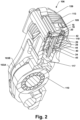
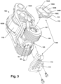
- FIG. 1-4 illustrate a valvetrain 100 with rocker arm assemblies 106.
- Rocker arm assemblies 106 include outer arms 103A, inner arms 103B, and cam followers 110.
- Valvetrain 100 is suitable for an internal combustion engine of a type that has combustion chambers, moveable valves having seats formed in the combustion chambers, and a camshaft.
- Rocker arm assemblies 106 may be installed in such an engine on pivots 140 in a configuration in which cams (not shown) on the camshaft engage cam followers 110 as the camshaft rotates.
- cams not shown
- rocker arms 103A and 103B When rocker arms 103A and 103B are engaged, the action of the cams of the cam followers 110 is operative to actuate the moveable valves (not shown) via rocker arm assemblies 106.
- Rocker arm assemblies 106 may be cylinder deactivating rocker arms. With reference to Fig. 2 , cylinder deactivation is controlled by electromagnetic latch assemblies 20, one of which is mounted to each rocker arm assembly 106. Electromagnetic latch assemblies 20 each include a latch pin 117 that has extended and retracted positions. Fig. 2 shows latch pin 117 in the retracted position. When latch pin 117 is in the retracted position, rocker arms 103A and 103B are in a disengaged configuration. In the disengaged configuration, outer arm 103A may remain stationary even as inner arm 103B is driven to pivot through cam follower 110. In this configuration, a valve actuated by rocker arm assembly 106 may be disabled.
- Latch pin 117 may be extended to place rocker arms 103A and 103B in an engaging configuration.
- outer arm 103A may pivot in conjunction with inner arm 103B and a valve actuated by rocker arm assembly 106 may opened and closed in conjunction with actuation of rocker arm assembly 106 through cam follower 110.
- Providing additional cams that operate directly on outer arm 103A can convert rocker arm assembly 106 into a two-step rocker arm providing two alternative valve lift profiles.
- Electromagnetic latch assembly 20 includes permanent magnets 24 and 26, and an electromagnet 119, which is operative to actuate latch pin 117 between the extended and retracted positions.
- the operation of these components is illustrated by the sketches of Figs. 5-7.
- Fig. 5 illustrates electromagnetic latch assembly 20 with latch pin 117 in the extended position, which is a first limit of travel for latch pin 117.
- Fig. 7 illustrates electromagnetic latch assembly 20 with latch pin 117 in the retracted position, which is a second limit of travel for latch pin 117.
- Electromagnet 119 is operative to cause latch pin 117 to translate between the extended and retracted positions.
- Fig. 6 illustrates the magnet field generated by electromagnet 119 to initiate the transition from the extended to the retracted position.
- Permanent magnets 24 and 26 are each operative to stabilize the position of latch pin 117 in each of the extended and retracted positions. As illustrated in Figs. 5 and 7 , permanent magnets 24 and 26 utilize different magnetic circuits depending on whether latch pin 117 is in the extended or the retracted position. Pole pieces 40 and 42 form a clam shell around electromagnet 119, which completes some of these magnetic circuits. Latch pin 117 has a magnetically susceptible ferrule 44 around a paramagnetic core 45. Ferrule 44 is within these magnetic circuits and is the part through which permanent magnets 24 and 26 exert forces on latch pin 117. Magnetic circuits have characteristics as described herein, but it should be appreciated that the illustrations of these magnetic circuits are only approximate.
- a paramagnetic material is one that does not interact strongly with magnetic fields.
- Aluminum is an example of a paramagnetic material.
- a magnetically susceptible material is generally a low coercivity ferromagnetic material.
- Soft iron is an example of a low coercivity ferromagnetic material.
- Pole pieces 28, 40, and 42 and ferrule 44 may all be made from soft iron.
- magnetic circuit 32 is the primary path for an operative portion of the magnet flux from magnet 24 when latch pin 117 is in the extended position, absent magnetic fields from electromagnet 119 or any external source that might alter the path taken by flux from magnet 24.
- the operative portion of the flux is that portion of the magnetic flux which contributes to the stability of latch pin 117 in its current position.
- Magnetic circuit 32 proceeds from the north pole of magnet 24, through pole piece 28, through ferrule 44, through an edge of pole piece 40, and ends at the south pole of magnet 24. Perturbation of latch pin 117 from the extended position would introduce an air gap into magnetic circuit 32, increasing its magnetic reluctance. The magnetic forces produced by magnet 24 resist such perturbations.
- magnetic circuit 34 is the primary path for an operative portion of the magnet flux from magnet 24.
- Magnetic circuit 34 proceeds from the north pole of magnet 24, through pole piece 28, through ferrule 44, through pole piece 42, through pole pieces 40, and ends at the south pole of magnet 24. Perturbations of latch pin 117 from the retracted position would introduce an air gap into magnetic circuit 34, increasing its magnetic reluctance. The magnetic forces produced by magnet 24 resist such perturbations.
- Magnet 26 is also operative to stabilize latch pin 117 in both the extended and retracted positions. As shown in Figs. 5 and 7 , magnetic circuit 36 is the primary path for an operative portion of the magnet flux from magnet 26 when latch pin 117 is in the extended position and magnetic circuit 38 is the primary path for an operative portion of the magnet flux from magnet 26 when latch pin 117 is in the retracted position.
- Electromagnetic latch assembly 20 is structured to operate through a magnetic flux shifting mechanism.
- electromagnet 119 is operable to alter the path taken by flux from permanent magnets 24 and 26.
- Fig. 6 illustrates the mechanism for this action in the case of operating electromagnet 119 to induce latch pin 117 to actuate from the extended position to the retracted position.
- Current through electromagnet 119 results in magnetic flux that follows the circuit 39. If the current has a suitable magnitude and direction, the flux reverses magnetic polarities in ferrule 44 and pole pieces 40 and 42. This greatly increase the reluctance of magnetic circuits 32 and 36 causing flux following those circuits to shift toward magnetic circuits 34 and 38.
- the net magnetic forces on latch pin 117 may drive it to the retracted position shown in Fig. 7 .
- electromagnetic latch assembly 20 which includes electromagnet 119, may be installed in rocker arm 103A through opening 125 at the back of rocker arms 103A.
- Electromagnet 119 has a first terminal 18 and a second terminal 19.
- wires 113 couple first terminal 18 to contact pad 104A and second terminal 19 to contact pad 104B.
- contact pad 104B may be used to form a ground connection
- the present teachings provide for an alternative configuration in which second terminal 19 is grounded by a connection to rocker arm 103A or another load-bearing component of rocker arm assembly 106.
- This alternative configuration eliminates the need for contact pad 104B and the electrical connection made through contact pad 104B.
- Bracket 109 which may be press fit into opening 125, mounts contacts pads 104A and 104B to outer arm 103A and holds contacts pads 104A and 104B to one side of outer arm 103A over spring post 157. Bracket 119 may also support wires 113. Bracket 109 may include a part 111 held at the back of rocker arm 103A and a part 112 held to the side of rocker arm 103A. Optionally, parts 111 and 112 are provided as a single part. Such a part may be formed by over-molding wires 113 and contacts pads 104A and 104B.
- Electromagnet 119 may be powered through electrical connections formed by abutment between spring-loaded pins 107A and 107B and contact pads 104A and 104B.
- Contact pads 104A and 104B are mounted to rocker arm 103A and move in conjunction with rocker arm 103A.
- Spring-loaded pins 107A and 107B are mounted to components distinct from rocker arm assembly 106, whereby rocker arm 103A moves independently from spring-loaded pins 107A and 107B.
- Spring-loaded pins 107A and 107B are held against contact pads 104A and 104B respectively by framework 120.
- framework 120 may include a base plate 114 and slip ring towers 115.
- Base plate 114 may include cutouts 124 that fit around pivots 140.
- baseplate 114 When framework 120 is installed in an engine, baseplate 114 may rest atop a cylinder head (not shown) and abut two pivots 140. Cutouts 124 may cooperate with pivots 140 to ensure proper positioning of framework 120 with respect to rocker arm assemblies 106 and therefore proper position of spring-loaded pins 107 with respect to contact pads 104.
- Framework 120 may be secured to the cylinder head by bolts passing through openings 116. This structure holds spring-loaded pins 107 stationary relative to the cylinder head even as contact pads 104 pivot in relation to the movement of rocker arm 103A.
- contact pads 104A and 104B have planar contact surfaces 105A and 105B respectively.
- Each rocker arm assembly 106 pivots on a pivot 140, which may be a hydraulic lash adjuster.
- Outer arm 103A and inner arm 103B are free to pivot relative to one-another except when they are engaged by latch pin 117.
- Pivot 140 may raise or lower rocker arm assembly 106 to adjust lash.
- Spring-loaded pin 107B may remain in abutment with contact surface 105B throughout rocker arm 103A's range of motion.
- Spring-loaded pin 107A may remain in abutment with contact surface 105A through only a portion of rocker arm 103A's range of motion.
- Contact pad 104A may be structured and positioned such that as rocker arm 103A is lifted off base circle, spring-loaded pin 107A moved from abutment with contact surface 105A to abutment with contact surface 105C.
- Connection through contact surface 105C may present a distinctly higher resistance than connection through contact surface 105A.
- the higher resistance may be provided by a coating on contact surface 105C that is not present on contact surface 105A. That coating may be a diamond-like carbon (DLC) coating. The difference in resistance may be used to detect the position of rocker arm 103A.
- DLC diamond-like carbon
- any suitable structure may be used to mount contact pads 104 to rocker arm 103A.
- spring-loaded pins 107 could be mounted to any suitable part that is distinct from rocker arm 103A. Spring-loaded pins 107 may be mounted to that distinct part by any suitable structure.
- Contact pads 104 may be the parts mounted to components distinct from rocker arm 103A while spring-loaded pins 107 may be mounted to rocker arm 103A. Pins 107 could be replaced by pins without springs.
- Contact pads 104 could be formed with leaf springs to bias pins 107 and contact pads 104 into abutment. Suitable contacts could also be formed with rollers or motor brushes.
- connection there is at least one electrical connection formed by abutting surfaces one of which rolls or slides relative to the other in relation to rocker arm 103A being lifted by a cam.
- present teachings are particularly useful when such a connection is present, but they extend to situations in which there is no such connection.
- Electromagnet 119 is powered by circuitry that provides electromagnet 119 with DC current that is selectively either in a forward or a reverse direction.
- a conventional solenoid switch forms a magnetic circuit that include an air gap, a spring that tends to enlarge the air gap, and an armature moveable to reduce the air gap. Moving the armature to reduce the air gap reduces the magnetic reluctance of that circuit. Consequently, energizing a conventional solenoid switch causes the armature to move in the direction that reduces the air gap regardless of the direction of the current through the solenoid's coil or the polarity of the resulting magnetic field. As described above, however, the direction in which latch pin 117 is actuated depends on the polarity of the magnetic field generated by electromagnet 119, which in turn depends on the direction of current through electromagnet 119.
- first terminal 18 of electromagnet 119 may be connected to a 12V power source while second terminal 19 of electromagnet 119 is connected to ground.
- first terminal 18 may be connected to ground while second terminal 19 is connected to a 12V power source.
- An H-bridge circuit would typically be used to implement that functionality.
- the present teachings provide circuits that allow second terminal 19 to always be grounded while still allowing electromagnet 119 to be powered with a DC current that is selectively either in a forward or a reverse direction.
- Fig. 8 provides a drawing of a circuit 300 through which a plurality of electromagnets 119 may be powered in the desired manner.
- Circuit 300 includes impulse generator 301, half bridge circuit 302A, and half bridge circuit 302B, which together form actuator control system 304.
- actuator control system 304 When coupled to 12V DC power source 308, actuator control system 304 is operative to provide pulses of DC current in either a forward or a reverse direction to the electromagnets 119 in either a first group 307A or a second group 307B.
- the first group 307A corresponds to the valves for a first engine cylinder and the second group 307B the valves of a second engine cylinder. Accordingly, four valves associated with one or the other engine cylinder may be activated or deactivated simultaneously.
- the number of electromagnet groups, the way the electromagnets are grouped, and the number of electromagnets in each group may all be varied.
- Impulse generator 301 is an inverting DC/DC converter.
- an inverting DC-to-DC converter is any electronic device that when powered by a DC current having a first polarity is operative to provide a DC current having second polarity, which is opposite that of the first.
- Impulse generator 301 includes capacitor 310 and switches 305A, 305B, and 305C.
- Capacitor 310 is charged by turning switches 305A and 305B on while keeping switch 305C off. While capacitor 310 is charging, actuator control system 304 supplies DC current in a first direction be transmitting that current from power source 308. When switches 305A and 305B are off and switch 305C is on, capacitor 310 discharges to supply DC current in the second direction.
- Fig. 9 provides plots illustrating the operation of impulse generator 301 and half bridge circuit 302A, and by extension, half bridge circuit 302B.
- the upper plot shows the switching pattern.
- the lower plot shows the time variation in voltage on the left hand side of capacitor 310 and of current provided actuator control system 304.
- switches 305A, 305B, and 306A are on.
- Turning switch 306A on results in actuator control system 304 providing a positive current.
- Turning switches 305A and 305B on results in capacitor 310 being charged.
- switch 306A is off.
- Switches 305A and 305B remain on and capacitor 310 continues to charge to the extent it is not fully charged already.
- switches 305A and 305B are cycled on and off whenever capacitor 310 is charging to regulate its charging rate.
- switches 305A, 305B, and 306A are off.
- Switches 305C and 306B are on.
- Switch 305C connects one side of capacitor 310 to ground 309. As capacitor 310 discharges, it pulls a negative current through switch 306B. As shown in Fig. 9 , voltages on the left-hand side of capacitor 310 remain above ground. But voltages on the right-hand side of capacitor 310, and by extension at terminals 18 of electromagnets 119, are pulled below ground.
- Capacitor 310 is sized to ensure that the current is sufficient to actuate a set of latches 117. Making the largest number of electromagnets in a group smaller would reduce the required size of capacitor 310. While the example shows four electromagnets per group, in some of these teachings the number of electromagnets 119 per group 307 is limited to two. In some of these teachings, the number of electromagnets 119 per group 307 is limited to one. For period "V", switches 305C and 306B are off, switches 305A and 305B are on, and capacitor 310 is once again charged.
- Fig. 10 is a finite state machine diagram illustrating an example method of operating valvetrain 100 using latch control module 300.
- state 350 which may be the default state when valvetrain 100 is operating.
- switches 305A are 305B are on and capacitor 310 is charging. All other switches are off.
- a command to deactivate Cylinder 1 causes a transition to state 351.
- the transition may be delayed until all the rocker arm assemblies 106 associated with Cylinder 1 are within a switching window.
- a switching window may be a period in which latching or unlatching may be completed while all the cams operating on the rocker arm assemblies 106 are on base circle.
- switch 306A is on.
- switches 305A and 305B are kept on allowing capacitor 310 to continue to charge. All other switches are off.
- State 351 causes the latches 117 of the rocker arm assemblies 106 that control actuation of Cylinder 1's valves (not shown) to be disengaged, which deactivates Cylinder 1.
- latch control module 300 After actuation is complete, latch control module 300 returns to the default state 350.
- the return to state 350 may be based on elapsed time or in any other suitable way. In some of these teachings, the return occurs within 0.1 second or less. Preferably, the return occurs within 0.05 seconds or less. More preferably, the return occurs without 0.02 seconds or less.
- State 353 is a counterpart to state 351 for deactivating Cylinder 2. State 353 is the same as state 351 except that switch 303A is on. Optionally, switches 305A and 305B are kept on allowing capacitor 310 to continue to charge.
- a command to activate Cylinder 1 causes a transition to state 352.
- switches 305C, and 306B are on. All other switches are off.
- State 352 causes the latches 117 of the rocker arm assemblies 106 that control actuation of Cylinder 1's valves to be re-engaged, which activates Cylinder 1.
- latch control module 300 again returns to the default state 350.
- State 354 is a counterpart to state 352 for reactivating Cylinder 2. State 354 is the same as state 352 except that switch 303B is on and switch 306B is off.
Landscapes
- Engineering & Computer Science (AREA)
- Mechanical Engineering (AREA)
- General Engineering & Computer Science (AREA)
- Valve Device For Special Equipments (AREA)
Claims (11)
- Ventiltrieb (100) für einen Verbrennungsmotor eines Typs, der eine Verbrennungskammer, ein bewegliches Ventil, das einen in der Verbrennungskammer ausgebildeten Sitz aufweist, und eine Nockenwelle aufweist, wobei der Ventiltrieb (100) umfasst:eine Vielzahl von Kipphebelanordnungen (106), die jeweils einen Kipphebel (103A, 103B), einen Verriegelungsstift (117) und einen Nockenstößel (110) umfassen, der so konfiguriert ist, dass er in einen auf einer Nockenwelle montierten Nocken eingreift, wenn sich die Nockenwelle dreht;eine Vielzahl von Elektromagneten (119), die jeweils einen ersten und einen zweiten Anschluss (18, 19) aufweisen und jeweils betriebsfähig sind, um einen bestimmten der Verriegelungsstifte (117) zu betätigen; undein Aktuatorsteuerungssystem (304), das betriebsfähig ist, um dem ersten Anschluss (18) eines der Elektromagneten oder den ersten Anschlüssen (18) eines beliebigen ausgewählten einen einer Vielzahl von bestimmten Gruppen, die einen oder mehrere der Elektromagneten (119) umfassen, einen Gleichstrom bereitzustellen, der selektiv entweder in einer ersten Richtung oder in einer zweiten Richtung fließt;wobei die zweite Richtung die Umkehrung der ersten ist,wobei das Aktuatorsteuerungssystem (304) einen Impulsgenerator (301) umfasst, der Schaltelemente (305A, 305B, 305C) und einen oder mehrere Kondensatoren (310) aufweist, die betriebsfähig sind, um den Strom in der zweiten Richtung bereitzustellen, wobei der Impulsgenerator (301) ein invertierender DC/DC-Wandler ist, der durch einen Gleichstrom gespeist wird, der eine erste Polarität aufweist, um einen Gleichstrom bereitzustellen, der eine zweite Polarität aufweist, die der ersten entgegengesetzt ist.
- Ventiltrieb (100) nach Anspruch 1, der ferner eine oder mehrere Halbbrückenschaltungen (302A, 302B) umfasst, die eingerichtet sind, um dem Aktuatorsteuerungssystem zu ermöglichen, die Ströme in der zweiten Richtung aus dem Impulsgenerator über die eine oder die mehreren Halbbrückenschaltungen (302A, 302B) dem/den Elektromagneten (119) bereitzustellen.
- Ventiltrieb (100) nach Anspruch 1 oder 2, wobei die zweiten Anschlüsse (19) geerdet sind.
- Ventiltrieb (100) nach einem der Ansprüche 1 bis 3, wobei die zweiten Anschlüsse (19) über die Strukturen der Kipphebelanordnungen (106) geerdet sind.
- Ventiltrieb (100) nach einem der Ansprüche 1 bis 4, der ferner Permanentmagnete (24, 26) umfasst, die konfiguriert sind, um die Verriegelungsstifte (117) sowohl in ausgefahrener als auch in eingefahrener Position festzuhalten.
- Ventiltrieb (100) nach einem der Ansprüche 1 bis 5, wobei:die Elektromagnete (119) an den Kipphebeln (103A, 103B) montiert sind;elektrische Verbindungen zwischen dem Aktuatorsteuerungssystem (304) und den Elektromagneten (119) durch Anliegen zwischen Oberflächen bestimmter Teile hergestellt sind, von denen eines an dem Kipphebel (103A, 103B) montiert ist, der den Elektromagneten (119) trägt, und das andere an einem bestimmten Teil, sodass die Kipphebelanordnung (106) betriebsfähig ist, um eine der Anlageflächen im Verhältnis zu der anderen als Reaktion auf die Betätigung der Kipphebelanordnung (106) durch den Nockenstößel zu bewegen; unddie elektrischen Anschlüsse gegenüber Erde isoliert sind.
- Motor, der umfasst:einen Zylinderkopf; undeinen Ventiltrieb nach einem der Ansprüche 1 bis 6;wobei die zweiten Anschlüsse (19) der Elektromagneten (119) an dem Zylinderkopf geerdet sind.
- Verfahren zum Betreiben von Elektromagneten, die jeweils erste und zweite Anschlüsse aufweisen und jeweils betriebsfähig sind, um einen Verriegelungsstift oder eine bestimmte Gruppe aus einem oder mehreren Verriegelungsstiften in einer Vielzahl von Kipphebelanordnungen eines Ventiltriebs für einen Verbrennungsmotor eines Typs zu betätigen, der eine Verbrennungskammer, ein bewegliches Ventil, das einen in der Verbrennungskammer ausgebildeten Sitz aufweist, und eine Nockenwelle aufweist, wobei das Verfahren umfasst:Bereitstellen eines Gleichstroms in einer ersten Richtung aus einer Stromquelle für den ersten Anschluss eines der Elektromagneten, wobei der Gleichstrom in der ersten Richtung den/die Verriegelungsstift/e aus einer ersten Position in eine zweite Position betätigt;Laden eines oder mehrerer Kondensatoren in einem Impulsgenerator mit Strom aus der Stromquelle, wobei der Impulsgenerator (301) ein invertierender DC/DC-Wandler ist, der durch einen Gleichstrom gespeist wird, der eine erste Polarität aufweist, um einen Gleichstrom bereitzustellen, der eine zweite Polarität aufweist, die der ersten entgegengesetzt ist; undBereitstellen eines Gleichstroms in einer zweiten Richtung, die eine Umkehrung der ersten Richtung ist, für den ersten Anschluss des Elektromagneten, wobei der zweite Gleichstrom aus einem oder mehreren Kondensatoren entnommen wird und der zweite Gleichstrom den/die Verriegelungsstift/e aus der zweiten Position in die erste Position betätigt.
- Verfahren nach Anspruch 8, das ferner das Installieren des Impulsgenerators als Teil des Ventiltriebsystems umfasst.
- Verfahren nach Anspruch 8 oder 9, wobei der Impulsgenerator ausschließlich durch das Ventiltriebsystem verwendet wird.
- Verfahren nach einem der Ansprüche 8 bis 10, wobei der zweite Anschluss der Elektromagnete stets geerdet ist.
Applications Claiming Priority (2)
| Application Number | Priority Date | Filing Date | Title |
|---|---|---|---|
| US201762582780P | 2017-11-07 | 2017-11-07 | |
| PCT/EP2018/080064 WO2019091874A1 (en) | 2017-11-07 | 2018-11-02 | Actuator control system for bi-stable electric rocker arm latches |
Publications (2)
| Publication Number | Publication Date |
|---|---|
| EP3707352A1 EP3707352A1 (de) | 2020-09-16 |
| EP3707352B1 true EP3707352B1 (de) | 2024-10-30 |
Family
ID=64100665
Family Applications (1)
| Application Number | Title | Priority Date | Filing Date |
|---|---|---|---|
| EP18796660.1A Active EP3707352B1 (de) | 2017-11-07 | 2018-11-02 | Aktuatorsteuerungssystem für bistabile elektrische kipphebelverriegelungen |
Country Status (4)
| Country | Link |
|---|---|
| US (1) | US11274579B2 (de) |
| EP (1) | EP3707352B1 (de) |
| CN (1) | CN111465752B (de) |
| WO (1) | WO2019091874A1 (de) |
Families Citing this family (1)
| Publication number | Priority date | Publication date | Assignee | Title |
|---|---|---|---|---|
| US11891923B2 (en) | 2019-09-10 | 2024-02-06 | Eaton Intelligent Power Limited | Valvetrain with rocker shaft housing magnetic latch |
Family Cites Families (11)
| Publication number | Priority date | Publication date | Assignee | Title |
|---|---|---|---|---|
| JPS59158506A (ja) * | 1983-02-28 | 1984-09-08 | Toshiba Corp | 電磁石装置 |
| US4682801A (en) * | 1984-08-31 | 1987-07-28 | Securitron-Magnalock Corp. | Electromagnet access control circuit |
| US5456224A (en) * | 1991-12-03 | 1995-10-10 | Motive Holdings Limited | Variable valve lift mechanism for internal combustion engine |
| JPH09144622A (ja) * | 1995-11-24 | 1997-06-03 | Toyota Motor Corp | インジェクタ駆動回路 |
| US8272357B2 (en) * | 2009-07-23 | 2012-09-25 | Lgd Technology, Llc | Crossover valve systems |
| KR101057894B1 (ko) * | 2009-09-22 | 2011-08-22 | 기아자동차주식회사 | 차량의 엔진브레이크 장치 |
| DE102012205695A1 (de) * | 2012-04-05 | 2013-10-10 | Schaeffler Technologies AG & Co. KG | Nockenfolger |
| US10180089B2 (en) * | 2014-08-18 | 2019-01-15 | Eaton Intelligent Power Limited | Valvetrain with rocker arm housing magnetically actuated latch |
| WO2016028465A1 (en) * | 2014-08-18 | 2016-02-25 | Eaton Corporation | Magnetically latching flux-shifting electromechanical actuator |
| JP6248871B2 (ja) * | 2014-09-05 | 2017-12-20 | 株式会社デンソー | 電磁アクチュエータ |
| WO2017091799A1 (en) * | 2015-11-25 | 2017-06-01 | Eaton Corporation | Rocker arm assembly having an electrical connection made between abutting surfaces that undergo relative motion |
-
2018
- 2018-11-02 US US16/761,973 patent/US11274579B2/en active Active
- 2018-11-02 EP EP18796660.1A patent/EP3707352B1/de active Active
- 2018-11-02 WO PCT/EP2018/080064 patent/WO2019091874A1/en not_active Ceased
- 2018-11-02 CN CN201880079280.6A patent/CN111465752B/zh active Active
Also Published As
| Publication number | Publication date |
|---|---|
| US11274579B2 (en) | 2022-03-15 |
| CN111465752B (zh) | 2022-07-26 |
| US20210189920A1 (en) | 2021-06-24 |
| WO2019091874A1 (en) | 2019-05-16 |
| CN111465752A (zh) | 2020-07-28 |
| EP3707352A1 (de) | 2020-09-16 |
Similar Documents
| Publication | Publication Date | Title |
|---|---|---|
| EP3183437B1 (de) | Verfahren zum einbau eines ventiltriebes in einem verbrennungsmotor | |
| US12116909B2 (en) | Auxiliary framework for electrically latched rocker arms | |
| US10180089B2 (en) | Valvetrain with rocker arm housing magnetically actuated latch | |
| US11008900B2 (en) | Sliding contact for electrically actuated rocker arm | |
| US10731517B2 (en) | Valvetrain with rocker arm housing magnetic latch | |
| US20190257227A1 (en) | Inductive coupling to rocker arm assemblies | |
| EP4028649B1 (de) | Ventiltrieb mit magnetischer verriegelung des kipphebelgehäuses | |
| EP3707352B1 (de) | Aktuatorsteuerungssystem für bistabile elektrische kipphebelverriegelungen | |
| CN104798147B (zh) | 电磁调节设备 | |
| CN109996937B (zh) | 电动闩锁摇臂的辅助框架 | |
| WO2021143995A1 (en) | Electromagnetic latch systems for rocker arm assemblies | |
| US10900390B2 (en) | Harsh condition controls for electrically latched switching roller finger follower | |
| EP0778592B1 (de) | Elektromagnetischer Betätiger mit Kern mit niedrigem Seitenverhältnis | |
| WO2018217536A2 (en) | Magnetic actuator for switching roller finger followers | |
| KR101362262B1 (ko) | 하이브리드 자석 엔진 밸브 액츄에이터 | |
| US11225885B2 (en) | Rocker arm motion detection for diagnostic feedback and control |
Legal Events
| Date | Code | Title | Description |
|---|---|---|---|
| STAA | Information on the status of an ep patent application or granted ep patent |
Free format text: STATUS: UNKNOWN |
|
| STAA | Information on the status of an ep patent application or granted ep patent |
Free format text: STATUS: THE INTERNATIONAL PUBLICATION HAS BEEN MADE |
|
| PUAI | Public reference made under article 153(3) epc to a published international application that has entered the european phase |
Free format text: ORIGINAL CODE: 0009012 |
|
| STAA | Information on the status of an ep patent application or granted ep patent |
Free format text: STATUS: REQUEST FOR EXAMINATION WAS MADE |
|
| 17P | Request for examination filed |
Effective date: 20200529 |
|
| AK | Designated contracting states |
Kind code of ref document: A1 Designated state(s): AL AT BE BG CH CY CZ DE DK EE ES FI FR GB GR HR HU IE IS IT LI LT LU LV MC MK MT NL NO PL PT RO RS SE SI SK SM TR |
|
| AX | Request for extension of the european patent |
Extension state: BA ME |
|
| DAV | Request for validation of the european patent (deleted) | ||
| DAX | Request for extension of the european patent (deleted) | ||
| STAA | Information on the status of an ep patent application or granted ep patent |
Free format text: STATUS: EXAMINATION IS IN PROGRESS |
|
| 17Q | First examination report despatched |
Effective date: 20221019 |
|
| P01 | Opt-out of the competence of the unified patent court (upc) registered |
Effective date: 20230521 |
|
| GRAP | Despatch of communication of intention to grant a patent |
Free format text: ORIGINAL CODE: EPIDOSNIGR1 |
|
| STAA | Information on the status of an ep patent application or granted ep patent |
Free format text: STATUS: GRANT OF PATENT IS INTENDED |
|
| INTG | Intention to grant announced |
Effective date: 20240521 |
|
| GRAS | Grant fee paid |
Free format text: ORIGINAL CODE: EPIDOSNIGR3 |
|
| GRAA | (expected) grant |
Free format text: ORIGINAL CODE: 0009210 |
|
| STAA | Information on the status of an ep patent application or granted ep patent |
Free format text: STATUS: THE PATENT HAS BEEN GRANTED |
|
| AK | Designated contracting states |
Kind code of ref document: B1 Designated state(s): AL AT BE BG CH CY CZ DE DK EE ES FI FR GB GR HR HU IE IS IT LI LT LU LV MC MK MT NL NO PL PT RO RS SE SI SK SM TR |
|
| REG | Reference to a national code |
Ref country code: GB Ref legal event code: FG4D |
|
| REG | Reference to a national code |
Ref country code: CH Ref legal event code: EP |
|
| REG | Reference to a national code |
Ref country code: IE Ref legal event code: FG4D |
|
| REG | Reference to a national code |
Ref country code: DE Ref legal event code: R096 Ref document number: 602018076034 Country of ref document: DE |
|
| REG | Reference to a national code |
Ref country code: LT Ref legal event code: MG9D |
|
| REG | Reference to a national code |
Ref country code: NL Ref legal event code: MP Effective date: 20241030 |
|
| PG25 | Lapsed in a contracting state [announced via postgrant information from national office to epo] |
Ref country code: HR Free format text: LAPSE BECAUSE OF FAILURE TO SUBMIT A TRANSLATION OF THE DESCRIPTION OR TO PAY THE FEE WITHIN THE PRESCRIBED TIME-LIMIT Effective date: 20241030 Ref country code: PT Free format text: LAPSE BECAUSE OF FAILURE TO SUBMIT A TRANSLATION OF THE DESCRIPTION OR TO PAY THE FEE WITHIN THE PRESCRIBED TIME-LIMIT Effective date: 20250228 Ref country code: IS Free format text: LAPSE BECAUSE OF FAILURE TO SUBMIT A TRANSLATION OF THE DESCRIPTION OR TO PAY THE FEE WITHIN THE PRESCRIBED TIME-LIMIT Effective date: 20250228 |
|
| PG25 | Lapsed in a contracting state [announced via postgrant information from national office to epo] |
Ref country code: NL Free format text: LAPSE BECAUSE OF FAILURE TO SUBMIT A TRANSLATION OF THE DESCRIPTION OR TO PAY THE FEE WITHIN THE PRESCRIBED TIME-LIMIT Effective date: 20241030 Ref country code: FI Free format text: LAPSE BECAUSE OF FAILURE TO SUBMIT A TRANSLATION OF THE DESCRIPTION OR TO PAY THE FEE WITHIN THE PRESCRIBED TIME-LIMIT Effective date: 20241030 |
|
| REG | Reference to a national code |
Ref country code: AT Ref legal event code: MK05 Ref document number: 1737057 Country of ref document: AT Kind code of ref document: T Effective date: 20241030 |
|
| PG25 | Lapsed in a contracting state [announced via postgrant information from national office to epo] |
Ref country code: BG Free format text: LAPSE BECAUSE OF FAILURE TO SUBMIT A TRANSLATION OF THE DESCRIPTION OR TO PAY THE FEE WITHIN THE PRESCRIBED TIME-LIMIT Effective date: 20241030 |
|
| PG25 | Lapsed in a contracting state [announced via postgrant information from national office to epo] |
Ref country code: ES Free format text: LAPSE BECAUSE OF FAILURE TO SUBMIT A TRANSLATION OF THE DESCRIPTION OR TO PAY THE FEE WITHIN THE PRESCRIBED TIME-LIMIT Effective date: 20241030 |
|
| PG25 | Lapsed in a contracting state [announced via postgrant information from national office to epo] |
Ref country code: NO Free format text: LAPSE BECAUSE OF FAILURE TO SUBMIT A TRANSLATION OF THE DESCRIPTION OR TO PAY THE FEE WITHIN THE PRESCRIBED TIME-LIMIT Effective date: 20250130 |
|
| PG25 | Lapsed in a contracting state [announced via postgrant information from national office to epo] |
Ref country code: LV Free format text: LAPSE BECAUSE OF FAILURE TO SUBMIT A TRANSLATION OF THE DESCRIPTION OR TO PAY THE FEE WITHIN THE PRESCRIBED TIME-LIMIT Effective date: 20241030 Ref country code: GR Free format text: LAPSE BECAUSE OF FAILURE TO SUBMIT A TRANSLATION OF THE DESCRIPTION OR TO PAY THE FEE WITHIN THE PRESCRIBED TIME-LIMIT Effective date: 20250131 Ref country code: AT Free format text: LAPSE BECAUSE OF FAILURE TO SUBMIT A TRANSLATION OF THE DESCRIPTION OR TO PAY THE FEE WITHIN THE PRESCRIBED TIME-LIMIT Effective date: 20241030 |
|
| PG25 | Lapsed in a contracting state [announced via postgrant information from national office to epo] |
Ref country code: PL Free format text: LAPSE BECAUSE OF FAILURE TO SUBMIT A TRANSLATION OF THE DESCRIPTION OR TO PAY THE FEE WITHIN THE PRESCRIBED TIME-LIMIT Effective date: 20241030 |
|
| PG25 | Lapsed in a contracting state [announced via postgrant information from national office to epo] |
Ref country code: RS Free format text: LAPSE BECAUSE OF FAILURE TO SUBMIT A TRANSLATION OF THE DESCRIPTION OR TO PAY THE FEE WITHIN THE PRESCRIBED TIME-LIMIT Effective date: 20250130 |
|
| REG | Reference to a national code |
Ref country code: CH Ref legal event code: PL |
|
| PG25 | Lapsed in a contracting state [announced via postgrant information from national office to epo] |
Ref country code: SM Free format text: LAPSE BECAUSE OF FAILURE TO SUBMIT A TRANSLATION OF THE DESCRIPTION OR TO PAY THE FEE WITHIN THE PRESCRIBED TIME-LIMIT Effective date: 20241030 |
|
| PG25 | Lapsed in a contracting state [announced via postgrant information from national office to epo] |
Ref country code: MC Free format text: LAPSE BECAUSE OF FAILURE TO SUBMIT A TRANSLATION OF THE DESCRIPTION OR TO PAY THE FEE WITHIN THE PRESCRIBED TIME-LIMIT Effective date: 20241030 |
|
| PG25 | Lapsed in a contracting state [announced via postgrant information from national office to epo] |
Ref country code: DK Free format text: LAPSE BECAUSE OF FAILURE TO SUBMIT A TRANSLATION OF THE DESCRIPTION OR TO PAY THE FEE WITHIN THE PRESCRIBED TIME-LIMIT Effective date: 20241030 |
|
| PG25 | Lapsed in a contracting state [announced via postgrant information from national office to epo] |
Ref country code: LU Free format text: LAPSE BECAUSE OF NON-PAYMENT OF DUE FEES Effective date: 20241102 |
|
| REG | Reference to a national code |
Ref country code: CH Ref legal event code: PL |
|
| PG25 | Lapsed in a contracting state [announced via postgrant information from national office to epo] |
Ref country code: EE Free format text: LAPSE BECAUSE OF FAILURE TO SUBMIT A TRANSLATION OF THE DESCRIPTION OR TO PAY THE FEE WITHIN THE PRESCRIBED TIME-LIMIT Effective date: 20241030 |
|
| PG25 | Lapsed in a contracting state [announced via postgrant information from national office to epo] |
Ref country code: CH Free format text: LAPSE BECAUSE OF NON-PAYMENT OF DUE FEES Effective date: 20241130 |
|
| PG25 | Lapsed in a contracting state [announced via postgrant information from national office to epo] |
Ref country code: RO Free format text: LAPSE BECAUSE OF FAILURE TO SUBMIT A TRANSLATION OF THE DESCRIPTION OR TO PAY THE FEE WITHIN THE PRESCRIBED TIME-LIMIT Effective date: 20241030 |
|
| PG25 | Lapsed in a contracting state [announced via postgrant information from national office to epo] |
Ref country code: SK Free format text: LAPSE BECAUSE OF FAILURE TO SUBMIT A TRANSLATION OF THE DESCRIPTION OR TO PAY THE FEE WITHIN THE PRESCRIBED TIME-LIMIT Effective date: 20241030 |
|
| PG25 | Lapsed in a contracting state [announced via postgrant information from national office to epo] |
Ref country code: CZ Free format text: LAPSE BECAUSE OF FAILURE TO SUBMIT A TRANSLATION OF THE DESCRIPTION OR TO PAY THE FEE WITHIN THE PRESCRIBED TIME-LIMIT Effective date: 20241030 |
|
| PG25 | Lapsed in a contracting state [announced via postgrant information from national office to epo] |
Ref country code: IT Free format text: LAPSE BECAUSE OF FAILURE TO SUBMIT A TRANSLATION OF THE DESCRIPTION OR TO PAY THE FEE WITHIN THE PRESCRIBED TIME-LIMIT Effective date: 20241030 |
|
| REG | Reference to a national code |
Ref country code: DE Ref legal event code: R097 Ref document number: 602018076034 Country of ref document: DE |
|
| REG | Reference to a national code |
Ref country code: BE Ref legal event code: MM Effective date: 20241130 |
|
| PLBE | No opposition filed within time limit |
Free format text: ORIGINAL CODE: 0009261 |
|
| STAA | Information on the status of an ep patent application or granted ep patent |
Free format text: STATUS: NO OPPOSITION FILED WITHIN TIME LIMIT |
|
| PG25 | Lapsed in a contracting state [announced via postgrant information from national office to epo] |
Ref country code: SE Free format text: LAPSE BECAUSE OF FAILURE TO SUBMIT A TRANSLATION OF THE DESCRIPTION OR TO PAY THE FEE WITHIN THE PRESCRIBED TIME-LIMIT Effective date: 20241030 |
|
| GBPC | Gb: european patent ceased through non-payment of renewal fee |
Effective date: 20250130 |
|
| 26N | No opposition filed |
Effective date: 20250731 |
|
| PG25 | Lapsed in a contracting state [announced via postgrant information from national office to epo] |
Ref country code: GB Free format text: LAPSE BECAUSE OF NON-PAYMENT OF DUE FEES Effective date: 20250130 Ref country code: BE Free format text: LAPSE BECAUSE OF NON-PAYMENT OF DUE FEES Effective date: 20241130 |
|
| PG25 | Lapsed in a contracting state [announced via postgrant information from national office to epo] |
Ref country code: FR Free format text: LAPSE BECAUSE OF NON-PAYMENT OF DUE FEES Effective date: 20241230 |
|
| PG25 | Lapsed in a contracting state [announced via postgrant information from national office to epo] |
Ref country code: IE Free format text: LAPSE BECAUSE OF NON-PAYMENT OF DUE FEES Effective date: 20241102 |
|
| PGFP | Annual fee paid to national office [announced via postgrant information from national office to epo] |
Ref country code: DE Payment date: 20251022 Year of fee payment: 8 |