EP3707037B1 - System and method in case of defect vehicle brake - Google Patents
System and method in case of defect vehicle brake Download PDFInfo
- Publication number
- EP3707037B1 EP3707037B1 EP18799495.9A EP18799495A EP3707037B1 EP 3707037 B1 EP3707037 B1 EP 3707037B1 EP 18799495 A EP18799495 A EP 18799495A EP 3707037 B1 EP3707037 B1 EP 3707037B1
- Authority
- EP
- European Patent Office
- Prior art keywords
- braking force
- brake
- braking system
- braking
- force
- Prior art date
- Legal status (The legal status is an assumption and is not a legal conclusion. Google has not performed a legal analysis and makes no representation as to the accuracy of the status listed.)
- Active
Links
Images



Classifications
-
- B—PERFORMING OPERATIONS; TRANSPORTING
- B60—VEHICLES IN GENERAL
- B60T—VEHICLE BRAKE CONTROL SYSTEMS OR PARTS THEREOF; BRAKE CONTROL SYSTEMS OR PARTS THEREOF, IN GENERAL; ARRANGEMENT OF BRAKING ELEMENTS ON VEHICLES IN GENERAL; PORTABLE DEVICES FOR PREVENTING UNWANTED MOVEMENT OF VEHICLES; VEHICLE MODIFICATIONS TO FACILITATE COOLING OF BRAKES
- B60T17/00—Component parts, details, or accessories of power brake systems not covered by groups B60T8/00, B60T13/00 or B60T15/00, or presenting other characteristic features
- B60T17/18—Safety devices; Monitoring
- B60T17/22—Devices for monitoring or checking brake systems; Signal devices
- B60T17/221—Procedure or apparatus for checking or keeping in a correct functioning condition of brake systems
-
- B—PERFORMING OPERATIONS; TRANSPORTING
- B60—VEHICLES IN GENERAL
- B60L—PROPULSION OF ELECTRICALLY-PROPELLED VEHICLES; SUPPLYING ELECTRIC POWER FOR AUXILIARY EQUIPMENT OF ELECTRICALLY-PROPELLED VEHICLES; ELECTRODYNAMIC BRAKE SYSTEMS FOR VEHICLES IN GENERAL; MAGNETIC SUSPENSION OR LEVITATION FOR VEHICLES; MONITORING OPERATING VARIABLES OF ELECTRICALLY-PROPELLED VEHICLES; ELECTRIC SAFETY DEVICES FOR ELECTRICALLY-PROPELLED VEHICLES
- B60L15/00—Methods, circuits, or devices for controlling the traction-motor speed of electrically-propelled vehicles
- B60L15/20—Methods, circuits, or devices for controlling the traction-motor speed of electrically-propelled vehicles for control of the vehicle or its driving motor to achieve a desired performance, e.g. speed, torque, programmed variation of speed
- B60L15/2009—Methods, circuits, or devices for controlling the traction-motor speed of electrically-propelled vehicles for control of the vehicle or its driving motor to achieve a desired performance, e.g. speed, torque, programmed variation of speed for braking
-
- B—PERFORMING OPERATIONS; TRANSPORTING
- B60—VEHICLES IN GENERAL
- B60L—PROPULSION OF ELECTRICALLY-PROPELLED VEHICLES; SUPPLYING ELECTRIC POWER FOR AUXILIARY EQUIPMENT OF ELECTRICALLY-PROPELLED VEHICLES; ELECTRODYNAMIC BRAKE SYSTEMS FOR VEHICLES IN GENERAL; MAGNETIC SUSPENSION OR LEVITATION FOR VEHICLES; MONITORING OPERATING VARIABLES OF ELECTRICALLY-PROPELLED VEHICLES; ELECTRIC SAFETY DEVICES FOR ELECTRICALLY-PROPELLED VEHICLES
- B60L3/00—Electric devices on electrically-propelled vehicles for safety purposes; Monitoring operating variables, e.g. speed, deceleration or energy consumption
- B60L3/0023—Detecting, eliminating, remedying or compensating for drive train abnormalities, e.g. failures within the drive train
- B60L3/0076—Detecting, eliminating, remedying or compensating for drive train abnormalities, e.g. failures within the drive train relating to braking
-
- B—PERFORMING OPERATIONS; TRANSPORTING
- B60—VEHICLES IN GENERAL
- B60L—PROPULSION OF ELECTRICALLY-PROPELLED VEHICLES; SUPPLYING ELECTRIC POWER FOR AUXILIARY EQUIPMENT OF ELECTRICALLY-PROPELLED VEHICLES; ELECTRODYNAMIC BRAKE SYSTEMS FOR VEHICLES IN GENERAL; MAGNETIC SUSPENSION OR LEVITATION FOR VEHICLES; MONITORING OPERATING VARIABLES OF ELECTRICALLY-PROPELLED VEHICLES; ELECTRIC SAFETY DEVICES FOR ELECTRICALLY-PROPELLED VEHICLES
- B60L58/00—Methods or circuit arrangements for monitoring or controlling batteries or fuel cells, specially adapted for electric vehicles
- B60L58/10—Methods or circuit arrangements for monitoring or controlling batteries or fuel cells, specially adapted for electric vehicles for monitoring or controlling batteries
-
- B—PERFORMING OPERATIONS; TRANSPORTING
- B60—VEHICLES IN GENERAL
- B60L—PROPULSION OF ELECTRICALLY-PROPELLED VEHICLES; SUPPLYING ELECTRIC POWER FOR AUXILIARY EQUIPMENT OF ELECTRICALLY-PROPELLED VEHICLES; ELECTRODYNAMIC BRAKE SYSTEMS FOR VEHICLES IN GENERAL; MAGNETIC SUSPENSION OR LEVITATION FOR VEHICLES; MONITORING OPERATING VARIABLES OF ELECTRICALLY-PROPELLED VEHICLES; ELECTRIC SAFETY DEVICES FOR ELECTRICALLY-PROPELLED VEHICLES
- B60L7/00—Electrodynamic brake systems for vehicles in general
- B60L7/10—Dynamic electric regenerative braking
- B60L7/18—Controlling the braking effect
-
- B—PERFORMING OPERATIONS; TRANSPORTING
- B60—VEHICLES IN GENERAL
- B60L—PROPULSION OF ELECTRICALLY-PROPELLED VEHICLES; SUPPLYING ELECTRIC POWER FOR AUXILIARY EQUIPMENT OF ELECTRICALLY-PROPELLED VEHICLES; ELECTRODYNAMIC BRAKE SYSTEMS FOR VEHICLES IN GENERAL; MAGNETIC SUSPENSION OR LEVITATION FOR VEHICLES; MONITORING OPERATING VARIABLES OF ELECTRICALLY-PROPELLED VEHICLES; ELECTRIC SAFETY DEVICES FOR ELECTRICALLY-PROPELLED VEHICLES
- B60L7/00—Electrodynamic brake systems for vehicles in general
- B60L7/24—Electrodynamic brake systems for vehicles in general with additional mechanical or electromagnetic braking
- B60L7/26—Controlling the braking effect
-
- B—PERFORMING OPERATIONS; TRANSPORTING
- B60—VEHICLES IN GENERAL
- B60T—VEHICLE BRAKE CONTROL SYSTEMS OR PARTS THEREOF; BRAKE CONTROL SYSTEMS OR PARTS THEREOF, IN GENERAL; ARRANGEMENT OF BRAKING ELEMENTS ON VEHICLES IN GENERAL; PORTABLE DEVICES FOR PREVENTING UNWANTED MOVEMENT OF VEHICLES; VEHICLE MODIFICATIONS TO FACILITATE COOLING OF BRAKES
- B60T1/00—Arrangements of braking elements, i.e. of those parts where braking effect occurs specially for vehicles
- B60T1/02—Arrangements of braking elements, i.e. of those parts where braking effect occurs specially for vehicles acting by retarding wheels
- B60T1/10—Arrangements of braking elements, i.e. of those parts where braking effect occurs specially for vehicles acting by retarding wheels by utilising wheel movement for accumulating energy, e.g. driving air compressors
-
- B—PERFORMING OPERATIONS; TRANSPORTING
- B60—VEHICLES IN GENERAL
- B60T—VEHICLE BRAKE CONTROL SYSTEMS OR PARTS THEREOF; BRAKE CONTROL SYSTEMS OR PARTS THEREOF, IN GENERAL; ARRANGEMENT OF BRAKING ELEMENTS ON VEHICLES IN GENERAL; PORTABLE DEVICES FOR PREVENTING UNWANTED MOVEMENT OF VEHICLES; VEHICLE MODIFICATIONS TO FACILITATE COOLING OF BRAKES
- B60T13/00—Transmitting braking action from initiating means to ultimate brake actuator with power assistance or drive; Brake systems incorporating such transmitting means, e.g. air-pressure brake systems
- B60T13/10—Transmitting braking action from initiating means to ultimate brake actuator with power assistance or drive; Brake systems incorporating such transmitting means, e.g. air-pressure brake systems with fluid assistance, drive, or release
- B60T13/24—Transmitting braking action from initiating means to ultimate brake actuator with power assistance or drive; Brake systems incorporating such transmitting means, e.g. air-pressure brake systems with fluid assistance, drive, or release the fluid being gaseous
- B60T13/46—Vacuum systems
- B60T13/52—Vacuum systems indirect, i.e. vacuum booster units
-
- B—PERFORMING OPERATIONS; TRANSPORTING
- B60—VEHICLES IN GENERAL
- B60T—VEHICLE BRAKE CONTROL SYSTEMS OR PARTS THEREOF; BRAKE CONTROL SYSTEMS OR PARTS THEREOF, IN GENERAL; ARRANGEMENT OF BRAKING ELEMENTS ON VEHICLES IN GENERAL; PORTABLE DEVICES FOR PREVENTING UNWANTED MOVEMENT OF VEHICLES; VEHICLE MODIFICATIONS TO FACILITATE COOLING OF BRAKES
- B60T13/00—Transmitting braking action from initiating means to ultimate brake actuator with power assistance or drive; Brake systems incorporating such transmitting means, e.g. air-pressure brake systems
- B60T13/10—Transmitting braking action from initiating means to ultimate brake actuator with power assistance or drive; Brake systems incorporating such transmitting means, e.g. air-pressure brake systems with fluid assistance, drive, or release
- B60T13/66—Electrical control in fluid-pressure brake systems
-
- B—PERFORMING OPERATIONS; TRANSPORTING
- B60—VEHICLES IN GENERAL
- B60T—VEHICLE BRAKE CONTROL SYSTEMS OR PARTS THEREOF; BRAKE CONTROL SYSTEMS OR PARTS THEREOF, IN GENERAL; ARRANGEMENT OF BRAKING ELEMENTS ON VEHICLES IN GENERAL; PORTABLE DEVICES FOR PREVENTING UNWANTED MOVEMENT OF VEHICLES; VEHICLE MODIFICATIONS TO FACILITATE COOLING OF BRAKES
- B60T13/00—Transmitting braking action from initiating means to ultimate brake actuator with power assistance or drive; Brake systems incorporating such transmitting means, e.g. air-pressure brake systems
- B60T13/10—Transmitting braking action from initiating means to ultimate brake actuator with power assistance or drive; Brake systems incorporating such transmitting means, e.g. air-pressure brake systems with fluid assistance, drive, or release
- B60T13/66—Electrical control in fluid-pressure brake systems
- B60T13/662—Electrical control in fluid-pressure brake systems characterised by specified functions of the control system components
-
- B—PERFORMING OPERATIONS; TRANSPORTING
- B60—VEHICLES IN GENERAL
- B60T—VEHICLE BRAKE CONTROL SYSTEMS OR PARTS THEREOF; BRAKE CONTROL SYSTEMS OR PARTS THEREOF, IN GENERAL; ARRANGEMENT OF BRAKING ELEMENTS ON VEHICLES IN GENERAL; PORTABLE DEVICES FOR PREVENTING UNWANTED MOVEMENT OF VEHICLES; VEHICLE MODIFICATIONS TO FACILITATE COOLING OF BRAKES
- B60T13/00—Transmitting braking action from initiating means to ultimate brake actuator with power assistance or drive; Brake systems incorporating such transmitting means, e.g. air-pressure brake systems
- B60T13/10—Transmitting braking action from initiating means to ultimate brake actuator with power assistance or drive; Brake systems incorporating such transmitting means, e.g. air-pressure brake systems with fluid assistance, drive, or release
- B60T13/66—Electrical control in fluid-pressure brake systems
- B60T13/72—Electrical control in fluid-pressure brake systems in vacuum systems or vacuum booster units
-
- B—PERFORMING OPERATIONS; TRANSPORTING
- B60—VEHICLES IN GENERAL
- B60T—VEHICLE BRAKE CONTROL SYSTEMS OR PARTS THEREOF; BRAKE CONTROL SYSTEMS OR PARTS THEREOF, IN GENERAL; ARRANGEMENT OF BRAKING ELEMENTS ON VEHICLES IN GENERAL; PORTABLE DEVICES FOR PREVENTING UNWANTED MOVEMENT OF VEHICLES; VEHICLE MODIFICATIONS TO FACILITATE COOLING OF BRAKES
- B60T17/00—Component parts, details, or accessories of power brake systems not covered by groups B60T8/00, B60T13/00 or B60T15/00, or presenting other characteristic features
- B60T17/18—Safety devices; Monitoring
-
- B—PERFORMING OPERATIONS; TRANSPORTING
- B60—VEHICLES IN GENERAL
- B60T—VEHICLE BRAKE CONTROL SYSTEMS OR PARTS THEREOF; BRAKE CONTROL SYSTEMS OR PARTS THEREOF, IN GENERAL; ARRANGEMENT OF BRAKING ELEMENTS ON VEHICLES IN GENERAL; PORTABLE DEVICES FOR PREVENTING UNWANTED MOVEMENT OF VEHICLES; VEHICLE MODIFICATIONS TO FACILITATE COOLING OF BRAKES
- B60T17/00—Component parts, details, or accessories of power brake systems not covered by groups B60T8/00, B60T13/00 or B60T15/00, or presenting other characteristic features
- B60T17/18—Safety devices; Monitoring
- B60T17/22—Devices for monitoring or checking brake systems; Signal devices
-
- B—PERFORMING OPERATIONS; TRANSPORTING
- B60—VEHICLES IN GENERAL
- B60T—VEHICLE BRAKE CONTROL SYSTEMS OR PARTS THEREOF; BRAKE CONTROL SYSTEMS OR PARTS THEREOF, IN GENERAL; ARRANGEMENT OF BRAKING ELEMENTS ON VEHICLES IN GENERAL; PORTABLE DEVICES FOR PREVENTING UNWANTED MOVEMENT OF VEHICLES; VEHICLE MODIFICATIONS TO FACILITATE COOLING OF BRAKES
- B60T7/00—Brake-action initiating means
- B60T7/12—Brake-action initiating means for automatic initiation; for initiation not subject to will of driver or passenger
-
- B—PERFORMING OPERATIONS; TRANSPORTING
- B60—VEHICLES IN GENERAL
- B60T—VEHICLE BRAKE CONTROL SYSTEMS OR PARTS THEREOF; BRAKE CONTROL SYSTEMS OR PARTS THEREOF, IN GENERAL; ARRANGEMENT OF BRAKING ELEMENTS ON VEHICLES IN GENERAL; PORTABLE DEVICES FOR PREVENTING UNWANTED MOVEMENT OF VEHICLES; VEHICLE MODIFICATIONS TO FACILITATE COOLING OF BRAKES
- B60T8/00—Arrangements for adjusting wheel-braking force to meet varying vehicular or ground-surface conditions, e.g. limiting or varying distribution of braking force
- B60T8/17—Using electrical or electronic regulation means to control braking
- B60T8/172—Determining control parameters used in the regulation, e.g. by calculations involving measured or detected parameters
-
- B—PERFORMING OPERATIONS; TRANSPORTING
- B60—VEHICLES IN GENERAL
- B60T—VEHICLE BRAKE CONTROL SYSTEMS OR PARTS THEREOF; BRAKE CONTROL SYSTEMS OR PARTS THEREOF, IN GENERAL; ARRANGEMENT OF BRAKING ELEMENTS ON VEHICLES IN GENERAL; PORTABLE DEVICES FOR PREVENTING UNWANTED MOVEMENT OF VEHICLES; VEHICLE MODIFICATIONS TO FACILITATE COOLING OF BRAKES
- B60T8/00—Arrangements for adjusting wheel-braking force to meet varying vehicular or ground-surface conditions, e.g. limiting or varying distribution of braking force
- B60T8/32—Arrangements for adjusting wheel-braking force to meet varying vehicular or ground-surface conditions, e.g. limiting or varying distribution of braking force responsive to a speed condition, e.g. acceleration or deceleration
- B60T8/34—Arrangements for adjusting wheel-braking force to meet varying vehicular or ground-surface conditions, e.g. limiting or varying distribution of braking force responsive to a speed condition, e.g. acceleration or deceleration having a fluid pressure regulator responsive to a speed condition
- B60T8/44—Arrangements for adjusting wheel-braking force to meet varying vehicular or ground-surface conditions, e.g. limiting or varying distribution of braking force responsive to a speed condition, e.g. acceleration or deceleration having a fluid pressure regulator responsive to a speed condition co-operating with a power-assist booster means associated with a master cylinder for controlling the release and reapplication of brake pressure through an interaction with the power assist device, i.e. open systems
-
- B—PERFORMING OPERATIONS; TRANSPORTING
- B60—VEHICLES IN GENERAL
- B60T—VEHICLE BRAKE CONTROL SYSTEMS OR PARTS THEREOF; BRAKE CONTROL SYSTEMS OR PARTS THEREOF, IN GENERAL; ARRANGEMENT OF BRAKING ELEMENTS ON VEHICLES IN GENERAL; PORTABLE DEVICES FOR PREVENTING UNWANTED MOVEMENT OF VEHICLES; VEHICLE MODIFICATIONS TO FACILITATE COOLING OF BRAKES
- B60T8/00—Arrangements for adjusting wheel-braking force to meet varying vehicular or ground-surface conditions, e.g. limiting or varying distribution of braking force
- B60T8/32—Arrangements for adjusting wheel-braking force to meet varying vehicular or ground-surface conditions, e.g. limiting or varying distribution of braking force responsive to a speed condition, e.g. acceleration or deceleration
- B60T8/88—Arrangements for adjusting wheel-braking force to meet varying vehicular or ground-surface conditions, e.g. limiting or varying distribution of braking force responsive to a speed condition, e.g. acceleration or deceleration with failure responsive means, i.e. means for detecting and indicating faulty operation of the speed responsive control means
-
- B—PERFORMING OPERATIONS; TRANSPORTING
- B60—VEHICLES IN GENERAL
- B60L—PROPULSION OF ELECTRICALLY-PROPELLED VEHICLES; SUPPLYING ELECTRIC POWER FOR AUXILIARY EQUIPMENT OF ELECTRICALLY-PROPELLED VEHICLES; ELECTRODYNAMIC BRAKE SYSTEMS FOR VEHICLES IN GENERAL; MAGNETIC SUSPENSION OR LEVITATION FOR VEHICLES; MONITORING OPERATING VARIABLES OF ELECTRICALLY-PROPELLED VEHICLES; ELECTRIC SAFETY DEVICES FOR ELECTRICALLY-PROPELLED VEHICLES
- B60L2240/00—Control parameters of input or output; Target parameters
- B60L2240/40—Drive Train control parameters
- B60L2240/54—Drive Train control parameters related to batteries
-
- B—PERFORMING OPERATIONS; TRANSPORTING
- B60—VEHICLES IN GENERAL
- B60T—VEHICLE BRAKE CONTROL SYSTEMS OR PARTS THEREOF; BRAKE CONTROL SYSTEMS OR PARTS THEREOF, IN GENERAL; ARRANGEMENT OF BRAKING ELEMENTS ON VEHICLES IN GENERAL; PORTABLE DEVICES FOR PREVENTING UNWANTED MOVEMENT OF VEHICLES; VEHICLE MODIFICATIONS TO FACILITATE COOLING OF BRAKES
- B60T2201/00—Particular use of vehicle brake systems; Special systems using also the brakes; Special software modules within the brake system controller
- B60T2201/03—Brake assistants
-
- B—PERFORMING OPERATIONS; TRANSPORTING
- B60—VEHICLES IN GENERAL
- B60T—VEHICLE BRAKE CONTROL SYSTEMS OR PARTS THEREOF; BRAKE CONTROL SYSTEMS OR PARTS THEREOF, IN GENERAL; ARRANGEMENT OF BRAKING ELEMENTS ON VEHICLES IN GENERAL; PORTABLE DEVICES FOR PREVENTING UNWANTED MOVEMENT OF VEHICLES; VEHICLE MODIFICATIONS TO FACILITATE COOLING OF BRAKES
- B60T2220/00—Monitoring, detecting driver behaviour; Signalling thereof; Counteracting thereof
- B60T2220/04—Pedal travel sensor, stroke sensor; Sensing brake request
-
- B—PERFORMING OPERATIONS; TRANSPORTING
- B60—VEHICLES IN GENERAL
- B60T—VEHICLE BRAKE CONTROL SYSTEMS OR PARTS THEREOF; BRAKE CONTROL SYSTEMS OR PARTS THEREOF, IN GENERAL; ARRANGEMENT OF BRAKING ELEMENTS ON VEHICLES IN GENERAL; PORTABLE DEVICES FOR PREVENTING UNWANTED MOVEMENT OF VEHICLES; VEHICLE MODIFICATIONS TO FACILITATE COOLING OF BRAKES
- B60T2270/00—Further aspects of brake control systems not otherwise provided for
- B60T2270/40—Failsafe aspects of brake control systems
- B60T2270/402—Back-up
-
- B—PERFORMING OPERATIONS; TRANSPORTING
- B60—VEHICLES IN GENERAL
- B60T—VEHICLE BRAKE CONTROL SYSTEMS OR PARTS THEREOF; BRAKE CONTROL SYSTEMS OR PARTS THEREOF, IN GENERAL; ARRANGEMENT OF BRAKING ELEMENTS ON VEHICLES IN GENERAL; PORTABLE DEVICES FOR PREVENTING UNWANTED MOVEMENT OF VEHICLES; VEHICLE MODIFICATIONS TO FACILITATE COOLING OF BRAKES
- B60T2270/00—Further aspects of brake control systems not otherwise provided for
- B60T2270/40—Failsafe aspects of brake control systems
- B60T2270/403—Brake circuit failure
-
- B—PERFORMING OPERATIONS; TRANSPORTING
- B60—VEHICLES IN GENERAL
- B60T—VEHICLE BRAKE CONTROL SYSTEMS OR PARTS THEREOF; BRAKE CONTROL SYSTEMS OR PARTS THEREOF, IN GENERAL; ARRANGEMENT OF BRAKING ELEMENTS ON VEHICLES IN GENERAL; PORTABLE DEVICES FOR PREVENTING UNWANTED MOVEMENT OF VEHICLES; VEHICLE MODIFICATIONS TO FACILITATE COOLING OF BRAKES
- B60T2270/00—Further aspects of brake control systems not otherwise provided for
- B60T2270/60—Regenerative braking
-
- B—PERFORMING OPERATIONS; TRANSPORTING
- B60—VEHICLES IN GENERAL
- B60T—VEHICLE BRAKE CONTROL SYSTEMS OR PARTS THEREOF; BRAKE CONTROL SYSTEMS OR PARTS THEREOF, IN GENERAL; ARRANGEMENT OF BRAKING ELEMENTS ON VEHICLES IN GENERAL; PORTABLE DEVICES FOR PREVENTING UNWANTED MOVEMENT OF VEHICLES; VEHICLE MODIFICATIONS TO FACILITATE COOLING OF BRAKES
- B60T2270/00—Further aspects of brake control systems not otherwise provided for
- B60T2270/60—Regenerative braking
- B60T2270/604—Merging friction therewith; Adjusting their repartition
-
- B—PERFORMING OPERATIONS; TRANSPORTING
- B60—VEHICLES IN GENERAL
- B60T—VEHICLE BRAKE CONTROL SYSTEMS OR PARTS THEREOF; BRAKE CONTROL SYSTEMS OR PARTS THEREOF, IN GENERAL; ARRANGEMENT OF BRAKING ELEMENTS ON VEHICLES IN GENERAL; PORTABLE DEVICES FOR PREVENTING UNWANTED MOVEMENT OF VEHICLES; VEHICLE MODIFICATIONS TO FACILITATE COOLING OF BRAKES
- B60T8/00—Arrangements for adjusting wheel-braking force to meet varying vehicular or ground-surface conditions, e.g. limiting or varying distribution of braking force
- B60T8/17—Using electrical or electronic regulation means to control braking
-
- B—PERFORMING OPERATIONS; TRANSPORTING
- B60—VEHICLES IN GENERAL
- B60T—VEHICLE BRAKE CONTROL SYSTEMS OR PARTS THEREOF; BRAKE CONTROL SYSTEMS OR PARTS THEREOF, IN GENERAL; ARRANGEMENT OF BRAKING ELEMENTS ON VEHICLES IN GENERAL; PORTABLE DEVICES FOR PREVENTING UNWANTED MOVEMENT OF VEHICLES; VEHICLE MODIFICATIONS TO FACILITATE COOLING OF BRAKES
- B60T8/00—Arrangements for adjusting wheel-braking force to meet varying vehicular or ground-surface conditions, e.g. limiting or varying distribution of braking force
- B60T8/26—Arrangements for adjusting wheel-braking force to meet varying vehicular or ground-surface conditions, e.g. limiting or varying distribution of braking force characterised by producing differential braking between front and rear wheels
- B60T8/266—Arrangements for adjusting wheel-braking force to meet varying vehicular or ground-surface conditions, e.g. limiting or varying distribution of braking force characterised by producing differential braking between front and rear wheels using valves or actuators with external control means
- B60T8/267—Arrangements for adjusting wheel-braking force to meet varying vehicular or ground-surface conditions, e.g. limiting or varying distribution of braking force characterised by producing differential braking between front and rear wheels using valves or actuators with external control means for hybrid systems with different kind of brakes on different axles
-
- B—PERFORMING OPERATIONS; TRANSPORTING
- B60—VEHICLES IN GENERAL
- B60Y—INDEXING SCHEME RELATING TO ASPECTS CROSS-CUTTING VEHICLE TECHNOLOGY
- B60Y2200/00—Type of vehicle
- B60Y2200/90—Vehicles comprising electric prime movers
- B60Y2200/91—Electric vehicles
-
- B—PERFORMING OPERATIONS; TRANSPORTING
- B60—VEHICLES IN GENERAL
- B60Y—INDEXING SCHEME RELATING TO ASPECTS CROSS-CUTTING VEHICLE TECHNOLOGY
- B60Y2200/00—Type of vehicle
- B60Y2200/90—Vehicles comprising electric prime movers
- B60Y2200/92—Hybrid vehicles
-
- B—PERFORMING OPERATIONS; TRANSPORTING
- B60—VEHICLES IN GENERAL
- B60Y—INDEXING SCHEME RELATING TO ASPECTS CROSS-CUTTING VEHICLE TECHNOLOGY
- B60Y2400/00—Special features of vehicle units
- B60Y2400/81—Braking systems
-
- Y—GENERAL TAGGING OF NEW TECHNOLOGICAL DEVELOPMENTS; GENERAL TAGGING OF CROSS-SECTIONAL TECHNOLOGIES SPANNING OVER SEVERAL SECTIONS OF THE IPC; TECHNICAL SUBJECTS COVERED BY FORMER USPC CROSS-REFERENCE ART COLLECTIONS [XRACs] AND DIGESTS
- Y02—TECHNOLOGIES OR APPLICATIONS FOR MITIGATION OR ADAPTATION AGAINST CLIMATE CHANGE
- Y02T—CLIMATE CHANGE MITIGATION TECHNOLOGIES RELATED TO TRANSPORTATION
- Y02T10/00—Road transport of goods or passengers
- Y02T10/60—Other road transportation technologies with climate change mitigation effect
- Y02T10/70—Energy storage systems for electromobility, e.g. batteries
-
- Y—GENERAL TAGGING OF NEW TECHNOLOGICAL DEVELOPMENTS; GENERAL TAGGING OF CROSS-SECTIONAL TECHNOLOGIES SPANNING OVER SEVERAL SECTIONS OF THE IPC; TECHNICAL SUBJECTS COVERED BY FORMER USPC CROSS-REFERENCE ART COLLECTIONS [XRACs] AND DIGESTS
- Y02—TECHNOLOGIES OR APPLICATIONS FOR MITIGATION OR ADAPTATION AGAINST CLIMATE CHANGE
- Y02T—CLIMATE CHANGE MITIGATION TECHNOLOGIES RELATED TO TRANSPORTATION
- Y02T10/00—Road transport of goods or passengers
- Y02T10/60—Other road transportation technologies with climate change mitigation effect
- Y02T10/72—Electric energy management in electromobility
Definitions
- Vehicles include braking systems in order to slow and stop the vehicle.
- Many vehicles utilize a frictional braking system, for example, a hydraulic system that forces brake pads against rotors, to provide a mechanical or frictional braking force to reduce the vehicle's speed.
- Such systems may include a brake booster.
- the brake booster provides additional braking power, typically proportional to the amount of force a driver exerts on the brake pedal.
- the patent application DE 10 2014 119329 A1 relates to a method for detecting a malfunction of a braking system.
- the patent application EP 0 800 975 A2 relates to a booster and a pressure amplifying device provided to perform a brake assist.
- the patent application GB 2 502 803 A relates to a brake control system for a motor vehicle that includes a controller operable in response to a braking request signal.
- the patent application US 2015/001916 A1 relates to a braking device for a vehicle which includes a power fail-safe mechanism which works to create frictional braking force at a wheel of the vehicle in the event of loss of electric power.
- the patent application JP 2015 110378 A relates to a vehicle braking system that generates a braking force in a vehicle.
- the patent application EP 2 998 173 A1 relates to a hydraulic brake system that comprises a first actuator for a regeneration coordination brake control and a second actuator for maintaining the stability of a vehicle in a hydraulic pressure passage between a master cylinder and a wheel cylinder.
- the patent application US 2004 054450 A relates to a coordinated brake control system of a hybrid brake system.
- the brake system of the vehicle may require extra braking force in order to stop the vehicle within a certain distance.
- additional brake force may be required from the driver in order to compensate for the lacking brake force.
- Less braking force may increase the stopping distance of the vehicle.
- Some vehicles, for example electric and hybrid vehicles, include regenerative braking systems. Additional braking force may be sourced from the regenerative braking system in order to compensate for the braking force lost due to the brake booster failure.
- the invention presented herein includes a braking system as defined by independent claim 1.
- the braking system includes a friction braking system, a regenerative braking system, and an electronic processor.
- the electronic processor is communicatively coupled to the friction braking system and the regenerative braking system.
- the electronic processor is configured to receive a driver brake request and determine a brake failure state.
- the brake failure state indicates a brake failure.
- the electronic processor applies a braking force based on the driver brake request.
- the braking force includes a frictional braking force generated by the friction braking system and a regenerative braking force generated by the regenerative braking system.
- the invention provides a method for braking a vehicle as defined by independent claim 5.
- the method includes receiving a driver brake request, the driver brake request including a mechanical braking force and determining a brake failure state, the brake failure state indicating a brake failure.
- the method further includes, in response to determining the brake failure state, applying a braking force based on the driver brake request.
- the braking force includes a hydraulic braking force generated by a friction braking system and a regenerative braking force generated by a regenerative braking system.
- embodiments may include hardware, software, and electronic components or modules that, for purposes of discussion, may be illustrated and described as if the majority of the components were implemented solely in hardware.
- the electronic based aspects may be implemented in software (for example, stored on non-transitory computer-readable medium) executable by one or more processors.
- control units and “controllers” described in the specification can include one or more processors, one or more memory modules including non-transitory computer-readable medium, one or more input/output interfaces, and various connections (for example, a system bus) connecting the components.
- each of the example systems presented herein is illustrated with a single exemplar of each of its component parts. Some examples may not describe or illustrate all components of the systems. Other embodiments may include more or fewer of each of the illustrated components, may combine some components, or may include additional or alternative components.
- FIG. 1 is a block diagram of one exemplary embodiment of a braking system 100.
- the braking system 100 is included in a vehicle 102.
- the braking system 100 includes an electronic controller 104, an input/output (I/O) interface 106, a regenerative braking system 108, a friction braking system 110, and other vehicle systems 112.
- the vehicle 102 further includes a front axle 114, a rear axle 116, a front left wheel 118, a front right wheel 120, a rear left wheel 122, a rear right wheel 124.
- the front left and right wheels 118 and 120 are coupled to the front axle 114.
- the rear left and right wheels 122 and 124 are coupled to the rear axle 116.
- the electronic controller 104, the regenerative braking system 108, the friction braking system 110, and the other vehicle systems 112, as well as other various modules and components of the vehicle 102 are coupled to each other by or through one or more control or data buses (for example, a CAN bus), which enable communication therebetween.
- control or data buses for example, a CAN bus
- the electronic controller 104 includes a plurality of electrical and electronic components that provide power, operational control, and protection to the components and modules within the electronic controller 104.
- the electronic controller 104 includes, among other things, an electronic processor (for example, an electronic microprocessor, microcontroller, or other suitable programmable device), and a memory (not shown).
- the electronic controller 104 is also connected to the input/output interface 106.
- the electronic processor, the memory, and the input/output interface 106, as well as the other various modules are connected by one or more control or data buses.
- the electronic controller 104 is implemented partially or entirely in hardware (for example, using a fieldprogrammable gate array (“FPGA”), an application specific integrated circuit (“ASIC”), or other devices.
- FPGA fieldprogrammable gate array
- ASIC application specific integrated circuit
- the memory can include one or more non-transitory computer-readable media, and includes a program storage area and a data storage area.
- “non-transitory computer-readable media” comprises all computer-readable media but does not consist of a transitory, propagating signal.
- the program storage area and the data storage area can include combinations of different types of memory, for example, read-only memory (“ROM”), random access memory (“RAM”), electrically erasable programmable read-only memory (“EEPROM”), flash memory, or other suitable digital memory devices.
- the electronic processor is connected to the memory and executes software, including firmware, one or more applications, program data, filters, rules, one or more program modules, and other executable instructions.
- the electronic processor retrieves from the memory and executes, among other things, instructions related to the control processes and methods described herein.
- the electronic controller 104 may include additional, fewer, or different components.
- the regenerative braking system 108 is coupled to an electric motor (e-motor) 109.
- the regenerative braking system 108 is configured to perform regenerative braking during braking maneuvers of the vehicle 102. Specifically, the regenerative braking system 108, during a braking maneuver, causes the e-motor 109 to act as a generator and stores or redistributes the power generated by the e-motor 109. The act of generating power creates a braking torque on the e-motor 109 that is transmitted to one or more of the wheels 118, 120, 122, and 124 that the e-motor 109 is coupled to to slow and/or stabalize the vehicle 102.
- e-motor electric motor
- the regenerative braking system 108 include more than one e-motor 109 each coupled or connected to at least one of the wheels 118, 120, 122, and 124.
- one e-motor may be connected to the front left wheel 118 and a second e-motor may be connected to the front right wheel 120. It should be understood any number of connections with any number of motors connected to any number of tires is possible in further embodiments.
- the friction braking system 110 is a braking system that utilizes a frictional braking force to inhibit the motion of one or more of the wheels 118, 120, 122, and 124 in order to slow and/or stop the vehicle 102.
- some or all of the wheels 118, 120, 122, and 124 are fitted with brake pads which apply a frictional braking force that inhibits the motion of the wheels 118, 120, 122, and 124.
- the friction braking system 110 is a conventional hydraulic braking system.
- the friction braking system 110 may include a brake booster 111.
- the brake booster 111 is configured to increase the force the brake pedal 128 exerts on the wheel 118, 120, 122, 124 of the vehicle 102.
- the vehicle 102 is a vehicle that includes a regenerative braking system 116, for example a hybrid or electric vehicle.
- the vehicle 102 may further include a battery 130.
- the battery 130 provides power to the e-motor 109 of the system 100.
- the vehicle 102 is an autonomous or self-driving car.
- the vehicle 102 requires human input to drive.
- the system 100 includes a brake pedal 128.
- the brake pedal 128 may be connected to the friction braking system 110.
- the vehicle 102 may be a two wheel or four wheel drive system.
- the other vehicle systems 112 include controllers, sensors, actuators, and the like for controlling aspects of the operation of the vehicle 102 (for example, acceleration, braking, shifting gears, and the like).
- the other vehicle systems 116 are configured to send and receive data relating to the operation of the vehicle 102 to and from the electronic controller 104.
- FIG. 2 is a flowchart of a method 200 for the braking system 100.
- the electronic controller 104 receives, as illustrated in FIG. 3 , a driver brake request 304.
- FIG. 3 is a block diagram 300 illustrating a total braking force 302 applied to a wheel (for example, the front left wheel 118) of the braking system 100 according to the method 200 of FIG. 2 .
- the driver brake request 304 produces a mechanical force 306.
- the mechanical force 306 is used by the brake booster 111 to produce an amplified braking force 314.
- the amount of amplified braking force 314 may be the resultant force from the brake booster 111 ( FIG. 1 ) in response and/or proportional to the mechanical force 306.
- the mechanical force 306 may be produced by a driver of the vehicle 102 that applies force to the brake pedal 128.
- the brake pedal is not directly linked to a hydraulic system, but instead is simply an input device where movement of the brake pedal is converted to an electric signal that may be used to generate the driver brake request 304 to control the braking system.
- the signal may be provided to a hydraulic pump to increase a brake pressure or in other instances the signal is provided to electric motors that cause a caliper to open and close with respect to a brake rotor.
- the driver brake request 304 is automatically generated by the vehicle 102 and the mechanical braking force 306 is applied automatically, for example, using an automated braking system (not shown).
- the electronic controller 104 provides a command 310 to the regenerative braking system 108 to generate a regenerative braking force 312.
- the total force 302 includes the regenerative braking force 312 from the regenerative braking system 110 and the frictional braking force 315 from the frictional braking system 110.
- the frictional braking force 315 includes both the mechanical force 306 and the amplified braking force 314.
- the frictional braking force 315 may include only the mechanical force 306 or the amplified braking force 314.
- total braking force 302 and its components are illustrated in FIG. 3 as being applied to one wheel, it should be understood that the total braking force 302 may also refer to overall braking force produced for all the wheels of the vehicle 102 and that the frictional braking force 315 and the regenerative braking force 312 may also refer to the sum of the braking force produced for all the wheels of the vehicle 102 by the braking systems 110 and 108 respectively.
- FIG. 4A illustrates a no brake failure state 400.
- the regenerative braking system 108 produces the regenerative braking force 312 and the friction braking system 110 produces a frictional braking force 315 including both the mechanical force 306 and the amplified brake force 314.
- the electronic controller 104 determines a brake failure state (described in more detail in regard to FIGS. 4B - 4D ).
- the brake failure state is a failure in the braking system 100.
- the determining the brake failure state may include determining a failure of functionality of the brake booster 111.
- the electronic controller 104 applies a braking force 302 (see FIG. 3 ) to one or more of the wheels (for example 118, 120, 122, and/or 124) based on the drive brake request 304.
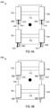
- FIGS. 4B through 4D each illustrate a different kind of brake failure state.
- determining the brake failure state include determining whether the brake failure state is a single brake circuit failure or a brake boost system failure (for example, a failure within the frictional braking system 108). As illustrated in FIG. 4B , in the case of a brake boost system failure, when the brake failure state is a brake boost system failure state 402, the amplified brake force 314 may be unavailable or, if available, may not be of sufficient magnitude to slow the vehicle 102.
- the regenerative braking force 312 is applied to the tires of a single axle (for example, either the front axle 114 or the rear axle 116) of the vehicle 102 and the mechanical force 306 is applied to all the tires 118, 120,122, and 124.
- the frictional braking force 315 for one or more of the tires 118, 120, 122, and 124 may be unavailable or, if available, may not be of sufficient magnitude to slow the vehicle 102.
- the regenerative braking force 312 is applied to a single axle (for example, either the front axle 114 or the rear axle 116) while the frictional braking force 314 (including both the mechanical braking force 306 and the amplified braking force is applied to the tires 118, 120, 122, and 124 so long as the single circuit failure has not affected the circuit between the particular tire and the frictional braking system 108.
- the friction braking system 110 may be a vertical split brake system or a diagonal split system.
- a vertical split brake system also called a front and rear split system
- the tires 118 and 120 on the front axle 114 are coupled to one brake circuit while the tires 122 and 124 are coupled to a second brake circuit.
- the tires 118 and 124 are coupled to one brake circuit while the tires 120 and 122 are coupled to a second brake circuit. In either case, a failure in one of the circuits results in a loss of braking force applied on two tires.
- the friction braking system 110 is a vertical split brake system (when the brake failure state is a vertical split brake failure state 404), the regenerative braking force 312 is applied on a single axle (for example, either the front axle 114 or the rear axle 116) of the vehicle 102, compensating for the lost frictional braking force 315 on the tires 118 and 120 due to the failure of the corresponding single braking circuit.
- the frictional braking force 315 resulting from the functional brake circuit (including both the mechanical braking force 306 and the amplified braking force 314) is applied to the tires 122 and 124 on the rear axle 116.
- the friction braking system 110 is a diagonal split brake system (when the brake failure state is a diagonal split brake failure state 406), the mechanical force 306 is unavailable.
- the regenerative braking force 312 is applied to a single axle (for example, either the front axle 114 or the rear axle 116) of the vehicle 102 while the frictional force 314 (including both the mechanical braking force 306 and the amplified braking force 314) is applied to the tires perpendicular to each other depending on the circuit failure (in this case, tires 118 and 124).
- the electronic controller 104 is further configured to determine a battery capacity of the battery 130 of the regenerative braking system 108 and apply the regenerative braking force 312 when the battery capacity exceeds a predetermined charge level.
- embodiments provide, among other things, a braking system and method for a vehicle in case of a braking failure.
- a "has ...a,” “includes ...a,” or “contains ...a” does not, without more constraints, preclude the existence of additional identical elements in the process, method, article, or apparatus that comprises, has, includes, contains the element.
- the terms “a” and “an” are defined as one or more unless explicitly stated otherwise herein.
- the terms “substantially,” “essentially,” “approximately,” “about” or any other version thereof, are defined as being close to as understood by one of ordinary skill in the art, and in one non-limiting embodiment the term is defined to be within 10%, in another embodiment within 5%, in another embodiment within 1% and in another embodiment within 0.5%.
- the term “coupled” as used herein is defined as connected, although not necessarily directly and not necessarily mechanically.
- a device or structure that is “configured” in a certain way is configured in at least that way, but may also be configured in ways that are not listed.
- some embodiments may be comprised of one or more generic or specialized electronic processors (or “processing devices”) such as microprocessors, digital signal processors, customized processors and field programmable gate arrays (FPGAs) and unique stored program instructions (including both software and firmware) that control the one or more electronic processors to implement, in conjunction with certain non-processor circuits, some, most, or all of the functions of the method and/or apparatus described herein.
- processors or “processing devices”
- microprocessors digital signal processors
- FPGAs field programmable gate arrays
- unique stored program instructions including both software and firmware
- an embodiment may be implemented as a computer-readable storage medium having computer readable code stored thereon for programming a computer (for example, comprising an electronic processor) to perform a method as described and claimed herein.
- Examples of such computer-readable storage mediums include, but are not limited to, a hard disk, a CD-ROM, an optical storage device, a magnetic storage device, a ROM (Read Only Memory), a PROM (Programmable Read Only Memory), an EPROM (Erasable Programmable Read Only Memory), an EEPROM (Electrically Erasable Programmable Read Only Memory) and a Flash memory.
Landscapes
- Engineering & Computer Science (AREA)
- Transportation (AREA)
- Mechanical Engineering (AREA)
- Power Engineering (AREA)
- Sustainable Development (AREA)
- Sustainable Energy (AREA)
- Life Sciences & Earth Sciences (AREA)
- Physics & Mathematics (AREA)
- Electromagnetism (AREA)
- Chemical & Material Sciences (AREA)
- Combustion & Propulsion (AREA)
- Fluid Mechanics (AREA)
- Regulating Braking Force (AREA)
- Electric Propulsion And Braking For Vehicles (AREA)
- Valves And Accessory Devices For Braking Systems (AREA)
- Arrangement Or Mounting Of Propulsion Units For Vehicles (AREA)
Description
- Vehicles include braking systems in order to slow and stop the vehicle. Many vehicles utilize a frictional braking system, for example, a hydraulic system that forces brake pads against rotors, to provide a mechanical or frictional braking force to reduce the vehicle's speed. Such systems may include a brake booster. The brake booster provides additional braking power, typically proportional to the amount of force a driver exerts on the brake pedal.
- The patent application
DE 10 2014 119329 A1 relates to a method for detecting a malfunction of a braking system. The patent applicationEP 0 800 975 A2 relates to a booster and a pressure amplifying device provided to perform a brake assist. The patent applicationGB 2 502 803 A US 2015/001916 A1 relates to a braking device for a vehicle which includes a power fail-safe mechanism which works to create frictional braking force at a wheel of the vehicle in the event of loss of electric power. The patent applicationJP 2015 110378 A EP 2 998 173 A1 relates to a hydraulic brake system that comprises a first actuator for a regeneration coordination brake control and a second actuator for maintaining the stability of a vehicle in a hydraulic pressure passage between a master cylinder and a wheel cylinder. The patent applicationUS 2004 054450 A relates to a coordinated brake control system of a hybrid brake system. - The accompanying figures, where like reference numerals refer to identical or functionally similar elements throughout the separate views, together with the detailed description below, are incorporated in and form part of the specification, and serve to further illustrate embodiments of concepts that include the claimed subject matter, and explain various principles and advantages of those embodiments.
-
FIG. 1 is a block diagram of a braking system for a vehicle, according to some embodiments. -
FIG. 2 is a flow chart of method of operating the braking system ofFIG. 1 , according to some embodiments. -
FIG. 3 is a block diagram illustrating a total braking force applied to a wheel of the braking system ofFIG. 1 according to the method ofFIG. 2 , according to some embodiments. -
FIG. 4A is a block diagram illustrating a no brake failure state of the braking system ofFIG. 1 , according to some embodiments. -
FIG. 4B is a block diagram illustrating a brake failure state of the braking system ofFIG. 1 , according to some embodiments. -
FIG. 4C is a block diagram illustrating a brake failure state of the braking system ofFIG. 1 , according to some embodiments. -
FIG. 4D is a block diagram illustrating a brake failure state of the braking system ofFIG. 1 , according to some embodiments. - The apparatus and method components have been represented where appropriate by conventional symbols in the drawings, showing only those specific details that are pertinent to understanding the embodiments so as not to obscure the invention with details that will be readily apparent to those of ordinary skill in the art having the benefit of the description herein.
- During a brake system failure, the brake system of the vehicle may require extra braking force in order to stop the vehicle within a certain distance. For example, when the brake booster fails, additional brake force may be required from the driver in order to compensate for the lacking brake force. Less braking force may increase the stopping distance of the vehicle. Some vehicles, for example electric and hybrid vehicles, include regenerative braking systems. Additional braking force may be sourced from the regenerative braking system in order to compensate for the braking force lost due to the brake booster failure.
- The invention presented herein includes a braking system as defined by independent claim 1. The braking system includes a friction braking system, a regenerative braking system, and an electronic processor. The electronic processor is communicatively coupled to the friction braking system and the regenerative braking system. The electronic processor is configured to receive a driver brake request and determine a brake failure state. The brake failure state indicates a brake failure. In response to determining the brake failure state, the electronic processor applies a braking force based on the driver brake request. The braking force includes a frictional braking force generated by the friction braking system and a regenerative braking force generated by the regenerative braking system.
- The invention provides a method for braking a vehicle as defined by independent claim 5. The method includes receiving a driver brake request, the driver brake request including a mechanical braking force and determining a brake failure state, the brake failure state indicating a brake failure. The method further includes, in response to determining the brake failure state, applying a braking force based on the driver brake request. The braking force includes a hydraulic braking force generated by a friction braking system and a regenerative braking force generated by a regenerative braking system.
- Before any embodiments are explained in detail, it is to be understood that the examples presented herein are not limited in their application to the details of construction and the arrangement of components set forth in the following description or illustrated in the following drawings. Embodiments may be practiced or carried out in various ways.
- It should also be noted that a plurality of hardware and software based devices, as well as a plurality of different structural components may be used to implement the embodiments presented herein. In addition, it should be understood that embodiments may include hardware, software, and electronic components or modules that, for purposes of discussion, may be illustrated and described as if the majority of the components were implemented solely in hardware. However, one of ordinary skill in the art, and based on a reading of this detailed description, would recognize that, in at least one embodiment, the electronic based aspects may be implemented in software (for example, stored on non-transitory computer-readable medium) executable by one or more processors. As such, it should be noted that a plurality of hardware and software based devices, as well as a plurality of different structural components may be utilized to implement the embodiments presented. For example, "control units" and "controllers" described in the specification can include one or more processors, one or more memory modules including non-transitory computer-readable medium, one or more input/output interfaces, and various connections (for example, a system bus) connecting the components.
- For ease of description, each of the example systems presented herein is illustrated with a single exemplar of each of its component parts. Some examples may not describe or illustrate all components of the systems. Other embodiments may include more or fewer of each of the illustrated components, may combine some components, or may include additional or alternative components.
-
FIG. 1 is a block diagram of one exemplary embodiment of abraking system 100. Thebraking system 100 is included in avehicle 102. In the example illustrated, thebraking system 100 includes anelectronic controller 104, an input/output (I/O)interface 106, aregenerative braking system 108, afriction braking system 110, andother vehicle systems 112. Thevehicle 102 further includes afront axle 114, arear axle 116, a frontleft wheel 118, a frontright wheel 120, a rearleft wheel 122, a rearright wheel 124. The front left andright wheels front axle 114. Likewise, the rear left andright wheels rear axle 116. Theelectronic controller 104, theregenerative braking system 108, thefriction braking system 110, and theother vehicle systems 112, as well as other various modules and components of thevehicle 102 are coupled to each other by or through one or more control or data buses (for example, a CAN bus), which enable communication therebetween. The use of control and data buses for the interconnection between and exchange of information among the various modules and components would be apparent to a person skilled in the art in view of the description provided herein. - In some embodiments, the
electronic controller 104 includes a plurality of electrical and electronic components that provide power, operational control, and protection to the components and modules within theelectronic controller 104. Theelectronic controller 104 includes, among other things, an electronic processor (for example, an electronic microprocessor, microcontroller, or other suitable programmable device), and a memory (not shown). Theelectronic controller 104 is also connected to the input/output interface 106. The electronic processor, the memory, and the input/output interface 106, as well as the other various modules are connected by one or more control or data buses. In some embodiments, theelectronic controller 104 is implemented partially or entirely in hardware (for example, using a fieldprogrammable gate array ("FPGA"), an application specific integrated circuit ("ASIC"), or other devices. - The memory can include one or more non-transitory computer-readable media, and includes a program storage area and a data storage area. As used in the present application, "non-transitory computer-readable media" comprises all computer-readable media but does not consist of a transitory, propagating signal. The program storage area and the data storage area can include combinations of different types of memory, for example, read-only memory ("ROM"), random access memory ("RAM"), electrically erasable programmable read-only memory ("EEPROM"), flash memory, or other suitable digital memory devices. The electronic processor is connected to the memory and executes software, including firmware, one or more applications, program data, filters, rules, one or more program modules, and other executable instructions. The electronic processor retrieves from the memory and executes, among other things, instructions related to the control processes and methods described herein. In other embodiments, the
electronic controller 104 may include additional, fewer, or different components. - The
regenerative braking system 108 is coupled to an electric motor (e-motor) 109. Theregenerative braking system 108 is configured to perform regenerative braking during braking maneuvers of thevehicle 102. Specifically, theregenerative braking system 108, during a braking maneuver, causes the e-motor 109 to act as a generator and stores or redistributes the power generated by the e-motor 109. The act of generating power creates a braking torque on the e-motor 109 that is transmitted to one or more of thewheels vehicle 102. In some embodiments, theregenerative braking system 108 include more than one e-motor 109 each coupled or connected to at least one of thewheels left wheel 118 and a second e-motor may be connected to the frontright wheel 120. It should be understood any number of connections with any number of motors connected to any number of tires is possible in further embodiments. - The
friction braking system 110 is a braking system that utilizes a frictional braking force to inhibit the motion of one or more of thewheels vehicle 102. For example, some or all of thewheels wheels friction braking system 110 is a conventional hydraulic braking system. Thefriction braking system 110 may include abrake booster 111. Thebrake booster 111 is configured to increase the force thebrake pedal 128 exerts on thewheel vehicle 102. - The
vehicle 102 is a vehicle that includes aregenerative braking system 116, for example a hybrid or electric vehicle. In such an embodiment, thevehicle 102 may further include abattery 130. Thebattery 130 provides power to the e-motor 109 of thesystem 100. In some embodiments, thevehicle 102 is an autonomous or self-driving car. In other embodiments, thevehicle 102 requires human input to drive. In such embodiments, thesystem 100 includes abrake pedal 128. Thebrake pedal 128 may be connected to thefriction braking system 110. Thevehicle 102 may be a two wheel or four wheel drive system. - The
other vehicle systems 112 include controllers, sensors, actuators, and the like for controlling aspects of the operation of the vehicle 102 (for example, acceleration, braking, shifting gears, and the like). Theother vehicle systems 116 are configured to send and receive data relating to the operation of thevehicle 102 to and from theelectronic controller 104. -
FIG. 2 is a flowchart of amethod 200 for thebraking system 100. Atblock 202, theelectronic controller 104 receives, as illustrated inFIG. 3 , adriver brake request 304.FIG. 3 is a block diagram 300 illustrating atotal braking force 302 applied to a wheel (for example, the front left wheel 118) of thebraking system 100 according to themethod 200 ofFIG. 2 . As illustrated inFIG. 3 , thedriver brake request 304 produces amechanical force 306. Themechanical force 306 is used by thebrake booster 111 to produce an amplifiedbraking force 314. The amount of amplifiedbraking force 314 may be the resultant force from the brake booster 111 (FIG. 1 ) in response and/or proportional to themechanical force 306. Themechanical force 306 may be produced by a driver of thevehicle 102 that applies force to thebrake pedal 128. In other frictional brake systems, the brake pedal is not directly linked to a hydraulic system, but instead is simply an input device where movement of the brake pedal is converted to an electric signal that may be used to generate thedriver brake request 304 to control the braking system. For example, in some instances the signal may be provided to a hydraulic pump to increase a brake pressure or in other instances the signal is provided to electric motors that cause a caliper to open and close with respect to a brake rotor. In some embodiments, thedriver brake request 304 is automatically generated by thevehicle 102 and themechanical braking force 306 is applied automatically, for example, using an automated braking system (not shown). - Additionally, in response to the driver brake request, the
electronic controller 104 provides acommand 310 to theregenerative braking system 108 to generate aregenerative braking force 312. Thus, during normal operation of thebraking system 100, thetotal force 302 includes theregenerative braking force 312 from theregenerative braking system 110 and thefrictional braking force 315 from thefrictional braking system 110. During normal operation thefrictional braking force 315 includes both themechanical force 306 and the amplifiedbraking force 314. However, as explained in more detail below, thefrictional braking force 315 may include only themechanical force 306 or the amplifiedbraking force 314. - It should be understood that although the
total braking force 302 and its components are illustrated inFIG. 3 as being applied to one wheel, it should be understood that thetotal braking force 302 may also refer to overall braking force produced for all the wheels of thevehicle 102 and that thefrictional braking force 315 and theregenerative braking force 312 may also refer to the sum of the braking force produced for all the wheels of thevehicle 102 by thebraking systems -
FIG. 4A illustrates a nobrake failure state 400. In a no brake failure state, theregenerative braking system 108 produces theregenerative braking force 312 and thefriction braking system 110 produces africtional braking force 315 including both themechanical force 306 and the amplifiedbrake force 314. - Returning to
FIG. 2 , atblock 204, theelectronic controller 104 determines a brake failure state (described in more detail in regard toFIGS. 4B - 4D ). The brake failure state is a failure in thebraking system 100. In some embodiments, the determining the brake failure state may include determining a failure of functionality of thebrake booster 111. In response to determining the brake failure state, atblock 206, theelectronic controller 104 applies a braking force 302 (seeFIG. 3 ) to one or more of the wheels (for example 118, 120, 122, and/or 124) based on thedrive brake request 304. -
FIGS. 4B through 4D each illustrate a different kind of brake failure state. In some embodiments, determining the brake failure state include determining whether the brake failure state is a single brake circuit failure or a brake boost system failure (for example, a failure within the frictional braking system 108). As illustrated inFIG. 4B , in the case of a brake boost system failure, when the brake failure state is a brake boostsystem failure state 402, the amplifiedbrake force 314 may be unavailable or, if available, may not be of sufficient magnitude to slow thevehicle 102. In this case, theregenerative braking force 312 is applied to the tires of a single axle (for example, either thefront axle 114 or the rear axle 116) of thevehicle 102 and themechanical force 306 is applied to all thetires 118, 120,122, and 124. - In the case of a single brake circuit failure, the
frictional braking force 315 for one or more of thetires vehicle 102. In such a case, theregenerative braking force 312 is applied to a single axle (for example, either thefront axle 114 or the rear axle 116) while the frictional braking force 314 (including both themechanical braking force 306 and the amplified braking force is applied to thetires frictional braking system 108. In some embodiments, thefriction braking system 110 may be a vertical split brake system or a diagonal split system. In a vertical split brake system (also called a front and rear split system), thetires front axle 114 are coupled to one brake circuit while thetires tires tires - As illustrated in
FIG. 4C , when thefriction braking system 110 is a vertical split brake system (when the brake failure state is a vertical split brake failure state 404), theregenerative braking force 312 is applied on a single axle (for example, either thefront axle 114 or the rear axle 116) of thevehicle 102, compensating for the lostfrictional braking force 315 on thetires frictional braking force 315 resulting from the functional brake circuit (including both themechanical braking force 306 and the amplified braking force 314) is applied to thetires rear axle 116. - As illustrated in
FIG. 4D , when thefriction braking system 110 is a diagonal split brake system (when the brake failure state is a diagonal split brake failure state 406), themechanical force 306 is unavailable. Theregenerative braking force 312 is applied to a single axle (for example, either thefront axle 114 or the rear axle 116) of thevehicle 102 while the frictional force 314 (including both themechanical braking force 306 and the amplified braking force 314) is applied to the tires perpendicular to each other depending on the circuit failure (in this case,tires 118 and 124). - In some embodiments, the
electronic controller 104 is further configured to determine a battery capacity of thebattery 130 of theregenerative braking system 108 and apply theregenerative braking force 312 when the battery capacity exceeds a predetermined charge level. - Thus, embodiments provide, among other things, a braking system and method for a vehicle in case of a braking failure. Various features and advantages of the invention are set forth in the following claims.
- In the foregoing specification, specific embodiments have been described. However, one of ordinary skill in the art appreciates that various modifications and changes may be made without departing from the scope of the invention as set forth in the claims below. Accordingly, the specification and figures are to be regarded in an illustrative rather than a restrictive sense, and all such modifications are intended to be included within the scope of present teachings.
- The benefits, advantages, solutions to problems, and any element(s) that may cause any benefit, advantage, or solution to occur or become more pronounced are not to be construed as a critical, required, or essential features or elements of any or all the claims. The invention is defined solely by the appended claims including any amendments made during the pendency of this application.
- Moreover in this document, relational terms such as first and second, top and bottom, and the like may be used solely to distinguish one entity or action from another entity or action without necessarily requiring or implying any actual such relationship or order between such entities or actions. The terms "comprises," "comprising," "has," "having," "includes," "including," "contains," "containing" or any other variation thereof, are intended to cover a nonexclusive inclusion, such that a process, method, article, or apparatus that comprises, has, includes, contains a list of elements does not include only those elements but may include other elements not expressly listed or inherent to such process, method, article, or apparatus. An element proceeded by "comprises ... a," "has ...a," "includes ...a," or "contains ...a" does not, without more constraints, preclude the existence of additional identical elements in the process, method, article, or apparatus that comprises, has, includes, contains the element. The terms "a" and "an" are defined as one or more unless explicitly stated otherwise herein. The terms "substantially," "essentially," "approximately," "about" or any other version thereof, are defined as being close to as understood by one of ordinary skill in the art, and in one non-limiting embodiment the term is defined to be within 10%, in another embodiment within 5%, in another embodiment within 1% and in another embodiment within 0.5%. The term "coupled" as used herein is defined as connected, although not necessarily directly and not necessarily mechanically. A device or structure that is "configured" in a certain way is configured in at least that way, but may also be configured in ways that are not listed.
- It will be appreciated that some embodiments may be comprised of one or more generic or specialized electronic processors (or "processing devices") such as microprocessors, digital signal processors, customized processors and field programmable gate arrays (FPGAs) and unique stored program instructions (including both software and firmware) that control the one or more electronic processors to implement, in conjunction with certain non-processor circuits, some, most, or all of the functions of the method and/or apparatus described herein. Alternatively, some or all functions could be implemented by a state machine that has no stored program instructions, or in one or more application specific integrated circuits (ASICs), in which each function or some combinations of certain of the functions are implemented as custom logic. Of course, a combination of the two approaches could be used.
- Moreover, an embodiment may be implemented as a computer-readable storage medium having computer readable code stored thereon for programming a computer (for example, comprising an electronic processor) to perform a method as described and claimed herein. Examples of such computer-readable storage mediums include, but are not limited to, a hard disk, a CD-ROM, an optical storage device, a magnetic storage device, a ROM (Read Only Memory), a PROM (Programmable Read Only Memory), an EPROM (Erasable Programmable Read Only Memory), an EEPROM (Electrically Erasable Programmable Read Only Memory) and a Flash memory. Further, it is expected that one of ordinary skill, notwithstanding possibly significant effort and many design choices motivated by, for example, available time, current technology, and economic considerations, when guided by the concepts and principles disclosed herein will be readily capable of generating such software instructions and programs and ICs with minimal experimentation.
- The description is provided to allow the reader to quickly ascertain the nature of the invention. It is submitted with the understanding that it will not be used to interpret or limit the scope or meaning of the claims. In addition, in the foregoing Detailed Description, it can be seen that various features are grouped together in various embodiments for the purpose of streamlining the description. This description is not to be interpreted as reflecting an intention that the claimed embodiments require more features than are expressly recited in each claim. Rather, as the following claims reflect, inventive subject matter lies in less than all features of a single disclosed embodiment. Thus the following claims are hereby incorporated into the Detailed Description, with each claim standing on its own as a separately claimed subject matter.
Claims (8)
- A braking system for a vehicle comprising:a friction braking system (110);a regenerative braking system (108); andan electronic processor communicatively coupled to the friction braking system (110) and the regenerative braking system (108), the electronic processor configured to:receive a driver brake request;determine a brake failure state, the brake failure state indicating a brake failure; andin response to determining the brake failure state, apply a braking force based on the driver brake request, wherein a total braking force applied to a plurality of wheels includes a ratio of the regenerative braking force and of the frictional braking force, the ratio being determined based on a type of brake failure, wherein the regenerative braking system (108) includes more than one e-motor (109) each coupled or connected to at least one of the wheels (118, 120, 122, 124) of the vehicle, wherein in the case of a brake boost system failure, the regenerative braking force (312) is applied to the wheels of a single axle of the vehicle (102) and a mechanical force (306) is applied to all the wheels (118, 120,122, 124), and wherein in the case of a single brake circuit failure the regenerative braking force (312) is applied to a single axle while the frictional braking force (314) is applied to all the wheels (118, 120, 122, 124), wherein the frictional braking force (314) includes both the mechanical braking force (306) and an amplified braking force.
- The braking system of claim 1, wherein the friction braking system (110) is a vertical split brake system.
- The braking system of claim 1, wherein the electronic processor is further configured to determine a battery capacity of the regenerative braking system (108) and apply the regenerative braking force when the battery capacity exceeds a predetermined charge level.
- The braking system of claim 1, wherein the frictional braking force generated by the friction braking system (110) includes at least one selected from the group consisting of a mechanical braking force corresponding to the driver brake request and an amplified braking force.
- A method for a braking a vehicle, the method comprising:receiving a driver brake request;determining a brake failure state, the brake failure state indicating a brake failure; andin response to determining the brake failure state, apply a braking force based on the driver brake request, wherein a total braking force applied to a plurality of wheels includes a ratio of a regenerative braking force of the regenerative braking system and of a frictional braking force of the friction braking system, the ratio being determined based on a type of brake failure, wherein in the case of a brake boost system failure, the regenerative braking force (312) is applied to the wheels of a single axle of the vehicle (102) and a mechanical force (306) is applied to all the wheels (118, 120,122, 124), and wherein in the case of a single brake circuit failure the regenerative braking force (312) is applied to a single axle while the frictional braking force (314) is applied to all the wheels (118, 120, 122, 124), wherein the frictional braking force (314) includes both the mechanical braking force (306) and an amplified braking force.
- The method of claim 5, wherein the friction braking system is a vertical split brake system.
- The method of claim 5, the method further comprising determining a battery capacity of the regenerative braking system (108) and applying the regenerative braking force when the battery capacity exceeds a predetermined charge level.
- The method of claim 5, wherein the frictional braking force generated by the friction braking system (110) includes at least one selected from the group consisting of a mechanical braking force corresponding to the driver brake request and an amplified braking force.
Applications Claiming Priority (2)
| Application Number | Priority Date | Filing Date | Title |
|---|---|---|---|
| US15/808,522 US10647311B2 (en) | 2017-11-09 | 2017-11-09 | System and method for motor brake boost function failure |
| PCT/EP2018/080151 WO2019091909A1 (en) | 2017-11-09 | 2018-11-05 | System and method in case of defect vehicle brake |
Publications (2)
| Publication Number | Publication Date |
|---|---|
| EP3707037A1 EP3707037A1 (en) | 2020-09-16 |
| EP3707037B1 true EP3707037B1 (en) | 2025-01-29 |
Family
ID=64172488
Family Applications (1)
| Application Number | Title | Priority Date | Filing Date |
|---|---|---|---|
| EP18799495.9A Active EP3707037B1 (en) | 2017-11-09 | 2018-11-05 | System and method in case of defect vehicle brake |
Country Status (6)
| Country | Link |
|---|---|
| US (1) | US10647311B2 (en) |
| EP (1) | EP3707037B1 (en) |
| JP (1) | JP7038814B2 (en) |
| KR (1) | KR102629652B1 (en) |
| CN (1) | CN111278690B (en) |
| WO (1) | WO2019091909A1 (en) |
Families Citing this family (12)
| Publication number | Priority date | Publication date | Assignee | Title |
|---|---|---|---|---|
| CN106427601B (en) * | 2015-08-11 | 2019-02-26 | 比亚迪股份有限公司 | Braking system and method of electric vehicle based on four-wheel drive and electric vehicle |
| CN112373455B (en) * | 2020-11-12 | 2022-03-29 | 安徽江淮汽车集团股份有限公司 | Automobile motor braking method, device, equipment and storage medium |
| CN112706737A (en) * | 2021-01-12 | 2021-04-27 | 精诚工科汽车系统有限公司 | Brake control method and device and vehicle |
| KR20220108250A (en) * | 2021-01-25 | 2022-08-03 | 현대자동차주식회사 | System for controlling failure of environmental vehicle |
| CN113085820B (en) * | 2021-04-23 | 2022-05-27 | 精诚工科汽车系统有限公司 | Redundant brake control method and system, brake system and storage medium |
| DE102021206459A1 (en) * | 2021-06-23 | 2022-12-29 | Robert Bosch Gesellschaft mit beschränkter Haftung | Procedure for reducing a braking force boost in the event of a fault |
| DE102021207067A1 (en) * | 2021-07-06 | 2023-01-12 | Robert Bosch Gesellschaft mit beschränkter Haftung | Brake control device for a vehicle and method for operating a brake control device for a vehicle |
| KR20230135392A (en) * | 2022-03-16 | 2023-09-25 | 현대모비스 주식회사 | Cooperative Brake Apparatus and Control Method Thereof |
| CN115123172B (en) * | 2022-05-31 | 2023-11-03 | 江西五十铃汽车有限公司 | Brake system fault processing method and device, readable storage medium and vehicle |
| CN117162984A (en) * | 2022-12-06 | 2023-12-05 | 北京车和家汽车科技有限公司 | Vehicle braking control method, device, electronic equipment, medium and vehicle |
| CN116461483A (en) * | 2023-04-21 | 2023-07-21 | 广州文远知行科技有限公司 | Vehicle braking method, device, equipment and storage medium |
| CN116945909A (en) * | 2023-08-15 | 2023-10-27 | 菲格智能科技有限公司 | Brake control method and device, electronic equipment, storage medium and vehicle |
Citations (1)
| Publication number | Priority date | Publication date | Assignee | Title |
|---|---|---|---|---|
| EP0800975B1 (en) * | 1996-04-08 | 2004-10-20 | Denso Corporation | Brake control apparatus for a vehicle |
Family Cites Families (26)
| Publication number | Priority date | Publication date | Assignee | Title |
|---|---|---|---|---|
| JPH1198608A (en) * | 1997-09-18 | 1999-04-09 | Toyota Motor Corp | Vehicle braking device and braking method |
| US6286635B1 (en) * | 1999-06-01 | 2001-09-11 | Ford Global Technologies, Inc. | Vehicle braking system with actively controlled caliper retractor |
| JP2001247025A (en) * | 2000-03-03 | 2001-09-11 | Toyota Motor Corp | Vehicle and multi-system braking systems |
| JP4147976B2 (en) * | 2002-09-13 | 2008-09-10 | 日産自動車株式会社 | Combined brake coordination controller |
| JP5095955B2 (en) * | 2006-05-11 | 2012-12-12 | トヨタ自動車株式会社 | Vehicle and control method thereof |
| JP2007308097A (en) * | 2006-05-22 | 2007-11-29 | Toyota Motor Corp | Vehicle and control method thereof |
| US8090515B2 (en) * | 2006-10-26 | 2012-01-03 | Hyundai Motor Company | Method for controlling regenerative braking in an electric vehicle |
| KR100878942B1 (en) * | 2006-12-11 | 2009-01-19 | 현대자동차주식회사 | Brake Fail-Safe System for Hybrid Electric Vehicles and Its Control Method |
| JP2008230269A (en) * | 2007-03-16 | 2008-10-02 | Advics:Kk | Braking force control device |
| US8060287B2 (en) * | 2008-11-14 | 2011-11-15 | International Truck Intellectual Property Company, Llc | Service brake control system for optimized regenerative braking of medium or heavy trucks |
| DE102008057529A1 (en) * | 2008-11-15 | 2010-05-20 | Wabco Gmbh | Method for operating a brake system |
| GB2502803B (en) | 2012-06-07 | 2014-07-09 | Jaguar Land Rover Ltd | Braking control system |
| GB2507622B (en) * | 2012-08-16 | 2015-01-21 | Jaguar Land Rover Ltd | Vehicle speed control system |
| JP6223257B2 (en) | 2013-03-28 | 2017-11-01 | 本田技研工業株式会社 | Brake system for vehicles |
| JP6064762B2 (en) | 2013-04-16 | 2017-01-25 | 株式会社デンソー | Vehicle control device |
| KR101978124B1 (en) * | 2013-04-19 | 2019-08-28 | 현대모비스 주식회사 | Method of detecting solenoid valve failure of vehicle electric brake booster and Apparatus for detecting failure implementing the same |
| JP2014213628A (en) | 2013-04-23 | 2014-11-17 | 本田技研工業株式会社 | Vehicle brake system |
| KR101470149B1 (en) * | 2013-04-30 | 2014-12-05 | 현대자동차주식회사 | Fail diagnosis method for brake system of vehicle |
| DE102013208703A1 (en) * | 2013-05-13 | 2014-11-13 | Robert Bosch Gmbh | Control device for a recuperative braking system of a vehicle and method for braking a vehicle |
| US20160082937A1 (en) | 2013-05-13 | 2016-03-24 | Toyota Jidosha Kabushiki Kaisha | Brake apparatus |
| WO2014188923A1 (en) | 2013-05-20 | 2014-11-27 | 日産自動車株式会社 | Vehicle behavior control device |
| JP5945250B2 (en) * | 2013-06-28 | 2016-07-05 | 株式会社アドヴィックス | Braking device for vehicle |
| JP6153857B2 (en) | 2013-12-06 | 2017-06-28 | 本田技研工業株式会社 | Braking device for vehicle |
| US9352744B2 (en) * | 2014-01-17 | 2016-05-31 | Ford Global Technologies, Llc | Hybrid vehicle braking limit determination system and method |
| KR101583926B1 (en) | 2014-05-12 | 2016-01-08 | 현대자동차주식회사 | Method for detecting malfunction of brake system using yawrate |
| US10189476B1 (en) * | 2017-10-13 | 2019-01-29 | Zoox, Inc. | Brake force distribution |
-
2017
- 2017-11-09 US US15/808,522 patent/US10647311B2/en active Active
-
2018
- 2018-11-05 EP EP18799495.9A patent/EP3707037B1/en active Active
- 2018-11-05 JP JP2020525961A patent/JP7038814B2/en active Active
- 2018-11-05 CN CN201880072340.1A patent/CN111278690B/en active Active
- 2018-11-05 WO PCT/EP2018/080151 patent/WO2019091909A1/en not_active Ceased
- 2018-11-05 KR KR1020207016378A patent/KR102629652B1/en active Active
Patent Citations (1)
| Publication number | Priority date | Publication date | Assignee | Title |
|---|---|---|---|---|
| EP0800975B1 (en) * | 1996-04-08 | 2004-10-20 | Denso Corporation | Brake control apparatus for a vehicle |
Also Published As
| Publication number | Publication date |
|---|---|
| CN111278690B (en) | 2022-08-12 |
| JP2021502300A (en) | 2021-01-28 |
| US10647311B2 (en) | 2020-05-12 |
| EP3707037A1 (en) | 2020-09-16 |
| KR102629652B1 (en) | 2024-01-30 |
| WO2019091909A1 (en) | 2019-05-16 |
| JP7038814B2 (en) | 2022-03-18 |
| US20190135258A1 (en) | 2019-05-09 |
| CN111278690A (en) | 2020-06-12 |
| KR20200079319A (en) | 2020-07-02 |
Similar Documents
| Publication | Publication Date | Title |
|---|---|---|
| US10647311B2 (en) | System and method for motor brake boost function failure | |
| CN107010026B (en) | Electric parking brake for autonomous vehicle | |
| US11866026B2 (en) | Apparatus for electrical braking with fail safe function | |
| US11305743B2 (en) | Hydraulic motor vehicle brake systems and a control device system therefor, methods for operating hydraulic motor vehicle brake systems and computer program for carrying out the methods | |
| KR102481911B1 (en) | Motor vehicle control unit for electric parking brake | |
| JP5254334B2 (en) | Brake device for vehicle and method for operating vehicle brake device | |
| US20180273005A1 (en) | System and method for steering compensation | |
| US20120245815A1 (en) | Motor vehicle braking system having a hydraulically actuated service braking system and an electormechanically actuated braking system | |
| US20210094560A1 (en) | Vehicle steering backup | |
| US20210162971A1 (en) | Brake system for a motor vehicle | |
| CN103707866B (en) | Braking system and its control method for motor vehicle driven by mixed power | |
| CN113165616B (en) | Method and system for controlling a braking system of a vehicle | |
| CN114929533A (en) | Sensor device for a vehicle and multi-circuit brake system | |
| CN105799682B (en) | Brake system and method for operating same | |
| CN112703135A (en) | Control architecture for electrified braking and electrified steering of a vehicle | |
| CN104648362A (en) | Wheel cylinder hydraulic pressure control method based on mechanical electronic hydraulic brake system | |
| US12630134B2 (en) | Braking control apparatus for vehicle and method thereof | |
| US20250065854A1 (en) | Braking control apparatus for vehicle and method thereof | |
| US20180178765A1 (en) | Brake assist system and method | |
| EP4667303A1 (en) | Redundant brake system for dynamic deceleration and ropp function | |
| JP2018172034A (en) | Brake system for vehicles | |
| CN119421823A (en) | Vehicle braking system and related methods | |
| JP6895035B2 (en) | Vehicle braking system | |
| CN120697719A (en) | Braking control method, braking system and vehicle | |
| CN121425168A (en) | Electromechanical braking control system for new energy vehicles |
Legal Events
| Date | Code | Title | Description |
|---|---|---|---|
| STAA | Information on the status of an ep patent application or granted ep patent |
Free format text: STATUS: UNKNOWN |
|
| STAA | Information on the status of an ep patent application or granted ep patent |
Free format text: STATUS: THE INTERNATIONAL PUBLICATION HAS BEEN MADE |
|
| PUAI | Public reference made under article 153(3) epc to a published international application that has entered the european phase |
Free format text: ORIGINAL CODE: 0009012 |
|
| STAA | Information on the status of an ep patent application or granted ep patent |
Free format text: STATUS: REQUEST FOR EXAMINATION WAS MADE |
|
| 17P | Request for examination filed |
Effective date: 20200609 |
|
| AK | Designated contracting states |
Kind code of ref document: A1 Designated state(s): AL AT BE BG CH CY CZ DE DK EE ES FI FR GB GR HR HU IE IS IT LI LT LU LV MC MK MT NL NO PL PT RO RS SE SI SK SM TR |
|
| AX | Request for extension of the european patent |
Extension state: BA ME |
|
| DAV | Request for validation of the european patent (deleted) | ||
| DAX | Request for extension of the european patent (deleted) | ||
| STAA | Information on the status of an ep patent application or granted ep patent |
Free format text: STATUS: EXAMINATION IS IN PROGRESS |
|
| 17Q | First examination report despatched |
Effective date: 20220613 |
|
| GRAP | Despatch of communication of intention to grant a patent |
Free format text: ORIGINAL CODE: EPIDOSNIGR1 |
|
| STAA | Information on the status of an ep patent application or granted ep patent |
Free format text: STATUS: GRANT OF PATENT IS INTENDED |
|
| INTG | Intention to grant announced |
Effective date: 20240718 |
|
| GRAS | Grant fee paid |
Free format text: ORIGINAL CODE: EPIDOSNIGR3 |
|
| GRAA | (expected) grant |
Free format text: ORIGINAL CODE: 0009210 |
|
| STAA | Information on the status of an ep patent application or granted ep patent |
Free format text: STATUS: THE PATENT HAS BEEN GRANTED |
|
| AK | Designated contracting states |
Kind code of ref document: B1 Designated state(s): AL AT BE BG CH CY CZ DE DK EE ES FI FR GB GR HR HU IE IS IT LI LT LU LV MC MK MT NL NO PL PT RO RS SE SI SK SM TR |
|
| REG | Reference to a national code |
Ref country code: GB Ref legal event code: FG4D |
|
| REG | Reference to a national code |
Ref country code: CH Ref legal event code: EP |
|
| REG | Reference to a national code |
Ref country code: DE Ref legal event code: R096 Ref document number: 602018078854 Country of ref document: DE |
|
| REG | Reference to a national code |
Ref country code: IE Ref legal event code: FG4D |
|
| REG | Reference to a national code |
Ref country code: NL Ref legal event code: MP Effective date: 20250129 |
|
| PG25 | Lapsed in a contracting state [announced via postgrant information from national office to epo] |
Ref country code: NL Free format text: LAPSE BECAUSE OF FAILURE TO SUBMIT A TRANSLATION OF THE DESCRIPTION OR TO PAY THE FEE WITHIN THE PRESCRIBED TIME-LIMIT Effective date: 20250129 |
|
| PG25 | Lapsed in a contracting state [announced via postgrant information from national office to epo] |
Ref country code: RS Free format text: LAPSE BECAUSE OF FAILURE TO SUBMIT A TRANSLATION OF THE DESCRIPTION OR TO PAY THE FEE WITHIN THE PRESCRIBED TIME-LIMIT Effective date: 20250429 |
|
| PG25 | Lapsed in a contracting state [announced via postgrant information from national office to epo] |
Ref country code: FI Free format text: LAPSE BECAUSE OF FAILURE TO SUBMIT A TRANSLATION OF THE DESCRIPTION OR TO PAY THE FEE WITHIN THE PRESCRIBED TIME-LIMIT Effective date: 20250129 |
|
| PG25 | Lapsed in a contracting state [announced via postgrant information from national office to epo] |
Ref country code: PL Free format text: LAPSE BECAUSE OF FAILURE TO SUBMIT A TRANSLATION OF THE DESCRIPTION OR TO PAY THE FEE WITHIN THE PRESCRIBED TIME-LIMIT Effective date: 20250129 |
|
| PG25 | Lapsed in a contracting state [announced via postgrant information from national office to epo] |
Ref country code: ES Free format text: LAPSE BECAUSE OF FAILURE TO SUBMIT A TRANSLATION OF THE DESCRIPTION OR TO PAY THE FEE WITHIN THE PRESCRIBED TIME-LIMIT Effective date: 20250129 |
|
| REG | Reference to a national code |
Ref country code: LT Ref legal event code: MG9D |
|
| PG25 | Lapsed in a contracting state [announced via postgrant information from national office to epo] |
Ref country code: NO Free format text: LAPSE BECAUSE OF FAILURE TO SUBMIT A TRANSLATION OF THE DESCRIPTION OR TO PAY THE FEE WITHIN THE PRESCRIBED TIME-LIMIT Effective date: 20250429 Ref country code: IS Free format text: LAPSE BECAUSE OF FAILURE TO SUBMIT A TRANSLATION OF THE DESCRIPTION OR TO PAY THE FEE WITHIN THE PRESCRIBED TIME-LIMIT Effective date: 20250529 |
|
| REG | Reference to a national code |
Ref country code: AT Ref legal event code: MK05 Ref document number: 1763172 Country of ref document: AT Kind code of ref document: T Effective date: 20250129 |
|
| PG25 | Lapsed in a contracting state [announced via postgrant information from national office to epo] |
Ref country code: HR Free format text: LAPSE BECAUSE OF FAILURE TO SUBMIT A TRANSLATION OF THE DESCRIPTION OR TO PAY THE FEE WITHIN THE PRESCRIBED TIME-LIMIT Effective date: 20250129 |
|
| PG25 | Lapsed in a contracting state [announced via postgrant information from national office to epo] |
Ref country code: PT Free format text: LAPSE BECAUSE OF FAILURE TO SUBMIT A TRANSLATION OF THE DESCRIPTION OR TO PAY THE FEE WITHIN THE PRESCRIBED TIME-LIMIT Effective date: 20250529 Ref country code: LV Free format text: LAPSE BECAUSE OF FAILURE TO SUBMIT A TRANSLATION OF THE DESCRIPTION OR TO PAY THE FEE WITHIN THE PRESCRIBED TIME-LIMIT Effective date: 20250129 |
|
| PG25 | Lapsed in a contracting state [announced via postgrant information from national office to epo] |
Ref country code: BG Free format text: LAPSE BECAUSE OF FAILURE TO SUBMIT A TRANSLATION OF THE DESCRIPTION OR TO PAY THE FEE WITHIN THE PRESCRIBED TIME-LIMIT Effective date: 20250129 Ref country code: GR Free format text: LAPSE BECAUSE OF FAILURE TO SUBMIT A TRANSLATION OF THE DESCRIPTION OR TO PAY THE FEE WITHIN THE PRESCRIBED TIME-LIMIT Effective date: 20250430 |
|
| PG25 | Lapsed in a contracting state [announced via postgrant information from national office to epo] |
Ref country code: AT Free format text: LAPSE BECAUSE OF FAILURE TO SUBMIT A TRANSLATION OF THE DESCRIPTION OR TO PAY THE FEE WITHIN THE PRESCRIBED TIME-LIMIT Effective date: 20250129 |
|
| PG25 | Lapsed in a contracting state [announced via postgrant information from national office to epo] |
Ref country code: SE Free format text: LAPSE BECAUSE OF FAILURE TO SUBMIT A TRANSLATION OF THE DESCRIPTION OR TO PAY THE FEE WITHIN THE PRESCRIBED TIME-LIMIT Effective date: 20250129 |
|
| PG25 | Lapsed in a contracting state [announced via postgrant information from national office to epo] |
Ref country code: SM Free format text: LAPSE BECAUSE OF FAILURE TO SUBMIT A TRANSLATION OF THE DESCRIPTION OR TO PAY THE FEE WITHIN THE PRESCRIBED TIME-LIMIT Effective date: 20250129 |
|
| PG25 | Lapsed in a contracting state [announced via postgrant information from national office to epo] |
Ref country code: DK Free format text: LAPSE BECAUSE OF FAILURE TO SUBMIT A TRANSLATION OF THE DESCRIPTION OR TO PAY THE FEE WITHIN THE PRESCRIBED TIME-LIMIT Effective date: 20250129 |
|
| PG25 | Lapsed in a contracting state [announced via postgrant information from national office to epo] |
Ref country code: IT Free format text: LAPSE BECAUSE OF FAILURE TO SUBMIT A TRANSLATION OF THE DESCRIPTION OR TO PAY THE FEE WITHIN THE PRESCRIBED TIME-LIMIT Effective date: 20250129 |
|
| PG25 | Lapsed in a contracting state [announced via postgrant information from national office to epo] |
Ref country code: EE Free format text: LAPSE BECAUSE OF FAILURE TO SUBMIT A TRANSLATION OF THE DESCRIPTION OR TO PAY THE FEE WITHIN THE PRESCRIBED TIME-LIMIT Effective date: 20250129 Ref country code: CZ Free format text: LAPSE BECAUSE OF FAILURE TO SUBMIT A TRANSLATION OF THE DESCRIPTION OR TO PAY THE FEE WITHIN THE PRESCRIBED TIME-LIMIT Effective date: 20250129 |
|
| PG25 | Lapsed in a contracting state [announced via postgrant information from national office to epo] |
Ref country code: RO Free format text: LAPSE BECAUSE OF FAILURE TO SUBMIT A TRANSLATION OF THE DESCRIPTION OR TO PAY THE FEE WITHIN THE PRESCRIBED TIME-LIMIT Effective date: 20250129 |
|
| PG25 | Lapsed in a contracting state [announced via postgrant information from national office to epo] |
Ref country code: SK Free format text: LAPSE BECAUSE OF FAILURE TO SUBMIT A TRANSLATION OF THE DESCRIPTION OR TO PAY THE FEE WITHIN THE PRESCRIBED TIME-LIMIT Effective date: 20250129 |
|
| REG | Reference to a national code |
Ref country code: DE Ref legal event code: R097 Ref document number: 602018078854 Country of ref document: DE |
|
| PLBE | No opposition filed within time limit |
Free format text: ORIGINAL CODE: 0009261 |
|
| STAA | Information on the status of an ep patent application or granted ep patent |
Free format text: STATUS: NO OPPOSITION FILED WITHIN TIME LIMIT |
|
| 26N | No opposition filed |
Effective date: 20251030 |
|
| PGFP | Annual fee paid to national office [announced via postgrant information from national office to epo] |
Ref country code: GB Payment date: 20251120 Year of fee payment: 8 |
|
| PGFP | Annual fee paid to national office [announced via postgrant information from national office to epo] |
Ref country code: FR Payment date: 20251125 Year of fee payment: 8 |
|
| PGFP | Annual fee paid to national office [announced via postgrant information from national office to epo] |
Ref country code: DE Payment date: 20260126 Year of fee payment: 8 |