EP3707016B1 - Reifen für personenkraftwagen - Google Patents
Reifen für personenkraftwagen Download PDFInfo
- Publication number
- EP3707016B1 EP3707016B1 EP18808445.3A EP18808445A EP3707016B1 EP 3707016 B1 EP3707016 B1 EP 3707016B1 EP 18808445 A EP18808445 A EP 18808445A EP 3707016 B1 EP3707016 B1 EP 3707016B1
- Authority
- EP
- European Patent Office
- Prior art keywords
- tyre
- crown
- tire
- axial width
- radially inner
- Prior art date
- Legal status (The legal status is an assumption and is not a legal conclusion. Google has not performed a legal analysis and makes no representation as to the accuracy of the status listed.)
- Active
Links
- 230000009975 flexible effect Effects 0.000 claims description 87
- 239000011324 bead Substances 0.000 claims description 40
- 238000004873 anchoring Methods 0.000 claims description 27
- 239000004744 fabric Substances 0.000 claims description 13
- 230000002787 reinforcement Effects 0.000 claims description 9
- 230000006835 compression Effects 0.000 claims description 6
- 238000007906 compression Methods 0.000 claims description 6
- 230000003014 reinforcing effect Effects 0.000 claims description 4
- 239000000463 material Substances 0.000 description 20
- 238000005096 rolling process Methods 0.000 description 15
- 229920000139 polyethylene terephthalate Polymers 0.000 description 5
- 239000005020 polyethylene terephthalate Substances 0.000 description 5
- 239000000470 constituent Substances 0.000 description 4
- 239000002184 metal Substances 0.000 description 4
- 239000000203 mixture Substances 0.000 description 4
- 239000004753 textile Substances 0.000 description 4
- OKTJSMMVPCPJKN-UHFFFAOYSA-N Carbon Chemical compound [C] OKTJSMMVPCPJKN-UHFFFAOYSA-N 0.000 description 3
- 239000004677 Nylon Substances 0.000 description 3
- 229910052799 carbon Inorganic materials 0.000 description 3
- 238000006073 displacement reaction Methods 0.000 description 3
- 239000011521 glass Substances 0.000 description 3
- 238000004519 manufacturing process Methods 0.000 description 3
- 239000012528 membrane Substances 0.000 description 3
- 229920001778 nylon Polymers 0.000 description 3
- 239000004953 Aliphatic polyamide Substances 0.000 description 2
- 229910000831 Steel Inorganic materials 0.000 description 2
- 229920003231 aliphatic polyamide Polymers 0.000 description 2
- 239000004760 aramid Substances 0.000 description 2
- 229920003235 aromatic polyamide Polymers 0.000 description 2
- 239000002131 composite material Substances 0.000 description 2
- 238000013016 damping Methods 0.000 description 2
- 238000009826 distribution Methods 0.000 description 2
- 229920000642 polymer Polymers 0.000 description 2
- 239000010959 steel Substances 0.000 description 2
- 241001080024 Telles Species 0.000 description 1
- 238000010521 absorption reaction Methods 0.000 description 1
- 238000004026 adhesive bonding Methods 0.000 description 1
- 230000015556 catabolic process Effects 0.000 description 1
- 230000008094 contradictory effect Effects 0.000 description 1
- 238000005520 cutting process Methods 0.000 description 1
- 125000004122 cyclic group Chemical group 0.000 description 1
- 238000006731 degradation reaction Methods 0.000 description 1
- 229920001971 elastomer Polymers 0.000 description 1
- 239000000806 elastomer Substances 0.000 description 1
- 230000002349 favourable effect Effects 0.000 description 1
- 239000000446 fuel Substances 0.000 description 1
- 239000007769 metal material Substances 0.000 description 1
- 238000000034 method Methods 0.000 description 1
- 230000008520 organization Effects 0.000 description 1
- 230000021715 photosynthesis, light harvesting Effects 0.000 description 1
- 229920000728 polyester Polymers 0.000 description 1
- -1 polyethylene terephthalate Polymers 0.000 description 1
- 238000000926 separation method Methods 0.000 description 1
- 238000004073 vulcanization Methods 0.000 description 1
- 238000009941 weaving Methods 0.000 description 1
Images

Classifications
-
- B—PERFORMING OPERATIONS; TRANSPORTING
- B60—VEHICLES IN GENERAL
- B60C—VEHICLE TYRES; TYRE INFLATION; TYRE CHANGING; CONNECTING VALVES TO INFLATABLE ELASTIC BODIES IN GENERAL; DEVICES OR ARRANGEMENTS RELATED TO TYRES
- B60C19/00—Tyre parts or constructions not otherwise provided for
-
- B—PERFORMING OPERATIONS; TRANSPORTING
- B60—VEHICLES IN GENERAL
- B60C—VEHICLE TYRES; TYRE INFLATION; TYRE CHANGING; CONNECTING VALVES TO INFLATABLE ELASTIC BODIES IN GENERAL; DEVICES OR ARRANGEMENTS RELATED TO TYRES
- B60C13/00—Tyre sidewalls; Protecting, decorating, marking, or the like, thereof
-
- B—PERFORMING OPERATIONS; TRANSPORTING
- B60—VEHICLES IN GENERAL
- B60C—VEHICLE TYRES; TYRE INFLATION; TYRE CHANGING; CONNECTING VALVES TO INFLATABLE ELASTIC BODIES IN GENERAL; DEVICES OR ARRANGEMENTS RELATED TO TYRES
- B60C15/00—Tyre beads, e.g. ply turn-up or overlap
- B60C15/02—Seating or securing beads on rims
- B60C15/024—Bead contour, e.g. lips, grooves, or ribs
-
- B—PERFORMING OPERATIONS; TRANSPORTING
- B60—VEHICLES IN GENERAL
- B60C—VEHICLE TYRES; TYRE INFLATION; TYRE CHANGING; CONNECTING VALVES TO INFLATABLE ELASTIC BODIES IN GENERAL; DEVICES OR ARRANGEMENTS RELATED TO TYRES
- B60C3/00—Tyres characterised by the transverse section
- B60C3/04—Tyres characterised by the transverse section characterised by the relative dimensions of the section, e.g. low profile
-
- B—PERFORMING OPERATIONS; TRANSPORTING
- B60—VEHICLES IN GENERAL
- B60C—VEHICLE TYRES; TYRE INFLATION; TYRE CHANGING; CONNECTING VALVES TO INFLATABLE ELASTIC BODIES IN GENERAL; DEVICES OR ARRANGEMENTS RELATED TO TYRES
- B60C9/00—Reinforcements or ply arrangement of pneumatic tyres
- B60C9/02—Carcasses
-
- B—PERFORMING OPERATIONS; TRANSPORTING
- B60—VEHICLES IN GENERAL
- B60C—VEHICLE TYRES; TYRE INFLATION; TYRE CHANGING; CONNECTING VALVES TO INFLATABLE ELASTIC BODIES IN GENERAL; DEVICES OR ARRANGEMENTS RELATED TO TYRES
- B60C9/00—Reinforcements or ply arrangement of pneumatic tyres
- B60C9/18—Structure or arrangement of belts or breakers, crown-reinforcing or cushioning layers
-
- B—PERFORMING OPERATIONS; TRANSPORTING
- B60—VEHICLES IN GENERAL
- B60C—VEHICLE TYRES; TYRE INFLATION; TYRE CHANGING; CONNECTING VALVES TO INFLATABLE ELASTIC BODIES IN GENERAL; DEVICES OR ARRANGEMENTS RELATED TO TYRES
- B60C9/00—Reinforcements or ply arrangement of pneumatic tyres
- B60C9/02—Carcasses
- B60C9/14—Carcasses built-up with sheets, webs, or films of homogeneous material, e.g. synthetics, sheet metal, rubber
- B60C2009/145—Carcasses built-up with sheets, webs, or films of homogeneous material, e.g. synthetics, sheet metal, rubber at the inner side of the carcass structure
-
- B—PERFORMING OPERATIONS; TRANSPORTING
- B60—VEHICLES IN GENERAL
- B60C—VEHICLE TYRES; TYRE INFLATION; TYRE CHANGING; CONNECTING VALVES TO INFLATABLE ELASTIC BODIES IN GENERAL; DEVICES OR ARRANGEMENTS RELATED TO TYRES
- B60C15/00—Tyre beads, e.g. ply turn-up or overlap
- B60C15/02—Seating or securing beads on rims
- B60C15/024—Bead contour, e.g. lips, grooves, or ribs
- B60C2015/0245—Bead lips at the bead toe portion, i.e. the axially and radially inner end of the bead
Definitions
- the subject of the invention is a tire for a passenger vehicle.
- the tire field more precisely studied is that of passenger tires whose meridian section is characterized by a section width S and a section height H, within the meaning of the standard of the European Tire and Rim Technical Organization or “ETRTO”, such that the H / S ratio, expressed as a percentage, is at most equal to 65, and the section width S is at least equal to 195 mm.
- the diameter at seat D defining the diameter of the tire mounting rim, is at least equal to 15 inches, and generally at most equal to 21 inches.
- circumferential XX ', axial YY' and radial ZZ 'directions respectively denote a direction tangent to the rolling surface of the tire according to the direction of rotation of the tire, a direction parallel to the axis of rotation of the tire and a direction perpendicular to the axis of rotation of the tire.
- radially internal respectively “radially external”, is meant “closer to the axis of rotation of the tire”, respectively “more distant from the axis of rotation of the tire”.
- axially inner is meant “closer to the equatorial plane of the tire”, respectively “further from the equatorial plane of the tire", the equatorial plane XZ of the tire being the plane passing through the middle of the tire. tread surface of the tire and perpendicular to the axis of rotation of the tire.
- a tire comprises a crown having two axial ends each extended, radially inwardly, by a sidewall then by a bead intended to come into contact with a rim, the assembly delimiting an inner toric cavity.
- the crown comprises, radially from the outside towards the inside, a tread, intended to come into contact with the ground by means of a tread surface, a crown reinforcement and a reinforcement portion.
- carcass intended to reinforce the tire.
- the carcass reinforcement connects the two sidewalls together by extending in a portion radially inside the crown and is anchored, in each bead, to a circumferential reinforcing element, most often of the rod type.
- Tire standards such as, for example, those of ETRTO, define nominal conditions of use for a tire of a given size, characterized by a section width S, a section height H and a seat diameter. D.
- a tire of given dimension is intended to be mounted on a nominal rim, to be inflated to a nominal pressure P and to be subjected to a nominal load Z.
- the load applied to the tire is thus taken up by the tire, thanks to to its pneumatic rigidity, resulting from the inflation pressure, and thanks to its intrinsic structural rigidity.
- a tire must satisfy a set of performances, such as, by way of example and in a non-exhaustive way, behavior, rolling resistance, grip, wear and noise, which sometimes involves design choices. contradictory. It is thus frequent that design choices for the improvement of a given performance lead to the degradation of another performance. This is the case, for example, in the search for a satisfactory compromise between behavior and rolling resistance.
- tire beads with high rigidity that is to say having a large volume, resulting from a high axial thickness and / or radial height, and comprising elastomeric materials having a high modulus of elasticity and high hysteresis, i.e. materials which are both rigid and dissipative.
- elastomeric materials having a high modulus of elasticity and high hysteresis i.e. materials which are both rigid and dissipative.
- Such a design has, on the other hand, increased the value of the rolling resistance, therefore degraded the performance in terms of rolling resistance, and, correlatively, increased the fuel consumption.
- a device of the pneumatic type comprising two structures of revolution respectively radially outer and radially inner, a supporting structure consisting of identical supporting elements, extending outside the contact area with the ground and in compression in the contact area, and two flanks.
- the load-bearing elements are wire and are connected respectively to the radially inner face of the radially outer revolution structure by a radially outer fabric and to the radially outer face of the radially inner revolution structure by a radially inner fabric.
- the average surface density D of the load-bearing elements per unit area of radially external revolution structure is at least equal to (S / S E ) ⁇ Z / (A ⁇ F r ), where S is the area, in m 2 , of the radially inner face of the radially outer revolving structure, S E is the connecting surface, in m 2 , of the radially outer fabric with the radially inner face of the radially revolving structure external, Z is the nominal radial load, in N, A is the ground contact surface, in m 2 , and F r the breaking force, in N, of a load-bearing element.
- This solution eliminates the dissipative beads of a conventional tire, therefore drastically reducing rolling resistance, while guaranteeing good behavior thanks to the absorption of mechanical drift and transverse stresses by the wire elements of the supporting structure. .
- this pneumatic device has the particular drawback of requiring the use of a non-standard rim.
- Pneumatic devices are also known from documents FR2971733 , US3010504 and US5568830 .
- the inventors set themselves the objective of designing a tire for a passenger vehicle, capable of being mounted on a standard rim, with reduced rolling resistance and the same level of behavior, compared with a conventional tire of the state of the art. technical.
- the principle of the invention is to install, in a conventional radial tire, a supporting structure participating at least partially in carrying the load applied to the tire, so that this applied load is taken up jointly by the tire, thanks to its pneumatic rigidity and its structural rigidity, and by the load-bearing structure, thanks to the rigidity of its constituent load-bearing elements.
- a participation in the load carrying we mean a participation in the load carrying, as an indication, at least equal to 5% and at most equal to 70% of the applied load.
- the distribution of the load bearing applied between the tire and the supporting structure depends on their respective stiffnesses.
- a load-bearing structure thus makes it possible to reduce the contribution of the tire to carrying the load and therefore to reduce its structural rigidity, for example by reducing the volume of the beads, or even eliminating them.
- the beads of a conventional tire dissipate a significant amount of energy, due to their volume and the hysteretic nature of their constituent elastomeric mixture. Reducing their volume, or even eliminating them, thus significantly reduces rolling resistance.
- the load-bearing structure limits the deformation of the crown, during rolling, as well as the counter-boom, that is to say the radial deformation, away from the contact area.
- the supporting structure makes it possible to limit the amplitude of the cyclic deformations of the tire, and in particular of its tread, and therefore to limit the resulting energy dissipation, this which contributes to the reduction of rolling resistance.
- the supporting structure will contribute to increasing the transverse or axial rigidity of the tire, and therefore to improving this behavior.
- This contribution to the transverse rigidity of the tire is most often obtained by the inclination of the supporting elements with respect to a radial direction of the tire.
- the supporting structure consists of supporting elements, two by two independent, extending into the inner toric cavity, from a radially inner interface of the top to the flexible sole. , so that, when the tire is subjected to a nominal radial load, the supporting elements, connected to a portion of the tire in contact with the ground, are subjected to compressive buckling and at least some of the supporting elements, connected to the portion of the tire not in contact with the ground, are in tension.
- the principle of operation of such a load-bearing structure is to carry at least part of the load applied to the tire by the tensioning of part of the load-bearing elements positioned outside the area of contact with the ground, the load-bearing elements positioned in the area of contact with the ground being subjected to compressive buckling and therefore not participating in the carrying of the applied load.
- the supporting elements are two by two independent, that is to say not mechanically linked together in the inner toric cavity of the tire, so that they have independent mechanical behavior. For example, they are not linked together to form a network or a trellis.
- Each carrier element extends continuously in the inner toric cavity, from a radially inner interface of the crown to the flexible sole, that is to say along a path comprising a first end connected to a radially inner interface of the top and a second end connected to the flexible sole.
- the supporting elements of the supporting structure are identical, that is to say they have identical geometric characteristics and constituent materials.
- the supporting structure is connected radially on the outside to a radially inside interface of the crown and radially on the inside to a flexible sole extending, axially inward, a tire bead.
- the supporting structure is hooked radially on the outside to a radially inside interface of the crown, which may be, by way of example and in a non-exhaustive manner, an element comprising an elastomeric mixture, secured to the wall of the inner toric cavity, directly above the crown of the tire, and the supporting structure is hooked radially on the inside to a flexible cantilever sole extending axially inwardly a bead of the tire, that is to say say a sole whose points can move in a radial direction.
- a flexible sole is not necessarily deformable in flexion and can be more or less rigid.
- a rigid flexible sole is a rigid sole whose axially outer interface, corresponding to its portion of anchoring to the bead, is flexible, which allows a radial displacement of the points of the sole without flexural deformation of the latter.
- the advantage of having a flexible sole is to guarantee flexibility of the supporting structure at the level of at least one of its hooks, thus allowing a damping of the mechanical vibrations transmitted by the supporting elements, during the rolling of the tire, between the the ground and the vehicle and likely to generate noise inside the vehicle that is annoying for the driver of the vehicle.
- each bead is extended axially inwards by a flexible sole.
- a flexible sole anchored to each bead, makes it possible to limit the axial width of each flexible sole, measured between its end of anchoring to the bead and its free end, and therefore to limit the radial displacements of its points.
- the free end of each flexible sole is axially outside an equatorial plane equidistant from the axial ends of the crown, dividing the tire into two symmetrical halves.
- the presence of a flexible sole per bead makes it possible to distribute the radially internal attachment of the supporting structure between the two beads and therefore to distribute the forces passing through the supporting structure between the two halves of the tire.
- the flexible soles are symmetrical with respect to an equatorial plane equidistant from the axial ends of the apex.
- This variant of the preferred embodiment with two soles makes it possible to symmetrically distribute the radially internal attachment of the supporting structure between the two beads and to distribute the forces passing through the supporting structure between the two halves of the tire.
- the symmetrical flexible soles are structurally identical.
- This preferred variant of the preferred embodiment with two symmetrical soles not only makes it possible to symmetrically distribute the radially internal attachment of the supporting structure between the two beads, but also to symmetrically distribute the forces passing through the supporting structure between the two halves of the tire. . It guarantees a symmetrical behavior of the tire, in particular during drifting.
- two identical structures contribute to the simplification of manufacture.
- Each flexible sole has an axial width W1 advantageously at least equal to 0.05 times the axial width S of the tire.
- the axial width W1 of the flexible sole is the axial distance measured between the point, the most axially outer of the flexible sole and in contact with the bead, and the axially inner free end of the flexible sole.
- the axial width S of the tire is the theoretical axial width defined by the ETRTO standard, appearing in the dimensional designation of the tire. Below this minimum value, the axial width W1 of the flexible sole is insufficient to be able to allow the support structure to be attached to the flexible sole.
- each flexible sole has an axial width W1 at most equal to 0.4 times the axial width S of the tire.
- the anchoring portion of each flexible sole has a rigidity K1 at most equal to the rigidity K2 of the running portion of the flexible sole.
- the anchoring portion is relaxed with respect to the rigid current portion.
- the adjustment of the rigidity K1 of the anchoring portion makes it possible to authorize more or less large radial displacements of the rigid current portion, and, consequently, to adjust the overall rigidity of the flexible sole, in particular with respect to -vis the damping sought for the mechanical vibrations transmitted by the supporting elements, and therefore the admissible cavity noise level.
- the anchoring portion of each flexible sole has an axial width W3 at most equal to 0.85 times the width axial W1 of the flexible sole.
- the axial width W3 of the anchoring portion is the axial distance measured between the axially outermost point of the flexible sole and in contact with the bead, and the axially outer end of the running portion of the flexible sole.
- the radially inner interface of the crown to which the supporting structure is connected comprises two separate portions.
- the supporting structure then consists of two sets of supporting elements, each of them being respectively connected radially inside to a flexible sole and radially outside to a radially inner interface portion of the top.
- the two radially inner interface portions of the crown are axially positioned on either side of the equatorial plane of the tire. This separation makes it possible to adjust the geometric position of the supporting structure, and more precisely the inclination of the supporting elements with respect to a radial direction, and consequently the tension of these supporting elements.
- the two disjoint portions of the radially inner apex interface are preferably symmetrical with respect to an equatorial plane equidistant from the axial ends of the apex.
- the two disjoint portions of the radially interior interface of the apex and symmetrical are structurally identical. Structurally identical portions provide a simplification of manufacture.
- each disjoint portion of the radially inner interface of the crown has an axial width W2 at least equal to 0.05 times the axial width S of the tire.
- the axial width W2 of the radially interior interface portion of the crown is the axial distance measured between the axially interior and exterior most points respectively of said portion. Below this minimum value, the axial width W2 of the radially interior interface portion of the crown is insufficient to be able to allow radially exterior attachment of the structure. carrier.
- This lower limit is identical to that of the axial width W1 of the flexible sole, because, generally, the axial widths W1 and W2, corresponding to the respectively radially inside and outside hooks of the supporting structure are substantially identical.
- each separate portion of the radially inner interface of the crown has an axial width W2 at most equal to 0.4 times the axial width S of the tire.
- This upper limit is identical to that of the axial width W1 of the flexible sole, because, generally, the axial widths W1 and W2, corresponding to the radially interior and exterior hookings respectively of the supporting structure, are substantially identical.
- each supporting element can be characterized geometrically, in particular by its mean section S m , this characteristic not necessarily being identical for all of the supporting elements.
- the average section S m is the average of the sections obtained by cutting the carrier element by all the cylindrical surfaces, coaxial with the tire and radially included in the inner toric cavity.
- the mean section S m is the constant section of the load-bearing element.
- a first type of preferred carrier element is said to be one-dimensional.
- a load-bearing element is considered to be one-dimensional, when the largest characteristic dimension D max of its mean section S m is at most equal to 3 times the smallest characteristic dimension D min of its mean section S m .
- a unidimensional load-bearing element has a mechanical behavior of the wire type, i.e. it can only be subjected to extension or compression forces along its mean line. This is the reason why a one-dimensional carrier element is usually called a wire carrier element.
- textile reinforcements made up of an assembly of textile yarns, or metal cables, made up of an assembly of metal wires, can be considered as one-dimensional load-bearing elements, because their average section S m being substantially circular, the aspect ratio R is equal to 1, therefore less than 3.
- a second type of carrier element with an aspect ratio R at least equal to 3, is said to be two-dimensional.
- a load-bearing element is considered to be two-dimensional, when the greatest characteristic dimension D max of its mean section S m is at least equal to 3 times the smallest characteristic dimension D min of its mean section S m .
- a two-dimensional load-bearing element has a mechanical behavior of membrane type, i.e. it can only be subjected to extension or compression forces in its thickness defined by the smallest characteristic dimension D min of its middle section S m .
- a carrier element with an aspect ratio R at least equal to 3 and at most equal to 50, is said to be two-dimensional of the strap type.
- a carrier element, with an aspect ratio R at least equal to 50 is said to be two-dimensional of the film type.
- any carrier element advantageously comprises a material of polymer or metal or glass or carbon type.
- Polymers, in particular elastomers, and metal, such as steel, are commonly used in the field of tires. Glass and carbon are possible alternative materials for use in tires.
- any carrier element advantageously comprises polyethylene terephthalate (PET). PET is currently used in the field of tires, because of a good compromise between its mechanical properties, such as its resistance to tensile breakage, and its cost.
- PET polyethylene terephthalate
- any carrier element also advantageously comprises an aliphatic polyamide, such as nylon. Nylon is also commonly used in the field of tires for the same reasons as PET.
- any carrier element has a homogeneous structure, comprising a single component.
- This is the simplest structure envisaged, such as, for example, a wire or a membrane.
- any load-bearing element has a composite structure, comprising at least two constituents. It is a structure formed by an assembly of at least two elements, such as, by way of example, a cable formed by a set of elementary threads or a membrane formed by screened threads.
- any carrier element comprises a single material: by way of example, a thread or a cable made of textile material.
- any carrier element comprises at least two materials.
- the carrier structure comprises identical wire carrier elements. These wire carrier elements are usually called stays.
- the advantage of using wire carrier elements is to have a carrier structure having a low mass and little hysteresis.
- the use of identical wire carrier elements makes it possible to have a homogeneous distribution of the forces between the carrier elements.
- the wire carrier elements form, with a radial direction, an angle at most equal to 50 °.
- the wire carrier elements comprise a polymeric material, such as an aliphatic polyamide, an aromatic polyamide or a polyester, or a metallic material, such as steel, or a material of the type glass or carbon or any combination of the foregoing materials.
- the load-bearing structure consists of identical wire load-bearing elements whose radially outer ends are linked to a radially outer fabric, constituting the radially inner interface of the crown, and whose radially inner ends are linked to a radially inner fabric, secured to the flexible sole.
- two radially outer and radially inner fabrics respectively serve as interfaces between the crown of the tire and the flexible sole.
- fabric is understood to mean a structure obtained by weaving elementary threads which may consist of various types of materials. This design advantageously makes it possible to have a sandwich structure which can be manufactured independently and integrated in a single block during the manufacture of the tire according to the invention.
- the sandwich structure thus obtained can be made integral with the crown of the tire and with the flexible sole by vulcanization, gluing or any other method of connecting the fabrics respectively radially outside and radially inside.
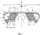
- the figure 1 shows the meridian section of a tire 1 according to a first embodiment, with two symmetrical flexible soles 8 each comprising a rigid anchoring portion 81.
- the tire 1 comprises a crown 2 having two axial ends 21 each extended, radially inwardly, by a sidewall 3 then by a bead 4 intended to come into contact with a rim 5, the assembly delimiting an inner toric cavity 6. It further comprises a carcass reinforcement 7, connecting the two sidewalls 3 to each other by extending in a radially inner portion of the crown 2 and anchored, in each bead 4, to a circumferential reinforcing element 41. Each bead 4 is extended. axially inward by a flexible flange 8 in cantilever comprising a free end I.
- the flexible flanges 8 extending each bead 4 are symmetrical, with respect to an equatorial plane XZ equidistant from the axial ends 21 of the top 2, and structurally identical .
- Each flexible sole 8 comprises an anchoring portion 81 to the bead and a rigid running portion 82, extending axially inwardly from the anchoring portion 81 to the free end I.
- the anchoring portion 81 to the bead structurally extends the rigid current portion 82 and is itself rigid.
- Each flexible sole 8 has an axial width W1, measured between the point J, the most axially outer of the flexible sole 8 and in contact with the bead 4, and the axially inner free end I of the flexible sole 8.
- the running portion 82 of the flexible sole 8 has an average radial thickness T.
- the tire 1 further comprises a supporting structure 9, intended to at least partially take up the nominal load Z applied to the tire mounted on its rim 5 and inflated to its nominal pressure P , formed by supporting elements 91, two by two independent, extending continuously in the inner toric cavity 6, from a radially inner interface of the crown to the flexible sole 8, so that, when the tire is subjected to a nominal radial load Z, the supporting elements 91, connected to a portion of the tire in contact with the ground, are subjected to compressive buckling and at least part of the supporting elements 9 1, connected to the portion of the tire not in contact with the ground, are in tension.
- the radially inner interface of the top 22 to which the supporting structure 9 is connected comprises two disjoint portions (221, 222), symmetrical by relative to the equatorial plane XZ and structurally identical.
- Each disjoint portion (221, 222) of the radially inner interface of crown 22 has an axial width W2.
- the supporting structure 9 comprises identical wire supporting elements 91 forming, with a radial direction ZZ ', an angle C at most equal to 50 °.
- the radially outer ends 911 of the wire carrier elements 91 are bonded to a radially outer fabric, constituting the radially inner interface of the crown 22, and the radially inner ends 912 of the wire carrier elements 91 are bonded to a radially outer fabric. interior, attached to the flexible sole 8.
- the figure 2 shows the meridian section of a tire according to a second embodiment, with two symmetrical flexible soles 8 each comprising a flexible anchoring portion 81.
- the description of the figure 1 remains valid for the figure 2 .
- the specificity of the second embodiment shown is the anchoring portion 81 extending the rigid running portion 82 of each flexible sole 8.
- the anchoring portion 81 constituted by an extension of the carcass reinforcement 7, has a rigidity K2 lower than the rigidity K1 of the rigid current portion 82.
- the anchoring portion 81 of the flexible sole 8 has an axial width W3, measured between the point J, the most axially outer of the flexible sole 8 and in contact with the bead 4, and the axially outer end K of the portion running 82 of the flexible sole 8.
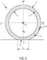
- the figure 3 shows a circumferential section of a tire 1 according to the invention, mounted on a rim 5, in its crushed inflated state, that is to say subjected to a nominal pressure P and a nominal radial load Z.
- the supporting structure 9 is formed by supporting elements 91, two by two independent, extending continuously in the inner toric cavity 6, from a radially inner interface (not shown) of the top 2 to the flexible sole (not shown).
- the tire 1, subjected to a nominal radial load Z is in contact with a flat ground via a contact surface A, having a circumferential length X A.
- the supporting elements 91, connected to a portion of the tire in contact with the ground are subjected to compressive buckling and at least part of the supporting elements 91, connected to the portion of the tire not in contact with the ground, are in tension. .
- the invention has been more particularly studied for a passenger tire of dimension 255/35 ZR 19.
- a reference tire R has thus been compared to a tire A according to the second embodiment of the invention, presented in figure 2 , with two symmetrical flexible soles each comprising a flexible anchoring portion.
- Each flexible sole has an axial width W1 equal to 80 mm for an axial width S of the tire equal to 225 mm, that is to say equal to 0.35 times the axial width S, and an average radial thickness T equal to 5 mm .
- the anchoring portion of each flexible sole has an axial width W3 equal to 20 mm, that is to say equal to 0.25 times the axial width W1.
- Each radially inner interface portion of the crown has an axial width W2 equal to 60 mm for an axial width S of the tire equal to 225 mm, that is to say equal to 0.27 times the axial width S.
- the supporting structure is made up of identical wire or guy load-bearing elements in PET, with a density of 85,000 wires / m 2 .
- Table 1 summarizes the differences in characteristics between the tire A according to the invention and the reference tire R: Table 1 Characteristics Differences in characteristics between invention A and reference R Rolling resistance -20% Radial stiffness K ZZ + 10% Transverse stiffness K YY + 70%
Landscapes
- Engineering & Computer Science (AREA)
- Mechanical Engineering (AREA)
- Tires In General (AREA)
Claims (15)
- Reifen (1) für einen Personenkraftwagen mit einer axialen Breite S, der dazu bestimmt ist, auf einen Nenndruck (P) aufgepumpt und einer Nennlast (Z) ausgesetzt zu werden, beinhaltend:- einen Scheitel (2), der zwei axiale Enden (21) aufweist, die jeweils durch eine Flanke (3) und dann durch einen Wulst (4), der dazu bestimmt ist, mit einer Felge (5) in Kontakt zu kommen, radial nach innen verlängert werden, wobei die Einheit, die aus dem Scheitel (2), den zwei Flanken (3) und den zwei Wulsten (4) besteht, einen torischen Innenhohlraum (6) abgrenzt,- eine Karkassenbewehrung (7), die die zwei Flanken (3) miteinander verbindet, indem sie sich in einem radial innen liegenden Abschnitt des Scheitels (2) erstreckt, und die in jedem Wulst (4) an einem verstärkenden Umlaufelement (41) verankert ist,dadurch gekennzeichnet, dass mindestens ein Wulst (4) durch eine freitragende flexible Sohle (8), die ein freies Ende (I) beinhaltet, axial nach innen verlängert wird, dass die flexible Sohle (8) einen Abschnitt zur Verankerung (81) an dem Wulst (4) und einen steifen durchlaufenden Abschnitt (82), der sich von dem Verankerungsabschnitt (81) bis zu dem freien Ende (I) axial nach innen erstreckt, beinhaltet, dass der Reifen (1) eine Tragstruktur (9) beinhaltet, die dazu bestimmt ist, die Nennlast (Z), die auf den Reifen (1), der auf seiner Felge (5) montiert und auf seinen Nenndruck (P) aufgepumpt ist, ausgeübt wird, mindestens teilweise aufzunehmen, und dass die Tragstruktur (9) aus Tragelementen (91) besteht, die paarweise unabhängig sind und sich in dem torischen Innenhohlraum (6) von einer radial innen liegenden Schnittstelle des Scheitels (22) bis zu der flexiblen Sohle (8) kontinuierlich erstrecken, sodass, wenn der Reifen (1) einer Nennlast (Z) ausgesetzt wird, die Tragelemente (91), die mit einem Abschnitt des Reifens (1), der mit dem Boden in Kontakt ist, verbunden sind, einer Knickbeanspruchung durch Druck ausgesetzt werden und mindestens ein Teil der Tragelemente (91), die mit dem Abschnitt des Reifens (1), der nicht mit dem Boden in Kontakt ist, verbunden sind, unter Spannung stehen.
- Reifen (1) nach Anspruch 1, wobei jeder Wulst (4) durch eine flexible Sohle (8) axial nach innen verlängert wird.
- Reifen (1) nach Anspruch 2, wobei die flexiblen Sohlen (8) in Bezug auf eine Äquatorialebene (XZ), die von den axialen Enden (21) des Scheitels (2) gleich weit entfernt ist, symmetrisch sind.
- Reifen (1) nach Anspruch 3, wobei die symmetrischen flexiblen Sohlen (8) strukturell identisch sind.
- Reifen (1) nach einem der Ansprüche 2 bis 4, wobei jede flexible Sohle (8) eine axiale Breite W1 aufweist, die mindestens gleich dem 0,05-fachen der axialen Breite S des Reifens (1) ist.
- Reifen (1) nach einem der Ansprüche 2 bis 5, wobei jede flexible Sohle (8) eine axiale Breite W1 aufweist, die höchstens gleich dem 0,4-fachen der axialen Breite S des Reifens (1) ist.
- Reifen (1) nach einem der Ansprüche 2 bis 6, wobei der Verankerungsabschnitt (81) jeder flexiblen Sohle (8) eine Steifigkeit K1 aufweist, die höchstens gleich der Steifigkeit K2 des durchlaufenden Abschnitts (82) der flexiblen Sohle (8) ist.
- Reifen (1) nach Anspruch 7, wobei der Verankerungsabschnitt (81) jeder flexiblen Sohle (8) eine axiale Breite W3 aufweist, die höchstens gleich dem 0,85-fachen der axialen Breite W1 der flexiblen Sohle (8) ist, wobei die axiale Breite W3 der axiale Abstand ist, der zwischen dem axial am weitesten außen liegenden Punkt (J) jeder flexiblen Sohle (8), der mit jedem Wulst (4) in Kontakt ist, und dem axial außen liegenden Ende (K) des durchlaufenden Abschnitts (82) jeder flexiblen Sohle (8) gemessen wird.
- Reifen (1) nach einem der Ansprüche 1 bis 8, wobei die radial innen liegende Schnittstelle des Scheitels (22), mit der die Tragstruktur (9) verbunden ist, zwei getrennte Abschnitte (221, 222) beinhaltet.
- Reifen (1) nach Anspruch 9, wobei die zwei getrennten Abschnitte (221, 222) der radial innen liegenden Schnittstelle des Scheitels (22) in Bezug auf eine Äquatorialebene (XZ), die von den axialen Enden (21) des Scheitels (2) gleich weit entfernt ist, symmetrisch sind.
- Reifen (1) nach Anspruch 10, wobei die zwei getrennten und symmetrischen Abschnitte (221, 222) der radial innen liegenden Schnittstelle des Scheitels (22) strukturell identisch sind.
- Reifen (1) nach einem der Ansprüche 9 bis 11, wobei jeder getrennte Abschnitt (221, 222) der radial innen liegenden Schnittstelle des Scheitels (22) eine axiale Breite W2 aufweist, die mindestens gleich dem 0,05-fachen der axialen Breite S des Reifens (1) ist.
- Reifen (1) nach einem der Ansprüche 9 bis 12, wobei jeder getrennte Abschnitt (221, 222) der radial innen liegenden Schnittstelle des Scheitels (22) eine axiale Breite W2 aufweist, die höchstens gleich dem 0,4-fachen der axialen Breite S des Reifens (1) ist.
- Reifen (1) nach einem der vorhergehenden Ansprüche, wobei die Tragstruktur (9) identische Tragelemente aus Draht (91) beinhaltet, wobei die Tragelemente aus Draht (91) mit einer radialen Richtung (ZZ') einen Winkel (C) von höchstens gleich 50° bilden.
- Reifen (1) nach dem vorhergehenden Anspruch, wobei die Tragstruktur (9) aus identischen Tragelementen aus Draht (91) besteht, deren radial außen liegende Enden (911) mit einem radial außen liegenden Gewebe, das die radial innen liegende Schnittstelle des Scheitels (22) bildet, verbunden sind und deren radial innen liegende Enden (912) mit einem radial innen liegenden Gewebe, das an der flexiblen Sohle (8) befestigt ist, verbunden sind.
Applications Claiming Priority (2)
| Application Number | Priority Date | Filing Date | Title |
|---|---|---|---|
| FR1760434 | 2017-11-07 | ||
| PCT/FR2018/052711 WO2019092343A1 (fr) | 2017-11-07 | 2018-11-05 | Pneumatique pour vehicule de tourisme |
Publications (2)
| Publication Number | Publication Date |
|---|---|
| EP3707016A1 EP3707016A1 (de) | 2020-09-16 |
| EP3707016B1 true EP3707016B1 (de) | 2021-07-14 |
Family
ID=60515701
Family Applications (1)
| Application Number | Title | Priority Date | Filing Date |
|---|---|---|---|
| EP18808445.3A Active EP3707016B1 (de) | 2017-11-07 | 2018-11-05 | Reifen für personenkraftwagen |
Country Status (2)
| Country | Link |
|---|---|
| EP (1) | EP3707016B1 (de) |
| WO (1) | WO2019092343A1 (de) |
Families Citing this family (8)
| Publication number | Priority date | Publication date | Assignee | Title |
|---|---|---|---|---|
| EP3724004B1 (de) * | 2017-12-11 | 2022-07-20 | Compagnie Generale Des Etablissements Michelin | Fahrzeugluftreifen mit verstärkungsstruktur im unteren torischen hohlraum |
| FR3098440B1 (fr) | 2019-07-11 | 2021-07-16 | Michelin & Cie | Assemblage comprenant un tissu déformable plastiquement et une structure porteuse |
| FR3098441B1 (fr) | 2019-07-11 | 2021-07-16 | Michelin & Cie | Assemblage comprenant un tissu partiellement rompable et une structure porteuse |
| FR3102082B1 (fr) | 2019-10-18 | 2021-10-22 | Michelin & Cie | Assemblage comprenant un tissu à âme fusible et une structure porteuse |
| FR3103732B1 (fr) | 2019-11-29 | 2023-03-31 | Michelin & Cie | Assemblage comprenant une structure porteuse adaptable |
| FR3103733B1 (fr) | 2019-11-29 | 2022-08-19 | Michelin & Cie | Assemblage comprenant une structure porteuse adaptable |
| FR3112311B1 (fr) | 2020-07-08 | 2022-06-24 | Michelin & Cie | Pneumatique pour véhicule de tourisme |
| FR3127154B1 (fr) * | 2021-09-22 | 2023-10-06 | Michelin & Cie | Enceinte de vulcanisation de pneumatique |
Family Cites Families (4)
| Publication number | Priority date | Publication date | Assignee | Title |
|---|---|---|---|---|
| US3010504A (en) * | 1960-06-06 | 1961-11-28 | Gen Motors Corp | Tire construction |
| US5568830A (en) * | 1995-04-03 | 1996-10-29 | Polsinelli; Vincenzo V. | Pneumatic tire and rim |
| FR2971733B1 (fr) * | 2011-02-17 | 2013-02-22 | Michelin Soc Tech | Pneumatique ayant des bourrelets perfectionnes. |
| FR3038543B1 (fr) | 2015-07-06 | 2017-07-21 | Michelin & Cie | Dispositif de type pneumatique pour vehicule |
-
2018
- 2018-11-05 EP EP18808445.3A patent/EP3707016B1/de active Active
- 2018-11-05 WO PCT/FR2018/052711 patent/WO2019092343A1/fr not_active Ceased
Also Published As
| Publication number | Publication date |
|---|---|
| EP3707016A1 (de) | 2020-09-16 |
| WO2019092343A1 (fr) | 2019-05-16 |
Similar Documents
| Publication | Publication Date | Title |
|---|---|---|
| EP3707016B1 (de) | Reifen für personenkraftwagen | |
| EP3319814B1 (de) | Reifenartige vorrichtung für ein fahrzeug | |
| EP3724004B1 (de) | Fahrzeugluftreifen mit verstärkungsstruktur im unteren torischen hohlraum | |
| EP3247574B1 (de) | Reifenartige vorrichtung für ein fahrzeug | |
| FR3089870A1 (fr) | Pneumatique pour véhicule comprenant une structure de rigidification. | |
| EP3247575B1 (de) | Reifenartige vorrichtung für ein fahrzeug | |
| EP3083288B1 (de) | Adapter für eine walzenanordnung und walzenanordnung damit | |
| EP3484726B1 (de) | Reifen mit wulstbereich mit reduziertem gewicht | |
| EP3294576B1 (de) | Adapter für eine rollende anordnung und rollende anordnung damit | |
| WO2020079366A1 (fr) | Pneumatique pour vehicule avec structure porteuse | |
| WO2004058516A1 (fr) | Pneumatique a mobilite etendue avec flancs a rigidite variable | |
| WO2016015964A1 (fr) | Armature de sommet de pneumatique pour avion | |
| EP2931538A1 (de) | Reifenwulst für schwerlastfahrzeug | |
| EP3490814A1 (de) | Reifenartige vorrichtung für ein fahrzeug | |
| EP3823846B1 (de) | Reifen mit gewichtsreduziertem wulstbereich | |
| EP1789266B1 (de) | Reifen mit erweiterter mobilität, der mehrere sehr niedrige ankerbereiche aufweist | |
| EP3490813A1 (de) | Reifenartige vorrichtung für ein fahrzeug | |
| EP3642052B1 (de) | Reifenartige vorrichtung für ein fahrzeug | |
| WO2020094979A1 (fr) | Dispositif de type pneumatique à éléments filaires souples pour véhicule | |
| FR3112311A1 (fr) | Pneumatique pour véhicule de tourisme | |
| FR3121868A1 (fr) | Architecture optimisée d’un pneumatique de type Génie Civil |
Legal Events
| Date | Code | Title | Description |
|---|---|---|---|
| STAA | Information on the status of an ep patent application or granted ep patent |
Free format text: STATUS: UNKNOWN |
|
| STAA | Information on the status of an ep patent application or granted ep patent |
Free format text: STATUS: THE INTERNATIONAL PUBLICATION HAS BEEN MADE |
|
| PUAI | Public reference made under article 153(3) epc to a published international application that has entered the european phase |
Free format text: ORIGINAL CODE: 0009012 |
|
| STAA | Information on the status of an ep patent application or granted ep patent |
Free format text: STATUS: REQUEST FOR EXAMINATION WAS MADE |
|
| 17P | Request for examination filed |
Effective date: 20200608 |
|
| AK | Designated contracting states |
Kind code of ref document: A1 Designated state(s): AL AT BE BG CH CY CZ DE DK EE ES FI FR GB GR HR HU IE IS IT LI LT LU LV MC MK MT NL NO PL PT RO RS SE SI SK SM TR |
|
| AX | Request for extension of the european patent |
Extension state: BA ME |
|
| DAV | Request for validation of the european patent (deleted) | ||
| DAX | Request for extension of the european patent (deleted) | ||
| REG | Reference to a national code |
Ref country code: DE Ref legal event code: R079 Ref document number: 602018020213 Country of ref document: DE Free format text: PREVIOUS MAIN CLASS: B60C0019000000 Ipc: B60C0003040000 |
|
| GRAP | Despatch of communication of intention to grant a patent |
Free format text: ORIGINAL CODE: EPIDOSNIGR1 |
|
| STAA | Information on the status of an ep patent application or granted ep patent |
Free format text: STATUS: GRANT OF PATENT IS INTENDED |
|
| RIC1 | Information provided on ipc code assigned before grant |
Ipc: B60C 3/04 20060101AFI20210325BHEP Ipc: B60C 9/02 20060101ALI20210325BHEP Ipc: B60C 9/18 20060101ALI20210325BHEP Ipc: B60C 13/00 20060101ALI20210325BHEP Ipc: B60C 15/02 20060101ALI20210325BHEP Ipc: B60C 15/024 20060101ALI20210325BHEP Ipc: B60C 19/00 20060101ALI20210325BHEP |
|
| INTG | Intention to grant announced |
Effective date: 20210414 |
|
| GRAS | Grant fee paid |
Free format text: ORIGINAL CODE: EPIDOSNIGR3 |
|
| GRAA | (expected) grant |
Free format text: ORIGINAL CODE: 0009210 |
|
| STAA | Information on the status of an ep patent application or granted ep patent |
Free format text: STATUS: THE PATENT HAS BEEN GRANTED |
|
| AK | Designated contracting states |
Kind code of ref document: B1 Designated state(s): AL AT BE BG CH CY CZ DE DK EE ES FI FR GB GR HR HU IE IS IT LI LT LU LV MC MK MT NL NO PL PT RO RS SE SI SK SM TR |
|
| REG | Reference to a national code |
Ref country code: GB Ref legal event code: FG4D Free format text: NOT ENGLISH |
|
| REG | Reference to a national code |
Ref country code: IE Ref legal event code: FG4D Free format text: LANGUAGE OF EP DOCUMENT: FRENCH |
|
| REG | Reference to a national code |
Ref country code: DE Ref legal event code: R096 Ref document number: 602018020213 Country of ref document: DE |
|
| REG | Reference to a national code |
Ref country code: AT Ref legal event code: REF Ref document number: 1410343 Country of ref document: AT Kind code of ref document: T Effective date: 20210815 |
|
| REG | Reference to a national code |
Ref country code: LT Ref legal event code: MG9D |
|
| REG | Reference to a national code |
Ref country code: NL Ref legal event code: MP Effective date: 20210714 |
|
| REG | Reference to a national code |
Ref country code: AT Ref legal event code: MK05 Ref document number: 1410343 Country of ref document: AT Kind code of ref document: T Effective date: 20210714 |
|
| PG25 | Lapsed in a contracting state [announced via postgrant information from national office to epo] |
Ref country code: ES Free format text: LAPSE BECAUSE OF FAILURE TO SUBMIT A TRANSLATION OF THE DESCRIPTION OR TO PAY THE FEE WITHIN THE PRESCRIBED TIME-LIMIT Effective date: 20210714 Ref country code: FI Free format text: LAPSE BECAUSE OF FAILURE TO SUBMIT A TRANSLATION OF THE DESCRIPTION OR TO PAY THE FEE WITHIN THE PRESCRIBED TIME-LIMIT Effective date: 20210714 Ref country code: SE Free format text: LAPSE BECAUSE OF FAILURE TO SUBMIT A TRANSLATION OF THE DESCRIPTION OR TO PAY THE FEE WITHIN THE PRESCRIBED TIME-LIMIT Effective date: 20210714 Ref country code: RS Free format text: LAPSE BECAUSE OF FAILURE TO SUBMIT A TRANSLATION OF THE DESCRIPTION OR TO PAY THE FEE WITHIN THE PRESCRIBED TIME-LIMIT Effective date: 20210714 Ref country code: AT Free format text: LAPSE BECAUSE OF FAILURE TO SUBMIT A TRANSLATION OF THE DESCRIPTION OR TO PAY THE FEE WITHIN THE PRESCRIBED TIME-LIMIT Effective date: 20210714 Ref country code: BG Free format text: LAPSE BECAUSE OF FAILURE TO SUBMIT A TRANSLATION OF THE DESCRIPTION OR TO PAY THE FEE WITHIN THE PRESCRIBED TIME-LIMIT Effective date: 20211014 Ref country code: LT Free format text: LAPSE BECAUSE OF FAILURE TO SUBMIT A TRANSLATION OF THE DESCRIPTION OR TO PAY THE FEE WITHIN THE PRESCRIBED TIME-LIMIT Effective date: 20210714 Ref country code: PT Free format text: LAPSE BECAUSE OF FAILURE TO SUBMIT A TRANSLATION OF THE DESCRIPTION OR TO PAY THE FEE WITHIN THE PRESCRIBED TIME-LIMIT Effective date: 20211115 Ref country code: NL Free format text: LAPSE BECAUSE OF FAILURE TO SUBMIT A TRANSLATION OF THE DESCRIPTION OR TO PAY THE FEE WITHIN THE PRESCRIBED TIME-LIMIT Effective date: 20210714 Ref country code: NO Free format text: LAPSE BECAUSE OF FAILURE TO SUBMIT A TRANSLATION OF THE DESCRIPTION OR TO PAY THE FEE WITHIN THE PRESCRIBED TIME-LIMIT Effective date: 20211014 Ref country code: HR Free format text: LAPSE BECAUSE OF FAILURE TO SUBMIT A TRANSLATION OF THE DESCRIPTION OR TO PAY THE FEE WITHIN THE PRESCRIBED TIME-LIMIT Effective date: 20210714 |
|
| PG25 | Lapsed in a contracting state [announced via postgrant information from national office to epo] |
Ref country code: PL Free format text: LAPSE BECAUSE OF FAILURE TO SUBMIT A TRANSLATION OF THE DESCRIPTION OR TO PAY THE FEE WITHIN THE PRESCRIBED TIME-LIMIT Effective date: 20210714 Ref country code: LV Free format text: LAPSE BECAUSE OF FAILURE TO SUBMIT A TRANSLATION OF THE DESCRIPTION OR TO PAY THE FEE WITHIN THE PRESCRIBED TIME-LIMIT Effective date: 20210714 Ref country code: GR Free format text: LAPSE BECAUSE OF FAILURE TO SUBMIT A TRANSLATION OF THE DESCRIPTION OR TO PAY THE FEE WITHIN THE PRESCRIBED TIME-LIMIT Effective date: 20211015 |
|
| REG | Reference to a national code |
Ref country code: DE Ref legal event code: R097 Ref document number: 602018020213 Country of ref document: DE |
|
| PG25 | Lapsed in a contracting state [announced via postgrant information from national office to epo] |
Ref country code: DK Free format text: LAPSE BECAUSE OF FAILURE TO SUBMIT A TRANSLATION OF THE DESCRIPTION OR TO PAY THE FEE WITHIN THE PRESCRIBED TIME-LIMIT Effective date: 20210714 |
|
| PLBE | No opposition filed within time limit |
Free format text: ORIGINAL CODE: 0009261 |
|
| STAA | Information on the status of an ep patent application or granted ep patent |
Free format text: STATUS: NO OPPOSITION FILED WITHIN TIME LIMIT |
|
| PG25 | Lapsed in a contracting state [announced via postgrant information from national office to epo] |
Ref country code: SM Free format text: LAPSE BECAUSE OF FAILURE TO SUBMIT A TRANSLATION OF THE DESCRIPTION OR TO PAY THE FEE WITHIN THE PRESCRIBED TIME-LIMIT Effective date: 20210714 Ref country code: SK Free format text: LAPSE BECAUSE OF FAILURE TO SUBMIT A TRANSLATION OF THE DESCRIPTION OR TO PAY THE FEE WITHIN THE PRESCRIBED TIME-LIMIT Effective date: 20210714 Ref country code: RO Free format text: LAPSE BECAUSE OF FAILURE TO SUBMIT A TRANSLATION OF THE DESCRIPTION OR TO PAY THE FEE WITHIN THE PRESCRIBED TIME-LIMIT Effective date: 20210714 Ref country code: EE Free format text: LAPSE BECAUSE OF FAILURE TO SUBMIT A TRANSLATION OF THE DESCRIPTION OR TO PAY THE FEE WITHIN THE PRESCRIBED TIME-LIMIT Effective date: 20210714 Ref country code: CZ Free format text: LAPSE BECAUSE OF FAILURE TO SUBMIT A TRANSLATION OF THE DESCRIPTION OR TO PAY THE FEE WITHIN THE PRESCRIBED TIME-LIMIT Effective date: 20210714 Ref country code: AL Free format text: LAPSE BECAUSE OF FAILURE TO SUBMIT A TRANSLATION OF THE DESCRIPTION OR TO PAY THE FEE WITHIN THE PRESCRIBED TIME-LIMIT Effective date: 20210714 |
|
| 26N | No opposition filed |
Effective date: 20220419 |
|
| PG25 | Lapsed in a contracting state [announced via postgrant information from national office to epo] |
Ref country code: MC Free format text: LAPSE BECAUSE OF FAILURE TO SUBMIT A TRANSLATION OF THE DESCRIPTION OR TO PAY THE FEE WITHIN THE PRESCRIBED TIME-LIMIT Effective date: 20210714 |
|
| REG | Reference to a national code |
Ref country code: CH Ref legal event code: PL |
|
| PG25 | Lapsed in a contracting state [announced via postgrant information from national office to epo] |
Ref country code: LU Free format text: LAPSE BECAUSE OF NON-PAYMENT OF DUE FEES Effective date: 20211105 Ref country code: IT Free format text: LAPSE BECAUSE OF FAILURE TO SUBMIT A TRANSLATION OF THE DESCRIPTION OR TO PAY THE FEE WITHIN THE PRESCRIBED TIME-LIMIT Effective date: 20210714 Ref country code: BE Free format text: LAPSE BECAUSE OF NON-PAYMENT OF DUE FEES Effective date: 20211130 |
|
| REG | Reference to a national code |
Ref country code: BE Ref legal event code: MM Effective date: 20211130 |
|
| PG25 | Lapsed in a contracting state [announced via postgrant information from national office to epo] |
Ref country code: LI Free format text: LAPSE BECAUSE OF NON-PAYMENT OF DUE FEES Effective date: 20211130 Ref country code: CH Free format text: LAPSE BECAUSE OF NON-PAYMENT OF DUE FEES Effective date: 20211130 |
|
| PG25 | Lapsed in a contracting state [announced via postgrant information from national office to epo] |
Ref country code: IE Free format text: LAPSE BECAUSE OF NON-PAYMENT OF DUE FEES Effective date: 20211105 |
|
| PG25 | Lapsed in a contracting state [announced via postgrant information from national office to epo] |
Ref country code: CY Free format text: LAPSE BECAUSE OF FAILURE TO SUBMIT A TRANSLATION OF THE DESCRIPTION OR TO PAY THE FEE WITHIN THE PRESCRIBED TIME-LIMIT Effective date: 20210714 |
|
| GBPC | Gb: european patent ceased through non-payment of renewal fee |
Effective date: 20221105 |
|
| PG25 | Lapsed in a contracting state [announced via postgrant information from national office to epo] |
Ref country code: HU Free format text: LAPSE BECAUSE OF FAILURE TO SUBMIT A TRANSLATION OF THE DESCRIPTION OR TO PAY THE FEE WITHIN THE PRESCRIBED TIME-LIMIT; INVALID AB INITIO Effective date: 20181105 |
|
| PG25 | Lapsed in a contracting state [announced via postgrant information from national office to epo] |
Ref country code: GB Free format text: LAPSE BECAUSE OF NON-PAYMENT OF DUE FEES Effective date: 20221105 |
|
| PG25 | Lapsed in a contracting state [announced via postgrant information from national office to epo] |
Ref country code: MK Free format text: LAPSE BECAUSE OF FAILURE TO SUBMIT A TRANSLATION OF THE DESCRIPTION OR TO PAY THE FEE WITHIN THE PRESCRIBED TIME-LIMIT Effective date: 20210714 |
|
| PG25 | Lapsed in a contracting state [announced via postgrant information from national office to epo] |
Ref country code: TR Free format text: LAPSE BECAUSE OF FAILURE TO SUBMIT A TRANSLATION OF THE DESCRIPTION OR TO PAY THE FEE WITHIN THE PRESCRIBED TIME-LIMIT Effective date: 20210714 |
|
| PG25 | Lapsed in a contracting state [announced via postgrant information from national office to epo] |
Ref country code: MT Free format text: LAPSE BECAUSE OF FAILURE TO SUBMIT A TRANSLATION OF THE DESCRIPTION OR TO PAY THE FEE WITHIN THE PRESCRIBED TIME-LIMIT Effective date: 20210714 |
|
| PGFP | Annual fee paid to national office [announced via postgrant information from national office to epo] |
Ref country code: DE Payment date: 20241121 Year of fee payment: 7 |
|
| PGFP | Annual fee paid to national office [announced via postgrant information from national office to epo] |
Ref country code: FR Payment date: 20241128 Year of fee payment: 7 |