EP3706547B1 - Interface between rotor cage and transition cone for agricultural harvester - Google Patents
Interface between rotor cage and transition cone for agricultural harvester Download PDFInfo
- Publication number
- EP3706547B1 EP3706547B1 EP18815403.3A EP18815403A EP3706547B1 EP 3706547 B1 EP3706547 B1 EP 3706547B1 EP 18815403 A EP18815403 A EP 18815403A EP 3706547 B1 EP3706547 B1 EP 3706547B1
- Authority
- EP
- European Patent Office
- Prior art keywords
- rotor
- cage
- threshing
- edge
- rotor cage
- Prior art date
- Legal status (The legal status is an assumption and is not a legal conclusion. Google has not performed a legal analysis and makes no representation as to the accuracy of the status listed.)
- Active
Links
Images


Classifications
-
- A—HUMAN NECESSITIES
- A01—AGRICULTURE; FORESTRY; ANIMAL HUSBANDRY; HUNTING; TRAPPING; FISHING
- A01F—PROCESSING OF HARVESTED PRODUCE; HAY OR STRAW PRESSES; DEVICES FOR STORING AGRICULTURAL OR HORTICULTURAL PRODUCE
- A01F7/00—Threshing apparatus
- A01F7/02—Threshing apparatus with rotating tools
- A01F7/06—Threshing apparatus with rotating tools with axles in line with the feeding direction ; Axial threshing machines
- A01F7/062—Threshing apparatus with rotating tools with axles in line with the feeding direction ; Axial threshing machines with a rotating cage
-
- A—HUMAN NECESSITIES
- A01—AGRICULTURE; FORESTRY; ANIMAL HUSBANDRY; HUNTING; TRAPPING; FISHING
- A01F—PROCESSING OF HARVESTED PRODUCE; HAY OR STRAW PRESSES; DEVICES FOR STORING AGRICULTURAL OR HORTICULTURAL PRODUCE
- A01F7/00—Threshing apparatus
- A01F7/02—Threshing apparatus with rotating tools
- A01F7/06—Threshing apparatus with rotating tools with axles in line with the feeding direction ; Axial threshing machines
- A01F7/067—Threshing apparatus with rotating tools with axles in line with the feeding direction ; Axial threshing machines with material-flow influencing means
-
- A—HUMAN NECESSITIES
- A01—AGRICULTURE; FORESTRY; ANIMAL HUSBANDRY; HUNTING; TRAPPING; FISHING
- A01F—PROCESSING OF HARVESTED PRODUCE; HAY OR STRAW PRESSES; DEVICES FOR STORING AGRICULTURAL OR HORTICULTURAL PRODUCE
- A01F12/00—Parts or details of threshing apparatus
- A01F12/46—Mechanical grain conveyors
Definitions
- the present invention relates to an interface between a rotor cage and a transition cone for a combine harvester.
- a rotary threshing or separating system of an agricultural combine harvester includes one or more rotors which can extend axially (front to rear) or transversely (side to side) within the body of the combine, and which are partially or fully surrounded by a perforated concave.
- the crop material is threshed and separated by the rotation of the rotor within the concave.
- Coarser non-grain crop material such as stalks and leaves are transported to the rear of the combine and discharged back to the field.
- the separated grain, together with some finer non-grain crop material such as chaff, dust, straw, and other crop residue are discharged through the concaves and fall onto a grain pan where they are transported to the cleaning system.
- the grain and finer non-grain crop material may also fall directly onto the cleaning system itself.
- a transition cone between a feeder housing and the rotor cage.
- the transition cone narrows along its length, from the upstream end to the downstream end of the cone.
- An auger flight operated by the rotor transports the cut crop material through the transition cone, from the feeder housing and to the rotor cage.
- the threshing and separating system 24 generally includes a rotor 40 at least partially enclosed by and rotatable within a corresponding perforated semi-cylindrical rotor cage 42.
- the cut crops are threshed and separated by the rotation of rotor 40 within rotor cage 42, and larger elements, such as stalks, leaves and the like are discharged from the rear of combine 10.
- Smaller elements of crop material including grain and non-grain crop material, including particles lighter than grain, such as chaff, dust and straw, are discharged through perforations of rotor cage 42.
- Rotor 40 is shown in a representative sense in that rotor 40 may be more than one rotor 40 and may be oriented generally in line with the direction of travel of combine 10. Grain that has been separated by threshing and separating assembly 24 falls onto a grain pan and is conveyed toward cleaning system.
- Rotor 40 includes a downstream portion having threshing elements 72, and an upstream portion defining an inlet auger 74 having an auger flight or flights 76.
- the cylindrically shaped rotor cage 42 includes a concave or concaves 78 operating together with threshing elements 72 of rotor 40 to separate grain from crop material.
- a transition cone 80 is connected to rotor cage 42 and defines an infeed to the threshing zone of rotor 40 and rotor cage 42.
- Transition cone 80 has a hollow conical shape including an inner cone surface 82 having a larger diameter at the upstream end 84 thereof and tapering to a smaller diameter at the downstream edge 86 thereof, thereby defining a decreasing inner circumference about the inner surface from upstream end 84 to downstream end 86.
- At least one and typically a plurality of helical or spiral vanes 88 is provided on the inner surface of transition cone 80.
- Inlet auger 74 operates within transition cone 80, and crop material is transferred through transition cone 80 under the force applied by rotating auger flight 76, the directional guidance provided by vanes 88 and the influence supplied by the tapering conical shape of transition cone 80.
- the inlet of the rotor cage 42 experiences high wear due to the tight radial clearance between the rotor cage 42 and the rotor 40.
- What is desired in the art is greater clearance between the rotor 40 and the rotor cage 42 to allow for expansion of the crop material in that region, which would permit the grain to migrate to the outside of the crop material for better separation.
- Simply enlarging the rotor cage is not necessarily possible in all harvesters due to vertical clearance limitations within the harvester.
- Patent publication document EP3117698 is related to an agricultural harvester including a chassis and a threshing and separating system carried by the chassis that is configured for threshing and separating grain from gathered crop material.
- the threshing and separating system includes: a rotor defining a longitudinal axis; a concave at least partially surrounding the rotor; a transition cone defining an infeed to the rotor; and a transition surface connecting the transition cone to the concave and having a conical portion defined about the longitudinal axis and a blended portion connected to the conical portion.
- the blended portion defines a first end connected to the conical portion and a second end distanced from the first end in a lateral direction.
- the blended portion defines a substantially conical shape about the longitudinal axis at the first end and approaches a substantially cylindrical shape about the longitudinal axis toward the second end.
- Patent publication document US2009/143123 is related to an improved threshing and separating mechanism for a combine that includes an elongated rotor mounted for rotation about a rotor axis within a rotor housing on the combine.
- the rotor has a threshing portion and a separating portion.
- the housing has a threshing section and a separating section corresponding to the threshing portion and the separating portion.
- the housing surrounds the rotor and is spaced from the rotor to form an annular space between the rotor and the housing for crop material to flow through in an axial crop flow direction from an inlet end of the housing to an outlet end of the housing.
- a rear portion of the rotor tube includes one or more discharge flights or vanes that are adjustable in height and assist in discharging material through the outlet of the rotor housing. The discharge vanes work in conjunction with the vanes in the top covers of the rotor housing.
- the present invention provides a modified rotor cage having greater clearance between the rotor and the rotor cage, and a modified transition cone for mounting to the modified rotor cage.
- a threshing system of an agricultural harvester comprises a rotor cage surrounding a rotor, a threshing space defined between the rotor cage and the rotor, and a transition cone defining an infeed to said rotor cage and said threshing space, the transition cone mounted to said rotor cage at a location upstream of the rotor cage, as viewed in a direction of crop flow through the threshing system, wherein a mating interface between the rotor cage and the transition cone is curved in three different dimensions of a Cartesian coordinate system for maximizing the threshing space.
- a convex portion of the rotor cage is mounted to a concave portion of the transition cone.
- FIGs. 2-4 depict a threshing and separating system 200 according to the present invention.
- System 200 is similar to system 24 of FIG. 1 , and the primary differences between those systems will be described hereinafter.
- System 200 includes a rotor 240 (shown schematically) at least partially enclosed by and rotatable within a corresponding perforated semi-cylindrical rotor cage 242.
- Transition cone 280 (hereinafter “cone”) is connected to rotor cage 242 (hereinafter “cage”) at a mating interface 206/218.
- Cone 280 defines an infeed to the threshing zone of the rotor 240 and cage 242.
- FIGs. 6-8 depict cage 242.
- Cage 242 has a semi-cylindrical body including a curved portion 202 having a pre-defined constant radius 'R,' and straight portions 204 extending downward from each end of curved portion 202.
- Each straight portion 204 has a defined length 'L.'
- the lengths of straight portions 204 are equal according to this embodiment. The lengths 'L' and radius 'R' can be varied to meet the space requirements for different systems 200.
- a flange 205 extends perpendicularly from the end of each straight portion 204. Each flange 205 extends outwardly in a direction away from longitudinal axis 'A' of system 200. Flanges 205 are provided for bolting to other components of system 200.
- Cage 242 may have a constant wall thickness 't.'
- Downstream edge 208 of cage 242 is curved in the X-Y plane (see FIG. 7 ) along radius 'R,' however, downstream edge 208 is not curved in the X-Z plane (see FIG. 8 ).
- transition cone 280 is connected to upstream edge 206 of cage 242.
- Cone 280 defines an infeed to the threshing zone between rotor 240 and cage 242.
- Transition cone 280 has a curved panel 210.
- a hood may be bolted to a flange 213 at the upstream end 214 of panel 210.
- Flange 213 could be replaced by an edge, if so desired.
- panel 210 of cone 280 is either frusto-conical or semi-frusto-conical and comprises one or more sheets of material. In the axial direction, panel 210 extends between an upstream edge 214, which is adjacent the flange 213, and a downstream edge 218, which is mounted to the cage 242.
- the downstream edge 218 of the cone 280 comprises a top edge 218A and bottom edge 218B.
- the top edge 218A of the cone 280 is curved to compliment and mate with upstream edge 206 of cage 242.
- Edge 218A appears concave as viewed from above. More particularly, edge 218A is also curved as viewed in the X-Y plane and has radius 'R' like cage 242.
- Downstream edge 218A is also curved as viewed in an X-Z plane and has radius 'R1' (like cage 242) such that the top center 'P' of the downstream edge 218A protrudes inwardly in an upstream direction with respect to the bottom edge 218B.
- Edge 218B like flange 213, comprises a flange and is curved in the X-Y plane, but not the X-Z plane.
- the top end of panel 210 slopes downward in the downstream direction from the top center upstream end point 'T' of panel 210 to the top center downstream end point 'P.
- the radial distance between the axis A and the top center upstream end point 'T' of panel 210 is greater than the radial distance between the axis A and the top center downstream end point 'P.
- the top end of panel 210 which decreases in diameter in the downstream direction, acts as a funnel in the downstream direction to channel the crop mat to the threshing zone between rotor 240 and cage 242.
- the top center of panel 210 slopes downwardly in the downstream direction (i.e., toward axis A) to only a limited extent so as to create a funnel so that the crop mat passes from the hood (not shown) to the threshing zone, without sacrificing (i.e., without minimizing) the vertical clearance between rotor 240 and rotor cage 242 that constitutes the threshing zone. If the top center downstream end point 'P' at the interface between cone 280 and cage 242 were positioned any lower (i.e., closer to axis A), then sufficient vertical clearance between rotor 240 and cage 242 might not exist.
- curving the edge 218A of cone 208 in the X-Y plane as well as the X-Z plane achieves both goals of (i) funneling the crop mat to the threshing zone, and (ii) maximizing the size of the threshing zone.
- Cone 280 and cage 242 may be composed of steel sheet metal material, for example, or any other material known to those skilled in the art.
- cone 280 and cage 242 By virtue of the geometry of cone 280 and cage 242 it is possible to both funnel crop material to the threshing zone and maintain a large radial clearance between rotor 240 and cage 242.
- the raised rotor cage provides more relief to the crop mat between the rotor and the rotor cage, which allows the crop mat to expand and grain to migrate to the outside of the crop mat for improved separation.
Landscapes
- Life Sciences & Earth Sciences (AREA)
- Environmental Sciences (AREA)
- Threshing Machine Elements (AREA)
Description
- The present invention relates to an interface between a rotor cage and a transition cone for a combine harvester.
- As is described in
U.S. Patent Application No. 2017/0105350 to CNH America LLC a rotary threshing or separating system of an agricultural combine harvester includes one or more rotors which can extend axially (front to rear) or transversely (side to side) within the body of the combine, and which are partially or fully surrounded by a perforated concave. The crop material is threshed and separated by the rotation of the rotor within the concave. Coarser non-grain crop material such as stalks and leaves are transported to the rear of the combine and discharged back to the field. The separated grain, together with some finer non-grain crop material such as chaff, dust, straw, and other crop residue are discharged through the concaves and fall onto a grain pan where they are transported to the cleaning system. Alternatively, the grain and finer non-grain crop material may also fall directly onto the cleaning system itself. - In combines having a rotor operating within a concave formed as a rotor cage, it is known to provide a transition cone between a feeder housing and the rotor cage. The transition cone narrows along its length, from the upstream end to the downstream end of the cone. An auger flight operated by the rotor transports the cut crop material through the transition cone, from the feeder housing and to the rotor cage. It is known to provide helical vanes on the inside surface of the transition cone, to facilitate efficient transport of crop material through the transition cone. During use, the crop material tends to follow along the transition cone vane and is somewhat compressed against the inside surface of the narrowing cone.
- Referring now to the drawings, and more particularly to
FIG. 1 , there is shown a conventional threshing and separatingsystem 24. The threshing and separatingsystem 24 generally includes arotor 40 at least partially enclosed by and rotatable within a corresponding perforatedsemi-cylindrical rotor cage 42. The cut crops are threshed and separated by the rotation ofrotor 40 withinrotor cage 42, and larger elements, such as stalks, leaves and the like are discharged from the rear of combine 10. Smaller elements of crop material including grain and non-grain crop material, including particles lighter than grain, such as chaff, dust and straw, are discharged through perforations ofrotor cage 42.Rotor 40 is shown in a representative sense in thatrotor 40 may be more than onerotor 40 and may be oriented generally in line with the direction of travel of combine 10. Grain that has been separated by threshing and separatingassembly 24 falls onto a grain pan and is conveyed toward cleaning system. -
Rotor 40 includes a downstream portion havingthreshing elements 72, and an upstream portion defining aninlet auger 74 having an auger flight orflights 76. The cylindricallyshaped rotor cage 42 includes a concave or concaves 78 operating together withthreshing elements 72 ofrotor 40 to separate grain from crop material. Atransition cone 80 is connected torotor cage 42 and defines an infeed to the threshing zone ofrotor 40 androtor cage 42.Transition cone 80 has a hollow conical shape including aninner cone surface 82 having a larger diameter at theupstream end 84 thereof and tapering to a smaller diameter at thedownstream edge 86 thereof, thereby defining a decreasing inner circumference about the inner surface fromupstream end 84 todownstream end 86. At least one and typically a plurality of helical orspiral vanes 88 is provided on the inner surface oftransition cone 80. Inletauger 74 operates withintransition cone 80, and crop material is transferred throughtransition cone 80 under the force applied by rotatingauger flight 76, the directional guidance provided byvanes 88 and the influence supplied by the tapering conical shape oftransition cone 80. - In operation, the inlet of the
rotor cage 42 experiences high wear due to the tight radial clearance between therotor cage 42 and therotor 40. What is desired in the art is greater clearance between therotor 40 and therotor cage 42 to allow for expansion of the crop material in that region, which would permit the grain to migrate to the outside of the crop material for better separation. Simply enlarging the rotor cage is not necessarily possible in all harvesters due to vertical clearance limitations within the harvester. - Patent publication document
EP3117698 is related to an agricultural harvester including a chassis and a threshing and separating system carried by the chassis that is configured for threshing and separating grain from gathered crop material. The threshing and separating system includes: a rotor defining a longitudinal axis; a concave at least partially surrounding the rotor; a transition cone defining an infeed to the rotor; and a transition surface connecting the transition cone to the concave and having a conical portion defined about the longitudinal axis and a blended portion connected to the conical portion. The blended portion defines a first end connected to the conical portion and a second end distanced from the first end in a lateral direction. The blended portion defines a substantially conical shape about the longitudinal axis at the first end and approaches a substantially cylindrical shape about the longitudinal axis toward the second end. - Patent publication document
US2009/143123 is related to an improved threshing and separating mechanism for a combine that includes an elongated rotor mounted for rotation about a rotor axis within a rotor housing on the combine. The rotor has a threshing portion and a separating portion. The housing has a threshing section and a separating section corresponding to the threshing portion and the separating portion. The housing surrounds the rotor and is spaced from the rotor to form an annular space between the rotor and the housing for crop material to flow through in an axial crop flow direction from an inlet end of the housing to an outlet end of the housing. A rear portion of the rotor tube includes one or more discharge flights or vanes that are adjustable in height and assist in discharging material through the outlet of the rotor housing. The discharge vanes work in conjunction with the vanes in the top covers of the rotor housing. - The present invention provides a modified rotor cage having greater clearance between the rotor and the rotor cage, and a modified transition cone for mounting to the modified rotor cage.
- More particularly, the invention is related to a threshing system of an agriculturel vehicle in accordance with the appended claims. According to one aspect of the invention, a threshing system of an agricultural harvester comprises a rotor cage surrounding a rotor, a threshing space defined between the rotor cage and the rotor, and a transition cone defining an infeed to said rotor cage and said threshing space, the transition cone mounted to said rotor cage at a location upstream of the rotor cage, as viewed in a direction of crop flow through the threshing system, wherein a mating interface between the rotor cage and the transition cone is curved in three different dimensions of a Cartesian coordinate system for maximizing the threshing space.
- According to another aspect of the invention, as viewed from above the mating interface of the threshing system, a convex portion of the rotor cage is mounted to a concave portion of the transition cone.
- The above-mentioned and other features and advantages of this invention, and the manner of attaining them, will become more apparent and the invention will be better understood by reference to the following description of an embodiment of the invention taken in conjunction with the accompanying drawings, wherein:
-
FIG. 1 is a cross-sectional view of a conventional threshing and separating system in a harvester. -
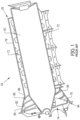
FIG. 2 is an isometric view of a partial threshing and separating system (hereinafter "system") in accordance with an exemplary embodiment of the present invention. -
FIG. 3 is a side elevation view of the system ofFIG. 2 . -
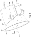
FIG. 4 is a top plan view of the system ofFIG. 2 . -
FIG. 5 is an exploded view showing the rotor cage and transition cone of the system ofFIGs. 2-4 . -
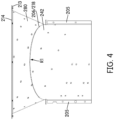
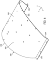
FIG. 6 is an isometric view of the rotor cage ofFIGs. 2-4 . -
FIG. 7 is a front elevation view of the rotor cage ofFIG. 6 . -
FIG. 8 is a top plan view of the rotor cage ofFIG. 6 . - Corresponding reference characters indicate corresponding parts throughout the several views. The exemplification set out herein illustrates an embodiment of the invention, in one form, and such exemplification is not to be construed as limiting the scope of the invention in any manner.
- The terms "grain", "straw" and "tailings" are used principally throughout this specification for convenience but it is to be understood that these terms are not intended to be limiting. "Grain" refers to that part of the crop material which is threshed and separated from the discardable part of the crop material, which is referred to as non-grain crop material, MOG or straw. Incompletely threshed crop material is referred to as "tailings". Also the terms "forward", "rearward", "left" and "right", when used in connection with the agricultural harvester and/or components thereof are usually determined with reference to the direction of forward operative travel of the harvester, but again, they should not be construed as limiting. The terms "longitudinal" and "transverse" are determined with reference to the fore-and-aft direction of the agricultural harvester and are equally not to be construed as limiting.
-
FIGs. 2-4 depict a threshing and separatingsystem 200 according to the present invention.System 200 is similar tosystem 24 ofFIG. 1 , and the primary differences between those systems will be described hereinafter. -
System 200 includes a rotor 240 (shown schematically) at least partially enclosed by and rotatable within a corresponding perforatedsemi-cylindrical rotor cage 242. Transition cone 280 (hereinafter "cone") is connected to rotor cage 242 (hereinafter "cage") at amating interface 206/218.Cone 280 defines an infeed to the threshing zone of therotor 240 andcage 242. -
FIGs. 6-8 depictcage 242.Cage 242 has a semi-cylindrical body including acurved portion 202 having a pre-defined constant radius 'R,' andstraight portions 204 extending downward from each end ofcurved portion 202. Eachstraight portion 204 has a defined length 'L.' The lengths ofstraight portions 204 are equal according to this embodiment. The lengths 'L' and radius 'R' can be varied to meet the space requirements fordifferent systems 200. Aflange 205 extends perpendicularly from the end of eachstraight portion 204. Eachflange 205 extends outwardly in a direction away from longitudinal axis 'A' ofsystem 200.Flanges 205 are provided for bolting to other components ofsystem 200.Cage 242 may have a constant wall thickness 't.' -
Upstream edge 206 ofcage 242, which mates withcone 280 by welds or fasteners (for example), is three dimensional and extends in three different directions. More particularly,upstream edge 206 is curved as viewed in a Y-Z plane (seeFIG. 6 ) of an X-Y-Z Cartesian coordinate system.Upstream edge 206 is convexly curved as viewed in an X-Z plane (seeFIG. 8 ) such that the top center of theupstream edge 206 at point 'V' protrudes outwardly in an upstream direction beyondstraight portions 204 andflanges 205.Upstream edge 206 is also curved as viewed in the X-Y plane (seeFIG. 7 ) along radius 'R.' Radius R1 ofupstream edge 206 in the X-Z plane is tailored to compliment the radius ofedge 218 ofcone 280. -
Downstream edge 208 ofcage 242 is curved in the X-Y plane (seeFIG. 7 ) along radius 'R,' however,downstream edge 208 is not curved in the X-Z plane (seeFIG. 8 ). - As best shown in
FIG. 5 ,transition cone 280 is connected toupstream edge 206 ofcage 242.Cone 280 defines an infeed to the threshing zone betweenrotor 240 andcage 242.Transition cone 280 has acurved panel 210. A hood may be bolted to aflange 213 at theupstream end 214 ofpanel 210.Flange 213, which is provided at (or mounted to) anupstream edge 214 ofpanel 210, protrudes outwardly in a direction away from axis A, and is curved in the X-Y plane, but not the X-Z plane.Flange 213 could be replaced by an edge, if so desired. - Referring now to
panel 210 ofcone 280,panel 210 is either frusto-conical or semi-frusto-conical and comprises one or more sheets of material. In the axial direction,panel 210 extends between anupstream edge 214, which is adjacent theflange 213, and adownstream edge 218, which is mounted to thecage 242. - The
downstream edge 218 of thecone 280 comprises atop edge 218A andbottom edge 218B. Thetop edge 218A of thecone 280 is curved to compliment and mate withupstream edge 206 ofcage 242.Edge 218A appears concave as viewed from above. More particularly,edge 218A is also curved as viewed in the X-Y plane and has radius 'R' likecage 242.Downstream edge 218A is also curved as viewed in an X-Z plane and has radius 'R1' (like cage 242) such that the top center 'P' of thedownstream edge 218A protrudes inwardly in an upstream direction with respect to thebottom edge 218B.Edge 218B, likeflange 213, comprises a flange and is curved in the X-Y plane, but not the X-Z plane. - The top end of
panel 210 slopes downward in the downstream direction from the top center upstream end point 'T' ofpanel 210 to the top center downstream end point 'P.' Stated differently, the radial distance between the axis A and the top center upstream end point 'T' ofpanel 210 is greater than the radial distance between the axis A and the top center downstream end point 'P.' The top end ofpanel 210, which decreases in diameter in the downstream direction, acts as a funnel in the downstream direction to channel the crop mat to the threshing zone betweenrotor 240 andcage 242. - The top center of
panel 210 slopes downwardly in the downstream direction (i.e., toward axis A) to only a limited extent so as to create a funnel so that the crop mat passes from the hood (not shown) to the threshing zone, without sacrificing (i.e., without minimizing) the vertical clearance betweenrotor 240 androtor cage 242 that constitutes the threshing zone. If the top center downstream end point 'P' at the interface betweencone 280 andcage 242 were positioned any lower (i.e., closer to axis A), then sufficient vertical clearance betweenrotor 240 andcage 242 might not exist. It was discovered that curving theedge 218A ofcone 208 in the X-Y plane as well as the X-Z plane achieves both goals of (i) funneling the crop mat to the threshing zone, and (ii) maximizing the size of the threshing zone. -
Cone 280 andcage 242 may be composed of steel sheet metal material, for example, or any other material known to those skilled in the art. - By virtue of the geometry of
cone 280 andcage 242 it is possible to both funnel crop material to the threshing zone and maintain a large radial clearance betweenrotor 240 andcage 242. The raised rotor cage provides more relief to the crop mat between the rotor and the rotor cage, which allows the crop mat to expand and grain to migrate to the outside of the crop mat for improved separation. - While this invention has been described with respect to at least one embodiment, the present invention can be further modified within the scope of the invention as defined in the appended claims.
- This application is therefore intended to cover any variations, uses, or adaptations of the invention using its general principles. Further, this application is intended to cover such departures from the present disclosure as come within known or customary practice in the art to which this invention pertains and which fall within the limits of the appended claims.
Claims (7)
- A threshing system of an agricultural harvester comprising:a rotor (240), and a rotor cage (242) surrounding the rotor (240),a threshing space defined between the rotor cage (242) and the rotor (240), anda transition cone (280) defining an infeed to said rotor cage (242) and said threshing space, the transition cone mounted to said rotor cage at a location upstream of the rotor cage, as viewed in a direction of crop flow through the threshing system,wherein a mating interface between the rotor cage and the transition cone is curved in three different dimensions of a Cartesian coordinate system:characterised in that- the transition cone (280) comprises an upstream edge (214) and a downstream edge (218), as viewed in a direction of crop flow through the threshing system, the downstream edge comprising a curved top edge (218A) and a bottom edge (218B), as viewed in the bottom-to-top direction of the rotor cage (242),- the mating interface comprises said top edge (218A) of the transition cone (208) that is mated to an upstream edge (206) of the rotor cage (242),- the top edge (218A) appears concave when viewed from above and the top center (P) of the top edge (218A) protrudes inwardly in an upstream direction with respect to the bottom edge (218B), for maximizing the threshing space.
- The threshing system of claim 1, wherein the curved top edge (218A) of the transition cone (280) is abutted with the upstream edge (206) of the rotor cage (242) to form the mating interface.
- The threshing system of claim 1, wherein the rotor cage (242) includes a lower mounting surface (205) for mounting to the threshing system, and the upstream edge (206) of the rotor cage protrudes in an upstream direction beyond the lower mounting surface.
- The threshing system of claim 1, wherein the rotor (240) comprises a downstream portion having threshing elements, and an upstream portion having an inlet auger including an auger flight.
- The threshing system of claim 4, wherein the auger flight is surrounded by the transition cone.
- The threshing system of claim 4, wherein the threshing elements are surrounded by the rotor cage (242).
- The threshing system of claim 1, wherein the cage (242) is at least partially cylindrical and the transition cone (280) is at least partially conical, and wherein the cage (242) includes a cylindrical portion (202) and straight leg portions (204) extending downward from each end of the cylindrical portion.
Applications Claiming Priority (2)
| Application Number | Priority Date | Filing Date | Title |
|---|---|---|---|
| US15/806,573 US10694677B2 (en) | 2017-11-08 | 2017-11-08 | Rotor cage to transition cone interface for agricultural harvester |
| PCT/US2018/059898 WO2019094644A1 (en) | 2017-11-08 | 2018-11-08 | Rotor cage to transition cone interface for agricultural harvester |
Publications (2)
| Publication Number | Publication Date |
|---|---|
| EP3706547A1 EP3706547A1 (en) | 2020-09-16 |
| EP3706547B1 true EP3706547B1 (en) | 2024-04-24 |
Family
ID=64650493
Family Applications (1)
| Application Number | Title | Priority Date | Filing Date |
|---|---|---|---|
| EP18815403.3A Active EP3706547B1 (en) | 2017-11-08 | 2018-11-08 | Interface between rotor cage and transition cone for agricultural harvester |
Country Status (4)
| Country | Link |
|---|---|
| US (1) | US10694677B2 (en) |
| EP (1) | EP3706547B1 (en) |
| AR (1) | AR113427A1 (en) |
| WO (1) | WO2019094644A1 (en) |
Families Citing this family (1)
| Publication number | Priority date | Publication date | Assignee | Title |
|---|---|---|---|---|
| US11812701B2 (en) * | 2018-03-15 | 2023-11-14 | Cnh Industrial America Llc | Tangential feeding to a threshing rotor |
Family Cites Families (22)
| Publication number | Priority date | Publication date | Assignee | Title |
|---|---|---|---|---|
| US2493105A (en) * | 1946-02-23 | 1950-01-03 | Bessie Bunting | Combination grain-feeding and threshing means for harvesters |
| US3464419A (en) * | 1966-10-31 | 1969-09-02 | Int Harvester Co | End feeding arrangement |
| US3616800A (en) * | 1969-01-09 | 1971-11-02 | Sperry Rand Corp | Axial flow type combine with a discharge conveyor |
| US3943939A (en) | 1975-03-25 | 1976-03-16 | Sperry Rand Corporation | Combine with adjustable feed plate |
| US4087953A (en) | 1976-10-28 | 1978-05-09 | Deere & Company | Combine crop feeding system |
| US4159023A (en) | 1977-08-02 | 1979-06-26 | Sperry Rand Corporation | Infeed means for axial flow combine |
| DE2830162A1 (en) * | 1978-07-08 | 1980-01-17 | Deere & Co | Axial, threshing and separating device for combine harvesters |
| CA1086174A (en) | 1978-10-31 | 1980-09-23 | White Motor Corporation Of Canada Limited | Axial flow combine with improved inlet transition area |
| US4291709A (en) | 1980-07-02 | 1981-09-29 | Sperry Corporation | Infeed geometry |
| US4665929A (en) | 1986-07-21 | 1987-05-19 | Helm William N | Axial flow combine harvester feed plate |
| US4900290A (en) * | 1988-08-24 | 1990-02-13 | J. I. Case Company | Crop delivery system for an axial-flow combine |
| US5257959A (en) * | 1991-03-21 | 1993-11-02 | Case Corporation | Door assembly for an axial-flow combine |
| US5145462A (en) * | 1991-06-10 | 1992-09-08 | Case Corporation | Infeed assembly for an axial-flow combine |
| US5344367A (en) | 1993-03-31 | 1994-09-06 | Deere & Company | Infeed plate for an axial agricultural combine |
| CA2232330C (en) | 1998-03-17 | 1999-06-15 | Marlin Johnson | Impeller blade for the rotor of an axial flow combine harvester |
| GB0710994D0 (en) | 2007-06-08 | 2007-07-18 | Agco Do Brasil Com E Ind Stria | Combines |
| GB0710995D0 (en) * | 2007-06-08 | 2007-07-18 | Agco Do Brasil Com E Ind Stria | Combines |
| US7717777B2 (en) | 2007-11-29 | 2010-05-18 | Deere & Company | Adjustable rear rotor discharge flights |
| BR212016010382Y1 (en) | 2013-11-25 | 2019-10-01 | Agco Corporation | Arrangement of shovels on a combine harvester processor |
| US9807937B2 (en) | 2015-07-16 | 2017-11-07 | Cnh Industrial America Llc | Agricultural harvester with improved rotor transition geometry |
| BR102016023877B1 (en) | 2015-10-16 | 2021-09-14 | Cnh Industrial America Llc | AGRICULTURAL HARVEST |
| US10420285B2 (en) * | 2017-06-16 | 2019-09-24 | Cnh Industrial America Llc | Transition device for a combine threshing system |
-
2017
- 2017-11-08 US US15/806,573 patent/US10694677B2/en active Active
-
2018
- 2018-11-06 AR ARP180103230A patent/AR113427A1/en active IP Right Grant
- 2018-11-08 EP EP18815403.3A patent/EP3706547B1/en active Active
- 2018-11-08 WO PCT/US2018/059898 patent/WO2019094644A1/en not_active Ceased
Also Published As
| Publication number | Publication date |
|---|---|
| WO2019094644A1 (en) | 2019-05-16 |
| US10694677B2 (en) | 2020-06-30 |
| US20190133041A1 (en) | 2019-05-09 |
| AR113427A1 (en) | 2020-04-29 |
| EP3706547A1 (en) | 2020-09-16 |
Similar Documents
| Publication | Publication Date | Title |
|---|---|---|
| EP3117698B1 (en) | Agricultural harvester with improved rotor transition geometry | |
| US7749054B2 (en) | Modular separator element for a threshing system | |
| EP2298063B1 (en) | Threshing system | |
| EP3466243B1 (en) | Segmented fan housing for cleaning system of combine harvester | |
| US8608534B1 (en) | Rolled secondary cut off in air distribution system of a combine harvester | |
| US11083136B2 (en) | Tapered vane for agricultural harvester transition cone | |
| EP3818811B1 (en) | Agricultural harvester including a threshing drum with rasp bars having crop egress gaps | |
| EP2674024A1 (en) | Combine varying dimensional vane threshing system | |
| EP3706547B1 (en) | Interface between rotor cage and transition cone for agricultural harvester | |
| US20200120875A1 (en) | Adjustable vanes for use in a cylindrical rotor cage of an agricultural harvester | |
| US10420285B2 (en) | Transition device for a combine threshing system | |
| EP3261427B1 (en) | Crop engaging element for a combine harvester separating rotor | |
| EP3764767B1 (en) | Tangential feeding to a threshing rotor | |
| EP3632200B1 (en) | Combine threshing system | |
| EP3711475B1 (en) | Removable insert for a threshing rotor cage | |
| EP3479675B1 (en) | Rotor cage with flat walls for an agricultural vehicle | |
| EP4205531A1 (en) | Variable cross-section vane for transition cone in combine harvester | |
| WO2012123478A1 (en) | Combine harvester re-threshing apparatus | |
| US20140357332A1 (en) | Geometry for controlling air velocity in a combine harvester | |
| US20120315964A1 (en) | Air diverter for combine shoe | |
| CN107846844B (en) | Auger assembly for agricultural harvester | |
| US20250098590A1 (en) | Fluted rotor | |
| US20230276736A1 (en) | Rasp bar configuration for an agricultural implement | |
| EP4311424B1 (en) | Transitional auger stripper |
Legal Events
| Date | Code | Title | Description |
|---|---|---|---|
| STAA | Information on the status of an ep patent application or granted ep patent |
Free format text: STATUS: UNKNOWN |
|
| STAA | Information on the status of an ep patent application or granted ep patent |
Free format text: STATUS: THE INTERNATIONAL PUBLICATION HAS BEEN MADE |
|
| PUAI | Public reference made under article 153(3) epc to a published international application that has entered the european phase |
Free format text: ORIGINAL CODE: 0009012 |
|
| STAA | Information on the status of an ep patent application or granted ep patent |
Free format text: STATUS: REQUEST FOR EXAMINATION WAS MADE |
|
| 17P | Request for examination filed |
Effective date: 20200608 |
|
| AK | Designated contracting states |
Kind code of ref document: A1 Designated state(s): AL AT BE BG CH CY CZ DE DK EE ES FI FR GB GR HR HU IE IS IT LI LT LU LV MC MK MT NL NO PL PT RO RS SE SI SK SM TR |
|
| AX | Request for extension of the european patent |
Extension state: BA ME |
|
| DAV | Request for validation of the european patent (deleted) | ||
| DAX | Request for extension of the european patent (deleted) | ||
| STAA | Information on the status of an ep patent application or granted ep patent |
Free format text: STATUS: EXAMINATION IS IN PROGRESS |
|
| 17Q | First examination report despatched |
Effective date: 20221028 |
|
| GRAP | Despatch of communication of intention to grant a patent |
Free format text: ORIGINAL CODE: EPIDOSNIGR1 |
|
| STAA | Information on the status of an ep patent application or granted ep patent |
Free format text: STATUS: GRANT OF PATENT IS INTENDED |
|
| INTG | Intention to grant announced |
Effective date: 20231120 |
|
| GRAS | Grant fee paid |
Free format text: ORIGINAL CODE: EPIDOSNIGR3 |
|
| GRAA | (expected) grant |
Free format text: ORIGINAL CODE: 0009210 |
|
| STAA | Information on the status of an ep patent application or granted ep patent |
Free format text: STATUS: THE PATENT HAS BEEN GRANTED |
|
| AK | Designated contracting states |
Kind code of ref document: B1 Designated state(s): AL AT BE BG CH CY CZ DE DK EE ES FI FR GB GR HR HU IE IS IT LI LT LU LV MC MK MT NL NO PL PT RO RS SE SI SK SM TR |
|
| REG | Reference to a national code |
Ref country code: GB Ref legal event code: FG4D |
|
| REG | Reference to a national code |
Ref country code: CH Ref legal event code: EP |
|
| REG | Reference to a national code |
Ref country code: DE Ref legal event code: R096 Ref document number: 602018068629 Country of ref document: DE |
|
| REG | Reference to a national code |
Ref country code: IE Ref legal event code: FG4D |
|
| REG | Reference to a national code |
Ref country code: LT Ref legal event code: MG9D |
|
| REG | Reference to a national code |
Ref country code: NL Ref legal event code: MP Effective date: 20240424 |
|
| REG | Reference to a national code |
Ref country code: AT Ref legal event code: MK05 Ref document number: 1678527 Country of ref document: AT Kind code of ref document: T Effective date: 20240424 |
|
| PG25 | Lapsed in a contracting state [announced via postgrant information from national office to epo] |
Ref country code: NL Free format text: LAPSE BECAUSE OF FAILURE TO SUBMIT A TRANSLATION OF THE DESCRIPTION OR TO PAY THE FEE WITHIN THE PRESCRIBED TIME-LIMIT Effective date: 20240424 |
|
| PG25 | Lapsed in a contracting state [announced via postgrant information from national office to epo] |
Ref country code: NL Free format text: LAPSE BECAUSE OF FAILURE TO SUBMIT A TRANSLATION OF THE DESCRIPTION OR TO PAY THE FEE WITHIN THE PRESCRIBED TIME-LIMIT Effective date: 20240424 |
|
| PG25 | Lapsed in a contracting state [announced via postgrant information from national office to epo] |
Ref country code: IS Free format text: LAPSE BECAUSE OF FAILURE TO SUBMIT A TRANSLATION OF THE DESCRIPTION OR TO PAY THE FEE WITHIN THE PRESCRIBED TIME-LIMIT Effective date: 20240824 |
|
| PG25 | Lapsed in a contracting state [announced via postgrant information from national office to epo] |
Ref country code: BG Free format text: LAPSE BECAUSE OF FAILURE TO SUBMIT A TRANSLATION OF THE DESCRIPTION OR TO PAY THE FEE WITHIN THE PRESCRIBED TIME-LIMIT Effective date: 20240424 |
|
| PG25 | Lapsed in a contracting state [announced via postgrant information from national office to epo] |
Ref country code: HR Free format text: LAPSE BECAUSE OF FAILURE TO SUBMIT A TRANSLATION OF THE DESCRIPTION OR TO PAY THE FEE WITHIN THE PRESCRIBED TIME-LIMIT Effective date: 20240424 Ref country code: FI Free format text: LAPSE BECAUSE OF FAILURE TO SUBMIT A TRANSLATION OF THE DESCRIPTION OR TO PAY THE FEE WITHIN THE PRESCRIBED TIME-LIMIT Effective date: 20240424 |
|
| PG25 | Lapsed in a contracting state [announced via postgrant information from national office to epo] |
Ref country code: GR Free format text: LAPSE BECAUSE OF FAILURE TO SUBMIT A TRANSLATION OF THE DESCRIPTION OR TO PAY THE FEE WITHIN THE PRESCRIBED TIME-LIMIT Effective date: 20240725 |
|
| PG25 | Lapsed in a contracting state [announced via postgrant information from national office to epo] |
Ref country code: PT Free format text: LAPSE BECAUSE OF FAILURE TO SUBMIT A TRANSLATION OF THE DESCRIPTION OR TO PAY THE FEE WITHIN THE PRESCRIBED TIME-LIMIT Effective date: 20240826 |
|
| PG25 | Lapsed in a contracting state [announced via postgrant information from national office to epo] |
Ref country code: ES Free format text: LAPSE BECAUSE OF FAILURE TO SUBMIT A TRANSLATION OF THE DESCRIPTION OR TO PAY THE FEE WITHIN THE PRESCRIBED TIME-LIMIT Effective date: 20240424 |
|
| PG25 | Lapsed in a contracting state [announced via postgrant information from national office to epo] |
Ref country code: AT Free format text: LAPSE BECAUSE OF FAILURE TO SUBMIT A TRANSLATION OF THE DESCRIPTION OR TO PAY THE FEE WITHIN THE PRESCRIBED TIME-LIMIT Effective date: 20240424 |
|
| PG25 | Lapsed in a contracting state [announced via postgrant information from national office to epo] |
Ref country code: PL Free format text: LAPSE BECAUSE OF FAILURE TO SUBMIT A TRANSLATION OF THE DESCRIPTION OR TO PAY THE FEE WITHIN THE PRESCRIBED TIME-LIMIT Effective date: 20240424 |
|
| PG25 | Lapsed in a contracting state [announced via postgrant information from national office to epo] |
Ref country code: LV Free format text: LAPSE BECAUSE OF FAILURE TO SUBMIT A TRANSLATION OF THE DESCRIPTION OR TO PAY THE FEE WITHIN THE PRESCRIBED TIME-LIMIT Effective date: 20240424 |
|
| PG25 | Lapsed in a contracting state [announced via postgrant information from national office to epo] |
Ref country code: PT Free format text: LAPSE BECAUSE OF FAILURE TO SUBMIT A TRANSLATION OF THE DESCRIPTION OR TO PAY THE FEE WITHIN THE PRESCRIBED TIME-LIMIT Effective date: 20240826 Ref country code: PL Free format text: LAPSE BECAUSE OF FAILURE TO SUBMIT A TRANSLATION OF THE DESCRIPTION OR TO PAY THE FEE WITHIN THE PRESCRIBED TIME-LIMIT Effective date: 20240424 Ref country code: NO Free format text: LAPSE BECAUSE OF FAILURE TO SUBMIT A TRANSLATION OF THE DESCRIPTION OR TO PAY THE FEE WITHIN THE PRESCRIBED TIME-LIMIT Effective date: 20240724 Ref country code: LV Free format text: LAPSE BECAUSE OF FAILURE TO SUBMIT A TRANSLATION OF THE DESCRIPTION OR TO PAY THE FEE WITHIN THE PRESCRIBED TIME-LIMIT Effective date: 20240424 Ref country code: IS Free format text: LAPSE BECAUSE OF FAILURE TO SUBMIT A TRANSLATION OF THE DESCRIPTION OR TO PAY THE FEE WITHIN THE PRESCRIBED TIME-LIMIT Effective date: 20240824 Ref country code: HR Free format text: LAPSE BECAUSE OF FAILURE TO SUBMIT A TRANSLATION OF THE DESCRIPTION OR TO PAY THE FEE WITHIN THE PRESCRIBED TIME-LIMIT Effective date: 20240424 Ref country code: GR Free format text: LAPSE BECAUSE OF FAILURE TO SUBMIT A TRANSLATION OF THE DESCRIPTION OR TO PAY THE FEE WITHIN THE PRESCRIBED TIME-LIMIT Effective date: 20240725 Ref country code: FI Free format text: LAPSE BECAUSE OF FAILURE TO SUBMIT A TRANSLATION OF THE DESCRIPTION OR TO PAY THE FEE WITHIN THE PRESCRIBED TIME-LIMIT Effective date: 20240424 Ref country code: ES Free format text: LAPSE BECAUSE OF FAILURE TO SUBMIT A TRANSLATION OF THE DESCRIPTION OR TO PAY THE FEE WITHIN THE PRESCRIBED TIME-LIMIT Effective date: 20240424 Ref country code: BG Free format text: LAPSE BECAUSE OF FAILURE TO SUBMIT A TRANSLATION OF THE DESCRIPTION OR TO PAY THE FEE WITHIN THE PRESCRIBED TIME-LIMIT Effective date: 20240424 Ref country code: AT Free format text: LAPSE BECAUSE OF FAILURE TO SUBMIT A TRANSLATION OF THE DESCRIPTION OR TO PAY THE FEE WITHIN THE PRESCRIBED TIME-LIMIT Effective date: 20240424 Ref country code: RS Free format text: LAPSE BECAUSE OF FAILURE TO SUBMIT A TRANSLATION OF THE DESCRIPTION OR TO PAY THE FEE WITHIN THE PRESCRIBED TIME-LIMIT Effective date: 20240724 |
|
| PGFP | Annual fee paid to national office [announced via postgrant information from national office to epo] |
Ref country code: DE Payment date: 20241128 Year of fee payment: 7 |
|
| PG25 | Lapsed in a contracting state [announced via postgrant information from national office to epo] |
Ref country code: DK Free format text: LAPSE BECAUSE OF FAILURE TO SUBMIT A TRANSLATION OF THE DESCRIPTION OR TO PAY THE FEE WITHIN THE PRESCRIBED TIME-LIMIT Effective date: 20240424 |
|
| PGFP | Annual fee paid to national office [announced via postgrant information from national office to epo] |
Ref country code: GB Payment date: 20241126 Year of fee payment: 7 |
|
| PGFP | Annual fee paid to national office [announced via postgrant information from national office to epo] |
Ref country code: FR Payment date: 20241126 Year of fee payment: 7 |
|
| PG25 | Lapsed in a contracting state [announced via postgrant information from national office to epo] |
Ref country code: EE Free format text: LAPSE BECAUSE OF FAILURE TO SUBMIT A TRANSLATION OF THE DESCRIPTION OR TO PAY THE FEE WITHIN THE PRESCRIBED TIME-LIMIT Effective date: 20240424 |
|
| PG25 | Lapsed in a contracting state [announced via postgrant information from national office to epo] |
Ref country code: CZ Free format text: LAPSE BECAUSE OF FAILURE TO SUBMIT A TRANSLATION OF THE DESCRIPTION OR TO PAY THE FEE WITHIN THE PRESCRIBED TIME-LIMIT Effective date: 20240424 |
|
| PG25 | Lapsed in a contracting state [announced via postgrant information from national office to epo] |
Ref country code: SK Free format text: LAPSE BECAUSE OF FAILURE TO SUBMIT A TRANSLATION OF THE DESCRIPTION OR TO PAY THE FEE WITHIN THE PRESCRIBED TIME-LIMIT Effective date: 20240424 Ref country code: RO Free format text: LAPSE BECAUSE OF FAILURE TO SUBMIT A TRANSLATION OF THE DESCRIPTION OR TO PAY THE FEE WITHIN THE PRESCRIBED TIME-LIMIT Effective date: 20240424 |
|
| REG | Reference to a national code |
Ref country code: DE Ref legal event code: R097 Ref document number: 602018068629 Country of ref document: DE |
|
| PG25 | Lapsed in a contracting state [announced via postgrant information from national office to epo] |
Ref country code: SM Free format text: LAPSE BECAUSE OF FAILURE TO SUBMIT A TRANSLATION OF THE DESCRIPTION OR TO PAY THE FEE WITHIN THE PRESCRIBED TIME-LIMIT Effective date: 20240424 |
|
| PG25 | Lapsed in a contracting state [announced via postgrant information from national office to epo] |
Ref country code: SM Free format text: LAPSE BECAUSE OF FAILURE TO SUBMIT A TRANSLATION OF THE DESCRIPTION OR TO PAY THE FEE WITHIN THE PRESCRIBED TIME-LIMIT Effective date: 20240424 Ref country code: SK Free format text: LAPSE BECAUSE OF FAILURE TO SUBMIT A TRANSLATION OF THE DESCRIPTION OR TO PAY THE FEE WITHIN THE PRESCRIBED TIME-LIMIT Effective date: 20240424 Ref country code: RO Free format text: LAPSE BECAUSE OF FAILURE TO SUBMIT A TRANSLATION OF THE DESCRIPTION OR TO PAY THE FEE WITHIN THE PRESCRIBED TIME-LIMIT Effective date: 20240424 Ref country code: EE Free format text: LAPSE BECAUSE OF FAILURE TO SUBMIT A TRANSLATION OF THE DESCRIPTION OR TO PAY THE FEE WITHIN THE PRESCRIBED TIME-LIMIT Effective date: 20240424 Ref country code: DK Free format text: LAPSE BECAUSE OF FAILURE TO SUBMIT A TRANSLATION OF THE DESCRIPTION OR TO PAY THE FEE WITHIN THE PRESCRIBED TIME-LIMIT Effective date: 20240424 Ref country code: CZ Free format text: LAPSE BECAUSE OF FAILURE TO SUBMIT A TRANSLATION OF THE DESCRIPTION OR TO PAY THE FEE WITHIN THE PRESCRIBED TIME-LIMIT Effective date: 20240424 |
|
| PLBE | No opposition filed within time limit |
Free format text: ORIGINAL CODE: 0009261 |
|
| STAA | Information on the status of an ep patent application or granted ep patent |
Free format text: STATUS: NO OPPOSITION FILED WITHIN TIME LIMIT |
|
| 26N | No opposition filed |
Effective date: 20250127 |
|
| PG25 | Lapsed in a contracting state [announced via postgrant information from national office to epo] |
Ref country code: SI Free format text: LAPSE BECAUSE OF FAILURE TO SUBMIT A TRANSLATION OF THE DESCRIPTION OR TO PAY THE FEE WITHIN THE PRESCRIBED TIME-LIMIT Effective date: 20240424 |
|
| REG | Reference to a national code |
Ref country code: CH Ref legal event code: PL |
|
| PG25 | Lapsed in a contracting state [announced via postgrant information from national office to epo] |
Ref country code: MC Free format text: LAPSE BECAUSE OF FAILURE TO SUBMIT A TRANSLATION OF THE DESCRIPTION OR TO PAY THE FEE WITHIN THE PRESCRIBED TIME-LIMIT Effective date: 20240424 |
|
| PG25 | Lapsed in a contracting state [announced via postgrant information from national office to epo] |
Ref country code: LU Free format text: LAPSE BECAUSE OF NON-PAYMENT OF DUE FEES Effective date: 20241108 |
|
| REG | Reference to a national code |
Ref country code: CH Ref legal event code: PL |
|
| PG25 | Lapsed in a contracting state [announced via postgrant information from national office to epo] |
Ref country code: CH Free format text: LAPSE BECAUSE OF NON-PAYMENT OF DUE FEES Effective date: 20241130 |
|
| REG | Reference to a national code |
Ref country code: BE Ref legal event code: MM Effective date: 20241130 |
|
| PG25 | Lapsed in a contracting state [announced via postgrant information from national office to epo] |
Ref country code: SE Free format text: LAPSE BECAUSE OF FAILURE TO SUBMIT A TRANSLATION OF THE DESCRIPTION OR TO PAY THE FEE WITHIN THE PRESCRIBED TIME-LIMIT Effective date: 20240424 |
|
| PG25 | Lapsed in a contracting state [announced via postgrant information from national office to epo] |
Ref country code: BE Free format text: LAPSE BECAUSE OF NON-PAYMENT OF DUE FEES Effective date: 20241130 |
|
| PG25 | Lapsed in a contracting state [announced via postgrant information from national office to epo] |
Ref country code: IE Free format text: LAPSE BECAUSE OF NON-PAYMENT OF DUE FEES Effective date: 20241108 |