EP3706524A1 - Cooling apparatus - Google Patents
Cooling apparatus Download PDFInfo
- Publication number
- EP3706524A1 EP3706524A1 EP18873981.7A EP18873981A EP3706524A1 EP 3706524 A1 EP3706524 A1 EP 3706524A1 EP 18873981 A EP18873981 A EP 18873981A EP 3706524 A1 EP3706524 A1 EP 3706524A1
- Authority
- EP
- European Patent Office
- Prior art keywords
- cabinet body
- cooling medium
- storage tank
- cooling
- volume
- Prior art date
- Legal status (The legal status is an assumption and is not a legal conclusion. Google has not performed a legal analysis and makes no representation as to the accuracy of the status listed.)
- Granted
Links
Images


Classifications
-
- H—ELECTRICITY
- H05—ELECTRIC TECHNIQUES NOT OTHERWISE PROVIDED FOR
- H05K—PRINTED CIRCUITS; CASINGS OR CONSTRUCTIONAL DETAILS OF ELECTRIC APPARATUS; MANUFACTURE OF ASSEMBLAGES OF ELECTRICAL COMPONENTS
- H05K7/00—Constructional details common to different types of electric apparatus
- H05K7/20—Modifications to facilitate cooling, ventilating, or heating
- H05K7/20218—Modifications to facilitate cooling, ventilating, or heating using a liquid coolant without phase change in electronic enclosures
- H05K7/20236—Modifications to facilitate cooling, ventilating, or heating using a liquid coolant without phase change in electronic enclosures by immersion
-
- H—ELECTRICITY
- H05—ELECTRIC TECHNIQUES NOT OTHERWISE PROVIDED FOR
- H05K—PRINTED CIRCUITS; CASINGS OR CONSTRUCTIONAL DETAILS OF ELECTRIC APPARATUS; MANUFACTURE OF ASSEMBLAGES OF ELECTRICAL COMPONENTS
- H05K7/00—Constructional details common to different types of electric apparatus
- H05K7/20—Modifications to facilitate cooling, ventilating, or heating
- H05K7/20218—Modifications to facilitate cooling, ventilating, or heating using a liquid coolant without phase change in electronic enclosures
- H05K7/20272—Accessories for moving fluid, for expanding fluid, for connecting fluid conduits, for distributing fluid, for removing gas or for preventing leakage, e.g. pumps, tanks or manifolds
-
- H—ELECTRICITY
- H05—ELECTRIC TECHNIQUES NOT OTHERWISE PROVIDED FOR
- H05K—PRINTED CIRCUITS; CASINGS OR CONSTRUCTIONAL DETAILS OF ELECTRIC APPARATUS; MANUFACTURE OF ASSEMBLAGES OF ELECTRICAL COMPONENTS
- H05K7/00—Constructional details common to different types of electric apparatus
- H05K7/20—Modifications to facilitate cooling, ventilating, or heating
- H05K7/20218—Modifications to facilitate cooling, ventilating, or heating using a liquid coolant without phase change in electronic enclosures
- H05K7/20281—Thermal management, e.g. liquid flow control
-
- H—ELECTRICITY
- H05—ELECTRIC TECHNIQUES NOT OTHERWISE PROVIDED FOR
- H05K—PRINTED CIRCUITS; CASINGS OR CONSTRUCTIONAL DETAILS OF ELECTRIC APPARATUS; MANUFACTURE OF ASSEMBLAGES OF ELECTRICAL COMPONENTS
- H05K7/00—Constructional details common to different types of electric apparatus
- H05K7/20—Modifications to facilitate cooling, ventilating, or heating
- H05K7/20709—Modifications to facilitate cooling, ventilating, or heating for server racks or cabinets; for data centers, e.g. 19-inch computer racks
- H05K7/20763—Liquid cooling without phase change
- H05K7/20781—Liquid cooling without phase change within cabinets for removing heat from server blades
-
- Y—GENERAL TAGGING OF NEW TECHNOLOGICAL DEVELOPMENTS; GENERAL TAGGING OF CROSS-SECTIONAL TECHNOLOGIES SPANNING OVER SEVERAL SECTIONS OF THE IPC; TECHNICAL SUBJECTS COVERED BY FORMER USPC CROSS-REFERENCE ART COLLECTIONS [XRACs] AND DIGESTS
- Y02—TECHNOLOGIES OR APPLICATIONS FOR MITIGATION OR ADAPTATION AGAINST CLIMATE CHANGE
- Y02D—CLIMATE CHANGE MITIGATION TECHNOLOGIES IN INFORMATION AND COMMUNICATION TECHNOLOGIES [ICT], I.E. INFORMATION AND COMMUNICATION TECHNOLOGIES AIMING AT THE REDUCTION OF THEIR OWN ENERGY USE
- Y02D10/00—Energy efficient computing, e.g. low power processors, power management or thermal management
Definitions
- the present specification relates to the technical field of heat dissipating apparatuses, and in particular, to a cooling apparatus.
- Servers in data centers are usually cooled by way of air-conditioning and air-cooling.
- the cooling capacity provided by many data centers is approaching the limit currently. Therefore, the conventional way of air-conditioning and air-cooling has been unable to meet the cooling demand of the servers in data centers.
- air-conditioning and air-cooling ways are consuming a large amount of energy, space and cost, and the consumption is increasing.
- the present specification provides a cooling apparatus to improve the cooling efficiency for the servers in data centers.
- a cooling apparatus for cooling a to-be-cooled device includes:
- the cooling apparatus further includes a second volumeter and an alarm device which are in communication connection, wherein the second volumeter is configured to detect the volume of the cooling medium in the storage tank; and when the second volumeter detects that the volume of the cooling medium in the storage tank is lower than a second preset volume, the alarm device alarms.
- the cooling apparatus further includes a driving device for driving the cooling medium to be transferred between the storage tank and the cabinet body.
- the storage tank and the cabinet body come into mutual communication, and the driving device drives the cooling medium in the storage tank to be transferred into the cabinet body; and when the first volumeter detects that the volume of the cooling medium in the cabinet body reaches a third preset volume, the storage tank and the cabinet body are closed with respect to each other, and the driving device stops, wherein the third preset volume is higher than the first preset volume.
- the storage tank and the cabinet body come into mutual communication, and the driving device drives the cooling medium in the cabinet body to be transferred into the storage tank; and when the first volumeter detects that the volume of the cooling medium in the cabinet body is restored to the third preset volume, the storage tank and the cabinet body are closed with respect to each other, and the driving device stops, wherein the third preset volume is higher than the first preset volume.
- the cooling apparatus further includes a first valve and a control system, the first valve is configured for switching between mutual communication and mutual closure of the storage tank and the cabinet body, and the control system is in communication connection with both the first volumeter and the first valve; and when the first volumeter detects that the volume of the cooling medium in the cabinet body is lower than the first preset volume, the control system controls the first valve to open so that the storage tank and the cabinet body come into mutual communication; when the first volumeter detects that the volume of the cooling medium in the cabinet body reaches the first preset volume, the control system controls the first valve to close so that the storage tank and the cabinet body are closed with respect to each other.
- the first valve is configured for switching between mutual communication and mutual closure of the storage tank and the cabinet body
- the control system is in communication connection with both the first volumeter and the first valve
- the cabinet body is provided with a first diversion opening for guiding the cooling medium
- the storage tank is provided with a second diversion opening in communication with the first diversion opening
- the first valve is disposed between the first diversion opening and the second diversion opening or disposed inside the storage tank at a position corresponding to the second diversion opening.
- the storage tank is disposed above the cabinet body, and the second diversion opening is located above the first diversion opening.
- the cooling apparatus further includes a heat exchanging device, wherein one end of the heat exchanging device is provided in communication with the cabinet body, and the other end of the heat exchanging device is provided in communication with an external liquid supply apparatus; the heat exchanging device is configured to drive the cooling medium to circulate in the cabinet body and to exchange heat with the cooling medium.
- a cooling apparatus for cooling a to-be-cooled device includes:
- the filtering device includes a filter and a driving pump provided in communication with the filter, the driving pump is configured to drive the cooling medium in the cabinet body to flow through the filter for filtering; one of the filter and the driving pump is provided with the fourth diversion opening, and the other of the filter and the driving pump is provided with the fifth diversion opening.
- the cooling apparatus further includes a first detection system and a second valve, wherein the first detection system is configured to detect the purity of the cooling medium in the cabinet body, and the second valve is disposed between the first diversion opening and the fourth diversion opening or between the third diversion opening and the fifth diversion opening; and when the first detection system detects that the purity of the cooling medium in the cabinet body is lower than a set value, the second valve is opened, and the driving pump drives the cooling medium in the cabinet body to flow through the filter for filtering.
- the first detection system is configured to detect the purity of the cooling medium in the cabinet body
- the second valve is disposed between the first diversion opening and the fourth diversion opening or between the third diversion opening and the fifth diversion opening
- the cooling apparatus further includes a storage device provided in communication with the driving pump, and the driving pump is further configured to drive the cooling medium in the cabinet body to be transferred into the storage device.
- the cooling apparatus further includes a third valve provided between the storage device and the driving pump; when the third valve is opened, the driving pump drives the cooling medium in the cabinet body to be transferred into the storage device.
- the cooling apparatus further includes a cover disposed at the top of the cabinet body, a control system in communication connection with the filtering device, and a second detection system in communication connection with the control system, the second detection system is configured to detect whether the cover is open or closed; when detecting that the cover is in a closed state, the second detection system sends a first detection signal to the control system, and the control system controls the filtering device to stop; when detecting that the cover is in an open state, the second detection system sends a second detection signal to the control system, and the control system controls the filtering device to operate.
- the cooling apparatus further includes a heat exchanging device, wherein one end of the heat exchanging device is provided in communication with the cabinet body, and the other end of the heat exchanging device is provided in communication with an external liquid supply apparatus; the heat exchanging device is configured to drive the cooling medium to circulate in the cabinet body and to exchange heat with the cooling medium.
- a cooling apparatus for cooling a to-be-cooled device includes:
- the cooling apparatus further includes a second volumeter and an alarm device which are in communication connection, wherein the second volumeter is designed in the storage tank and configured to detect the volume of the cooling medium in the storage tank; and when the second volumeter detects that the volume of the cooling medium in the storage tank is lower than a second preset volume, the alarm device alarms.
- the filtering device includes a filter and a driving pump provided in communication with the filter, the driving pump is configured to drive the cooling medium in the cabinet body to flow through the filter for filtering; one of the filter and the driving pump is provided with the fourth diversion opening, and the other of the filter and the driving pump is provided with the fifth diversion opening.
- the cooling apparatus further includes a first detection system and a second valve, wherein the first detection system is configured to detect the purity of the cooling medium in the cabinet body, and the second valve is disposed between the first diversion opening and the fourth diversion opening or between the third diversion opening and the fifth diversion opening; and when the first detection system detects that the purity of the cooling medium in the cabinet body is lower than a set value, the second valve is opened, and the driving pump drives the cooling medium in the cabinet body to flow through the filter for filtering.
- the first detection system is configured to detect the purity of the cooling medium in the cabinet body
- the second valve is disposed between the first diversion opening and the fourth diversion opening or between the third diversion opening and the fifth diversion opening
- the filtering device further includes a driving pump for driving the cooling medium to be transferred between the storage tank and the cabinet body; when the first volumeter detects that the volume of the cooling medium in the cabinet body exceeds the third preset volume, the storage tank and the cabinet body come into mutual communication, and the driving pump drives the cooling medium in the cabinet body to be transferred into the storage tank; and when the first volumeter detects that the volume of the cooling medium in the cabinet body is restored to the third preset volume, the storage tank and the cabinet body are closed with respect to each other, and the driving pump stops.
- a driving pump for driving the cooling medium to be transferred between the storage tank and the cabinet body
- the storage tank and the cabinet body come into mutual communication, and the filtering device drives the cooling medium in the storage tank to be transferred into the cabinet body.
- the filtering device further includes a driving pump for driving the cooling medium to be transferred between the storage tank and the cabinet body; when the first volumeter detects that the volume of the cooling medium in the cabinet body is lower than the first preset volume, the storage tank and the cabinet body come into mutual communication, and the driving pump drives the cooling medium in the storage tank to be transferred into the cabinet body; and when the first volumeter detects that the volume of the cooling medium in the cabinet body reaches the third preset volume, the storage tank and the cabinet body are closed with respect to each other, and the driving pump stops, wherein the first preset volume is lower than the third preset volume.
- the cooling apparatus further includes a first valve and a control system, the first valve is configured for switching between mutual communication and mutual closure of the storage tank and the cabinet body, and the control system is in communication connection with both the first volumeter and the first valve; and when the first volumeter detects that the volume of the cooling medium in the cabinet body is lower than the first preset volume, the control system controls the first valve to open so that the storage tank and the cabinet body come into mutual communication; when the first volumeter detects that the volume of the cooling medium in the cabinet body reaches the first preset volume, the control system controls the first valve to close so that the storage tank and the cabinet body are closed with respect to each other.
- the first valve is configured for switching between mutual communication and mutual closure of the storage tank and the cabinet body
- the control system is in communication connection with both the first volumeter and the first valve
- the storage tank is provided with a second diversion opening in communication with the first diversion opening, and the first valve is disposed between the first diversion opening and the second diversion opening or disposed inside the storage tank at a position corresponding to the second diversion opening.
- the storage tank is disposed above the cabinet body, and the second diversion opening is located above the first diversion opening.
- the cooling apparatus further includes a heat exchanging device, wherein one end of the heat exchanging device is provided in communication with the cabinet body, and the other end of the heat exchanging device is provided in communication with an external liquid supply apparatus; the heat exchanging device is configured to drive the cooling medium to circulate in the cabinet body and to exchange heat with the cooling medium.
- the cooling apparatus of the present specification As the cooling medium in the cabinet body is gradually consumed during use, when the first volumeter detects that the volume of the cooling medium in the cabinet body is lower than the first preset volume (i.e., when the volume of the cooling medium reaches the minimum requirement), the storage tank and the cabinet body come into mutual communication so that the cooling medium in the storage tank of the replenishing device is transferred into the cabinet body, thereby realizing the function of automatically replenishing the cooling medium to the cabinet body without manual replenishment, which improves the maintenance efficiency of the cooling apparatus and further improves the cooling efficiency of the cooling apparatus for servers in data centers.
- the cooling medium in the cabinet body is gradually polluted during use, the cooling medium can be filtered by the filtering device to filter out impurities in the cooling medium to ensure the normal operation of the cooling apparatus with no need of manual replacement of the cooling medium on a regular basis, which improves the maintenance efficiency of the cooling apparatus and further improves the cooling efficiency of the cooling apparatus for the servers in data centers.
- first, second, third, etc. may be used in the present specification to describe various types of information, such information should not be limited to these terms. These terms are only used to distinguish the same type of information from each other.
- first information may also be referred to as second information without departing from the scope of the present specification.
- second information may also be referred to as the first information. It depends on the context; for example, the word “if” as used herein may be interpreted as “at the time of” or “when” or “in response to a determination.”
- the present specification provides a cooling apparatus to improve the cooling efficiency for the servers in data centers.
- the cooling apparatus of the present specification will be described in detail below with reference to the drawings. In the case of no conflict, the features in the following embodiments and implementations may be combined with each other.
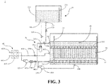
- an embodiment of the present specification provides a cooling apparatus 1 adopting a single-phase immersion liquid cooling technology for cooling a to-be-cooled device 90.
- the to-be-cooled device 90 may be a server in a data center, or may be another heat-producing apparatus that needs to be cooled.
- the cooling apparatus 1 includes a cabinet body 10, a first volumeter 110, and a replenishing device 20.
- the cabinet body 10 may be provided with plug-in components 100, and the to-be-cooled devices 90 which may adopt a sheet-type structure are sequentially plugged in the plug-in components 100.
- the cabinet body 10 here may contain a non-conductive cooling medium 80 for at least partially immersing the to-be-cooled device 90, and the first volumeter 110 is configured to detect the volume of the cooling medium 80 in the cabinet body 10.
- the replenishing device 20 includes a storage tank 210 storing the cooling medium 80, wherein the storage tank 210 and the cabinet body 10 are communicatively connected to each other.
- the first volumeter 110 detects that the volume of the cooling medium 80 in the cabinet body 10 is lower than a first preset volume, the storage tank 210 and the cabinet body 10 come into mutual communication so that the cooling medium 80 in the storage tank 210 is transferred into the cabinet body 10.
- the cooling medium 80 may completely immerse the to-be-cooled device 90 or may partially immerse the to-be-cooled device 90, which may be set according to actual needs.
- the cooling medium 80 may be a gaseous medium, a liquid medium, or a solid-liquid mixed medium, which may also be set according to actual needs.
- the first volumeter 110 may be of a contact type or a non-contact type, which may also be set according to actual needs. Corresponding changes may be made according to different cooling media 80.
- the cooling medium 80 is a liquid
- the first volumeter 110 may be a liquid level gauge.
- the cooling medium 80 completely immerses the to-be-cooled device 90, and the cooling medium 80 is a liquid 3M electronic fluorinated liquid.
- the first volumeter 110 is disposed inside the cabinet body.
- the cooling apparatus 1 of the present specification As the cooling medium 80 in the cabinet body 10 is gradually consumed during use, when the first volumeter 110 detects that the volume of the cooling medium is lower than the first preset volume (i.e., when the volume of the cooling medium in the cabinet body 10 reaches the minimum requirement), the storage tank 210 and the cabinet body 10 come into mutual communication so that the cooling medium 80 in the storage tank 210 of the replenishing device 20 is transferred into the cabinet body 10, thereby realizing the function of automatically replenishing the cooling medium to the cabinet body 10 without manual replenishment, which improves the maintenance efficiency of the cooling apparatus 1 and further improves the cooling efficiency of the cooling apparatus 1 for servers in data centers.
- the cooling apparatus 1 of the present specification further includes a first valve 510 and a control system, the first valve 510 is configured for switching between mutual communication and mutual closure of the storage tank 210 and the cabinet body 10, and the control system is in communication connection with both the first volumeter 110 and the first valve 510.
- the first volumeter 110 sends a detection signal to the control system, and the control system controls the first valve 510 to open so that the storage tank 210 and the cabinet body 10 come into mutual communication.
- the first volumeter 110 When detecting that the volume of the cooling medium 80 in the cabinet body 10 reaches the first preset volume, the first volumeter 110 sends a detection signal to the control system, and the control system controls the first valve 510 to close so that the storage tank 210 and the cabinet body 10 are closed with respect to each other.
- the control system controls the first valve 510 to open or close, thereby achieving the purpose of automatically replenishing the cabinet body 10 or stopping replenishing the cabinet body 10.
- the first valve 510 is a solenoid valve.
- the cooling apparatus 1 of the present application further includes a second volumeter 220 and an alarm device which are in communication connection, wherein the second volumeter 220 is configured to detect the volume of the cooling medium 80 in the storage tank 210.
- the alarm device alarms, further achieving the purpose of notifying an operator to replenish the storage tank 210.
- the control system is in communication connection with both the second volumeter 220 and the alarm device.
- the second volumeter 220 When detecting that the volume of the cooling medium 80 in the storage tank 210 is lower than a second preset volume, the second volumeter 220 sends a detection signal to the control signal and the control system controls the alarm device to alarm. The control system controls the alarm device to give an alarm, thereby achieving the purpose of notifying an operator to replenish the storage tank 210.
- the second volumeter 220 is disposed in the storage tank 210.
- the second volumeter 220 may be of a contact type or a non-contact type, which may also be set according to actual needs. Corresponding changes may be made according to different cooling media 80. For example, if the cooling medium 80 is a liquid, the second volumeter 220 may be a liquid level gauge.
- the cooling apparatus 1 of the present specification further includes a driving device for driving a cooling medium 80 to be transferred between the storage tank 210 and the cabinet body 10; that is, the driving device not only can drive the cooling medium 80 in the storage tank 210 to be transferred into the cabinet body 10, and but also can drive the cooling medium 80 in the cabinet body 10 to be transferred into the storage tank 210.
- the driving device may be a pump, and the control system may control the pump to operate or stop. When the cabinet body 10 needs to be replenished, the cooling medium 80 in the storage tank 210 can be transferred into the cabinet body 10 under the driving of the pump.
- the cooling medium 80 poured into the cabinet body 10 exceeds the upper limit or when it is necessary to empty the cooling medium 80 in the cabinet body 10 (such as for the purpose of relocation), the cooling medium 80 in the cabinet body 10 can be transferred into the storage tank 210 under the driving of the pump.
- the driving device is disposed in the storage tank 210.
- the first volumeter 110 When detecting that the volume of the cooling medium 80 in the cabinet body 10 is lower than the first preset volume, the first volumeter 110 sends a detection signal to the control system, and the control system controls the first valve 510 to open so that the storage tank 210 and the cabinet body 10 come into mutual communication, and the driving device is activated so that the driving device drives the cooling medium 80 in the storage tank 210 to be transferred into the cabinet body 10, and then the cabinet body 10 is automatically replenished.
- the first volumeter 110 When detecting that the volume of the cooling medium 80 in the cabinet body 10 reaches a third preset volume, the first volumeter 110 sends a detection signal to the control system, and the control system controls the first valve 510 to close so that the storage tank 210 and the cabinet body 10 are closed with respect to each other, and the driving device is stopped so that the driving device stops driving the cooling medium 80 in the storage tank 210 to be transferred into the cabinet body 10, thus stopping replenishing the cabinet body 10.
- the third preset volume here is higher than the first preset volume, which means that the first preset volume indicates the lower limit of the allowable volume range of the cooling medium 80 in the cabinet body 10 and the third preset volume indicates the upper limit of the allowable volume range of the cooling medium 80 in the cabinet body10.
- the first volumeter 110 When detecting that the volume of the cooling medium 80 in the cabinet body 10 is higher than the third preset volume, the first volumeter 110 sends a detection signal to the control system, and the control system controls the first valve 510 to open so that the storage tank 210 and the cabinet body 10 come into mutual communication, and the driving device is activated so that the driving device drives the cooling medium 80 in the cabinet body10 to be transferred into the storage tank 210, and the excessive cooling medium 80 in the cabinet body 10 is pumped into the storage tank 210 to avoid the risk of overflow of the excessive cooling medium 80 in the cabinet body 10.
- the first volumeter 110 When detecting that the volume of the cooling medium 80 in the cabinet body 10 is restored to the third preset volume, the first volumeter 110 sends a detection signal to the control system, and the control system controls the first valve 510 to close so that the storage tank 210 and the cabinet body 10 are closed with respect to each other, and the driving device is stopped so that the driving device stops driving the cooling medium 80 in the cabinet body 10 to be transferred into the storage tank 210, thus stopping pumping the cooling medium 80 from the cabinet body 10.
- the first valve 510 can be controlled directly by the control system to open so that the storage tank 210 and the cabinet body 10 come into mutual communication, and the driving device is activated so that the driving device drives the cooling medium 80 in the cabinet body10 to be transferred into the storage tank 210 until the cooling medium 80 in the cabinet body 10 is completely pumped out; the first valve 510 is then closed by the control system so that the storage tank 210 and the cabinet body 10 are closed with respect to each other, and the driving device is stopped from pumping the cooling medium 80 out of the cabinet body 10.
- the cabinet body 10 is provided with a first diversion opening 101 for guiding the cooling medium 80
- the storage tank 210 is provided with a second diversion opening 211 in communication with the first diversion opening 101
- the first valve 510 is disposed between the first diversion opening 101 and the second diversion opening 211 or disposed inside the storage tank 210 at a position corresponding to the second diversion opening 211, and the first diversion opening 101 and the second diversion opening 211 may be connected through a pipeline.
- the storage tank 210 is disposed above the cabinet body 10, and the second diversion opening 211 is located above the first diversion opening 101 so that the liquid level of the cooling medium 80 in the storage tank 210 is higher than the liquid level of the cooling medium 80 in the cabinet body 10.
- the first valve 510 is opened so that the cooling medium 80 in the storage tank 210 can directly flow into the cabinet body 10 under the action of gravity.
- the cooling apparatus 1 of the present application further includes a heat exchanging device 40, wherein one end of the heat exchanging device 40 is provided in communication with the cabinet body 10, and the other end of the heat exchanging device 40 is provided in communication with an external liquid supply apparatus; and the heat exchanging device 40 is configured to drive the cooling medium 80 to circulate in the cabinet body 10 and to exchange heat with the cooling medium 80.
- the heat exchanging device 40 drives the cooling medium 80 to circulate in the cabinet body 10 of the cooling apparatus 1 to take away heat of the to-be-cooled device 90, and the heat exchanging device 40 exchanges heat with the external liquid supply apparatus so that the cooling medium 80 reaches a low temperature state again, and circulates into the cabinet body 10 of the cooling apparatus 1 to cool the to-be-cooled device 90 again, thus achieving the purpose of circularly and continuously discharging the heat of the to-be-cooled device 90.
- the cabinet body 10 is further provided with a diversion inlet 102 for introducing the cooling medium 80 and a diversion outlet 103 for discharging the cooling medium 80.
- the heat exchanging device 40 includes a heat exchanger 410 and a diversion pump 420.
- the heat exchanger 410 is connected to the cooling body 10 of the cooling apparatus 1 through a first circulation loop, and is connected to the external liquid supply apparatus through a second circulation loop.
- the first circulation loop includes a first pipeline 430 and a second pipeline 440
- the second circulation loop includes a third pipeline 450 and a fourth pipeline 460.
- the first pipeline 430 is provided in communication with the diversion inlet 102 on the cabinet body 10 of the cooling apparatus 1
- the second pipeline 440 is provided in communication with the diversion outlet 103 on the cabinet body 10 of the cooling apparatus 1
- the third pipeline 450 and the fourth pipeline 460 are both provided in communication with the external liquid supply apparatus.
- the heat exchanging device 40 may further include a flow meter 470, and the flow meter 470 may be disposed between the diversion pump 420 and the cabinet body 10 and used for detecting the flow rate of the cooling medium 80.
- the pressure of the diversion pump 420 may be adjusted according to the detection result of the flow meter 470, so as to achieve the purpose of adjusting the flow rate of the cooling medium 80.
- Each of the first pipeline 430 and the second pipeline 440 may be provided with a valve 480 to open or close a pipeline passage through which the cooling medium 80 circulates in the heat exchanging device 40.
- the pump drives the cooling medium 80 to circulate in the cabinet body 10 of the cooling apparatus 1 through the first circulation loop, and the cooling medium 80 takes away the heat of the to-be-cooled device 90 through the circulation in the cabinet body 10 of the cooling apparatus 1 and enters the heat exchanger 410 of the heat exchanging device 40.
- the external liquid supply apparatus can circularly provide cooling water in the second circulation loop, and the cooling medium 80 carrying the heat of the to-be-cooled device 90 may exchange heat in the heat exchanger 410 with the cooling water provided by the external liquid supply apparatus to discharge the heat carried by the cooling medium 80 so that the cooling medium 80 reaches a low temperature state again, which can cool the to-be-cooled device 90 again after circulating into the cooling apparatus 1, thus achieving the purpose of circularly and continuously discharging the heat of the to-be-cooled device 90.
- an embodiment of the present specification provides a cooling apparatus 1 adopting a single-phase immersion liquid cooling technology for cooling a to-be-cooled device 90.
- the to-be-cooled device 90 may be a server in a data center or may be another heat-producing apparatus that needs to be cooled.
- the cooling apparatus 1 includes a cabinet body 10 and a filtering device 30.
- the cabinet body 10 may be provided with plug-in components 100, and the to-be-cooled devices 90 which may adopt a sheet-type structure are sequentially plugged in the plug-in components 100.
- the cabinet body 10 may contain a cooling medium 80 for at least partially immersing the to-be-cooled device 90, and the cabinet body 10 is provided with a first diversion opening 101 for introducing the cooling medium 80 and a third diversion opening 104 for discharging the cooling medium 80.
- the filtering device 30 is provided with a fourth diversion opening 301 in communication with the first diversion opening 101 of the cabinet body 10 and a fifth diversion opening 302 in communication with the third diversion opening 104, and the filtering device 30 is configured to drive the cooling medium 80 in the cabinet body 10 to flow through the filtering device 30 for filtering.
- the cooling medium 80 may completely immerse the to-be-cooled device 90, or may partially immerse the to-be-cooled device 90, which may be set according to actual needs.
- the cooling medium 80 may be a gaseous medium, a liquid medium, or a solid-liquid mixed medium, which may also be set according to actual needs.
- the cooling medium 80 completely immerses the to-be-cooled device 90, and the cooling medium 80 is a liquid 3M electronic fluorinated liquid.
- the third diversion opening104 may be disposed at the bottom of the cabinet body 10, the first diversion opening 101 and the fourth diversion opening 301 may be connected by a pipeline, and the third diversion opening 104 and the fifth diversion opening 302 may be connected by a pipeline.
- the cooling medium 80 in the cabinet body 10 is gradually polluted during use, the cooling medium 80 can be filtered by the filtering device 30 to filter out impurities in the cooling medium 80 to ensure that the cooling apparatus 1 can operate properly with no need of manual replacement of the cooling medium 80 on a regular basis, which improves the maintenance efficiency of the cooling apparatus 1 and further improves the cooling efficiency of the cooling apparatus 1 for the servers in data centers.
- the filtering device 30 includes a filter 310 and a driving pump 320 provided in communication with the filter 310.
- the driving pump 320 is configured to drive the cooling medium 80 in the cabinet body 10 to flow through the filter 310 for filtering.
- One of the filter 310 and the driving pump 320 is provided with the fourth diversion opening 301, and the other of the filter 310 and the driving pump 320 is provided with the fifth diversion opening 302.
- the driving pump 320 is located closer to the third diversion opening 104 of the cabinet body 10, and the filter 310 is located closer to the first diversion opening 101 of the cabinet body 10; therefore, the fourth diversion opening 301 is disposed in the filter 310, and the fifth diversion opening 302 is disposed in the driving pump 320.
- the cooling medium 80 in the cabinet body 10 can be driven by the driving pump 320 to flow through the filter 310 for filtering so that impurities in the cooling medium 80 are filtered out, thus ensuring the normal operation of the cooling apparatus 1.
- the cooling apparatus 1 of the present specification further includes a control system, a first detection system, and a second valve 520.
- the second valve 520 is preferably a solenoid valve, and the control system is in communication connection with the driving pump 320, the first detection system and the second valve 520.
- the first detection system is configured to detect the purity of the cooling medium 80 in the cabinet body 10, and the second valve 520 is disposed between the first diversion opening 101 and the fourth diversion opening 301 or between the third diversion opening 104 and the fifth diversion opening 302. In the example shown in the figure, the second valve 520 is disposed between the first diversion opening 101 and the fourth diversion opening 301.
- the first detection system When the first detection system detects that the purity of the cooling medium 80 in the cabinet body 10 is lower than a set value, it indicates that the purity of the cooling medium 80 in the cabinet body 10 does not meet the requirements, the first detection system then sends a detection signal to the control system, and the control system controls the second valve 520 to open and activates the driving pump 320 so that the driving pump 320 drives the cooling medium 80 in the cabinet body 10 to flow through the filter 310 for filtering, and thus the cooling medium 80 in the cabinet body 10 is filtered automatically.
- the first detection system detects that the purity of the cooling medium 80 in the cabinet body 10 reaches a set value, it indicates that the purity of the cooling medium 80 in the cabinet body 10 meets the requirements, the first detection system then sends a detection signal to the control system, and the control system controls the second valve 520 to close and stops the driving pump 320 so that the driving pump 320 stops driving the cooling medium 80 in the cabinet body 10 to flow through the filter 310 for filtering.
- the control system may also always control the second valve 520 to open and control the driving pump 320 to always be in an operating state so that the driving pump 320 circularly drives the cooling medium 80 in the cabinet body 10 to flow through the filter 310 for filtering, thus ensuring that the cooling medium 80 in the cabinet body 10 is always kept clean.
- the cooling apparatus 1 of the present application further includes a storage device 70 provided in communication with the driving pump 320, and the driving pump 320 is further configured to drive the cooling medium 80 in the cabinet body 10 to be transferred into the storage device 70.
- the cooling medium 80 in the cabinet body 10 is transferred into the storage device 70 under the driving of the driving pump 320.
- the cooling apparatus 1 of the present specification further includes a third valve 530 disposed between the storage device 70 and the driving pump 320.
- the third valve 530 is preferably a solenoid valve.
- the third valve 530 can be controlled by the control system to open and the driving pump 320 is activated so that the driving pump 320 drives the cooling medium 80 in the cabinet body 10 to be transferred into the storage device 70 until the cooling medium 80 in the cabinet body 10 is completely pumped out; the third valve 530 is then closed by the control system, and the driving pump 320 is further stopped.
- the cooling apparatus 1 of the present specification further includes a cover disposed at the top of the cabinet body 10, a control system in communication connection with the filtering device 30, and a second detection system in communication connection with the control system, and the second detection system is configured to detect the state (open/closed) of the cover.
- the second detection system detects that the cover is in a closed state, it sends a first detection signal to the control system, and the control system controls the filtering device 30 to stop.
- the second detection system detects that the cover is in an open state, it sends a second detection signal to the control system, and the control system controls the filtering device 30 to operate. That is to say, whether the cover of the cabinet body 10 is open is considered as the trigger condition of the filtering device 30.
- the filtering device 30 operates. The filtering device 30 starts filtering the cooling medium only when the cover of the cabinet body10 is open, which can reduce energy consumption.
- the cooling apparatus 1 of the present application further includes a heat exchanging device 40, wherein one end of the heat exchanging device 40 is provided in communication with the cabinet body 10, and the other end of the heat exchanging device 40 is provided in communication with an external liquid supply apparatus; the heat exchanging device 40 is configured to drive the cooling medium 80 to circulate in the cabinet body 10 and to exchange heat with the cooling medium 80.
- the heat exchanging device 40 drives the cooling medium 80 to circulate in the cabinet body 10 of the cooling apparatus 1 to take away heat of the to-be-cooled device 90, and the heat exchanging device 40 exchanges heat with the external liquid supply apparatus so that the cooling medium 80 reaches a low temperature state again, and circulates into the cabinet body 10 of the cooling apparatus 1 to cool the to-be-cooled device 90 again, thus achieving the purpose of circularly and continuously discharging the heat of the to-be-cooled device 90.
- the cabinet body 10 is further provided with a diversion inlet 102 for introducing the cooling medium 80 and a diversion outlet 103 for discharging the cooling medium 80.
- the heat exchanging device 40 includes a heat exchanger 410 and a diversion pump 420.
- the heat exchanger 410 is connected to the cooling body 10 of the cooling apparatus 1 through a first circulation loop, and is connected to the external liquid supply apparatus through a second circulation loop.
- the first circulation loop includes a first pipeline 430 and a second pipeline 440
- the second circulation loop includes a third pipeline 450 and a fourth pipeline 460.
- the first pipeline 430 is provided in communication with the diversion inlet 102 on the cabinet body 10 of the cooling apparatus 1
- the second pipeline 440 is provided in communication with the diversion outlet 103 on the cabinet body 10 of the cooling apparatus 1
- the third pipeline 450 and the fourth pipeline 460 are both provided in communication with the external liquid supply apparatus.
- the heat exchanging device 40 may further include a flow meter 470, and the flow meter 470 may be disposed between the diversion pump 420 and the cabinet body 10 and used for detecting the flow rate of the cooling medium 80.
- the pressure of the diversion pump 420 may be adjusted according to the detection result of the flow meter 470, so as to achieve the purpose of adjusting the flow rate of the cooling medium 80.
- Each of the first pipeline 430 and the second pipeline 440 may be provided with a valve 480 to open or close a pipeline passage through which the cooling medium 80 circulates in the heat exchanging device 40.
- the pump drives the cooling medium 80 to circulate in the cabinet body 10 of the cooling apparatus 1 through the first circulation loop, and the cooling medium 80 takes away the heat of the to-be-cooled device 90 through the circulation in the cabinet body 10 of the cooling apparatus 1 and enters the heat exchanger 410 of the heat exchanging device 40.
- the external liquid supply apparatus can circularly provide cooling water in the second circulation loop, and the cooling medium 80 carrying the heat of the to-be-cooled device 90 may exchange heat in the heat exchanger 410 with the cooling water provided by the external liquid supply apparatus to discharge the heat carried by the cooling medium 80 so that the cooling medium 80 reaches a low temperature state again, which can cool the to-be-cooled device 90 again after circulating into the cooling apparatus 1, thus achieving the purpose of circularly and continuously discharging the heat of the to-be-cooled device 90.
- an embodiment of the present specification provides a cooling apparatus 1 adopting a single-phase immersion liquid cooling technology for cooling a to-be-cooled device 90.
- the to-be-cooled device 90 may be a server in a data center, or may be another heat-producing apparatus that needs to be cooled.
- the cooling apparatus 1 includes a cabinet body 10, a first volumeter 110, a replenishing device 20 and a filtering device 30.
- the cabinet body 10 may be provided with plug-in components 100, and the to-be-cooled devices 90 which may adopt a sheet-type structure are sequentially plugged in the plug-in components 100.
- the cabinet body 10 may contain a cooling medium 80 for at least partially immersing the to-be-cooled device 90; the cabinet body 10 is provided with a first diversion opening 101 for introducing the cooling medium 80 and a third diversion opening 104 for discharging the cooling medium 80; and the first volumeter 110 is configured to detect the volume of the cooling medium 80 in the cabinet body 10.
- the replenishing device 20 includes a storage tank 210 storing the cooling medium 80, wherein the storage tank 210 and the cabinet body 10 are communicatively connected to each other.
- the filtering device 30 is provided with a fourth diversion opening 301 in communication with the first diversion opening 101 of the cabinet body 10 and a fifth diversion opening 302 in communication with the third diversion opening 104, and the filtering device 30 is configured to drive the cooling medium 80 in the cabinet body 10 to flow through the filtering device 30 for filtering.
- the first volumeter 110 detects that the volume of the cooling medium 80 in the cabinet body 10 is higher than a third preset volume
- the storage tank 210 and the cabinet body 10 come into mutual communication, and the filtering device 30 drives the cooling medium 80 in the cabinet body 10 to be transferred into the storage tank 210.
- the cooling medium 80 may completely immerse the to-be-cooled device 90, or may partially immerse the to-be-cooled device 90, which may be set according to actual needs.
- the cooling medium 80 may be a gaseous medium, a liquid medium, or a solid-liquid mixed medium, which may also be set according to actual needs.
- the first volumeter 110 may be of a contact type or a non-contact type, which may also be set according to actual needs. Corresponding changes may be made according to different cooling media 80. For example, if the cooling medium 80 is a liquid, the first volumeter 110 may be a liquid level gauge.
- the cooling medium 80 completely immerses the to-be-cooled device 90, and the cooling medium 80 is a liquid 3M electronic fluorinated liquid.
- the first volumeter 110 is disposed inside the cabinet body.
- the third diversion opening104 may be disposed at the bottom of the cabinet body 10, the first diversion opening 101 and the fourth diversion opening 301 may be connected by a pipeline, and the third diversion opening 104 and the fifth diversion opening 302 may be connected by a pipeline.
- the cooling apparatus 1 of the present specification organically combines both the replenishing device 20 and the filtering device 30.
- the cooling medium 80 in the cabinet body 10 exceeds the third preset volume (i.e., when the volume is overloaded)
- the storage tank 210 and the cabinet body 10 come into mutual communication, and the filtering device 30 drives the cooling medium 80 in the cabinet body 10 to be transferred into the storage tank 210, thus avoiding the risk of overflow of the excessive cooling medium 80 in the cabinet body 10.
- the cooling apparatus 1 of the present application further includes a second volumeter 220 and an alarm device which are in communication connection, wherein the second volumeter 220 is configured to detect the volume of the cooling medium 80 in the storage tank 210.
- the alarm device alarms, further achieving the purpose of notifying an operator to replenish the storage tank 210.
- the control system is in communication connection with both the second volumeter 220 and the alarm device.
- the second volumeter 220 When detecting that the volume of the cooling medium 80 in the storage tank 210 is lower than a second preset volume, the second volumeter 220 sends a detection signal to the control signal and the control system controls the alarm device to alarm. The control system controls the alarm device to give an alarm, thereby achieving the purpose of notifying an operator to replenish the storage tank 210.
- the second volumeter 220 is disposed in the storage tank 210.
- the second volumeter 220 may be of a contact type or a non-contact type, which may also be set according to actual needs. Corresponding changes may be made according to different cooling media 80. For example, if the cooling medium 80 is a liquid, the second volumeter 220 may be a liquid level gauge.
- the filtering device 30 includes a filter 310 and a driving pump 320 provided in communication with the filter 310.
- the driving pump 320 is configured to drive the cooling medium 80 in the cabinet body 10 to flow through the filter 310 for filtering.
- One of the filter 310 and the driving pump 320 is provided with the fourth diversion opening 301, and the other of the filter 310 and the driving pump 320 is provided with the fifth diversion opening 302.
- the driving pump 320 is located closer to the third diversion opening 104 of the cabinet body 10, and the filter 310 is located closer to the first diversion opening 101 of the cabinet body 10; therefore, the fourth diversion opening 301 is disposed in the filter 310, and the fifth diversion opening 302 is disposed in the driving pump 320.
- the cooling medium 80 in the cabinet body 10 can be driven by the driving pump 320 to flow through the filter 310 for filtering so that impurities in the cooling medium 80 are filtered out, thus ensuring the normal operation of the cooling apparatus 1.
- the cooling medium 80 in the cabinet body 10 can be filtered by the filtering device 30 to filter out impurities in the cooling medium 80 to ensure the normal operation of the cooling apparatus 1 with no need of manual replacement of the cooling medium 80 on a regular basis, which improves the maintenance efficiency of the cooling apparatus 1 and further improves the cooling efficiency of the cooling apparatus 1 for the servers in data centers.
- the cooling apparatus 1 of the present specification further includes a control system, a first detection system, and a second valve 520.
- the second valve 520 is preferably a solenoid valve, and the control system is in communication connection with the driving pump 320 of the filtering device 30, the first detection system and the second valve 520.
- the first detection system is configured to detect the purity of the cooling medium 80 in the cabinet body 10, and the second valve 520 is disposed between the first diversion opening 101 and the fourth diversion opening 301 or between the third diversion opening 104 and the fifth diversion opening 302. In the example shown in the figure, the second valve 520 is disposed between the first diversion opening 101 and the fourth diversion opening 301.
- the first detection system When the first detection system detects that the purity of the cooling medium 80 in the cabinet body 10 is lower than a set value, it indicates that the purity of the cooling medium 80 in the cabinet body 10 does not meet the requirements, the first detection system then sends a detection signal to the control system, and the control system controls the second valve 520 to open and activates the driving pump 320 of the filtering device 30 so that the driving pump 320 drives the cooling medium 80 in the cabinet body 10 to flow through the filter 310 for filtering, and thus the cooling medium 80 in the cabinet body 10 is filtered automatically.
- the first detection system detects that the purity of the cooling medium 80 in the cabinet body 10 reaches a set value, it indicates that the purity of the cooling medium 80 in the cabinet body 10 meets the requirements, the first detection system then sends a detection signal to the control system, and the control system controls the second valve 520 to close and stops the driving pump 320 of the filtering device 30 so that the driving pump 320 stops driving the cooling medium 80 in the cabinet body 10 to flow through the filter 310 for filtering.
- control system may also always control the second valve 520 to open and control the driving pump 320 to always be in an operating state so that the driving pump 320 circularly drives the cooling medium 80 in the cabinet body 10 to flow through the filter 310 for filtering, thus ensuring that the cooling medium 80 in the cabinet body 10 is always kept clean.
- the cooling apparatus 1 of the present specification further includes a cover disposed at the top of the cabinet body 10 and a second detection system in communication connection with the control system, and the second detection system is configured to detect the state (open/closed) of the cover.
- the second detection system detects that the cover is in a closed state, it sends a first detection signal to the control system, and the control system controls the filtering device 30 to stop.
- the second detection system detects that the cover is in an open state, it sends a second detection signal to the control system, and the control system controls the filtering device 30 to operate. That is to say, whether the cover of the cabinet body 10 is open is considered as the trigger condition of the filtering device 30.
- the filtering device 30 operates. The filtering device 30 starts filtering the cooling medium only when the cover of the cabinet body10 is open, which can reduce energy consumption.
- the storage tank 210 of the replenishing device 20 is provided in communication with the driving pump 320 of the filtering device 30.
- the driving pump 320 of the filtering device 30 is further configured to drive a cooling medium 80 to be transferred between the storage tank 210 and the cabinet body 10; that is, the driving pump 320 of the filtering device 30 not only can drive the cooling medium 80 in the storage tank 210 to be transferred into the cabinet body 10, and but also can drive the cooling medium 80 in the cabinet body 10 to be transferred into the storage tank 210.
- the cooling medium 80 in the storage tank 210 can be transferred into the cabinet body 10 under the driving of the driving pump 320.
- the cooling medium 80 poured into the cabinet body 10 exceeds the upper limit or when it is necessary to empty the cooling medium 80 in the cabinet body 10 (such as for the purpose of relocation), the cooling medium 80 in the cabinet body 10 can be transferred into the storage tank 210 under the driving of the driving pump 320.
- the cooling apparatus 1 of the present specification further includes a third valve 530 disposed between the storage tank 210 and the driving pump 320.
- the third valve 530 is preferably a solenoid valve.
- the first volumeter 110 sends a detection signal to the control system, and the control system controls the third valve 530 to open and activates the driving pump 320 of the filtering device 30 so that the driving pump 320 drives the cooling medium 80 in the cabinet body 10 to be transferred into the storage tank 210, and the excessive cooling medium 80 in the cabinet body 10 is pumped into the storage tank 210, thus avoiding the risk of overflow of the excessive cooling medium 80 in the cabinet body 10.
- the first volumeter 110 When detecting that the volume of the cooling medium 80 in the cabinet body 10 is restored to the third preset volume, the first volumeter 110 sends a detection signal to the control system, and the control system controls the third valve 530 to close and stops the driving pump 320 of the filtering device 30 so that the driving pump 320 stops driving the cooling medium 80 in the cabinet body 10 to be transferred into the storage tank 210, thus stopping pumping the cooling medium 80 from the cabinet body 10.
- the third valve 530 can be directly controlled by the control system to open and the driving pump 320 of the filtering device 30 is activated so that the driving pump 320 drives the cooling medium 80 in the cabinet body 10 to be transferred into the storage tank 210 until the cooling medium 80 in the cabinet body 10 is completely pumped out; the third valve 530 is then closed by the control system, and the driving pump 320 is further stopped.
- the driving pump 320 of the filtering device 30 is used to perform the integrated drainage operation on the cooling medium 80 in the cabinet body 10, and no additional apparatus is required to pump the cooling medium 80 out of the cabinet body 10.
- the first volumeter 110 When detecting that the volume of the cooling medium 80 in the cabinet body 10 is lower than the first preset volume, the first volumeter 110 sends a detection signal to the control system, and the control system controls the first valve 510 to open so that the storage tank 210 and the cabinet body 10 come into mutual communication, and the driving pump 320 of the filtering device 30 is activated so that the driving pump 320 drives the cooling medium 80 in the storage tank 210 to be transferred into the cabinet body 10, and then the cabinet body 10 is automatically replenished.
- the first volumeter 110 When detecting that the volume of the cooling medium 80 in the cabinet body 10 reaches the third preset volume, the first volumeter 110 sends a detection signal to the control system, and the control system controls the first valve 510 to close so that the storage tank 210 and the cabinet body 10 are closed with respect to each other, and the driving pump 320 of the filtering device 30 is stopped so that the driving pump 320 stops driving the cooling medium 80 in the storage tank 210 to be transferred into the cabinet body 10, thus stopping replenishing the cabinet body 10.
- the third preset volume here is higher than the third preset volume, which means that the first preset volume indicates the lower limit of the allowable volume range of the cooling medium 80 in the cabinet body 10 and the third preset volume indicates the upper limit of the allowable volume range of the cooling medium 80 in the cabinet body10.
- the cooling apparatus 1 of the present specification further includes a first valve 510, the first valve 510 is configured for switching between mutual communication and mutual closure of the storage tank 210 and the cabinet body 10, and the control system is in communication connection with the driving pump 320 of the filtering device 30, the first volumeter 110, and the first valve 510.
- the first volumeter 110 When detecting that the volume of the cooling medium 80 in the cabinet body 10 is lower than the first preset volume, the first volumeter 110 sends a detection signal to the control system, and the control system controls the first valve 510 to open so that the storage tank 210 and the cabinet body 10 come into mutual communication, and the driving device is activated so that the driving pump 320 of the filtering device 30 drives the cooling medium 80 in the storage tank 210 to be transferred into the cabinet body 10, and then the cabinet body 10 is automatically replenished.
- the first volumeter 110 When detecting that the volume of the cooling medium 80 in the cabinet body 10 reaches the first preset volume, the first volumeter 110 sends a detection signal to the control system, and the control system controls the first valve 510 to close so that the storage tank 210 and the cabinet body 10 are closed with respect to each other, and the driving pump 320 of the filtering device 30 stops driving the cooling medium 80 in the storage tank 210 to be transferred into the cabinet body 10, thus stopping replenishing the cabinet body 10.
- the control system controls the first valve 510 and the driving pump 320 of the filtering device 30 to open or close, thereby achieving the purpose of automatically replenishing the cabinet body 10 or stopping replenishing the cabinet body 10 with no need of manual replenishment; therefore, the maintenance efficiency of the cooling apparatus 1 is improved, and the cooling efficiency of the cooling apparatus 1 for the servers in data centers is further improved.
- the first valve 510 is a solenoid valve.
- the storage tank 210 is provided with a second diversion opening 211 in communication with the first diversion opening 101 of the cabinet body 10, the first valve 510 is disposed between the first diversion opening 101 and the second diversion opening 211 or disposed inside the storage tank 210 at a position corresponding to the second diversion opening 211, and the first diversion opening 101 and the second diversion opening 211 may be connected through a pipeline. Further, the storage tank 210 is disposed above the cabinet body 10, and the second diversion opening 211 is located above the first diversion opening 101 so that the liquid level of the cooling medium 80 in the storage tank 210 is higher than the liquid level of the cooling medium 80 in the cabinet body 10. When the cabinet body 10 needs to be replenished, the first valve 510 is opened so that the cooling medium 80 in the storage tank 210 can directly flow into the cabinet body 10 under the action of gravity.
- the cooling apparatus 1 of the present application further includes a heat exchanging device 40, wherein one end of the heat exchanging device 40 is provided in communication with the cabinet body 10, and the other end of the heat exchanging device 40 is provided in communication with an external liquid supply apparatus; the heat exchanging device 40 is configured to drive the cooling medium 80 to circulate in the cabinet body 10 and to exchange heat with the cooling medium 80.
- the heat exchanging device 40 drives the cooling medium 80 to circulate in the cabinet body 10 of the cooling apparatus 1 to take away heat of the to-be-cooled device 90, and the heat exchanging device 40 exchanges heat with the external liquid supply apparatus so that the cooling medium 80 reaches a low temperature state again, and circulates into the cabinet body 10 of the cooling apparatus 1 to cool the to-be-cooled device 90 again, thus achieving the purpose of circularly and continuously discharging the heat of the to-be-cooled device 90.
- the cabinet body 10 is further provided with a diversion inlet 102 for introducing the cooling medium 80 and a diversion outlet 103 for discharging the cooling medium 80.
- the heat exchanging device 40 includes a heat exchanger 410 and a diversion pump 420.
- the heat exchanger 410 is connected to the cooling body 10 of the cooling apparatus 1 through a first circulation loop, and is connected to the external liquid supply apparatus through a second circulation loop.
- the first circulation loop includes a first pipeline 430 and a second pipeline 440
- the second circulation loop includes a third pipeline 450 and a fourth pipeline 460.
- the first pipeline 430 is provided in communication with the diversion inlet 102 on the cabinet body 10 of the cooling apparatus 1
- the second pipeline 440 is provided in communication with the diversion outlet 103 on the cabinet body 10 of the cooling apparatus 1
- the third pipeline 450 and the fourth pipeline 460 are both provided in communication with the external liquid supply apparatus.
- the heat exchanging device 40 may further include a flow meter 470, and the flow meter 470 may be disposed between the diversion pump 420 and the cabinet body 10 and used for detecting the flow rate of the cooling medium 80.
- the pressure of the diversion pump 420 may be adjusted according to the detection result of the flow meter 470, so as to achieve the purpose of adjusting the flow rate of the cooling medium 80.
- Each of the first pipeline 430 and the second pipeline 440 may be provided with a valve 480 to open or close a pipeline passage through which the cooling medium 80 circulates in the heat exchanging device 40.
- the pump drives the cooling medium 80 to circulate in the cabinet body 10 of the cooling apparatus 1 through the first circulation loop, and the cooling medium 80 takes away the heat of the to-be-cooled device 90 through the circulation in the cabinet body 10 of the cooling apparatus 1 and enters the heat exchanger 410 of the heat exchanging device 40.
- the external liquid supply apparatus can circularly provide cooling water in the second circulation loop, and the cooling medium 80 carrying the heat of the to-be-cooled device 90 may exchange heat in the heat exchanger 410 with the cooling water provided by the external liquid supply apparatus to discharge the heat carried by the cooling medium 80 so that the cooling medium 80 reaches a low temperature state again, which can cool the to-be-cooled device 90 again after circulating into the cooling apparatus 1, thus achieving the purpose of circularly and continuously discharging the heat of the to-be-cooled device 90.
Landscapes
- Engineering & Computer Science (AREA)
- Microelectronics & Electronic Packaging (AREA)
- Physics & Mathematics (AREA)
- Thermal Sciences (AREA)
- Computer Hardware Design (AREA)
- General Engineering & Computer Science (AREA)
- Cooling Or The Like Of Electrical Apparatus (AREA)
Abstract
Description
- The present application claims priority to Chinese Patent Application No.
201711071271.6 - The present specification relates to the technical field of heat dissipating apparatuses, and in particular, to a cooling apparatus.
- With the rapid development of cloud computing technology (i.e., large-scale distributed system technology), the requirements for computing performance of servers are getting higher and higher. While server performance is improving, power consumption is increasing rapidly, and the power consumption of the cabinet has increased exponentially. Data shows that the power density of data center cabinets has increased by nearly 15 times in the past decade. In the past, the power consumption of a cabinet was generally 1.5kW-2kW. However, the power consumption of some cabinets has locally reached as high as 20kW-30kW.
- Servers in data centers are usually cooled by way of air-conditioning and air-cooling. However, with the steady increase in power density, the cooling capacity provided by many data centers is approaching the limit currently. Therefore, the conventional way of air-conditioning and air-cooling has been unable to meet the cooling demand of the servers in data centers. In addition, air-conditioning and air-cooling ways are consuming a large amount of energy, space and cost, and the consumption is increasing.
- The present specification provides a cooling apparatus to improve the cooling efficiency for the servers in data centers.
- According to a first aspect of the embodiments of the present specification, provided is a cooling apparatus for cooling a to-be-cooled device, and the cooling apparatus includes:
- a cabinet body configured to contain a cooling medium for at least partially immersing the to-be-cooled device;
- a first volumeter for detecting the volume of the cooling medium in the cabinet body; and
- a replenishing device including a storage tank storing a cooling medium, wherein the storage tank and the cabinet body are communicatively connected to each other; and
- when the first volumeter detects that the volume of the cooling medium in the cabinet body is lower than a first preset volume, the storage tank and the cabinet body come into mutual communication so that the cooling medium in the storage tank is transferred into the cabinet body.
- Further, the cooling apparatus further includes a second volumeter and an alarm device which are in communication connection, wherein the second volumeter is configured to detect the volume of the cooling medium in the storage tank; and
when the second volumeter detects that the volume of the cooling medium in the storage tank is lower than a second preset volume, the alarm device alarms. - Further, the cooling apparatus further includes a driving device for driving the cooling medium to be transferred between the storage tank and the cabinet body.
- Further, when the first volumeter detects that the volume of the cooling medium in the cabinet body is lower than the first preset volume, the storage tank and the cabinet body come into mutual communication, and the driving device drives the cooling medium in the storage tank to be transferred into the cabinet body; and
when the first volumeter detects that the volume of the cooling medium in the cabinet body reaches a third preset volume, the storage tank and the cabinet body are closed with respect to each other, and the driving device stops, wherein the third preset volume is higher than the first preset volume. - Further, when the first volumeter detects that the volume of the cooling medium in the cabinet body exceeds a third preset volume, the storage tank and the cabinet body come into mutual communication, and the driving device drives the cooling medium in the cabinet body to be transferred into the storage tank; and
when the first volumeter detects that the volume of the cooling medium in the cabinet body is restored to the third preset volume, the storage tank and the cabinet body are closed with respect to each other, and the driving device stops, wherein the third preset volume is higher than the first preset volume. - Further, the cooling apparatus further includes a first valve and a control system, the first valve is configured for switching between mutual communication and mutual closure of the storage tank and the cabinet body, and the control system is in communication connection with both the first volumeter and the first valve; and
when the first volumeter detects that the volume of the cooling medium in the cabinet body is lower than the first preset volume, the control system controls the first valve to open so that the storage tank and the cabinet body come into mutual communication; when the first volumeter detects that the volume of the cooling medium in the cabinet body reaches the first preset volume, the control system controls the first valve to close so that the storage tank and the cabinet body are closed with respect to each other. - Further, the cabinet body is provided with a first diversion opening for guiding the cooling medium, the storage tank is provided with a second diversion opening in communication with the first diversion opening, and the first valve is disposed between the first diversion opening and the second diversion opening or disposed inside the storage tank at a position corresponding to the second diversion opening.
- Further, the storage tank is disposed above the cabinet body, and the second diversion opening is located above the first diversion opening.
- Further, the cooling apparatus further includes a heat exchanging device, wherein one end of the heat exchanging device is provided in communication with the cabinet body, and the other end of the heat exchanging device is provided in communication with an external liquid supply apparatus; the heat exchanging device is configured to drive the cooling medium to circulate in the cabinet body and to exchange heat with the cooling medium.
- According to a second aspect of the embodiments of the present specification, provided is a cooling apparatus for cooling a to-be-cooled device, and the cooling apparatus includes:
- a cabinet body configured to contain a cooling medium for at least partially immersing the to-be-cooled device, wherein the cabinet body is provided with a first diversion opening for introducing the cooling medium and a third diversion opening for discharging the cooling medium; and
- a filtering device, wherein the filtering device is provided with a fourth diversion opening in communication with the first diversion opening and a fifth diversion opening in communication with the third diversion opening, and the filtering device is configured to drive the cooling medium in the cabinet body to flow through the filtering device for filtering.
- Further, the filtering device includes a filter and a driving pump provided in communication with the filter, the driving pump is configured to drive the cooling medium in the cabinet body to flow through the filter for filtering; one of the filter and the driving pump is provided with the fourth diversion opening, and the other of the filter and the driving pump is provided with the fifth diversion opening.
- Further, the cooling apparatus further includes a first detection system and a second valve, wherein the first detection system is configured to detect the purity of the cooling medium in the cabinet body, and the second valve is disposed between the first diversion opening and the fourth diversion opening or between the third diversion opening and the fifth diversion opening; and
when the first detection system detects that the purity of the cooling medium in the cabinet body is lower than a set value, the second valve is opened, and the driving pump drives the cooling medium in the cabinet body to flow through the filter for filtering. - Further, the cooling apparatus further includes a storage device provided in communication with the driving pump, and the driving pump is further configured to drive the cooling medium in the cabinet body to be transferred into the storage device.
- Further, the cooling apparatus further includes a third valve provided between the storage device and the driving pump; when the third valve is opened, the driving pump drives the cooling medium in the cabinet body to be transferred into the storage device.
- Further, the cooling apparatus further includes a cover disposed at the top of the cabinet body, a control system in communication connection with the filtering device, and a second detection system in communication connection with the control system, the second detection system is configured to detect whether the cover is open or closed; when detecting that the cover is in a closed state, the second detection system sends a first detection signal to the control system, and the control system controls the filtering device to stop; when detecting that the cover is in an open state, the second detection system sends a second detection signal to the control system, and the control system controls the filtering device to operate.
- Further, the cooling apparatus further includes a heat exchanging device, wherein one end of the heat exchanging device is provided in communication with the cabinet body, and the other end of the heat exchanging device is provided in communication with an external liquid supply apparatus; the heat exchanging device is configured to drive the cooling medium to circulate in the cabinet body and to exchange heat with the cooling medium.
- According to a third aspect of the embodiments of the present specification, provided is a cooling apparatus for cooling a to-be-cooled device, and the cooling apparatus includes:
- a cabinet body configured to contain a cooling medium for at least partially immersing the to-be-cooled device, wherein the cabinet body is provided with a first diversion opening for introducing the cooling medium and a third diversion opening for discharging the cooling medium;
- a first volumeter for detecting the volume of the cooling medium in the cabinet body;
- a replenishing device including a storage tank storing a cooling medium, wherein the storage tank and the cabinet body are communicatively connected to each other; and
- a filtering device, wherein the filtering device is provided with a fourth diversion opening in communication with the first diversion opening and a fifth diversion opening in communication with the third diversion opening, and the filtering device is configured to drive the cooling medium in the cabinet body to flow through the filtering device for filtering;
- when the first volumeter detects that the volume of the cooling medium in the cabinet body exceeds a third preset volume, the storage tank and the cabinet body come into mutual communication, and the filtering device drives the cooling medium in the cabinet body to be transferred into the storage tank.
- Further, the cooling apparatus further includes a second volumeter and an alarm device which are in communication connection, wherein the second volumeter is designed in the storage tank and configured to detect the volume of the cooling medium in the storage tank; and
when the second volumeter detects that the volume of the cooling medium in the storage tank is lower than a second preset volume, the alarm device alarms. - Further, the filtering device includes a filter and a driving pump provided in communication with the filter, the driving pump is configured to drive the cooling medium in the cabinet body to flow through the filter for filtering; one of the filter and the driving pump is provided with the fourth diversion opening, and the other of the filter and the driving pump is provided with the fifth diversion opening.
- Further, the cooling apparatus further includes a first detection system and a second valve, wherein the first detection system is configured to detect the purity of the cooling medium in the cabinet body, and the second valve is disposed between the first diversion opening and the fourth diversion opening or between the third diversion opening and the fifth diversion opening; and
when the first detection system detects that the purity of the cooling medium in the cabinet body is lower than a set value, the second valve is opened, and the driving pump drives the cooling medium in the cabinet body to flow through the filter for filtering. - Further, the filtering device further includes a driving pump for driving the cooling medium to be transferred between the storage tank and the cabinet body;
when the first volumeter detects that the volume of the cooling medium in the cabinet body exceeds the third preset volume, the storage tank and the cabinet body come into mutual communication, and the driving pump drives the cooling medium in the cabinet body to be transferred into the storage tank; and
when the first volumeter detects that the volume of the cooling medium in the cabinet body is restored to the third preset volume, the storage tank and the cabinet body are closed with respect to each other, and the driving pump stops. - Further, when the first volumeter detects that the volume of the cooling medium in the cabinet body is lower than the first preset volume, the storage tank and the cabinet body come into mutual communication, and the filtering device drives the cooling medium in the storage tank to be transferred into the cabinet body.
- Further, the filtering device further includes a driving pump for driving the cooling medium to be transferred between the storage tank and the cabinet body;
when the first volumeter detects that the volume of the cooling medium in the cabinet body is lower than the first preset volume, the storage tank and the cabinet body come into mutual communication, and the driving pump drives the cooling medium in the storage tank to be transferred into the cabinet body; and
when the first volumeter detects that the volume of the cooling medium in the cabinet body reaches the third preset volume, the storage tank and the cabinet body are closed with respect to each other, and the driving pump stops, wherein the first preset volume is lower than the third preset volume. - Further, the cooling apparatus further includes a first valve and a control system, the first valve is configured for switching between mutual communication and mutual closure of the storage tank and the cabinet body, and the control system is in communication connection with both the first volumeter and the first valve; and
when the first volumeter detects that the volume of the cooling medium in the cabinet body is lower than the first preset volume, the control system controls the first valve to open so that the storage tank and the cabinet body come into mutual communication; when the first volumeter detects that the volume of the cooling medium in the cabinet body reaches the first preset volume, the control system controls the first valve to close so that the storage tank and the cabinet body are closed with respect to each other. - Further, the storage tank is provided with a second diversion opening in communication with the first diversion opening, and the first valve is disposed between the first diversion opening and the second diversion opening or disposed inside the storage tank at a position corresponding to the second diversion opening.
- Further, the storage tank is disposed above the cabinet body, and the second diversion opening is located above the first diversion opening.
- Further, the cooling apparatus further includes a heat exchanging device, wherein one end of the heat exchanging device is provided in communication with the cabinet body, and the other end of the heat exchanging device is provided in communication with an external liquid supply apparatus; the heat exchanging device is configured to drive the cooling medium to circulate in the cabinet body and to exchange heat with the cooling medium.
- As can be seen from the above technical solutions, with the cooling apparatus of the present specification, on one hand, as the cooling medium in the cabinet body is gradually consumed during use, when the first volumeter detects that the volume of the cooling medium in the cabinet body is lower than the first preset volume (i.e., when the volume of the cooling medium reaches the minimum requirement), the storage tank and the cabinet body come into mutual communication so that the cooling medium in the storage tank of the replenishing device is transferred into the cabinet body, thereby realizing the function of automatically replenishing the cooling medium to the cabinet body without manual replenishment, which improves the maintenance efficiency of the cooling apparatus and further improves the cooling efficiency of the cooling apparatus for servers in data centers. On the other hand, as the cooling medium in the cabinet body is gradually polluted during use, the cooling medium can be filtered by the filtering device to filter out impurities in the cooling medium to ensure the normal operation of the cooling apparatus with no need of manual replacement of the cooling medium on a regular basis, which improves the maintenance efficiency of the cooling apparatus and further improves the cooling efficiency of the cooling apparatus for the servers in data centers.
-
-
FIG. 1 is a schematic structural diagram of a cooling apparatus according to an exemplary embodiment of the present specification; -
FIG. 2 is a schematic structural diagram of another cooling apparatus according to an exemplary embodiment of the present specification; and -
FIG. 3 is a schematic structural diagram of a yet another cooling apparatus according to an exemplary embodiment of the present specification. - Exemplary embodiments will be described in detail herein, examples of which are illustrated in the drawings. When the following description refers to the drawings, the same numerals in different drawings refer to the same or similar elements, unless otherwise indicated. The implementations described in the following exemplary embodiments do not represent all implementations consistent with the present specification. Instead, they are merely examples of devices and methods consistent with some aspects, as detailed in the appended claims, of the present specification.
- The terminology used in the present specification is merely for the purpose of describing specific embodiments, but not intended to limit the present specification. The singular forms "a," "said" and "the" as used in the present specification and the appended claims are also intended to include plural forms unless otherwise other meanings are explicitly indicated in the context. It also should be understood that the term "and/or" as used herein refers to and encompasses any or all possible combinations of one or more associated listed items.
- It should be understood that although the terms "first," "second," "third," etc. may be used in the present specification to describe various types of information, such information should not be limited to these terms. These terms are only used to distinguish the same type of information from each other. For example, first information may also be referred to as second information without departing from the scope of the present specification. Similarly, the second information may also be referred to as the first information. It depends on the context; for example, the word "if" as used herein may be interpreted as "at the time of" or "when" or "in response to a determination."
- The present specification provides a cooling apparatus to improve the cooling efficiency for the servers in data centers. The cooling apparatus of the present specification will be described in detail below with reference to the drawings. In the case of no conflict, the features in the following embodiments and implementations may be combined with each other.
- Referring to
FIG. 1 , an embodiment of the present specification provides acooling apparatus 1 adopting a single-phase immersion liquid cooling technology for cooling a to-be-cooled device 90. The to-be-cooled device 90 may be a server in a data center, or may be another heat-producing apparatus that needs to be cooled. Thecooling apparatus 1 includes a cabinet body 10, a first volumeter 110, and a replenishing device 20. The cabinet body 10 may be provided with plug-in components 100, and the to-be-cooled devices 90 which may adopt a sheet-type structure are sequentially plugged in the plug-in components 100. The cabinet body 10 here may contain a non-conductive cooling medium 80 for at least partially immersing the to-be-cooled device 90, and the first volumeter 110 is configured to detect the volume of the cooling medium 80 in the cabinet body 10. The replenishing device 20 includes astorage tank 210 storing the cooling medium 80, wherein thestorage tank 210 and the cabinet body 10 are communicatively connected to each other. When the first volumeter 110 detects that the volume of the cooling medium 80 in the cabinet body 10 is lower than a first preset volume, thestorage tank 210 and the cabinet body 10 come into mutual communication so that the cooling medium 80 in thestorage tank 210 is transferred into the cabinet body 10. It should be noted that the cooling medium 80 may completely immerse the to-be-cooled device 90 or may partially immerse the to-be-cooled device 90, which may be set according to actual needs. The cooling medium 80 may be a gaseous medium, a liquid medium, or a solid-liquid mixed medium, which may also be set according to actual needs. The first volumeter 110 may be of a contact type or a non-contact type, which may also be set according to actual needs. Corresponding changes may be made according to different cooling media 80. For example, if the cooling medium 80 is a liquid, the first volumeter 110 may be a liquid level gauge. In this embodiment, the cooling medium 80 completely immerses the to-be-cooled device 90, and the cooling medium 80 is a liquid 3M electronic fluorinated liquid. The first volumeter 110 is disposed inside the cabinet body. - As can be seen from the above technical solutions, with the
cooling apparatus 1 of the present specification, as the cooling medium 80 in the cabinet body 10 is gradually consumed during use, when the first volumeter 110 detects that the volume of the cooling medium is lower than the first preset volume (i.e., when the volume of the cooling medium in the cabinet body 10 reaches the minimum requirement), thestorage tank 210 and the cabinet body 10 come into mutual communication so that the cooling medium 80 in thestorage tank 210 of the replenishing device 20 is transferred into the cabinet body 10, thereby realizing the function of automatically replenishing the cooling medium to the cabinet body 10 without manual replenishment, which improves the maintenance efficiency of thecooling apparatus 1 and further improves the cooling efficiency of thecooling apparatus 1 for servers in data centers. - In an optional implementation manner, the
cooling apparatus 1 of the present specification further includes a first valve 510 and a control system, the first valve 510 is configured for switching between mutual communication and mutual closure of thestorage tank 210 and the cabinet body 10, and the control system is in communication connection with both the first volumeter 110 and the first valve 510. When detecting that the volume of the cooling medium 80 in the cabinet body 10 is lower than the first preset volume, the first volumeter 110 sends a detection signal to the control system, and the control system controls the first valve 510 to open so that thestorage tank 210 and the cabinet body 10 come into mutual communication. When detecting that the volume of the cooling medium 80 in the cabinet body 10 reaches the first preset volume, the first volumeter 110 sends a detection signal to the control system, and the control system controls the first valve 510 to close so that thestorage tank 210 and the cabinet body 10 are closed with respect to each other. The control system controls the first valve 510 to open or close, thereby achieving the purpose of automatically replenishing the cabinet body 10 or stopping replenishing the cabinet body 10. Optionally, the first valve 510 is a solenoid valve. - In an optional implementation manner, the
cooling apparatus 1 of the present application further includes a second volumeter 220 and an alarm device which are in communication connection, wherein the second volumeter 220 is configured to detect the volume of the cooling medium 80 in thestorage tank 210. When the second volumeter 220 detects that the volume of the cooling medium 80 in thestorage tank 210 is lower than a second preset volume, the alarm device alarms, further achieving the purpose of notifying an operator to replenish thestorage tank 210. Optionally, the control system is in communication connection with both the second volumeter 220 and the alarm device. When detecting that the volume of the cooling medium 80 in thestorage tank 210 is lower than a second preset volume, the second volumeter 220 sends a detection signal to the control signal and the control system controls the alarm device to alarm. The control system controls the alarm device to give an alarm, thereby achieving the purpose of notifying an operator to replenish thestorage tank 210. Optionally, the second volumeter 220 is disposed in thestorage tank 210. The second volumeter 220 may be of a contact type or a non-contact type, which may also be set according to actual needs. Corresponding changes may be made according to different cooling media 80. For example, if the cooling medium 80 is a liquid, the second volumeter 220 may be a liquid level gauge. - In an optional implementation manner, the
cooling apparatus 1 of the present specification further includes a driving device for driving a cooling medium 80 to be transferred between thestorage tank 210 and the cabinet body 10; that is, the driving device not only can drive the cooling medium 80 in thestorage tank 210 to be transferred into the cabinet body 10, and but also can drive the cooling medium 80 in the cabinet body 10 to be transferred into thestorage tank 210. Optionally, the driving device may be a pump, and the control system may control the pump to operate or stop. When the cabinet body 10 needs to be replenished, the cooling medium 80 in thestorage tank 210 can be transferred into the cabinet body 10 under the driving of the pump. When the cooling medium 80 poured into the cabinet body 10 exceeds the upper limit or when it is necessary to empty the cooling medium 80 in the cabinet body 10 (such as for the purpose of relocation), the cooling medium 80 in the cabinet body 10 can be transferred into thestorage tank 210 under the driving of the pump. Optionally, the driving device is disposed in thestorage tank 210. - When detecting that the volume of the cooling medium 80 in the cabinet body 10 is lower than the first preset volume, the first volumeter 110 sends a detection signal to the control system, and the control system controls the first valve 510 to open so that the
storage tank 210 and the cabinet body 10 come into mutual communication, and the driving device is activated so that the driving device drives the cooling medium 80 in thestorage tank 210 to be transferred into the cabinet body 10, and then the cabinet body 10 is automatically replenished. When detecting that the volume of the cooling medium 80 in the cabinet body 10 reaches a third preset volume, the first volumeter 110 sends a detection signal to the control system, and the control system controls the first valve 510 to close so that thestorage tank 210 and the cabinet body 10 are closed with respect to each other, and the driving device is stopped so that the driving device stops driving the cooling medium 80 in thestorage tank 210 to be transferred into the cabinet body 10, thus stopping replenishing the cabinet body 10. The third preset volume here is higher than the first preset volume, which means that the first preset volume indicates the lower limit of the allowable volume range of the cooling medium 80 in the cabinet body 10 and the third preset volume indicates the upper limit of the allowable volume range of the cooling medium 80 in the cabinet body10. - When detecting that the volume of the cooling medium 80 in the cabinet body 10 is higher than the third preset volume, the first volumeter 110 sends a detection signal to the control system, and the control system controls the first valve 510 to open so that the
storage tank 210 and the cabinet body 10 come into mutual communication, and the driving device is activated so that the driving device drives the cooling medium 80 in the cabinet body10 to be transferred into thestorage tank 210, and the excessive cooling medium 80 in the cabinet body 10 is pumped into thestorage tank 210 to avoid the risk of overflow of the excessive cooling medium 80 in the cabinet body 10. When detecting that the volume of the cooling medium 80 in the cabinet body 10 is restored to the third preset volume, the first volumeter 110 sends a detection signal to the control system, and the control system controls the first valve 510 to close so that thestorage tank 210 and the cabinet body 10 are closed with respect to each other, and the driving device is stopped so that the driving device stops driving the cooling medium 80 in the cabinet body 10 to be transferred into thestorage tank 210, thus stopping pumping the cooling medium 80 from the cabinet body 10. - When it is necessary to empty the cooling medium 80 in the cabinet body 10, the first valve 510 can be controlled directly by the control system to open so that the
storage tank 210 and the cabinet body 10 come into mutual communication, and the driving device is activated so that the driving device drives the cooling medium 80 in the cabinet body10 to be transferred into thestorage tank 210 until the cooling medium 80 in the cabinet body 10 is completely pumped out; the first valve 510 is then closed by the control system so that thestorage tank 210 and the cabinet body 10 are closed with respect to each other, and the driving device is stopped from pumping the cooling medium 80 out of the cabinet body 10. - In an optional implementation manner, the cabinet body 10 is provided with a first diversion opening 101 for guiding the cooling medium 80, and the
storage tank 210 is provided with a second diversion opening 211 in communication with the first diversion opening 101, the first valve 510 is disposed between the first diversion opening 101 and the second diversion opening 211 or disposed inside thestorage tank 210 at a position corresponding to the second diversion opening 211, and the first diversion opening 101 and the second diversion opening 211 may be connected through a pipeline. Further, thestorage tank 210 is disposed above the cabinet body 10, and the second diversion opening 211 is located above the first diversion opening 101 so that the liquid level of the cooling medium 80 in thestorage tank 210 is higher than the liquid level of the cooling medium 80 in the cabinet body 10. When the cabinet body 10 needs to be replenished, the first valve 510 is opened so that the cooling medium 80 in thestorage tank 210 can directly flow into the cabinet body 10 under the action of gravity. - In an optional implementation manner, the
cooling apparatus 1 of the present application further includes a heat exchanging device 40, wherein one end of the heat exchanging device 40 is provided in communication with the cabinet body 10, and the other end of the heat exchanging device 40 is provided in communication with an external liquid supply apparatus; and the heat exchanging device 40 is configured to drive the cooling medium 80 to circulate in the cabinet body 10 and to exchange heat with the cooling medium 80. The heat exchanging device 40 drives the cooling medium 80 to circulate in the cabinet body 10 of thecooling apparatus 1 to take away heat of the to-be-cooled device 90, and the heat exchanging device 40 exchanges heat with the external liquid supply apparatus so that the cooling medium 80 reaches a low temperature state again, and circulates into the cabinet body 10 of thecooling apparatus 1 to cool the to-be-cooled device 90 again, thus achieving the purpose of circularly and continuously discharging the heat of the to-be-cooled device 90. - Further, the cabinet body 10 is further provided with a diversion inlet 102 for introducing the cooling medium 80 and a diversion outlet 103 for discharging the cooling medium 80. The heat exchanging device 40 includes a heat exchanger 410 and a diversion pump 420. The heat exchanger 410 is connected to the cooling body 10 of the
cooling apparatus 1 through a first circulation loop, and is connected to the external liquid supply apparatus through a second circulation loop. The first circulation loop includes afirst pipeline 430 and a second pipeline 440, and the second circulation loop includes athird pipeline 450 and a fourth pipeline 460. Thefirst pipeline 430 is provided in communication with the diversion inlet 102 on the cabinet body 10 of thecooling apparatus 1, the second pipeline 440 is provided in communication with the diversion outlet 103 on the cabinet body 10 of thecooling apparatus 1, and thethird pipeline 450 and the fourth pipeline 460 are both provided in communication with the external liquid supply apparatus. Optionally, the heat exchanging device 40 may further include aflow meter 470, and theflow meter 470 may be disposed between the diversion pump 420 and the cabinet body 10 and used for detecting the flow rate of the cooling medium 80. The pressure of the diversion pump 420 may be adjusted according to the detection result of theflow meter 470, so as to achieve the purpose of adjusting the flow rate of the cooling medium 80. Each of thefirst pipeline 430 and the second pipeline 440 may be provided with a valve 480 to open or close a pipeline passage through which the cooling medium 80 circulates in the heat exchanging device 40. - When the
cooling apparatus 1 of the present specification operates, the pump drives the cooling medium 80 to circulate in the cabinet body 10 of thecooling apparatus 1 through the first circulation loop, and the cooling medium 80 takes away the heat of the to-be-cooled device 90 through the circulation in the cabinet body 10 of thecooling apparatus 1 and enters the heat exchanger 410 of the heat exchanging device 40. The external liquid supply apparatus can circularly provide cooling water in the second circulation loop, and the cooling medium 80 carrying the heat of the to-be-cooled device 90 may exchange heat in the heat exchanger 410 with the cooling water provided by the external liquid supply apparatus to discharge the heat carried by the cooling medium 80 so that the cooling medium 80 reaches a low temperature state again, which can cool the to-be-cooled device 90 again after circulating into thecooling apparatus 1, thus achieving the purpose of circularly and continuously discharging the heat of the to-be-cooled device 90. - Referring to
FIG. 2 , an embodiment of the present specification provides acooling apparatus 1 adopting a single-phase immersion liquid cooling technology for cooling a to-be-cooled device 90. The to-be-cooled device 90 may be a server in a data center or may be another heat-producing apparatus that needs to be cooled. Thecooling apparatus 1 includes a cabinet body 10 and afiltering device 30. The cabinet body 10 may be provided with plug-in components 100, and the to-be-cooled devices 90 which may adopt a sheet-type structure are sequentially plugged in the plug-in components 100. The cabinet body 10 may contain a cooling medium 80 for at least partially immersing the to-be-cooled device 90, and the cabinet body 10 is provided with a first diversion opening 101 for introducing the cooling medium 80 and a third diversion opening 104 for discharging the cooling medium 80. Thefiltering device 30 is provided with a fourth diversion opening 301 in communication with the first diversion opening 101 of the cabinet body 10 and a fifth diversion opening 302 in communication with the third diversion opening 104, and thefiltering device 30 is configured to drive the cooling medium 80 in the cabinet body 10 to flow through thefiltering device 30 for filtering. It should be noted that the cooling medium 80 may completely immerse the to-be-cooled device 90, or may partially immerse the to-be-cooled device 90, which may be set according to actual needs. The cooling medium 80 may be a gaseous medium, a liquid medium, or a solid-liquid mixed medium, which may also be set according to actual needs. In this embodiment, the cooling medium 80 completely immerses the to-be-cooled device 90, and the cooling medium 80 is a liquid 3M electronic fluorinated liquid. The third diversion opening104 may be disposed at the bottom of the cabinet body 10, the first diversion opening 101 and the fourth diversion opening 301 may be connected by a pipeline, and the third diversion opening 104 and the fifth diversion opening 302 may be connected by a pipeline. - As can be seen from the above technical solutions, with the
cooling apparatus 1 of the present application, as the cooling medium 80 in the cabinet body 10 is gradually polluted during use, the cooling medium 80 can be filtered by thefiltering device 30 to filter out impurities in the cooling medium 80 to ensure that thecooling apparatus 1 can operate properly with no need of manual replacement of the cooling medium 80 on a regular basis, which improves the maintenance efficiency of thecooling apparatus 1 and further improves the cooling efficiency of thecooling apparatus 1 for the servers in data centers. - In an optional implementation manner, the
filtering device 30 includes a filter 310 and a driving pump 320 provided in communication with the filter 310. The driving pump 320 is configured to drive the cooling medium 80 in the cabinet body 10 to flow through the filter 310 for filtering. One of the filter 310 and the driving pump 320 is provided with the fourth diversion opening 301, and the other of the filter 310 and the driving pump 320 is provided with the fifth diversion opening 302. In the example shown in the figure, the driving pump 320 is located closer to the third diversion opening 104 of the cabinet body 10, and the filter 310 is located closer to the first diversion opening 101 of the cabinet body 10; therefore, the fourth diversion opening 301 is disposed in the filter 310, and the fifth diversion opening 302 is disposed in the driving pump 320. As the cooling medium 80 in the cabinet body 10 is gradually polluted during use, the cooling medium 80 in the cabinet body 10 can be driven by the driving pump 320 to flow through the filter 310 for filtering so that impurities in the cooling medium 80 are filtered out, thus ensuring the normal operation of thecooling apparatus 1. - In an optional implementation manner, the
cooling apparatus 1 of the present specification further includes a control system, a first detection system, and a second valve 520. The second valve 520 is preferably a solenoid valve, and the control system is in communication connection with the driving pump 320, the first detection system and the second valve 520. The first detection system is configured to detect the purity of the cooling medium 80 in the cabinet body 10, and the second valve 520 is disposed between the first diversion opening 101 and the fourth diversion opening 301 or between the third diversion opening 104 and the fifth diversion opening 302. In the example shown in the figure, the second valve 520 is disposed between the first diversion opening 101 and the fourth diversion opening 301. - When the first detection system detects that the purity of the cooling medium 80 in the cabinet body 10 is lower than a set value, it indicates that the purity of the cooling medium 80 in the cabinet body 10 does not meet the requirements, the first detection system then sends a detection signal to the control system, and the control system controls the second valve 520 to open and activates the driving pump 320 so that the driving pump 320 drives the cooling medium 80 in the cabinet body 10 to flow through the filter 310 for filtering, and thus the cooling medium 80 in the cabinet body 10 is filtered automatically. When the first detection system detects that the purity of the cooling medium 80 in the cabinet body 10 reaches a set value, it indicates that the purity of the cooling medium 80 in the cabinet body 10 meets the requirements, the first detection system then sends a detection signal to the control system, and the control system controls the second valve 520 to close and stops the driving pump 320 so that the driving pump 320 stops driving the cooling medium 80 in the cabinet body 10 to flow through the filter 310 for filtering. Clearly, the control system may also always control the second valve 520 to open and control the driving pump 320 to always be in an operating state so that the driving pump 320 circularly drives the cooling medium 80 in the cabinet body 10 to flow through the filter 310 for filtering, thus ensuring that the cooling medium 80 in the cabinet body 10 is always kept clean.
- In an optional implementation manner, the
cooling apparatus 1 of the present application further includes a storage device 70 provided in communication with the driving pump 320, and the driving pump 320 is further configured to drive the cooling medium 80 in the cabinet body 10 to be transferred into the storage device 70. When it is necessary to empty the cooling medium 80 in the cabinet body 10 (such as for the purpose of relocation), the cooling medium 80 in the cabinet body 10 is transferred into the storage device 70 under the driving of the driving pump 320. - Further, the
cooling apparatus 1 of the present specification further includes a third valve 530 disposed between the storage device 70 and the driving pump 320. The third valve 530 is preferably a solenoid valve. When it is necessary to empty the cooling medium 80 in the cabinet body 10, the third valve 530 can be controlled by the control system to open and the driving pump 320 is activated so that the driving pump 320 drives the cooling medium 80 in the cabinet body 10 to be transferred into the storage device 70 until the cooling medium 80 in the cabinet body 10 is completely pumped out; the third valve 530 is then closed by the control system, and the driving pump 320 is further stopped. - In an optional implementation manner, the
cooling apparatus 1 of the present specification further includes a cover disposed at the top of the cabinet body 10, a control system in communication connection with thefiltering device 30, and a second detection system in communication connection with the control system, and the second detection system is configured to detect the state (open/closed) of the cover. When the second detection system detects that the cover is in a closed state, it sends a first detection signal to the control system, and the control system controls thefiltering device 30 to stop. When the second detection system detects that the cover is in an open state, it sends a second detection signal to the control system, and the control system controls thefiltering device 30 to operate. That is to say, whether the cover of the cabinet body 10 is open is considered as the trigger condition of thefiltering device 30. When the cover of the cabinet body 10 is closed for normal cooling and heat dissipation, thefiltering device 30 operates. Thefiltering device 30 starts filtering the cooling medium only when the cover of the cabinet body10 is open, which can reduce energy consumption. - In an optional implementation manner, the
cooling apparatus 1 of the present application further includes a heat exchanging device 40, wherein one end of the heat exchanging device 40 is provided in communication with the cabinet body 10, and the other end of the heat exchanging device 40 is provided in communication with an external liquid supply apparatus; the heat exchanging device 40 is configured to drive the cooling medium 80 to circulate in the cabinet body 10 and to exchange heat with the cooling medium 80. The heat exchanging device 40 drives the cooling medium 80 to circulate in the cabinet body 10 of thecooling apparatus 1 to take away heat of the to-be-cooled device 90, and the heat exchanging device 40 exchanges heat with the external liquid supply apparatus so that the cooling medium 80 reaches a low temperature state again, and circulates into the cabinet body 10 of thecooling apparatus 1 to cool the to-be-cooled device 90 again, thus achieving the purpose of circularly and continuously discharging the heat of the to-be-cooled device 90. - Further, the cabinet body 10 is further provided with a diversion inlet 102 for introducing the cooling medium 80 and a diversion outlet 103 for discharging the cooling medium 80. The heat exchanging device 40 includes a heat exchanger 410 and a diversion pump 420. The heat exchanger 410 is connected to the cooling body 10 of the
cooling apparatus 1 through a first circulation loop, and is connected to the external liquid supply apparatus through a second circulation loop. The first circulation loop includes afirst pipeline 430 and a second pipeline 440, and the second circulation loop includes athird pipeline 450 and a fourth pipeline 460. Thefirst pipeline 430 is provided in communication with the diversion inlet 102 on the cabinet body 10 of thecooling apparatus 1, the second pipeline 440 is provided in communication with the diversion outlet 103 on the cabinet body 10 of thecooling apparatus 1, and thethird pipeline 450 and the fourth pipeline 460 are both provided in communication with the external liquid supply apparatus. Optionally, the heat exchanging device 40 may further include aflow meter 470, and theflow meter 470 may be disposed between the diversion pump 420 and the cabinet body 10 and used for detecting the flow rate of the cooling medium 80. The pressure of the diversion pump 420 may be adjusted according to the detection result of theflow meter 470, so as to achieve the purpose of adjusting the flow rate of the cooling medium 80. Each of thefirst pipeline 430 and the second pipeline 440 may be provided with a valve 480 to open or close a pipeline passage through which the cooling medium 80 circulates in the heat exchanging device 40. - When the
cooling apparatus 1 of the present specification operates, the pump drives the cooling medium 80 to circulate in the cabinet body 10 of thecooling apparatus 1 through the first circulation loop, and the cooling medium 80 takes away the heat of the to-be-cooled device 90 through the circulation in the cabinet body 10 of thecooling apparatus 1 and enters the heat exchanger 410 of the heat exchanging device 40. The external liquid supply apparatus can circularly provide cooling water in the second circulation loop, and the cooling medium 80 carrying the heat of the to-be-cooled device 90 may exchange heat in the heat exchanger 410 with the cooling water provided by the external liquid supply apparatus to discharge the heat carried by the cooling medium 80 so that the cooling medium 80 reaches a low temperature state again, which can cool the to-be-cooled device 90 again after circulating into thecooling apparatus 1, thus achieving the purpose of circularly and continuously discharging the heat of the to-be-cooled device 90. - Referring to
FIG. 3 , an embodiment of the present specification provides acooling apparatus 1 adopting a single-phase immersion liquid cooling technology for cooling a to-be-cooled device 90. The to-be-cooled device 90 may be a server in a data center, or may be another heat-producing apparatus that needs to be cooled. Thecooling apparatus 1 includes a cabinet body 10, a first volumeter 110, a replenishing device 20 and afiltering device 30. The cabinet body 10 may be provided with plug-in components 100, and the to-be-cooled devices 90 which may adopt a sheet-type structure are sequentially plugged in the plug-in components 100. The cabinet body 10 may contain a cooling medium 80 for at least partially immersing the to-be-cooled device 90; the cabinet body 10 is provided with a first diversion opening 101 for introducing the cooling medium 80 and a third diversion opening 104 for discharging the cooling medium 80; and the first volumeter 110 is configured to detect the volume of the cooling medium 80 in the cabinet body 10. The replenishing device 20 includes astorage tank 210 storing the cooling medium 80, wherein thestorage tank 210 and the cabinet body 10 are communicatively connected to each other. Thefiltering device 30 is provided with a fourth diversion opening 301 in communication with the first diversion opening 101 of the cabinet body 10 and a fifth diversion opening 302 in communication with the third diversion opening 104, and thefiltering device 30 is configured to drive the cooling medium 80 in the cabinet body 10 to flow through thefiltering device 30 for filtering. When the first volumeter 110 detects that the volume of the cooling medium 80 in the cabinet body 10 is higher than a third preset volume, thestorage tank 210 and the cabinet body 10 come into mutual communication, and thefiltering device 30 drives the cooling medium 80 in the cabinet body 10 to be transferred into thestorage tank 210. It should be noted that the cooling medium 80 may completely immerse the to-be-cooled device 90, or may partially immerse the to-be-cooled device 90, which may be set according to actual needs. The cooling medium 80 may be a gaseous medium, a liquid medium, or a solid-liquid mixed medium, which may also be set according to actual needs. The first volumeter 110 may be of a contact type or a non-contact type, which may also be set according to actual needs. Corresponding changes may be made according to different cooling media 80. For example, if the cooling medium 80 is a liquid, the first volumeter 110 may be a liquid level gauge. In this embodiment, the cooling medium 80 completely immerses the to-be-cooled device 90, and the cooling medium 80 is a liquid 3M electronic fluorinated liquid. The first volumeter 110 is disposed inside the cabinet body. The third diversion opening104 may be disposed at the bottom of the cabinet body 10, the first diversion opening 101 and the fourth diversion opening 301 may be connected by a pipeline, and the third diversion opening 104 and the fifth diversion opening 302 may be connected by a pipeline. - It can be seen from the above technical solutions that the
cooling apparatus 1 of the present specification organically combines both the replenishing device 20 and thefiltering device 30. When the cooling medium 80 in the cabinet body 10 exceeds the third preset volume (i.e., when the volume is overloaded), thestorage tank 210 and the cabinet body 10 come into mutual communication, and thefiltering device 30 drives the cooling medium 80 in the cabinet body 10 to be transferred into thestorage tank 210, thus avoiding the risk of overflow of the excessive cooling medium 80 in the cabinet body 10. - In an optional implementation manner, the
cooling apparatus 1 of the present application further includes a second volumeter 220 and an alarm device which are in communication connection, wherein the second volumeter 220 is configured to detect the volume of the cooling medium 80 in thestorage tank 210. When the second volumeter 220 detects that the volume of the cooling medium 80 in thestorage tank 210 is lower than a second preset volume, the alarm device alarms, further achieving the purpose of notifying an operator to replenish thestorage tank 210. Optionally, the control system is in communication connection with both the second volumeter 220 and the alarm device. When detecting that the volume of the cooling medium 80 in thestorage tank 210 is lower than a second preset volume, the second volumeter 220 sends a detection signal to the control signal and the control system controls the alarm device to alarm. The control system controls the alarm device to give an alarm, thereby achieving the purpose of notifying an operator to replenish thestorage tank 210. Optionally, the second volumeter 220 is disposed in thestorage tank 210. The second volumeter 220 may be of a contact type or a non-contact type, which may also be set according to actual needs. Corresponding changes may be made according to different cooling media 80. For example, if the cooling medium 80 is a liquid, the second volumeter 220 may be a liquid level gauge. - In an optional implementation manner, the
filtering device 30 includes a filter 310 and a driving pump 320 provided in communication with the filter 310. The driving pump 320 is configured to drive the cooling medium 80 in the cabinet body 10 to flow through the filter 310 for filtering. One of the filter 310 and the driving pump 320 is provided with the fourth diversion opening 301, and the other of the filter 310 and the driving pump 320 is provided with the fifth diversion opening 302. In the example shown in the figure, the driving pump 320 is located closer to the third diversion opening 104 of the cabinet body 10, and the filter 310 is located closer to the first diversion opening 101 of the cabinet body 10; therefore, the fourth diversion opening 301 is disposed in the filter 310, and the fifth diversion opening 302 is disposed in the driving pump 320. As the cooling medium 80 in the cabinet body 10 is gradually polluted during use, the cooling medium 80 in the cabinet body 10 can be driven by the driving pump 320 to flow through the filter 310 for filtering so that impurities in the cooling medium 80 are filtered out, thus ensuring the normal operation of thecooling apparatus 1. As the cooling medium 80 in the cabinet body 10 is gradually polluted during use, the cooling medium 80 can be filtered by thefiltering device 30 to filter out impurities in the cooling medium 80 to ensure the normal operation of thecooling apparatus 1 with no need of manual replacement of the cooling medium 80 on a regular basis, which improves the maintenance efficiency of thecooling apparatus 1 and further improves the cooling efficiency of thecooling apparatus 1 for the servers in data centers. - In an optional implementation manner, the
cooling apparatus 1 of the present specification further includes a control system, a first detection system, and a second valve 520. The second valve 520 is preferably a solenoid valve, and the control system is in communication connection with the driving pump 320 of thefiltering device 30, the first detection system and the second valve 520. The first detection system is configured to detect the purity of the cooling medium 80 in the cabinet body 10, and the second valve 520 is disposed between the first diversion opening 101 and the fourth diversion opening 301 or between the third diversion opening 104 and the fifth diversion opening 302. In the example shown in the figure, the second valve 520 is disposed between the first diversion opening 101 and the fourth diversion opening 301. - When the first detection system detects that the purity of the cooling medium 80 in the cabinet body 10 is lower than a set value, it indicates that the purity of the cooling medium 80 in the cabinet body 10 does not meet the requirements, the first detection system then sends a detection signal to the control system, and the control system controls the second valve 520 to open and activates the driving pump 320 of the
filtering device 30 so that the driving pump 320 drives the cooling medium 80 in the cabinet body 10 to flow through the filter 310 for filtering, and thus the cooling medium 80 in the cabinet body 10 is filtered automatically. When the first detection system detects that the purity of the cooling medium 80 in the cabinet body 10 reaches a set value, it indicates that the purity of the cooling medium 80 in the cabinet body 10 meets the requirements, the first detection system then sends a detection signal to the control system, and the control system controls the second valve 520 to close and stops the driving pump 320 of thefiltering device 30 so that the driving pump 320 stops driving the cooling medium 80 in the cabinet body 10 to flow through the filter 310 for filtering. Clearly, the control system may also always control the second valve 520 to open and control the driving pump 320 to always be in an operating state so that the driving pump 320 circularly drives the cooling medium 80 in the cabinet body 10 to flow through the filter 310 for filtering, thus ensuring that the cooling medium 80 in the cabinet body 10 is always kept clean. - In an optional implementation manner, the
cooling apparatus 1 of the present specification further includes a cover disposed at the top of the cabinet body 10 and a second detection system in communication connection with the control system, and the second detection system is configured to detect the state (open/closed) of the cover. When the second detection system detects that the cover is in a closed state, it sends a first detection signal to the control system, and the control system controls thefiltering device 30 to stop. When the second detection system detects that the cover is in an open state, it sends a second detection signal to the control system, and the control system controls thefiltering device 30 to operate. That is to say, whether the cover of the cabinet body 10 is open is considered as the trigger condition of thefiltering device 30. When the cover of the cabinet body 10 is closed for normal cooling and heat dissipation, thefiltering device 30 operates. Thefiltering device 30 starts filtering the cooling medium only when the cover of the cabinet body10 is open, which can reduce energy consumption. - In an optional implementation manner, the
storage tank 210 of the replenishing device 20 is provided in communication with the driving pump 320 of thefiltering device 30. The driving pump 320 of thefiltering device 30 is further configured to drive a cooling medium 80 to be transferred between thestorage tank 210 and the cabinet body 10; that is, the driving pump 320 of thefiltering device 30 not only can drive the cooling medium 80 in thestorage tank 210 to be transferred into the cabinet body 10, and but also can drive the cooling medium 80 in the cabinet body 10 to be transferred into thestorage tank 210. When the cabinet body 10 needs to be replenished, the cooling medium 80 in thestorage tank 210 can be transferred into the cabinet body 10 under the driving of the driving pump 320. When the cooling medium 80 poured into the cabinet body 10 exceeds the upper limit or when it is necessary to empty the cooling medium 80 in the cabinet body 10 (such as for the purpose of relocation), the cooling medium 80 in the cabinet body 10 can be transferred into thestorage tank 210 under the driving of the driving pump 320. - Further, the
cooling apparatus 1 of the present specification further includes a third valve 530 disposed between thestorage tank 210 and the driving pump 320. The third valve 530 is preferably a solenoid valve. When detecting that the volume of the cooling medium 80 in the cabinet body 10 reaches the third preset volume, the first volumeter 110 sends a detection signal to the control system, and the control system controls the third valve 530 to open and activates the driving pump 320 of thefiltering device 30 so that the driving pump 320 drives the cooling medium 80 in the cabinet body 10 to be transferred into thestorage tank 210, and the excessive cooling medium 80 in the cabinet body 10 is pumped into thestorage tank 210, thus avoiding the risk of overflow of the excessive cooling medium 80 in the cabinet body 10. When detecting that the volume of the cooling medium 80 in the cabinet body 10 is restored to the third preset volume, the first volumeter 110 sends a detection signal to the control system, and the control system controls the third valve 530 to close and stops the driving pump 320 of thefiltering device 30 so that the driving pump 320 stops driving the cooling medium 80 in the cabinet body 10 to be transferred into thestorage tank 210, thus stopping pumping the cooling medium 80 from the cabinet body 10. - When it is necessary to empty the cooling medium 80 in the cabinet body 10, the third valve 530 can be directly controlled by the control system to open and the driving pump 320 of the
filtering device 30 is activated so that the driving pump 320 drives the cooling medium 80 in the cabinet body 10 to be transferred into thestorage tank 210 until the cooling medium 80 in the cabinet body 10 is completely pumped out; the third valve 530 is then closed by the control system, and the driving pump 320 is further stopped. The driving pump 320 of thefiltering device 30 is used to perform the integrated drainage operation on the cooling medium 80 in the cabinet body 10, and no additional apparatus is required to pump the cooling medium 80 out of the cabinet body 10. - When detecting that the volume of the cooling medium 80 in the cabinet body 10 is lower than the first preset volume, the first volumeter 110 sends a detection signal to the control system, and the control system controls the first valve 510 to open so that the
storage tank 210 and the cabinet body 10 come into mutual communication, and the driving pump 320 of thefiltering device 30 is activated so that the driving pump 320 drives the cooling medium 80 in thestorage tank 210 to be transferred into the cabinet body 10, and then the cabinet body 10 is automatically replenished. When detecting that the volume of the cooling medium 80 in the cabinet body 10 reaches the third preset volume, the first volumeter 110 sends a detection signal to the control system, and the control system controls the first valve 510 to close so that thestorage tank 210 and the cabinet body 10 are closed with respect to each other, and the driving pump 320 of thefiltering device 30 is stopped so that the driving pump 320 stops driving the cooling medium 80 in thestorage tank 210 to be transferred into the cabinet body 10, thus stopping replenishing the cabinet body 10. The third preset volume here is higher than the third preset volume, which means that the first preset volume indicates the lower limit of the allowable volume range of the cooling medium 80 in the cabinet body 10 and the third preset volume indicates the upper limit of the allowable volume range of the cooling medium 80 in the cabinet body10. - In an optional implementation manner, the
cooling apparatus 1 of the present specification further includes a first valve 510, the first valve 510 is configured for switching between mutual communication and mutual closure of thestorage tank 210 and the cabinet body 10, and the control system is in communication connection with the driving pump 320 of thefiltering device 30, the first volumeter 110, and the first valve 510. When detecting that the volume of the cooling medium 80 in the cabinet body 10 is lower than the first preset volume, the first volumeter 110 sends a detection signal to the control system, and the control system controls the first valve 510 to open so that thestorage tank 210 and the cabinet body 10 come into mutual communication, and the driving device is activated so that the driving pump 320 of thefiltering device 30 drives the cooling medium 80 in thestorage tank 210 to be transferred into the cabinet body 10, and then the cabinet body 10 is automatically replenished. When detecting that the volume of the cooling medium 80 in the cabinet body 10 reaches the first preset volume, the first volumeter 110 sends a detection signal to the control system, and the control system controls the first valve 510 to close so that thestorage tank 210 and the cabinet body 10 are closed with respect to each other, and the driving pump 320 of thefiltering device 30 stops driving the cooling medium 80 in thestorage tank 210 to be transferred into the cabinet body 10, thus stopping replenishing the cabinet body 10. The control system controls the first valve 510 and the driving pump 320 of thefiltering device 30 to open or close, thereby achieving the purpose of automatically replenishing the cabinet body 10 or stopping replenishing the cabinet body 10 with no need of manual replenishment; therefore, the maintenance efficiency of thecooling apparatus 1 is improved, and the cooling efficiency of thecooling apparatus 1 for the servers in data centers is further improved. Optionally, the first valve 510 is a solenoid valve. - In an optional implementation manner, the
storage tank 210 is provided with a second diversion opening 211 in communication with the first diversion opening 101 of the cabinet body 10, the first valve 510 is disposed between the first diversion opening 101 and the second diversion opening 211 or disposed inside thestorage tank 210 at a position corresponding to the second diversion opening 211, and the first diversion opening 101 and the second diversion opening 211 may be connected through a pipeline. Further, thestorage tank 210 is disposed above the cabinet body 10, and the second diversion opening 211 is located above the first diversion opening 101 so that the liquid level of the cooling medium 80 in thestorage tank 210 is higher than the liquid level of the cooling medium 80 in the cabinet body 10. When the cabinet body 10 needs to be replenished, the first valve 510 is opened so that the cooling medium 80 in thestorage tank 210 can directly flow into the cabinet body 10 under the action of gravity. - In an optional implementation manner, the
cooling apparatus 1 of the present application further includes a heat exchanging device 40, wherein one end of the heat exchanging device 40 is provided in communication with the cabinet body 10, and the other end of the heat exchanging device 40 is provided in communication with an external liquid supply apparatus; the heat exchanging device 40 is configured to drive the cooling medium 80 to circulate in the cabinet body 10 and to exchange heat with the cooling medium 80. The heat exchanging device 40 drives the cooling medium 80 to circulate in the cabinet body 10 of thecooling apparatus 1 to take away heat of the to-be-cooled device 90, and the heat exchanging device 40 exchanges heat with the external liquid supply apparatus so that the cooling medium 80 reaches a low temperature state again, and circulates into the cabinet body 10 of thecooling apparatus 1 to cool the to-be-cooled device 90 again, thus achieving the purpose of circularly and continuously discharging the heat of the to-be-cooled device 90. - Further, the cabinet body 10 is further provided with a diversion inlet 102 for introducing the cooling medium 80 and a diversion outlet 103 for discharging the cooling medium 80. The heat exchanging device 40 includes a heat exchanger 410 and a diversion pump 420. The heat exchanger 410 is connected to the cooling body 10 of the
cooling apparatus 1 through a first circulation loop, and is connected to the external liquid supply apparatus through a second circulation loop. The first circulation loop includes afirst pipeline 430 and a second pipeline 440, and the second circulation loop includes athird pipeline 450 and a fourth pipeline 460. Thefirst pipeline 430 is provided in communication with the diversion inlet 102 on the cabinet body 10 of thecooling apparatus 1, the second pipeline 440 is provided in communication with the diversion outlet 103 on the cabinet body 10 of thecooling apparatus 1, and thethird pipeline 450 and the fourth pipeline 460 are both provided in communication with the external liquid supply apparatus. Optionally, the heat exchanging device 40 may further include aflow meter 470, and theflow meter 470 may be disposed between the diversion pump 420 and the cabinet body 10 and used for detecting the flow rate of the cooling medium 80. The pressure of the diversion pump 420 may be adjusted according to the detection result of theflow meter 470, so as to achieve the purpose of adjusting the flow rate of the cooling medium 80. Each of thefirst pipeline 430 and the second pipeline 440 may be provided with a valve 480 to open or close a pipeline passage through which the cooling medium 80 circulates in the heat exchanging device 40. - When the
cooling apparatus 1 of the present specification operates, the pump drives the cooling medium 80 to circulate in the cabinet body 10 of thecooling apparatus 1 through the first circulation loop, and the cooling medium 80 takes away the heat of the to-be-cooled device 90 through the circulation in the cabinet body 10 of thecooling apparatus 1 and enters the heat exchanger 410 of the heat exchanging device 40. The external liquid supply apparatus can circularly provide cooling water in the second circulation loop, and the cooling medium 80 carrying the heat of the to-be-cooled device 90 may exchange heat in the heat exchanger 410 with the cooling water provided by the external liquid supply apparatus to discharge the heat carried by the cooling medium 80 so that the cooling medium 80 reaches a low temperature state again, which can cool the to-be-cooled device 90 again after circulating into thecooling apparatus 1, thus achieving the purpose of circularly and continuously discharging the heat of the to-be-cooled device 90. - Those skilled in the art will readily conceive of other implementation solutions of the present specification after considering the specification and practicing the invention disclosed herein. The present specification is intended to cover any variations, uses, or adaptations of the present specification. These modifications, uses, or adaptations follow the general principles of the present specification and include the common general knowledge or conventional technical means in the technical field not disclosed in the present specification. The specification and embodiments are considered as exemplary only, with a true scope and spirit of the present specification being indicated by the following claims.
- It should be further noted that the term "include," "comprise" or any other variations thereof are intended to cover non-exclusive inclusions such that a process, method, article, or apparatus that includes a series of elements not only includes those elements but also includes other elements that are not listed explicitly, or also include inherent elements of the process, method, article, or apparatus. In the absence of more limitations, an element defined by the sentence "including a/an..." does not exclude that the process, method, article or apparatus including the element further has other identical elements.
- The embodiments described above are merely preferred embodiments of the present specification and not intended to limit the present specification. Any of modifications, equivalent substitutions, improvements and the like, made within the spirit and principle of the present specification, shall be covered in the scope of the present specification.
Claims (27)
- A cooling apparatus for cooling a to-be-cooled device, wherein the cooling apparatus comprises:a cabinet body configured to contain a cooling medium for at least partially immersing the to-be-cooled device;a first volumeter for detecting the volume of the cooling medium in the cabinet body; anda replenishing device comprising a storage tank storing the cooling medium, wherein the storage tank and the cabinet body are communicatively connected to each other; andwhen the first volumeter detects that the volume of the cooling medium in the cabinet body is lower than a first preset volume, the storage tank and the cabinet body come into mutual communication so that the cooling medium in the storage tank is transferred into the cabinet body.
- The cooling apparatus according to claim 1, further comprising a second volumeter and an alarm device which are in communication connection, wherein the second volumeter is configured to detect the volume of the cooling medium in the storage tank; and
when the second volumeter detects that the volume of the cooling medium in the storage tank is lower than a second preset volume, the alarm device alarms. - The cooling apparatus according to claim 1, further comprising a driving device for driving the cooling medium to be transferred between the storage tank and the cabinet body.
- The cooling apparatus according to claim 3, wherein when the first volumeter detects that the volume of the cooling medium in the cabinet body is lower than the first preset volume, the storage tank and the cabinet body come into mutual communication, and the driving device drives the cooling medium in the storage tank to be transferred into the cabinet body; and
when the first volumeter detects that the volume of the cooling medium in the cabinet body reaches a third preset volume, the storage tank and the cabinet body are closed with respect to each other, and the driving device stops, wherein the third preset volume is higher than the first preset volume. - The cooling apparatus according to claim 3, wherein when the first volumeter detects that the volume of the cooling medium in the cabinet body exceeds a third preset volume, the storage tank and the cabinet body come into mutual communication, and the driving device drives the cooling medium in the cabinet body to be transferred into the storage tank; and
when the first volumeter detects that the volume of the cooling medium in the cabinet body is restored to the third preset volume, the storage tank and the cabinet body are closed with respect to each other, and the driving device stops, wherein the third preset volume is higher than the first preset volume. - The cooling apparatus according to claim 1, further comprising a first valve and a control system, wherein the first valve is configured for switching between mutual communication and mutual closure of the storage tank and the cabinet body, and the control system is in communication connection with both the first volumeter and the first valve; and
when the first volumeter detects that the volume of the cooling medium in the cabinet body is lower than the first preset volume, the control system controls the first valve to open so that the storage tank and the cabinet body come into mutual communication; when the first volumeter detects that the volume of the cooling medium in the cabinet body reaches the first preset volume, the control system controls the first valve to close so that the storage tank and the cabinet body are closed with respect to each other. - The cooling apparatus according to claim 6, wherein the cabinet body is provided with a first diversion opening for guiding the cooling medium, the storage tank is provided with a second diversion opening in communication with the first diversion opening, and the first valve is disposed between the first diversion opening and the second diversion opening or disposed inside the storage tank at a position corresponding to the second diversion opening.
- The cooling apparatus according to claim 7, wherein the storage tank is disposed above the cabinet body, and the second diversion opening is located above the first diversion opening.
- The cooling apparatus according to claim 1, further comprising a heat exchanging device, wherein one end of the heat exchanging device is provided in communication with the cabinet body, and the other end of the heat exchanging device is provided in communication with an external liquid supply apparatus; and the heat exchanging device is configured to drive the cooling medium to circulate in the cabinet body and to exchange heat with the cooling medium.
- A cooling apparatus for cooling a to-be-cooled device, wherein the cooling apparatus comprises:a cabinet body configured to contain a cooling medium for at least partially immersing the to-be-cooled device, wherein the cabinet body is provided with a first diversion opening for introducing the cooling medium and a third diversion opening for discharging the cooling medium; anda filtering device, wherein the filtering device is provided with a fourth diversion opening in communication with the first diversion opening and a fifth diversion opening in communication with the third diversion opening, and the filtering device is configured to drive the cooling medium in the cabinet body to flow through the filtering device for filtering.
- The cooling apparatus according to claim 10, wherein the filtering device comprises a filter and a driving pump provided in communication with the filter, the driving pump is configured to drive the cooling medium in the cabinet body to flow through the filter for filtering; one of the filter and the driving pump is provided with the fourth diversion opening, and the other of the filter and the driving pump is provided with the fifth diversion opening.
- The cooling apparatus according to claim 11, further comprising a first detection system and a second valve, wherein the first detection system is configured to detect the purity of the cooling medium in the cabinet body, and the second valve is disposed between the first diversion opening and the fourth diversion opening or between the third diversion opening and the fifth diversion opening; and
when the first detection system detects that the purity of the cooling medium in the cabinet body is lower than a set value, the second valve is opened, and the driving pump drives the cooling medium in the cabinet body to flow through the filter for filtering. - The cooling apparatus according to claim 11, further comprising a storage device provided in communication with the driving pump, wherein the driving pump is further configured to drive the cooling medium in the cabinet body to be transferred into the storage device.
- The cooling apparatus according to claim 13, further comprising a third valve provided between the storage device and the driving pump, wherein when the third valve is opened, the driving pump drives the cooling medium in the cabinet body to be transferred into the storage device.
- The cooling apparatus according to claim 10, further comprising a cover disposed at the top of the cabinet body, a control system in communication connection with the filtering device, and a second detection system in communication connection with the control system, wherein the second detection system is configured to detect whether the cover is open or closed; when detecting that the cover is in a closed state, the second detection system sends a first detection signal to the control system, and the control system controls the filtering device to stop; when detecting that the cover is in an open state, the second detection system sends a second detection signal to the control system, and the control system controls the filtering device to operate.
- The cooling apparatus according to claim 10, further comprising a heat exchanging device, wherein one end of the heat exchanging device is provided in communication with the cabinet body, and the other end of the heat exchanging device is provided in communication with an external liquid supply apparatus; and the heat exchanging device is configured to drive the cooling medium to circulate in the cabinet body and to exchange heat with the cooling medium.
- A cooling apparatus for cooling a to-be-cooled device, wherein the cooling apparatus comprises:a cabinet body configured to contain a cooling medium for at least partially immersing the to-be-cooled device, wherein the cabinet body is provided with a first diversion opening for introducing the cooling medium and a third diversion opening for discharging the cooling medium;a first volumeter for detecting the volume of the cooling medium in the cabinet body;a replenishing device comprising a storage tank storing the cooling medium, wherein the storage tank and the cabinet body are communicatively connected to each other; anda filtering device, wherein the filtering device is provided with a fourth diversion opening in communication with the first diversion opening and a fifth diversion opening in communication with the third diversion opening, and the filtering device is configured to drive the cooling medium in the cabinet body to flow through the filtering device for filtering; andwhen the first volumeter detects that the volume of the cooling medium in the cabinet body exceeds a third preset volume, the storage tank and the cabinet body come into mutual communication, and the filtering device drives the cooling medium in the cabinet body to be transferred into the storage tank.
- The cooling apparatus according to claim 17, further comprising a second volumeter and an alarm device which are in communication connection, wherein the second volumeter is designed in the storage tank and configured to detect the volume of the cooling medium in the storage tank; and
when the second volumeter detects that the volume of the cooling medium in the storage tank is lower than a second preset volume, the alarm device alarms. - The cooling apparatus according to claim 17, wherein the filtering device comprises a filter and a driving pump provided in communication with the filter, the driving pump is configured to drive the cooling medium in the cabinet body to flow through the filter for filtering; one of the filter and the driving pump is provided with the fourth diversion opening, and the other of the filter and the driving pump is provided with the fifth diversion opening.
- The cooling apparatus according to claim 19, further comprising a first detection system and a second valve, wherein the first detection system is configured to detect the purity of the cooling medium in the cabinet body, and the second valve is disposed between the first diversion opening and the fourth diversion opening or between the third diversion opening and the fifth diversion opening; and
when the first detection system detects that the purity of the cooling medium in the cabinet body is lower than a set value, the second valve is opened, and the driving pump drives the cooling medium in the cabinet body to flow through the filter for filtering. - The cooling apparatus according to claim 17, wherein the filtering device comprises a driving pump for driving the cooling medium to be transferred between the storage tank and the cabinet body;
when the first volumeter detects that the volume of the cooling medium in the cabinet body exceeds the third preset volume, the storage tank and the cabinet body come into mutual communication, and the driving pump drives the cooling medium in the cabinet body to be transferred into the storage tank; and
when the first volumeter detects that the volume of the cooling medium in the cabinet body is restored to the third preset volume, the storage tank and the cabinet body are closed with respect to each other, and the driving pump stops. - The cooling apparatus according to claim 17, wherein when the first volumeter detects that the volume of the cooling medium in the cabinet body is lower than a first preset volume, the storage tank and the cabinet body come into mutual communication, and the filtering device drives the cooling medium in the storage tank to be transferred into the cabinet body.
- The cooling apparatus according to claim 22, wherein the filtering device comprises a driving pump for driving the cooling medium to be transferred between the storage tank and the cabinet body;
when the first volumeter detects that the volume of the cooling medium in the cabinet body is lower than the first preset volume, the storage tank and the cabinet body come into mutual communication, and the driving pump drives the cooling medium in the storage tank to be transferred into the cabinet body; and
when the first volumeter detects that the volume of the cooling medium in the cabinet body reaches the third preset volume, the storage tank and the cabinet body are closed with respect to each other, and the driving pump stops, wherein the first preset volume is lower than the third preset volume. - The cooling apparatus according to claim 22, further comprising a first valve and a control system, wherein the first valve is configured for switching between mutual communication and mutual closure of the storage tank and the cabinet body, and the control system is in communication connection with both the first volumeter and the first valve; and
when the first volumeter detects that the volume of the cooling medium in the cabinet body is lower than the first preset volume, the control system controls the first valve to open so that the storage tank and the cabinet body come into mutual communication; when the first volumeter detects that the volume of the cooling medium in the cabinet body reaches the first preset volume, the control system controls the first valve to close so that the storage tank and the cabinet body are closed with respect to each other. - The cooling apparatus according to claim 24, wherein the storage tank is provided with a second diversion opening in communication with the first diversion opening, and the first valve is disposed between the first diversion opening and the second diversion opening or disposed inside the storage tank at a position corresponding to the second diversion opening.
- The cooling apparatus according to claim 25, wherein the storage tank is disposed above the cabinet body, and the second diversion opening is located above the first diversion opening.
- The cooling apparatus according to claim 17, further comprising a heat exchanging device, wherein one end of the heat exchanging device is provided in communication with the cabinet body, and the other end of the heat exchanging device is provided in communication with an external liquid supply apparatus; and the heat exchanging device is configured to drive the cooling medium to circulate in the cabinet body and to exchange heat with the cooling medium.
Applications Claiming Priority (2)
| Application Number | Priority Date | Filing Date | Title |
|---|---|---|---|
| CN201711071271.6A CN109757060B (en) | 2017-11-03 | 2017-11-03 | Cooling device |
| PCT/CN2018/111625 WO2019085801A1 (en) | 2017-11-03 | 2018-10-24 | Cooling apparatus |
Publications (3)
| Publication Number | Publication Date |
|---|---|
| EP3706524A1 true EP3706524A1 (en) | 2020-09-09 |
| EP3706524A4 EP3706524A4 (en) | 2021-11-10 |
| EP3706524B1 EP3706524B1 (en) | 2024-04-17 |
Family
ID=66332850
Family Applications (1)
| Application Number | Title | Priority Date | Filing Date |
|---|---|---|---|
| EP18873981.7A Active EP3706524B1 (en) | 2017-11-03 | 2018-10-24 | Cooling apparatus |
Country Status (6)
| Country | Link |
|---|---|
| US (1) | US11602075B2 (en) |
| EP (1) | EP3706524B1 (en) |
| JP (1) | JP2021501950A (en) |
| CN (1) | CN109757060B (en) |
| TW (1) | TW201918676A (en) |
| WO (1) | WO2019085801A1 (en) |
Cited By (3)
| Publication number | Priority date | Publication date | Assignee | Title |
|---|---|---|---|---|
| WO2024072530A1 (en) * | 2022-09-27 | 2024-04-04 | Microsoft Technology Licensing, Llc | Systems and methods for adjusting pressure in immersion-cooled datacenters |
| EP4215029A4 (en) * | 2020-09-18 | 2024-10-09 | 3M Innovative Properties Company | CONTAMINANT SENSORS |
| EP4334658A4 (en) * | 2021-05-07 | 2025-03-12 | Firmus Metal Technologies Singapore Pte Ltd | HEAT DISSIPATION TANK AND COOLING SYSTEM |
Families Citing this family (13)
| Publication number | Priority date | Publication date | Assignee | Title |
|---|---|---|---|---|
| CN112020265B (en) | 2019-05-31 | 2022-06-28 | 华为技术有限公司 | A heat sink and a processor |
| US12004321B2 (en) * | 2019-06-18 | 2024-06-04 | 3M Innovative Properties Company | Rack-mountable immersion cooling system |
| CN111615297A (en) * | 2020-05-13 | 2020-09-01 | 北京达佳互联信息技术有限公司 | Immersion cooling device, method, cooling system and computing device |
| CN114389463A (en) | 2020-10-20 | 2022-04-22 | 台达电子企业管理(上海)有限公司 | Power supply system for supplying power to network equipment |
| JP7574701B2 (en) * | 2021-03-10 | 2024-10-29 | 株式会社デンソー | Cooling system |
| CN113347507B (en) * | 2021-07-01 | 2022-12-27 | 北京奕信通科技有限公司 | Liquid submergence cooling formula switch and exchange unit |
| US12317450B1 (en) | 2021-11-08 | 2025-05-27 | Rhodium Technologies LLC | Fluid circulation systems and methods for cooling having a collector |
| KR102458920B1 (en) * | 2022-02-21 | 2022-10-25 | 삼성전자주식회사 | Fluid supply device |
| US11889663B1 (en) | 2022-12-07 | 2024-01-30 | Southeast University | Immersion dual-cycle multi-mode liquid cooling regulation system and method for data center |
| CN115568193B (en) * | 2022-12-07 | 2023-03-21 | 东南大学 | Data center submerged double-circulation multi-mode liquid cooling heat dissipation adjustment system and method |
| KR102887794B1 (en) * | 2023-01-18 | 2025-11-18 | 주식회사 삼화에이스 | Electronics cooling system |
| US20250338453A1 (en) * | 2024-04-30 | 2025-10-30 | Green Revolution Cooling, Inc. | Servers, systems, and methods for controlling fluid levels in an immersion cooling rack in response to a change in fluid displacing equipment |
| KR102856526B1 (en) * | 2024-08-29 | 2025-09-08 | (주)글로벌스탠다드테크놀로지 | Apparatus and method for immersion cooling |
Family Cites Families (52)
| Publication number | Priority date | Publication date | Assignee | Title |
|---|---|---|---|---|
| US3996136A (en) * | 1973-03-16 | 1976-12-07 | Peter Jakubek | Pump-filter for bilge water |
| JPS5853072B2 (en) | 1976-06-02 | 1983-11-26 | 栗田工業株式会社 | metal corrosion inhibitor |
| US4879027A (en) * | 1987-04-02 | 1989-11-07 | A. W. Schlottmann | Binary fluid system, and components thereof, for producing an impregnated metered fluid stream |
| JP2748732B2 (en) * | 1991-07-19 | 1998-05-13 | 日本電気株式会社 | Liquid refrigerant circulation system |
| US5435379A (en) * | 1992-08-14 | 1995-07-25 | Texas Instruments Incorporated | Method and apparatus for low-temperature semiconductor processing |
| US5367723A (en) * | 1993-02-25 | 1994-11-29 | Pleva Plumbing & Heating, Inc. | Valve for regulating water level in a swimming pool |
| US5614979A (en) * | 1994-09-12 | 1997-03-25 | Fuji Photo Film Co., Ltd. | Replenishing device and method of detecting failures produced therein |
| TW315754U (en) * | 1997-03-13 | 1997-09-11 | En Yie Water System Inc | Table type reverse osmosis water dispenser structure |
| US6360559B1 (en) * | 1999-06-02 | 2002-03-26 | Advantest Corporation | Cooling system |
| EP1923771B1 (en) | 2003-11-07 | 2015-05-20 | Asetek A/S | Cooling system for a computer system |
| US7851373B2 (en) * | 2006-11-09 | 2010-12-14 | Infineon Technologies Ag | Processing systems and methods for semiconductor devices |
| US8387249B2 (en) * | 2007-11-19 | 2013-03-05 | International Business Machines Corporation | Apparatus and method for facilitating servicing of a liquid-cooled electronics rack |
| US8553416B1 (en) | 2007-12-21 | 2013-10-08 | Exaflop Llc | Electronic device cooling system with storage |
| DE102008016442A1 (en) * | 2008-03-31 | 2009-12-24 | Peter Huber Kältemaschinenbau GmbH | Apparatus and method for monitoring heated liquid baths for overheating and dry running |
| US8035972B2 (en) | 2009-07-31 | 2011-10-11 | Oracle America, Inc. | Method and apparatus for liquid cooling computer equipment |
| US9010141B2 (en) * | 2010-04-19 | 2015-04-21 | Chilldyne, Inc. | Computer cooling system and method of use |
| US8174826B2 (en) | 2010-05-27 | 2012-05-08 | International Business Machines Corporation | Liquid cooling system for stackable modules in energy-efficient computing systems |
| CN103168509B (en) | 2010-08-26 | 2016-03-23 | 阿塞泰克丹麦公司 | Liquid Cooling Systems for Servers |
| EP2771764A4 (en) | 2011-10-26 | 2015-11-18 | Hewlett Packard Development Co | Device for cooling an electronic component in a data center |
| US8830672B2 (en) | 2012-07-27 | 2014-09-09 | International Business Machines Corporation | Computer system cooling using an externally-applied fluid conduit |
| US9655279B2 (en) * | 2012-09-14 | 2017-05-16 | Systemex-Energies International Inc. | Apparatus and methods for cooling a CPU using a liquid bath |
| US9351431B2 (en) * | 2012-10-11 | 2016-05-24 | International Business Machines Corporation | Cooling system with automated seasonal freeze protection |
| US9229497B2 (en) | 2012-11-08 | 2016-01-05 | Silicon Graphics International Corp. | On-blade cold sink for high-density clustered computer system |
| US9195282B2 (en) * | 2013-02-01 | 2015-11-24 | Dell Products, L.P. | Vertically-oriented immersion server with vapor bubble deflector |
| US9351429B2 (en) | 2013-02-01 | 2016-05-24 | Dell Products, L.P. | Scalable, multi-vessel distribution system for liquid level control within immersion cooling tanks |
| US9328964B2 (en) | 2013-02-01 | 2016-05-03 | Dell Products, L.P. | Partitioned, rotating condenser units to enable servicing of submerged it equipment positioned beneath a vapor condenser without interrupting a vaporization-condensation cycling of the remaining immersion cooling system |
| US9258926B2 (en) | 2014-06-24 | 2016-02-09 | David Lane Smith | System and method for fluid cooling of electronic devices installed in a sealed enclosure |
| US9699939B2 (en) | 2014-06-24 | 2017-07-04 | David Lane Smith | System and method for fluid cooling of electronic devices installed in a sealed enclosure |
| US9408332B2 (en) | 2014-06-24 | 2016-08-02 | David Lane Smith | System and method for fluid cooling of electronic devices installed in a sealed enclosure |
| JP5853072B1 (en) * | 2014-08-25 | 2016-02-09 | 株式会社ExaScaler | Electronic equipment cooling system |
| US9861012B2 (en) | 2014-10-21 | 2018-01-02 | International Business Machines Corporation | Multifunction coolant manifold structures |
| US9596787B1 (en) | 2014-11-06 | 2017-03-14 | Google Inc. | Cooling electronic devices in a data center |
| CN204335279U (en) | 2015-01-28 | 2015-05-13 | 讯凯国际股份有限公司 | Liquid cooling heat dissipation structure |
| CN104609608A (en) * | 2015-02-14 | 2015-05-13 | 合肥誉联信息科技有限公司 | Domestic water purification system |
| US10080312B2 (en) | 2015-03-09 | 2018-09-18 | Vapor IO Inc. | Patch panel for QSFP+ cable |
| TWI687639B (en) * | 2015-06-26 | 2020-03-11 | 美商三角設計公司 | Leak tolerant liquid cooling system employing improved air purging mechanism |
| CN204925964U (en) * | 2015-09-08 | 2015-12-30 | 曙光信息产业(北京)有限公司 | A refrigerating plant for server |
| US9622379B1 (en) * | 2015-10-29 | 2017-04-11 | International Business Machines Corporation | Drawer-level immersion-cooling with hinged, liquid-cooled heat sink |
| US9839164B2 (en) | 2015-12-21 | 2017-12-05 | Dell Products, L.P. | Rack information handling system having modular liquid distribution (MLD) conduits |
| CN205566950U (en) * | 2016-03-18 | 2016-09-07 | 苏州大景能源科技有限公司 | Quick -witted case of integral liquid cooling heat dissipation |
| JP6278053B2 (en) * | 2016-03-28 | 2018-02-14 | 富士通株式会社 | Immersion cooling device |
| JP6980969B2 (en) | 2016-04-13 | 2021-12-15 | 富士通株式会社 | Data center and data center control method |
| JP6217885B1 (en) | 2016-09-16 | 2017-10-25 | 富士通株式会社 | Immersion tank and apparatus having an immersion tank |
| FR3057344B1 (en) | 2016-10-10 | 2019-05-24 | Bull Sas | COMPUTER CABINET WITH LIQUID COOLING MODULES |
| CN206344498U (en) * | 2016-12-27 | 2017-07-21 | 福建泉州市福多多香业有限公司 | A kind of joss sticks manufacturing machine with refrigerating function |
| CN206413342U (en) * | 2017-01-18 | 2017-08-15 | 广东合一新材料研究院有限公司 | circulating cooling system |
| CN206676102U (en) * | 2017-03-06 | 2017-11-28 | 谭泮 | A kind of filter for industry use |
| US10123461B2 (en) | 2017-04-05 | 2018-11-06 | Google Llc | Cooling electronic devices in a data center with cooling units mounted in bays of a server rack frame assembly |
| CN107045382A (en) * | 2017-05-26 | 2017-08-15 | 北京丰联奥睿科技有限公司 | A kind of liquid immersion type data center |
| US10806056B2 (en) | 2017-07-19 | 2020-10-13 | Hewlett Packard Enterprise Development Lp | Cooling system for high-performance computer |
| CN107743354B (en) | 2017-10-25 | 2020-03-03 | 北京百度网讯科技有限公司 | Refrigeration systems and data centers in data center rooms |
| CN207519036U (en) * | 2017-11-03 | 2018-06-19 | 阿里巴巴集团控股有限公司 | Cool down equipment |
-
2017
- 2017-11-03 CN CN201711071271.6A patent/CN109757060B/en active Active
-
2018
- 2018-09-12 TW TW107132027A patent/TW201918676A/en unknown
- 2018-10-24 US US16/760,334 patent/US11602075B2/en active Active
- 2018-10-24 EP EP18873981.7A patent/EP3706524B1/en active Active
- 2018-10-24 JP JP2020524823A patent/JP2021501950A/en active Pending
- 2018-10-24 WO PCT/CN2018/111625 patent/WO2019085801A1/en not_active Ceased
Cited By (4)
| Publication number | Priority date | Publication date | Assignee | Title |
|---|---|---|---|---|
| EP4215029A4 (en) * | 2020-09-18 | 2024-10-09 | 3M Innovative Properties Company | CONTAMINANT SENSORS |
| EP4334658A4 (en) * | 2021-05-07 | 2025-03-12 | Firmus Metal Technologies Singapore Pte Ltd | HEAT DISSIPATION TANK AND COOLING SYSTEM |
| WO2024072530A1 (en) * | 2022-09-27 | 2024-04-04 | Microsoft Technology Licensing, Llc | Systems and methods for adjusting pressure in immersion-cooled datacenters |
| US12501590B2 (en) | 2022-09-27 | 2025-12-16 | Microsoft Technology Licensing, Llc | Systems and methods for adjusting pressure in immersion-cooled datacenters |
Also Published As
| Publication number | Publication date |
|---|---|
| JP2021501950A (en) | 2021-01-21 |
| US20210185857A1 (en) | 2021-06-17 |
| EP3706524B1 (en) | 2024-04-17 |
| TW201918676A (en) | 2019-05-16 |
| EP3706524A4 (en) | 2021-11-10 |
| CN109757060B (en) | 2020-11-24 |
| CN109757060A (en) | 2019-05-14 |
| US11602075B2 (en) | 2023-03-07 |
| WO2019085801A1 (en) | 2019-05-09 |
Similar Documents
| Publication | Publication Date | Title |
|---|---|---|
| EP3706524A1 (en) | Cooling apparatus | |
| US11359865B2 (en) | Dual Cooling Tower Time Share Water Treatment System | |
| US11497140B2 (en) | Absorption / desorption processes and systems for liquid immersion cooling | |
| KR102824422B1 (en) | Liquid immersion cooling platform | |
| EP3490357B1 (en) | Liquid-cooled server chassis | |
| US11277938B1 (en) | Robotics employed in processes and systems for liquid immersion cooling | |
| US11510339B1 (en) | Fluid breakdown detection systems and processes useful for liquid immersion cooling | |
| US11895804B2 (en) | Fluid breakdown detection systems and processes useful for liquid immersion cooling | |
| US20190178592A1 (en) | Coolant distribution unit | |
| CN207519036U (en) | Cool down equipment | |
| EP4604683A1 (en) | Liquid cooling system, liquid cooling system control system and method | |
| TW201919464A (en) | Cooling apparatus | |
| CN115003118B (en) | Immersed liquid cooling cabinet, liquid cooling control method and maintenance method | |
| EP3749074B1 (en) | Diversion system for cooling apparatus and cooling system | |
| CN220044007U (en) | Liquid cooling system | |
| US11662126B2 (en) | Leak mitigation system | |
| KR20250099407A (en) | Liquid immersion cooling platform | |
| CN116940076A (en) | A liquid cooling system and its liquid replacement method |
Legal Events
| Date | Code | Title | Description |
|---|---|---|---|
| STAA | Information on the status of an ep patent application or granted ep patent |
Free format text: STATUS: THE INTERNATIONAL PUBLICATION HAS BEEN MADE |
|
| PUAI | Public reference made under article 153(3) epc to a published international application that has entered the european phase |
Free format text: ORIGINAL CODE: 0009012 |
|
| STAA | Information on the status of an ep patent application or granted ep patent |
Free format text: STATUS: REQUEST FOR EXAMINATION WAS MADE |
|
| 17P | Request for examination filed |
Effective date: 20200504 |
|
| AK | Designated contracting states |
Kind code of ref document: A1 Designated state(s): AL AT BE BG CH CY CZ DE DK EE ES FI FR GB GR HR HU IE IS IT LI LT LU LV MC MK MT NL NO PL PT RO RS SE SI SK SM TR |
|
| AX | Request for extension of the european patent |
Extension state: BA ME |
|
| DAV | Request for validation of the european patent (deleted) | ||
| DAX | Request for extension of the european patent (deleted) | ||
| RIC1 | Information provided on ipc code assigned before grant |
Ipc: H05K 7/20 20060101AFI20210706BHEP |
|
| A4 | Supplementary search report drawn up and despatched |
Effective date: 20211013 |
|
| RIC1 | Information provided on ipc code assigned before grant |
Ipc: H05K 7/20 20060101AFI20211007BHEP |
|
| P01 | Opt-out of the competence of the unified patent court (upc) registered |
Effective date: 20230418 |
|
| GRAP | Despatch of communication of intention to grant a patent |
Free format text: ORIGINAL CODE: EPIDOSNIGR1 |
|
| STAA | Information on the status of an ep patent application or granted ep patent |
Free format text: STATUS: GRANT OF PATENT IS INTENDED |
|
| INTG | Intention to grant announced |
Effective date: 20231109 |
|
| GRAS | Grant fee paid |
Free format text: ORIGINAL CODE: EPIDOSNIGR3 |
|
| GRAA | (expected) grant |
Free format text: ORIGINAL CODE: 0009210 |
|
| STAA | Information on the status of an ep patent application or granted ep patent |
Free format text: STATUS: THE PATENT HAS BEEN GRANTED |
|
| AK | Designated contracting states |
Kind code of ref document: B1 Designated state(s): AL AT BE BG CH CY CZ DE DK EE ES FI FR GB GR HR HU IE IS IT LI LT LU LV MC MK MT NL NO PL PT RO RS SE SI SK SM TR |
|
| REG | Reference to a national code |
Ref country code: GB Ref legal event code: FG4D |
|
| REG | Reference to a national code |
Ref country code: CH Ref legal event code: EP |
|
| REG | Reference to a national code |
Ref country code: DE Ref legal event code: R096 Ref document number: 602018068344 Country of ref document: DE |
|
| REG | Reference to a national code |
Ref country code: IE Ref legal event code: FG4D |
|
| REG | Reference to a national code |
Ref country code: LT Ref legal event code: MG9D |
|
| REG | Reference to a national code |
Ref country code: NL Ref legal event code: MP Effective date: 20240417 |
|
| REG | Reference to a national code |
Ref country code: AT Ref legal event code: MK05 Ref document number: 1678492 Country of ref document: AT Kind code of ref document: T Effective date: 20240417 |
|
| PG25 | Lapsed in a contracting state [announced via postgrant information from national office to epo] |
Ref country code: NL Free format text: LAPSE BECAUSE OF FAILURE TO SUBMIT A TRANSLATION OF THE DESCRIPTION OR TO PAY THE FEE WITHIN THE PRESCRIBED TIME-LIMIT Effective date: 20240417 |
|
| PG25 | Lapsed in a contracting state [announced via postgrant information from national office to epo] |
Ref country code: NL Free format text: LAPSE BECAUSE OF FAILURE TO SUBMIT A TRANSLATION OF THE DESCRIPTION OR TO PAY THE FEE WITHIN THE PRESCRIBED TIME-LIMIT Effective date: 20240417 |
|
| PG25 | Lapsed in a contracting state [announced via postgrant information from national office to epo] |
Ref country code: IS Free format text: LAPSE BECAUSE OF FAILURE TO SUBMIT A TRANSLATION OF THE DESCRIPTION OR TO PAY THE FEE WITHIN THE PRESCRIBED TIME-LIMIT Effective date: 20240817 |
|
| PG25 | Lapsed in a contracting state [announced via postgrant information from national office to epo] |
Ref country code: BG Free format text: LAPSE BECAUSE OF FAILURE TO SUBMIT A TRANSLATION OF THE DESCRIPTION OR TO PAY THE FEE WITHIN THE PRESCRIBED TIME-LIMIT Effective date: 20240417 |
|
| PG25 | Lapsed in a contracting state [announced via postgrant information from national office to epo] |
Ref country code: HR Free format text: LAPSE BECAUSE OF FAILURE TO SUBMIT A TRANSLATION OF THE DESCRIPTION OR TO PAY THE FEE WITHIN THE PRESCRIBED TIME-LIMIT Effective date: 20240417 Ref country code: FI Free format text: LAPSE BECAUSE OF FAILURE TO SUBMIT A TRANSLATION OF THE DESCRIPTION OR TO PAY THE FEE WITHIN THE PRESCRIBED TIME-LIMIT Effective date: 20240417 |
|
| PG25 | Lapsed in a contracting state [announced via postgrant information from national office to epo] |
Ref country code: GR Free format text: LAPSE BECAUSE OF FAILURE TO SUBMIT A TRANSLATION OF THE DESCRIPTION OR TO PAY THE FEE WITHIN THE PRESCRIBED TIME-LIMIT Effective date: 20240718 |
|
| PG25 | Lapsed in a contracting state [announced via postgrant information from national office to epo] |
Ref country code: PT Free format text: LAPSE BECAUSE OF FAILURE TO SUBMIT A TRANSLATION OF THE DESCRIPTION OR TO PAY THE FEE WITHIN THE PRESCRIBED TIME-LIMIT Effective date: 20240819 |
|
| PG25 | Lapsed in a contracting state [announced via postgrant information from national office to epo] |
Ref country code: ES Free format text: LAPSE BECAUSE OF FAILURE TO SUBMIT A TRANSLATION OF THE DESCRIPTION OR TO PAY THE FEE WITHIN THE PRESCRIBED TIME-LIMIT Effective date: 20240417 |
|
| PG25 | Lapsed in a contracting state [announced via postgrant information from national office to epo] |
Ref country code: AT Free format text: LAPSE BECAUSE OF FAILURE TO SUBMIT A TRANSLATION OF THE DESCRIPTION OR TO PAY THE FEE WITHIN THE PRESCRIBED TIME-LIMIT Effective date: 20240417 |
|
| PG25 | Lapsed in a contracting state [announced via postgrant information from national office to epo] |
Ref country code: PL Free format text: LAPSE BECAUSE OF FAILURE TO SUBMIT A TRANSLATION OF THE DESCRIPTION OR TO PAY THE FEE WITHIN THE PRESCRIBED TIME-LIMIT Effective date: 20240417 |
|
| PG25 | Lapsed in a contracting state [announced via postgrant information from national office to epo] |
Ref country code: LV Free format text: LAPSE BECAUSE OF FAILURE TO SUBMIT A TRANSLATION OF THE DESCRIPTION OR TO PAY THE FEE WITHIN THE PRESCRIBED TIME-LIMIT Effective date: 20240417 |
|
| PG25 | Lapsed in a contracting state [announced via postgrant information from national office to epo] |
Ref country code: PT Free format text: LAPSE BECAUSE OF FAILURE TO SUBMIT A TRANSLATION OF THE DESCRIPTION OR TO PAY THE FEE WITHIN THE PRESCRIBED TIME-LIMIT Effective date: 20240819 Ref country code: PL Free format text: LAPSE BECAUSE OF FAILURE TO SUBMIT A TRANSLATION OF THE DESCRIPTION OR TO PAY THE FEE WITHIN THE PRESCRIBED TIME-LIMIT Effective date: 20240417 Ref country code: NO Free format text: LAPSE BECAUSE OF FAILURE TO SUBMIT A TRANSLATION OF THE DESCRIPTION OR TO PAY THE FEE WITHIN THE PRESCRIBED TIME-LIMIT Effective date: 20240717 Ref country code: LV Free format text: LAPSE BECAUSE OF FAILURE TO SUBMIT A TRANSLATION OF THE DESCRIPTION OR TO PAY THE FEE WITHIN THE PRESCRIBED TIME-LIMIT Effective date: 20240417 Ref country code: IS Free format text: LAPSE BECAUSE OF FAILURE TO SUBMIT A TRANSLATION OF THE DESCRIPTION OR TO PAY THE FEE WITHIN THE PRESCRIBED TIME-LIMIT Effective date: 20240817 Ref country code: HR Free format text: LAPSE BECAUSE OF FAILURE TO SUBMIT A TRANSLATION OF THE DESCRIPTION OR TO PAY THE FEE WITHIN THE PRESCRIBED TIME-LIMIT Effective date: 20240417 Ref country code: GR Free format text: LAPSE BECAUSE OF FAILURE TO SUBMIT A TRANSLATION OF THE DESCRIPTION OR TO PAY THE FEE WITHIN THE PRESCRIBED TIME-LIMIT Effective date: 20240718 Ref country code: FI Free format text: LAPSE BECAUSE OF FAILURE TO SUBMIT A TRANSLATION OF THE DESCRIPTION OR TO PAY THE FEE WITHIN THE PRESCRIBED TIME-LIMIT Effective date: 20240417 Ref country code: ES Free format text: LAPSE BECAUSE OF FAILURE TO SUBMIT A TRANSLATION OF THE DESCRIPTION OR TO PAY THE FEE WITHIN THE PRESCRIBED TIME-LIMIT Effective date: 20240417 Ref country code: BG Free format text: LAPSE BECAUSE OF FAILURE TO SUBMIT A TRANSLATION OF THE DESCRIPTION OR TO PAY THE FEE WITHIN THE PRESCRIBED TIME-LIMIT Effective date: 20240417 Ref country code: AT Free format text: LAPSE BECAUSE OF FAILURE TO SUBMIT A TRANSLATION OF THE DESCRIPTION OR TO PAY THE FEE WITHIN THE PRESCRIBED TIME-LIMIT Effective date: 20240417 Ref country code: RS Free format text: LAPSE BECAUSE OF FAILURE TO SUBMIT A TRANSLATION OF THE DESCRIPTION OR TO PAY THE FEE WITHIN THE PRESCRIBED TIME-LIMIT Effective date: 20240717 |
|
| PG25 | Lapsed in a contracting state [announced via postgrant information from national office to epo] |
Ref country code: DK Free format text: LAPSE BECAUSE OF FAILURE TO SUBMIT A TRANSLATION OF THE DESCRIPTION OR TO PAY THE FEE WITHIN THE PRESCRIBED TIME-LIMIT Effective date: 20240417 |
|
| REG | Reference to a national code |
Ref country code: DE Ref legal event code: R097 Ref document number: 602018068344 Country of ref document: DE |
|
| PG25 | Lapsed in a contracting state [announced via postgrant information from national office to epo] |
Ref country code: EE Free format text: LAPSE BECAUSE OF FAILURE TO SUBMIT A TRANSLATION OF THE DESCRIPTION OR TO PAY THE FEE WITHIN THE PRESCRIBED TIME-LIMIT Effective date: 20240417 |
|
| PG25 | Lapsed in a contracting state [announced via postgrant information from national office to epo] |
Ref country code: CZ Free format text: LAPSE BECAUSE OF FAILURE TO SUBMIT A TRANSLATION OF THE DESCRIPTION OR TO PAY THE FEE WITHIN THE PRESCRIBED TIME-LIMIT Effective date: 20240417 |
|
| PG25 | Lapsed in a contracting state [announced via postgrant information from national office to epo] |
Ref country code: RO Free format text: LAPSE BECAUSE OF FAILURE TO SUBMIT A TRANSLATION OF THE DESCRIPTION OR TO PAY THE FEE WITHIN THE PRESCRIBED TIME-LIMIT Effective date: 20240417 Ref country code: SK Free format text: LAPSE BECAUSE OF FAILURE TO SUBMIT A TRANSLATION OF THE DESCRIPTION OR TO PAY THE FEE WITHIN THE PRESCRIBED TIME-LIMIT Effective date: 20240417 |
|
| PG25 | Lapsed in a contracting state [announced via postgrant information from national office to epo] |
Ref country code: SM Free format text: LAPSE BECAUSE OF FAILURE TO SUBMIT A TRANSLATION OF THE DESCRIPTION OR TO PAY THE FEE WITHIN THE PRESCRIBED TIME-LIMIT Effective date: 20240417 |
|
| PG25 | Lapsed in a contracting state [announced via postgrant information from national office to epo] |
Ref country code: SM Free format text: LAPSE BECAUSE OF FAILURE TO SUBMIT A TRANSLATION OF THE DESCRIPTION OR TO PAY THE FEE WITHIN THE PRESCRIBED TIME-LIMIT Effective date: 20240417 Ref country code: SK Free format text: LAPSE BECAUSE OF FAILURE TO SUBMIT A TRANSLATION OF THE DESCRIPTION OR TO PAY THE FEE WITHIN THE PRESCRIBED TIME-LIMIT Effective date: 20240417 Ref country code: RO Free format text: LAPSE BECAUSE OF FAILURE TO SUBMIT A TRANSLATION OF THE DESCRIPTION OR TO PAY THE FEE WITHIN THE PRESCRIBED TIME-LIMIT Effective date: 20240417 Ref country code: EE Free format text: LAPSE BECAUSE OF FAILURE TO SUBMIT A TRANSLATION OF THE DESCRIPTION OR TO PAY THE FEE WITHIN THE PRESCRIBED TIME-LIMIT Effective date: 20240417 Ref country code: DK Free format text: LAPSE BECAUSE OF FAILURE TO SUBMIT A TRANSLATION OF THE DESCRIPTION OR TO PAY THE FEE WITHIN THE PRESCRIBED TIME-LIMIT Effective date: 20240417 Ref country code: CZ Free format text: LAPSE BECAUSE OF FAILURE TO SUBMIT A TRANSLATION OF THE DESCRIPTION OR TO PAY THE FEE WITHIN THE PRESCRIBED TIME-LIMIT Effective date: 20240417 |
|
| PG25 | Lapsed in a contracting state [announced via postgrant information from national office to epo] |
Ref country code: IT Free format text: LAPSE BECAUSE OF FAILURE TO SUBMIT A TRANSLATION OF THE DESCRIPTION OR TO PAY THE FEE WITHIN THE PRESCRIBED TIME-LIMIT Effective date: 20240417 |
|
| PLBE | No opposition filed within time limit |
Free format text: ORIGINAL CODE: 0009261 |
|
| STAA | Information on the status of an ep patent application or granted ep patent |
Free format text: STATUS: NO OPPOSITION FILED WITHIN TIME LIMIT |
|
| 26N | No opposition filed |
Effective date: 20250120 |
|
| PG25 | Lapsed in a contracting state [announced via postgrant information from national office to epo] |
Ref country code: SI Free format text: LAPSE BECAUSE OF FAILURE TO SUBMIT A TRANSLATION OF THE DESCRIPTION OR TO PAY THE FEE WITHIN THE PRESCRIBED TIME-LIMIT Effective date: 20240417 |
|
| REG | Reference to a national code |
Ref country code: CH Ref legal event code: PL |
|
| PG25 | Lapsed in a contracting state [announced via postgrant information from national office to epo] |
Ref country code: MC Free format text: LAPSE BECAUSE OF FAILURE TO SUBMIT A TRANSLATION OF THE DESCRIPTION OR TO PAY THE FEE WITHIN THE PRESCRIBED TIME-LIMIT Effective date: 20240417 |
|
| PG25 | Lapsed in a contracting state [announced via postgrant information from national office to epo] |
Ref country code: BE Free format text: LAPSE BECAUSE OF NON-PAYMENT OF DUE FEES Effective date: 20241031 Ref country code: LU Free format text: LAPSE BECAUSE OF NON-PAYMENT OF DUE FEES Effective date: 20241024 |
|
| PG25 | Lapsed in a contracting state [announced via postgrant information from national office to epo] |
Ref country code: CH Free format text: LAPSE BECAUSE OF NON-PAYMENT OF DUE FEES Effective date: 20241031 |
|
| REG | Reference to a national code |
Ref country code: BE Ref legal event code: MM Effective date: 20241031 |
|
| PG25 | Lapsed in a contracting state [announced via postgrant information from national office to epo] |
Ref country code: SE Free format text: LAPSE BECAUSE OF FAILURE TO SUBMIT A TRANSLATION OF THE DESCRIPTION OR TO PAY THE FEE WITHIN THE PRESCRIBED TIME-LIMIT Effective date: 20240417 |
|
| PG25 | Lapsed in a contracting state [announced via postgrant information from national office to epo] |
Ref country code: IE Free format text: LAPSE BECAUSE OF NON-PAYMENT OF DUE FEES Effective date: 20241024 |
|
| PGFP | Annual fee paid to national office [announced via postgrant information from national office to epo] |
Ref country code: DE Payment date: 20251027 Year of fee payment: 8 |
|
| PGFP | Annual fee paid to national office [announced via postgrant information from national office to epo] |
Ref country code: GB Payment date: 20251024 Year of fee payment: 8 |
|
| PGFP | Annual fee paid to national office [announced via postgrant information from national office to epo] |
Ref country code: FR Payment date: 20251028 Year of fee payment: 8 |
|
| PG25 | Lapsed in a contracting state [announced via postgrant information from national office to epo] |
Ref country code: CY Free format text: LAPSE BECAUSE OF FAILURE TO SUBMIT A TRANSLATION OF THE DESCRIPTION OR TO PAY THE FEE WITHIN THE PRESCRIBED TIME-LIMIT; INVALID AB INITIO Effective date: 20181024 |