EP3706523A1 - Cooling cabinet and cooling system - Google Patents
Cooling cabinet and cooling system Download PDFInfo
- Publication number
- EP3706523A1 EP3706523A1 EP18873684.7A EP18873684A EP3706523A1 EP 3706523 A1 EP3706523 A1 EP 3706523A1 EP 18873684 A EP18873684 A EP 18873684A EP 3706523 A1 EP3706523 A1 EP 3706523A1
- Authority
- EP
- European Patent Office
- Prior art keywords
- diversion
- cooling
- tube
- assembly
- communication
- Prior art date
- Legal status (The legal status is an assumption and is not a legal conclusion. Google has not performed a legal analysis and makes no representation as to the accuracy of the status listed.)
- Granted
Links
Images




Classifications
-
- H—ELECTRICITY
- H05—ELECTRIC TECHNIQUES NOT OTHERWISE PROVIDED FOR
- H05K—PRINTED CIRCUITS; CASINGS OR CONSTRUCTIONAL DETAILS OF ELECTRIC APPARATUS; MANUFACTURE OF ASSEMBLAGES OF ELECTRICAL COMPONENTS
- H05K7/00—Constructional details common to different types of electric apparatus
- H05K7/20—Modifications to facilitate cooling, ventilating, or heating
- H05K7/20218—Modifications to facilitate cooling, ventilating, or heating using a liquid coolant without phase change in electronic enclosures
- H05K7/20236—Modifications to facilitate cooling, ventilating, or heating using a liquid coolant without phase change in electronic enclosures by immersion
-
- H—ELECTRICITY
- H05—ELECTRIC TECHNIQUES NOT OTHERWISE PROVIDED FOR
- H05K—PRINTED CIRCUITS; CASINGS OR CONSTRUCTIONAL DETAILS OF ELECTRIC APPARATUS; MANUFACTURE OF ASSEMBLAGES OF ELECTRICAL COMPONENTS
- H05K7/00—Constructional details common to different types of electric apparatus
- H05K7/20—Modifications to facilitate cooling, ventilating, or heating
- H05K7/20218—Modifications to facilitate cooling, ventilating, or heating using a liquid coolant without phase change in electronic enclosures
- H05K7/20272—Accessories for moving fluid, for expanding fluid, for connecting fluid conduits, for distributing fluid, for removing gas or for preventing leakage, e.g. pumps, tanks or manifolds
-
- H—ELECTRICITY
- H05—ELECTRIC TECHNIQUES NOT OTHERWISE PROVIDED FOR
- H05K—PRINTED CIRCUITS; CASINGS OR CONSTRUCTIONAL DETAILS OF ELECTRIC APPARATUS; MANUFACTURE OF ASSEMBLAGES OF ELECTRICAL COMPONENTS
- H05K7/00—Constructional details common to different types of electric apparatus
- H05K7/20—Modifications to facilitate cooling, ventilating, or heating
- H05K7/20709—Modifications to facilitate cooling, ventilating, or heating for server racks or cabinets; for data centers, e.g. 19-inch computer racks
- H05K7/20763—Liquid cooling without phase change
- H05K7/20781—Liquid cooling without phase change within cabinets for removing heat from server blades
Definitions
- the present specification relates to the technical field of cooling devices, and in particular, to a cooling cabinet and a cooling system.
- servers in data centers usually adopt the way of air conditioning and air cooling, which are consuming a large amount of energy, space and cost, and the consumption is increasing.
- the cooling capacity provided by many data centers is currently approaching the limit, and this trend of rapid increase in power density will have an adverse effect. Therefore, the conventional way of air conditioning and air cooling has been unable to meet the cooling demand of the servers in the data centers.
- the present specification provides a cooling cabinet and a cooling system to improve the cooling efficiency for the servers in a data center.
- a cooling cabinet for cooling a to-be-cooled device
- the cooling cabinet includes a cabinet body, a first diversion assembly and a second diversion assembly; wherein the cabinet body may contain a cooling medium for at least partially immersing the to-be-cooled device, and the cabinet body is provided with a first diversion inlet for introducing the cooling medium and a first diversion outlet for discharging the cooling medium; the first diversion assembly is provided in communication with the first diversion inlet, and the first diversion assembly is provided with a second diversion outlet for discharging the cooling medium into the cabinet body; the second diversion assembly is provided in communication with the first diversion outlet, and the second diversion assembly is provided with a second diversion inlet for introducing the cooling medium flowing through the to-be-cooled device.
- first diversion inlet is located above the first diversion outlet; the first diversion assembly is located at the top of the to-be-cooled device, and the second diversion assembly is located at the bottom of the to-be-cooled device.
- first diversion inlet is located below the first diversion outlet; the first diversion assembly is located at the bottom of the to-be-cooled device, and the second diversion assembly is located at the top of the to-be-cooled device.
- the first diversion assembly includes a loop tube portion and a first diversion portion provided in communication with the loop tube portion, the first diversion portion is provided in communication with the first diversion inlet, and at least one of the loop tube portion and the first diversion portion is provided with the second diversion outlet.
- the loop tube portion is a rectangular loop tube structure and includes two first tube bodies and two second tube bodies which communicate with each other and are connected into an enclosure; the first diversion portion is provided in communication with any of the first tube bodies, and at least one of the first tube bodies, the second tube bodies, and the first diversion portion is provided with the second diversion outlet.
- first diversion inlets which are respectively disposed on two sides of the cabinet body; there are two first diversion portions which communicate with the two first tube bodies in one-to-one correspondence.
- each of the two first tube bodies is integrally formed with at least one of the adjacent second tube bodies.
- second diversion outlets which are evenly arranged on a side wall of at least one of the first tube bodies, the second tube bodies, and the first diversion portions.
- the second diversion assembly includes a tube bank portion and a second diversion portion provided in communication with the tube bank portion, the second diversion portion is provided in communication with the first diversion outlet, and the tube bank portion is provided with the second diversion inlet.
- the tube bank portion is a rectangular tube bank structure and includes two third tube bodies and a plurality of fourth tube bodies connected between the two third tube bodies; the plurality of fourth tube bodies are provided in communication with the two third tube bodies; the second diversion portion is provided in communication with any of the third tube bodies, and the fourth tube bodies are provided with the second diversion inlets.
- first diversion outlets which are respectively disposed on two sides of the cabinet body; there are two second diversion portions which communicate with the two third tube bodies in one-to-one correspondence.
- the plurality of fourth tube bodies include two groups arranged in a staggered manner; one group of the fourth tube bodies and one of the third tube bodies are integrally formed, and the other group of the fourth tube bodies and the other third tube body are integrally formed.
- a cooling system including a cooling cabinet and a heat exchanging device, wherein the cooling cabinet is configured to cool a to-be-cooled device and includes a cabinet body, a first diversion assembly and a second diversion assembly which are disposed in the cabinet body, and the first diversion assembly and the second diversion assembly are respectively located at two sides of the to-be-cooled device; wherein the cabinet body may contain a cooling medium for at least partially immersing the to-be-cooled device, and the cabinet body is provided with a first diversion inlet for introducing the cooling medium and a first diversion outlet for discharging the cooling medium; the first diversion assembly is provided in communication with the first diversion inlet, and the first diversion assembly is provided with a second diversion outlet for discharging the cooling medium into the cabinet body; the second diversion assembly is provided in communication with the first diversion outlet, and the second diversion assembly is provided with a second diversion inlet for introducing the cooling medium flowing through the to
- a cooling cabinet for cooling a to-be-cooled device.
- the cooling cabinet includes a cabinet body and a diversion assembly disposed in the cabinet body; the diversion assembly is provided with a plurality of discretely distributed diversion openings; the cabinet body may contain a cooling medium for at least partially immersing the to-be-cooled device, and the cabinet body is provided with a diversion inlet for introducing the cooling medium and a diversion outlet for discharging the cooling medium; the diversion assembly is provided in communication with the diversion inlet, and the plurality of diversion openings are configured to discharge the cooling medium into the cabinet body; or the diversion assembly is provided in communication with the diversion outlet, and the plurality of diversion openings are configured to introduce the cooling medium flowing through the to-be-cooled device.
- the diversion assembly includes a loop tube portion and a first diversion portion provided in communication with the loop tube portion, the first diversion portion is provided in communication with the first diversion inlet, and at least one of the loop tube portion and the first diversion portion is provided with the plurality of diversion openings.
- the loop tube portion is a rectangular loop tube structure and includes two first tube bodies and two second tube bodies which communicate with each other and are connected into an enclosure; the first diversion portion is provided in communication with any of the first tube bodies, and at least two of the first tube bodies, the second tube bodies, and the first diversion portion are provided with the plurality of diversion openings.
- the diversion assembly includes a tube bank portion and a second diversion portion provided in communication with the tube bank portion, the second diversion portion is provided in communication with the diversion outlet, and the tube bank portion is provided with the plurality of diversion openings.
- the tube bank portion is a rectangular tube bank structure and includes two third tube bodies and a plurality of fourth tube bodies connected between the two third tube bodies; the plurality of fourth tube bodies are provided in communication with the two third tube bodies; the second diversion portion is provided in communication with any of the third tube bodies, and the fourth tube bodies are provided with the plurality of diversion openings.
- a cooling system including a cooling cabinet and a heat exchanging device, wherein the cooling cabinet is configured to cool a to-be-cooled device and includes a cabinet body and a diversion assembly disposed in the cabinet body, and the diversion assembly is provided with a plurality of discretely distributed diversion openings; wherein the cabinet body may contain a cooling medium for at least partially immersing the to-be-cooled device, and the cabinet body is provided with a first diversion inlet for introducing the cooling medium and a first diversion outlet for discharging the cooling medium; the diversion assembly is provided in communication with the diversion inlet, and the plurality of diversion openings are configured to discharge the cooling medium into the cabinet body; or the diversion assembly is provided in communication with the diversion outlet, and the plurality of diversion openings are configured to introduce the cooling medium flowing through the to-be-cooled device; one end of the heat exchanging device is provided in communication with the cabinet body, and the other end of the heat
- the flow field of the cooling medium flowing through the to-be-cooled device is a straight path, so that the entire liquid flow path of the cooling medium is the shortest, the resistance is the smallest, and the energy consumption required to drive the liquid is correspondingly greatly reduced, thereby achieving the effect of minimum energy consumption.
- the diversion assembly may be provided in communication with the diversion inlets of the cabinet body, thus introducing the cooling medium.
- the plurality of diversion openings that are discretely distributed can make the cooling medium flow into or out of the cabinet body from multiple different directions, reducing the temperature difference between the cooling mediums, thereby making the flow and temperature of the cooling medium more uniform and achieving higher cooling efficient.
- the cooling system drives the cooling medium to circulate in the cooling cabinet through the heat exchanging device to take away the heat of the to-be-cooled device, and exchanges heat with the external liquid supply device through the heat exchanging device, so that the cooling medium reaches a low temperature state again, and circulates into the cooling cabinet to cool the to-be-cooled device again, thus achieving the purpose of circularly and continuously cooling the to-be-cooled device.
- first, second, third, etc. may be used in the present specification to describe various types of information, such information should not be limited to these terms. These terms are only used to distinguish the same type of information from each other.
- first information may also be referred to as second information without departing from the scope of the present specification.
- second information may also be referred to as the first information. It depends on the context; for example, the word “if” as used herein may be interpreted as “at the time of" or "when” or “in response to a determination”.
- the present specification provides a cooling cabinet and a cooling system to improve the cooling efficiency for the servers in a data center.
- the cooling cabinet and the cooling system of the present specification will be described in detail below with reference to the drawings. In the case of no conflict, the features in the following embodiments and implementations may be combined with each other.
- an embodiment of the present specification provides a cooling cabinet 1 adopting a single-phase immersion liquid cooling technology for cooling a to-be-cooled device 900.
- the to-be-cooled device 900 may be a server in a data center, or may be other heating devices that need to be cooled.
- the cooling cabinet 1 includes a cabinet body 10, a first diversion assembly 20 and a second diversion assembly 30.
- the cabinet body 10 may contain a non-conductive cooling medium for at least partially immersing the to-be-cooled device 900, and the cabinet body 10 is provided with a first diversion inlet 101 for introducing the cooling medium and a first diversion outlet 102 for discharging the cooling medium.
- the first diversion assembly 20 is provided in communication with the first diversion inlet 101, and the first diversion assembly 20 is provided with a second diversion outlet 200 for discharging the cooling medium into the cabinet body 10; after flowing through the to-be-cooled device 900, the cooling medium can cool the to-be-cooled device 900.
- the second diversion assembly 30 is provided in communication with the first diversion outlet 102, and the second diversion assembly 30 is provided with a second diversion inlet 300 for introducing the cooling medium flowing through the to-be-cooled device 900.
- the first diversion assembly 20 and the second diversion assembly 30 are both disposed in the cabinet body 10, and the first diversion assembly 20 and the second diversion assembly 30 are respectively located on two sides of the to-be-cooled device.
- the first diversion assembly 20 and the second diversion assembly 30 are respectively located on two sides of the to-be-cooled device in the vertical direction, so that the flow field of the cooling medium is a straight path in the vertical direction, which can avoid extra energy consumption due to gravity when the cooling medium moves in the lateral direction.
- the cooling medium may completely immerse the to-be-cooled device 900, or may partially immerse the to-be-cooled device 900, which may be set according to actual needs.
- the cooling medium may be a gaseous medium, a liquid medium, or a solid-liquid mixed medium, which may also be set according to actual needs.
- the cooling medium completely immerses the to-be-cooled device 900, and the cooling medium is a liquid 3M electronic fluorinated liquid.
- the cooling medium is discharged into the cabinet body 10 through the first diversion assembly 20, and the cooling medium flowing through the to-be-cooled device 900 is discharged out of the cabinet body 10 through the second diversion assembly 30.
- the first diversion assembly 20 is provided in communication with the first diversion outlet 102
- the second diversion assembly 30 is provided in communication with the first diversion inlet 101.
- the setting is equivalent to introducing the cooling medium into the cabinet body 10 through the second diversion assembly 30, and discharging the cooling medium flowing through the to-be-cooled device 900 out of the cabinet body 10 through the first diversion assembly 20.
- the cooling medium enters the cabinet body 10 from the first diversion inlet 101 of the cabinet body 10 and is then discharged to the to-be-cooled device 900 through the second diversion outlet 200 of the first diversion assembly 20; the cooling medium flowing through the to-be-cooled device 900 takes away the heat of the to-be-cooled device 900, and then enters the second diversion assembly 30 through the second diversion inlet 300 of the second diversion assembly 30, and finally is discharged out of the cabinet body 10 through the first diversion outlet 102 of the cabinet body 10.
- the purpose of dissipating the heat of the to-be-cooled device 900 is achieved.
- the flow field of the cooling medium flowing through the to-be-cooled device 900 is a straight path, so that the entire liquid flow path of the cooling medium is the shortest, the resistance is the smallest, and the energy consumption required to drive the liquid is correspondingly greatly reduced, thereby achieving the effect of minimum energy consumption.
- the cooling medium flows along a linear flow path, and cold and hot fluids are completely isolated, which can prevent the cold and hot fluids from mixing with each other, thereby achieving the optimal cooling effect.
- a cover 100 is detachably disposed at the top of the cabinet body 10 through fasteners.
- the fasteners are removed to open the cover 100, and the to-be-cooled device 900 then can be placed in the cabinet body 10.
- the cover 100 is closed to seal the cabinet body 10.
- the first diversion inlet 101 are located above the first diversion outlet 102. Accordingly, the first diversion assembly 20 is located at the top of the to-be-cooled device 900, and the second diversion assembly 30 is located at the bottom of the to-be-cooled device 900. However, in another optional implementation, the first diversion inlet 101 may be located below the first diversion outlet 102. Accordingly, the first diversion assembly 20 is located at the bottom of the to-be-cooled device 900, and the second diversion assembly 30 is located at the top of the to-be-cooled device 900.
- the flow field of the cooling medium flowing through the to-be-cooled device 900 may have a straight path directly from top to bottom or from bottom to top, so that the entire liquid flow path of the cooling medium is the shortest and the resistance is the smallest.
- the first diversion assembly 20 includes a loop tube portion 210 and a first diversion portion 220 provided in communication with the loop tube portion 210, the first diversion portion 220 is provided in communication with the first diversion inlet 101, and at least one of the loop tube portion 210 and the first diversion portion 220 is provided with the second diversion outlet 200.
- the loop tube portion 210 and the first diversion portion 220 are both provided with the second diversion outlet 200.
- the cooling medium After entering the first diversion assembly 20 from the first diversion inlet 101 of the cabinet body 10, the cooling medium is discharged into the cabinet body 10 through the second diversion outlet 200 disposed in the loop tube portion 210 and the first diversion portion 220 and then flows through the to-be-cooled device 900 to cool the to-be-cooled device 900.
- the loop structure of the loop tube portion 210 may correspond to the cross-sectional structure of the to-be-cooled device 900, so that the cooling medium flowing out of the first diversion assembly 20 can flow along the periphery of the to-be-cooled device 900 to achieve higher cooling efficiency.
- the cross-sectional structure of the to-be-cooled device 900 is rectangular, and the loop tube portion 210 is a rectangular loop tube structure corresponding to the cross-sectional structure.
- the cross-sectional structure of the to-be-cooled device 900 may also be other shapes, and it is required that the loop structure of the loop tube portion 210 corresponds to the cross-sectional structure.
- the cross-sectional structure of the to-be-cooled device 900 is rectangular, and the loop tube portion 210 is a rectangular loop tube structure corresponding to the the cross-sectional structure.
- the loop tube portion 210 includes two first tube bodies 211 and two second tube bodies 212 which communicate with each other and are connected into an enclosure; the first diversion portion 220 is provided in communication with any of the first tube bodies 211, and at least one of the first tube bodies 211, the second tube bodies 212, and the first diversion portion 220 is provided with the second diversion outlets 200 in the side wall.
- the inner walls of the first tube bodies 211, the first tube bodies 212 and the first diversion portion 220 are all provided with the second diversion outlets 200.
- the cooling medium After entering the first diversion assembly 20 from the first diversion inlet 101 of the cabinet body 10, the cooling medium is discharged into the cabinet body 10 through the second diversion outlet 200 disposed in the first tube bodies 211, the second tube bodies 212 and the first diversion portion 220 and then flows through the to-be-cooled device 900 to cool the to-be-cooled device 900.
- first diversion inlets 101 there are two first diversion inlets 101 disposed on two sides of the cabinet body 10 respectively.
- first diversion portions 220 which communicate with the two first tube bodies 211 in one-to-one correspondence. In this way, the circulation speed of the cooling medium can be increased, and further the cooling efficiency of the to-be-cooled device 900 can be improved.
- the length of the first tube body 211 is shorter than the length of the second tube body 212; a reinforcing ring 213 is fitted on the first tube body 211, and a plurality of reinforcing rings 213 are fitted on the second tube body 212 at intervals, which can enhance the structural strength of the first diversion assembly 20.
- each of the two first tube bodies 211 is integrally formed with at least one of the adjacent second tube bodies 212. That is, each of the two first tube bodies 211 may be formed integrally with the corresponding one of the two second tube bodies 212, or the two first tube bodies 211 and the two second tube bodies 212 are integrally formed respectively, which can further enhance the structural strength of the first diversion assembly 20. It should be noted that term "a plurality of' used herein refers to two or more.
- the second diversion assembly 30 includes a tube bank portion 310 and a second diversion portion 320 provided in communication with the tube bank portion 310, the second diversion portion 320 is provided in communication with the first diversion outlet 102, and the tube bank portion 310 is provided with the second diversion inlet 300.
- the cooling medium flowing through the to-be-cooled device 900 takes away the heat of the to-be-cooled device 900, and then enters the second diversion assembly 30 through the second diversion inlet 300 disposed on the tube bank portion 310, and finally is discharged out of the cabinet body 10 through the first diversion outlet 102 of the cabinet body 10. In this way, the purpose of dissipating the heat of the to-be-cooled device 900 is achieved.
- the tube bank structure of the tube bank portion 310 may correspond to the cross-sectional structure of the to-be-cooled device 900, so that the cooling medium flowing through the to-be-cooled device 900 can flow into the second diversion assembly 30 as much as possible and then is discharged from the first diversion outlet 102 of the cabinet body 10, thereby increasing the circulation speed of the cooling medium.
- the cross-sectional structure of the to-be-cooled device 900 is rectangular
- the tube bank structure of the tube bank portion 310 is a rectangular tube bank structure corresponding to the cross-sectional structure.
- the cross-sectional structure of the to-be-cooled device 900 may also be other shapes, and it is required that the tube bank structure of the tube bank portion 310 corresponds to the cross-sectional structure.
- the cross-sectional structure of the to-be-cooled device 900 is rectangular
- the tube bank portion 310 is a rectangular tube bank structure corresponding to the the cross-sectional structure.
- the tube bank portion 310 includes two third tube bodies 311 and a plurality of fourth tube bodies 312 connected between the two third tube bodies 311.
- the plurality of fourth tube bodies 312 are all provided in communication with the two third tube bodies 311.
- the second diversion portion 320 is provided in communication with any one of the third tube bodies 311, and the second diversion inlets 300 are disposed at the top of the fourth tube bodies 312.
- the cooling medium flowing through the to-be-cooled device 900 takes away the heat of the to-be-cooled device 900, and then enters the second diversion assembly 30 through the second diversion inlets 300 disposed on the fourth tube bodies 312, and finally is discharged out of the cabinet body 10 through the first diversion outlet 102 of the cabinet body 10. In this way, the purpose of dissipating the heat of the to-be-cooled device 900 is achieved.
- first diversion outlets 102 there are two first diversion outlets 102 disposed on two sides of the cabinet body 10 respectively.
- second diversion portions 320 which communicate with the two third tube bodies 311 in one-to-one correspondence. In this way, the circulation speed of the cooling medium can be increased, and further the cooling efficiency of the to-be-cooled device 900 can be improved.
- the length of the third tube body 311 is shorter than the length of the fourth tube body 312; a reinforcing ring 313 is fitted on the third tube body 311, which can enhance the structural strength of the second diversion assembly 30.
- the plurality of fourth tube bodies 312 include two groups arranged in a staggered manner. One group of the fourth tube bodies 312 and one of the third tube bodies 311 are integrally formed, and the other group of the fourth tube bodies 312 and the other third tube body 311 are integrally provided; that is, the plurality of fourth tubes bodies 312 and the two third tube bodies 311 form an integrated structure of two rakes, which can further enhance the structural strength of the second diversion assembly 30.
- the inner walls of the first tube bodies 211, the second tube bodies 212, and the first diversion portion 220 of the first diversion assembly 20 are all provided with a plurality of evenly arranged second diversion outlets 200.
- the cooling cabinet 1 of the present specification is provided with a plurality of plug-in components 190 for installing the to-be-cooled devices 900, and the to-be-cooled devices 900 may each be of a sheet-type structure and are plugged in these plug-in components 190 one by one.
- the cooling medium 80 After entering the first diversion assembly 20 from the first diversion inlet 101 of the cabinet body 10, the cooling medium 80 is discharged into the cabinet body 10 through the second diversion outlet 200 of the first diversion assembly 20 and then flows down through the to-be-cooled devices 900; the cooling medium 80 flowing through the to-be-cooled device 900 takes away the heat of the to-be-cooled device 900, and then enters the second diversion assembly 30 through the second diversion inlet 300 of the second diversion assembly 30, and finally is discharged out of the cabinet body 10 through the first diversion outlet 102 of the cabinet body 10. In this way, the purpose of dissipating the heat of the to-be-cooled device 900 is achieved.
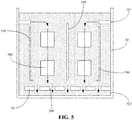
- the dotted arrows in the figures indicate the flow direction of the cooling medium in the state of a hot liquid fluid
- the solid arrows indicate the flow direction of the cooling medium in the state of a cold liquid fluid.
- the cooling cabinet 1 of the present specification is provided with a plurality of plug-in components 190 for installing the to-be-cooled devices 900, and the to-be-cooled devices 900 may each be of a sheet-type structure and are plugged in these plug-in components 190 one by one.
- the cooling medium 80 After entering the first diversion assembly 20 from the first diversion inlet 101 of the cabinet body 10, the cooling medium 80 is discharged into the cabinet body 10 through the second diversion outlet 200 of the first diversion assembly 20 and then flows up through the to-be-cooled devices 900; the cooling medium 80 flowing through the to-be-cooled device 900 takes away the heat of the to-be-cooled device 900, and then enters the second diversion assembly 30 through the second diversion inlet 300 of the second diversion assembly 30, and finally is discharged out of the cabinet body 10 through the first diversion outlet 102 of the cabinet body 10. In this way, the purpose of dissipating the heat of the to-be-cooled device 900 is achieved.
- the dotted arrows in the figures indicate the flow direction of the cooling medium in the state of a hot liquid fluid
- the solid arrows indicate the flow direction of the cooling medium in the state of a cold liquid fluid.
- An embodiment of the present specification further provides a cooling cabinet for cooling a to-be-cooled device.
- the cooling cabinet includes a cabinet body and a diversion assembly disposed in the cabinet body, and the diversion assembly is provided with a plurality of discretely distributed diversion openings.
- the cabinet body may contain a cooling medium for at least partially immersing the to-be-cooled device, and the cabinet body is provided with a first diversion inlet for introducing the cooling medium and a first diversion outlet for discharging the cooling medium.
- the diversion assembly is provided in communication with the diversion inlet, and the plurality of diversion openings are configured to discharge the cooling medium into the cabinet body; or the diversion assembly is provided in communication with the diversion outlet, and the plurality of diversion openings are configured to introduce the cooling medium flowing through the to-be-cooled device.
- the diversion assembly may be provided in communication with the diversion inlet of the cabinet body, thus introducing the cooling medium.
- the diversion assembly may also be provided in communication with the diversion outlet of the cabinet body to discharge the cooling medium.
- the plurality of diversion openings that are discretely distributed can make the cooling medium flow into or out of the cabinet body from multiple different directions, reducing the temperature difference between the cooling mediums, thereby making the flow and temperature of the cooling medium more uniform and achieving higher cooling efficient.
- the diversion assembly when the diversion assembly is provided in communication with the diversion inlet, the diversion assembly functions as the first diversion assembly described in Embodiment 1, and the diversion openings function as the second diversion outlet described in Embodiment 1; in this case, for the structure of the diversion assembly, reference may be made to the description of the first diversion assembly in Embodiment 1.
- the diversion assembly when the diversion assembly is provided in communication with the diversion outlet, the diversion assembly functions as the second diversion assembly described in Embodiment 1, and the diversion openings function as the second diversion inlet described in Embodiment 1; in this case, for the structure of the diversion assembly, reference may be made to the description of the second diversion assembly in Embodiment 1.
- An embodiment of the present specification further provides a cooling system, including the cooling cabinet as described in Embodiment 1 or Embodiment 2 above and a heat exchanging device connected to the cooling cabinet. It should be noted that the description of the cooling cabinet in the Embodiments 1 and 2 above is also applicable to the cooling system of the present specification. The cooling system described in Embodiment 1 is taken as an example to describe the cooling system of the present specification.
- the cooling system 2 of the present specification includes the cooling cabinet 1 described in Embodiment 1 and a heat exchanging device 3 connected to the cooling cabinet 1.
- One end of the heat exchanging device 3 is provided in communication with the cabinet body 10 of the cooling cabinet 1, and the other end of the heat exchanging device 3 is provided in communication with an external liquid supply device.
- the heat exchanging device 3 is configured to drive the cooling medium to circulate in the cabinet body 10 of the cooling cabinet 1 and exchange heat with the cooling medium.
- the cooling system 2 of the present specification drives the cooling medium to circulate in the cooling cabinet 1 through the heat exchanging device 3 to take away the heat of the to-be-cooled device 900, and exchanges heat with the external liquid supply device through the heat exchanging device 3, so that the cooling medium reaches a low temperature state again, and circulates into the cooling cabinet 1 to cool the to-be-cooled device 900 again, thus achieving the purpose of circularly and continuously cooling the to-be-cooled device 900.
- the heat exchanging device 3 includes a heat exchanger 40 and a pump 50.
- the heat exchanger 40 is connected to the cooling cabinet 1 through a first circulation loop, and is connected to the external liquid supply device through a second circulation loop.
- the first circulation loop includes a first pipeline 510 and a second pipeline 520, and the second circulation loop includes a third pipeline 530 and a fourth pipeline 540.
- the first pipeline 510 is provided in communication with the first diversion inlets 101 of the cooling cabinet 1
- the second pipeline 520 is provided in communication with the first diversion outlets 102 of the cooling cabinet 1
- the third pipeline 530 and the fourth pipeline 540 are both provided in communication with the external liquid supply device.
- the pump 50 drives the cooling medium to circulate in the cooling cabinet 1 through the first circulation loop, and the cooling medium takes away the heat of the to-be-cooled device 900 through the circulation in the cooling cabinet 1 and enters the heat exchanger 40 of the heat exchanging device 3.
- the external liquid supply device can circulate cooling water in the second circulation loop, and the cooling system carrying the heat of the to-be-cooled device 900 may exchanges heat in the heat exchanger 40 with the cooling water provided by the external liquid supply device to discharge the heat carried by the cooling system, so that the cooling medium reaches a low temperature state again, and circulates into the cooling cabinet 1 to cool the to-be-cooled device 900 again, thus achieving the purpose of circularly and continuously cooling the to-be-cooled device 900.
Landscapes
- Engineering & Computer Science (AREA)
- Microelectronics & Electronic Packaging (AREA)
- Physics & Mathematics (AREA)
- Thermal Sciences (AREA)
- Computer Hardware Design (AREA)
- General Engineering & Computer Science (AREA)
- Cooling Or The Like Of Electrical Apparatus (AREA)
- Cooling Or The Like Of Semiconductors Or Solid State Devices (AREA)
Abstract
Description
- The present application claims the priority of Chinese Patent Application No.
201711073039.6 - The present specification relates to the technical field of cooling devices, and in particular, to a cooling cabinet and a cooling system.
- With the rapid development of cloud computing technology (i.e., large-scale distributed system technology), the requirements for computing performance of servers are getting increasingly higher. While server performance is improving, power consumption is increasing rapidly, and the power consumption of the cabinet has increased exponentially. The data shows that the power density of data center cabinets has increased by nearly 15 times in the past decade. In the past, the power consumption of a cabinet was generally 1.5 kW-2 kW. However, some cabinets have partially reached as high as 20 kW-30 kW.
- At present, servers in data centers usually adopt the way of air conditioning and air cooling, which are consuming a large amount of energy, space and cost, and the consumption is increasing. However, with the steady increase in power density, the cooling capacity provided by many data centers is currently approaching the limit, and this trend of rapid increase in power density will have an adverse effect. Therefore, the conventional way of air conditioning and air cooling has been unable to meet the cooling demand of the servers in the data centers.
- The present specification provides a cooling cabinet and a cooling system to improve the cooling efficiency for the servers in a data center.
- According to a first aspect of the embodiments of the present specification, provided is a cooling cabinet for cooling a to-be-cooled device, and the cooling cabinet includes a cabinet body, a first diversion assembly and a second diversion assembly;
wherein the cabinet body may contain a cooling medium for at least partially immersing the to-be-cooled device, and the cabinet body is provided with a first diversion inlet for introducing the cooling medium and a first diversion outlet for discharging the cooling medium; the first diversion assembly is provided in communication with the first diversion inlet, and the first diversion assembly is provided with a second diversion outlet for discharging the cooling medium into the cabinet body; the second diversion assembly is provided in communication with the first diversion outlet, and the second diversion assembly is provided with a second diversion inlet for introducing the cooling medium flowing through the to-be-cooled device. - Further, the first diversion inlet is located above the first diversion outlet; the first diversion assembly is located at the top of the to-be-cooled device, and the second diversion assembly is located at the bottom of the to-be-cooled device.
- Further, the first diversion inlet is located below the first diversion outlet; the first diversion assembly is located at the bottom of the to-be-cooled device, and the second diversion assembly is located at the top of the to-be-cooled device.
- Further, the first diversion assembly includes a loop tube portion and a first diversion portion provided in communication with the loop tube portion, the first diversion portion is provided in communication with the first diversion inlet, and at least one of the loop tube portion and the first diversion portion is provided with the second diversion outlet.
- Further, the loop tube portion is a rectangular loop tube structure and includes two first tube bodies and two second tube bodies which communicate with each other and are connected into an enclosure; the first diversion portion is provided in communication with any of the first tube bodies, and at least one of the first tube bodies, the second tube bodies, and the first diversion portion is provided with the second diversion outlet.
- Further, there are two first diversion inlets, which are respectively disposed on two sides of the cabinet body; there are two first diversion portions which communicate with the two first tube bodies in one-to-one correspondence.
- Further, each of the two first tube bodies is integrally formed with at least one of the adjacent second tube bodies.
- Further, there are a plurality of second diversion outlets, which are evenly arranged on a side wall of at least one of the first tube bodies, the second tube bodies, and the first diversion portions.
- Further, the second diversion assembly includes a tube bank portion and a second diversion portion provided in communication with the tube bank portion, the second diversion portion is provided in communication with the first diversion outlet, and the tube bank portion is provided with the second diversion inlet.
- Further, the tube bank portion is a rectangular tube bank structure and includes two third tube bodies and a plurality of fourth tube bodies connected between the two third tube bodies; the plurality of fourth tube bodies are provided in communication with the two third tube bodies; the second diversion portion is provided in communication with any of the third tube bodies, and the fourth tube bodies are provided with the second diversion inlets.
- Further, there are two first diversion outlets, which are respectively disposed on two sides of the cabinet body; there are two second diversion portions which communicate with the two third tube bodies in one-to-one correspondence.
- Further, the plurality of fourth tube bodies include two groups arranged in a staggered manner; one group of the fourth tube bodies and one of the third tube bodies are integrally formed, and the other group of the fourth tube bodies and the other third tube body are integrally formed.
- Further, there are a plurality of the second diversion inlets, which are evenly arranged at the top of the fourth tube bodies.
- According to a second aspect of the embodiments of the present specification, provided is a cooling system, including a cooling cabinet and a heat exchanging device, wherein the cooling cabinet is configured to cool a to-be-cooled device and includes a cabinet body, a first diversion assembly and a second diversion assembly which are disposed in the cabinet body, and the first diversion assembly and the second diversion assembly are respectively located at two sides of the to-be-cooled device;
wherein the cabinet body may contain a cooling medium for at least partially immersing the to-be-cooled device, and the cabinet body is provided with a first diversion inlet for introducing the cooling medium and a first diversion outlet for discharging the cooling medium; the first diversion assembly is provided in communication with the first diversion inlet, and the first diversion assembly is provided with a second diversion outlet for discharging the cooling medium into the cabinet body; the second diversion assembly is provided in communication with the first diversion outlet, and the second diversion assembly is provided with a second diversion inlet for introducing the cooling medium flowing through the to-be-cooled device;
one end of the heat exchanging device is provided in communication with the cabinet body, and the other end of the heat exchanging device is provided in communication with an external liquid supply device. The heat exchanging device is configured to drive the cooling medium to circulate in the cabinet body and exchange heat with the cooling medium. - According to a third aspect of the embodiments of the present specification, provided is a cooling cabinet for cooling a to-be-cooled device. The cooling cabinet includes a cabinet body and a diversion assembly disposed in the cabinet body; the diversion assembly is provided with a plurality of discretely distributed diversion openings; the cabinet body may contain a cooling medium for at least partially immersing the to-be-cooled device, and the cabinet body is provided with a diversion inlet for introducing the cooling medium and a diversion outlet for discharging the cooling medium;
the diversion assembly is provided in communication with the diversion inlet, and the plurality of diversion openings are configured to discharge the cooling medium into the cabinet body; or the diversion assembly is provided in communication with the diversion outlet, and the plurality of diversion openings are configured to introduce the cooling medium flowing through the to-be-cooled device. - Further, the diversion assembly includes a loop tube portion and a first diversion portion provided in communication with the loop tube portion, the first diversion portion is provided in communication with the first diversion inlet, and at least one of the loop tube portion and the first diversion portion is provided with the plurality of diversion openings.
- Further, the loop tube portion is a rectangular loop tube structure and includes two first tube bodies and two second tube bodies which communicate with each other and are connected into an enclosure; the first diversion portion is provided in communication with any of the first tube bodies, and at least two of the first tube bodies, the second tube bodies, and the first diversion portion are provided with the plurality of diversion openings.
- Further, the diversion assembly includes a tube bank portion and a second diversion portion provided in communication with the tube bank portion, the second diversion portion is provided in communication with the diversion outlet, and the tube bank portion is provided with the plurality of diversion openings.
- Further, the tube bank portion is a rectangular tube bank structure and includes two third tube bodies and a plurality of fourth tube bodies connected between the two third tube bodies; the plurality of fourth tube bodies are provided in communication with the two third tube bodies; the second diversion portion is provided in communication with any of the third tube bodies, and the fourth tube bodies are provided with the plurality of diversion openings.
- According to a fourth aspect of the embodiments of the present specification, provided is a cooling system, including a cooling cabinet and a heat exchanging device, wherein the cooling cabinet is configured to cool a to-be-cooled device and includes a cabinet body and a diversion assembly disposed in the cabinet body, and the diversion assembly is provided with a plurality of discretely distributed diversion openings;
wherein the cabinet body may contain a cooling medium for at least partially immersing the to-be-cooled device, and the cabinet body is provided with a first diversion inlet for introducing the cooling medium and a first diversion outlet for discharging the cooling medium;
the diversion assembly is provided in communication with the diversion inlet, and the plurality of diversion openings are configured to discharge the cooling medium into the cabinet body; or the diversion assembly is provided in communication with the diversion outlet, and the plurality of diversion openings are configured to introduce the cooling medium flowing through the to-be-cooled device;
one end of the heat exchanging device is provided in communication with the cabinet body, and the other end of the heat exchanging device is provided in communication with an external liquid supply device. The heat exchanging device is configured to drive the cooling medium to circulate in the cabinet body and exchange heat with the cooling medium. - As can be seen from the above technical solutions, in the cooling cabinet of the present specification, by arranging the first diversion assembly and the second diversion assembly on two opposite sides of the to-be-cooled device, the flow field of the cooling medium flowing through the to-be-cooled device is a straight path, so that the entire liquid flow path of the cooling medium is the shortest, the resistance is the smallest, and the energy consumption required to drive the liquid is correspondingly greatly reduced, thereby achieving the effect of minimum energy consumption. Since a plurality of diversion openings are disposed in a discrete distribution on the diversion assembly, the diversion assembly may be provided in communication with the diversion inlets of the cabinet body, thus introducing the cooling medium. The plurality of diversion openings that are discretely distributed can make the cooling medium flow into or out of the cabinet body from multiple different directions, reducing the temperature difference between the cooling mediums, thereby making the flow and temperature of the cooling medium more uniform and achieving higher cooling efficient. The cooling system drives the cooling medium to circulate in the cooling cabinet through the heat exchanging device to take away the heat of the to-be-cooled device, and exchanges heat with the external liquid supply device through the heat exchanging device, so that the cooling medium reaches a low temperature state again, and circulates into the cooling cabinet to cool the to-be-cooled device again, thus achieving the purpose of circularly and continuously cooling the to-be-cooled device.
-
-
FIG. 1 is a schematic perspective view of a cooling cabinet according to an exemplary embodiment of the present disclosure; -
FIG. 2 is a schematic perspective view of a cooling cabinet according to an exemplary embodiment of the present disclosure, with a cover removed; -
FIG. 3 is a schematic perspective view of a cooling cabinet according to an exemplary embodiment of the present disclosure, with a cover and a cabinet body removed; -
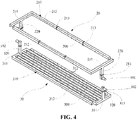
FIG. 4 is a schematic perspective view of a first diversion assembly and a second diversion assembly in a cooling cabinet according to an exemplary embodiment of the present disclosure; -
FIG. 5 is a schematic view of a flow field of a cooling cabinet according to an exemplary embodiment of the present disclosure; -
FIG. 6 is a schematic view of a flow field of another cooling cabinet according to an exemplary embodiment of the present disclosure; and -
FIG. 7 is a schematic structural diagram of a cooling system according to an exemplary embodiment of the present specification. - Exemplary embodiments will be described in detail herein, examples of which are illustrated in figures. When the following description refers to figures, same numerals in different figures refer to the same or similar elements, unless otherwise indicated. The implementations described in the following exemplary embodiments do not represent all implementations consistent with the present specification. Instead, they are merely examples of devices and methods consistent with some aspects, as detailed in the appended claims, of the present specification.
- The terminology used in the present specification is for the purpose of describing specific embodiments, but not intended to limit the present specification. The singular forms "a", "said" and "the" as used in the present specification and the appended claims are also intended to include plural forms unless otherwise other meanings are explicitly indicated in the context. It also should be understood that the term "and/or" as used herein refers to encompassing any or all possible combinations of one or more associated listed items.
- It should be understood that although the terms "first", "second", "third", etc. may be used in the present specification to describe various types of information, such information should not be limited to these terms. These terms are only used to distinguish the same type of information from each other. For example, first information may also be referred to as second information without departing from the scope of the present specification. Similarly, the second information may also be referred to as the first information. It depends on the context; for example, the word "if" as used herein may be interpreted as "at the time of" or "when" or "in response to a determination".
- The present specification provides a cooling cabinet and a cooling system to improve the cooling efficiency for the servers in a data center. The cooling cabinet and the cooling system of the present specification will be described in detail below with reference to the drawings. In the case of no conflict, the features in the following embodiments and implementations may be combined with each other.
- Referring to
FIG. 1 to FIG. 4 , an embodiment of the present specification provides a cooling cabinet 1 adopting a single-phase immersion liquid cooling technology for cooling a to-be-cooled device 900. The to-be-cooled device 900 may be a server in a data center, or may be other heating devices that need to be cooled. The cooling cabinet 1 includes acabinet body 10, afirst diversion assembly 20 and asecond diversion assembly 30. Thecabinet body 10 may contain a non-conductive cooling medium for at least partially immersing the to-be-cooled device 900, and thecabinet body 10 is provided with afirst diversion inlet 101 for introducing the cooling medium and afirst diversion outlet 102 for discharging the cooling medium. Thefirst diversion assembly 20 is provided in communication with thefirst diversion inlet 101, and thefirst diversion assembly 20 is provided with asecond diversion outlet 200 for discharging the cooling medium into thecabinet body 10; after flowing through the to-be-cooled device 900, the cooling medium can cool the to-be-cooled device 900. Thesecond diversion assembly 30 is provided in communication with thefirst diversion outlet 102, and thesecond diversion assembly 30 is provided with asecond diversion inlet 300 for introducing the cooling medium flowing through the to-be-cooled device 900. Optionally, thefirst diversion assembly 20 and thesecond diversion assembly 30 are both disposed in thecabinet body 10, and thefirst diversion assembly 20 and thesecond diversion assembly 30 are respectively located on two sides of the to-be-cooled device. In the example shown in the figures, thefirst diversion assembly 20 and thesecond diversion assembly 30 are respectively located on two sides of the to-be-cooled device in the vertical direction, so that the flow field of the cooling medium is a straight path in the vertical direction, which can avoid extra energy consumption due to gravity when the cooling medium moves in the lateral direction. It should be noted that the cooling medium may completely immerse the to-be-cooled device 900, or may partially immerse the to-be-cooled device 900, which may be set according to actual needs. The cooling medium may be a gaseous medium, a liquid medium, or a solid-liquid mixed medium, which may also be set according to actual needs. In this embodiment, the cooling medium completely immerses the to-be-cooled device 900, and the cooling medium is a liquid 3M electronic fluorinated liquid. The cooling medium is discharged into thecabinet body 10 through thefirst diversion assembly 20, and the cooling medium flowing through the to-be-cooled device 900 is discharged out of thecabinet body 10 through thesecond diversion assembly 30. However, in other embodiments, it is also feasible that thefirst diversion assembly 20 is provided in communication with thefirst diversion outlet 102, and thesecond diversion assembly 30 is provided in communication with thefirst diversion inlet 101. The setting is equivalent to introducing the cooling medium into thecabinet body 10 through thesecond diversion assembly 30, and discharging the cooling medium flowing through the to-be-cooled device 900 out of thecabinet body 10 through thefirst diversion assembly 20. - As can be seen from the above technical solution, in the cooling cabinet 1 of the present specification, the cooling medium enters the
cabinet body 10 from thefirst diversion inlet 101 of thecabinet body 10 and is then discharged to the to-be-cooled device 900 through thesecond diversion outlet 200 of thefirst diversion assembly 20; the cooling medium flowing through the to-be-cooled device 900 takes away the heat of the to-be-cooled device 900, and then enters thesecond diversion assembly 30 through thesecond diversion inlet 300 of thesecond diversion assembly 30, and finally is discharged out of thecabinet body 10 through thefirst diversion outlet 102 of thecabinet body 10. In this way, the purpose of dissipating the heat of the to-be-cooled device 900 is achieved. By arranging thefirst diversion assembly 20 and thesecond diversion assembly 30 on two opposite sides of the to-be-cooled device 900, the flow field of the cooling medium flowing through the to-be-cooled device 900 is a straight path, so that the entire liquid flow path of the cooling medium is the shortest, the resistance is the smallest, and the energy consumption required to drive the liquid is correspondingly greatly reduced, thereby achieving the effect of minimum energy consumption. In addition, the cooling medium flows along a linear flow path, and cold and hot fluids are completely isolated, which can prevent the cold and hot fluids from mixing with each other, thereby achieving the optimal cooling effect. - As shown in
FIG. 1 , in an optional implementation, acover 100 is detachably disposed at the top of thecabinet body 10 through fasteners. When the to-be-cooled device 900 needs to be placed in thecabinet body 10, the fasteners are removed to open thecover 100, and the to-be-cooled device 900 then can be placed in thecabinet body 10. After the to-be-cooled device 900 is placed in thecabinet body 10, thecover 100 is closed to seal thecabinet body 10. - Referring to
FIGS. 2 and3 , in an optional implementation, thefirst diversion inlet 101 are located above thefirst diversion outlet 102. Accordingly, thefirst diversion assembly 20 is located at the top of the to-be-cooled device 900, and thesecond diversion assembly 30 is located at the bottom of the to-be-cooled device 900. However, in another optional implementation, thefirst diversion inlet 101 may be located below thefirst diversion outlet 102. Accordingly, thefirst diversion assembly 20 is located at the bottom of the to-be-cooled device 900, and thesecond diversion assembly 30 is located at the top of the to-be-cooled device 900. The flow field of the cooling medium flowing through the to-be-cooled device 900 may have a straight path directly from top to bottom or from bottom to top, so that the entire liquid flow path of the cooling medium is the shortest and the resistance is the smallest. - Referring to
FIG. 4 , in an optional implementation, thefirst diversion assembly 20 includes aloop tube portion 210 and afirst diversion portion 220 provided in communication with theloop tube portion 210, thefirst diversion portion 220 is provided in communication with thefirst diversion inlet 101, and at least one of theloop tube portion 210 and thefirst diversion portion 220 is provided with thesecond diversion outlet 200. In this embodiment, theloop tube portion 210 and thefirst diversion portion 220 are both provided with thesecond diversion outlet 200. After entering thefirst diversion assembly 20 from thefirst diversion inlet 101 of thecabinet body 10, the cooling medium is discharged into thecabinet body 10 through thesecond diversion outlet 200 disposed in theloop tube portion 210 and thefirst diversion portion 220 and then flows through the to-be-cooled device 900 to cool the to-be-cooled device 900. - Further, the loop structure of the
loop tube portion 210 may correspond to the cross-sectional structure of the to-be-cooled device 900, so that the cooling medium flowing out of thefirst diversion assembly 20 can flow along the periphery of the to-be-cooled device 900 to achieve higher cooling efficiency. For example, the cross-sectional structure of the to-be-cooled device 900 is rectangular, and theloop tube portion 210 is a rectangular loop tube structure corresponding to the cross-sectional structure. However, the cross-sectional structure of the to-be-cooled device 900 may also be other shapes, and it is required that the loop structure of theloop tube portion 210 corresponds to the cross-sectional structure. - In an optional implementation, the cross-sectional structure of the to-
be-cooled device 900 is rectangular, and theloop tube portion 210 is a rectangular loop tube structure corresponding to the the cross-sectional structure. Theloop tube portion 210 includes twofirst tube bodies 211 and twosecond tube bodies 212 which communicate with each other and are connected into an enclosure; thefirst diversion portion 220 is provided in communication with any of thefirst tube bodies 211, and at least one of thefirst tube bodies 211, thesecond tube bodies 212, and thefirst diversion portion 220 is provided with thesecond diversion outlets 200 in the side wall. In this embodiment, the inner walls of thefirst tube bodies 211, thefirst tube bodies 212 and thefirst diversion portion 220 are all provided with thesecond diversion outlets 200. After entering thefirst diversion assembly 20 from thefirst diversion inlet 101 of thecabinet body 10, the cooling medium is discharged into thecabinet body 10 through thesecond diversion outlet 200 disposed in thefirst tube bodies 211, thesecond tube bodies 212 and thefirst diversion portion 220 and then flows through the to-be-cooled device 900 to cool the to-be-cooled device 900. - In an optional implementation, there are two
first diversion inlets 101 disposed on two sides of thecabinet body 10 respectively. Correspondingly, there are twofirst diversion portions 220 which communicate with the twofirst tube bodies 211 in one-to-one correspondence. In this way, the circulation speed of the cooling medium can be increased, and further the cooling efficiency of the to-be-cooled device 900 can be improved. - In an optional implementation, the length of the
first tube body 211 is shorter than the length of thesecond tube body 212; a reinforcingring 213 is fitted on thefirst tube body 211, and a plurality of reinforcingrings 213 are fitted on thesecond tube body 212 at intervals, which can enhance the structural strength of thefirst diversion assembly 20. Further, each of the twofirst tube bodies 211 is integrally formed with at least one of the adjacentsecond tube bodies 212. That is, each of the twofirst tube bodies 211 may be formed integrally with the corresponding one of the twosecond tube bodies 212, or the twofirst tube bodies 211 and the twosecond tube bodies 212 are integrally formed respectively, which can further enhance the structural strength of thefirst diversion assembly 20. It should be noted that term "a plurality of' used herein refers to two or more. - In an optional implementation, the
second diversion assembly 30 includes atube bank portion 310 and asecond diversion portion 320 provided in communication with thetube bank portion 310, thesecond diversion portion 320 is provided in communication with thefirst diversion outlet 102, and thetube bank portion 310 is provided with thesecond diversion inlet 300. The cooling medium flowing through the to-be-cooled device 900 takes away the heat of the to-be-cooled device 900, and then enters thesecond diversion assembly 30 through thesecond diversion inlet 300 disposed on thetube bank portion 310, and finally is discharged out of thecabinet body 10 through thefirst diversion outlet 102 of thecabinet body 10. In this way, the purpose of dissipating the heat of the to-be-cooled device 900 is achieved. - Further, the tube bank structure of the
tube bank portion 310 may correspond to the cross-sectional structure of the to-be-cooled device 900, so that the cooling medium flowing through the to-be-cooled device 900 can flow into thesecond diversion assembly 30 as much as possible and then is discharged from thefirst diversion outlet 102 of thecabinet body 10, thereby increasing the circulation speed of the cooling medium. For example, the cross-sectional structure of the to-be-cooled device 900 is rectangular, and the tube bank structure of thetube bank portion 310 is a rectangular tube bank structure corresponding to the cross-sectional structure. However, the cross-sectional structure of the to-be-cooled device 900 may also be other shapes, and it is required that the tube bank structure of thetube bank portion 310 corresponds to the cross-sectional structure. - In an optional implementation, the cross-sectional structure of the to-
be-cooled device 900 is rectangular, and thetube bank portion 310 is a rectangular tube bank structure corresponding to the the cross-sectional structure. Thetube bank portion 310 includes twothird tube bodies 311 and a plurality offourth tube bodies 312 connected between the twothird tube bodies 311. The plurality offourth tube bodies 312 are all provided in communication with the twothird tube bodies 311. Thesecond diversion portion 320 is provided in communication with any one of thethird tube bodies 311, and thesecond diversion inlets 300 are disposed at the top of thefourth tube bodies 312. The cooling medium flowing through the to-be-cooled device 900 takes away the heat of the to-be-cooled device 900, and then enters thesecond diversion assembly 30 through thesecond diversion inlets 300 disposed on thefourth tube bodies 312, and finally is discharged out of thecabinet body 10 through thefirst diversion outlet 102 of thecabinet body 10. In this way, the purpose of dissipating the heat of the to-be-cooled device 900 is achieved. - In an optional implementation, there are two
first diversion outlets 102 disposed on two sides of thecabinet body 10 respectively. Correspondingly, there are twosecond diversion portions 320 which communicate with the twothird tube bodies 311 in one-to-one correspondence. In this way, the circulation speed of the cooling medium can be increased, and further the cooling efficiency of the to-be-cooled device 900 can be improved. - In an optional implementation, the length of the
third tube body 311 is shorter than the length of thefourth tube body 312; a reinforcingring 313 is fitted on thethird tube body 311, which can enhance the structural strength of thesecond diversion assembly 30. Optionally, the plurality offourth tube bodies 312 include two groups arranged in a staggered manner. One group of thefourth tube bodies 312 and one of thethird tube bodies 311 are integrally formed, and the other group of thefourth tube bodies 312 and the otherthird tube body 311 are integrally provided; that is, the plurality offourth tubes bodies 312 and the twothird tube bodies 311 form an integrated structure of two rakes, which can further enhance the structural strength of thesecond diversion assembly 30. - In an optional implementation, there are a plurality of
second diversion outlets 200, and the plurality ofsecond diversion outlets 200 are evenly arranged on at least one of thefirst tube bodies 211, thesecond tube bodies 212, and thefirst diversion portion 220 of thefirst diversion assembly 20. In the embodiment shown in the figure, the inner walls of thefirst tube bodies 211, thesecond tube bodies 212, and thefirst diversion portion 220 of thefirst diversion assembly 20 are all provided with a plurality of evenly arrangedsecond diversion outlets 200. There are a plurality ofsecond diversion inlets 300, and the plurality ofsecond diversion inlets 300 are evenly arranged at the top of thefourth tube bodies 312 of thesecond diversion assembly 30. In this way, the cooling medium may flow through the to-be-cooled device 900 more evenly, which is beneficial to improving the cooling efficiency. - With reference to
FIGS 3-5 which show an example where thefirst diversion inlet 101 is located above thefirst diversion outlet 102, thefirst diversion assembly 20 is located at the top of the to-be-cooled device 900, and thesecond diversion assembly 30 is located at the bottom of the to-be-cooled device 900, the working principle of the cooling cabinet 1 in the present specification will be described. The cooling cabinet 1 of the present specification is provided with a plurality of plug-incomponents 190 for installing the to-be-cooled devices 900, and the to-be-cooled devices 900 may each be of a sheet-type structure and are plugged in these plug-incomponents 190 one by one. After entering thefirst diversion assembly 20 from thefirst diversion inlet 101 of thecabinet body 10, the cooling medium 80 is discharged into thecabinet body 10 through thesecond diversion outlet 200 of thefirst diversion assembly 20 and then flows down through the to-be-cooled devices 900; the cooling medium 80 flowing through the to-be-cooled device 900 takes away the heat of the to-be-cooled device 900, and then enters thesecond diversion assembly 30 through thesecond diversion inlet 300 of thesecond diversion assembly 30, and finally is discharged out of thecabinet body 10 through thefirst diversion outlet 102 of thecabinet body 10. In this way, the purpose of dissipating the heat of the to-be-cooled device 900 is achieved. The dotted arrows in the figures indicate the flow direction of the cooling medium in the state of a hot liquid fluid, and the solid arrows indicate the flow direction of the cooling medium in the state of a cold liquid fluid. By arranging thefirst diversion assembly 20 at the top of the to-be-cooled device 900 and arranging thesecond diversion assembly 30 at the bottom of the to-be-cooled device 900, the flow field of the cooling medium 80 flowing through the to-be-cooled device 900 is a straight path from top to bottom, so that the entire liquid flow path of the cooling medium is the shortest, the resistance is the smallest, and the energy consumption required to drive the liquid is correspondingly greatly reduced, thereby achieving the effect of minimum energy consumption. In addition, the cooling medium flows along a linear flow path, and cold and hot fluids are completely isolated, which can prevent the cold and hot fluids from mixing with each other, thereby achieving the optimal cooling effect. - Referring to
FIG. 6 which shows an example where thefirst diversion inlet 101 is located below thefirst diversion outlet 102, thefirst diversion assembly 20 is located at the bottom of the to-be-cooled device 900, and thesecond diversion assembly 30 is located at the top of the to-be-cooled device 900, the working principle of the cooling cabinet 1 in the present specification will be described. The cooling cabinet 1 of the present specification is provided with a plurality of plug-incomponents 190 for installing the to-be-cooled devices 900, and the to-be-cooled devices 900 may each be of a sheet-type structure and are plugged in these plug-incomponents 190 one by one. After entering thefirst diversion assembly 20 from thefirst diversion inlet 101 of thecabinet body 10, the cooling medium 80 is discharged into thecabinet body 10 through thesecond diversion outlet 200 of thefirst diversion assembly 20 and then flows up through the to-be-cooled devices 900; the cooling medium 80 flowing through the to-be-cooled device 900 takes away the heat of the to-be-cooled device 900, and then enters thesecond diversion assembly 30 through thesecond diversion inlet 300 of thesecond diversion assembly 30, and finally is discharged out of thecabinet body 10 through thefirst diversion outlet 102 of thecabinet body 10. In this way, the purpose of dissipating the heat of the to-be-cooled device 900 is achieved. The dotted arrows in the figures indicate the flow direction of the cooling medium in the state of a hot liquid fluid, and the solid arrows indicate the flow direction of the cooling medium in the state of a cold liquid fluid. By arranging thefirst diversion assembly 20 at the bottom of the to-be-cooled device 900 and arranging thesecond diversion assembly 30 at the top of the to-be-cooled device 900, the flow field of the cooling medium 80 flowing through the to-be-cooled device 900 is a straight path from bottom to top, so that the entire liquid flow path of the cooling medium is the shortest, the resistance is the smallest, and the energy consumption required to drive the liquid is correspondingly greatly reduced, thereby achieving the effect of minimum energy consumption. In addition, the cooling medium flows along a linear flow path, and cold and hot fluids are completely isolated, which can prevent the cold and hot fluids from mixing with each other, thereby achieving the optimal cooling effect. - An embodiment of the present specification further provides a cooling cabinet for cooling a to-be-cooled device. The cooling cabinet includes a cabinet body and a diversion assembly disposed in the cabinet body, and the diversion assembly is provided with a plurality of discretely distributed diversion openings. The cabinet body may contain a cooling medium for at least partially immersing the to-be-cooled device, and the cabinet body is provided with a first diversion inlet for introducing the cooling medium and a first diversion outlet for discharging the cooling medium. The diversion assembly is provided in communication with the diversion inlet, and the plurality of diversion openings are configured to discharge the cooling medium into the cabinet body; or the diversion assembly is provided in communication with the diversion outlet, and the plurality of diversion openings are configured to introduce the cooling medium flowing through the to-be-cooled device.
- As can be seen from the above technical solutions, in the cooling cabinet of the present description, since a plurality of diversion openings are disposed in a discrete distribution on the diversion assembly, the diversion assembly may be provided in communication with the diversion inlet of the cabinet body, thus introducing the cooling medium. The diversion assembly may also be provided in communication with the diversion outlet of the cabinet body to discharge the cooling medium. However, no matter which arrangement the present specification discloses, the plurality of diversion openings that are discretely distributed can make the cooling medium flow into or out of the cabinet body from multiple different directions, reducing the temperature difference between the cooling mediums, thereby making the flow and temperature of the cooling medium more uniform and achieving higher cooling efficient.
- It should be noted that, when the diversion assembly is provided in communication with the diversion inlet, the diversion assembly functions as the first diversion assembly described in Embodiment 1, and the diversion openings function as the second diversion outlet described in Embodiment 1; in this case, for the structure of the diversion assembly, reference may be made to the description of the first diversion assembly in Embodiment 1. When the diversion assembly is provided in communication with the diversion outlet, the diversion assembly functions as the second diversion assembly described in Embodiment 1, and the diversion openings function as the second diversion inlet described in Embodiment 1; in this case, for the structure of the diversion assembly, reference may be made to the description of the second diversion assembly in Embodiment 1.
- An embodiment of the present specification further provides a cooling system, including the cooling cabinet as described in Embodiment 1 or Embodiment 2 above and a heat exchanging device connected to the cooling cabinet. It should be noted that the description of the cooling cabinet in the Embodiments 1 and 2 above is also applicable to the cooling system of the present specification. The cooling system described in Embodiment 1 is taken as an example to describe the cooling system of the present specification.
- Referring to
FIG. 7 , the cooling system 2 of the present specification includes the cooling cabinet 1 described in Embodiment 1 and a heat exchanging device 3 connected to the cooling cabinet 1. One end of the heat exchanging device 3 is provided in communication with thecabinet body 10 of the cooling cabinet 1, and the other end of the heat exchanging device 3 is provided in communication with an external liquid supply device. The heat exchanging device 3 is configured to drive the cooling medium to circulate in thecabinet body 10 of the cooling cabinet 1 and exchange heat with the cooling medium. - As can be seen from the above technical solutions, the cooling system 2 of the present specification drives the cooling medium to circulate in the cooling cabinet 1 through the heat exchanging device 3 to take away the heat of the to-
be-cooled device 900, and exchanges heat with the external liquid supply device through the heat exchanging device 3, so that the cooling medium reaches a low temperature state again, and circulates into the cooling cabinet 1 to cool the to-be-cooled device 900 again, thus achieving the purpose of circularly and continuously cooling the to-be-cooled device 900. - In an optional embodiment, the heat exchanging device 3 includes a heat exchanger 40 and a pump 50. The heat exchanger 40 is connected to the cooling cabinet 1 through a first circulation loop, and is connected to the external liquid supply device through a second circulation loop. The first circulation loop includes a first pipeline 510 and a second pipeline 520, and the second circulation loop includes a third pipeline 530 and a fourth pipeline 540. The first pipeline 510 is provided in communication with the
first diversion inlets 101 of the cooling cabinet 1, the second pipeline 520 is provided in communication with thefirst diversion outlets 102 of the cooling cabinet 1, and the third pipeline 530 and the fourth pipeline 540 are both provided in communication with the external liquid supply device. When the cooling system 2 of the present specification is in operation, the pump 50 drives the cooling medium to circulate in the cooling cabinet 1 through the first circulation loop, and the cooling medium takes away the heat of the to-be-cooled device 900 through the circulation in the cooling cabinet 1 and enters the heat exchanger 40 of the heat exchanging device 3. The external liquid supply device can circulate cooling water in the second circulation loop, and the cooling system carrying the heat of the to-be-cooled device 900 may exchanges heat in the heat exchanger 40 with the cooling water provided by the external liquid supply device to discharge the heat carried by the cooling system, so that the cooling medium reaches a low temperature state again, and circulates into the cooling cabinet 1 to cool the to-be-cooled device 900 again, thus achieving the purpose of circularly and continuously cooling the to-be-cooled device 900. - Those skilled in the art will readily conceive of other implementation solutions of the present specification after considering the specification and practicing the invention disclosed herein. The present specification is intended to cover any variations, uses, or adaptations of the present specification. These modifications, uses, or adaptations follow the general principles of the present specification and include the common general knowledge or conventional technical means in the technical field not disclosed in the present specification. The specification and embodiments are considered as exemplary only, with a true scope and spirit of the present specification being indicated by the following claims.
- It should be further noted that the term "include", "comprise" or any other variations thereof are intended to cover non-exclusive inclusions such that a process, method, article, or device that includes a series of elements not only includes those elements but also includes other elements that are not listed explicitly, or also include inherent elements of the process, method, article, or device. In the absence of more limitations, an element defined by the sentence "including a/an..." does not exclude that the process, method, article or device including the element further has other identical elements.
- The embodiments described above are merely preferred embodiments of the present specification and not intended to limit the present specification. Any of modifications, equivalent substitutions, improvements and the like, made within the spirit and principle of the present specification, shall be covered in the scope of the present specification.
Claims (20)
- A cooling cabinet for cooling a to-be-cooled device, wherein the cooling cabinet comprises a cabinet body, a first diversion assembly and a second diversion assembly;
wherein the cabinet body can contain a cooling medium for at least partially immersing the to-be-cooled device, and the cabinet body is provided with a first diversion inlet for introducing the cooling medium and a first diversion outlet for discharging the cooling medium; the first diversion assembly is provided in communication with the first diversion inlet, and the first diversion assembly is provided with a second diversion outlet for discharging the cooling medium into the cabinet body; the second diversion assembly is provided in communication with the first diversion outlet, and the second diversion assembly is provided with a second diversion inlet for introducing the cooling medium flowing through the to-be-cooled device. - The cooling cabinet according to claim 1, wherein the first diversion inlet is located above the first diversion outlet; the first diversion assembly is located at the top of the to-be-cooled device, and the second diversion assembly is located at the bottom of the to-be-cooled device.
- The cooling cabinet according to claim 1, wherein the first diversion inlet is located below the first diversion outlet; the first diversion assembly is located at the bottom of the to-be-cooled device, and the second diversion assembly is located at the top of the to-be-cooled device.
- The cooling cabinet according to claim 2, wherein the first diversion assembly comprises a loop tube portion and a first diversion portion provided in communication with the loop tube portion, the first diversion portion is provided in communication with the first diversion inlet, and at least one of the loop tube portion and the first diversion portion is provided with the second diversion outlet.
- The cooling cabinet according to claim 4, wherein the loop tube portion is a rectangular loop tube structure and comprises two first tube bodies and two second tube bodies which communicate with each other and are connected into an enclosure; the first diversion portion is provided in communication with any of the first tube bodies, and at least one of the first tube bodies, the second tube bodies, and the first diversion portion is provided with the second diversion outlet.
- The cooling cabinet according to claim 5, wherein there are two first diversion inlets, which are respectively disposed on two sides of the cabinet body; there are two first diversion portions which communicate with the two first tube bodies in one-to-one correspondence.
- The cooling cabinet according to claim 5, wherein each of the two first tube bodies is integrally formed with at least one of the adjacent second tube bodies.
- The cooling cabinet according to claim 5, wherein there are a plurality of second diversion outlets, which are evenly arranged on a side wall of at least one of the first tube bodies, the second tube bodies, and the first diversion portions.
- The cooling cabinet according to claim 2, wherein the second diversion assembly comprises a tube bank portion and a second diversion portion provided in communication with the tube bank portion, the second diversion portion is provided in communication with the first diversion outlet, and the tube bank portion is provided with the second diversion inlet.
- The cooling cabinet according to claim 9, wherein the tube bank portion is a rectangular tube bank structure and comprises two third tube bodies and a plurality of fourth tube bodies connected between the two third tube bodies; the plurality of fourth tube bodies are provided in communication with the two third tube bodies; the second diversion portion is provided in communication with any of the third tube bodies, and the fourth tube bodies are provided with the second diversion inlets.
- The cooling cabinet according to claim 10, wherein there are two first diversion outlets, which are respectively disposed on two sides of the cabinet body; there are two second diversion portions which communicate with the two third tube bodies in one-to-one correspondence.
- The cooling cabinet according to claim 10, wherein the plurality of fourth tube bodies include two groups arranged in a staggered manner; one group of the fourth tube bodies and one of the third tube bodies are integrally formed, and the other group of the fourth tube bodies and the other third tube body are integrally formed.
- The cooling cabinet according to claim 10, wherein there are a plurality of the second diversion inlets, which are evenly arranged at the top of the fourth tube bodies.
- A cooling system, comprising a cooling cabinet and a heat exchanging device, wherein the cooling cabinet is configured to cool a to-be-cooled device and comprises a cabinet body, a first diversion assembly and a second diversion assembly which are disposed in the cabinet body, and the first diversion assembly and the second diversion assembly are respectively located at two sides of the to-be-cooled device;
wherein the cabinet body can contain a cooling medium for at least partially immersing the to-be-cooled device, and the cabinet body is provided with a first diversion inlet for introducing the cooling medium and a first diversion outlet for discharging the cooling medium; the first diversion assembly is provided in communication with the first diversion inlet, and the first diversion assembly is provided with a second diversion outlet for discharging the cooling medium into the cabinet body; the second diversion assembly is provided in communication with the first diversion outlet, and the second diversion assembly is provided with a second diversion inlet for introducing the cooling medium flowing through the to-be-cooled device;
one end of the heat exchanging device is provided in communication with the cabinet body, and the other end of the heat exchanging device is provided in communication with an external liquid supply device; the heat exchanging device is configured to drive the cooling medium to circulate in the cabinet body and exchange heat with the cooling medium. - A cooling cabinet for cooling a to-be-cooled device, wherein the cooling cabinet comprises a cabinet body and a diversion assembly disposed in the cabinet body; the diversion assembly is provided with a plurality of discretely distributed diversion openings; the cabinet body can contain a cooling medium for at least partially immersing the to-be-cooled device, and the cabinet body is provided with a diversion inlet for introducing the cooling medium and a diversion outlet for discharging the cooling medium;
the diversion assembly is provided in communication with the diversion inlet, and the plurality of diversion openings are configured to discharge the cooling medium into the cabinet body; or the diversion assembly is provided in communication with the diversion outlet, and the plurality of diversion openings are configured to introduce the cooling medium flowing through the to-be-cooled device. - The cooling cabinet according to claim 15, wherein the diversion assembly comprises a loop tube portion and a first diversion portion provided in communication with the loop tube portion, the first diversion portion is provided in communication with the first diversion inlet, and at least one of the loop tube portion and the first diversion portion is provided with the plurality of diversion openings.
- The cooling cabinet according to claim 16, wherein the loop tube portion is a rectangular loop tube structure and comprises two first tube bodies and two second tube bodies which communicate with each other and are connected into an enclosure; the first diversion portion is provided in communication with any of the first tube bodies, and at least two of the first tube bodies, the second tube bodies, and the first diversion portion are provided with the plurality of diversion openings.
- The cooling cabinet according to claim 15, wherein the diversion assembly comprises a tube bank portion and a second diversion portion provided in communication with the tube bank portion, the second diversion portion is provided in communication with the diversion outlet, and the tube bank portion is provided with the plurality of diversion openings.
- The cooling cabinet according to claim 18, wherein the tube bank portion is a rectangular tube bank structure and comprises two third tube bodies and a plurality of fourth tube bodies connected between the two third tube bodies; the plurality of fourth tube bodies are provided in communication with the two third tube bodies; the second diversion portion is provided in communication with any of the third tube bodies, and the fourth tube bodies are provided with the plurality of diversion openings.
- A cooling system, comprising a cooling cabinet and a heat exchanging device, wherein the cooling cabinet is configured to cool a to-be-cooled device and comprises a cabinet body and a diversion assembly disposed in the cabinet body, and the diversion assembly is provided with a plurality of discretely distributed diversion openings;
wherein the cabinet body can contain a cooling medium for at least partially immersing the to-be-cooled device, and the cabinet body is provided with a first diversion inlet for introducing the cooling medium and a first diversion outlet for discharging the cooling medium;
the diversion assembly is provided in communication with the diversion inlet, and the plurality of diversion openings are configured to discharge the cooling medium into the cabinet body; or the diversion assembly is provided in communication with the diversion outlet, and the plurality of diversion openings are configured to introduce the cooling medium flowing through the to-be-cooled device;
one end of the heat exchanging device is provided in communication with the cabinet body, and the other end of the heat exchanging device is provided in communication with an external liquid supply device; the heat exchanging device is configured to drive the cooling medium to circulate in the cabinet body and exchange heat with the cooling medium.
Applications Claiming Priority (2)
| Application Number | Priority Date | Filing Date | Title |
|---|---|---|---|
| CN201711073039.6A CN109757061B (en) | 2017-11-03 | 2017-11-03 | Cooling cabinet and cooling system |
| PCT/CN2018/111821 WO2019085813A1 (en) | 2017-11-03 | 2018-10-25 | Cooling cabinet and cooling system |
Publications (3)
| Publication Number | Publication Date |
|---|---|
| EP3706523A1 true EP3706523A1 (en) | 2020-09-09 |
| EP3706523A4 EP3706523A4 (en) | 2021-08-11 |
| EP3706523B1 EP3706523B1 (en) | 2025-08-13 |
Family
ID=66332801
Family Applications (1)
| Application Number | Title | Priority Date | Filing Date |
|---|---|---|---|
| EP18873684.7A Active EP3706523B1 (en) | 2017-11-03 | 2018-10-25 | Cooling cabinet and cooling system |
Country Status (6)
| Country | Link |
|---|---|
| US (1) | US11871545B2 (en) |
| EP (1) | EP3706523B1 (en) |
| JP (1) | JP2021501951A (en) |
| CN (1) | CN109757061B (en) |
| TW (1) | TW201924510A (en) |
| WO (1) | WO2019085813A1 (en) |
Cited By (2)
| Publication number | Priority date | Publication date | Assignee | Title |
|---|---|---|---|---|
| EP4010780A4 (en) * | 2020-07-20 | 2023-05-10 | Ivan Kirillov | Fast flow cooling bath for multiprocessor circuit boards |
| WO2023084052A1 (en) | 2021-11-12 | 2023-05-19 | De Klein Christianus Theodorus | System and methods for the individual immersion cooling of hardware components |
Families Citing this family (10)
| Publication number | Priority date | Publication date | Assignee | Title |
|---|---|---|---|---|
| JP6939034B2 (en) * | 2017-04-05 | 2021-09-22 | 富士通株式会社 | Cooling systems, cooling devices, and electronic systems |
| CN111065245B (en) * | 2019-12-29 | 2022-02-22 | 苏州浪潮智能科技有限公司 | Server liquid cooling device |
| WO2022012469A1 (en) * | 2020-07-14 | 2022-01-20 | 北京嘉楠捷思信息技术有限公司 | Immersion-type liquid-cooled heat dissipation system |
| CN113543595B (en) * | 2021-07-12 | 2023-10-27 | 广东合一新材料研究院有限公司 | Mobile immersed servers, workstations and work systems |
| CN113727582A (en) * | 2021-08-20 | 2021-11-30 | 苏州浪潮智能科技有限公司 | Server room and passive immersion heat dissipation system thereof |
| US11889658B2 (en) * | 2021-09-14 | 2024-01-30 | Baidu Usa Llc | Immersion cooling system having dual fluid delivery loops |
| CN114885567A (en) * | 2022-06-14 | 2022-08-09 | 喜动技术有限公司 | Container type computing device with liquid cooling system |
| CN219108016U (en) * | 2022-08-18 | 2023-05-30 | 喜动技术有限公司 | Cooling tank for computing device, cooling device, and container-type computing device |
| CA225377S (en) * | 2023-05-17 | 2025-02-12 | Canaan Creative Co Ltd | Cooling box for data processing device |
| WO2026035542A1 (en) * | 2024-08-07 | 2026-02-12 | Avtron Power Solutions, Llc | Liquid-cooled load bank and methods of using the same |
Family Cites Families (35)
| Publication number | Priority date | Publication date | Assignee | Title |
|---|---|---|---|---|
| US7064953B2 (en) * | 2001-12-27 | 2006-06-20 | Formfactor, Inc. | Electronic package with direct cooling of active electronic components |
| DK1923771T3 (en) | 2003-11-07 | 2015-06-01 | Asetek As | Cooling system for a computer system |
| US8553416B1 (en) | 2007-12-21 | 2013-10-08 | Exaflop Llc | Electronic device cooling system with storage |
| US8035972B2 (en) | 2009-07-31 | 2011-10-11 | Oracle America, Inc. | Method and apparatus for liquid cooling computer equipment |
| US8174826B2 (en) | 2010-05-27 | 2012-05-08 | International Business Machines Corporation | Liquid cooling system for stackable modules in energy-efficient computing systems |
| CN105828574B (en) | 2010-08-26 | 2018-09-21 | 阿塞泰克丹麦公司 | Cooling system for computer server chassis |
| CN103930847A (en) * | 2011-10-26 | 2014-07-16 | 惠普发展公司,有限责任合伙企业 | Device for cooling an electronic component in a data center |
| US8830672B2 (en) | 2012-07-27 | 2014-09-09 | International Business Machines Corporation | Computer system cooling using an externally-applied fluid conduit |
| US9204576B2 (en) * | 2012-09-14 | 2015-12-01 | Cisco Technolgy, Inc. | Apparatus, system, and method for configuring a system of electronic chassis |
| US9811127B2 (en) * | 2012-11-08 | 2017-11-07 | Hewlett Packard Enterprise Development Lp | Twin server blades for high-density clustered computer system |
| WO2014109869A1 (en) * | 2012-12-14 | 2014-07-17 | Midas Green Technology, Llc | Appliance immersion cooling system |
| US9351429B2 (en) * | 2013-02-01 | 2016-05-24 | Dell Products, L.P. | Scalable, multi-vessel distribution system for liquid level control within immersion cooling tanks |
| US9408332B2 (en) * | 2014-06-24 | 2016-08-02 | David Lane Smith | System and method for fluid cooling of electronic devices installed in a sealed enclosure |
| US9699939B2 (en) * | 2014-06-24 | 2017-07-04 | David Lane Smith | System and method for fluid cooling of electronic devices installed in a sealed enclosure |
| US9258926B2 (en) * | 2014-06-24 | 2016-02-09 | David Lane Smith | System and method for fluid cooling of electronic devices installed in a sealed enclosure |
| CN204810797U (en) * | 2014-10-10 | 2015-11-25 | 汤金菊 | High density server liquid immersion cooling rack |
| CN105487624A (en) * | 2014-10-10 | 2016-04-13 | 汤金菊 | High-density server liquid immersion cooling cabinet |
| CN204231772U (en) * | 2014-10-28 | 2015-03-25 | 储敏健 | Server cabinet and there is its stack of cabinets and liquid-immersed cooling server system |
| CN104284536B (en) * | 2014-10-28 | 2017-06-06 | 深圳绿色云图科技有限公司 | Server cabinet and the stack of cabinets with it and liquid-immersed cooling server system |
| US9596787B1 (en) * | 2014-11-06 | 2017-03-14 | Google Inc. | Cooling electronic devices in a data center |
| CN204335279U (en) | 2015-01-28 | 2015-05-13 | 讯凯国际股份有限公司 | Liquid cooling heat dissipation structure |
| EP3254540B1 (en) | 2015-03-09 | 2020-12-02 | Vapor Io Inc. | Rack for computing equipment |
| US9872415B2 (en) | 2015-12-01 | 2018-01-16 | Dell Products, L.P. | Dry power supply assembly for immersion-cooled information handling systems |
| US9839164B2 (en) | 2015-12-21 | 2017-12-05 | Dell Products, L.P. | Rack information handling system having modular liquid distribution (MLD) conduits |
| JP2017163065A (en) | 2016-03-11 | 2017-09-14 | 富士通株式会社 | Electronics |
| JP6980969B2 (en) * | 2016-04-13 | 2021-12-15 | 富士通株式会社 | Data center and data center control method |
| US9763364B1 (en) | 2016-06-29 | 2017-09-12 | Intel Corporation | Heat transfer liquid flow method and apparatus |
| CN106255387B (en) * | 2016-08-31 | 2019-05-03 | 深圳绿色云图科技有限公司 | Cooling system and data center |
| WO2018051501A1 (en) | 2016-09-16 | 2018-03-22 | 富士通株式会社 | Liquid immersion tank and device including liquid immersion tank |
| FR3057344B1 (en) | 2016-10-10 | 2019-05-24 | Bull Sas | COMPUTER CABINET WITH LIQUID COOLING MODULES |
| US10123461B2 (en) | 2017-04-05 | 2018-11-06 | Google Llc | Cooling electronic devices in a data center with cooling units mounted in bays of a server rack frame assembly |
| US10806056B2 (en) | 2017-07-19 | 2020-10-13 | Hewlett Packard Enterprise Development Lp | Cooling system for high-performance computer |
| CN107743354B (en) | 2017-10-25 | 2020-03-03 | 北京百度网讯科技有限公司 | Refrigeration systems and data centers in data center rooms |
| CN207519035U (en) * | 2017-11-03 | 2018-06-19 | 阿里巴巴集团控股有限公司 | Cool down equipment |
| CN207519034U (en) * | 2017-11-03 | 2018-06-19 | 阿里巴巴集团控股有限公司 | Cooling machine cabinet and cooling system |
-
2017
- 2017-11-03 CN CN201711073039.6A patent/CN109757061B/en active Active
-
2018
- 2018-09-12 TW TW107132029A patent/TW201924510A/en unknown
- 2018-10-25 EP EP18873684.7A patent/EP3706523B1/en active Active
- 2018-10-25 US US16/760,007 patent/US11871545B2/en active Active
- 2018-10-25 WO PCT/CN2018/111821 patent/WO2019085813A1/en not_active Ceased
- 2018-10-25 JP JP2020524824A patent/JP2021501951A/en active Pending
Cited By (4)
| Publication number | Priority date | Publication date | Assignee | Title |
|---|---|---|---|---|
| EP4010780A4 (en) * | 2020-07-20 | 2023-05-10 | Ivan Kirillov | Fast flow cooling bath for multiprocessor circuit boards |
| WO2023084052A1 (en) | 2021-11-12 | 2023-05-19 | De Klein Christianus Theodorus | System and methods for the individual immersion cooling of hardware components |
| NL2029728B1 (en) * | 2021-11-12 | 2023-06-08 | Theodorus De Klein Christianus | System and methods for the individual immersion cooling of hardware components |
| US12575059B2 (en) | 2021-11-12 | 2026-03-10 | Liqomi B.V. | System and methods for the individual immersion cooling of hardware components |
Also Published As
| Publication number | Publication date |
|---|---|
| US11871545B2 (en) | 2024-01-09 |
| CN109757061B (en) | 2021-06-11 |
| JP2021501951A (en) | 2021-01-21 |
| TW201924510A (en) | 2019-06-16 |
| EP3706523B1 (en) | 2025-08-13 |
| WO2019085813A1 (en) | 2019-05-09 |
| US20200352058A1 (en) | 2020-11-05 |
| EP3706523A4 (en) | 2021-08-11 |
| CN109757061A (en) | 2019-05-14 |
Similar Documents
| Publication | Publication Date | Title |
|---|---|---|
| US11871545B2 (en) | Cooling cabinet and cooling system | |
| CN111615291B (en) | Immersion cooling device | |
| CN108811472B (en) | Liquid cooling server equipment, servers and liquid cooling devices | |
| CN105981486B (en) | Scalable Liquid Immersion Cooling System | |
| US7864527B1 (en) | Systems and methods for close coupled cooling | |
| EP2802197B1 (en) | Electronic device as well as heat radiating system and heat radiating method thereof | |
| CN108966611B (en) | Liquid immersion cooling switch and switch group | |
| CN207519035U (en) | Cool down equipment | |
| KR20240117009A (en) | Immersed liquid chillers and liquid cooling systems | |
| CN102160171A (en) | Liquid submerged, horizontal computer server rack and system and method for cooling such server rack | |
| US12513865B2 (en) | Hybrid datacentre module | |
| EP4604683A1 (en) | Liquid cooling system, liquid cooling system control system and method | |
| US11197396B2 (en) | Cooling system with curvilinear air to liquid heat exchanger | |
| CN109757062B (en) | Cooling device | |
| CN207200354U (en) | A temperature-controlled charging cabinet | |
| CN207519034U (en) | Cooling machine cabinet and cooling system | |
| US20230180436A1 (en) | System for cooling electrical components and recycling heat | |
| CN119343993A (en) | Passive cooling devices and related systems for cooling immersion fluids and power conversion equipment | |
| CN213238471U (en) | Cooling device for kiln furnace shared by water cooling and air cooling | |
| CN211090399U (en) | Liquid immersion type server cabinet and cooling system thereof | |
| CN209462838U (en) | A kind of liquid-immersed cooled interchanger and group of switches | |
| CN222621471U (en) | Liquid cooling cabinet and liquid cooling system | |
| CN116096028A (en) | Double rack formula data center and refrigerating system | |
| CN222881761U (en) | A composite microchannel heat exchanger with cross-flow disturbance | |
| CN223899549U (en) | Liquid cooling exchange system |
Legal Events
| Date | Code | Title | Description |
|---|---|---|---|
| STAA | Information on the status of an ep patent application or granted ep patent |
Free format text: STATUS: THE INTERNATIONAL PUBLICATION HAS BEEN MADE |
|
| PUAI | Public reference made under article 153(3) epc to a published international application that has entered the european phase |
Free format text: ORIGINAL CODE: 0009012 |
|
| STAA | Information on the status of an ep patent application or granted ep patent |
Free format text: STATUS: REQUEST FOR EXAMINATION WAS MADE |
|
| 17P | Request for examination filed |
Effective date: 20200504 |
|
| AK | Designated contracting states |
Kind code of ref document: A1 Designated state(s): AL AT BE BG CH CY CZ DE DK EE ES FI FR GB GR HR HU IE IS IT LI LT LU LV MC MK MT NL NO PL PT RO RS SE SI SK SM TR |
|
| AX | Request for extension of the european patent |
Extension state: BA ME |
|
| DAV | Request for validation of the european patent (deleted) | ||
| DAX | Request for extension of the european patent (deleted) | ||
| A4 | Supplementary search report drawn up and despatched |
Effective date: 20210709 |
|
| RIC1 | Information provided on ipc code assigned before grant |
Ipc: H05K 7/20 20060101AFI20210705BHEP |
|
| STAA | Information on the status of an ep patent application or granted ep patent |
Free format text: STATUS: EXAMINATION IS IN PROGRESS |
|
| 17Q | First examination report despatched |
Effective date: 20231220 |
|
| GRAP | Despatch of communication of intention to grant a patent |
Free format text: ORIGINAL CODE: EPIDOSNIGR1 |
|
| STAA | Information on the status of an ep patent application or granted ep patent |
Free format text: STATUS: GRANT OF PATENT IS INTENDED |
|
| INTG | Intention to grant announced |
Effective date: 20250313 |
|
| GRAS | Grant fee paid |
Free format text: ORIGINAL CODE: EPIDOSNIGR3 |
|
| GRAA | (expected) grant |
Free format text: ORIGINAL CODE: 0009210 |
|
| STAA | Information on the status of an ep patent application or granted ep patent |
Free format text: STATUS: THE PATENT HAS BEEN GRANTED |
|
| AK | Designated contracting states |
Kind code of ref document: B1 Designated state(s): AL AT BE BG CH CY CZ DE DK EE ES FI FR GB GR HR HU IE IS IT LI LT LU LV MC MK MT NL NO PL PT RO RS SE SI SK SM TR |
|
| REG | Reference to a national code |
Ref country code: GB Ref legal event code: FG4D |
|
| REG | Reference to a national code |
Ref country code: CH Ref legal event code: EP |
|
| REG | Reference to a national code |
Ref country code: DE Ref legal event code: R096 Ref document number: 602018084635 Country of ref document: DE |
|
| REG | Reference to a national code |
Ref country code: IE Ref legal event code: FG4D |
|
| PGFP | Annual fee paid to national office [announced via postgrant information from national office to epo] |
Ref country code: GB Payment date: 20250916 Year of fee payment: 8 |
|
| REG | Reference to a national code |
Ref country code: NL Ref legal event code: MP Effective date: 20250813 |
|
| PG25 | Lapsed in a contracting state [announced via postgrant information from national office to epo] |
Ref country code: IS Free format text: LAPSE BECAUSE OF FAILURE TO SUBMIT A TRANSLATION OF THE DESCRIPTION OR TO PAY THE FEE WITHIN THE PRESCRIBED TIME-LIMIT Effective date: 20251213 |
|
| PGFP | Annual fee paid to national office [announced via postgrant information from national office to epo] |
Ref country code: DE Payment date: 20251028 Year of fee payment: 8 |
|
| PG25 | Lapsed in a contracting state [announced via postgrant information from national office to epo] |
Ref country code: NO Free format text: LAPSE BECAUSE OF FAILURE TO SUBMIT A TRANSLATION OF THE DESCRIPTION OR TO PAY THE FEE WITHIN THE PRESCRIBED TIME-LIMIT Effective date: 20251113 |
|
| REG | Reference to a national code |
Ref country code: LT Ref legal event code: MG9D |
|
| PG25 | Lapsed in a contracting state [announced via postgrant information from national office to epo] |
Ref country code: PT Free format text: LAPSE BECAUSE OF FAILURE TO SUBMIT A TRANSLATION OF THE DESCRIPTION OR TO PAY THE FEE WITHIN THE PRESCRIBED TIME-LIMIT Effective date: 20251215 |
|
| PG25 | Lapsed in a contracting state [announced via postgrant information from national office to epo] |
Ref country code: FI Free format text: LAPSE BECAUSE OF FAILURE TO SUBMIT A TRANSLATION OF THE DESCRIPTION OR TO PAY THE FEE WITHIN THE PRESCRIBED TIME-LIMIT Effective date: 20250813 |
|
| PG25 | Lapsed in a contracting state [announced via postgrant information from national office to epo] |
Ref country code: HR Free format text: LAPSE BECAUSE OF FAILURE TO SUBMIT A TRANSLATION OF THE DESCRIPTION OR TO PAY THE FEE WITHIN THE PRESCRIBED TIME-LIMIT Effective date: 20250813 Ref country code: NL Free format text: LAPSE BECAUSE OF FAILURE TO SUBMIT A TRANSLATION OF THE DESCRIPTION OR TO PAY THE FEE WITHIN THE PRESCRIBED TIME-LIMIT Effective date: 20250813 |
|
| PGFP | Annual fee paid to national office [announced via postgrant information from national office to epo] |
Ref country code: FR Payment date: 20251027 Year of fee payment: 8 |
|
| PG25 | Lapsed in a contracting state [announced via postgrant information from national office to epo] |
Ref country code: GR Free format text: LAPSE BECAUSE OF FAILURE TO SUBMIT A TRANSLATION OF THE DESCRIPTION OR TO PAY THE FEE WITHIN THE PRESCRIBED TIME-LIMIT Effective date: 20251114 |
|
| PG25 | Lapsed in a contracting state [announced via postgrant information from national office to epo] |
Ref country code: SE Free format text: LAPSE BECAUSE OF FAILURE TO SUBMIT A TRANSLATION OF THE DESCRIPTION OR TO PAY THE FEE WITHIN THE PRESCRIBED TIME-LIMIT Effective date: 20250813 |
|
| PG25 | Lapsed in a contracting state [announced via postgrant information from national office to epo] |
Ref country code: LV Free format text: LAPSE BECAUSE OF FAILURE TO SUBMIT A TRANSLATION OF THE DESCRIPTION OR TO PAY THE FEE WITHIN THE PRESCRIBED TIME-LIMIT Effective date: 20250813 |
|
| PG25 | Lapsed in a contracting state [announced via postgrant information from national office to epo] |
Ref country code: PL Free format text: LAPSE BECAUSE OF FAILURE TO SUBMIT A TRANSLATION OF THE DESCRIPTION OR TO PAY THE FEE WITHIN THE PRESCRIBED TIME-LIMIT Effective date: 20250813 Ref country code: BG Free format text: LAPSE BECAUSE OF FAILURE TO SUBMIT A TRANSLATION OF THE DESCRIPTION OR TO PAY THE FEE WITHIN THE PRESCRIBED TIME-LIMIT Effective date: 20250813 |
|
| PG25 | Lapsed in a contracting state [announced via postgrant information from national office to epo] |
Ref country code: RS Free format text: LAPSE BECAUSE OF FAILURE TO SUBMIT A TRANSLATION OF THE DESCRIPTION OR TO PAY THE FEE WITHIN THE PRESCRIBED TIME-LIMIT Effective date: 20251113 |
|
| PG25 | Lapsed in a contracting state [announced via postgrant information from national office to epo] |
Ref country code: ES Free format text: LAPSE BECAUSE OF FAILURE TO SUBMIT A TRANSLATION OF THE DESCRIPTION OR TO PAY THE FEE WITHIN THE PRESCRIBED TIME-LIMIT Effective date: 20250813 |
|
| REG | Reference to a national code |
Ref country code: AT Ref legal event code: MK05 Ref document number: 1826210 Country of ref document: AT Kind code of ref document: T Effective date: 20250813 |
|
| PG25 | Lapsed in a contracting state [announced via postgrant information from national office to epo] |
Ref country code: RO Free format text: LAPSE BECAUSE OF FAILURE TO SUBMIT A TRANSLATION OF THE DESCRIPTION OR TO PAY THE FEE WITHIN THE PRESCRIBED TIME-LIMIT Effective date: 20250813 |
|
| PG25 | Lapsed in a contracting state [announced via postgrant information from national office to epo] |
Ref country code: SM Free format text: LAPSE BECAUSE OF FAILURE TO SUBMIT A TRANSLATION OF THE DESCRIPTION OR TO PAY THE FEE WITHIN THE PRESCRIBED TIME-LIMIT Effective date: 20250813 |
|
| PG25 | Lapsed in a contracting state [announced via postgrant information from national office to epo] |
Ref country code: DK Free format text: LAPSE BECAUSE OF FAILURE TO SUBMIT A TRANSLATION OF THE DESCRIPTION OR TO PAY THE FEE WITHIN THE PRESCRIBED TIME-LIMIT Effective date: 20250813 |
|
| PG25 | Lapsed in a contracting state [announced via postgrant information from national office to epo] |
Ref country code: AT Free format text: LAPSE BECAUSE OF FAILURE TO SUBMIT A TRANSLATION OF THE DESCRIPTION OR TO PAY THE FEE WITHIN THE PRESCRIBED TIME-LIMIT Effective date: 20250813 |
|
| PG25 | Lapsed in a contracting state [announced via postgrant information from national office to epo] |
Ref country code: IT Free format text: LAPSE BECAUSE OF FAILURE TO SUBMIT A TRANSLATION OF THE DESCRIPTION OR TO PAY THE FEE WITHIN THE PRESCRIBED TIME-LIMIT Effective date: 20250813 |
|
| PG25 | Lapsed in a contracting state [announced via postgrant information from national office to epo] |
Ref country code: CZ Free format text: LAPSE BECAUSE OF FAILURE TO SUBMIT A TRANSLATION OF THE DESCRIPTION OR TO PAY THE FEE WITHIN THE PRESCRIBED TIME-LIMIT Effective date: 20250813 |
|
| PG25 | Lapsed in a contracting state [announced via postgrant information from national office to epo] |
Ref country code: EE Free format text: LAPSE BECAUSE OF FAILURE TO SUBMIT A TRANSLATION OF THE DESCRIPTION OR TO PAY THE FEE WITHIN THE PRESCRIBED TIME-LIMIT Effective date: 20250813 Ref country code: SK Free format text: LAPSE BECAUSE OF FAILURE TO SUBMIT A TRANSLATION OF THE DESCRIPTION OR TO PAY THE FEE WITHIN THE PRESCRIBED TIME-LIMIT Effective date: 20250813 |