EP3706498B1 - Verfahren und vorrichtung zur konfiguration eines anzeigesignals - Google Patents
Verfahren und vorrichtung zur konfiguration eines anzeigesignals Download PDFInfo
- Publication number
- EP3706498B1 EP3706498B1 EP17932280.5A EP17932280A EP3706498B1 EP 3706498 B1 EP3706498 B1 EP 3706498B1 EP 17932280 A EP17932280 A EP 17932280A EP 3706498 B1 EP3706498 B1 EP 3706498B1
- Authority
- EP
- European Patent Office
- Prior art keywords
- indication signal
- terminal device
- carrier
- signal
- determining threshold
- Prior art date
- Legal status (The legal status is an assumption and is not a legal conclusion. Google has not performed a legal analysis and makes no representation as to the accuracy of the status listed.)
- Active
Links
Images


Classifications
-
- H—ELECTRICITY
- H04—ELECTRIC COMMUNICATION TECHNIQUE
- H04W—WIRELESS COMMUNICATION NETWORKS
- H04W52/00—Power management, e.g. Transmission Power Control [TPC] or power classes
- H04W52/02—Power saving arrangements
- H04W52/0209—Power saving arrangements in terminal devices
- H04W52/0212—Power saving arrangements in terminal devices managed by the network, e.g. network or access point is leader and terminal is follower
- H04W52/0216—Power saving arrangements in terminal devices managed by the network, e.g. network or access point is leader and terminal is follower using a pre-established activity schedule, e.g. traffic indication frame
-
- H—ELECTRICITY
- H04—ELECTRIC COMMUNICATION TECHNIQUE
- H04W—WIRELESS COMMUNICATION NETWORKS
- H04W52/00—Power management, e.g. Transmission Power Control [TPC] or power classes
- H04W52/02—Power saving arrangements
- H04W52/0209—Power saving arrangements in terminal devices
- H04W52/0225—Power saving arrangements in terminal devices using monitoring of external events, e.g. the presence of a signal
- H04W52/0229—Power saving arrangements in terminal devices using monitoring of external events, e.g. the presence of a signal where the received signal is a wanted signal
- H04W52/0235—Power saving arrangements in terminal devices using monitoring of external events, e.g. the presence of a signal where the received signal is a wanted signal where the received signal is a power saving command
-
- H—ELECTRICITY
- H04—ELECTRIC COMMUNICATION TECHNIQUE
- H04W—WIRELESS COMMUNICATION NETWORKS
- H04W68/00—User notification, e.g. alerting and paging, for incoming communication, change of service or the like
- H04W68/02—Arrangements for increasing efficiency of notification or paging channel
- H04W68/025—Indirect paging
-
- H—ELECTRICITY
- H04—ELECTRIC COMMUNICATION TECHNIQUE
- H04W—WIRELESS COMMUNICATION NETWORKS
- H04W74/00—Wireless channel access
- H04W74/04—Scheduled access
-
- H—ELECTRICITY
- H04—ELECTRIC COMMUNICATION TECHNIQUE
- H04W—WIRELESS COMMUNICATION NETWORKS
- H04W76/00—Connection management
- H04W76/20—Manipulation of established connections
- H04W76/28—Discontinuous transmission [DTX]; Discontinuous reception [DRX]
-
- H—ELECTRICITY
- H04—ELECTRIC COMMUNICATION TECHNIQUE
- H04W—WIRELESS COMMUNICATION NETWORKS
- H04W28/00—Network traffic management; Network resource management
- H04W28/02—Traffic management, e.g. flow control or congestion control
- H04W28/06—Optimizing the usage of the radio link, e.g. header compression, information sizing, discarding information
-
- Y—GENERAL TAGGING OF NEW TECHNOLOGICAL DEVELOPMENTS; GENERAL TAGGING OF CROSS-SECTIONAL TECHNOLOGIES SPANNING OVER SEVERAL SECTIONS OF THE IPC; TECHNICAL SUBJECTS COVERED BY FORMER USPC CROSS-REFERENCE ART COLLECTIONS [XRACs] AND DIGESTS
- Y02—TECHNOLOGIES OR APPLICATIONS FOR MITIGATION OR ADAPTATION AGAINST CLIMATE CHANGE
- Y02D—CLIMATE CHANGE MITIGATION TECHNOLOGIES IN INFORMATION AND COMMUNICATION TECHNOLOGIES [ICT], I.E. INFORMATION AND COMMUNICATION TECHNOLOGIES AIMING AT THE REDUCTION OF THEIR OWN ENERGY USE
- Y02D30/00—Reducing energy consumption in communication networks
- Y02D30/70—Reducing energy consumption in communication networks in wireless communication networks
Definitions
- This application relates to the field of communications technologies, and in particular, to an indication signal configuration method and device.
- An indication signal is introduced into a narrow band internet of things (Narrow Band Internet of Things, NB-IoT) system and a new radio (New Radio, NR) system.
- the indication signal is used to indicate whether a terminal device needs to continue to receive a signal associated with the indication information or process a channel associated with the indication signal.
- the signal associated with the indication information is downlink control information (Downlink Control Information, DCI) sent by a network device on a physical downlink control channel (Physical Downlink Control Channel, PDCCH).
- the channel associated with the indication information is the PDCCH.
- the signal associated with the indication signal is any signal sent by the network device, the channel associated with the indication signal is any channel that carries the any signal, and the indication signal is sent before the network device sends the signal associated with the indication signal.
- the indication signal is associated with a PDCCH channel in a target search space. If the terminal device receives the indication signal, the terminal device further performs blind detection in the associated target search space, to receive DCI sent by the network device on the PDCCH; and the terminal device may receive, based on the received DCI, downlink data sent by the network device on a physical downlink shared channel (Physical Downlink Shared Channel, PDSCH), or send uplink data to the network device on a physical uplink shared channel (Physical Uplink Shared Channel, PUSCH).
- PDSCH Physical Downlink Shared Channel
- PUSCH Physical Uplink Shared Channel
- the terminal device If the terminal device does not receive the indication signal or the indication signal instructs the terminal device not to process a PDCCH channel in a subsequent search space, the terminal device directly skips the target search space associated with the indication signal without performing blind detection.
- the indication signal is not introduced, even if there is no PDSCH scheduling or PUSCH sending, to be specific, there is no PDCCH in a search space, the terminal device still needs to perform blind detection in the target search space.
- Blind detection in the target search space refers to a process of demodulating and decoding a PDCCH.
- a decoding process is a process of blind decoding, to be specific, the decoding process is a process in which blind decoding is performed on several candidates (candidate). Such a process is comparatively time-consuming and the terminal device consumes comparatively large power. Therefore, the terminal device consumes comparatively large power.
- the indication signal is introduced, because the indication signal is designed to carry only quite limited information, power consumption required for receiving the indication signal is comparatively low.
- the terminal device does not perform blind detection. Therefore, power consumption of the terminal device can be reduced.
- the terminal device when the terminal device is in an idle mode, the terminal device needs to periodically wake up to check whether there is a paging message.
- the terminal device may determine, by using the indication signal, whether to process a PDCCH starting from each paging occasion (Paging Occasion).
- the terminal device may further use the indication signal to synchronize with the network device, so that the terminal device does not need to use a primary synchronization signal (Primary Synchronized Signal, PSS) and a secondary synchronization signal (Secondary Synchronization Signal, SSS) to synchronize with the network device. This further reduces power consumption of the terminal device.
- PSS Primary Synchronized Signal
- SSS Secondary Synchronization Signal
- the indication signal needs to be optimized in design.
- Wake-up signal configurations and procedures (QUALCOMM INCORPORATED, vol. RAN WG1, no.
- WUS resource occasions are configured with certain periodicity. Different UEs may monitor different WUS resources within the same occasion.
- the indication signals are wakeup signals, WUS.
- the network device can flexibly adjust, based on duration of an indication signal corresponding to each carrier configuration, a coverage area corresponding to the indication signal, and can effectively control overheads of the indication signal.
- technologies described in this application may be applied to wireless communications systems that use various radio access technologies, for example, systems that use access technologies such as code division multiple access (code division multiple access, CDMA), frequency division multiple access (frequency division multiple access, FDMA), time division multiple access (time division multiple access, TDMA), orthogonal frequency division multiple access (orthogonal frequency division multiple access, OFDMA), and single carrier-frequency division multiple access (single carrier-frequency division multiple access, SC-FDMA).
- code division multiple access code division multiple access
- frequency division multiple access frequency division multiple access
- TDMA time division multiple access
- OFDMA orthogonal frequency division multiple access
- SC-FDMA single carrier-frequency division multiple access
- 5G also referred to as new radio (new radio, NR)
- Network elements in the embodiments of this application include a network device and a terminal.
- the network device is an access device for the terminal to wirelessly access the mobile communications system.
- the network device may be a base station (NodeB), an evolved base station (eNodeB), a base station in a 5G mobile communications system, a base station in a future mobile communications system, an access node in a Wi-Fi system, or the like.
- NodeB NodeB
- eNodeB evolved base station
- a specific technology and a specific device form used by the network device are not limited in the embodiments of this application.
- the terminal device may be user equipment (user equipment, UE), a mobile station (mobile station, MS), a mobile terminal (mobile terminal, MT), or the like.
- the terminal may be a mobile phone (mobile phone), a tablet computer (Pad), a computer with a wireless transceiver function, a virtual reality (Virtual Reality, VR) terminal device, an augmented reality (Augmented Reality, AR) terminal device, a wireless terminal in industrial control (industrial control), a wireless terminal in self driving (self driving), a wireless terminal in remote medical surgery (remote medical surgery), a wireless terminal in a smart grid (smart grid), a wireless terminal in transportation safety (transportation safety), a wireless terminal in a smart city (smart city), a wireless terminal in a smart home (smart home), or the like.
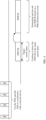
- FIG. 2 A diagram of a system architecture in the embodiments of this application is shown in FIG. 2 .
- a network device and user equipment (User Equipment, UE) 1 to UE 3 constitute a communications system.
- the UE 1 to the UE 3 may send uplink data to the network device, and the UE 1 to the UE 3 may also receive downlink data sent by the network device.
- UE User Equipment
- the embodiments of this application are mainly applied to the internet of things, the narrowband internet of things, or a new radio system.
- one NB-IoT carrier occupies 180 kHz in frequency domain, and corresponds to a width of 12 15-kHz subcarrier spacing in LTE.
- NB-IoT carriers are classified into an anchor (Anchor) NB-IoT carrier and a non-anchor (non-anchor) NB-IoT carrier.
- the anchor NB-IoT carrier is a carrier that carries at least one of a PSS, an SSS, or a physical broadcast channel (Physical Broadcast Channel, PBCH), and the non-anchor carrier does not carry a PSS, an SSS, or a PBCH.
- PBCH Physical Broadcast Channel
- a terminal device may camp on the anchor NB-IoT carrier.
- a non-anchor carrier may be configured on the anchor NB-IoT carrier by using system information block (System Information Block, SIB) information.
- SIB System Information Block
- the terminal device may complete paging (paging) based on the non-anchor carrier, and complete a random access procedure through a random access channel (RACH, Random access channel).
- the network device may alternatively configure a non-anchor carrier for the terminal device by using radio resource control (Radio Resource Control, RRC) signaling, and the terminal device and the network device may communicate with each other based on the non-anchor carrier.
- RRC Radio Resource Control
- an indication signal can implement the foregoing two functions is related to duration (Duration) of the indication signal, in addition to relating to whether a design of the indication signal can support the terminal device in using the indication signal to synchronize with the network device.
- Duration duration
- different NB-IoT carriers may have different transmit powers. Therefore, indication signals on different NB-IoT carriers have different coverage areas. For example, a transmitted indication signal with a 1-ms-subframe length can support only a terminal with a maximum coupling loss (Maximum coupling Loss, MCL) of 144 dB, while a terminal device with an MCL of 164 dB may be incapable of reliably detecting the indication signal.
- MCL maximum coupling Loss
- the duration of the indication signal is related to a coverage area of the indication signal. If the indication signal needs to meet a receiving requirement of a terminal device with worst cell coverage, comparatively long duration of the indication signal is required. If all terminal devices in a cell are enabled to be covered by the indication signal, duration of an indication channel may be excessively long. Consequently, comparatively high overheads of the indication signal may be caused, and scheduling of another service may be further affected. Based on this, the embodiments of this application provide an indication signal configuration method, to flexibly adjust a coverage area of an indication signal and control overheads of the indication signal.
- the indication signal is also referred to as a wakeup signal (Wakeup signal, WUS).
- WUS wakeup signal
- the indication signal may also refer to a power saving signal.
- all signals that are sent before an existing signal or channel and that are used by the terminal device to determine, based on the signals, whether to continue to receive signals associated with the signals or process channels associated with the signals may be referred to as the indication signal.
- the embodiments of this application are described by using a WUS as an example without loss of generality in this application.
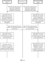
- FIG. 3a is a flowchart of an indication signal configuration method. The method includes the following steps.
- Step 300 A network device sends first configuration information and second configuration information.
- the first configuration information is used to indicate duration of a first indication signal corresponding to a first carrier.
- the second configuration information is used to indicate duration of a second indication signal corresponding to a second carrier.
- the first indication signal is used to indicate whether a first terminal device needs to continue to receive a signal or a channel associated with the first indication information.
- the second indication information is used to indicate whether a second terminal device needs to continue to receive a signal or a channel associated with the second indication information.
- the first terminal device is a terminal device that needs to receive the first indication signal.
- the second terminal device is a terminal device that needs to receive the second indication signal.
- the terminal device determines, based on an identifier of the terminal device and according to a preset rule, a carrier that needs to be processed or a working carrier, and further determines an indication signal that needs to be received. For example, the terminal device obtains a carrier ID through calculation based on a higher-layer user identifier and according to the preset rule that is agreed on with the network device, so that the terminal device determines to receive a paging message on a carrier corresponding to the carrier ID or send an uplink physical random access channel (Physical Random Access Channel, PRACH) on a carrier corresponding to the carrier ID.
- PRACH Physical Random Access Channel
- the network device sends the first configuration information and the second configuration information on an anchor carrier in a broadcasting manner.
- the duration of the first indication signal and the duration of the second indication signal are separately configured.
- the duration of the first indication signal is different from the duration of the second indication signal.
- the first carrier is an anchor carrier, and the second carrier is a non-anchor carrier; or the first carrier is a non-anchor carrier, and the second carrier is an anchor carrier.
- configurations of the duration of the first indication signal and the duration of the second indication signal may be determined based on target coverage areas of the indication signals and a power difference between the first carrier and the second carrier.
- the target coverage area is a coverage area corresponding to a maximum MCL that can meet target detection performance (including false alarm rate and miss detection rate performance) of the terminal device.
- the MCL is a measure of coverage.
- the first configuration information and the second configuration information may be carried in one message or two messages.
- the network device may add the first configuration information and the second configuration information to two messages and broadcast the two messages to the terminal device.
- the network device may add the first configuration information and the second configuration information to different configuration fields of one message, and broadcast the message to the terminal device.
- the network device may broadcast a plurality of pieces of configuration information, and each piece of configuration information indicates duration of an indication signal corresponding to a carrier.
- the duration that is of the first indication signal corresponding to the first carrier and that is indicated or configured by using the first configuration information means that the first terminal device can determine, only after detecting the indicated or configured duration of the first indication signal, that the network device does not send the first indication signal.
- the terminal device can determine that the first indication signal is not detected only after detecting a signal that is sent during a sufficiently long time (the configured duration) or performing joint detection on signals sent within the duration.
- the network device determines that the first terminal device is located within better coverage, when the network device needs to send a WUS signal, an actual time length for which the network device sends the WUS may be shorter than the duration that is of the first indication signal corresponding to the first carrier and that is configured and indicated by the first configuration information.
- Step 320a The first terminal device receives the first configuration information sent by the network device, and parses the first configuration information.
- the first terminal device can receive the first configuration information and the second configuration information that are sent by the network device.
- a carrier determined by the first terminal device based on an identifier of the first terminal device and according to a preset rule is the first carrier, and the first terminal device supports to receive or needs to receive the first indication signal. Further, the first terminal device determines that configuration information that needs to be parsed is the first configuration information.
- Step 320b The second terminal device receives the second configuration information sent by the network device, and parses the second configuration information.
- the second terminal device can receive the first configuration information and the second configuration information that are sent by the network device.
- a carrier determined by the second terminal device based on an identifier of the second terminal device and according to a preset rule is the second carrier, and the second terminal device supports to receive or needs to receive the second indication signal. Further, the second terminal device determines that configuration information that needs to be parsed is the second configuration information.
- Step 330 The network device sends the first indication signal on the first carrier, and sends the second indication signal on the second carrier.
- Step 340a The first terminal device receives the first indication signal on the first carrier.
- Step 340b The second terminal device receives the second indication signal on the second carrier.
- the network device configures duration of an indication signal corresponding to each carrier, so as to flexibly adjust, based on duration of an indication signal corresponding to each carrier configuration, a coverage area corresponding to the indication signal, and can effectively control overheads of the indication signal.
- Step 350a The first terminal device continues to receive the signal or the channel associated with the first indication information.
- the first indication signal instructs the first terminal device to continue to receive the signal or the channel associated with the first indication information.
- Step 350b The second terminal device skips continuing to receive the signal or the channel associated with the first indication information.
- the second indication signal instructs the second terminal device to skip continuing to receive the signal or the channel associated with the second indication information.
- FIG. 3b is a flowchart of an indication signal configuration method. The method includes the following steps.
- the method includes the following steps.
- Step 300' A network device sends first configuration information.
- the first configuration information is used to indicate duration of a first indication signal corresponding to a first carrier, and the first indication signal is used to indicate whether a first terminal device needs to continue to receive a signal or a channel associated with the first indication information.
- the first terminal device is a terminal device that needs to receive the first indication signal.
- the terminal device determines, based on an identifier of the terminal device and according to a preset rule, a carrier that needs to be processed or a working carrier, and further determines an indication signal that needs to be received. For example, the terminal device obtains a carrier ID through calculation based on a higher-layer user identifier and according to the preset rule that is agreed on with the network device, so that the terminal device determines to receive a paging message on a carrier corresponding to the carrier ID or send an uplink physical random access channel (Physical Random Access Channel, PRACH) on a carrier corresponding to the carrier ID.
- PRACH Physical Random Access Channel
- the network device sends the first configuration information on an anchor carrier in a broadcasting manner.
- the first carrier is an anchor carrier, or the first carrier is a non-anchor carrier.
- a configuration of the duration of the first indication signal may be determined based on a target coverage area of the indication signal and a power difference between the first carrier and the anchor carrier.
- the target coverage area is a coverage area corresponding to a maximum MCL that can meet target detection performance (including false alarm and miss detection performance) of the terminal device.
- the MCL is a measure of coverage.
- the network device may broadcast a plurality of pieces of configuration information, and each piece of configuration information indicates duration of an indication signal corresponding to a carrier. Without loss of generality, this application further protects a case in which only one carrier is configured.
- the duration that is of the first indication signal corresponding to the first carrier and that is indicated or configured by using the first configuration information means that the first terminal device can determine, only after detecting the indicated or configured duration of the first indication signal, that the based station does not send the first indication signal.
- the terminal device can determine that the first indication signal is not detected only after detecting a signal that is sent during a sufficiently long time (the configured duration) or performing joint detection on signals sent within the duration.
- the base station determines that the first terminal device is located within better coverage, when the base station needs to send a WUS signal, an actual time length for which the base station sends the WUS may be shorter than the duration that is of the first indication signal corresponding to the first carrier and that is configured and indicated by the first configuration information.
- Step 320a' The first terminal device receives the first configuration information sent by the network device, and parses the first configuration information.
- the first terminal device can receive the first configuration information sent by the network device.
- a carrier determined by the first terminal device based on an identifier of the first terminal device and according to a preset rule is the first carrier, and the first terminal device supports receiving or needs to receive the first indication signal. Further, the first terminal device determines that configuration information that needs to be parsed is the first configuration information.
- Step 330' The network device sends the first indication signal on the first carrier.
- Step 340a' The first terminal device receives the first indication signal on the first carrier.
- the network device can flexibly adjust, based on duration of an indication signal corresponding to each carrier configuration, a coverage area corresponding to the indication signal, and can effectively control overheads of the indication signal.
- Step 350a' The first terminal device continues to receive the signal or the channel associated with the first indication information.
- the first indication signal instructs the first terminal device to continue to receive the signal or the channel associated with the first indication information; or the terminal device skips continuing to receive the signal or the channel associated with the first indication information. In this case, the first indication signal instructs the first terminal device to skip continuing to receive the signal or the channel associated with the first indication information.
- the embodiments of this application further provide the following several types of configurations for the indication signal by the network device.
- the following uses an example in which only the first terminal device receives an indication signal for description.
- Another terminal device has a same processing process.
- the following configuration does not depend on the embodiment shown in FIG. 2 , and may be used independently.
- the first configuration information further indicates a first determining threshold, and the first determining threshold is used to instruct the first terminal device to determine whether to receive the first indication signal on the first carrier.
- the first terminal device determines that a measurement value of a preset parameter is less than the first determining threshold corresponding to the first carrier, the first terminal device does not receive the first indication signal on the first carrier; or if the first terminal device determines that a measurement value of a preset parameter is greater than or equal to the first determining threshold corresponding to the first carrier, the first terminal device receives the first indication signal on the first carrier.
- receiving the first indication signal on the first carrier means that the terminal device receives the first indication signal, and determines, based on an indication of the first indication signal, whether to continue to receive the signal associated with the first indication signal or process the channel associated with the first indication signal. If the first indication signal instructs the terminal device to continue to receive the signal associated with the first indication signal or process the channel associated with the first indication signal, the terminal device continues to receive the signal associated with the first indication signal or process the channel associated with the first indication signal; or if the first indication signal instructs the terminal device to skip continuing to receive the signal associated with the first indication signal or process the channel associated with the first indication signal, the terminal device does not receive the signal associated with the first indication signal or process the channel associated with the first indication signal.
- the terminal device may turn off a receiver to reduce power consumption. Not receiving the first indication signal on the first carrier means that the terminal device does not use the first indication signal, but directly receives the signal associated with the first indication signal or processes the channel associated with the first indication signal.
- the first terminal device when the measurement value of the preset parameter is less than the first determining threshold corresponding to the first carrier, the first terminal device is located outside the target coverage area of the first indication signal, for example, the first terminal device is located in a cell edge area or a poor coverage area. If the first terminal device still determines, by receiving the indication signal, whether the first terminal device needs to continue to receive the signal associated with the indication information or process the channel associated with the indication signal, due to missing detection of the indication signal, there is a high probability that the first terminal device does not receive the associated signal that needs to be received or does not process the associated channel that needs to be processed. This causes data loss, and affects communication between the first terminal device and the network device.
- first determining threshold herein is configured for the first carrier, and the network device may configure different determining thresholds for different carriers.
- second configuration information further indicates a second determining threshold, and the second determining threshold is used to instruct a second terminal device to determine whether to receive a second indication signal on a second carrier.
- the network device may uniformly configure a same determining threshold for different carriers. For details, refer to Manner 4 in the following.
- the first configuration information further indicates a third determining threshold.
- the third determining threshold corresponding to the first carrier is used to instruct the first terminal device to determine, in case of receiving the first indication signal on the first carrier, whether to use a synchronization signal to synchronize with the network device.
- the first terminal device determines that a measurement value of a preset parameter is less than the third determining threshold, the first terminal device first uses the synchronization signal to synchronize with the network device, and then receives the first indication signal on the first carrier.
- the first terminal device determines that a measurement value of a preset parameter is less than the third determining threshold, the first terminal device does not use the synchronization signal to perform synchronization before receiving the first indication signal on the first carrier, but after receiving the first indication signal before receiving the signal associated with the first indication signal or processing the channel associated with the first indication signal, uses the synchronization signal to synchronize with the network device; or if the first terminal device determines that a measurement value of a preset parameter is greater than or equal to the third determining threshold, the first terminal device receives the first indication signal on the first carrier, and uses the first indication signal to synchronize with the network device.
- the first terminal device when the measurement value of the preset parameter is less than the third determining threshold, if the first terminal device still uses the indication signal to synchronize with the network device, this may cause a synchronization failure, and affect communication between the first terminal device and the network device. Therefore, the first terminal device needs to use the synchronization signal (for example, a PSS and an SSS) to synchronize with the network device.
- the synchronization signal for example, a PSS and an SSS
- the third determining threshold herein is configured for the first carrier, and the network device may configure different determining thresholds for different carriers.
- second configuration information further indicates a fourth determining threshold, and the fourth determining threshold is used to instruct the second terminal device to determine, in case of receiving the second indication signal on the second carrier, whether to use the synchronization signal to synchronize with the network device.
- the network device may uniformly configure a same determining threshold for different carriers. For details, refer to Manner 5 in the following.
- the first configuration information further indicates a fifth determining threshold and a sixth determining threshold.
- the fifth determining threshold is less than the sixth determining threshold.
- the fifth determining threshold and the sixth determining threshold are used to instruct the first terminal device to determine whether to receive the first indication signal on the first carrier, and determine, in case of receiving the first indication signal on the first carrier, whether to use a synchronization signal to synchronize with the network device.
- the first terminal device determines that a measurement value of a preset parameter is less than the fifth determining threshold, the first terminal device does not receive the first indication signal on the first carrier.
- the first terminal device determines that a measurement value of a preset parameter is greater than or equal to the fifth determining threshold and less than the sixth determining threshold, the first terminal device first uses the synchronization signal to synchronize with the network device, and then receives the first indication signal on the first carrier; or if the first terminal device determines that a measurement value of a preset parameter is greater than or equal to the fifth determining threshold and less than the sixth determining threshold, after receiving the first indication signal on the first carrier, the first terminal device uses the synchronization signal to synchronize with the network device.
- the first terminal device determines that a measurement value of a preset parameter is greater than or equal to the sixth determining threshold, the first terminal device receives the first indication signal on the first carrier, and uses the first indication signal to synchronize with the network device.
- Manner 3 may be considered as a combination of Manner 1 and Manner 2. For details, refer to the specific descriptions of Manner 1 and Manner 2. Repeated parts are not described again.
- the fifth determining threshold and the sixth determining threshold herein are configured for the first carrier, and the network device may configure different determining thresholds for different carriers.
- second configuration information further indicates a seventh determining threshold and an eighth determining threshold.
- the seventh determining threshold is less than the eighth determining threshold.
- the seventh determining threshold and the eighth determining threshold are used to instruct the second terminal device to determine whether to receive the second indication signal on the second carrier, and determine, in case of receiving the second indication signal on the second carrier, whether to use the synchronization signal to synchronize with the network device.
- the network device may uniformly configure a same determining threshold for different carriers. For details, refer to Manner 6 in the following.
- the fifth determining threshold may be equal to or unequal to the first determining threshold in Manner 1
- the sixth determining threshold may be equal to or unequal to the third determining threshold in Manner 2.
- the first terminal device can accurately determine, based on the measurement value of the preset parameter, the fifth determining threshold, and the sixth determining threshold, a case in which an indication signal is not received, a case in which an indication signal is received but the indication signal is not used to synchronize with the network device, and a case in which an indication signal is received and the indication signal is used to synchronize with the network device. Therefore, in Manner 3, it can be better ensured that the first terminal device and the network device normally communicate with each other, and ensured that the terminal device always selects a low-power-consumption manner to communicate with the network device.
- determining thresholds in Manner 1 to Manner 3 are all based on a carrier configuration, that is, the network device needs to configure a corresponding determining threshold for each carrier. Alternatively, the network device may uniformly configure a same determining threshold for different carriers. A difference between Manner 4 to Manner 6 and Manner 1 to Manner 3 lies in that the network device configures only one determining threshold if determining thresholds have a same function.
- Manner 4 The network device sends third configuration information, where the third configuration information indicates a ninth determining threshold.
- the ninth determining threshold is used to instruct the terminal device that needs to receive the first indication signal to determine whether to receive the first indication signal on the first carrier, and is used to instruct the second terminal device to determine whether to receive the second indication signal on the second carrier.
- the first carrier and the second carrier herein are merely examples, and other carriers configured in the cell may be further included. Therefore, regardless of which carrier is determined by the first terminal device, the ninth determining threshold may be used to determine whether the corresponding indication signal is received on the determined carrier.
- a carrier determined by a terminal device A is the first carrier, and the terminal device A determines that a measurement value of a preset parameter is greater than or equal to the ninth determining threshold, the terminal device A receives the first indication signal on the first carrier; or if the terminal device A determines that a measurement value of a preset parameter is less than the ninth determining threshold, the terminal device A does not receive the first indication signal on the first carrier.
- the terminal device A receives the second indication signal on the second carrier; or if the terminal device A determines that a measurement value of a preset parameter is less than the ninth determining threshold, the terminal device A does not receive the second indication signal on the second carrier.
- a function of the ninth determining threshold herein is the same as a function of the first determining threshold in Manner 1.
- the network device does not need to separately configure a determining threshold for each carrier, and all carriers share one determining threshold, that is, the ninth determining threshold.
- Manner 5 The network device sends fourth configuration information, where the fourth configuration information indicates a tenth determining threshold.
- the tenth determining threshold is used to instruct the first terminal device to determine, in case of receiving the first indication signal on the first carrier, whether to use a synchronization signal to synchronize with the network device; and is used to instruct the second terminal device to determine, in case of receiving the second indication signal on the second carrier, whether to use the synchronization signal to synchronize with the network device.
- the first terminal device determines that a measurement value of a preset parameter is less than the tenth determining threshold, the first terminal device first uses the synchronization signal to synchronize with the network device, and then receives the first indication signal on the first carrier. Alternatively, if the first terminal device determines that a measurement value of a preset parameter is less than the tenth determining threshold, after receiving the first indication signal on the first carrier, the first terminal device uses the synchronization signal to synchronize with the network device.
- the first terminal device determines that a measurement value of a preset parameter is greater than or equal to the tenth determining threshold, the first terminal device receives the first indication signal on the first carrier, and uses the first indication signal to synchronize with the network device.
- a function of the tenth determining threshold herein is the same as a function of the third determining threshold in Manner 2. According to the method provided in Manner 5, the network device does not need to separately configure a determining threshold for each carrier, and all carriers share one determining threshold, that is, the tenth determining threshold.
- Manner 6 The network device sends fifth configuration information, where the fifth configuration information indicates an eleventh determining threshold and a twelfth determining threshold.
- the eleventh determining threshold and the twelfth determining threshold are used to instruct the first terminal device to determine whether to receive the first indication signal on the first carrier, and determine, in case of receiving the first indication signal on the first carrier, whether to use a synchronization signal to synchronize with the network device; and are used to instruct the second terminal device to determine whether to receive the second indication signal on the second carrier, and determine, in case of receiving the second indication signal on the second carrier, whether to use the synchronization signal to synchronize with the network device.
- the eleventh determining threshold is less than the twelfth determining threshold.
- a carrier determined by the first terminal device is the first carrier. If the first terminal device determines that a measurement value of a preset parameter is less than the eleventh determining threshold, the first terminal device does not receive the first indication signal on the first carrier.
- the first terminal device determines that a measurement value of a preset parameter is greater than or equal to the eleventh determining threshold and less than the twelfth determining threshold, the first terminal device first uses the synchronization signal to synchronize with the network device, and then receives the first indication signal on the first carrier; or if the first terminal device determines that a measurement value of a preset parameter is greater than or equal to the eleventh determining threshold and less than the twelfth determining threshold, after receiving the first indication signal on the first carrier, the first terminal device uses the synchronization signal to synchronize with the network device.
- the first terminal device determines that a measurement value of a preset parameter is greater than or equal to the twelfth determining threshold, the first terminal device receives the first indication signal on the first carrier, and uses the first indication signal to synchronize with the network device.
- the measurement value of the preset parameter in Manner 1 to Manner 6 may be an RSRP value obtained by the terminal device through measurement based on an NPSSS and an NSSS that are sent on an anchor carrier.
- the first terminal device when the RSRP value is greater than the first determining threshold, the first terminal device receives the first indication signal on the first carrier, and determines, by using the first indication signal, whether the signal associated with the first indication signal needs to be received or the channel associated with the first indication signal needs to be processed; or when the RSRP value is less than the first determining threshold, the first terminal device does not receive the first indication signal, but directly receives the signal associated with the first indication signal or processes the channel associated with the first indication signal.
- the first terminal device when the RSRP value is greater than the ninth determining threshold, the first terminal device receives the first indication signal on the first carrier, and determines, by using the first indication signal, whether the signal associated with the first indication signal needs to be received or the channel associated with the first indication signal needs to be processed; or when the RSRP value is less than the ninth determining threshold, the first terminal device does not receive the first indication signal, but directly receives the signal associated with the first indication signal or processes the channel associated with the first indication signal.
- the first terminal device when the RSRP value is greater than the third determining threshold, it indicates that the first terminal device receives the first indication signal on the first carrier, and uses the first indication signal to directly perform synchronization; or when the RSRP value is less than the third determining threshold, the first terminal device does not use the first indication signal to perform synchronization, but uses the synchronization signal to perform synchronization before or after receiving the first indication signal.
- the first terminal device when the RSRP value is less than the fifth determining threshold, the first terminal device does not receive the first indication signal, but directly receives the signal associated with the first indication signal or processes the channel associated with the first indication signal; when the RSRP value is greater than the fifth determining threshold and less than the sixth determining threshold, the first terminal device does not use the first indication signal to perform synchronization, but uses the synchronization signal to perform synchronization before or after receiving the first indication signal; or when the RSRP value is greater than the sixth determining threshold, the first terminal device receives the first indication signal on the first carrier, and uses the first indication signal to directly perform synchronization.
- the first terminal device when the RSRP value is less than the eleventh determining threshold, the first terminal device does not receive the first indication signal, but directly receives the signal associated with the first indication signal or processes the channel associated with the first indication signal; when the RSRP value is greater than the eleventh determining threshold and less than the twelfth determining threshold, the first terminal device does not use the first indication signal to perform synchronization, but uses the synchronization signal to perform synchronization before or after receiving the first indication signal; or when the RSRP value is greater than the twelfth determining threshold, the first terminal device receives the first indication signal on the first carrier, and uses the first indication signal to directly perform synchronization.
- the measurement value of the preset parameter may be alternatively a measurement value of another parameter, and a determining condition may accordingly change.
- the preset parameter is a quantity of subframes required by the terminal device to receive a paging message
- a smaller quantity of subframes indicates better signal coverage in an area in which the terminal device is located, and indicates better signal quality of an indication signal received by the terminal device.
- the preset parameter is a transmission time length required by the terminal device to achieve WUS detection performance
- a shorter required transmission time length indicates better signal coverage of an area in which the terminal device is located, and indicates better signal quality of an indication signal received by the terminal device.
- the threshold is a WUS sending time length configured by the network.
- the determining condition correspondingly changes to: If the first terminal device determines that the measurement value of the preset parameter is greater than the first determining threshold, the first terminal device does not receive the first indication signal on the first carrier; or if the first terminal device determines that the measurement value of the preset parameter is less than or equal to the first determining threshold, the first terminal device receives the first indication signal on the first carrier.
- the determining condition correspondingly changes to: If the first terminal device determines that the measurement value of the preset parameter is greater than or equal to the third determining threshold, the first terminal device first uses the synchronization signal to synchronize with the network device, and then receives the first indication signal on the first carrier; or if the first terminal device determines that the measurement value of the preset parameter is greater than or equal to the third determining threshold, the first terminal device does not use the synchronization signal to perform synchronization before receiving the first indication signal on the first carrier, but after receiving the first indication signal before receiving the signal associated with the first indication signal or processing the channel associated with the first indication signal, uses the synchronization signal to synchronize with the network device; or if the first terminal device determines that the measurement value of the preset parameter is less than the third determining threshold, the first terminal device receives the first indication signal on the first carrier, and uses the first indication signal to synchronize with the network device.
- the first terminal device determines that the measurement value of the preset parameter is greater than or equal to the sixth determining threshold, the first terminal device does not receive the first indication signal on the first carrier.
- the first terminal device determines that the measurement value of the preset parameter is greater than or equal to the fifth determining threshold and less than the sixth determining threshold, the first terminal device first uses the synchronization signal to synchronize with the network device, and then receives the first indication signal on the first carrier; or if the first terminal device determines that the measurement value of the preset parameter is greater than or equal to the fifth determining threshold and less than the sixth determining threshold, after receiving the first indication signal on the first carrier, the first terminal device uses the synchronization signal to synchronize with the network device.
- the first terminal device determines that the measurement value of the preset parameter is less than the fifth determining threshold, the first terminal device receives the first indication signal on the first carrier, and uses the first indication signal to synchronize with the network device.
- the network device may configure different measurement values of preset parameters and corresponding first determining thresholds based on a relationship between a measurement value of a preset parameter and signal coverage of an area in which the first terminal device is located; and based on a configuration of the network device, the first terminal device determines, based on an indication of the first indication signal, whether to receive the signal associated with the first indication signal or process the channel associated with the first indication signal.
- the first terminal device when signal receiving quality corresponding to the measurement value, obtained through measurement by the first terminal device, of the preset parameter is lower than signal receiving quality corresponding to the first determining threshold, the first terminal device does not receive the first indication signal on the first carrier, and does not use the first indication signal to determine whether to receive the signal associated with the first indication signal or process the channel associated with the first indication signal; or when signal receiving quality corresponding to the measurement value, obtained through measurement by the first terminal device, of the preset parameter is higher than or the same as signal receiving quality corresponding to the first determining threshold, the first terminal device receives the first indication signal on the first carrier, and uses the first indication signal to determine whether to receive the signal associated with the first indication signal or process the channel associated with the first indication signal.
- the first terminal device when signal receiving quality corresponding to the measurement value, obtained through measurement by the first terminal device, of the preset parameter is lower than signal receiving quality corresponding to the third determining threshold, the first terminal device does not use the first indication signal to perform synchronization; or when signal receiving quality corresponding to the measurement value, obtained through measurement by the first terminal device, of the preset parameter is higher than or the same as signal receiving quality corresponding to the third determining threshold, the first terminal device uses the first indication signal to perform synchronization.
- a function of the eleventh determining threshold herein is the same as a function of the fifth determining threshold in Manner 3
- a function of the twelfth determining threshold is the same as a function of the sixth determining threshold in Manner 3.
- the network device does not need to separately configure two determining thresholds for each carrier, and all carriers share the eleventh determining threshold and the twelfth determining threshold.
- the determining thresholds mentioned in Manner 1 to Manner 6 are all set for a reference signal received power (Reference Signal Received Power, RSRP).
- the first terminal device receives a reference signal on an anchor carrier, and determines an RSRP corresponding to the reference signal as the measurement value of the preset parameter.
- the anchor carrier herein may be the first carrier, the second carrier, or another carrier.
- the measurement value of the preset parameter may be alternatively another parameter, and the determining condition may accordingly change.
- the preset parameter is a quantity of subframes required by the terminal device to receive a paging message
- a smaller quantity of subframes indicates better coverage for the terminal device.
- the determining condition in this solution of this application is correspondingly adjusted.
- the measurement value of the preset parameter is a WUS sending time length required when the terminal device detects that a WUS meets preset detection performance
- a configured threshold is a WUS sending time length configured by the network.
- a smaller measurement value of the preset parameter indicates better coverage for the terminal device.
- the determining condition in this solution of this application is correspondingly adjusted.
- the first terminal device determines whether to use the first indication information to perform synchronization.
- the first terminal device does not receive the first indication signal on the first carrier, and does not use the first indication signal to determine whether to process a subsequent associated channel or signal; or when terminal coverage corresponding to the measurement value of the preset parameter is better than or the same as terminal coverage corresponding to the determining threshold, the first terminal device receives the first indication signal on the first carrier, and determines, by using the first indication signal, whether to process a subsequent associated channel or signal.
- the first terminal device uses the first indication signal to perform synchronization.
- the network device configures an idle mode discontinuous reception cycle (IDLE mode Discontinuous Reception, IDLE mode DRX cycle, referred to as DRX cycle below), and the terminal device wakes up at time locations of these DRX cycles used as cycles.
- the time location is referred to as a paging occasion (Paging Occasion, PO).
- the terminal device detects a common search space (common Search Space) starting from a PO.
- the terminal device detects a PDCCH scheduled to the terminal device, that is, DCI carried on the PDCCH is scrambled by using a paging-radio network temporary identifier (Paging-Radio Network Temporary Identity, P-RNTI), the terminal device demodulates and decodes a paging message (Paging message) carried on a PDSCH scheduled by using the DCI.
- P-RNTI paging-Radio Network Temporary Identity
- the terminal device synchronizes with the network device by using a PSS or an SSS. Therefore, after an indication signal (for example, a WUS) is introduced, the terminal device may not need to use the PSS and the SSS to synchronize with the network device, but use the indication signal to synchronize with the network device, thereby further reducing power consumption of the terminal device.
- an indication signal for example, a WUS
- the terminal device may read the WUS in the following three manners.
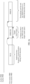
- Procedure (procedure) 1 This procedure is used to determine whether the terminal device needs to further receive subsequent paging, that is, determine whether to detect the PDCCH in the common search space starting from the PO, but the terminal device needs to synchronize with the network device first.
- the terminal device before receiving the WUS, the terminal device first synchronizes with the network device by using the PSS and the SSS. After completing the synchronization, the terminal device receives the WUS. If indication information carried in the WUS instructs the terminal device to continue to process a subsequent associated PDCCH and PDSCH, the terminal device continues to detect the PDCCH in the common search space starting from the PO, as shown in FIG. 5a . If indication information carried in the received WUS instructs the terminal device not to process a subsequent associated PDCCH and PDSCH, the terminal device does not need to continue to detect the PDCCH in the common search space starting from the PO, as shown in FIG. 5b .
- the WUS may carry, in the following manner, the indication information to indicate whether the terminal device continues to process the subsequent associated channel or signal: When a preset WUS signal is sent, it indicates that the terminal device is instructed to continue to process the subsequent associated channel or signal; or when no preset WUS signal is sent (in this case, the network device may send another signal or scheduling data, which is generally denoted as sending DTX), it indicates that the terminal device is instructed to skip continuing to process the subsequent associated channel or signal.
- the WUS may carry, in the following manner, the indication information to indicate whether the terminal device continues to process the subsequent associated channel or signal: When a preset WUS signal 1 is sent, it indicates that the terminal device is instructed to continue to process the subsequent associated channel or signal; or when a preset WUS signal 2 is sent, it indicates that the terminal device is instructed to skip continuing to process the subsequent associated channel or signal.
- the foregoing are two examples in which the indication information carried in the WUS indicates whether the terminal device continues to process the subsequent associated channel or signal. This application is not limited to the foregoing two manners.
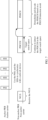
- Procedure 2 This procedure is used to determine whether the terminal device needs to further receive subsequent paging, that is, determine whether to detect the PDCCH in the common search space starting from the PO, and the terminal device may use a WUS to implement time-frequency synchronization with the network device, and directly detect the PDCCH in the common search space starting from the PO.
- the terminal device receives the WUS. If the terminal device receives the WUS, and the terminal device simultaneously implements time-frequency synchronization with the network device, the terminal device directly continues to detect the PDCCH in the common search space starting from the PO, as shown in FIG. 6a ; or if the terminal device receives no WUS, the terminal device does not need to continue to detect the PDCCH in the common search space starting from the PO, as shown in FIG. 6b .
- Procedure 3 This procedure is used to determine whether the terminal device needs to further receive subsequent paging, that is, determine whether to detect the PDCCH in the common search space starting from the PO. However, after receiving a WUS, the terminal device needs to first synchronize with the network device, and then the terminal device detects the PDCCH in the common search space starting from the PO.
- the terminal device receives the WUS. If the terminal device receives the WUS, the terminal device first needs to synchronize with the network device, and then detects the PDCCH in the common search space starting from the PO, as shown in FIG. 7 ; or if the terminal device receives no WUS, the terminal device does not need to synchronize with the network device, and the terminal device does not need to continue to detect PDCCH in the common search space starting from the PO either, as shown in FIG. 6b .
- UE User Equipment
- the UE determines that a measured RSRP 1 ⁇ A, the UE directly detects the PDCCH in the common search space starting from the PO, and does not receive or process the WUS.
- the UE determines that a measured RSRP 1 ⁇ A, when the UE receives the WUS or indication information carried in the WUS instructs the UE to continue to process the subsequent associated PDCCH and PDSCH, the UE detects the PDCCH in the common search space starting from the PO; or if the UE receives no WUS or indication information carried in the WUS instructs the UE to skip continuing to process the subsequent associated PDCCH and PDSCH, the UE does not detect the PDCCH in the common search space starting from the PO.
- the UE determines that a measured RSRP 1 ⁇ B, the UE performs the foregoing procedure 1. To be specific, before receiving the WUS, the UE first synchronizes with the network device. If receiving the WUS, the UE continues to detect the PDCCH in the common search space starting from the PO. If receiving no WUS, the UE does not detect the PDCCH in the common search space starting from the PO. Alternatively, the UE performs the foregoing procedure 3. If receiving the WUS, the UE synchronizes with the network device after receiving the WUS, and continues to detect the PDCCH in the common search space starting from the PO. If receiving no WUS, the UE does not detect the PDCCH in the common search space starting from the PO.
- the UE determines that a measured RSRP 1 ⁇ B, the UE performs the foregoing procedure 2.
- the UE receives the WUS or indication information carried in the WUS instructs the UE to continue to process the subsequent associated PDCCH and PDSCH, and the UE may simultaneously implement time-frequency synchronization with the network device, the UE continues to detect the PDCCH in the common search space starting from the PO; or if the UE receives no WUS or indication information carried in the WUS instructs the UE to skip continuing to process the subsequent associated PDCCH and PDSCH, the UE does not detect the PDCCH in the common search space starting from the PO.
- the UE determines that a measured RSRP 1 ⁇ A, the UE directly detects the PDCCH in the common search space starting from the PO, and does not receive the WUS.
- the UE determines that A ⁇ RSRP 1 ⁇ B, the UE performs the foregoing procedure 1. To be specific, before receiving the WUS, the UE first synchronizes with the network device. If receiving the WUS, the UE continues to detect the PDCCH in the common search space starting from the PO. If receiving no WUS, the UE does not detect the PDCCH in the common search space starting from the PO. Alternatively, the UE performs the foregoing procedure 3. If receiving the WUS, the UE synchronizes with the network device after receiving the WUS, and continues to detect the PDCCH in the common search space starting from the PO. If receiving no WUS, the UE does not detect the PDCCH in the common search space starting from the PO.
- the UE determines that a measured RSRP 1 ⁇ B, the UE performs the foregoing procedure 2.
- the UE receives the WUS and the UE may also implement time-frequency synchronization with the network device, the UE continues to detect the PDCCH in the common search space starting from the PO; or if the UE receives no WUS, the UE does not detect the PDCCH in the common search space starting from the PO.
- the network elements include corresponding hardware structures and/or software modules for performing the foregoing functions.
- a person skilled in the art should be easily aware that, units and algorithm steps in the examples described with reference to the embodiments disclosed in this application may be implemented by hardware or a combination of hardware and computer software. Whether a function is performed by hardware or hardware driven by computer software depends on particular applications and design constraints of the technical solutions. A person skilled in the art may use different methods to implement the described functions for each particular application, but it should not be considered that the implementation goes beyond the scope of this application.
- FIG. 8 is a schematic diagram of a communications apparatus according to this application.
- the communications apparatus may be a network device, or may be a chip or a system-on-a-chip in a network device, and may perform the method performed by the network device in the embodiment shown in FIG. 3 .
- the communications apparatus 800 includes at least one processor 810 and a memory 830.
- the memory 830 is configured to store a program, and may be a ROM, another type of static storage device that can store static information and an instruction, for example, a RAM, or another type of dynamic storage device that can store information and an instruction, or may be an electrically erasable programmable read-only memory (Electrically erasable programmable-only memory, EEPROM), a compact disc read-only memory (compact disc read-only memory, CD-ROM) or another optical disc storage, an optical disc storage (including a compressed optical disc, a laser disc, an optical disc, a digital versatile optical disc, a Blu-ray disc, or the like), a disk storage medium or another magnetic storage device, or any other medium that can carry or store an expected program in a form of an instruction or a data structure and that can be accessed by a computer, but is not limited thereto.
- the memory 830 may exist independently, and is connected to the processor 810.
- the memory 830 may be alternatively integrated with the processor 810.
- the processor 810 is configured to execute the program in the memory 830, to implement the steps performed by the network device in the indication signal configuration method in the embodiments of this application. For related features, refer to the foregoing descriptions. Details are not described herein again.
- the processor 810 may be a general-purpose CPU, a microprocessor, a specific ASIC, or one or more integrated circuits configured to control program execution of the solutions of this application.
- the processor 810 may include one or more CPUs, for example, a CPU 0 and a CPU 1 in FIG. 8 .
- the apparatus 800 may include a plurality of processors, for example, the processor 810 and a processor 811 in FIG. 8 .
- Each of the processors may be a single-core (single-CPU) processor, or may be a multi-core (multi-CPU) processor.
- the processor may be one or more devices, circuits, and/or processing cores for processing data (for example, a computer program instruction).
- the communications apparatus 800 may further include a transceiver 820 shown in FIG. 8 , where the transceiver 820 is configured to communicate with another device or a communications network.
- the transceiver 820 includes a radio frequency circuit.
- the processor 810, the transceiver 820, and the memory 830 may be connected by using a communications bus.
- the communications bus may include a path for transmitting information between the foregoing units.
- the processor 810 may send or receive data by using an input/output interface, a pin, a circuit, or the like.
- FIG. 9 is a schematic diagram of another communications apparatus according to an embodiment of this application.
- the apparatus may be a network device, or may be a chip or a system-on-a-chip in a network device, and may perform the method performed by the network device in the embodiment shown in FIG. 3 .
- the apparatus includes a processing unit 901 and a communications unit 902.
- the communications unit 902 is configured to: send first configuration information and second configuration information, send a first indication signal on a first carrier, and send a second indication signal on a second carrier, where the first configuration information is used to indicate duration of the first indication signal corresponding to the first carrier, the second configuration information is used to indicate duration of the second indication signal corresponding to the second carrier, the first indication signal is used to indicate whether a first terminal device continues to receive a signal associated with the first indication signal or process a channel associated with the first indication signal, the second indication information is used to indicate whether a second terminal device continues to receive a signal associated with the second indication signal or process a channel associated with the second indication signal, the first terminal device is a terminal device that needs to receive the first indication signal, and the second terminal device is a terminal device that needs to receive the second indication signal.
- the first configuration information and the second configuration information are generated by the processing unit 901.
- the duration of the first indication signal is different from the duration of the second indication signal.
- the first carrier is an anchor carrier
- the second carrier is a non-anchor carrier
- the first configuration information further indicates a first determining threshold, and the first determining threshold is used to instruct the first terminal device to determine whether to receive the first indication signal on the first carrier; and the second configuration information further indicates a second determining threshold, and the second determining threshold is used to instruct the second terminal device to determine whether to receive the second indication signal on the second carrier.
- the first configuration information further indicates a third determining threshold
- the second configuration information further indicates a fourth determining threshold.
- the third determining threshold is used to instruct the first terminal device to determine, in case of receiving the first indication signal on the first carrier, whether to use a synchronization signal to synchronize with the network device.
- the fourth determining threshold is used to instruct the second terminal device to determine, in case of receiving the second indication signal on the second carrier, whether to use the synchronization signal to synchronize with the network device.
- the first configuration information further indicates a fifth determining threshold and a sixth determining threshold, and the fifth determining threshold is less than the sixth determining threshold.
- the second configuration information further indicates a seventh determining threshold and an eighth determining threshold, and the seventh determining threshold is less than the eighth determining threshold.
- the fifth determining threshold and the sixth determining threshold are used to instruct the first terminal device to determine whether to receive the first indication signal on the first carrier, and determine, in case of receiving the first indication signal on the first carrier, whether to use a synchronization signal to synchronize with the network device.
- the seventh determining threshold and the eighth determining threshold are used to instruct the second terminal device to determine whether to receive the second indication signal on the second carrier, and determine, in case of receiving the second indication signal on the second carrier, whether to use the synchronization signal to synchronize with the network device.
- the communications unit 902 is further configured to send third configuration information, where the third configuration information indicates a ninth determining threshold.
- the ninth determining threshold is used to instruct the first terminal device to determine whether to receive the first indication signal on the first carrier, and is used to instruct the second terminal device to determine whether to receive the second indication signal on the second carrier.
- the communications unit 902 is further configured to send fourth configuration information, where the fourth configuration information indicates a tenth determining threshold.
- the tenth determining threshold is used to instruct the first terminal device to determine, in case of receiving the first indication signal on the first carrier, whether to use a synchronization signal to synchronize with the network device; and is used to instruct the second terminal device to determine, in case of receiving the second indication signal on the second carrier, whether to use the synchronization signal to synchronize with the network device.
- the communications unit 902 is further configured to send fifth configuration information, where the fifth configuration information indicates an eleventh determining threshold and a twelfth determining threshold, and the eleventh determining threshold is less than the twelfth determining threshold.
- the eleventh determining threshold and the twelfth determining threshold are used to instruct the first terminal device to determine whether to receive the first indication signal on the first carrier, and determine, in case of receiving the first indication signal on the first carrier, whether to use a synchronization signal to synchronize with the network device; and are used to instruct the second terminal device to determine whether to receive the second indication signal on the second carrier, and determine, in case of receiving the second indication signal on the second carrier, whether to use the synchronization signal to synchronize with the network device.
- the communications apparatus may be configured to implement steps performed by the network device in the indication signal configuration method in the embodiments of this application.
- steps performed by the network device in the indication signal configuration method in the embodiments of this application.
- FIG. 10 is a schematic diagram of a communications apparatus according to this application.
- the communications apparatus may be, for example, a terminal device or a chip or a system-on-a-chip in a terminal device, and may perform the method performed by the terminal device in the embodiment shown in FIG. 3 .
- the communications apparatus 1000 includes at least one processor 1010 and a memory 1030.
- the memory 1030 is configured to store a program, and may be a ROM, another type of static storage device that can store static information and an instruction, for example, a RAM, or another type of dynamic storage device that can store information and an instruction, or may be an EEPROM, a CD-ROM or another optical disc storage, an optical disc storage (including a compressed optical disc, a laser disc, an optical disc, a digital versatile optical disc, a Blu-ray disc, or the like), a disk storage medium or another magnetic storage device, or any other medium that can carry or store an expected program in a form of an instruction or a data structure and that can be accessed by a computer, but is not limited thereto.
- the memory 1030 may exist independently, and is connected to the processor 1010.
- the memory 1030 may be alternatively integrated with the processor 1010.
- the processor 1010 is configured to execute the program in the memory 1030, to implement the steps performed by the terminal device in the indication signal configuration method in the embodiments of this application. For related features, refer to the foregoing descriptions. Details are not described herein again.
- the processor 1010 may be a general-purpose CPU, a microprocessor, a specific ASIC, or one or more integrated circuits configured to control program execution of the solutions of this application.
- the processor 1010 may include one or more CPUs, for example, a CPU 0 and a CPU 1 in FIG. 10 .
- the apparatus 1000 may include a plurality of processors, for example, the processor 1010 and a processor 1011 in FIG. 10 .
- Each of the processors may be a single-core (single-CPU) processor, or may be a multi-core (multi-CPU) processor.
- the processor may be one or more devices, circuits, and/or processing cores for processing data (for example, a computer program instruction).
- the communications apparatus 1000 may further include a transceiver 1020 shown in FIG. 10 , where the transceiver 1020 is configured to communicate with another device or a communications network.
- the transceiver 1020 includes a radio frequency circuit.
- the processor 1010, the transceiver 1020, and the memory 1030 may be connected by using a communications bus.
- the communications bus may include a path for transmitting information between the foregoing units.
- the processor 1010 may send or receive data by using an input/output interface, a pin, a circuit, or the like.
- FIG. 11 is a schematic diagram of another communications apparatus according to an embodiment of this application.
- the communications apparatus may be a terminal device, or may be a chip or a system-on-a-chip in a terminal device, and may perform the method performed by the first terminal device in the embodiment shown in FIG. 3 .
- the communications apparatus includes a processing unit 1101 and a communications unit 1102.
- the communications unit 1102 is configured to: receive first configuration information sent by a network device, and receive a first indication signal on a first carrier. Then, the communications unit 1102 is further configured to continue to receive a signal associated with the first indication signal or process a channel associated with the first indication signal, or skip continuing to receive a signal associated with the first indication signal or process a channel associated with the first indication signal.
- the first configuration information is used to indicate duration of the first indication signal sent on the first carrier.
- the duration of the first indication signal is independent of duration of a second indication signal received by a second terminal device on a second carrier.
- the first indication signal is used to indicate whether a first terminal device continues to receive the signal associated with the first indication signal or process the channel associated with the first indication signal.
- the second indication information is used to indicate whether the second terminal device continues to receive a signal associated with the second indication signal or process a channel associated with the second indication signal.
- the processing unit 1101 is configured to trigger the communications unit 1102.
- the duration of the first indication signal is different from the duration of the second indication signal.
- the first configuration information further indicates a first determining threshold.
- the processing unit 1101 is configured to determine that a measurement value of a preset parameter is greater than or equal to a first determining threshold, and the first terminal device receives the first indication signal on the first carrier.
- the first configuration information further indicates a third determining threshold. If the processing unit 1101 determines that a measurement value of a preset parameter is less than the third determining threshold, the communications unit 1102 is further configured to receive the first indication signal on the first carrier, and use a synchronization signal to synchronize with the network device. If the processing unit 1101 determines that a measurement value of a preset parameter is greater than or equal to the third determining threshold, the communications unit 1102 is further configured to receive the first indication signal on the first carrier, and use the first indication signal to synchronize with the network device.
- the first configuration information further indicates a fifth determining threshold and a sixth determining threshold, and the fifth determining threshold is less than the sixth determining threshold. If the processing unit 1101 determines that a measurement value of a preset parameter is greater than or equal to the fifth determining threshold and less than the sixth determining threshold, the communications unit 1102 is further configured to receive the first indication signal on the first carrier, and use a synchronization signal to synchronize with the network device. If the processing unit 1101 determines that a measurement value of a preset parameter is greater than or equal to the sixth determining threshold, the communications unit 1102 is further configured to receive the first indication signal on the first carrier, and use the first indication signal to synchronize with the network device.
- the communications unit 1102 is further configured to receive a reference signal on an anchor carrier, where the anchor carrier is the first carrier or another carrier; and the processing unit determines a reference signal received power RSRP corresponding to the reference signal as the measurement value of the preset parameter.
- the communications apparatus may be configured to implement steps performed by the first terminal device in the indication signal configuration method in the embodiments of this application.
- steps performed by the first terminal device in the indication signal configuration method in the embodiments of this application.
- division of the communications apparatuses shown in FIG. 9 and FIG. 11 into modules is an example, and is merely logical function division. In actual implementation, there may be another division manner.
- the communications unit is divided into a receiving unit, a sending unit, and the like.
- an embodiment of this application further provides a communications system.
- the communications system includes a communications apparatus 800 and a communications apparatus 1000.
- All or some of the foregoing embodiments may be implemented by using software, hardware, firmware, or any combination thereof in the foregoing embodiments.
- software is used to implement the embodiments, all or some of the embodiments may be implemented in a form of a computer program product.
- the computer program product includes one or more computer instructions.
- the computer may be a general-purpose computer, a special-purpose computer, a computer network, or another programmable apparatus.
- the computer instruction may be stored in a computer-readable storage medium or may be transmitted from a computer-readable storage medium to another computer-readable storage medium.
- the computer instruction may be transmitted from one website, computer, server, or data center to another website, computer, server, or data center in a wired (for example, a coaxial cable, an optical fiber, or a digital subscriber line (DSL)) or wireless (for example, infrared, radio, or microwave) manner.
- the computer-readable storage medium may be any usable medium accessible by the computer, or a data storage device, such as a server or a data center, integrating one or more usable media.
- the usable medium may be a magnetic medium (for example, a floppy disk, a hard disk, or a magnetic tape), an optical medium (for example, a DVD), a semiconductor medium (for example, a solid state disk (Solid State Disk, SSD)), or the like.
- a magnetic medium for example, a floppy disk, a hard disk, or a magnetic tape
- an optical medium for example, a DVD
- a semiconductor medium for example, a solid state disk (Solid State Disk, SSD)
- the embodiments of this application may be provided as a method, a system, or a computer program product. Therefore, the embodiments of this application may use a form of hardware only embodiments, software only embodiments, or embodiments with a combination of software and hardware. In addition, the embodiments of this application may use a form of a computer program product that is implemented on one or more computer-usable storage media (including but not limited to a disk memory, a CD-ROM, an optical memory, and the like) that include computer-usable program code.
- computer-usable storage media including but not limited to a disk memory, a CD-ROM, an optical memory, and the like
- These computer program instructions may be provided for a general-purpose computer, a special-purpose computer, an embedded processor, or a processor of any other programmable data processing device to generate a machine, so that the instructions executed by the computer or the processor of the any other programmable data processing device generate an apparatus for implementing a specific function in one or more processes in the flowcharts and/or in one or more blocks in the block diagrams.
- These computer program instructions may be stored in a computer-readable memory that can instruct the computer or the any other programmable data processing device to work in a specific manner, so that the instructions stored in the computer-readable memory generate an artifact that includes an instruction apparatus.
- the instruction apparatus implements a specific function in one or more processes in the flowcharts and/or in one or more blocks in the block diagrams.
- These computer program instructions may be loaded onto the computer or the any other programmable data processing device, so that a series of operations and steps are performed on the computer or the any other programmable device, thereby generating computer-implemented processing. Therefore, the instructions executed on the computer or the any other programmable device provide steps for implementing a specific function in one or more processes in the flowcharts and/or in one or more blocks in the block diagrams.
Landscapes
- Engineering & Computer Science (AREA)
- Computer Networks & Wireless Communication (AREA)
- Signal Processing (AREA)
- Mobile Radio Communication Systems (AREA)
Claims (11)
- Verfahren zur Konfiguration eines Anzeigesignals, umfassend:Senden (S300) von ersten Konfigurationsinformationen und zweiten Konfigurationsinformationen durch die Netzwerkvorrichtung, wobei die ersten Konfigurationsinformationen eine Dauer für ein erstes Anzeigesignal entsprechend einem ersten Träger anzeigen, die zweiten Konfigurationsinformationen eine Dauer für ein zweites Anzeigesignal entsprechend einem zweiten Träger anzeigen, das erste Anzeigesignal anzeigt, ob eine erste Endgerätevorrichtung das Empfangen eines dem ersten Anzeigesignal zugeordneten Signals oder das Verarbeiten eines dem ersten Anzeigesignal zugeordneten Kanals fortsetzt, das zweite Anzeigesignal anzeigt, ob eine zweite Endgerätevorrichtung das Empfangen eines dem zweiten Anzeigesignal zugeordneten Signals oder das Verarbeiten eines dem zweiten Anzeigesignal zugeordneten Kanals fortsetzt, sich die Dauer für das erste Anzeigesignal von der Dauer für das zweite Anzeigesignal unterscheidet, die erste Endgerätevorrichtung eine Endgerätevorrichtung ist, die das erste Anzeigesignal empfangen muss, und die zweite Endgerätevorrichtung eine Endgerätevorrichtung ist, die das zweite Anzeigesignal empfangen muss, das erste Anzeigesignal ein Wecksignal, WUS, ist und das zweite Anzeigesignal ein WUS ist, der dem ersten Anzeigesignal zugeordnete Kanal ein physischer Downlink-Steuerkanal, PDCCH, ist und der dem zweiten Anzeigesignal zugeordnete Kanal ein PDCCH ist; undSenden (S330) des ersten Anzeigesignals durch die Netzwerkvorrichtung auf dem ersten Träger und Senden des zweiten Anzeigesignals auf dem zweiten Träger.
- Verfahren nach Anspruch 1, wobei der erste Träger ein Ankerträger ist und der zweite Träger ein Nicht-Ankerträger ist.
- Verfahren nach Anspruch 1 oder 2, wobei eine tatsächliche Sendedauer des ersten Anzeigesignals kürzer als die Dauer für das erste Anzeigesignal ist; und eine tatsächliche Sendedauer des zweiten Anzeigesignals kürzer als die Dauer für das zweite Anzeigesignal ist.
- Verfahren zur Konfiguration eines Anzeigesignals, umfassend:Empfangen (S320a) von ersten Konfigurationsinformationen von einer Netzwerkvorrichtung durch eine erste Endgerätevorrichtung, wobei die ersten Konfigurationsinformationen eine Dauer für ein erstes Anzeigesignal anzeigen, das auf einem ersten Träger gesendet wird, das erste Anzeigesignal anzeigt, ob die erste Endgerätevorrichtung das Empfangen eines dem ersten Anzeigesignal zugeordneten Signals oder das Verarbeiten eines dem ersten Anzeigesignal zugeordneten Kanals fortsetzt, wobei das erste Anzeigesignal ein Wecksignal, WUS, ist und der dem ersten Anzeigesignal zugeordnete Kanal ein physischer Downlink-Steuerkanal, PDCCH, ist;Empfangen (S340a) des ersten Anzeigesignals auf dem ersten Träger durch die erste Endgerätevorrichtung; undFortsetzen (S350a) des Empfangens des dem ersten Anzeigesignal zugeordneten Signals oder des Verarbeitens des dem ersten Anzeigesignal zugeordneten Kanals durch die erste Endgerätevorrichtung oder Überspringen des Fortsetzens des Empfangens des dem ersten Anzeigesignal zugeordneten Signals oder des Verarbeitens des dem ersten Anzeigesignal zugeordneten Kanals;wobei sich die Dauer des ersten Anzeigesignals von der Dauer eines zweiten Anzeigesignals unterscheidet, welches durch eine zweite Endgerätevorrichtung auf einem zweiten Träger empfangen wird und welches anzeigt, ob eine zweite Endgerätevorrichtung das Empfangen eines dem zweiten Anzeigesignal zugeordneten Signals oder das Verarbeiten eines dem zweiten Anzeigesignal zugeordneten Kanals fortsetzt, und wobei das zweite Anzeigesignal ein WUS ist.
- Verfahren nach Anspruch 4, wobei eine tatsächliche Sendedauer des ersten Anzeigesignals kürzer als die Dauer für das erste Anzeigesignal ist; und eine tatsächliche Sendedauer des zweiten Anzeigesignals kürzer als die Dauer für das zweite Anzeigesignal ist.
- Verfahren nach einem der Ansprüche 4 bis 5, wobei die ersten Konfigurationsinformationen ferner einen ersten bestimmenden Schwellenwert anzeigen; und
das Verfahren ferner Folgendes umfasst:
wenn die erste Endgerätevorrichtung bestimmt, dass ein Messwert eines voreingestellten Parameters größer oder gleich dem ersten bestimmenden Schwellenwert ist, Empfangen des ersten Anzeigesignals auf dem ersten Träger durch die erste Endgerätevorrichtung. - Verfahren nach einem der Ansprüche 4 bis 6, ferner umfassend:Empfangen eines Referenzsignals auf einem Ankerträger durch die erste Endgerätevorrichtung, wobei der Ankerträger der erste Träger oder ein anderer Träger ist; undBestimmen einer Referenzsignal-Empfangsleistung, RSRP, entsprechend dem Referenzsignal als den Messwert des voreingestellten Parameters durch die erste Endgerätevorrichtung.
- Netzwerkvorrichtung, die dazu konfiguriert ist, das Verfahren nach einem der Ansprüche 1 bis 3 durchzuführen.
- Endgerätevorrichtung, die dazu konfiguriert ist, das Verfahren nach einem der Ansprüche 4 bis 7 durchzuführen.
- Computerlesbares Speichermedium, wobei auf dem computerlesbaren Speichermedium eine Anweisung gespeichert ist und, wenn die Anweisung auf einem Prozessor einer Netzwerkvorrichtung ausgeführt wird, die Netzwerkvorrichtung in der Lage ist, das Verfahren nach einem der Ansprüche 1 bis 3 durchzuführen.
- Computerlesbares Speichermedium, wobei auf dem computerlesbaren Speichermedium eine Anweisung gespeichert ist und, wenn die Anweisung auf einem Prozessor einer Endgerätevorrichtung ausgeführt wird, die Endgerätevorrichtung in der Lage ist, das Verfahren nach einem der Ansprüche 4 bis 7 durchzuführen.
Applications Claiming Priority (1)
| Application Number | Priority Date | Filing Date | Title |
|---|---|---|---|
| PCT/CN2017/111761 WO2019095340A1 (zh) | 2017-11-17 | 2017-11-17 | 一种指示信号配置方法及设备 |
Publications (4)
| Publication Number | Publication Date |
|---|---|
| EP3706498A1 EP3706498A1 (de) | 2020-09-09 |
| EP3706498A4 EP3706498A4 (de) | 2020-11-18 |
| EP3706498C0 EP3706498C0 (de) | 2024-09-11 |
| EP3706498B1 true EP3706498B1 (de) | 2024-09-11 |
Family
ID=66539246
Family Applications (1)
| Application Number | Title | Priority Date | Filing Date |
|---|---|---|---|
| EP17932280.5A Active EP3706498B1 (de) | 2017-11-17 | 2017-11-17 | Verfahren und vorrichtung zur konfiguration eines anzeigesignals |
Country Status (8)
| Country | Link |
|---|---|
| US (1) | US11304257B2 (de) |
| EP (1) | EP3706498B1 (de) |
| JP (1) | JP7032528B2 (de) |
| CN (1) | CN111345104B (de) |
| AU (1) | AU2017439762B2 (de) |
| ES (1) | ES2989863T3 (de) |
| RU (1) | RU2753232C1 (de) |
| WO (1) | WO2019095340A1 (de) |
Families Citing this family (5)
| Publication number | Priority date | Publication date | Assignee | Title |
|---|---|---|---|---|
| EP3665986A4 (de) * | 2017-08-08 | 2021-04-21 | Telefonaktiebolaget LM Ericsson (publ) | Verfahren und vorrichtung zur verringerung des stromverbrauchs in einem drahtloskommunikationsnetzwerk |
| CN110012524B (zh) * | 2018-01-05 | 2022-02-08 | 维沃移动通信有限公司 | 时频同步方法、网络设备和终端 |
| WO2020034073A1 (zh) * | 2018-08-13 | 2020-02-20 | 北京小米移动软件有限公司 | 唤醒方法、唤醒装置、电子设备和计算机可读存储介质 |
| CN115835343A (zh) * | 2022-04-08 | 2023-03-21 | 中兴通讯股份有限公司 | 唤醒信号wus的接收方法和发送方法 |
| WO2024035391A1 (en) * | 2022-08-08 | 2024-02-15 | Zeku, Inc. | Apparatus and method for determining whether to perform pre-synchronization while in discontinuous reception mode |
Family Cites Families (17)
| Publication number | Priority date | Publication date | Assignee | Title |
|---|---|---|---|---|
| US8400998B2 (en) * | 2006-08-23 | 2013-03-19 | Motorola Mobility Llc | Downlink control channel signaling in wireless communication systems |
| US10075940B2 (en) * | 2013-08-09 | 2018-09-11 | Kt Corporation | Method for transmitting buffer status report in device-to-device communication, and device thereof |
| JP2015177284A (ja) * | 2014-03-14 | 2015-10-05 | 株式会社国際電気通信基礎技術研究所 | 無線装置およびそれにおいて実行されるプログラム |
| SG11201701215WA (en) * | 2014-09-05 | 2017-03-30 | Lg Electronics Inc | Method for performing communication between devices in wireless communication system and device for performing same |
| CN106605427A (zh) * | 2014-09-25 | 2017-04-26 | 夏普株式会社 | 未授权通信带接入的方法和装置 |
| US9565568B2 (en) * | 2014-11-14 | 2017-02-07 | Blackberry Limited | Sharing channels in a licensed-assisted access in long term evolution operation |
| US10306502B2 (en) | 2015-05-25 | 2019-05-28 | Telefonaktiebolaget Lm Ericsson (Publ) | Radio network node, wireless device and methods performed therein |
| WO2017167839A1 (en) | 2016-04-01 | 2017-10-05 | Telefonaktiebolaget Lm Ericsson (Publ) | Dynamically configuring nb-iot carriers |
| EP3496476B1 (de) * | 2016-09-13 | 2022-03-30 | LG Electronics Inc. | Verfahren und drahtlose vorrichtung zur durchführung einer positionsmessung in nb iot |
| CN109309555B (zh) * | 2017-07-27 | 2022-07-12 | 夏普株式会社 | 基站、用户设备和相关方法 |
| KR102491548B1 (ko) * | 2017-07-31 | 2023-01-26 | 삼성전자주식회사 | 지시 정보 검출 방법과 장치, 및 전송 중계 방법 및 기기 |
| WO2019033112A1 (en) * | 2017-08-11 | 2019-02-14 | Intel Corporation | ALARM SIGNALING IN WIRELESS TELECOMMUNICATION NETWORKS |
| CN117295168A (zh) * | 2017-09-08 | 2023-12-26 | 交互数字专利控股公司 | 用于nr的利用动态带宽的多个trp和面板传输 |
| US11290995B2 (en) * | 2017-09-25 | 2022-03-29 | Lg Electronics Inc. | Method and wireless device for monitoring downlink channel or downlink signal using power saving signal |
| EP4037387B1 (de) * | 2017-09-28 | 2024-11-06 | Telefonaktiebolaget LM Ericsson (publ) | Verfahren und vorrichtungen zur übertragung eines stromsparsignals |
| KR102364261B1 (ko) * | 2017-09-28 | 2022-02-17 | 텔레호낙티에볼라게트 엘엠 에릭슨(피유비엘) | 라디오 동기화 기술 |
| US11032047B2 (en) * | 2017-09-29 | 2021-06-08 | Qualcomm Incorporated | Techniques and apparatuses for wakeup signal design and resource allocation |
-
2017
- 2017-11-17 CN CN201780096763.2A patent/CN111345104B/zh active Active
- 2017-11-17 WO PCT/CN2017/111761 patent/WO2019095340A1/zh not_active Ceased
- 2017-11-17 ES ES17932280T patent/ES2989863T3/es active Active
- 2017-11-17 AU AU2017439762A patent/AU2017439762B2/en active Active
- 2017-11-17 JP JP2020527016A patent/JP7032528B2/ja active Active
- 2017-11-17 RU RU2020119893A patent/RU2753232C1/ru active
- 2017-11-17 EP EP17932280.5A patent/EP3706498B1/de active Active
-
2020
- 2020-05-15 US US16/875,323 patent/US11304257B2/en active Active
Also Published As
| Publication number | Publication date |
|---|---|
| US11304257B2 (en) | 2022-04-12 |
| CN111345104A (zh) | 2020-06-26 |
| AU2017439762A1 (en) | 2020-06-11 |
| JP7032528B2 (ja) | 2022-03-08 |
| US20200281042A1 (en) | 2020-09-03 |
| WO2019095340A1 (zh) | 2019-05-23 |
| EP3706498A1 (de) | 2020-09-09 |
| EP3706498C0 (de) | 2024-09-11 |
| EP3706498A4 (de) | 2020-11-18 |
| RU2753232C1 (ru) | 2021-08-12 |
| ES2989863T3 (es) | 2024-11-28 |
| JP2021503823A (ja) | 2021-02-12 |
| AU2017439762B2 (en) | 2021-11-18 |
| CN111345104B (zh) | 2022-07-22 |
Similar Documents
| Publication | Publication Date | Title |
|---|---|---|
| US11304257B2 (en) | Indication signal configuration method and device | |
| US11963102B2 (en) | Methods and apparatus relating to paging in a wireless communications network | |
| KR102465112B1 (ko) | 에너지 절약 신호의 모니터링 방법, 구성 방법, 단말 및 네트워크측 기기 | |
| US11751136B2 (en) | Power optimization method and device, system, and user equipment | |
| US12363637B2 (en) | Terminal device wakeup method and apparatus, network device, and terminal device | |
| EP4408092A2 (de) | Kommunikationsverfahren, vorrichtung und chip | |
| CA3130409C (en) | Wireless communication device, radio access network node, methods, and computer programs for power efficient paging escalation | |
| JP2024524594A (ja) | 初期帯域幅部分構成の取得方法、端末及びネットワーク側機器 | |
| KR101973600B1 (ko) | 시스템 메시지 획득 판단 방법 및 단말 장치 | |
| US12262233B2 (en) | Information reporting method, terminal and base station | |
| US20240089914A1 (en) | Terminal, base station, and wireless communication method | |
| US20250358742A1 (en) | Communication method and communication apparatus | |
| US20240073860A1 (en) | Terminal, base station, and wireless communication method | |
| US20240073864A1 (en) | Terminal and wireless communication method | |
| CN114867107B (zh) | 寻呼指示方法、装置、网络侧设备及终端 | |
| CN114696975A (zh) | 速率匹配方法和设备 | |
| US20250267678A1 (en) | Information configuration method and apparatus, terminal, and network-side device | |
| EP3343982B1 (de) | Funkrufverfahren, synchronisationsverfahren und benutzergerät | |
| US20240073863A1 (en) | Terminal, base station, and wireless communication method | |
| US20200252904A1 (en) | Message transmission method and apparatus | |
| CN120264426A (zh) | 寻呼监听方法、终端及网络侧设备 | |
| CN118524588A (zh) | 用于移动通信的方法及装置 |
Legal Events
| Date | Code | Title | Description |
|---|---|---|---|
| STAA | Information on the status of an ep patent application or granted ep patent |
Free format text: STATUS: THE INTERNATIONAL PUBLICATION HAS BEEN MADE |
|
| PUAI | Public reference made under article 153(3) epc to a published international application that has entered the european phase |
Free format text: ORIGINAL CODE: 0009012 |
|
| STAA | Information on the status of an ep patent application or granted ep patent |
Free format text: STATUS: REQUEST FOR EXAMINATION WAS MADE |
|
| 17P | Request for examination filed |
Effective date: 20200602 |
|
| AK | Designated contracting states |
Kind code of ref document: A1 Designated state(s): AL AT BE BG CH CY CZ DE DK EE ES FI FR GB GR HR HU IE IS IT LI LT LU LV MC MK MT NL NO PL PT RO RS SE SI SK SM TR |
|
| AX | Request for extension of the european patent |
Extension state: BA ME |
|
| REG | Reference to a national code |
Ref legal event code: R079 Free format text: PREVIOUS MAIN CLASS: H04W0074040000 Ref country code: DE Ref legal event code: R079 Ref document number: 602017084857 Country of ref document: DE Free format text: PREVIOUS MAIN CLASS: H04W0074040000 Ipc: H04W0052020000 |
|
| A4 | Supplementary search report drawn up and despatched |
Effective date: 20201015 |
|
| RIC1 | Information provided on ipc code assigned before grant |
Ipc: H04W 52/02 20090101AFI20201009BHEP Ipc: H04W 76/28 20180101ALN20201009BHEP |
|
| DAV | Request for validation of the european patent (deleted) | ||
| DAX | Request for extension of the european patent (deleted) | ||
| STAA | Information on the status of an ep patent application or granted ep patent |
Free format text: STATUS: EXAMINATION IS IN PROGRESS |
|
| 17Q | First examination report despatched |
Effective date: 20230127 |
|
| GRAP | Despatch of communication of intention to grant a patent |
Free format text: ORIGINAL CODE: EPIDOSNIGR1 |
|
| STAA | Information on the status of an ep patent application or granted ep patent |
Free format text: STATUS: GRANT OF PATENT IS INTENDED |
|
| RIC1 | Information provided on ipc code assigned before grant |
Ipc: H04W 76/28 20180101ALN20240319BHEP Ipc: H04W 52/02 20090101AFI20240319BHEP |
|
| INTG | Intention to grant announced |
Effective date: 20240404 |
|
| GRAS | Grant fee paid |
Free format text: ORIGINAL CODE: EPIDOSNIGR3 |
|
| GRAA | (expected) grant |
Free format text: ORIGINAL CODE: 0009210 |
|
| STAA | Information on the status of an ep patent application or granted ep patent |
Free format text: STATUS: THE PATENT HAS BEEN GRANTED |
|
| AK | Designated contracting states |
Kind code of ref document: B1 Designated state(s): AL AT BE BG CH CY CZ DE DK EE ES FI FR GB GR HR HU IE IS IT LI LT LU LV MC MK MT NL NO PL PT RO RS SE SI SK SM TR |
|
| REG | Reference to a national code |
Ref country code: GB Ref legal event code: FG4D |
|
| REG | Reference to a national code |
Ref country code: CH Ref legal event code: EP |
|
| REG | Reference to a national code |
Ref country code: DE Ref legal event code: R096 Ref document number: 602017084857 Country of ref document: DE |
|
| REG | Reference to a national code |
Ref country code: IE Ref legal event code: FG4D |
|
| U01 | Request for unitary effect filed |
Effective date: 20240911 |
|
| U07 | Unitary effect registered |
Designated state(s): AT BE BG DE DK EE FI FR IT LT LU LV MT NL PT RO SE SI Effective date: 20240926 |
|
| REG | Reference to a national code |
Ref country code: ES Ref legal event code: FG2A Ref document number: 2989863 Country of ref document: ES Kind code of ref document: T3 Effective date: 20241128 |
|
| PG25 | Lapsed in a contracting state [announced via postgrant information from national office to epo] |
Ref country code: NO Free format text: LAPSE BECAUSE OF FAILURE TO SUBMIT A TRANSLATION OF THE DESCRIPTION OR TO PAY THE FEE WITHIN THE PRESCRIBED TIME-LIMIT Effective date: 20241211 |
|
| PG25 | Lapsed in a contracting state [announced via postgrant information from national office to epo] |
Ref country code: GR Free format text: LAPSE BECAUSE OF FAILURE TO SUBMIT A TRANSLATION OF THE DESCRIPTION OR TO PAY THE FEE WITHIN THE PRESCRIBED TIME-LIMIT Effective date: 20241212 |
|
| PG25 | Lapsed in a contracting state [announced via postgrant information from national office to epo] |
Ref country code: HR Free format text: LAPSE BECAUSE OF FAILURE TO SUBMIT A TRANSLATION OF THE DESCRIPTION OR TO PAY THE FEE WITHIN THE PRESCRIBED TIME-LIMIT Effective date: 20240911 |
|
| PGFP | Annual fee paid to national office [announced via postgrant information from national office to epo] |
Ref country code: IE Payment date: 20241001 Year of fee payment: 8 |
|
| PG25 | Lapsed in a contracting state [announced via postgrant information from national office to epo] |
Ref country code: RS Free format text: LAPSE BECAUSE OF FAILURE TO SUBMIT A TRANSLATION OF THE DESCRIPTION OR TO PAY THE FEE WITHIN THE PRESCRIBED TIME-LIMIT Effective date: 20241211 |
|
| PGFP | Annual fee paid to national office [announced via postgrant information from national office to epo] |
Ref country code: ES Payment date: 20241210 Year of fee payment: 8 |
|
| PG25 | Lapsed in a contracting state [announced via postgrant information from national office to epo] |
Ref country code: RS Free format text: LAPSE BECAUSE OF FAILURE TO SUBMIT A TRANSLATION OF THE DESCRIPTION OR TO PAY THE FEE WITHIN THE PRESCRIBED TIME-LIMIT Effective date: 20241211 Ref country code: NO Free format text: LAPSE BECAUSE OF FAILURE TO SUBMIT A TRANSLATION OF THE DESCRIPTION OR TO PAY THE FEE WITHIN THE PRESCRIBED TIME-LIMIT Effective date: 20241211 Ref country code: HR Free format text: LAPSE BECAUSE OF FAILURE TO SUBMIT A TRANSLATION OF THE DESCRIPTION OR TO PAY THE FEE WITHIN THE PRESCRIBED TIME-LIMIT Effective date: 20240911 Ref country code: GR Free format text: LAPSE BECAUSE OF FAILURE TO SUBMIT A TRANSLATION OF THE DESCRIPTION OR TO PAY THE FEE WITHIN THE PRESCRIBED TIME-LIMIT Effective date: 20241212 |
|
| PGFP | Annual fee paid to national office [announced via postgrant information from national office to epo] |
Ref country code: CH Payment date: 20241201 Year of fee payment: 8 |
|
| U20 | Renewal fee for the european patent with unitary effect paid |
Year of fee payment: 8 Effective date: 20250102 |
|
| PG25 | Lapsed in a contracting state [announced via postgrant information from national office to epo] |
Ref country code: IS Free format text: LAPSE BECAUSE OF FAILURE TO SUBMIT A TRANSLATION OF THE DESCRIPTION OR TO PAY THE FEE WITHIN THE PRESCRIBED TIME-LIMIT Effective date: 20250111 |
|
| PG25 | Lapsed in a contracting state [announced via postgrant information from national office to epo] |
Ref country code: SM Free format text: LAPSE BECAUSE OF FAILURE TO SUBMIT A TRANSLATION OF THE DESCRIPTION OR TO PAY THE FEE WITHIN THE PRESCRIBED TIME-LIMIT Effective date: 20240911 |
|
| PG25 | Lapsed in a contracting state [announced via postgrant information from national office to epo] |
Ref country code: PL Free format text: LAPSE BECAUSE OF FAILURE TO SUBMIT A TRANSLATION OF THE DESCRIPTION OR TO PAY THE FEE WITHIN THE PRESCRIBED TIME-LIMIT Effective date: 20240911 Ref country code: CZ Free format text: LAPSE BECAUSE OF FAILURE TO SUBMIT A TRANSLATION OF THE DESCRIPTION OR TO PAY THE FEE WITHIN THE PRESCRIBED TIME-LIMIT Effective date: 20240911 |
|
| PG25 | Lapsed in a contracting state [announced via postgrant information from national office to epo] |
Ref country code: SK Free format text: LAPSE BECAUSE OF FAILURE TO SUBMIT A TRANSLATION OF THE DESCRIPTION OR TO PAY THE FEE WITHIN THE PRESCRIBED TIME-LIMIT Effective date: 20240911 |
|
| PG25 | Lapsed in a contracting state [announced via postgrant information from national office to epo] |
Ref country code: MC Free format text: LAPSE BECAUSE OF FAILURE TO SUBMIT A TRANSLATION OF THE DESCRIPTION OR TO PAY THE FEE WITHIN THE PRESCRIBED TIME-LIMIT Effective date: 20240911 |
|
| PLBE | No opposition filed within time limit |
Free format text: ORIGINAL CODE: 0009261 |
|
| STAA | Information on the status of an ep patent application or granted ep patent |
Free format text: STATUS: NO OPPOSITION FILED WITHIN TIME LIMIT |
|
| 26N | No opposition filed |
Effective date: 20250612 |
|
| PGFP | Annual fee paid to national office [announced via postgrant information from national office to epo] |
Ref country code: GB Payment date: 20250930 Year of fee payment: 9 |
|
| REG | Reference to a national code |
Ref country code: CH Ref legal event code: U11 Free format text: ST27 STATUS EVENT CODE: U-0-0-U10-U11 (AS PROVIDED BY THE NATIONAL OFFICE) Effective date: 20251201 |