EP3706421A1 - Procédé et appareil de codage et de décodage vidéo à base de compensation de mouvement affine - Google Patents
Procédé et appareil de codage et de décodage vidéo à base de compensation de mouvement affine Download PDFInfo
- Publication number
- EP3706421A1 EP3706421A1 EP19305266.9A EP19305266A EP3706421A1 EP 3706421 A1 EP3706421 A1 EP 3706421A1 EP 19305266 A EP19305266 A EP 19305266A EP 3706421 A1 EP3706421 A1 EP 3706421A1
- Authority
- EP
- European Patent Office
- Prior art keywords
- block
- control point
- motion vectors
- virtual
- normalized
- Prior art date
- Legal status (The legal status is an assumption and is not a legal conclusion. Google has not performed a legal analysis and makes no representation as to the accuracy of the status listed.)
- Withdrawn
Links
Images


Classifications
-
- H—ELECTRICITY
- H04—ELECTRIC COMMUNICATION TECHNIQUE
- H04N—PICTORIAL COMMUNICATION, e.g. TELEVISION
- H04N19/00—Methods or arrangements for coding, decoding, compressing or decompressing digital video signals
- H04N19/50—Methods or arrangements for coding, decoding, compressing or decompressing digital video signals using predictive coding
- H04N19/503—Methods or arrangements for coding, decoding, compressing or decompressing digital video signals using predictive coding involving temporal prediction
- H04N19/51—Motion estimation or motion compensation
- H04N19/537—Motion estimation other than block-based
- H04N19/54—Motion estimation other than block-based using feature points or meshes
-
- H—ELECTRICITY
- H04—ELECTRIC COMMUNICATION TECHNIQUE
- H04N—PICTORIAL COMMUNICATION, e.g. TELEVISION
- H04N19/00—Methods or arrangements for coding, decoding, compressing or decompressing digital video signals
- H04N19/50—Methods or arrangements for coding, decoding, compressing or decompressing digital video signals using predictive coding
- H04N19/503—Methods or arrangements for coding, decoding, compressing or decompressing digital video signals using predictive coding involving temporal prediction
- H04N19/51—Motion estimation or motion compensation
- H04N19/513—Processing of motion vectors
- H04N19/517—Processing of motion vectors by encoding
Definitions
- At least one of the present embodiments generally relates to, e.g., a method or an apparatus for video encoding or decoding, and more particularly, to a method or an apparatus for storing, for the block being encoded or decoded in affine mode, at least two normalized control motion vectors for affine motion compensation.
- the domain technical field of the one or more implementations is generally related to video compression. At least some embodiments relate to improving compression efficiency compared to existing video compression systems such as HEVC (HEVC refers to High Efficiency Video Coding, also known as H.265 and MPEG-H Part 2 described in "ITU-T H.265 Telecommunication standardization sector of ITU (10/2014), series H: audiovisual and multimedia systems, infrastructure of audiovisual services - coding of moving video, High efficiency video coding, Recommendation ITU-T H.265"), or compared to under development video compression systems such as VVC (Versatile Video Coding, a new standard being developed by JVET, the Joint Video Experts Team).
- HEVC High Efficiency Video Coding
- JVET Joint Video Experts Team
- image and video coding schemes usually employ prediction, including motion vector prediction, and transform to leverage spatial and temporal redundancy in the video content.
- prediction including motion vector prediction, and transform
- intra or inter prediction is used to exploit the intra or inter frame correlation, then the differences between the original image and the predicted image, often denoted as prediction errors or prediction residuals, are transformed, quantized, and entropy coded.
- the compressed data are decoded by inverse processes corresponding to the entropy coding, quantization, transform, and prediction.
- affine modeling is used for motion compensation in encoding and decoding of video pictures.
- affine modeling is a model using at least four parameters, e.g., two coordinates of two control point motion vectors (CPMVs) representing the motion at the respective corners of a block of picture, that allows deriving a motion field for the whole block of a picture to simulate, e.g., rotation and homothety (zoom).
- CPMVs control point motion vectors
- a disadvantage of affine motion modeling is the huge amount of data needed for storing the affine motion model of a block. It is thus desirable to optimize the storage of affine model for memory efficiency.
- a method for video encoding comprising determining, for a block being encoded in affine mode, at least two control point motion vectors of an affine model, the block being encoded belonging to a spatial partition of a picture; storing, for the block being encoded in affine mode, a set of parameters of the affine model being representative of the at least two control point motion vectors of an affine model, a size of the block being encoded, a location in the spatial partition of the picture of block being encoded; and encoding the block using the affine model based on the determined at least two control point motion vectors of the affine model.
- the method further comprises processing the at least two control point motion vectors to determine at least two normalized control point motion vectors for a virtual block of fixed size located at a normalized position among fixed positions for virtual blocks in the spatial partition of the picture, the normalized position of the virtual block being derived from the position of the block being encoded in the spatial partition of the picture.
- the at least two normalized control point motion vectors and the normalized location of the virtual block inside the partition of the picture are stored as the set of parameters of the affine model.
- a method for video decoding comprising determining, for a block being decoded in affine mode, at least two control point motion vectors of an affine model, the block being decoded belonging to a spatial partition of a picture; storing, for the block being decoded in affine mode, a set of parameters of the affine model being representative of the at least two control point motion vectors of an affine model, a size of the block being decoded, a location in the spatial partition of the picture of block being decoded; and decoding the block using the affine model based on the determined at least two control point motion vectors of the affine model.
- the method further comprises processing the at least two control point motion vectors to determine at least two normalized control point motion vectors for a virtual block of fixed size located at a normalized position among fixed positions for virtual blocks in the spatial partition of the picture, the normalized position of the virtual block being derived from the position of the block being decoded in the spatial partition of the picture; and storing the at least two normalized control point motion vectors and normalized location of the virtual block inside the partition of the picture as the set of parameters of the affine model.
- an apparatus for video encoding comprising means for implementing any one of the embodiments of the encoding method.
- an apparatus for video decoding comprising means for implementing any one of the embodiments of the decoding method.
- an apparatus for video encoding comprising one or more processors, and at least one memory.
- the one or more processors is configured to implement to any one of the embodiments of the encoding method.
- an apparatus for video decoding comprising one or more processors and at least one memory.
- the one or more processors is configured to implement to any one of the embodiments of the decoding method.
- determining, for a block being encoded or decoded in affine mode, at least two control point motion vectors of an affine model comprises determining a neighboring block of the block being encoded or decoded in affine mode from which the affine model is obtained; obtaining a set of parameters of the affine model of the neighboring block from the previously stored set of parameters of affine model of virtual blocks, the set of parameters comprising at least two normalized control point motion vectors for a virtual neighboring block of fixed size located at a normalized position among fixed positions for virtual blocks in the spatial partition of the picture, the normalized position of the virtual neighboring block being derived from the position of the neighboring block; and determining the at least two control point motion vectors of an affine model for the block being encoded or decoded from the at least two normalized control point motion vectors for the virtual neighboring block.
- the at least two normalized control point motion vectors located at the normalized position of the virtual block corresponding to the block being encoded or decoded are directly obtained from processing of the at least two normalized control point motion vectors for the virtual neighboring block of the block being encoded or decoded.
- the set of parameters of the affine model are stored in a local affine memory buffer used for block-to-block affine model determination inside a same row of spatial partition of a picture.
- the set of parameters of the affine model are stored in a history based affine memory buffer used for storing affine model of the last encoded or decoded blocks among a limited number of blocks for affine model determination inside a same row of spatial partition of a picture.
- the fixed size of a virtual block is determined between 128x128, 64x64, 32x32 and 16x16. According to others variants, the fixed size of a virtual block is a fraction 1, 1 ⁇ 2, 1 ⁇ 4 of the size of the spatial partition in width and height or in surface. According to a variant, there is only one virtual block in the spatial partition. According to a variant, the virtual block width and virtual block height are equal, the virtual block being a square.
- the at least two at least two normalized control point motion vectors are stored in mantissa and exponent format.
- only one set of parameters of the affine model for each of the virtual blocks in the spatial partition of the picture is stored.
- the fixed positions of virtual blocks in the spatial partition of the picture are located at node of a regular grid of the spatial partition of fixed step and wherein the normalized position of the virtual block being derived from the greatest integer less than or equal to the position of the block being encoded or decoded in the spatial partition of the picture scaled by the fixed step.
- a non-transitory computer readable medium is presented containing data content generated according to the method or the apparatus of any of the preceding descriptions.
- a signal comprising video data generated according to the method or the apparatus of any of the preceding descriptions.
- One or more of the present embodiments also provide a computer readable storage medium having stored thereon instructions for encoding or decoding video data according to any of the methods described above.
- the present embodiments also provide a computer readable storage medium having stored thereon a bitstream generated according to the methods described above.
- the present embodiments also provide a method and apparatus for transmitting the bitstream generated according to the methods described above.
- the present embodiments also provide a computer program product including instructions for performing any of the methods described.
- the various embodiments are described with respect to the encoding/decoding of a picture. They may be applied to encode/decode a part of picture, such as a slice or a tile, or a whole sequence of pictures.
- each of the methods comprises one or more steps or actions for achieving the described method. Unless a specific order of steps or actions is required for proper operation of the method, the order and/or use of specific steps and/or actions may be modified or combined.
- the affine control point motion vectors of a block are needed to derive the affine control point motion vectors of subsequent blocks inside a same row of spatial partition comprising the blocks as explained hereafter.
- At least one embodiment of the present principles relates to normalizing control point motion vectors responsive to a normalized block size for storage. For instance, control point motion vectors are stored as if the current block is a 64x64 block.
- equations to compute affine model from a neighboring affine block are simplified by considering that neighboring block is always referred to a 64x64 block and the top-left of this block is aligned on a 64x64 grid.
- At least one embodiment of the present principles relates to storing of the Control Point Motion vectors without storing the size and the position of the block. At least one embodiment of the present principles relates to modifying equations to derive affine model for the current block from a neighboring affine block.
- each CTU is represented by a Coding Tree in the compressed domain. This is a quad-tree division of the CTU, where each leaf is called a Coding Unit (CU) as illustrated in FIG. 1 for CTUs 0, 1 and 2.
- CU Coding Unit
- Each CU 4 is then given some Intra or Inter prediction parameters as prediction information.
- a CU may be spatially partitioned into one or more Prediction Units (PUs), each PU being assigned some prediction information.
- the Intra or Inter coding mode is assigned on the CU level.
- HEVC High Efficiency Video Coding
- one motion vector is assigned to each PU. This motion vector is used for motion compensated temporal prediction of the considered PU. Therefore, in HEVC, the motion model that links a predicted block and its reference block simply consists of a translation or calculation based on the reference block and the corresponding motion vector.
- a recent addition to high compression technology includes using a motion model based on affine modeling.
- a PU can be spatially divided into sub-PU and a richer model can be used to assign each sub-PU a dedicated motion vector.
- a CU is no more divided into PU or TU, and some motion data is directly assigned to each CU.
- a CU can be divided into sub-CU and a motion vector can be computed for each sub-CU.
- affine model which basically consists in using an affine model to represent the motion vectors in a CU.
- the affine motion models are based on 2 (respectively 4 parameters model) or 3 (respectively 6 parameters model) control points as illustrated on FIG. 3 .
- ( v 0 x , v 0 y ) and ( v 1 x , v 1 y ) are the so-called control point motion vectors used to generate the affine motion field;
- v 0 , ( v 0 x , v 0 y ) is the motion vector top-left corner control point;
- v 1 , ( v 1 x , v 1 y
- a model with 3 control points can also be used to represent the subblock-based motion field of a given coding unit.
- the same motion vector is computed for each sample of 4x4 sub-block (sub-CU) of the considered CU, as illustrated on FIG. 4 .
- An affine motion vector is computed from the control point motion vectors, at the position of the center of each sub-block.
- the obtained motion vector (MV) is represented at 1/16-pel accuracy.
- the prediction unit (PU) of a coding unit in the affine mode is built through the motion compensated prediction of each sub-block with its own motion vector.
- affine motion compensation is used in 2 modes: Affine AMVP (for Advanced Motion Vector Prediction) and Affine Merge.
- Affine AMVP mode a CU, which size is larger than 8x8, is predicted using affine motion compensation responsive to neighboring motion information.
- Affine AMVP mode is signaled through a flag in the bit-stream coded at CU level.
- the generation of the Affine Motion Field for that inter CU includes determining control point motion vectors (CPMV) which are obtained by the decoder through the addition of a motion vector difference (MVD) plus a control point motion vector prediction (CPMVP).
- CPMV control point motion vectors
- the CPMVP is a pair (for a 4-parameters affine model specified by 2 control point motion vectors) or a triplet (for a 6-parameters affine model specified by 3 control point motion vectors) of motion vectors (MV) which serve as predictors of the CPMVs of the current CU.
- the CPMVPs of current CU are either inherited from affine neighboring CUs (as in the Affine Merge mode described hereafter) or constructed from non-affine neighboring CUs. As illustrated on FIG. 5 , an inherited CPMVP is retrieved from a motion vector MV at the spatial positions A0, A1, B0, B1 and B2 when the neighboring CU is an affine CU.
- CPMVPs are constructed from non-affine motion vectors. This is achieved by taking a motion vector predictor respectively in each set (A, B, C) and (D, E) and/or (F, G) according to affine motion model. The CPMVPs are gathered in a list of CPMVP candidates.
- FIG. 7 illustrates a method for determining the list of CPMVP candidates in Affine AMVP either based on affine neighboring CU or non-affine neighboring CU.
- a CU-level flag indicates if a CU in merge mode employs affine motion compensation. If so, then, the first available neighboring CU that has been coded in an Affine mode is selected among the ordered list of candidate positions (A, B, C, D, E) as illustrated in FIG. 8 . Once the first neighboring CU in Affine mode is obtained, then CPMVP of the current CU is inherited from this affine neighboring CU. The 3 motion vectors ( v 3 , v 4 , v 5 ) from the top-left, top-right and bottom-left corners of the neighboring affine CU are retrieved as illustrated on FIG. 9 for a bottom-left corner corresponding to candidate position A of FIG.
- the two or three CPMVs of the top-left, top-right and/or bottom-left corners of current CU are derived as follows.
- the motion field inside current CU is computed on a 4x4 sub-CU basis, through the model of Equation 1.
- more candidates for Affine Merge mode are considered (inherited, constructed and zeros).
- the best candidate is then selected through a Rate-Distortion Optimization process and the index of this best candidate is coded in the bitstream.
- the affine motion model of the current CU (either in Affine Merge mode of Affine AMVP mode) is, for instance, inherited from a neighboring affine CU.
- Two cases can occur to derive affine motion model parameters from an affine neighbor, either affine inheritance crossing CTU rows or affine inheritance inside a CTU row which will have impact on memory storage as currently designed in the WC test model.
- FIG. 10 shows an example when the current CU employs an affine coding mode, and its CPMVs are inherited from the neighboring block position B0 from the above CTU row.
- the codec needs to store the width of the neighboring CU that contains B0 (Wn in FIG. 10 ) MVs of the bottom-left (N0) and bottom-right (N1) 4 ⁇ 4 blocks of the neighboring CU (MV N0 and MV N1 Error! Reference source not found.in FIG. 10 ), and the bottom-right coordinates (x N0 , y N0 ) of N0.
- MV N0 and MV N1 are used to compute the CPMVs of the current CU.
- the CPMVs of the neighboring CUs are used to derive the CPMVs of the current CU using Equation 8.
- the CPMVs of the CUs located inside the same CTU row of the current CU are stored in a dedicated memory buffer, which is called the local affine memory buffer or local CPMV buffer in the following.
- the optimizing the memory is raised for block inside the current CTU row, i.e. the size of the local affine memory buffer need to be optimized.
- the present principles are not limited to the VVC codec and also apply to memory optimization of blocks not belonging to the same row of CTU.
- At least one embodiment of the present principles relates to storing normalized CPMVs in memory, wherein the normalized CPMV represents CPMV of a fixed size CU.
- the need for storing the CU size and position is removed.
- the computation of CMPVs using Equation 8 is simplified.
- a general aspect of at least one embodiment aims to reduce the amount of data needed for affine motion compensation by storing normalized version of CPMVs.
- the. normalized storage of Control Point Motion Vectors enables the simplification of Equation 8 and reduces the memory storage needed since at least the size of the neighboring blocks no longer need to be stored in order to compute affine motion model for the current block. By removing CU size and position, only 250 bits (32 Bytes) are needed to store motion information.
- FIG. 11 illustrates an example of encoding or decoding method comprising storing normalized CPMVs according to a general aspect of at least one embodiment.
- CPMVs normalization of CPMVs applies in motion compensation in a same way either at the encoding or decoding. Therefore, the present principles are disclosed for an encoding or decoding method. It is assumed at this step that a block is being encoded or decoded in inter prediction using affine motion compensation.
- the block typically a CU, belongs to a spatial partition of a picture, typically a CTU in the previous sections.
- the encoding or decoding method 10 determines, for the block in affine mode, at least two control point motion vectors CPMVs of an affine model. Indeed, for 4 parameters affine model, two CPMVs are determined while for a 6-parameters affine model three CPMVs are determined.
- the type of affine model used for the block is for instance signaled by a flag and stored as part of a set of parameters of the affine model of a block.
- the affine model for the current block in affine mode is determined.
- the affine model for the block are, for instance, inherited from the affine model of a neighboring block previously processed, i.e. the CPMVs for the block are inherited according to Eq. 7 or Eq 8 from the stored CPMVs of a previously processed neighboring block.
- the affine models of the previously processed block are compressed or normalized in order to reduce the required amount of data representing the affine model.
- the computation of the affine model for the current block from the normalized affine model of neighboring block are detailed with FIG. 12 .
- the following steps of the encoding or decoding method relates to the normalization of the affine model of block being currently processed before storing.
- a set of parameters being representative the affine model is stored in memory.
- the parameters comprise information representative of two or three control point motion vectors, a size (width and height) of the current block, a location (coordinates x, y) of the current block in the spatial partition of the picture. Theses parameters are addressed by the normalization according to the present principles.
- the parameters also comprises information for CPMVs associated with 2 lists, for a reference index, or for an inter direction.
- the control point motion vectors are processed to determine normalized control point motion vectors for a virtual block (also referred to as a bounding block) of fixed size located at a normalized position among fixed positions for virtual blocks in the spatial partition of the picture.
- FIG. 13 illustrates an example of virtual blocks of fixed size located at a normalized position among fixed positions for virtual blocks in the spatial partition of the picture.
- a spatial partition 31 of the picture for instance a CTU, is associated with a grid 32.
- the fixed positions 33, 34, 37 of virtual blocks in the spatial partition 31 of the picture are located at nodes of the grid.
- the grid is regular and determined by a fixed height step H grid and a fixed width step W grid .
- any pattern for the grid is compatible with the present principles.
- only one fixed position for instance top-left corner position 33, is available for the spatial partition.
- the fixed height H grid of the grid is equal to the fixed width W grid and is called fixed step of the grid.
- the size of a virtual block 35 is defined by its height H vir and its width W vir .
- the height H vir of the virtual block is equal to its width W vir .
- the normalized position 37 of the virtual block 38 are derived from the position of the current block 36 in the spatial partition 31. As latter on exposed with examples of section 2.3, the normalized position of the virtual block is derived from the greatest integer less than or equal to the position of the current block in the spatial partition of the picture scaled by the fixed step.
- the x,y coordinates of the current block are respectively scaled by the grid width step W vir and the grid height step H vir and the floor value of the scaled coordinates are the coordinates of the normalized position derived from the current block while considering that the x,y coordinates are positive.
- the size of grid is determined between sizes of 128x128, 64x64, 32x32 and 16x16.
- the size of grid is a fraction of spatial partition, for instance, 1, 1 ⁇ 2, 1 ⁇ 4 in any of width and height of the spatial partition.
- the size of grid is a fraction of spatial partition, for instance, 1, 1 ⁇ 2, 1 ⁇ 4, 1/16 in surface.
- the size of virtual block is determined between 128x128, 64x64, 32x32 and 16x16 size. According to other variants, the size of virtual block is a fraction of spatial partition, for instance, the size of a virtual block is determined between 1, 1 ⁇ 2, 1 ⁇ 4 in any of width and height of the spatial partition, or also surface.
- the size of the virtual block is larger than or equal to the size of a current block since the size of the virtual block is defined in order to reduce the amount of affine motion data to store.
- the size of the virtual block is lower than the size of the current block.
- the control point motion vectors are processed to determine normalized control point motion vectors for the virtual block derived from the current block. Since, the virtual blocks are of fixed size, there is no need for storing the width and the height of the virtual block, thus another 3 bits (considering the log2 of the width or height of a block) x 2 are saved in the storing of the affine model for the current block.
- Various examples of embodiment for normalizing CPMVs are described in more details hereafter in section 2.3.1.
- a step 13 the normalized CPMVs and normalized location of the virtual block inside the partition of the picture are stored as the set of parameters of the affine model.
- the amount of data for the normalized affine model is reduced.
- Step 14 the current block using the affine model based on the determined two control point motion vectors is encoded or decoded in affine mode.
- Steps 12 and 13 are indifferently processed before or after the encoding/decoding step or even in parallel.
- FIG. 12 illustrates an example an example of encoding or decoding method comprising retrieving normalized CPMVs for deriving CPMVs according to a general aspect of at least one embodiment.
- FIG. 12 illustrates an example of CPMVs' determining step 11 of the encoding or decoding method of FIG. 11 .
- a neighboring block coded in affine mode from which the CPMVs are inherited is determined.
- the affine model of the neighboring block is retrieved from the stored affine models of the previously processed block.
- the affine model of the neighboring block is retrieved from the set of parameters of affine model of virtual blocks wherein the set of parameters comprises at least two normalized control point motion vectors for a virtual neighboring block of fixed size located at a normalized position among fixed positions for virtual blocks in the spatial partition of the picture.
- the normalized position of the virtual neighboring block is derived from the position of the neighboring block in the spatial partition. Same process as for the deriving the virtual block from the current block is applied. Then, in a step 23, the two or three CPMVs for the current block are inherited from the two or three normalized CPMVs for the virtual neighboring block, the location of the virtual neighboring block and the fixed size of the virtual block.
- An example embodiment for deriving CPMVs from normalized CPMVs is described in more details hereafter in section 2.3.2.
- the normalized CPMVs for the virtual block are directly derived from the normalized CPMVs for the virtual neighboring block.
- normalized control point motion vectors located at the normalized position of the virtual block corresponding to the current block are obtained from processing of normalized control point motion vectors for the virtual neighboring block of the current block.
- An example embodiment for deriving normalized CPMVs for a virtual block from normalized CPMVs of a virtual neighboring block is described in more details hereafter in section 2.3.3.
- the normalized CPMVs and normalized location of the virtual block inside the partition of the picture as the set of parameters of the affine model. Steps 23 and 24 are indifferently processed before or after or even in parallel.
- FIG. 14 illustrates an example encoding or decoding method comprising affine CU prediction in which in which at least one embodiment may be implemented.
- FIG. 14 depicts the decoding method of a block, a current CU, that uses affine motion compensated temporal prediction, and which affine motion model is inherited from an identified set of CPMVs ( v 3 ,- v 4 , v 5 ) from an already coded and decoded block, neighboring CU, which position is identified by the input parameters ( x 3 , y 3 ).
- Other input parameters to the method of FIG.14 . are the size ( W nei , H nei ) of the neighboring CU from which current CU is inhereting its affine model, and the affine type (4-parameter or 6-parameter) assigned to the current CU.
- the motion compensation method comprises the following step.
- the affine type of current CU is first checked. If current CU's affine type is 4-parameters, then the CPMVs of current CU are inherited from the CU at position ( x 3 , y 3 ), based on Equation 7. Then, the affine motion field of current CU is then generated according to Equation 3. Otherwise if current CU's affine type is 6-parameters, the CPMVs of current CU is inherited according to Equation 8. Then, the affine motion field of current CU is then generated according to Equation 4. Next, affine motion compensation is applied to obtain the temporal prediction of current block, current CU.
- the current CU is reconstructed through decoding the residual block of current CU, and adding it to the temporally predicted block.
- the CPMVs of the current CU are stored into the local affine buffer.
- the present principles are implemented in the step for inheriting CPMVs of current CU and before the step of storing CPMVs of current CU.
- FIG. 15 illustrates an example of CPMVs and normalized CPMVs for a virtual block according to a general aspect of at least one embodiment.
- the CPMVs of the top-left, top-right and/or bottom-left corners are derived as follows:
- ( ⁇ ⁇ ) is a floor operator that returns greatest integer less than or equal to the absolute value of the operand and Where % is the modulo operator.
- the information representative of these normalized CPMVs position needs to be stored in the local CPMV buffer.
- the advantage of using normalized CPMVs include a reduced local CPMV buffer size, because:
- the CPMVs stored in the CPMV local buffer may be aligned on a 128x128 block size grid.
- y 3 ⁇ is always equal to the y-coordinate of the current CTU row, and only x 3 ⁇ needs to be stored together with the normalized Control Point Motion Vectors.
- FIG. 16 illustrates an example of CPMVs, normalized CPMVs for a virtual block, normalized CPMVs for a virtual neighboring block according to a general aspect of at least one embodiment.
- neighbors are checked as in FIG. 8 . If neighbor A is selected to derive affine motion model, virtual motion model from the virtual CU of the neighboring CU A is retrieved.
- the present principles save up to 16 bits for the local storage of affine motion information per CU.
- FIG. 17 illustrates an example encoding or decoding method comprising affine CU prediction according to a general aspect of at least one embodiment.
- FIG. 17 illustrates an embodiment of a local affine buffer of normalized CPMVs, and its use (CPMVs normalizing, storing and inheritance) in the coding and decoding process of affine coding units.
- FIG. 17 provides the CU decoding process of FIG. 14 modified according to a general aspect of an embodiment. The modifications brought to the CU decoding process of FIG. 14 concern the inheritance of CPMVs from a neighboring CU at spatial position ( x 3 , y 3 ) to the current CU, and the storing of the CPMVs of current CU into the local affine buffer.
- the modification comprises using the processing of Equation 11 or Equation 12, depending on the affine type (4-parameters or 6-parameters) assigned to the current CU.
- a new "CPMVs normalization" step is invoked, in order to process the CPMVs of the current CU from a standard version, previously used to compute the current CU's motion field, to a normalized version.
- This normalization is performed according to Equation 10 if the current CU uses the 4-parameters affine type. It is performed according to Equation 9 if the current CU uses the 6-parameters affine type.
- the normalized CMPVs are stored into the local affine buffer.
- the inheritance of affine CMVs from a CU to another CU is directly performed between normalized CPMVs. More precisely, the inheritance of CPMVs of a current CU from a neighboring CU generates the CPMVs of current CU directly in their normalized version. This takes the form of Equation 13 for the 4-parameters affine type, and Equation 14 for the case of the 6-parameters affine type.
- Equation 13 Equation 13 for the 4-parameters affine type
- Equation 14 for the case of the 6-parameters affine type.
- VVC motion vector storage
- Motion vectors are stored using a 6-bit mantissa and a 4-bit exponent.
- the mantissa plus exponent representation effectively quantizes larger motion vector values more coarsely while retaining higher precision for smaller motion vectors.
- This method allows saving a lot of bits for CPMV representation but may reduce motion vector precision in some cases.
- This approach is compatible with the present principles of normalization of CPMVs.
- the mantissa exponent representation is used for normalized CPMVs storage.
- This means the normalized Control Point Motion vectors are represented using 10 bits instead of 18 bits. This saves up to 96 bits for local storage of affine motion information.
- the combination of embodiment relative to mantissa/exponent representation and normalization advantageously saves up to 112 bits per stored affine model.
- affine motion parameters are required to be stored for each 8x8 block inside a CTU, 256 affine motion parameters need to be stored for a CTU.
- only one affine model is stored for each of the virtual blocks in the spatial partition of the picture.
- only one affine motion parameter is stored by 64x64 virtual block (4 affine motion parameters set by CTUs)
- the first CU coded with affine mode is used to derive affine motion parameters for the current virtual block by using Equation 12.
- the size of the virtual block may be 32x32 or 16x16 (16 and 64 motion parameters sets by CTU respectively).
- This embodiment may be combined with any other embodiment to further reduce the memory storage of affine motion models.
- the affine CPMVs used in the CUs of a given CTU row are stored in a dedicated buffer, which is called the history based affine model prediction buffer.
- This buffer is managed as a FIFO (First In First Out) buffer.
- FIFO First In First Out
- the predictor of current CU's CPMVs is retrieved from the history-based affine model prediction buffer.
- the buffer contains a limited number of stored CPMVs, typically 5.
- the CPMVs stored in the history-based buffer are represented in the normalized version disclosed in the present principles in any of its embodiments.
- the set of parameters of the affine model are stored in a history based affine memory buffer used for storing affine model of the last encoded or decoded blocks among a limited number of blocks for affine model determination inside a same row of spatial partitions of a picture.
- the embodiment directly generates the sub-block MVs from the stored normalized CPMVs.
- a CU inherits the CPMVs of another CU or from some CPMVs stored in the history-based affine model prediction buffer, and if no motion vector difference (MVd) is added to the CPMV predictor (typically in AMVP case), then the affine motion field inside the current CU is directly computed from the stored normalized CPMVs.
- MVd motion vector difference
- the CU-to-CU CPMVs derivation process is by-passed.
- FIGs. 18 , 19 and 20 provide some embodiments, but other embodiments are contemplated and the discussion of FIGs. 18 , 19 and 20 does not limit the breadth of the implementations.
- At least one of the aspects generally relates to video encoding and decoding, and at least one other aspect generally relates to transmitting a bitstream generated or encoded.
- These and other aspects can be implemented as a method, an apparatus, a computer readable storage medium having stored thereon instructions for encoding or decoding video data according to any of the methods described, and/or a computer readable storage medium having stored thereon a bitstream generated according to any of the methods described.
- the terms “reconstructed” and “decoded” may be used interchangeably, the terms “pixel” and “sample” may be used interchangeably, the terms “image,” “picture” and “frame” may be used interchangeably.
- the term “reconstructed” is used at the encoder side while “decoded” is used at the decoder side.
- Various methods and other aspects described in this application can be used to modify modules, for example, the motion compensation (170, 275), motion estimation (175), of a video encoder 100 and decoder 200 as shown in FIG. 18 and FIG. 19 .
- the present aspects are not limited to VVC or HEVC, and can be applied, for example, to other standards and recommendations, whether pre-existing or future-developed, and extensions of any such standards and recommendations (including VVC and HEVC). Unless indicated otherwise, or technically precluded, the aspects described in this application can be used individually or in combination.
- FIG. 18 illustrates an encoder 100. Variations of this encoder 100 are contemplated, but the encoder 100 is described below for purposes of clarity without describing all expected variations.
- the video sequence may go through pre-encoding processing (101), for example, applying a color transform to the input color picture (e.g., conversion from RGB 4:4:4 to YCbCr 4:2:0), or performing a remapping of the input picture components in order to get a signal distribution more resilient to compression (for instance using a histogram equalization of one of the color components).
- Metadata can be associated with the preprocessing, and attached to the bitstream.
- a picture is encoded by the encoder elements as described below.
- the picture to be encoded is partitioned (102) and processed in units of, for example, CUs.
- Each unit is encoded using, for example, either an intra or inter mode.
- intra prediction 160
- inter mode motion estimation (175) and compensation (170) are performed.
- the encoder decides (105) which one of the intra mode or inter mode to use for encoding the unit, and indicates the intra/inter decision by, for example, a prediction mode flag.
- Prediction residuals are calculated, for example, by subtracting (110) the predicted block from the original image block.
- the prediction residuals are then transformed (125) and quantized (130).
- the quantized transform coefficients, as well as motion vectors and other syntax elements, are entropy coded (145) to output a bitstream.
- the encoder can skip the transform and apply quantization directly to the non-transformed residual signal.
- the encoder can bypass both transform and quantization, i.e., the residual is coded directly without the application of the transform or quantization processes.
- the encoder decodes an encoded block to provide a reference for further predictions.
- the quantized transform coefficients are de-quantized (140) and inverse transformed (150) to decode prediction residuals.
- In-loop filters (165) are applied to the reconstructed picture to perform, for example, deblocking/SAO (Sample Adaptive Offset) filtering to reduce encoding artifacts.
- the filtered image is stored at a reference picture buffer (180).
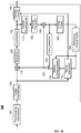
- FIG. 19 illustrates a block diagram of a video decoder 200.
- a bitstream is decoded by the decoder elements as described below.
- Video decoder 200 generally performs a decoding pass reciprocal to the encoding pass as described in FIG. 18 .
- the encoder 100 also generally performs video decoding as part of encoding video data.
- the input of the decoder includes a video bitstream, which can be generated by video encoder 100.
- the bitstream is first entropy decoded (230) to obtain transform coefficients, motion vectors, and other coded information.
- the picture partition information indicates how the picture is partitioned.
- the decoder may therefore divide (235) the picture according to the decoded picture partitioning information.
- the transform coefficients are de-quantized (240) and inverse transformed (250) to decode the prediction residuals.
- Combining (255) the decoded prediction residuals and the predicted block an image block is reconstructed.
- the predicted block can be obtained (270) from intra prediction (260) or motion-compensated prediction (i.e., inter prediction) (275).
- In-loop filters (265) are applied to the reconstructed image.
- the filtered image is stored at a reference picture buffer (280).
- the decoded picture can further go through post-decoding processing (285), for example, an inverse color transform (e.g. conversion from YCbCr 4:2:0 to RGB 4:4:4) or an inverse remapping performing the inverse of the remapping process performed in the pre-encoding processing (101).
- post-decoding processing can use metadata derived in the pre-encoding processing and signaled in the bitstream.
- FIG. 20 illustrates a block diagram of an example of a system in which various aspects and embodiments are implemented.
- System 1000 can be embodied as a device including the various components described below and is configured to perform one or more of the aspects described in this document. Examples of such devices, include, but are not limited to, various electronic devices such as personal computers, laptop computers, smartphones, tablet computers, digital multimedia set top boxes, digital television receivers, personal video recording systems, connected home appliances, and servers.
- Elements of system 1000, singly or in combination can be embodied in a single integrated circuit (IC), multiple ICs, and/or discrete components.
- the processing and encoder/decoder elements of system 1000 are distributed across multiple ICs and/or discrete components.
- system 1000 is communicatively coupled to one or more other systems, or other electronic devices, via, for example, a communications bus or through dedicated input and/or output ports.
- system 1000 is configured to implement one or more of the aspects described in this document.
- the system 1000 includes at least one processor 1010 configured to execute instructions loaded therein for implementing, for example, the various aspects described in this document.
- Processor 1010 can include embedded memory, input output interface, and various other circuitries as known in the art.
- the system 1000 includes at least one memory 1020 (e.g., a volatile memory device, and/or a non-volatile memory device).
- System 1000 includes a storage device 1040, which can include non-volatile memory and/or volatile memory, including, but not limited to, Electrically Erasable Programmable Read-Only Memory (EEPROM), Read-Only Memory (ROM), Programmable Read-Only Memory (PROM), Random Access Memory (RAM), Dynamic Random Access Memory (DRAM), Static Random Access Memory (SRAM), flash, magnetic disk drive, and/or optical disk drive.
- the storage device 1040 can include an internal storage device, an attached storage device (including detachable and non-detachable storage devices), and/or a network accessible storage device, as non-limiting examples.
- System 1000 includes an encoder/decoder module 1030 configured, for example, to process data to provide an encoded video or decoded video, and the encoder/decoder module 1030 can include its own processor and memory.
- the encoder/decoder module 1030 represents module(s) that can be included in a device to perform the encoding and/or decoding functions. As is known, a device can include one or both of the encoding and decoding modules. Additionally, encoder/decoder module 1030 can be implemented as a separate element of system 1000 or can be incorporated within processor 1010 as a combination of hardware and software as known to those skilled in the art.
- processor 1010 Program code to be loaded onto processor 1010 or encoder/decoder 1030 to perform the various aspects described in this document can be stored in storage device 1040 and subsequently loaded onto memory 1020 for execution by processor 1010.
- processor 1010, memory 1020, storage device 1040, and encoder/decoder module 1030 can store one or more of various items during the performance of the processes described in this document.
- Such stored items can include, but are not limited to, the input video, the decoded video or portions of the decoded video, the bitstream, matrices, variables, and intermediate or final results from the processing of equations, formulas, operations, and operational logic.
- memory inside of the processor 1010 and/or the encoder/decoder module 1030 is used to store instructions and to provide working memory for processing that is needed during encoding or decoding.
- a memory external to the processing device (for example, the processing device can be either the processor 1010 or the encoder/decoder module 1030) is used for one or more of these functions.
- the external memory can be the memory 1020 and/or the storage device 1040, for example, a dynamic volatile memory and/or a non-volatile flash memory.
- an external non-volatile flash memory is used to store the operating system of, for example, a television.
- a fast external dynamic volatile memory such as a RAM is used as working memory for video coding and decoding operations, such as for MPEG-2 (MPEG refers to the Moving Picture Experts Group, MPEG-2 is also referred to as ISO/IEC 13818, and 13818-1 is also known as H.222, and 13818-2 is also known as H.262), HEVC (HEVC refers to High Efficiency Video Coding, also known as H.265 and MPEG-H Part 2), or VVC (Versatile Video Coding, a new standard being developed by JVET, the Joint Video Experts Team).
- MPEG-2 MPEG refers to the Moving Picture Experts Group
- MPEG-2 is also referred to as ISO/IEC 13818
- 13818-1 is also known as H.222
- 13818-2 is also known as H.262
- HEVC High Efficiency Video Coding
- VVC Very Video Coding
- the input to the elements of system 1000 can be provided through various input devices as indicated in block 1130.
- Such input devices include, but are not limited to, (i) a radio frequency (RF) portion that receives an RF signal transmitted, for example, over the air by a broadcaster, (ii) a Component (COMP) input terminal (or a set of COMP input terminals), (iii) a Universal Serial Bus (USB) input terminal, and/or (iv) a High Definition Multimedia Interface (HDMI) input terminal.
- RF radio frequency
- COMP Component
- USB Universal Serial Bus
- HDMI High Definition Multimedia Interface
- Other examples, not shown in FIG. 20 include composite video.
- the input devices of block 1130 have associated respective input processing elements as known in the art.
- the RF portion can be associated with elements suitable for (i) selecting a desired frequency (also referred to as selecting a signal, or band-limiting a signal to a band of frequencies), (ii) downconverting the selected signal, (iii) band-limiting again to a narrower band of frequencies to select (for example) a signal frequency band which can be referred to as a channel in certain embodiments, (iv) demodulating the downconverted and band-limited signal, (v) performing error correction, and (vi) demultiplexing to select the desired stream of data packets.
- the RF portion of various embodiments includes one or more elements to perform these functions, for example, frequency selectors, signal selectors, band-limiters, channel selectors, filters, downconverters, demodulators, error correctors, and demultiplexers.
- the RF portion can include a tuner that performs various of these functions, including, for example, downconverting the received signal to a lower frequency (for example, an intermediate frequency or a near-baseband frequency) or to baseband.
- the RF portion and its associated input processing element receives an RF signal transmitted over a wired (for example, cable) medium, and performs frequency selection by filtering, downconverting, and filtering again to a desired frequency band.
- Adding elements can include inserting elements in between existing elements, such as, for example, inserting amplifiers and an analog-to-digital converter.
- the RF portion includes an antenna.
- USB and/or HDMI terminals can include respective interface processors for connecting system 1000 to other electronic devices across USB and/or HDMI connections.
- various aspects of input processing for example, Reed-Solomon error correction
- aspects of USB or HDMI interface processing can be implemented within separate interface ICs or within processor 1010 as necessary.
- the demodulated, error corrected, and demultiplexed stream is provided to various processing elements, including, for example, processor 1010, and encoder/decoder 1030 operating in combination with the memory and storage elements to process the datastream as necessary for presentation on an output device.
- Various elements of system 1000 can be provided within an integrated housing, Within the integrated housing, the various elements can be interconnected and transmit data therebetween using suitable connection arrangement, for example, an internal bus as known in the art, including the Inter-IC (I2C) bus, wiring, and printed circuit boards.
- I2C Inter-IC
- the system 1000 includes communication interface 1050 that enables communication with other devices via communication channel 1060.
- the communication interface 1050 can include, but is not limited to, a transceiver configured to transmit and to receive data over communication channel 1060.
- the communication interface 1050 can include, but is not limited to, a modem or network card and the communication channel 1060 can be implemented, for example, within a wired and/or a wireless medium.
- Wi-Fi Wireless Fidelity
- IEEE 802.11 IEEE refers to the Institute of Electrical and Electronics Engineers
- the Wi-Fi signal of these embodiments is received over the communications channel 1060 and the communications interface 1050 which are adapted for Wi-Fi communications.
- the communications channel 1060 of these embodiments is typically connected to an access point or router that provides access to external networks including the Internet for allowing streaming applications and other over-the-top communications.
- Other embodiments provide streamed data to the system 1000 using a set-top box that delivers the data over the HDMI connection of the input block 1130.
- Still other embodiments provide streamed data to the system 1000 using the RF connection of the input block 1130.
- various embodiments provide data in a non-streaming manner.
- various embodiments use wireless networks other than Wi-Fi, for example a cellular network or a Bluetooth network.
- the system 1000 can provide an output signal to various output devices, including a display 1100, speakers 1110, and other peripheral devices 1120.
- the display 1100 of various embodiments includes one or more of, for example, a touchscreen display, an organic light-emitting diode (OLED) display, a curved display, and/or a foldable display.
- the display 1100 can be for a television, a tablet, a laptop, a cell phone (mobile phone), or other device.
- the display 1100 can also be integrated with other components (for example, as in a smart phone), or separate (for example, an external monitor for a laptop).
- the other peripheral devices 1120 include, in various examples of embodiments, one or more of a stand-alone digital video disc (or digital versatile disc) (DVR, for both terms), a disk player, a stereo system, and/or a lighting system.
- Various embodiments use one or more peripheral devices 1120 that provide a function based on the output of the system 1000. For example, a disk player performs the function of playing the output of the system 1000.
- control signals are communicated between the system 1000 and the display 1100, speakers 1110, or other peripheral devices 1120 using signaling such as AV.Link, Consumer Electronics Control (CEC), or other communications protocols that enable device-to-device control with or without user intervention.
- the output devices can be communicatively coupled to system 1000 via dedicated connections through respective interfaces 1070, 1080, and 1090. Alternatively, the output devices can be connected to system 1000 using the communications channel 1060 via the communications interface 1050.
- the display 1100 and speakers 1110 can be integrated in a single unit with the other components of system 1000 in an electronic device such as, for example, a television.
- the display interface 1070 includes a display driver, such as, for example, a timing controller (T Con) chip.
- the display 1100 and speaker 1110 can alternatively be separate from one or more of the other components, for example, if the RF portion of input 1130 is part of a separate set-top box.
- the output signal can be provided via dedicated output connections, including, for example, HDMI ports, USB ports, or COMP outputs.
- the embodiments can be carried out by computer software implemented by the processor 1010 or by hardware, or by a combination of hardware and software. As a non-limiting example, the embodiments can be implemented by one or more integrated circuits.
- the memory 1020 can be of any type appropriate to the technical environment and can be implemented using any appropriate data storage technology, such as optical memory devices, magnetic memory devices, semiconductor-based memory devices, fixed memory, and removable memory, as non-limiting examples.
- the processor 1010 can be of any type appropriate to the technical environment, and can encompass one or more of microprocessors, general purpose computers, special purpose computers, and processors based on a multi-core architecture, as non-limiting examples.
- Decoding can encompass all or part of the processes performed, for example, on a received encoded sequence in order to produce a final output suitable for display.
- processes include one or more of the processes typically performed by a decoder, for example, entropy decoding, inverse quantization, inverse transformation, and differential decoding.
- processes also, or alternatively, include processes performed by a decoder of various implementations described in this application, for example, affine motion compensation with normalized storage of affine model for memory reduction.
- decoding refers only to entropy decoding
- decoding refers only to differential decoding
- decoding refers to a combination of entropy decoding and differential decoding.
- such processes include one or more of the processes typically performed by an encoder, for example, partitioning, differential encoding, transformation, quantization, and entropy encoding.
- such processes also, or alternatively, include processes performed by an encoder of various implementations described in this application, for example, affine motion compensation with normalized storage of affine model for memory reduction.
- encoding refers only to entropy encoding
- encoding refers only to differential encoding
- encoding refers to a combination of differential encoding and entropy encoding.
- syntax elements as used herein, for example, Affine mode flag are descriptive terms. As such, they do not preclude the use of other syntax element names.
- the implementations and aspects described herein can be implemented in, for example, a method or a process, an apparatus, a software program, a data stream, or a signal. Even if only discussed in the context of a single form of implementation (for example, discussed only as a method), the implementation of features discussed can also be implemented in other forms (for example, an apparatus or program).
- An apparatus can be implemented in, for example, appropriate hardware, software, and firmware.
- the methods can be implemented in, for example, a processor, which refers to processing devices in general, including, for example, a computer, a microprocessor, an integrated circuit, or a programmable logic device. Processors also include communication devices, such as, for example, computers, cell phones, portable/personal digital assistants ("PDAs”), and other devices that facilitate communication of information between end-users.
- PDAs portable/personal digital assistants
- references to "one embodiment” or “an embodiment” or “one implementation” or “an implementation”, as well as other variations thereof, means that a particular feature, structure, characteristic, and so forth described in connection with the embodiment is included in at least one embodiment.
- the appearances of the phrase “in one embodiment” or “in an embodiment” or “in one implementation” or “in an implementation”, as well any other variations, appearing in various places throughout this application are not necessarily all referring to the same embodiment.
- Determining the information can include one or more of, for example, estimating the information, calculating the information, predicting the information, or retrieving the information from memory.
- Accessing the information can include one or more of, for example, receiving the information, retrieving the information (for example, from memory), storing the information, moving the information, copying the information, calculating the information, determining the information, predicting the information, or estimating the information.
- this application may refer to "receiving" various pieces of information.
- Receiving is, as with “accessing”, intended to be a broad term.
- Receiving the information can include one or more of, for example, accessing the information, or retrieving the information (for example, from memory).
- “receiving” is typically involved, in one way or another, during operations such as, for example, storing the information, processing the information, transmitting the information, moving the information, copying the information, erasing the information, calculating the information, determining the information, predicting the information, or estimating the information.
- such phrasing is intended to encompass the selection of the first listed option (A) only, or the selection of the second listed option (B) only, or the selection of the third listed option (C) only, or the selection of the first and the second listed options (A and B) only, or the selection of the first and third listed options (A and C) only, or the selection of the second and third listed options (B and C) only, or the selection of all three options (A and B and C).
- This may be extended, as is clear to one of ordinary skill in this and related arts, for as many items as are listed.
- the word "signal" refers to, among other things, indicating something to a corresponding decoder.
- the encoder signals a particular one of a plurality of parameters for normalized affine model storage.
- the same parameter is used at both the encoder side and the decoder side.
- an encoder can transmit (explicit signaling) a particular parameter to the decoder so that the decoder can use the same particular parameter.
- signaling can be used without transmitting (implicit signaling) to simply allow the decoder to know and select the particular parameter.
- signaling can be accomplished in a variety of ways. For example, one or more syntax elements, flags, and so forth are used to signal information to a corresponding decoder in various embodiments. While the preceding relates to the verb form of the word "signal”, the word “signal” can also be used herein as a noun.
- implementations can produce a variety of signals formatted to carry information that can be, for example, stored or transmitted.
- the information can include, for example, instructions for performing a method, or data produced by one of the described implementations.
- a signal can be formatted to carry the bitstream of a described embodiment.
- Such a signal can be formatted, for example, as an electromagnetic wave (for example, using a radio frequency portion of spectrum) or as a baseband signal.
- the formatting can include, for example, encoding a data stream and modulating a carrier with the encoded data stream.
- the information that the signal carries can be, for example, analog or digital information.
- the signal can be transmitted over a variety of different wired or wireless links, as is known.
- the signal can be stored on a processor-readable medium.
- embodiments can be provided alone or in any combination, across various claim categories and types. Further, embodiments can include one or more of the following features, devices, or aspects, alone or in any combination, across various claim categories and types:
Landscapes
- Engineering & Computer Science (AREA)
- Multimedia (AREA)
- Signal Processing (AREA)
- Compression Or Coding Systems Of Tv Signals (AREA)
Priority Applications (1)
| Application Number | Priority Date | Filing Date | Title |
|---|---|---|---|
| EP19305266.9A EP3706421A1 (fr) | 2019-03-07 | 2019-03-07 | Procédé et appareil de codage et de décodage vidéo à base de compensation de mouvement affine |
Applications Claiming Priority (1)
| Application Number | Priority Date | Filing Date | Title |
|---|---|---|---|
| EP19305266.9A EP3706421A1 (fr) | 2019-03-07 | 2019-03-07 | Procédé et appareil de codage et de décodage vidéo à base de compensation de mouvement affine |
Publications (1)
| Publication Number | Publication Date |
|---|---|
| EP3706421A1 true EP3706421A1 (fr) | 2020-09-09 |
Family
ID=65818470
Family Applications (1)
| Application Number | Title | Priority Date | Filing Date |
|---|---|---|---|
| EP19305266.9A Withdrawn EP3706421A1 (fr) | 2019-03-07 | 2019-03-07 | Procédé et appareil de codage et de décodage vidéo à base de compensation de mouvement affine |
Country Status (1)
| Country | Link |
|---|---|
| EP (1) | EP3706421A1 (fr) |
Cited By (4)
| Publication number | Priority date | Publication date | Assignee | Title |
|---|---|---|---|---|
| WO2023097019A1 (fr) * | 2021-11-23 | 2023-06-01 | Beijing Dajia Internet Information Technology Co., Ltd. | Procédés et dispositifs de dérivation de candidats pour un mode de fusion affine dans un codage vidéo |
| WO2023133160A1 (fr) * | 2022-01-04 | 2023-07-13 | Beijing Dajia Internet Information Technology Co., Ltd. | Procédés et dispositifs de dérivation de candidats pour un mode de fusion affine en codage vidéo |
| WO2023220444A1 (fr) * | 2022-05-13 | 2023-11-16 | Beijing Dajia Internet Information Technology Co., Ltd. | Procédés et dispositifs de dérivation de candidats pour un mode de fusion affine dans le codage vidéo |
| WO2024010831A1 (fr) * | 2022-07-05 | 2024-01-11 | Beijing Dajia Internet Information Technology Co., Ltd. | Procédés et dispositifs de dérivation de candidats pour un mode de fusion affine dans un codage vidéo |
Citations (1)
| Publication number | Priority date | Publication date | Assignee | Title |
|---|---|---|---|---|
| WO2017157259A1 (fr) * | 2016-03-15 | 2017-09-21 | Mediatek Inc. | Procédé et appareil de codage vidéo avec compensation de mouvement affine |
-
2019
- 2019-03-07 EP EP19305266.9A patent/EP3706421A1/fr not_active Withdrawn
Patent Citations (1)
| Publication number | Priority date | Publication date | Assignee | Title |
|---|---|---|---|---|
| WO2017157259A1 (fr) * | 2016-03-15 | 2017-09-21 | Mediatek Inc. | Procédé et appareil de codage vidéo avec compensation de mouvement affine |
Non-Patent Citations (3)
| Title |
|---|
| LI LI ET AL: "An affine motion compensation framework for high efficiency video coding", 2015 IEEE INTERNATIONAL SYMPOSIUM ON CIRCUITS AND SYSTEMS (ISCAS), IEEE, 24 May 2015 (2015-05-24), pages 525 - 528, XP033183218, DOI: 10.1109/ISCAS.2015.7168686 * |
| PHAM VAN (QUALCOMM) L ET AL: "CE2.4.3: Affine restriction for worst-case memory bandwidth reduction", no. JVET-M0150, 10 January 2019 (2019-01-10), XP030201296, Retrieved from the Internet <URL:http://phenix.int-evry.fr/jvet/doc_end_user/documents/13_Marrakech/wg11/JVET-M0150-v2.zip> [retrieved on 20190110] * |
| YANG H ET AL: "Description of Core Experiment 4 (CE4): Inter prediction and motion vector coding", 10. JVET MEETING; 10-4-2018 - 20-4-2018; SAN DIEGO; (THE JOINT VIDEO EXPLORATION TEAM OF ISO/IEC JTC1/SC29/WG11 AND ITU-T SG.16 ); URL: HTTP://PHENIX.INT-EVRY.FR/JVET/,, no. JVET-J1024-v3, 28 May 2018 (2018-05-28), XP030151319 * |
Cited By (4)
| Publication number | Priority date | Publication date | Assignee | Title |
|---|---|---|---|---|
| WO2023097019A1 (fr) * | 2021-11-23 | 2023-06-01 | Beijing Dajia Internet Information Technology Co., Ltd. | Procédés et dispositifs de dérivation de candidats pour un mode de fusion affine dans un codage vidéo |
| WO2023133160A1 (fr) * | 2022-01-04 | 2023-07-13 | Beijing Dajia Internet Information Technology Co., Ltd. | Procédés et dispositifs de dérivation de candidats pour un mode de fusion affine en codage vidéo |
| WO2023220444A1 (fr) * | 2022-05-13 | 2023-11-16 | Beijing Dajia Internet Information Technology Co., Ltd. | Procédés et dispositifs de dérivation de candidats pour un mode de fusion affine dans le codage vidéo |
| WO2024010831A1 (fr) * | 2022-07-05 | 2024-01-11 | Beijing Dajia Internet Information Technology Co., Ltd. | Procédés et dispositifs de dérivation de candidats pour un mode de fusion affine dans un codage vidéo |
Similar Documents
| Publication | Publication Date | Title |
|---|---|---|
| US20220159277A1 (en) | Method and apparatus for video encoding and decoding with subblock based local illumination compensation | |
| EP3706421A1 (fr) | Procédé et appareil de codage et de décodage vidéo à base de compensation de mouvement affine | |
| EP3703366A1 (fr) | Procédé et dispositif de codage et de décodage d'images | |
| EP4218240A1 (fr) | Prédiction de correspondance de modèles pour codage vidéo polyvalent | |
| CN113170210A (zh) | 视频编码和解码中的仿射模式信令 | |
| EP4005210A1 (fr) | Procédé et appareil de codage et de décodage vidéo avec prédiction intra basée sur une matrice | |
| JP2024059909A (ja) | 画像エンコーディングおよびデコーディングのための方法およびデバイス | |
| EP3850849A1 (fr) | Candidats affines temporels virtuels améliorés | |
| US11973969B2 (en) | Method and apparatus for video encoding and decoding using list of predictor candidates | |
| WO2020005572A1 (fr) | Candidats affine temporels virtuels | |
| EP3824624A1 (fr) | Intra-prédiction grand angle, et combinaison d'intra-prédiction dépendant de la position | |
| US11375202B2 (en) | Translational and affine candidates in a unified list | |
| EP4055824A1 (fr) | Prédiction intra profonde d'un bloc d'image | |
| WO2020112451A1 (fr) | Combinaison d'affines candidats | |
| US20220264147A1 (en) | Hmvc for affine and sbtmvp motion vector prediction modes | |
| US11997279B2 (en) | Affine mode signaling in video encoding and decoding | |
| EP3606075A1 (fr) | Candidats vecteurs de mouvement affines temporels virtuels | |
| WO2024033116A1 (fr) | Prédiction de limite de mode de partition géométrique | |
| WO2023194103A1 (fr) | Dérivation intra-mode temporelle | |
| EP4193593A1 (fr) | Combinaison d'abt avec des outils de codage vvc à base de sous-blocs | |
| EP4289141A1 (fr) | Compensation spatiale d'éclairage local | |
| WO2022214244A1 (fr) | Copie intra-bloc avec adaptation de modèle pour codage et décodage vidéo | |
| EP3891984A1 (fr) | Procédé et dispositif de codage et de décodage d'image |
Legal Events
| Date | Code | Title | Description |
|---|---|---|---|
| PUAI | Public reference made under article 153(3) epc to a published international application that has entered the european phase |
Free format text: ORIGINAL CODE: 0009012 |
|
| STAA | Information on the status of an ep patent application or granted ep patent |
Free format text: STATUS: THE APPLICATION HAS BEEN PUBLISHED |
|
| AK | Designated contracting states |
Kind code of ref document: A1 Designated state(s): AL AT BE BG CH CY CZ DE DK EE ES FI FR GB GR HR HU IE IS IT LI LT LU LV MC MK MT NL NO PL PT RO RS SE SI SK SM TR |
|
| AX | Request for extension of the european patent |
Extension state: BA ME |
|
| STAA | Information on the status of an ep patent application or granted ep patent |
Free format text: STATUS: THE APPLICATION IS DEEMED TO BE WITHDRAWN |
|
| 18D | Application deemed to be withdrawn |
Effective date: 20210310 |