EP3706366A1 - Service support system and method, intelligent service ability adjustment system and method, and computer device - Google Patents
Service support system and method, intelligent service ability adjustment system and method, and computer device Download PDFInfo
- Publication number
- EP3706366A1 EP3706366A1 EP18873086.5A EP18873086A EP3706366A1 EP 3706366 A1 EP3706366 A1 EP 3706366A1 EP 18873086 A EP18873086 A EP 18873086A EP 3706366 A1 EP3706366 A1 EP 3706366A1
- Authority
- EP
- European Patent Office
- Prior art keywords
- service level
- power
- service
- real
- adjustment
- Prior art date
- Legal status (The legal status is an assumption and is not a legal conclusion. Google has not performed a legal analysis and makes no representation as to the accuracy of the status listed.)
- Granted
Links
Images


Classifications
-
- H—ELECTRICITY
- H04—ELECTRIC COMMUNICATION TECHNIQUE
- H04L—TRANSMISSION OF DIGITAL INFORMATION, e.g. TELEGRAPHIC COMMUNICATION
- H04L43/00—Arrangements for monitoring or testing data switching networks
- H04L43/16—Threshold monitoring
-
- H—ELECTRICITY
- H04—ELECTRIC COMMUNICATION TECHNIQUE
- H04L—TRANSMISSION OF DIGITAL INFORMATION, e.g. TELEGRAPHIC COMMUNICATION
- H04L41/00—Arrangements for maintenance, administration or management of data switching networks, e.g. of packet switching networks
- H04L41/06—Management of faults, events, alarms or notifications
- H04L41/0631—Management of faults, events, alarms or notifications using root cause analysis; using analysis of correlation between notifications, alarms or events based on decision criteria, e.g. hierarchy, tree or time analysis
-
- H—ELECTRICITY
- H04—ELECTRIC COMMUNICATION TECHNIQUE
- H04L—TRANSMISSION OF DIGITAL INFORMATION, e.g. TELEGRAPHIC COMMUNICATION
- H04L41/00—Arrangements for maintenance, administration or management of data switching networks, e.g. of packet switching networks
- H04L41/50—Network service management, e.g. ensuring proper service fulfilment according to agreements
- H04L41/5003—Managing SLA; Interaction between SLA and QoS
- H04L41/5009—Determining service level performance parameters or violations of service level contracts, e.g. violations of agreed response time or mean time between failures [MTBF]
-
- H—ELECTRICITY
- H04—ELECTRIC COMMUNICATION TECHNIQUE
- H04L—TRANSMISSION OF DIGITAL INFORMATION, e.g. TELEGRAPHIC COMMUNICATION
- H04L41/00—Arrangements for maintenance, administration or management of data switching networks, e.g. of packet switching networks
- H04L41/50—Network service management, e.g. ensuring proper service fulfilment according to agreements
- H04L41/5003—Managing SLA; Interaction between SLA and QoS
- H04L41/5019—Ensuring fulfilment of SLA
- H04L41/5025—Ensuring fulfilment of SLA by proactively reacting to service quality change, e.g. by reconfiguration after service quality degradation or upgrade
-
- H—ELECTRICITY
- H04—ELECTRIC COMMUNICATION TECHNIQUE
- H04L—TRANSMISSION OF DIGITAL INFORMATION, e.g. TELEGRAPHIC COMMUNICATION
- H04L43/00—Arrangements for monitoring or testing data switching networks
- H04L43/04—Processing captured monitoring data, e.g. for logfile generation
-
- B—PERFORMING OPERATIONS; TRANSPORTING
- B60—VEHICLES IN GENERAL
- B60L—PROPULSION OF ELECTRICALLY-PROPELLED VEHICLES; SUPPLYING ELECTRIC POWER FOR AUXILIARY EQUIPMENT OF ELECTRICALLY-PROPELLED VEHICLES; ELECTRODYNAMIC BRAKE SYSTEMS FOR VEHICLES IN GENERAL; MAGNETIC SUSPENSION OR LEVITATION FOR VEHICLES; MONITORING OPERATING VARIABLES OF ELECTRICALLY-PROPELLED VEHICLES; ELECTRIC SAFETY DEVICES FOR ELECTRICALLY-PROPELLED VEHICLES
- B60L53/00—Methods of charging batteries, specially adapted for electric vehicles; Charging stations or on-board charging equipment therefor; Exchange of energy storage elements in electric vehicles
- B60L53/60—Monitoring or controlling charging stations
-
- Y—GENERAL TAGGING OF NEW TECHNOLOGICAL DEVELOPMENTS; GENERAL TAGGING OF CROSS-SECTIONAL TECHNOLOGIES SPANNING OVER SEVERAL SECTIONS OF THE IPC; TECHNICAL SUBJECTS COVERED BY FORMER USPC CROSS-REFERENCE ART COLLECTIONS [XRACs] AND DIGESTS
- Y02—TECHNOLOGIES OR APPLICATIONS FOR MITIGATION OR ADAPTATION AGAINST CLIMATE CHANGE
- Y02T—CLIMATE CHANGE MITIGATION TECHNOLOGIES RELATED TO TRANSPORTATION
- Y02T10/00—Road transport of goods or passengers
- Y02T10/60—Other road transportation technologies with climate change mitigation effect
- Y02T10/70—Energy storage systems for electromobility, e.g. batteries
-
- Y—GENERAL TAGGING OF NEW TECHNOLOGICAL DEVELOPMENTS; GENERAL TAGGING OF CROSS-SECTIONAL TECHNOLOGIES SPANNING OVER SEVERAL SECTIONS OF THE IPC; TECHNICAL SUBJECTS COVERED BY FORMER USPC CROSS-REFERENCE ART COLLECTIONS [XRACs] AND DIGESTS
- Y02—TECHNOLOGIES OR APPLICATIONS FOR MITIGATION OR ADAPTATION AGAINST CLIMATE CHANGE
- Y02T—CLIMATE CHANGE MITIGATION TECHNOLOGIES RELATED TO TRANSPORTATION
- Y02T10/00—Road transport of goods or passengers
- Y02T10/60—Other road transportation technologies with climate change mitigation effect
- Y02T10/7072—Electromobility specific charging systems or methods for batteries, ultracapacitors, supercapacitors or double-layer capacitors
-
- Y—GENERAL TAGGING OF NEW TECHNOLOGICAL DEVELOPMENTS; GENERAL TAGGING OF CROSS-SECTIONAL TECHNOLOGIES SPANNING OVER SEVERAL SECTIONS OF THE IPC; TECHNICAL SUBJECTS COVERED BY FORMER USPC CROSS-REFERENCE ART COLLECTIONS [XRACs] AND DIGESTS
- Y02—TECHNOLOGIES OR APPLICATIONS FOR MITIGATION OR ADAPTATION AGAINST CLIMATE CHANGE
- Y02T—CLIMATE CHANGE MITIGATION TECHNOLOGIES RELATED TO TRANSPORTATION
- Y02T90/00—Enabling technologies or technologies with a potential or indirect contribution to GHG emissions mitigation
- Y02T90/10—Technologies relating to charging of electric vehicles
- Y02T90/12—Electric charging stations
Definitions
- the invention relates to the field of powering up, and more particularly to a service support system for a power-up device, a service capability intelligent adjustment system, a service support method for a power-up device, a service capability intelligent adjustment method in the service capability intelligent adjustment system, and a computer device.
- the invention is implemented to overcome the above-mentioned shortcomings or other shortcomings, and the adopted technical solutions are as follows.
- An embodiment of the invention provides a service support system for a power-up device, the system comprising: a receiving unit configured to receive real-time index data of the power-up device that is collected at a certain frequency from the power-up device; a storage unit configured to store the real-time index data received by the receiving unit; a determination unit configured to determine, based on the real-time index data stored in the storage unit, whether a service level intelligent adjustment condition is reached; and a service level adjustment unit configured to intelligently adjust the service level of the power-up device based on a determination result of the determination unit.
- the determination unit is configured to compare the real-time index data stored in the storage unit individually with a preset safety threshold, and determine, when a certain real-time index data meets a preset service level adjustment trigger condition, whether the data stored in the storage unit and starting from the real-time index data within m consecutive data collection cycles meets a preset service level recovery condition, and if the service level recovery condition is not met, determine whether the data within the first n data collection cycles of the m data collection cycles meets a preset service level degradation condition, where m and n both are positive integers and m ⁇ n; and the service level adjustment unit is configured to recover the service level of the power-up device when the determination unit determines that the service level recovery condition is met, degrade the service level of the power-up device when the determination unit determines that the service level recovery condition is not met but the service level degradation condition is met, and maintain the service level of the power-up device as it is when the determination unit determines that neither the service level recovery condition
- the service level adjustment unit is configured to maintain, when the determination unit determines that the service level recovery condition is met and the current service level of the power-up device is the highest service level that cannot be further upgraded, the service level of the power-up device as it is.
- the service level adjustment unit is configured to shut down, when the determination unit determines that the service level degradation condition is met and the current service level of the power-up device is the lowest service level that cannot be further degraded, the service of the power-up device.
- the system further comprises: a display unit configured to display the service level of the power-up device that is obtained after adjustment by the service level adjustment unit.
- the system further comprises: a service level notification unit configured to notify the power-up device of the service level obtained after adjustment by the service level adjustment unit.
- system further comprises: a data collection instruction generation unit configured to generate an instruction for collecting the real-time index data of the power-up device; and a sending unit configured to send the generated instruction to the power-up device.
- An embodiment of the invention provides a system for intelligent adjustment of service capabilities, comprising: at least one power-up device, each of which comprising: a data collection unit configured to collect its own real-time index data at a certain frequency; and a sending unit configured to send the real-time index data; and the service support system according to an embodiment of the invention, which interacts with the at least one power-up device in a wired or wireless manner.
- An embodiment of the invention provides a service support method for a power-up device, the method comprising: a receiving step for receiving real-time index data of the power-up device that is collected at a certain frequency from the power-up device; a storage step for storing the real-time index data received in the receiving step; a determination step for determining, based on the stored real-time index data, whether a service level intelligent adjustment condition is reached; and a service level adjustment step for intelligently adjusting the service level of the power-up device based on a determination result of the determination step.
- the stored real-time index data is compared individually with a preset safety threshold, and when a certain real-time index data meets a preset service level adjustment trigger condition, it is determined whether the stored data starting from the real-time index data within m consecutive data collection cycles meets a preset service level recovery condition, and if the service level recovery condition is not met, it is determined whether the data within the first n data collection cycles of the m data collection cycles meets a preset service level degradation condition, where m and n both are positive integers and m ⁇ n; and in the service level adjustment step, the service level of the power-up device is recovered when it is determined in the determination step that the service level recovery condition is met, the service level of the power-up device is degraded when it is determined in the determination step that the service level recovery condition is not met but the service level degradation condition is met, and the service level of the power-up device is maintained as it is when it is determined in the determination step that neither the
- the service level adjustment step when it is determined in the determination step that the service level recovery condition is met and the current service level of the power-up device is the highest service level that cannot be further upgraded, the service level of the power-up device is maintained as it is.
- the service level adjustment step when it is determined in the determination step that the service level degradation condition is met and the current service level of the power-up device is the lowest service level that cannot be further degraded, the service of the power-up device is shut down.
- the method further comprises: a display step for displaying the service level of the power-up device that is obtained after adjustment in the service level adjustment step.
- the method further comprises: a service level notification step for notifying the power-up device of the service level obtained after adjustment in the service level adjustment step.
- the method further comprises: a data collection instruction generation step for generating an instruction for collecting the real-time index data of the power-up device; and a sending step for sending the generated instruction to the power-up device.
- An embodiment of the invention provides a method for intelligent adjustment of service capabilities in a service capability intelligent adjustment system.
- the system comprises at least one power-up device and a service support system for the power-up device.
- the method comprises: a data collection step for collecting, by each of the at least one power-up device, its own real-time index data at a certain frequency; a sending step for sending, by each of the at least one power-up device, the real-time index data to the service support system; a receiving step for receiving, by the service support system, the real-time index data from each of the at least one power-up device; a storage step for storing for each of the at least one power-up device, by the service support system, the real-time index data received in the receiving step; a determination step for determining for each of the at least one power-up device, by the service support system based on the stored corresponding real-time index data, whether a service level adjustment condition is reached; and a service level adjustment step for intelligently adjusting for each of the at least one power
- the stored real-time index data is compared individually with a preset safety threshold, and when a certain real-time index data meets a preset service level adjustment trigger condition, it is determined whether the stored data starting from the real-time index data within m consecutive data collection cycles meets a preset service level recovery condition, and if the service level recovery condition is not met, it is determined whether the data within the first n data collection cycles of the m data collection cycles meets a preset service level degradation condition, where m and n both are positive integers and m ⁇ n; and in the service level adjustment step, the service level of the power-up device is recovered when it is determined in the determination step that the service level recovery condition is met, the service level of the power-up device is degraded when it is determined in the determination step that the service level recovery condition is not met but the service level degradation condition is met, and the service level of the power-up device
- the service level adjustment step when it is determined in the determination step that the service level recovery condition is met and the current service level of the power-up device is the highest service level that cannot be further upgraded, the service level of the power-up device is maintained as it is.
- the service level adjustment step when it is determined in the determination step that the service level degradation condition is met and the current service level of the power-up device is the lowest service level that cannot be further degraded, the service of the power-up device is shut down.
- the method further comprises: a display step for displaying for each of the at least one power-up device, by the service support system, the service level obtained after adjustment in the service level adjustment step.
- the method further comprises: a service level notification step for notifying, by the service support system, each of the at least one power-up device of the service level obtained after adjustment in the service level adjustment step.
- the method further comprises: a data collection instruction generation step for generating, by the service support system, an instruction for collecting the real-time index data of the power-up device; and a sending step for sending, by the service support system, the generated instruction to the power-up device.
- An embodiment of the invention provides a computer device, comprising: a first memory configured to store therein real-time index data of a power-up device that is collected at a certain frequency; a second memory configured to store therein a program related to service support for the power-up device; and a processor configured to execute the program stored in the second memory so as to perform the following steps: a determination step for determining, based on the real-time index data stored in the first memory, whether a service level adjustment condition is reached; and a service level adjustment step for intelligently adjusting the service level of the power-up device based on a determination result of the determination step.
- the stored real-time index data is compared individually with a preset safety threshold, and when a certain real-time index data meets a preset service level adjustment trigger condition, it is determined whether the stored data starting from the real-time index data within m consecutive data collection cycles meets a preset service level recovery condition, and if the service level recovery condition is not met, it is determined whether the data within the first n data collection cycles of the m data collection cycles meets a preset service level degradation condition, where m and n both are positive integers and m ⁇ n; and in the service level adjustment step, the service level of the power-up device is recovered when it is determined in the determination step that the service level recovery condition is met, the service level of the power-up device is degraded when it is determined in the determination step that the service level recovery condition is not met but the service level degradation condition is met, and the service level of the power-up device is maintained as it is when it is determined in the determination step that neither the service
- the service level adjustment step when it is determined in the determination step that the service level recovery condition is met and the current service level of the power-up device is the highest service level that cannot be further upgraded, the service level of the power-up device is maintained as it is.
- the service level adjustment step when it is determined in the determination step that the service level degradation condition is met and the current service level of the power-up device is the lowest service level that cannot be further degraded, the service of the power-up device is shut down.
- the processor further executes the program to perform the following steps: a data collection instruction generation step for generating an instruction for collecting the real-time index data of the power-up device; and a sending step for sending the generated instruction to the power-up device.
- a service support system for a power-up device, a service capability intelligent adjustment system, a service support method for a power-up device, a service capability intelligent adjustment method in the service capability intelligent adjustment system, and a computer device according to the invention will be described in further detail below in combination with the accompanying drawings. It should be noted that the following detailed description of embodiments are exemplary rather than limiting, and are intended to provide a basic understanding of the invention, and are not intended to confirm key or decisive elements of the invention or limit the scope of protection.
- FIG. 1 is a block diagram of a system for intelligent adjustment of service capabilities according to an embodiment of the invention.
- the system 1000 for intelligent adjustment of service capabilities shown in FIG. 1 is taken as an example for illustration.
- the system 1000 for intelligent adjustment of service capabilities is a system for intelligent adjustment of the service capabilities (i.e., service levels) of the power-up device.
- the "power-up device” referred to herein includes but is not limited to a battery swap station, a charging station, a mobile battery swap vehicle, a mobile charging vehicle, a charging pile, etc.
- the "intelligent adjustment of service capabilities (i.e., service level)” mentioned herein includes service level degradation, service level recovery, service level maintenance, etc.
- service level degradation means that, for example, when monitored real-time index data of the power-up device exceeds or falls below a threshold, or the power-up device generates an alarm or even fails, the service capability (i.e., service level) of the power-up device is strategically reduced to ensure that the power-up device can still provide part of the service instead of directly shutting down the service.
- the “service level recovery” means that, for example, the service capability (i.e., service level) of the power-up device is strategically recovered until the service capability is completely recovered (i.e., recovered to the highest service level that cannot be further upgraded) when monitored real-time index data of the power-up device shows that the state of the power-up device has improved, or the alarm of the power-up device is gradually eliminated, or the failure of the power-up device is gradually resolved.
- the service of power-up device can be graded as follows. Assuming that the power-up device can provide up to x batteries with power-up services, service levels of the power-up device can be divided into:
- L0 level is the highest service level mentioned above that cannot be further upgraded, while Lq level is the lowest service level that cannot be further degraded.
- the strategy for degrading the service level of the power-up device is divided into an initial service degradation strategy and a secondary service degradation strategy.
- the initial service degradation strategy the service level of the power-up device is degraded from the L0 level service to the L1 level service.
- the secondary service degradation strategy the service level is degraded step by step from the L1 level service to the Lq level service. If further degradation is required at this time, the service of the power-up device is shut down to stop the power-up services for all batteries.
- the strategy for recovering the service level of the power-up device is divided into an initial service recovery strategy and a secondary service recovery strategy.
- the initial service recovery strategy the service level of the power-up device is recovered from the Lq level service to the Lq-1 level service.
- the secondary service recovery strategy the service level is recovered step by step from the Lq-1 level service until the L0 level service. If further recovery is required at this time, it can only be maintained at the current L0 level service in view of the maximum number of batteries served by the power-up device.
- the service capability intelligent adjustment system 1000 comprises a service support system 100 and power-up devices 200a and 200b. Although only two power-up devices are depicted in FIG. 1 , it should be appreciated that the number of power-up devices is not limited to two, but may be one or more than three.
- the power-up devices 200a and 200b have the same structure.
- the power-up device 200a is taken as an example for illustration.
- the power-up device 200a comprises a data collection unit 201a and a sending unit 202a.
- the data collection unit 201a is configured to collect real-time index data of the power-up device at a certain frequency.
- the above-mentioned frequency for collecting data can be set by the power-up device itself, or can be preset by the service support system for each power-up device, and the above-mentioned frequency for collecting data can vary with type of the different real-time index data.
- the "real-time index data" referred to herein includes but is not limited to the temperature of a battery area of the power-up device, the humidity of the battery area of the power-up device, the power of the power-up device, etc.
- the monitored real-time index data can be set according to the functional attributes of the power-up device itself and a service target, and a safety threshold for the real-time index data can be preset.
- a safety threshold for the real-time index data can be preset.
- the temperature value k of the battery area of the power-up device is selected as the real-time index data to be monitored
- the collection frequency is 1 second/time
- the safety threshold is 35 degrees Celsius.
- the sending unit 202a is configured to send the real-time index data collected by the data collection unit 202a to the service support system 100.
- the service support system 100 interacts with the power-up devices 200a and 200b in a wired or wireless manner.
- the "wired manner” mentioned herein includes but is not limited to I2C, SPI, PS/2, Universal Serial Bus (USB), etc.
- the "wireless manner” mentioned herein includes but is not limited LTE, WCDMA, Bluetooth, RF, IRDA, etc.
- the specific structure of the service support system 100 is illustrated in FIG. 2 .
- the service support system 100 comprises a receiving unit 101, a storage unit 102, a determination unit 103, and a service level adjustment unit 104.
- the power-up device 200a in FIG. 1 is taken as an example for illustration.
- the receiving unit 101 is configured to receive real-time index data of the power-up device 200a that is collected at a certain frequency from the power-up device 200a.
- the storage unit 102 is configured to store the real-time index data of the power-up device 200a received by the receiving unit 101.
- the storage of the real-time index data can be in the order of collection for subsequent invocation.
- the determination unit 103 is configured to determine, based on the real-time index data of the power-up device 200a stored in the storage unit 102, whether a service level intelligent adjustment condition is reached.
- the "service level intelligent adjustment condition" referred to herein includes but is not limited to a service level recovery condition, a service level degradation condition, etc.
- the determination unit 103 may compare the real-time index data stored in the storage unit 102 individually with a preset safety threshold, and determine, when a certain real-time index data meets a preset service level adjustment trigger condition, whether the data stored in the storage unit 102 and starting from the real-time index data within m consecutive data collection cycles meets a preset service level recovery condition, and if the service level recovery condition is not met, determine whether the data within the first n data collection cycles of the m data collection cycles meets a preset service level degradation condition, where m and n both are positive integers and m ⁇ n.
- the "service level adjustment trigger condition" mentioned herein may be preset as, for example, the real-time index data (for example, temperature value) is greater than a preset safety threshold (for example, temperature safety threshold) or the real-time index data (for example, power value) is less than a preset safety threshold (for example, power safety threshold), depending on the different types of the real-time index data.
- a preset safety threshold for example, temperature safety threshold
- a preset safety threshold for example, power safety threshold
- the "service level recovery condition" mentioned herein may also be preset as, for example, the total number of times that the real-time index data (for example, temperature value) does not exceed a safety threshold (for example, temperature safety threshold) within m consecutive data collection cycles reaches a preset probability threshold value ⁇ or the total number of times that the real-time index data (for example, power value) exceeds a safety threshold (for example, power safety threshold) within m consecutive data collection cycles reaches a preset probability threshold value ⁇ , depending on the different types of the real-time index data.
- the "service level degradation condition” mentioned herein may also be preset as, for example, the following conditions (a) (b) (c) and (d) depending on the different types of the real-time index data:
- the determination unit 103 compares the temperature values k1, k2, k3 ...
- the service level adjustment unit 104 is configured to intelligently adjust the service level of the power-up device 200a based on a determination result of the determination unit 103.
- the service level adjustment unit 104 recovers the service level of the power-up device 200a when the determination unit 103 determines that the above service level recovery condition is met, degrades the service level of the power-up device when the determination unit 103 determines that the above service level degradation condition is met, and maintains the service level of the power-up device 200a as it is when the determination unit 103 determines that neither the above service level recovery condition nor the above service level degradation condition is met.
- the service level adjustment unit 104 maintains the service level of the power-up device 200a as it is.
- the determination unit 103 determines that the above service level degradation condition is met, and the current service level of the power-up device 200a is the lowest service level that cannot be further degraded, the service of the power-up device 200a is shut down.
- the service levels of the power-up device can be divided into:
- L0 level is the highest service level mentioned above that cannot be further upgraded, while L3 level is the lowest service level that cannot be further degraded.
- the strategy for degrading the service level of the power-up device is divided into an initial service degradation strategy and a secondary service degradation strategy.
- the initial service degradation strategy the service level of the power-up device is degraded from the L0 level service to the L1 level service.
- the secondary service degradation strategy the service level of the power-up device is degraded step by step to the L2 level service, then to the L3 level service. If further degradation is required at this time, the power-up device is shut down to stop its services.
- the strategy for recovering the service level of the power-up device is divided into an initial service recovery strategy and a secondary service recovery strategy.
- the initial service recovery strategy the service level of the power-up device is recovered from the L3 level service to the L2 level service.
- the secondary service recovery strategy the service level is recovered step by step from the L2 level service to the L1 level service, then to the L0 level service. If further recovery is required at this time, it can only be maintained at the current L0 level service in view of the maximum number of batteries served by the power-up device.
- the service level adjustment unit 104 recovers the service level of the power-up device 200a. If the service level of the power-up device 200a is already at the L0 level service at this time, then the power-up device 200a is maintained at the L0 level service.
- the determination unit 103 determines that the above proportion does not exceed 98% but the temperature values collected within the first 30 data collection cycles of the 1800 data collection cycles meet one of the following service level degradation conditions: (I) the numerical average value avg (ki + 1, ki + 2, ki + 3 ...) of the temperature values ki + 1, ki + 2, ki + 3 ... collected within 30 consecutive data collection cycles exceeds a safety threshold; (II) the probability value of the normal distribution of the temperature values ki + 1, ki + 2, ki + 3... collected within 30 consecutive data collection cycles is greater than 0.5, the service level adjustment unit 104 degrades the service level of the power-up device 200a.
- the power-up device 200a is shut down to stop the power-up service.
- the determination unit 103 determines that the above proportion does not exceed 98% but the temperature values collected within the first 30 data collection cycles of the 1800 data collection cycles do not meet any of the above conditions (I) and (II)
- the service level adjustment unit 104 maintains the service level of the power-up device 200a as it is.
- the service support system 100 may further comprise a display unit (not shown) configured to display the service level obtained after adjustment by the service level adjustment unit 104 of the power-up device.
- a display unit (not shown) configured to display the service level obtained after adjustment by the service level adjustment unit 104 of the power-up device.
- the service support system 100 may further comprise a service level notification unit (not shown) configured to notify the power-up device of the service level obtained after adjustment by the service level adjustment unit 104.
- a service level notification unit (not shown) configured to notify the power-up device of the service level obtained after adjustment by the service level adjustment unit 104.
- the power-up devices 200a and 200b may actively collect their own real-time index data and report it to the service support system 100.
- the service support system 100 may also instruct the power-up devices 200a and 200b to collect their own real-time index data and report it.
- the service support system 100 preferably comprises: a data collection instruction generation unit (not shown) configured to generate instructions for collecting real-time index data of the power-up device; and a sending unit (not shown) configured to send the generated instruction to the power-up device.
- FIG. 3 is a schematic flowchart of a method for intelligent adjustment of service capabilities according to an embodiment of the invention
- FIG. 4 is a detailed flowchart of steps S01 to S04 in FIG. 3 according to an embodiment of the invention.
- the method for intelligent adjustment of service capabilities comprises a data collection step (S21), a sending step (S22), a receiving step (S01), a storage step (S02), a determination step (S03), and a service level adjustment step (S04).
- each of the at least one power-up device collects its own real-time index data at a certain frequency.
- the above-mentioned frequency for collecting data can be set by the power-up device itself, or can be preset by the service support system for each power-up device, and the above-mentioned frequency for collecting data can vary with the type of the different real-time index data.
- the description about "real-time index data" is the same as the foregoing, which will not be described in further detail.
- the temperature value k of the battery area of the power-up device is selected as the real-time index data to be monitored
- the collection frequency is 1 second/time
- the safety threshold is 35 degrees Celsius.
- each of the at least one power-up device (for example, each of the power-up devices 200a and 200b shown in FIG. 1 ) sends the above real-time index data to the service support system 100.
- the above real-time index data from each of the at least one power-up device (for example, each of the power-up devices 200a and 200b shown in FIG. 1 ) is received by the service support system 100.
- the service support system 100 stores, for each of the at least one power-up device (for example, each of the power-up devices 200a and 200b shown in FIG. 1 ), the above real-time index data received in the receiving step (S01).
- the storage of the real-time index data can be in the order of collection for subsequent invocation.
- the service support system 100 determines for each of the at least one power-up device (for example, each of the power-up devices 200a and 200b shown in FIG. 1 ), based on the stored corresponding real-time index data, whether a service level intelligent adjustment condition is reached.
- a service level intelligent adjustment condition is the same as the foregoing, which will not be described in further detail.
- the power-up device 200a in FIG. 1 is taken as an example for illustration. Other power-up devices are similar.
- the stored real-time index data can be compared individually with a preset safety threshold, and when a certain real-time index data meets a preset service level adjustment trigger condition, it is determined whether the stored data starting from the real-time index data within m consecutive data collection cycles meets a preset service level recovery condition, and if the service level recovery condition is not met, it is determined whether the data within the first n data collection cycles of the m data collection cycles meets a preset service level degradation condition, where m and n both are positive integers and m ⁇ n.
- service level adjustment trigger condition "service level recovery condition”, and “service level degradation condition” are the same as the foregoing, which will not be described in further detail.
- the stored temperature values k1, k2, k3 ... of battery areas of the power-up device are compared individually with 35 degrees Celsius, and when the temperature value (for example, ki) of a certain battery area is greater than 35 degrees Celsius (i.e., meets the preset service level adjustment trigger condition), it is determined for the stored temperature values ki + 1, ki + 2, ki + 3 ...
- the service support system 100 intelligently adjusts for each of the at least one power-up device (for example, each of the power-up devices 200a and 200b shown in FIG. 1 ), based on the determination result of the determination step (S03), the service level of the power-up device.
- the power-up device 200a in FIG. 1 is taken as an example for illustration. Other power-up devices are similar.
- the service level of the power-up device 200a is recovered when it is determined in the determination step (S03) that the above service level recovery condition is met, the service level of the power-up device 200a is degraded when it is determined in the determination step (S03) that the above service level recovery condition is not met but the above service level degradation condition is met, and the service level of the power-up device 200a is maintained as it is when it is determined in the determination step (S03) that neither the above service level recovery condition nor the above service level recovery condition is met.
- the service level of the power-up device 200a is maintained as it is.
- the service level adjustment step (S04) when it is determined in the determination step (S03) that the above service level upgradation condition is not met but the above service level degradation condition is met, and the current service level of the power-up device 200a is the lowest service level that cannot be further degraded, in the service level adjustment step (S04), the service of the power-up device 200a is shut down.
- the service level of the power-up device can be divided into:
- L0 level is the highest service level mentioned above that cannot be further upgraded, while L3 level is the lowest service level that cannot be further degraded.
- the strategy for degrading the service level of the power-up device is divided into an initial service degradation strategy and a secondary service degradation strategy.
- the initial service degradation strategy the service level of the power-up device is degraded from the L0 level service to the L1 level service.
- the secondary service degradation strategy the service level of the power-up device is degraded step by step to the L2 level service, then to the L3 level service. If further degradation is required at this time, the power-up device is shut down to stop its services.
- the strategy for recovering the service level of the power-up device is divided into an initial service recovery strategy and a secondary service recovery strategy.
- the initial service recovery strategy the service level of the power-up device is recovered from the L3 level service to the L2 level service.
- the secondary service recovery strategy the service level is recovered step by step from the L2 level service to the L1 level service, then to the L0 level service. If further recovery is required at this time, it can only be maintained at the current L0 level service in view of the maximum number of batteries served by the power-up device.
- the service level adjustment step (S04) when it is determined in the determination step (S03) that the temperature values ki + 1, ki + 2, ki + 3 ... starting from the temperature value ki of the battery area within 1800 consecutive data collection cycles meet the condition that the number of times not exceeding 35 degrees Celsius accounts for more than 98% of the total number of times, in the service level adjustment step (S04), the service level of the power-up device 200a is recovered. If the service level of the power-up device 200a is already at the L0 level service at this time, then the power-up device 200a is maintained at the L0 level service.
- the power-up device 200a is shut down to stop the power-up service.
- the service level adjustment step (S04) the service level of the power-up device 200a is maintained as it is.
- the method S1000 for intelligent adjustment of service capabilities may further comprise a display step for displaying, by the service support system 100, the service level of the power-up device that is obtained after adjustment in the service level adjustment step (S04).
- the method S1000 for intelligent adjustment of service capabilities may further comprise a service level notification unit for notifying, by the service support system 100, the power-up device of the service level of the power-up device that is obtained after adjustment in the service level adjustment step (S04).
- the power-up devices 200a and 200b may actively collect their own real-time index data and report it to the service support system 100.
- the service support system 100 may also instruct the power-up devices 200a and 200b to collect their own real-time index data and report it.
- the method S1000 for intelligent adjustment of service capabilities preferably comprises: a data collection instruction generation step for generating, by the service support system 100, an instruction for collecting the real-time index data of the power-up device; and a sending step for sending, by the service support system 100, the generated instruction to the power-up device.
- the receiving unit 101 may be implemented by a cable or an antenna, which depends on the connection manner (wired or wireless manner) between the service support system 100 and various power-up devices, while the storage unit 102, the determination unit 103, and the service level adjustment unit 104 may be implemented by a computer device.
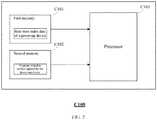
- a block diagram of such a computer device is shown in FIG. 5 .
- the computer device C100 comprises a first memory C101, a second memory C102, and a processor C103.
- the first memory C101 stores the real-time index data of the power-up device that is collected at a certain frequency as described above.
- the second memory C102 stores a program related to service support for the power-up device.
- the processor C103 reads the real-time index data from the first memory C101 and reads the program from the second memory C102, and then executes the program to perform the following steps: a determination step for determining, based on the real-time index data stored in the first memory C101, whether a service level adjustment condition is reached; and a service level adjustment step for intelligently adjusting the service level of the power-up device based on a determination result of the determination step.
- the stored real-time index data is compared individually with a preset safety threshold, and when the comparison result between a certain real-time index data and the safety threshold can reach a preset service level adjustment trigger condition, it is determined whether the stored data starting from the real-time index data within m consecutive data collection cycles meets a preset service level recovery condition, and if the service level recovery condition is not met, it is determined whether the data within the first n data collection cycles of the m data collection cycles meets a preset service level degradation condition.
- the service level of the power-up device is recovered when it is determined in the determination step that the service level recovery condition is met, the service level of the power-up device is degraded when it is determined in the determination step that the service level recovery condition is not met but the service level degradation condition is met, and the service level of the power-up device is maintained as it is when it is determined in the determination step that neither the service level recovery condition nor the service level degradation condition is met.
- the service level adjustment step when it is determined in the determination step that the service level recovery condition is met and the current service level of the power-up device is the highest service level that cannot be further upgraded, the service level of the power-up device is maintained as it is.
- the service level adjustment step when it is determined in the determination step that the service level degradation condition is met and the current service level of the power-up device is the lowest service level that cannot be further degraded, the service of the power-up device is shut down.
- the power-up device may actively collect its own real-time index data and report it to the service support system.
- the service support system may also instruct the power-up device to collect its own real-time index data and report it.
- the processor C103 may also execute the program to perform the following steps: a data collection instruction generation step for generating an instruction for collecting the real-time index data of the power-up device; and a sending step for sending the generated instruction to the power-up device.
- the above examples mainly illustrate the service support system for the power-up device, the service capability intelligent adjustment system, the service support method for the power-up device, the service capability intelligent adjustment method in the service capability intelligent adjustment system, and the computer device according to an embodiment of the invention.
- the service support system for the power-up device the service capability intelligent adjustment system
- the service support method for the power-up device the service capability intelligent adjustment method in the service capability intelligent adjustment system
- the computer device according to an embodiment of the invention.
Landscapes
- Engineering & Computer Science (AREA)
- Computer Networks & Wireless Communication (AREA)
- Signal Processing (AREA)
- Quality & Reliability (AREA)
- Data Mining & Analysis (AREA)
- Management, Administration, Business Operations System, And Electronic Commerce (AREA)
- Mobile Radio Communication Systems (AREA)
- Telephone Function (AREA)
- Power Sources (AREA)
Abstract
Description
- The invention relates to the field of powering up, and more particularly to a service support system for a power-up device, a service capability intelligent adjustment system, a service support method for a power-up device, a service capability intelligent adjustment method in the service capability intelligent adjustment system, and a computer device.
- Historically, when an alarm occurs on a power-up device, the O & M personnel generally mark the power-up device as unavailable after it is discovered, and then shut it down to stop providing services. However, when the power-up device fails and generates an alarm, the power-up device is not completely unable to provide services, but it is likely to provide non-full-load services or a subset of services. Especially during a service demand peak, if the state of these power-up devices is marked as unavailable, it will cause a great waste of resources.
- The invention is implemented to overcome the above-mentioned shortcomings or other shortcomings, and the adopted technical solutions are as follows.
- An embodiment of the invention provides a service support system for a power-up device, the system comprising: a receiving unit configured to receive real-time index data of the power-up device that is collected at a certain frequency from the power-up device; a storage unit configured to store the real-time index data received by the receiving unit; a determination unit configured to determine, based on the real-time index data stored in the storage unit, whether a service level intelligent adjustment condition is reached; and a service level adjustment unit configured to intelligently adjust the service level of the power-up device based on a determination result of the determination unit.
- Further, in the service support system according to an embodiment of the invention, the determination unit is configured to compare the real-time index data stored in the storage unit individually with a preset safety threshold, and determine, when a certain real-time index data meets a preset service level adjustment trigger condition, whether the data stored in the storage unit and starting from the real-time index data within m consecutive data collection cycles meets a preset service level recovery condition, and if the service level recovery condition is not met, determine whether the data within the first n data collection cycles of the m data collection cycles meets a preset service level degradation condition, where m and n both are positive integers and m ≥ n; and the service level adjustment unit is configured to recover the service level of the power-up device when the determination unit determines that the service level recovery condition is met, degrade the service level of the power-up device when the determination unit determines that the service level recovery condition is not met but the service level degradation condition is met, and maintain the service level of the power-up device as it is when the determination unit determines that neither the service level recovery condition nor the service level degradation condition is met.
- Further, in the service support system according to an embodiment of the invention, the service level adjustment unit is configured to maintain, when the determination unit determines that the service level recovery condition is met and the current service level of the power-up device is the highest service level that cannot be further upgraded, the service level of the power-up device as it is.
- Further, in the service support system according to an embodiment of the invention, the service level adjustment unit is configured to shut down, when the determination unit determines that the service level degradation condition is met and the current service level of the power-up device is the lowest service level that cannot be further degraded, the service of the power-up device.
- Further, in the service support system according to an embodiment of the invention, the system further comprises: a display unit configured to display the service level of the power-up device that is obtained after adjustment by the service level adjustment unit.
- Further, in the service support system according to an embodiment of the invention, the system further comprises: a service level notification unit configured to notify the power-up device of the service level obtained after adjustment by the service level adjustment unit.
- Further, in the service support system according to an embodiment of the invention, the system further comprises: a data collection instruction generation unit configured to generate an instruction for collecting the real-time index data of the power-up device; and a sending unit configured to send the generated instruction to the power-up device.
- An embodiment of the invention provides a system for intelligent adjustment of service capabilities, comprising: at least one power-up device, each of which comprising: a data collection unit configured to collect its own real-time index data at a certain frequency; and a sending unit configured to send the real-time index data; and the service support system according to an embodiment of the invention, which interacts with the at least one power-up device in a wired or wireless manner.
- An embodiment of the invention provides a service support method for a power-up device, the method comprising: a receiving step for receiving real-time index data of the power-up device that is collected at a certain frequency from the power-up device; a storage step for storing the real-time index data received in the receiving step; a determination step for determining, based on the stored real-time index data, whether a service level intelligent adjustment condition is reached; and a service level adjustment step for intelligently adjusting the service level of the power-up device based on a determination result of the determination step.
- Further, in the service support method according to an embodiment of the invention, in the determination step, the stored real-time index data is compared individually with a preset safety threshold, and when a certain real-time index data meets a preset service level adjustment trigger condition, it is determined whether the stored data starting from the real-time index data within m consecutive data collection cycles meets a preset service level recovery condition, and if the service level recovery condition is not met, it is determined whether the data within the first n data collection cycles of the m data collection cycles meets a preset service level degradation condition, where m and n both are positive integers and m ≥ n; and in the service level adjustment step, the service level of the power-up device is recovered when it is determined in the determination step that the service level recovery condition is met, the service level of the power-up device is degraded when it is determined in the determination step that the service level recovery condition is not met but the service level degradation condition is met, and the service level of the power-up device is maintained as it is when it is determined in the determination step that neither the service level recovery condition nor the service level degradation condition is met.
- Further, in the service support method according to an embodiment of the invention, in the service level adjustment step, when it is determined in the determination step that the service level recovery condition is met and the current service level of the power-up device is the highest service level that cannot be further upgraded, the service level of the power-up device is maintained as it is.
- Further, in the service support method according to an embodiment of the invention, in the service level adjustment step, when it is determined in the determination step that the service level degradation condition is met and the current service level of the power-up device is the lowest service level that cannot be further degraded, the service of the power-up device is shut down.
- Further, in the service support method according to an embodiment of the invention, the method further comprises: a display step for displaying the service level of the power-up device that is obtained after adjustment in the service level adjustment step.
- Further, in the service support method according to an embodiment of the invention, the method further comprises: a service level notification step for notifying the power-up device of the service level obtained after adjustment in the service level adjustment step.
- Further, in the service support method according to an embodiment of the invention, the method further comprises: a data collection instruction generation step for generating an instruction for collecting the real-time index data of the power-up device; and a sending step for sending the generated instruction to the power-up device.
- An embodiment of the invention provides a method for intelligent adjustment of service capabilities in a service capability intelligent adjustment system. The system comprises at least one power-up device and a service support system for the power-up device. The method comprises: a data collection step for collecting, by each of the at least one power-up device, its own real-time index data at a certain frequency; a sending step for sending, by each of the at least one power-up device, the real-time index data to the service support system; a receiving step for receiving, by the service support system, the real-time index data from each of the at least one power-up device; a storage step for storing for each of the at least one power-up device, by the service support system, the real-time index data received in the receiving step; a determination step for determining for each of the at least one power-up device, by the service support system based on the stored corresponding real-time index data, whether a service level adjustment condition is reached; and a service level adjustment step for intelligently adjusting for each of the at least one power-up device, by the service support system based on a determination result of the determination step, the service level of the power-up device.
- Further, in the method for intelligent adjustment of service capabilities according to an embodiment of the invention, in the determination step, for each of the at least one power-up device, the stored real-time index data is compared individually with a preset safety threshold, and when a certain real-time index data meets a preset service level adjustment trigger condition, it is determined whether the stored data starting from the real-time index data within m consecutive data collection cycles meets a preset service level recovery condition, and if the service level recovery condition is not met, it is determined whether the data within the first n data collection cycles of the m data collection cycles meets a preset service level degradation condition, where m and n both are positive integers and m ≥ n; and in the service level adjustment step, the service level of the power-up device is recovered when it is determined in the determination step that the service level recovery condition is met, the service level of the power-up device is degraded when it is determined in the determination step that the service level recovery condition is not met but the service level degradation condition is met, and the service level of the power-up device is maintained as it is when it is determined in the determination step that neither the service level recovery condition nor the service level degradation condition is met.
- Further, in the service capability intelligent adjustment method according to an embodiment of the invention, in the service level adjustment step, when it is determined in the determination step that the service level recovery condition is met and the current service level of the power-up device is the highest service level that cannot be further upgraded, the service level of the power-up device is maintained as it is.
- Further, in the method for intelligent adjustment of service capabilities according to an embodiment of the invention, in the service level adjustment step, when it is determined in the determination step that the service level degradation condition is met and the current service level of the power-up device is the lowest service level that cannot be further degraded, the service of the power-up device is shut down.
- Further, in the method for intelligent adjustment of service capabilities according to an embodiment of the invention, the method further comprises: a display step for displaying for each of the at least one power-up device, by the service support system, the service level obtained after adjustment in the service level adjustment step.
- Further, in the method for intelligent adjustment of service capabilities according to an embodiment of the invention, the method further comprises: a service level notification step for notifying, by the service support system, each of the at least one power-up device of the service level obtained after adjustment in the service level adjustment step.
- Further, in the method for intelligent adjustment of service capabilities according to an embodiment of the invention, the method further comprises: a data collection instruction generation step for generating, by the service support system, an instruction for collecting the real-time index data of the power-up device; and a sending step for sending, by the service support system, the generated instruction to the power-up device.
- An embodiment of the invention provides a computer device, comprising: a first memory configured to store therein real-time index data of a power-up device that is collected at a certain frequency; a second memory configured to store therein a program related to service support for the power-up device; and a processor configured to execute the program stored in the second memory so as to perform the following steps: a determination step for determining, based on the real-time index data stored in the first memory, whether a service level adjustment condition is reached; and a service level adjustment step for intelligently adjusting the service level of the power-up device based on a determination result of the determination step.
- Further, in the computer device according to an embodiment of the invention, in the determination step, the stored real-time index data is compared individually with a preset safety threshold, and when a certain real-time index data meets a preset service level adjustment trigger condition, it is determined whether the stored data starting from the real-time index data within m consecutive data collection cycles meets a preset service level recovery condition, and if the service level recovery condition is not met, it is determined whether the data within the first n data collection cycles of the m data collection cycles meets a preset service level degradation condition, where m and n both are positive integers and m ≥ n; and in the service level adjustment step, the service level of the power-up device is recovered when it is determined in the determination step that the service level recovery condition is met, the service level of the power-up device is degraded when it is determined in the determination step that the service level recovery condition is not met but the service level degradation condition is met, and the service level of the power-up device is maintained as it is when it is determined in the determination step that neither the service level recovery condition nor the service level degradation condition is met.
- Further, in the computer device according to an embodiment of the invention, in the service level adjustment step, when it is determined in the determination step that the service level recovery condition is met and the current service level of the power-up device is the highest service level that cannot be further upgraded, the service level of the power-up device is maintained as it is.
- Further, in the computer device according to an embodiment of the invention, in the service level adjustment step, when it is determined in the determination step that the service level degradation condition is met and the current service level of the power-up device is the lowest service level that cannot be further degraded, the service of the power-up device is shut down.
- Further, in the computer device according to an embodiment of the invention, the processor further executes the program to perform the following steps: a data collection instruction generation step for generating an instruction for collecting the real-time index data of the power-up device; and a sending step for sending the generated instruction to the power-up device.
- Compared with the prior art, the beneficial effects of the invention are as follows:
- 1) According to the invention, it is possible to dynamically provide a service capability according to the current state of a power-up device while taking into account the availability and service efficiency of the power-up device.
- 2) According to the invention, it is possible to perform step-by-step degrading of the power-up device instead of directly shutting down the service, thereby alleviating service pressure during a service peak.
- 3) According to the invention, the service level of the power-up device can be automatically degraded and recovered without manual intervention.
-
-
FIG. 1 is a block diagram of a system for intelligent adjustment of service capabilities according to an embodiment of the invention; -
FIG. 2 is a specific structural block diagram of a service support system according to an embodiment of the invention; -
FIG. 3 is a schematic flowchart of a method for intelligent adjustment of service capabilities according to an embodiment of the invention; -
FIG. 4 is a detailed flowchart of steps S01 to S04 inFIG. 3 according to an embodiment of the invention; and -
FIG. 5 is a block diagram of a computer device for implementing a service support system according to an embodiment of the invention. - A service support system for a power-up device, a service capability intelligent adjustment system, a service support method for a power-up device, a service capability intelligent adjustment method in the service capability intelligent adjustment system, and a computer device according to the invention will be described in further detail below in combination with the accompanying drawings. It should be noted that the following detailed description of embodiments are exemplary rather than limiting, and are intended to provide a basic understanding of the invention, and are not intended to confirm key or decisive elements of the invention or limit the scope of protection.
-
FIG. 1 is a block diagram of a system for intelligent adjustment of service capabilities according to an embodiment of the invention. Thesystem 1000 for intelligent adjustment of service capabilities shown inFIG. 1 is taken as an example for illustration. Thesystem 1000 for intelligent adjustment of service capabilities is a system for intelligent adjustment of the service capabilities (i.e., service levels) of the power-up device. - It should be noted that the "power-up device" referred to herein includes but is not limited to a battery swap station, a charging station, a mobile battery swap vehicle, a mobile charging vehicle, a charging pile, etc.
- In addition, it should be noted that the "intelligent adjustment of service capabilities (i.e., service level)" mentioned herein includes service level degradation, service level recovery, service level maintenance, etc. The "service level degradation" means that, for example, when monitored real-time index data of the power-up device exceeds or falls below a threshold, or the power-up device generates an alarm or even fails, the service capability (i.e., service level) of the power-up device is strategically reduced to ensure that the power-up device can still provide part of the service instead of directly shutting down the service. The "service level recovery" means that, for example, the service capability (i.e., service level) of the power-up device is strategically recovered until the service capability is completely recovered (i.e., recovered to the highest service level that cannot be further upgraded) when monitored real-time index data of the power-up device shows that the state of the power-up device has improved, or the alarm of the power-up device is gradually eliminated, or the failure of the power-up device is gradually resolved.
- In one example, the service of power-up device can be graded as follows. Assuming that the power-up device can provide up to x batteries with power-up services, service levels of the power-up device can be divided into:
- ⊚ L0 level service: providing power-up services for x batteries;
- ⊚ L1 level service: subtracting power-up services for y batteries, that is, providing power-up services for x-y batteries;
- ⊚ L2 level service: further subtracting power-up services for 2y batteries, that is, providing power-up services for x-3y batteries;
- ... (step by step, power-up services for 2y (q-1) batteries are reduced for each level than the previous level)
- ⊚ Lq level service: further reducing power-up services for 2y (q-1) batteries on the basis of Lq-1 level service, that is, providing power-up services for x-q (q-1) y batteries (q > 1), and if x-q (q-1) y < 0, then providing power-up services for x-(q-1) (q-2) y batteries.
- L0 level is the highest service level mentioned above that cannot be further upgraded, while Lq level is the lowest service level that cannot be further degraded.
- In the case where the current service level of the power-up device is at the L0 level service, the strategy for degrading the service level of the power-up device is divided into an initial service degradation strategy and a secondary service degradation strategy. In the initial service degradation strategy, the service level of the power-up device is degraded from the L0 level service to the L1 level service. In the secondary service degradation strategy, the service level is degraded step by step from the L1 level service to the Lq level service. If further degradation is required at this time, the service of the power-up device is shut down to stop the power-up services for all batteries.
- Alternatively, in the case where the current service level of the power-up device is at the Lq level service, the strategy for recovering the service level of the power-up device is divided into an initial service recovery strategy and a secondary service recovery strategy. In the initial service recovery strategy, the service level of the power-up device is recovered from the Lq level service to the Lq-1 level service. In the secondary service recovery strategy, the service level is recovered step by step from the Lq-1 level service until the L0 level service. If further recovery is required at this time, it can only be maintained at the current L0 level service in view of the maximum number of batteries served by the power-up device.
- As shown in
FIG. 1 , the service capabilityintelligent adjustment system 1000 comprises aservice support system 100 and power-updevices FIG. 1 , it should be appreciated that the number of power-up devices is not limited to two, but may be one or more than three. - In
FIG. 1 , the power-updevices up device 200a is taken as an example for illustration. The power-up device 200a comprises adata collection unit 201a and a sendingunit 202a. - The
data collection unit 201a is configured to collect real-time index data of the power-up device at a certain frequency. It should be noted that the above-mentioned frequency for collecting data can be set by the power-up device itself, or can be preset by the service support system for each power-up device, and the above-mentioned frequency for collecting data can vary with type of the different real-time index data. In addition, it should be noted that the "real-time index data" referred to herein includes but is not limited to the temperature of a battery area of the power-up device, the humidity of the battery area of the power-up device, the power of the power-up device, etc. The monitored real-time index data can be set according to the functional attributes of the power-up device itself and a service target, and a safety threshold for the real-time index data can be preset. In one example, it is assumed that the temperature value k of the battery area of the power-up device is selected as the real-time index data to be monitored, the collection frequency is 1 second/time and the safety threshold is 35 degrees Celsius. - The sending
unit 202a is configured to send the real-time index data collected by thedata collection unit 202a to theservice support system 100. - The
service support system 100 interacts with the power-updevices service support system 100 is illustrated inFIG. 2 . - As shown in
FIG. 2 , theservice support system 100 comprises a receivingunit 101, astorage unit 102, adetermination unit 103, and a servicelevel adjustment unit 104. - Since the
service support system 100 adjusts the service level of each power-up device independently, the power-up device 200a inFIG. 1 is taken as an example for illustration. - The receiving
unit 101 is configured to receive real-time index data of the power-up device 200a that is collected at a certain frequency from the power-up device 200a. - The
storage unit 102 is configured to store the real-time index data of the power-up device 200a received by the receivingunit 101. The storage of the real-time index data can be in the order of collection for subsequent invocation. - The
determination unit 103 is configured to determine, based on the real-time index data of the power-up device 200a stored in thestorage unit 102, whether a service level intelligent adjustment condition is reached. The "service level intelligent adjustment condition" referred to herein includes but is not limited to a service level recovery condition, a service level degradation condition, etc. - Preferably, the
determination unit 103 may compare the real-time index data stored in thestorage unit 102 individually with a preset safety threshold, and determine, when a certain real-time index data meets a preset service level adjustment trigger condition, whether the data stored in thestorage unit 102 and starting from the real-time index data within m consecutive data collection cycles meets a preset service level recovery condition, and if the service level recovery condition is not met, determine whether the data within the first n data collection cycles of the m data collection cycles meets a preset service level degradation condition, where m and n both are positive integers and m ≥ n. - It should be noted that the "service level adjustment trigger condition" mentioned herein may be preset as, for example, the real-time index data (for example, temperature value) is greater than a preset safety threshold (for example, temperature safety threshold) or the real-time index data (for example, power value) is less than a preset safety threshold (for example, power safety threshold), depending on the different types of the real-time index data. In addition, the "service level recovery condition" mentioned herein may also be preset as, for example, the total number of times that the real-time index data (for example, temperature value) does not exceed a safety threshold (for example, temperature safety threshold) within m consecutive data collection cycles reaches a preset probability threshold value β or the total number of times that the real-time index data (for example, power value) exceeds a safety threshold (for example, power safety threshold) within m consecutive data collection cycles reaches a preset probability threshold value β, depending on the different types of the real-time index data. In addition, the "service level degradation condition" mentioned herein may also be preset as, for example, the following conditions (a) (b) (c) and (d) depending on the different types of the real-time index data:
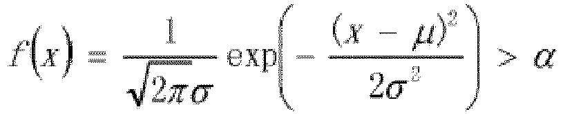
- (a) the probability value of the normal distribution of data k1, k2, k3 ... collected within n consecutive data collection cycles is greater than a preset probability value, which is expressed by the following formula:
- (b) the average value avg (k1, k2, k3 ...) of the data k1, k2, k3 ... collected within the n consecutive data collection cycles exceeds a safety threshold;
- (c) the maximum value max (k1, k2, k3 ...) of the data k1, k2, k3 ... collected within the n consecutive data collection cycles exceeds the safety threshold;
- (d) the minimum value min (k1, k2, k3) of the data k1, k2, k3 ... collected within the n consecutive data collection cycles exceeds the safety threshold.
- In the above example where the temperature value k of a battery area of a power-up device is used as real-time index data, it is assumed that m = 1800, n = 30, µ = 35, σ = 3, α = 0.5, and β = 98%. The determination unit 103 compares the temperature values k1, k2, k3 ... of battery areas of the power-up device stored in the storage unit 102 individually with 35 degrees Celsius, and when the temperature value (for example, ki) of a certain battery area is greater than 35 degrees Celsius (i.e., meets the preset service level adjustment trigger condition), determines for the temperature values ki + 1, ki + 2, ki + 3 ..., stored in the storage unit 102 and starting from the temperature value ki of the battery area within 1800 consecutive data collection cycles whether such a service level recovery condition is met that the number of times not exceeding 35 degrees Celsius accounts for more than 98% of the total number of times, and in the case where the service level recovery condition is not met, determines whether the temperature values collected within the first 30 data collection cycles of the 1800 data collection cycles meets one of the following service level degradation conditions: (I) the numerical average value avg (ki + 1, ki + 2, ki + 3 ...) of temperature values ki + 1, ki + 2, ki + 3 ...... collected within the 30 consecutive data collection cycles exceeds the safety threshold; and (II) the probability value of the normal distribution of temperature values ki + 1, ki + 2, ki + 3 ... collected within 30 consecutive data collection cycles is greater than 0.5.
- The service
level adjustment unit 104 is configured to intelligently adjust the service level of the power-up device 200a based on a determination result of thedetermination unit 103. - Preferably, the service
level adjustment unit 104 recovers the service level of the power-up device 200a when thedetermination unit 103 determines that the above service level recovery condition is met, degrades the service level of the power-up device when thedetermination unit 103 determines that the above service level degradation condition is met, and maintains the service level of the power-up device 200a as it is when thedetermination unit 103 determines that neither the above service level recovery condition nor the above service level degradation condition is met. In particular, when thedetermination unit 103 determines that the above service level recovery condition is met, and the current service level of the power-up device 200a is the highest service level that cannot be further upgraded, the servicelevel adjustment unit 104 maintains the service level of the power-up device 200a as it is. Alternatively, when thedetermination unit 103 determines that the above service level degradation condition is met, and the current service level of the power-up device 200a is the lowest service level that cannot be further degraded, the service of the power-up device 200a is shut down. - In the above example where the temperature value k of the battery area of the power-up device is used as the real-time index data, assuming that the power-up device can provide power-up services for up to 9 batteries and assuming y = 1, the service levels of the power-up device can be divided into:
- ⊚ L0 level service: providing power-up services for 9 batteries;
- ⊚ L1 level service: providing power-up services for 8 batteries;
- ⊚ L2 level service: providing power-up services for 6 batteries;
- ⊚ L3 level service: providing power-up services for 2 batteries.
- L0 level is the highest service level mentioned above that cannot be further upgraded, while L3 level is the lowest service level that cannot be further degraded.
- In the case where the current service level of the power-up device is at the L0 level service, the strategy for degrading the service level of the power-up device is divided into an initial service degradation strategy and a secondary service degradation strategy. In the initial service degradation strategy, the service level of the power-up device is degraded from the L0 level service to the L1 level service. In the secondary service degradation strategy, the service level of the power-up device is degraded step by step to the L2 level service, then to the L3 level service. If further degradation is required at this time, the power-up device is shut down to stop its services.
- Alternatively, in the case where the current service level of the power-up device is at the L3 level service, the strategy for recovering the service level of the power-up device is divided into an initial service recovery strategy and a secondary service recovery strategy. In the initial service recovery strategy, the service level of the power-up device is recovered from the L3 level service to the L2 level service. In the secondary service recovery strategy, the service level is recovered step by step from the L2 level service to the L1 level service, then to the L0 level service. If further recovery is required at this time, it can only be maintained at the current L0 level service in view of the maximum number of batteries served by the power-up device.
- In the above example, when the
determination unit 103 determines that the temperature values ki + 1, ki + 2, ki + 3 ... starting from the temperature value ki of the battery area within 1800 consecutive data collection cycles meet the condition that the number of times not exceeding 35 degrees Celsius accounts for more than 98% of the total number of times, the servicelevel adjustment unit 104 recovers the service level of the power-up device 200a. If the service level of the power-up device 200a is already at the L0 level service at this time, then the power-up device 200a is maintained at the L0 level service. Alternatively, when thedetermination unit 103 determines that the above proportion does not exceed 98% but the temperature values collected within the first 30 data collection cycles of the 1800 data collection cycles meet one of the following service level degradation conditions: (I) the numerical average value avg (ki + 1, ki + 2, ki + 3 ...) of the temperature values ki + 1, ki + 2, ki + 3 ... collected within 30 consecutive data collection cycles exceeds a safety threshold;
(II) the probability value of the normal distribution of the temperature values ki + 1, ki + 2, ki + 3... collected within 30 consecutive data collection cycles is greater than 0.5, the servicelevel adjustment unit 104 degrades the service level of the power-up device 200a. If the service level of the power-up device 200a is already at the L3 level service at this time, the power-up device 200a is shut down to stop the power-up service. Alternatively, when thedetermination unit 103 determines that the above proportion does not exceed 98% but the temperature values collected within the first 30 data collection cycles of the 1800 data collection cycles do not meet any of the above conditions (I) and (II), the servicelevel adjustment unit 104 maintains the service level of the power-up device 200a as it is. - Preferably, the
service support system 100 may further comprise a display unit (not shown) configured to display the service level obtained after adjustment by the servicelevel adjustment unit 104 of the power-up device. - In addition, preferably, the
service support system 100 may further comprise a service level notification unit (not shown) configured to notify the power-up device of the service level obtained after adjustment by the servicelevel adjustment unit 104. - Furthermore, in some embodiments, the power-up
devices service support system 100. However, in some other embodiments, theservice support system 100 may also instruct the power-updevices service support system 100 preferably comprises: a data collection instruction generation unit (not shown) configured to generate instructions for collecting real-time index data of the power-up device; and a sending unit (not shown) configured to send the generated instruction to the power-up device. - Next, the method for intelligent adjustment of service capabilities in the service capability
intelligent adjustment system 1000 shown inFIG. 1 will be described with reference toFIGs. 3 and4 .FIG. 3 is a schematic flowchart of a method for intelligent adjustment of service capabilities according to an embodiment of the invention; andFIG. 4 is a detailed flowchart of steps S01 to S04 inFIG. 3 according to an embodiment of the invention. - As shown in
FIG. 3 , the method for intelligent adjustment of service capabilities comprises a data collection step (S21), a sending step (S22), a receiving step (S01), a storage step (S02), a determination step (S03), and a service level adjustment step (S04). - In the data collection step (S21), each of the at least one power-up device (for example, each of the power-up
devices FIG. 1 ) collects its own real-time index data at a certain frequency. It should be noted that the above-mentioned frequency for collecting data can be set by the power-up device itself, or can be preset by the service support system for each power-up device, and the above-mentioned frequency for collecting data can vary with the type of the different real-time index data. In addition, the description about "real-time index data" is the same as the foregoing, which will not be described in further detail. In one example, it is assumed that the temperature value k of the battery area of the power-up device is selected as the real-time index data to be monitored, the collection frequency is 1 second/time and the safety threshold is 35 degrees Celsius. - In the sending step (S22), each of the at least one power-up device (for example, each of the power-up
devices FIG. 1 ) sends the above real-time index data to theservice support system 100. - In the receiving step (S01), the above real-time index data from each of the at least one power-up device (for example, each of the power-up
devices FIG. 1 ) is received by theservice support system 100. - In the storage step (S02), the
service support system 100 stores, for each of the at least one power-up device (for example, each of the power-updevices FIG. 1 ), the above real-time index data received in the receiving step (S01). The storage of the real-time index data can be in the order of collection for subsequent invocation. - In the determination step (S03), the
service support system 100 determines for each of the at least one power-up device (for example, each of the power-updevices FIG. 1 ), based on the stored corresponding real-time index data, whether a service level intelligent adjustment condition is reached. The description about "service level intelligent adjustment condition" is the same as the foregoing, which will not be described in further detail. - Since the service capability
intelligent adjustment system 1000 adjusts the service level of each power-up device independently, the power-up device 200a inFIG. 1 is taken as an example for illustration. Other power-up devices are similar. - Preferably, in the determination step (S03), the stored real-time index data can be compared individually with a preset safety threshold, and when a certain real-time index data meets a preset service level adjustment trigger condition, it is determined whether the stored data starting from the real-time index data within m consecutive data collection cycles meets a preset service level recovery condition, and if the service level recovery condition is not met, it is determined whether the data within the first n data collection cycles of the m data collection cycles meets a preset service level degradation condition, where m and n both are positive integers and m ≥ n.
- The description about the "service level adjustment trigger condition", "service level recovery condition", and "service level degradation condition" are the same as the foregoing, which will not be described in further detail.
- In the above example where the temperature value k of a battery area of a power-up device is used as real-time index data, it is assumed that m = 1800, n = 30, µ = 35, σ = 3, α = 0.5, and β = 98%. In the determination step (S03), the stored temperature values k1, k2, k3 ... of battery areas of the power-up device are compared individually with 35 degrees Celsius, and when the temperature value (for example, ki) of a certain battery area is greater than 35 degrees Celsius (i.e., meets the preset service level adjustment trigger condition), it is determined for the stored temperature values ki + 1, ki + 2, ki + 3 ... starting from the temperature value ki of the battery area within 1800 consecutive data collection cycles whether such a service level recovery condition is met that the number of times not exceeding 35 degrees Celsius accounts for more than 98% of the total number of times, and in the case where the service level recovery condition is not met, it is determined whether the temperature values collected within the first 30 data collection cycles of the 1800 data collection cycles meets one of the following service level degradation conditions: (I) the numerical average value avg (ki + 1, ki + 2, ki + 3 ...) of temperature values ki + 1, ki + 2, ki + 3 ...... collected within the 30 consecutive data collection cycles exceeds the safety threshold; and (II) the probability value of the normal distribution of temperature values ki + 1, ki + 2, ki + 3 ... collected within 30 consecutive data collection cycles is greater than 0.5.
- In the service level adjustment step (S04), the
service support system 100 intelligently adjusts for each of the at least one power-up device (for example, each of the power-updevices FIG. 1 ), based on the determination result of the determination step (S03), the service level of the power-up device. - Since the service capability
intelligent adjustment system 1000 adjusts the service level of each power-up device independently, the power-up device 200a inFIG. 1 is taken as an example for illustration. Other power-up devices are similar. - Preferably, in the service level adjustment step (S04), the service level of the power-
up device 200a is recovered when it is determined in the determination step (S03) that the above service level recovery condition is met, the service level of the power-up device 200a is degraded when it is determined in the determination step (S03) that the above service level recovery condition is not met but the above service level degradation condition is met, and the service level of the power-up device 200a is maintained as it is when it is determined in the determination step (S03) that neither the above service level recovery condition nor the above service level recovery condition is met. In particular, when it is determined in the determination step (S03) that the above service level recovery condition is met, and the current service level of the power-up device 200a is the highest service level that cannot be further upgraded, in the service level adjustment step (S04), the service level of the power-up device 200a is maintained as it is. Alternatively, when it is determined in the determination step (S03) that the above service level upgradation condition is not met but the above service level degradation condition is met, and the current service level of the power-up device 200a is the lowest service level that cannot be further degraded, in the service level adjustment step (S04), the service of the power-up device 200a is shut down. - In the above example where the temperature value k of the battery area of the power-up device is used as the real-time index data, assuming that the power-up device can provide power-up services for up to 9 batteries and assuming y = 1, the service level of the power-up device can be divided into:
- ⊚ L0 level service: providing power-up services for 9 batteries;
- ⊚ L1 level service: providing power-up services for 8 batteries;
- ⊚ L2 level service: providing power-up services for 6 batteries;
- ⊚ L3 level service: providing power-up services for 2 batteries.
- L0 level is the highest service level mentioned above that cannot be further upgraded, while L3 level is the lowest service level that cannot be further degraded.
- In the case where the current service level of the power-up device is at the L0 level service, the strategy for degrading the service level of the power-up device is divided into an initial service degradation strategy and a secondary service degradation strategy. In the initial service degradation strategy, the service level of the power-up device is degraded from the L0 level service to the L1 level service. In the secondary service degradation strategy, the service level of the power-up device is degraded step by step to the L2 level service, then to the L3 level service. If further degradation is required at this time, the power-up device is shut down to stop its services.
- Alternatively, in the case where the current service level of the power-up device is at the L3 level service, the strategy for recovering the service level of the power-up device is divided into an initial service recovery strategy and a secondary service recovery strategy. In the initial service recovery strategy, the service level of the power-up device is recovered from the L3 level service to the L2 level service. In the secondary service recovery strategy, the service level is recovered step by step from the L2 level service to the L1 level service, then to the L0 level service. If further recovery is required at this time, it can only be maintained at the current L0 level service in view of the maximum number of batteries served by the power-up device.
- In the above example, when it is determined in the determination step (S03) that the temperature values ki + 1, ki + 2, ki + 3 ... starting from the temperature value ki of the battery area within 1800 consecutive data collection cycles meet the condition that the number of times not exceeding 35 degrees Celsius accounts for more than 98% of the total number of times, in the service level adjustment step (S04), the service level of the power-
up device 200a is recovered. If the service level of the power-up device 200a is already at the L0 level service at this time, then the power-up device 200a is maintained at the L0 level service. Alternatively, when it is determined in the determination step (S03) that the above proportion does not exceed 98% but the temperature values collected within the first 30 data collection cycles of the 1800 data collection cycles meet one of the following service level degradation conditions: (I) the numerical average value avg (ki + 1, ki + 2, ki + 3 ...) of the temperature values ki + 1, ki + 2, ki + 3 ... collected within 30 consecutive data collection cycles exceeds a safety threshold; (II) the probability value of the normal distribution of the temperature values ki + 1, ki + 2, ki + 3... collected within 30 consecutive data collection cycles is greater than 0.5, in the service level adjustment step (S04), the service level of the power-up device 200a is degraded. If the service level of the power-up device 200a is already at the L3 level service at this time, the power-up device 200a is shut down to stop the power-up service. Alternatively, when it is determined in the determination step (S03) that the above proportion does not exceed 98% but the temperature values collected within the first 30 data collection cycles of the 1800 data collection cycles do not meet any of the above conditions (I) and (II), in the service level adjustment step (S04), the service level of the power-up device 200a is maintained as it is. - Preferably, the method S1000 for intelligent adjustment of service capabilities may further comprise a display step for displaying, by the
service support system 100, the service level of the power-up device that is obtained after adjustment in the service level adjustment step (S04). - In addition, preferably, the method S1000 for intelligent adjustment of service capabilities may further comprise a service level notification unit for notifying, by the
service support system 100, the power-up device of the service level of the power-up device that is obtained after adjustment in the service level adjustment step (S04). - Furthermore, in some embodiments, the power-up
devices service support system 100. However, in some other embodiments, theservice support system 100 may also instruct the power-updevices service support system 100, an instruction for collecting the real-time index data of the power-up device; and a sending step for sending, by theservice support system 100, the generated instruction to the power-up device. - In the
service support system 100 for a power-up device shown inFIGs. 1 and 2 , the receivingunit 101 may be implemented by a cable or an antenna, which depends on the connection manner (wired or wireless manner) between theservice support system 100 and various power-up devices, while thestorage unit 102, thedetermination unit 103, and the servicelevel adjustment unit 104 may be implemented by a computer device. A block diagram of such a computer device is shown inFIG. 5 . - As shown in
FIG. 5 , the computer device C100 comprises a first memory C101, a second memory C102, and a processor C103. - The first memory C101 stores the real-time index data of the power-up device that is collected at a certain frequency as described above.
- The second memory C102 stores a program related to service support for the power-up device.
- The processor C103 reads the real-time index data from the first memory C101 and reads the program from the second memory C102, and then executes the program to perform the following steps: a determination step for determining, based on the real-time index data stored in the first memory C101, whether a service level adjustment condition is reached; and a service level adjustment step for intelligently adjusting the service level of the power-up device based on a determination result of the determination step.
- Preferably, in the determination step, the stored real-time index data is compared individually with a preset safety threshold, and when the comparison result between a certain real-time index data and the safety threshold can reach a preset service level adjustment trigger condition, it is determined whether the stored data starting from the real-time index data within m consecutive data collection cycles meets a preset service level recovery condition, and if the service level recovery condition is not met, it is determined whether the data within the first n data collection cycles of the m data collection cycles meets a preset service level degradation condition.
- Preferably, in the service level adjustment step, the service level of the power-up device is recovered when it is determined in the determination step that the service level recovery condition is met, the service level of the power-up device is degraded when it is determined in the determination step that the service level recovery condition is not met but the service level degradation condition is met, and the service level of the power-up device is maintained as it is when it is determined in the determination step that neither the service level recovery condition nor the service level degradation condition is met. In particular, in the service level adjustment step, when it is determined in the determination step that the service level recovery condition is met and the current service level of the power-up device is the highest service level that cannot be further upgraded, the service level of the power-up device is maintained as it is. Alternatively, in the service level adjustment step, when it is determined in the determination step that the service level degradation condition is met and the current service level of the power-up device is the lowest service level that cannot be further degraded, the service of the power-up device is shut down.
- Furthermore, as mentioned above, in some embodiments, the power-up device may actively collect its own real-time index data and report it to the service support system. However, in some other embodiments, the service support system may also instruct the power-up device to collect its own real-time index data and report it. In this case, the processor C103 may also execute the program to perform the following steps: a data collection instruction generation step for generating an instruction for collecting the real-time index data of the power-up device; and a sending step for sending the generated instruction to the power-up device.
- The above examples mainly illustrate the service support system for the power-up device, the service capability intelligent adjustment system, the service support method for the power-up device, the service capability intelligent adjustment method in the service capability intelligent adjustment system, and the computer device according to an embodiment of the invention. Although only some specific implementations of the invention are described, a person of ordinary skill in the art should understand that the invention may be implemented in multiple other forms without departing from the essence and scope of the invention. Therefore, the presented examples and implementations are regarded to be schematic rather than restrictive, and without departing from the spirit and scope of the invention that are defined by the appended claims, the invention may cover various changes and replacements.
Claims (27)
- A service support system for a power-up device, characterized by comprising:a receiving unit configured to receive real-time index data of the power-up device that is collected at a certain frequency from the power-up device;a storage unit configured to store the real-time index data received by the receiving unit;a determination unit configured to determine, based on the real-time index data stored in the storage unit, whether a service level intelligent adjustment condition is reached; anda service level adjustment unit configured to intelligently adjust the service level of the power-up device based on a determination result of the determination unit.
- The service support system according to claim 1, characterized in that
the determination unit is configured to compare the real-time index data stored in the storage unit individually with a preset safety threshold, and determine, when a certain real-time index data meets a preset service level adjustment trigger condition, whether the data stored in the storage unit and starting from the real-time index data within m consecutive data collection cycles meets a preset service level recovery condition, and if the service level recovery condition is not met, determine whether the data within the first a data collection cycles of the m data collection cycles meets a preset service level degradation condition, where m and n both are positive integers and m ≥ n; and
the service level adjustment unit is configured to recover the service level of the power-up device when the determination unit determines that the service level recovery condition is met, degrade the service level of the power-up device when the determination unit determines that the service level recovery condition is not met but the service level degradation condition is met, and maintain the service level of the power-up device as it is when the determination unit determines that neither the service level recovery condition nor the service level degradation condition is met. - The service support system according to claim 2, characterized in that
the service level adjustment unit is configured to maintain, when the determination unit determines that the service level recovery condition is met and the current service level of the power-up device is the highest service level that cannot be further upgraded, the service level of the power-up device as it is. - The service support system according to claim 2, characterized in that
the service level adjustment unit is configured to shut down, when the determination unit determines that the service level degradation condition is met and the current service level of the power-up device is the lowest service level that cannot be further degraded, the service of the power-up device. - The service support system according to any one of claims 1 to 4, characterized by further comprising:
a display unit configured to display the service level of the power-up device that is obtained after adjustment by the service level adjustment unit. - The service support system according to any one of claims 1 to 4, characterized by further comprising:
a service level notification unit configured to notify the power-up device of the service level obtained after adjustment by the service level adjustment unit. - The service support system according to any one of claims 1 to 4, characterized by further comprising:a data collection instruction generation unit configured to generate an instruction for collecting the real-time index data of the power-up device; anda sending unit configured to send the generated instruction to the power-up device.
- A system for intelligent adjustment of service capabilities, characterized by comprising:at least one power-up device, each of which comprising: a data collection unit configured to collect its own real-time index data at a certain frequency; and a sending unit configured to send the real-time index data; andthe service support system according to claims 1 to 7, which interacts with the at least one power-up device in a wired or wireless manner.
- A service support method for a power-up device, characterized by comprising:a receiving step for receiving real-time index data of the power-up device that is collected at a certain frequency from the power-up device;a storage step for storing the real-time index data received in the receiving step;a determination step for determining, based on the stored real-time index data, whether a service level intelligent adjustment condition is reached; anda service level adjustment step for intelligently adjusting the service level of the power-up device based on a determination result of the determination step.
- The service support method according to claim 9, characterized in that
in the determination step, the stored real-time index data is compared individually with a preset safety threshold, and when a certain real-time index data meets a preset service level adjustment trigger condition, it is determined whether the stored data starting from the real-time index data within m consecutive data collection cycles meets a preset service level recovery condition, and if the service level recovery condition is not met, it is determined whether the data within the first n data collection cycles of the m data collection cycles meets a preset service level degradation condition, where m and n both are positive integers and m ≥ n; and
in the service level adjustment step, the service level of the power-up device is recovered when it is determined in the determination step that the service level recovery condition is met, the service level of the power-up device is degraded when it is determined in the determination step that the service level recovery condition is not met but the service level degradation condition is met, and the service level of the power-up device is maintained as it is when it is determined in the determination step that neither the service level recovery condition nor the service level degradation condition is met. - The service support method according to claim 10, characterized in that in the service level adjustment step, when it is determined in the determination step that the service level recovery condition is met and the current service level of the power-up device is the highest service level that cannot be further upgraded, the service level of the power-up device is maintained as it is.
- The service support method according to claim 10, characterized in that in the service level adjustment step, when it is determined in the determination step that the service level degradation condition is met and the current service level of the power-up device is the lowest service level that cannot be further degraded, the service of the power-up device is shut down.
- The service support method according to any one of claims 9 to 12, characterized by further comprising:
a display step for displaying the service level of the power-up device that is obtained after adjustment in the service level adjustment step. - The service support method according to any one of claims 9 to 12, characterized by further comprising:
a service level notification step for notifying the power-up device of the service level obtained after adjustment in the service level adjustment step. - The service support method according to any one of claims 9 to 12, characterized by further comprising:a data collection instruction generation step for generating an instruction for collecting the real-time index data of the power-up device; anda sending step for sending the generated instruction to the power-up device.
- A method for intelligent adjustment of service capabilities in a service capability intelligent adjustment system, characterized in that the system comprises at least one power-up device and a service support system for the power-up device, and the method comprises:a data collection step for collecting, by each of the at least one power-up device, its own real-time index data at a certain frequency;a sending step for sending, by each of the at least one power-up device, the real-time index data to the service support system;a receiving step for receiving, by the service support system, the real-time index data from each of the at least one power-up device;a storage step for storing for each of the at least one power-up device, by the service support system, the real-time index data received in the receiving step;a determination step for determining for each of the at least one power-up device, by the service support system based on the stored corresponding real-time index data, whether a service level adjustment condition is reached; anda service level adjustment step for intelligently adjusting for each of the at least one power-up device, by the service support system based on a determination result of the determination step, the service level of the power-up device.
- The method for intelligent adjustment of service capabilities according to claim 16, characterized in that
in the determination step, for each of the at least one power-up device, the stored real-time index data is compared individually with a preset safety threshold, and when a certain real-time index data meets a preset service level adjustment trigger condition, it is determined whether the stored data starting from the real-time index data within m consecutive data collection cycles meets a preset service level recovery condition, and if the service level recovery condition is not met, it is determined whether the data within the first a data collection cycles of the m data collection cycles meets a preset service level degradation condition, where m and n both are positive integers and m ≥ n; and
in the service level adjustment step, the service level of the power-up device is recovered when it is determined in the determination step that the service level recovery condition is met, the service level of the power-up device is degraded when it is determined in the determination step that the service level recovery condition is not met but the service level degradation condition is met, and the service level of the power-up device is maintained as it is when it is determined in the determination step that neither the service level recovery condition nor the service level degradation condition is met. - The method for intelligent adjustment of service capabilities according to claim 17, characterized in that
in the service level adjustment step, when it is determined in the determination step that the service level recovery condition is met and the current service level of the power-up device is the highest service level that cannot be further upgraded, the service level of the power-up device is maintained as it is. - The method for intelligent adjustment of service capabilities according to claim 17, characterized in that
in the service level adjustment step, when it is determined in the determination step that the service level degradation condition is met and the current service level of the power-up device is the lowest service level that cannot be further degraded, the service of the power-up device is shut down. - The method for intelligent adjustment of service capabilities according to any one of claims 16 to 19, characterized by further comprising:
a display step for displaying for each of the at least one power-up device, by the service support system, the service level obtained after adjustment in the service level adjustment step. - The method for intelligent adjustment of service capabilities according to any one of claims 16 to 19, characterized by further comprising:
a service level notification step for notifying, by the service support system, each of the at least one power-up device of the service level obtained after adjustment in the service level adjustment step. - The method for intelligent adjustment of service capabilities according to any one of claims 16 to 19, characterized by further comprising:a data collection instruction generation step for generating, by the service support system, an instruction for collecting the real-time index data of the power-up device; anda sending step for sending, by the service support system, the generated instruction to the power-up device.
- A computer device, characterized by comprising:a first memory configured to store therein real-time index data of a power-up device that is collected at a certain frequency;a second memory configured to store therein a program related to service support for the power-up device; anda processor configured to execute the program stored in the second memory so as to perform the following steps:a determination step for determining, based on the real-time index data stored in the first memory, whether a service level adjustment condition is reached; anda service level adjustment step for intelligently adjusting the service level of the power-up device based on a determination result of the determination step.
- The computer device according to claim 23, characterized in that
in the determination step, the stored real-time index data is compared individually with a preset safety threshold, and when a certain real-time index data meets a preset service level adjustment trigger condition, it is determined whether the stored data starting from the real-time index data within m consecutive data collection cycles meets a preset service level recovery condition, and if the service level recovery condition is not met, it is determined whether the data within the first n data collection cycles of the m data collection cycles meets a preset service level degradation condition, where m and n both are positive integers and m ≥ n; and
in the service level adjustment step, the service level of the power-up device is recovered when it is determined in the determination step that the service level recovery condition is met, the service level of the power-up device is degraded when it is determined in the determination step that the service level recovery condition is not met but the service level degradation condition is met, and the service level of the power-up device is maintained as it is when it is determined in the determination step that neither the service level recovery condition nor the service level degradation condition is met. - The computer device according to claim 24, characterized in that
in the service level adjustment step, when it is determined in the determination step that the service level recovery condition is met and the current service level of the power-up device is the highest service level that cannot be further upgraded, the service level of the power-up device is maintained as it is. - The computer device according to claim 24, characterized in that
in the service level adjustment step, when it is determined in the determination step that the service level degradation condition is met and the current service level of the power-up device is the lowest service level that cannot be further degraded, the service of the power-up device is shut down. - The computer device according to any one of claims 23 to 26, characterized in that the processor further executes the program to perform the following steps:a data collection instruction generation step for generating an instruction for collecting the real-time index data of the power-up device; anda sending step for sending the generated instruction to the power-up device.
Applications Claiming Priority (2)
| Application Number | Priority Date | Filing Date | Title |
|---|---|---|---|
| CN201711047935.5A CN107864054B (en) | 2017-10-31 | 2017-10-31 | Service support system and method, service capability intelligent adjustment system and method, computer equipment |
| PCT/CN2018/092333 WO2019085516A1 (en) | 2017-10-31 | 2018-06-22 | Service support system and method, intelligent service ability adjustment system and method, and computer device |
Publications (3)
| Publication Number | Publication Date |
|---|---|
| EP3706366A1 true EP3706366A1 (en) | 2020-09-09 |
| EP3706366A4 EP3706366A4 (en) | 2021-07-14 |
| EP3706366B1 EP3706366B1 (en) | 2025-09-10 |
Family
ID=61697110
Family Applications (1)
| Application Number | Title | Priority Date | Filing Date |
|---|---|---|---|
| EP18873086.5A Active EP3706366B1 (en) | 2017-10-31 | 2018-06-22 | Service support system and method, intelligent service ability adjustment system and method, and computer device |
Country Status (3)
| Country | Link |
|---|---|
| EP (1) | EP3706366B1 (en) |
| CN (1) | CN107864054B (en) |
| WO (1) | WO2019085516A1 (en) |
Families Citing this family (1)
| Publication number | Priority date | Publication date | Assignee | Title |
|---|---|---|---|---|
| CN107864054B (en) * | 2017-10-31 | 2021-08-24 | 蔚来(安徽)控股有限公司 | Service support system and method, service capability intelligent adjustment system and method, computer equipment |
Family Cites Families (8)
| Publication number | Priority date | Publication date | Assignee | Title |
|---|---|---|---|---|
| CN100388677C (en) * | 2004-09-27 | 2008-05-14 | 华为技术有限公司 | Method for Dynamically Modifying Business Service Level |
| US8866444B2 (en) * | 2010-06-08 | 2014-10-21 | Tesla Motors, Inc. | Methodology for charging batteries safely |
| US8872480B2 (en) * | 2011-12-01 | 2014-10-28 | Siemens Industry, Inc. | Current monitoring and limiting apparatus, system and method for electric vehicle supply equipment |
| CN104660436B (en) * | 2013-11-25 | 2018-05-11 | 中国电信股份有限公司 | service level management method and system |
| CN104869003A (en) * | 2014-02-25 | 2015-08-26 | 华为技术有限公司 | Power supply device and method |
| CN104578297B (en) * | 2015-01-08 | 2017-02-22 | 漳州科华技术有限责任公司 | Modular photovoltaic charger dormancy control device and method |
| CN104993554B (en) * | 2015-08-05 | 2018-08-07 | 南京捷泰电力设备有限公司 | A kind of charging device of electric automobile and its operation method |
| CN107864054B (en) * | 2017-10-31 | 2021-08-24 | 蔚来(安徽)控股有限公司 | Service support system and method, service capability intelligent adjustment system and method, computer equipment |
-
2017
- 2017-10-31 CN CN201711047935.5A patent/CN107864054B/en active Active
-
2018
- 2018-06-22 EP EP18873086.5A patent/EP3706366B1/en active Active
- 2018-06-22 WO PCT/CN2018/092333 patent/WO2019085516A1/en not_active Ceased
Also Published As
| Publication number | Publication date |
|---|---|
| CN107864054A (en) | 2018-03-30 |
| WO2019085516A1 (en) | 2019-05-09 |
| EP3706366B1 (en) | 2025-09-10 |
| EP3706366A4 (en) | 2021-07-14 |
| CN107864054B (en) | 2021-08-24 |
Similar Documents
| Publication | Publication Date | Title |
|---|---|---|
| Ding et al. | Distributed resilient finite-time secondary control for heterogeneous battery energy storage systems under denial-of-service attacks | |
| US9351170B2 (en) | Renewable energy base station and coverage adjustment method therefor, and wireless cellular system | |
| US10379166B2 (en) | Cabinet and battery management and monitoring system for use with uninterruptible power supplies | |
| EP3796509A1 (en) | Battery system, and method for detecting state of health of battery | |
| CN104638718A (en) | Intelligent management system and method of electric vehicle battery | |
| US20170040839A1 (en) | Flexible control architecture for microgrid resiliency | |
| EP3754807A1 (en) | Substation direct-current power supply system and power storage method | |
| EP2934038A1 (en) | Cell outage detection and compensation method and device | |
| US20180159327A1 (en) | Method for controlling an electric power distribution micro-grid | |
| EP3783965A1 (en) | Base station device energy-saving method and device | |
| EP3706366A1 (en) | Service support system and method, intelligent service ability adjustment system and method, and computer device | |
| EP4350927A1 (en) | Power reserve method and related device | |
| CN118539542A (en) | Energy storage system dynamic switching control method and energy storage system | |
| CN117791813A (en) | Wireless charging protection method, system and medium for robot | |
| CN106707194B (en) | Rechargeable battery detection method and electronic equipment | |
| CN109149698A (en) | Dual multiple power levels based on frequency modulation energy-storage system limit guard method | |
| US11706659B2 (en) | Method for operating intelligent electronic device and an intelligent electronic device | |
| EP3312970A1 (en) | Communication device, power management device, and power management method | |
| CN116802377A (en) | blind device | |
| US20240179632A1 (en) | Power consumption control method, apparatus, and system for electric device | |
| AU2024201157B2 (en) | Control device and control method | |
| CN211266509U (en) | Battery charging and discharging protection device and battery | |
| CN108199352B (en) | Battery protecting method and device | |
| JP2015231316A (en) | Power storage system | |
| CN103179598B (en) | A kind of dead zone of cell removing method and device |
Legal Events
| Date | Code | Title | Description |
|---|---|---|---|
| STAA | Information on the status of an ep patent application or granted ep patent |
Free format text: STATUS: THE INTERNATIONAL PUBLICATION HAS BEEN MADE |
|
| PUAI | Public reference made under article 153(3) epc to a published international application that has entered the european phase |
Free format text: ORIGINAL CODE: 0009012 |
|
| STAA | Information on the status of an ep patent application or granted ep patent |
Free format text: STATUS: REQUEST FOR EXAMINATION WAS MADE |
|
| 17P | Request for examination filed |
Effective date: 20200529 |
|
| AK | Designated contracting states |
Kind code of ref document: A1 Designated state(s): AL AT BE BG CH CY CZ DE DK EE ES FI FR GB GR HR HU IE IS IT LI LT LU LV MC MK MT NL NO PL PT RO RS SE SI SK SM TR |
|
| AX | Request for extension of the european patent |
Extension state: BA ME |
|
| RAP1 | Party data changed (applicant data changed or rights of an application transferred) |
Owner name: NIO (ANHUI) HOLDING CO., LTD. |
|
| RIN1 | Information on inventor provided before grant (corrected) |
Inventor name: FU, QIANG |
|
| DAV | Request for validation of the european patent (deleted) | ||
| DAX | Request for extension of the european patent (deleted) | ||
| A4 | Supplementary search report drawn up and despatched |
Effective date: 20210616 |
|
| RIC1 | Information provided on ipc code assigned before grant |
Ipc: H04L 12/24 20060101AFI20210610BHEP Ipc: B60L 53/60 20190101ALI20210610BHEP |
|
| STAA | Information on the status of an ep patent application or granted ep patent |
Free format text: STATUS: EXAMINATION IS IN PROGRESS |
|
| 17Q | First examination report despatched |
Effective date: 20240102 |
|
| REG | Reference to a national code |
Ref legal event code: R079 Ipc: H04L0041500900 Ref country code: DE Ref legal event code: R079 Ref document number: 602018085533 Country of ref document: DE Free format text: PREVIOUS MAIN CLASS: H04L0012240000 Ipc: H04L0041500900 |
|
| GRAP | Despatch of communication of intention to grant a patent |
Free format text: ORIGINAL CODE: EPIDOSNIGR1 |
|
| STAA | Information on the status of an ep patent application or granted ep patent |
Free format text: STATUS: GRANT OF PATENT IS INTENDED |
|
| INTG | Intention to grant announced |
Effective date: 20250415 |
|
| RIC1 | Information provided on ipc code assigned before grant |
Ipc: B60L 53/60 20190101ALI20250407BHEP Ipc: H04L 41/5009 20220101AFI20250407BHEP |
|
| GRAS | Grant fee paid |
Free format text: ORIGINAL CODE: EPIDOSNIGR3 |
|
| GRAA | (expected) grant |
Free format text: ORIGINAL CODE: 0009210 |
|
| STAA | Information on the status of an ep patent application or granted ep patent |
Free format text: STATUS: THE PATENT HAS BEEN GRANTED |
|
| AK | Designated contracting states |
Kind code of ref document: B1 Designated state(s): AL AT BE BG CH CY CZ DE DK EE ES FI FR GB GR HR HU IE IS IT LI LT LU LV MC MK MT NL NO PL PT RO RS SE SI SK SM TR |
|
| RAP3 | Party data changed (applicant data changed or rights of an application transferred) |
Owner name: NIO (ANHUI) HOLDING CO., LTD. |
|
| REG | Reference to a national code |
Ref country code: GB Ref legal event code: FG4D |
|
| REG | Reference to a national code |
Ref country code: CH Ref legal event code: EP |
|
| REG | Reference to a national code |
Ref country code: DE Ref legal event code: R096 Ref document number: 602018085533 Country of ref document: DE |
|
| REG | Reference to a national code |
Ref country code: IE Ref legal event code: FG4D |
|
| PG25 | Lapsed in a contracting state [announced via postgrant information from national office to epo] |
Ref country code: NO Free format text: LAPSE BECAUSE OF FAILURE TO SUBMIT A TRANSLATION OF THE DESCRIPTION OR TO PAY THE FEE WITHIN THE PRESCRIBED TIME-LIMIT Effective date: 20251210 |
|
| REG | Reference to a national code |
Ref country code: LT Ref legal event code: MG9D |
|
| PG25 | Lapsed in a contracting state [announced via postgrant information from national office to epo] |
Ref country code: FI Free format text: LAPSE BECAUSE OF FAILURE TO SUBMIT A TRANSLATION OF THE DESCRIPTION OR TO PAY THE FEE WITHIN THE PRESCRIBED TIME-LIMIT Effective date: 20250910 |
|
| REG | Reference to a national code |
Ref country code: NL Ref legal event code: MP Effective date: 20250910 |
|
| PG25 | Lapsed in a contracting state [announced via postgrant information from national office to epo] |
Ref country code: HR Free format text: LAPSE BECAUSE OF FAILURE TO SUBMIT A TRANSLATION OF THE DESCRIPTION OR TO PAY THE FEE WITHIN THE PRESCRIBED TIME-LIMIT Effective date: 20250910 |
|
| PG25 | Lapsed in a contracting state [announced via postgrant information from national office to epo] |
Ref country code: GR Free format text: LAPSE BECAUSE OF FAILURE TO SUBMIT A TRANSLATION OF THE DESCRIPTION OR TO PAY THE FEE WITHIN THE PRESCRIBED TIME-LIMIT Effective date: 20251211 |
|
| PG25 | Lapsed in a contracting state [announced via postgrant information from national office to epo] |
Ref country code: SE Free format text: LAPSE BECAUSE OF FAILURE TO SUBMIT A TRANSLATION OF THE DESCRIPTION OR TO PAY THE FEE WITHIN THE PRESCRIBED TIME-LIMIT Effective date: 20250910 |
|
| PG25 | Lapsed in a contracting state [announced via postgrant information from national office to epo] |
Ref country code: LV Free format text: LAPSE BECAUSE OF FAILURE TO SUBMIT A TRANSLATION OF THE DESCRIPTION OR TO PAY THE FEE WITHIN THE PRESCRIBED TIME-LIMIT Effective date: 20250910 |
|
| PG25 | Lapsed in a contracting state [announced via postgrant information from national office to epo] |
Ref country code: BG Free format text: LAPSE BECAUSE OF FAILURE TO SUBMIT A TRANSLATION OF THE DESCRIPTION OR TO PAY THE FEE WITHIN THE PRESCRIBED TIME-LIMIT Effective date: 20250910 Ref country code: PL Free format text: LAPSE BECAUSE OF FAILURE TO SUBMIT A TRANSLATION OF THE DESCRIPTION OR TO PAY THE FEE WITHIN THE PRESCRIBED TIME-LIMIT Effective date: 20250910 |
|
| PG25 | Lapsed in a contracting state [announced via postgrant information from national office to epo] |
Ref country code: RS Free format text: LAPSE BECAUSE OF FAILURE TO SUBMIT A TRANSLATION OF THE DESCRIPTION OR TO PAY THE FEE WITHIN THE PRESCRIBED TIME-LIMIT Effective date: 20251210 |
|
| PG25 | Lapsed in a contracting state [announced via postgrant information from national office to epo] |
Ref country code: ES Free format text: LAPSE BECAUSE OF FAILURE TO SUBMIT A TRANSLATION OF THE DESCRIPTION OR TO PAY THE FEE WITHIN THE PRESCRIBED TIME-LIMIT Effective date: 20250910 |
|
| REG | Reference to a national code |
Ref country code: AT Ref legal event code: MK05 Ref document number: 1837128 Country of ref document: AT Kind code of ref document: T Effective date: 20250910 |
|
| PG25 | Lapsed in a contracting state [announced via postgrant information from national office to epo] |
Ref country code: NL Free format text: LAPSE BECAUSE OF FAILURE TO SUBMIT A TRANSLATION OF THE DESCRIPTION OR TO PAY THE FEE WITHIN THE PRESCRIBED TIME-LIMIT Effective date: 20250910 |
|
| PG25 | Lapsed in a contracting state [announced via postgrant information from national office to epo] |
Ref country code: SM Free format text: LAPSE BECAUSE OF FAILURE TO SUBMIT A TRANSLATION OF THE DESCRIPTION OR TO PAY THE FEE WITHIN THE PRESCRIBED TIME-LIMIT Effective date: 20250910 |
|
| PG25 | Lapsed in a contracting state [announced via postgrant information from national office to epo] |
Ref country code: AT Free format text: LAPSE BECAUSE OF FAILURE TO SUBMIT A TRANSLATION OF THE DESCRIPTION OR TO PAY THE FEE WITHIN THE PRESCRIBED TIME-LIMIT Effective date: 20250910 |
|
| PG25 | Lapsed in a contracting state [announced via postgrant information from national office to epo] |
Ref country code: IT Free format text: LAPSE BECAUSE OF FAILURE TO SUBMIT A TRANSLATION OF THE DESCRIPTION OR TO PAY THE FEE WITHIN THE PRESCRIBED TIME-LIMIT Effective date: 20250910 |
|
| PG25 | Lapsed in a contracting state [announced via postgrant information from national office to epo] |
Ref country code: IS Free format text: LAPSE BECAUSE OF FAILURE TO SUBMIT A TRANSLATION OF THE DESCRIPTION OR TO PAY THE FEE WITHIN THE PRESCRIBED TIME-LIMIT Effective date: 20260110 |
|
| PG25 | Lapsed in a contracting state [announced via postgrant information from national office to epo] |
Ref country code: CZ Free format text: LAPSE BECAUSE OF FAILURE TO SUBMIT A TRANSLATION OF THE DESCRIPTION OR TO PAY THE FEE WITHIN THE PRESCRIBED TIME-LIMIT Effective date: 20250910 Ref country code: PT Free format text: LAPSE BECAUSE OF FAILURE TO SUBMIT A TRANSLATION OF THE DESCRIPTION OR TO PAY THE FEE WITHIN THE PRESCRIBED TIME-LIMIT Effective date: 20260112 |
|
| PG25 | Lapsed in a contracting state [announced via postgrant information from national office to epo] |
Ref country code: SK Free format text: LAPSE BECAUSE OF FAILURE TO SUBMIT A TRANSLATION OF THE DESCRIPTION OR TO PAY THE FEE WITHIN THE PRESCRIBED TIME-LIMIT Effective date: 20250910 Ref country code: EE Free format text: LAPSE BECAUSE OF FAILURE TO SUBMIT A TRANSLATION OF THE DESCRIPTION OR TO PAY THE FEE WITHIN THE PRESCRIBED TIME-LIMIT Effective date: 20250910 |