EP3706349B1 - Anzeige der rückkopfflung hybrider automatischer wiederholungsanfragen und rückkopplungsverfahren, vorrichtung und basisstation - Google Patents
Anzeige der rückkopfflung hybrider automatischer wiederholungsanfragen und rückkopplungsverfahren, vorrichtung und basisstation Download PDFInfo
- Publication number
- EP3706349B1 EP3706349B1 EP17931883.7A EP17931883A EP3706349B1 EP 3706349 B1 EP3706349 B1 EP 3706349B1 EP 17931883 A EP17931883 A EP 17931883A EP 3706349 B1 EP3706349 B1 EP 3706349B1
- Authority
- EP
- European Patent Office
- Prior art keywords
- harq feedback
- downlink data
- timing relationships
- uplink harq
- timing
- Prior art date
- Legal status (The legal status is an assumption and is not a legal conclusion. Google has not performed a legal analysis and makes no representation as to the accuracy of the status listed.)
- Active
Links
Images




Classifications
-
- H—ELECTRICITY
- H04—ELECTRIC COMMUNICATION TECHNIQUE
- H04L—TRANSMISSION OF DIGITAL INFORMATION, e.g. TELEGRAPHIC COMMUNICATION
- H04L1/00—Arrangements for detecting or preventing errors in the information received
- H04L1/12—Arrangements for detecting or preventing errors in the information received by using return channel
- H04L1/16—Arrangements for detecting or preventing errors in the information received by using return channel in which the return channel carries supervisory signals, e.g. repetition request signals
- H04L1/18—Automatic repetition systems, e.g. Van Duuren systems
- H04L1/1812—Hybrid protocols; Hybrid automatic repeat request [HARQ]
- H04L1/1819—Hybrid protocols; Hybrid automatic repeat request [HARQ] with retransmission of additional or different redundancy
-
- H—ELECTRICITY
- H04—ELECTRIC COMMUNICATION TECHNIQUE
- H04L—TRANSMISSION OF DIGITAL INFORMATION, e.g. TELEGRAPHIC COMMUNICATION
- H04L1/00—Arrangements for detecting or preventing errors in the information received
- H04L1/12—Arrangements for detecting or preventing errors in the information received by using return channel
- H04L1/16—Arrangements for detecting or preventing errors in the information received by using return channel in which the return channel carries supervisory signals, e.g. repetition request signals
- H04L1/18—Automatic repetition systems, e.g. Van Duuren systems
- H04L1/1867—Arrangements specially adapted for the transmitter end
- H04L1/1896—ARQ related signaling
-
- H—ELECTRICITY
- H04—ELECTRIC COMMUNICATION TECHNIQUE
- H04L—TRANSMISSION OF DIGITAL INFORMATION, e.g. TELEGRAPHIC COMMUNICATION
- H04L5/00—Arrangements affording multiple use of the transmission path
- H04L5/003—Arrangements for allocating sub-channels of the transmission path
- H04L5/0053—Allocation of signalling, i.e. of overhead other than pilot signals
- H04L5/0055—Physical resource allocation for ACK/NACK
-
- H—ELECTRICITY
- H04—ELECTRIC COMMUNICATION TECHNIQUE
- H04L—TRANSMISSION OF DIGITAL INFORMATION, e.g. TELEGRAPHIC COMMUNICATION
- H04L1/00—Arrangements for detecting or preventing errors in the information received
- H04L1/12—Arrangements for detecting or preventing errors in the information received by using return channel
- H04L1/16—Arrangements for detecting or preventing errors in the information received by using return channel in which the return channel carries supervisory signals, e.g. repetition request signals
- H04L1/1607—Details of the supervisory signal
-
- H—ELECTRICITY
- H04—ELECTRIC COMMUNICATION TECHNIQUE
- H04L—TRANSMISSION OF DIGITAL INFORMATION, e.g. TELEGRAPHIC COMMUNICATION
- H04L1/00—Arrangements for detecting or preventing errors in the information received
- H04L1/12—Arrangements for detecting or preventing errors in the information received by using return channel
- H04L1/16—Arrangements for detecting or preventing errors in the information received by using return channel in which the return channel carries supervisory signals, e.g. repetition request signals
- H04L1/18—Automatic repetition systems, e.g. Van Duuren systems
- H04L1/1829—Arrangements specially adapted for the receiver end
- H04L1/1854—Scheduling and prioritising arrangements
-
- H—ELECTRICITY
- H04—ELECTRIC COMMUNICATION TECHNIQUE
- H04L—TRANSMISSION OF DIGITAL INFORMATION, e.g. TELEGRAPHIC COMMUNICATION
- H04L5/00—Arrangements affording multiple use of the transmission path
-
- H—ELECTRICITY
- H04—ELECTRIC COMMUNICATION TECHNIQUE
- H04L—TRANSMISSION OF DIGITAL INFORMATION, e.g. TELEGRAPHIC COMMUNICATION
- H04L5/00—Arrangements affording multiple use of the transmission path
- H04L5/0091—Signalling for the administration of the divided path, e.g. signalling of configuration information
- H04L5/0094—Indication of how sub-channels of the path are allocated
-
- H—ELECTRICITY
- H04—ELECTRIC COMMUNICATION TECHNIQUE
- H04W—WIRELESS COMMUNICATION NETWORKS
- H04W72/00—Local resource management
- H04W72/04—Wireless resource allocation
-
- H—ELECTRICITY
- H04—ELECTRIC COMMUNICATION TECHNIQUE
- H04W—WIRELESS COMMUNICATION NETWORKS
- H04W72/00—Local resource management
- H04W72/04—Wireless resource allocation
- H04W72/044—Wireless resource allocation based on the type of the allocated resource
- H04W72/0446—Resources in time domain, e.g. slots or frames
-
- H—ELECTRICITY
- H04—ELECTRIC COMMUNICATION TECHNIQUE
- H04W—WIRELESS COMMUNICATION NETWORKS
- H04W72/00—Local resource management
- H04W72/20—Control channels or signalling for resource management
- H04W72/23—Control channels or signalling for resource management in the downlink direction of a wireless link, i.e. towards a terminal
-
- H—ELECTRICITY
- H04—ELECTRIC COMMUNICATION TECHNIQUE
- H04W—WIRELESS COMMUNICATION NETWORKS
- H04W76/00—Connection management
- H04W76/20—Manipulation of established connections
- H04W76/27—Transitions between radio resource control [RRC] states
-
- H—ELECTRICITY
- H04—ELECTRIC COMMUNICATION TECHNIQUE
- H04W—WIRELESS COMMUNICATION NETWORKS
- H04W8/00—Network data management
- H04W8/22—Processing or transfer of terminal data, e.g. status or physical capabilities
- H04W8/24—Transfer of terminal data
-
- H—ELECTRICITY
- H04—ELECTRIC COMMUNICATION TECHNIQUE
- H04W—WIRELESS COMMUNICATION NETWORKS
- H04W80/00—Wireless network protocols or protocol adaptations to wireless operation
- H04W80/02—Data link layer protocols
-
- H—ELECTRICITY
- H04—ELECTRIC COMMUNICATION TECHNIQUE
- H04L—TRANSMISSION OF DIGITAL INFORMATION, e.g. TELEGRAPHIC COMMUNICATION
- H04L1/00—Arrangements for detecting or preventing errors in the information received
- H04L1/12—Arrangements for detecting or preventing errors in the information received by using return channel
- H04L1/16—Arrangements for detecting or preventing errors in the information received by using return channel in which the return channel carries supervisory signals, e.g. repetition request signals
- H04L1/18—Automatic repetition systems, e.g. Van Duuren systems
- H04L1/1812—Hybrid protocols; Hybrid automatic repeat request [HARQ]
Definitions
- the present disclosure generally relates to the technical field of communication, and more particularly, to a method and device for Hybrid Automatic Repeat reQuest (HARQ) feedback indication, and a method and device for HARQ feedback.
- HARQ Hybrid Automatic Repeat reQuest
- eMBB enhanced Mobile Broad Band
- URLLC Ultra Reliable Low Latency Communication
- mMTC massive Machine Type Communication
- a time varying characteristic and multipath fading of a wireless channel may bring influence to signal transmission, resulting in a data transmission failure.
- a HARQ mechanism is introduced into a conventional wireless communication system, and a sending side determines whether a data packet that has been sent is required to be resent according to a feedback of a receiving side about whether data is correctly received.
- LTE Long-Term Evolution
- ACK Acknowledgement
- NACK Negative Acknowledgement
- ms milliseconds
- HARQ feedback of a downlink data packet is synchronous. That is, there is a fixed timing relationship between transmission of the downlink data packet and uplink ACK or NACK feedback of the downlink data packet.
- HARQ feedback of an uplink data packet may be synchronous or asynchronous.
- the UE may have a higher processing capability.
- the UE may give an ACK or NACK feedback faster for received data to reduce a data transmission delay. This is important to some services with relatively high delay requirements such as a URLLC service.
- a conventional HARQ timing feedback manner is no more applicable to such a scenario.
- WO 2017/184049 A1 discloses a delaying transmission depending on transmission type and UE processing capabilities.
- HUAWEI HISILICON "HARQ timing, multiplexing, and bundling", 3GPP DRAFT; R1-1715408, MOBILE COMPETENCE CENTRE; 650, ROUTE DES LUCIOLES; F-06921, XP051338876 , discloses the HARQ processing time, the HAQR process number, the signaling design for HARQ timing indication, the principles of HARQ-ACK multiplexing and HARQ-ACK bundling.
- HUAWEI HISILICON "discussion on timing relations and signaling of HARQ timing for NR", 3GPP DRAFT; R1-1611218, MOBILE COMPETENCE CENTRE; 650, ROUTE DES LUCIOLES; F-06921, XP051175199 , discloses timing relations and signaling of HARQ timing for NR.
- the present disclosure discloses a method and device for HARQ feedback indication, and a method and device for HARQ feedback, to support dynamical HARQ feedback of UE.
- a method for HARQ feedback indication for applying to a base station which is set forth in claim 1.
- the uplink HARQ feedback indication information may be carried in an information field of the DCI, and a bit length of the information field may be a fixed value or may be determined based on the number of timing relationships included in the set of first timing relationships.
- the uplink HARQ feedback indication information in response to the UE does not support dynamic HARQ feedback, may be a fixed value, the fixed value may be in the set of first timing relationships, and the fixed value may be preset by a present system or configured by the base station.
- the uplink HARQ feedback indication information may be carried in an information field of the DCI, and a bit length of the information field may be a fixed value or may be determined based on the number of timing relationships included in the set of first timing relationships.
- the uplink HARQ feedback indication information in response to the UE does not support dynamic HARQ feedback, may be a fixed value, the fixed value may be in the set of first timing relationships, and the fixed value may be preset by a present system or configured by the base station.
- a device for HARQ feedback indication for applying to a base station which is set forth in claim 7.
- a device for HARQ feedback for applying to UE which is set forth in claim 8.
- the uplink HARQ feedback indication information is generated for the present downlink data and the present downlink data and the DCI carrying the uplink HARQ feedback indication information are sent to the UE, to enable the UE to acquire the timing relationship between the time-domain unit where the present downlink data is located and the time-domain unit for uplink HARQ feedback of the present downlink data according to the uplink HARQ feedback indication information and the prestored set of first timing relationships, and send the uplink HARQ feedback information for the present downlink data according to the acquired timing relationship, so that the UE may implement dynamic HARQ feedback.
- the uplink HARQ feedback indication information is obtained by parsing the received DCI, the timing relationship between the time-domain unit where the present downlink data is located and the time-domain unit for uplink HARQ feedback of the present downlink data is acquired according to the uplink HARQ feedback indication information and the prestored set of first timing relationships, and the uplink HARQ feedback information for the present downlink data is sent according to the acquired timing relationship, so that dynamic HARQ feedback is implemented.
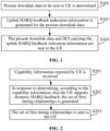
- FIG. 1 is a flowchart illustrating a method for HARQ feedback indication, according to an embodiment of the present disclosure. The embodiment is described from a base station side. As illustrated in FIG. 1 , the HARQ feedback indication method includes the following steps.
- present downlink data is determined to be sent to UE.
- uplink HARQ feedback indication information for the present downlink data is generated, a timing relationship indicated by the uplink HARQ feedback indication information being included in a set of first timing relationships between time-domain units where downlink data for the UE are located and time-domain units for uplink HARQ feedback of the downlink data.
- a base station generates the uplink HARQ feedback indication information for the present downlink data
- the uplink HARQ feedback indication information may be carried in an information field of DCI, and a bit length of the information field may be a fixed value and may also be determined based on the number of timing relationships included in the set of first timing relationships. For example, if the set of first timing relationships includes four timing relationships, the length of the information field is 2 bit.
- the uplink HARQ feedback indication information in response to the UE supports dynamic HARQ feedback, for different downlink data, may be different numerical values.
- the uplink HARQ feedback indication information is a fixed value, the fixed value is a plurality of fixed values in the set of first timing relationships, and may be preset by a present system or configured by the base station.
- the present downlink data and DCI carrying the uplink HARQ feedback indication information are sent to the UE.
- the base station after generating the uplink HARQ feedback indication information for the present downlink data, sends the present downlink data and the DCI carrying the uplink HARQ feedback indication information to the UE; and the UE, after receiving the DCI, acquires the timing relationship between the time-domain unit where the present downlink data is located and the time-domain unit for uplink HARQ feedback of the present downlink data according to the uplink HARQ feedback indication information obtained by parsing and the prestored set of first timing relationships, and sends uplink HARQ feedback information for the present downlink data.
- the uplink HARQ feedback indication information is generated for the present downlink data and the present downlink data and the DCI carrying the uplink HARQ feedback indication information are sent to the UE, to enable the UE to acquire the timing relationship between the time-domain unit where the present downlink data is located and the time-domain unit for uplink HARQ feedback of the present downlink data according to the uplink HARQ feedback indication information and the prestored set of first timing relationships, and send the uplink HARQ feedback information of the present downlink data according to the acquired timing relationship, so that the UE may implement dynamic HARQ feedback.
- S201 and S202 are executed before S 102.
- the set of first timing relationships is sent to the UE.
- the set of first timing relationships is generated, and the set of first timing relationships is sent to the UE, so that a condition is provided for generation of the uplink HARQ feedback indication information and sending of the uplink HARQ feedback information.
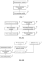
- FIG. 3 is a flowchart illustrating another method for HARQ feedback indication, according to an embodiment of the present disclosure. As illustrated in FIG. 3 , based on the embodiment illustrated in FIG. 1 , the method for HARQ feedback indication may further include the following steps.
- a set of second timing relationships between time-domain units where downlink data supported by a present system are located and time-domain units for uplink HARQ feedback of the downlink data is predefined, or the set of second timing relationships is notified to the UE through signaling.
- a generation rule for the set of first timing relationships is generated.
- S301 to S303 are executed before S102.
- the set of first timing relationships is a subset of the set of second timing relationships.
- the generation rule for the set of first timing relationships is generated and the generation rule for the set of first timing relationships is sent to the UE, to enable the UE to generate the set of first timing relationships according to the generation rule and the set of second timing relationships, so that a condition is provided for generation of the uplink HARQ feedback indication information and the uplink HARQ feedback information.
- present downlink data and DCI carrying uplink HARQ feedback indication information for the present downlink data are received from a base station, a timing relationship indicated by the uplink HARQ feedback indication information being included in a set of first timing relationships between time-domain units where downlink data for UE are located and time-domain units for uplink HARQ feedback of the downlink data.
- the uplink HARQ feedback indication information is obtained by parsing the DCI.
- a timing relationship between a time-domain unit where the present downlink data is located and a time-domain unit for uplink HARQ feedback of the present downlink data is acquired according to the uplink HARQ feedback indication information and the prestored set of first timing relationships.
- Table 11 Set of First Timing Relationships Entry Timing relationship 00 1 symbol 01 2 symbols 10 4 symbols 11 10 symbols
- the uplink HARQ feedback indication information is 01, it may be acquired according to the uplink HARQ feedback indication information and the set of first timing relationships illustrated in Table 1 that the timing relationship between the time-domain unit where the present downlink data is located and the time-domain unit for uplink HARQ feedback of the present downlink data is two symbols.
- Table 11 is only an example of the set of first timing relationships and, during a practical application, another format, for example, a format illustrated in Table 12, may also be adopted for the set of first timing relationships.
- Table 12 Set of First Timing Relationships Entry Timing relationship 1 1 symbol 2 2 symbols 3 4 symbols 4 10 symbols
- a corresponding relationship between the contents of the entries and the contents indicated by the information field may be predefined, or the base station may also notify the corresponding relationship between the contents of the entries and the contents indicated by the information field to the UE through signaling.
- the corresponding relationship may be that contents 00, 01, 10 and 11 indicated by the information field correspond to the entries 1, 2, 3 and 4 in Table 12 respectively.
- uplink HARQ feedback information for the present downlink data is sent according to the acquired timing relationship.
- the UE sends the uplink HARQ feedback information for the present downlink data on symbol 5.
- the uplink HARQ feedback indication information is obtained by parsing the received DCI, the timing relationship between the time-domain unit where the present downlink data is located and the time-domain unit for uplink HARQ feedback of the present downlink data is acquired according to the uplink HARQ feedback indication information and the prestored set of first timing relationships, and the uplink HARQ feedback information for the present downlink data is sent according to the acquired timing relationship, so that dynamic HARQ feedback is implemented.
- FIG. 5 is a flowchart illustrating another method for HARQ feedback, according to an embodiment not being part of the present invention. As illustrated in FIG. 5 , the HARQ feedback method may further include the following steps.
- the first timing relationship set sent by the base station according to the capability information is received and stored.
- FIG. 6 is a flowchart illustrating another method for HARQ feedback, according to an embodiment of the present disclosure. As illustrated in FIG. 6 , the method for HARQ feedback may further include the following steps.
- a set of second timing relationships which is predefined, or is received from the base station via signaling, between time-domain units where downlink data supported by a present system are located and time-domain units for uplink HARQ feedback of the downlink data is obtained.
- the capability information of the UE is reported to the base station.
- the set of first timing relationships is generated according to the generation rule and the set of second timing relationships.
- the set of first timing relationships is a subset of the set of second timing relationships.
- the set of second timing relationships is obtained, the generation rule, which is sent by the base station according to the capability information reported by the UE, for the set of first timing relationships is received, and the set of first timing relationships is generated according to the generation rule and the set of second timing relationships, so that a condition is provided for the UE to acquire the timing relationship between the time-domain unit where the present downlink data is located and the time-domain unit for uplink HARQ feedback of the present downlink data, and a condition is further provided for sending of the uplink HARQ feedback information.
- FIG. 7 is a block diagram of a device for HARQ feedback indication, according to an embodiment.
- the device is positioned in a base station. As illustrated in FIG. 7 , the device includes a determination module 71, a first generation module 72 and a first sending module 73.
- the determination module 71 is configured to determine present downlink data to be sent to UE.
- the first generation module 72 is configured to generate uplink HARQ feedback indication information for the present downlink data determined by the determination module 71, a timing relationship indicated by the uplink HARQ feedback indication information being included in a set of first timing relationships between time-domain units where downlink data for the UE are located and time-domain units for uplink HARQ feedback of the downlink data.
- the base station generates the uplink HARQ feedback indication information for the present downlink data
- the uplink HARQ feedback indication information may be carried in an information field of DCI, and a bit length of the information field may be a fixed value and may also be determined based on the number of timing relationships included in the set of first timing relationships. For example, if the set of first timing relationships includes four timing relationships, the length of the information field is 2 bit.
- the uplink HARQ feedback indication information in response to the UE supports dynamic HARQ feedback, for different downlink data, may be different numerical values.
- the uplink HARQ feedback indication information is a fixed value, the fixed value is a plurality of fixed values in the set of first timing relationships, and may be preset by a present system or configured by the base station.
- the first sending module 73 is configured to send the present downlink data and DCI carrying the uplink HARQ feedback indication information generated by the first generation module 72 to the UE.
- the base station after generating the uplink HARQ feedback indication information for the present downlink data, sends the present downlink data and the DCI carrying the uplink HARQ feedback indication information to the UE; and the UE, after receiving the DCI, acquires the timing relationship between the time-domain unit where the present downlink data is located and the time-domain unit for uplink HARQ feedback of the present downlink data according to the uplink HARQ feedback indication information obtained by parsing and the prestored set of first timing relationships, and sends uplink HARQ feedback information for the present downlink data.
- the uplink HARQ feedback indication information is generated for the present downlink data, and the present downlink data and the DCI carrying the uplink HARQ feedback indication information are sent to the UE, to enable the UE to acquire the timing relationship between the time-domain unit where the present downlink data is located and the time-domain unit for uplink HARQ feedback of the present downlink data according to the uplink HARQ feedback indication information and the prestored set of first timing relationships, and send the uplink HARQ feedback information of the present downlink data according to the acquired timing relationship, so that the UE may implement dynamic HARQ feedback.
- FIG. 8A is a block diagram of another device for HARQ feedback indication, according to an embodiment not being part of the invention. As illustrated in FIG. 8A , based on the embodiment illustrated in FIG. 7 , the device may further include a first receiving module 74, a first determination generation module 75 and a second sending module 76.
- the first receiving module 74 is configured to receive capability information reported by the UE.
- the first determination generation module 75 is configured to, in response to determining, according to the capability information received by the first receiving module 74, that the UE supports dynamic HARQ feedback, generate the set of first timing relationships.
- the second sending module 76 is configured to send the set of first timing relationships generated by the first determination generation module 75 to the UE.
- the set of first timing relationships is generated, and the set of first timing relationships is sent to the UE, so that a condition is provided for generation of the uplink HARQ feedback indication information and sending of the uplink HARQ feedback information.
- FIG. 8B is a block diagram of another device for HARQ feedback indication, according to an embodiment. As illustrated in FIG. 8B , based on the embodiment illustrated in FIG. 7 , the device further includes a definition and notification module 77, a second receiving module 78, a second determination generation module 79 and a third sending module 80.
- the definition and notification module 77 is configured to predefine a set of second timing relationships between time-domain units where downlink data supported by a present system are located and time-domain units for uplink HARQ feedback of the downlink data, or notify the set of second timing relationships to the UE through signaling.
- the signaling includes RRC signaling, a MAC CE or physical-layer signaling.
- the second receiving module 78 is configured to receive the capability information reported by the UE.
- the second determination generation module 79 is configured to, in response to determining, according to the capability information received by the second receiving module 78, that the UE supports dynamic HARQ feedback, generate a generation rule for the set of first timing relationships.
- the third sending module 80 is configured to send the generation rule generated by the second determination generation module 79 to the UE for generating, by the UE, the set of first timing relationships according to the generation rule and the set of second timing relationships defined or notified by the definition and notification module 77.
- the set of first timing relationships is a subset of the set of second timing relationships.
- the generation rule for the set of first timing relationships is generated and the generation rule for the set of first timing relationships is sent to the UE, to enable the UE to generate the set of first timing relationships according to the generation rule and the set of second timing relationships, so that a condition is provided for generation of the uplink HARQ feedback indication information and the uplink HARQ feedback information.
- the information receiving module 91 is configured to receive present downlink data and DCI carrying uplink HARQ feedback indication information for the present downlink data from a base station, a timing relationship indicated by the uplink HARQ feedback indication information being included in a set of first timing relationships between time-domain units where downlink data for the UE are located and time-domain units for uplink HARQ feedback of the downlink data.
- the uplink HARQ feedback indication information may be carried in an information field of the DCI, and a bit length of the information field may be a fixed value and may also be determined based on the number of timing relationships included in the set of first timing relationships. For example, if the set of first timing relationships includes four timing relationships, the length of the information field is 2 bit.
- the parsing module 92 is configured to obtain the uplink HARQ feedback indication information by parsing the DCI received by the information receiving module 91.
- the acquisition module 93 is configured to acquire a timing relationship between a time-domain unit where the present downlink data is located and a time-domain unit for uplink HARQ feedback of the present downlink data according to the uplink HARQ feedback indication information obtained by the parsing module 92 and the prestored set of first timing relationships.
- the uplink HARQ feedback indication information is 01, it may be acquired according to the uplink HARQ feedback indication information and the set of first timing relationships illustrated in Table 1 that the timing relationship between the time-domain unit where the present downlink data is located and the time-domain unit for uplink HARQ feedback of the present downlink data is two symbols.
- Table 11 is only an example of the set of first timing relationships and, during a practical application, another format, for example, a format illustrated in Table 12, may also be adopted for the set of first timing relationships.
- a corresponding relationship between the contents of the entries and the contents indicated by the information field may be predefined, or the base station may also notify the corresponding relationship between the contents of the entries and the contents indicated by the information field to the UE through signaling.
- the corresponding relationship may be that contents 00, 01, 10 and 11 indicated by the information field correspond to the entries 1, 2, 3 and 4 in Table 12 respectively.
- the sending module 94 is configured to send uplink HARQ feedback information for the present downlink data according to the timing relationship acquired by the acquisition module 93.
- the UE sends the uplink HARQ feedback information for the present downlink data on symbol 5.
- the uplink HARQ feedback indication information is obtained by parsing the received DCI, the timing relationship between the time-domain unit where the present downlink data is located and the time-domain unit for uplink HARQ feedback of the present downlink data is acquired according to the uplink HARQ feedback indication information and the prestored set of first timing relationships, and the uplink HARQ feedback information for the present downlink data is sent according to the acquired timing relationship, so that dynamic HARQ feedback is implemented.
- the first reporting module 95 is configured to report capability information of the UE to the base station.
- the receiving and storing module 96 is configured to receive and store the set of first timing relationships sent by the base station according to the capability information reported by the first reporting module 95.
- the capability information of the UE is reported to the base station, and the base station, in response to determining according to the capability information that the UE supports dynamic HARQ feedback, generates the set of first timing relationships and sends the set of first timing relationships to the UE, so that a condition is provided for the UE to acquire the timing relationship between the time-domain unit where the present downlink data is located and the time-domain unit for uplink HARQ feedback of the present downlink data, and a condition is further provided for sending of the uplink HARQ feedback information.
- FIG. 10B is a block diagram of another device for HARQ feedback, according to an embodiment. As illustrated in FIG. 10B , based on the embodiment illustrated in FIG. 9 , the device further includes an obtaining module 97, a second reporting module 98, a generation rule receiving module 99, a second generation module 100 and a storing module 110.
- the obtaining module 97 is configured to obtain a set of second timing relationships, which is predefined, or is received from the base station via signaling, between time-domain units where downlink data supported by a present system are located and time-domain units for uplink HARQ feedback of the downlink data.
- the signaling includes RRC signaling, a MAC CE or physical-layer signaling.
- the second reporting module 98 is configured to report the capability information of the UE to the base station.
- the generation rule receiving module 99 is configured to receive a generation rule, which is sent by the base station according to the capability information reported by the second reporting module 98, for the set of first timing relationships.
- the second generation module 100 is configured to generate the set of first timing relationships according to the generation rule received by the generation rule receiving module 99 and the set of second timing relationships obtained by the obtaining module 97.
- the storing module 110 is configured to store the set of first timing relationships generated by the second generation module 100.
- the set of first timing relationships is a subset of the set of second timing relationships.
- the set of second timing relationships is obtained, the generation rule, which is sent by the base station according to the capability information reported by the UE, for the set of first timing relationships is received, and the set of first timing relationships is generated according to the generation rule and the set of second timing relationships, so that a condition is provided for the UE to acquire the timing relationship between the time-domain unit where the present downlink data is located and the time-domain unit for uplink HARQ feedback of the present downlink data, and a condition is further provided for sending of the uplink HARQ feedback information.
- FIG. 11 is a block diagram of a device applied to HARQ feedback indication, according to the invention.
- the device 1100 may be provided as a base station.
- the device 1100 includes a processing component 1122, a wireless transmitting/receiving component 1124, an antenna component 1126 and a wireless interface-specific signal processing part, and the processing component 1122 may further include one or more processors.
- One processor of the processing component 1122 may be configured to:
- a non-transitory computer-readable storage medium including an instruction, and the instruction may be executed by the processing component 1122 of the device 1100 to implement the method for HARQ feedback indication.
- the non-transitory computer-readable storage medium may be a Read-Only Memory (ROM), a Random-Access Memory (RAM), a Compact Disc Read-Only Memory (CD-ROM), a magnetic tape, a floppy disc, an optical data storage device and the like.
- FIG. 12 is a block diagram of a device applied to HARQ feedback, according to the invention.
- the device 1200 may be UE such as a mobile phone, a computer, a digital broadcast terminal, a messaging device, a gaming console, a tablet, a medical device, exercise equipment and a personal digital assistant.
- the device 1200 may include one or more of the following components: a processing component 1202, a memory 1204, a power component 1206, a multimedia component 1208, an audio component 1210, an Input/Output (I/O) interface 1212, a sensor component 1214, and a communication component 1216.
- a processing component 1202 a memory 1204, a power component 1206, a multimedia component 1208, an audio component 1210, an Input/Output (I/O) interface 1212, a sensor component 1214, and a communication component 1216.
- the processing component 1202 typically controls overall operations of the device 1200, such as the operations associated with display, telephone calls, data communications, camera operations, and recording operations.
- the processing component 1202 may include one or more processors 1220 to execute instructions to perform all or part of the steps in the abovementioned method.
- the processing component 1202 may include one or more modules which facilitate interaction between the processing component 1202 and the other components.
- the processing component 1202 may include a multimedia module to facilitate interaction between the multimedia component 1208 and the processing component 1202.
- One processor 1220 in the processing component 1202 may be configured to:
- the memory 1204 is configured to store various types of data to support the operation of the device 1200. Examples of such data include instructions for any applications or methods operated on the device 1200, contact data, phonebook data, messages, pictures, video, etc.
- the memory 1204 may be implemented by any type of volatile or non-volatile memory devices, or a combination thereof, such as a Static Random Access Memory (SRAM), an Electrically Erasable Programmable Read-Only Memory (EEPROM), an Erasable Programmable Read-Only Memory (EPROM), a Programmable Read-Only Memory (PROM), a ROM, a magnetic memory, a flash memory, and a magnetic or optical disk.
- SRAM Static Random Access Memory
- EEPROM Electrically Erasable Programmable Read-Only Memory
- EPROM Erasable Programmable Read-Only Memory
- PROM Programmable Read-Only Memory
- the power component 1206 provides power for various components of the device 1200.
- the power component 1206 may include a power management system, one or more power supplies, and other components associated with generation, management and distribution of power for the device 1200.
- the multimedia component 1208 includes a screen providing an output interface between the device 1200 and a user.
- the screen may include a Liquid Crystal Display (LCD) and a Touch Panel (TP). If the screen includes the TP, the screen may be implemented as a touch screen to receive an input signal from the user.
- the TP includes one or more touch sensors to sense touches, swipes and gestures on the TP. The touch sensors may not only sense a boundary of a touch or swipe action but also detect a duration and pressure associated with the touch or swipe action.
- the multimedia component 1208 includes a front camera and/or a rear camera.
- the front camera and/or the rear camera may receive external multimedia data when the device 1200 is in an operation mode, such as a photographing mode or a video mode.
- an operation mode such as a photographing mode or a video mode.
- Each of the front camera and the rear camera may be a fixed optical lens system or have focusing and optical zooming capabilities.
- the audio component 1210 is configured to output and/or input an audio signal.
- the audio component 1210 includes a Microphone (MIC), and the MIC is configured to receive an external audio signal when the device 1200 is in the operation mode, such as a call mode, a recording mode and a voice recognition mode.
- the received audio signal may further be stored in the memory 1204 or sent through the communication component 1216.
- the audio component 1210 further includes a speaker configured to output the audio signal.
- the I/O interface 1212 provides an interface between the processing component 1202 and a peripheral interface module, and the peripheral interface module may be a keyboard, a click wheel, a button and the like.
- the button may include, but not limited to: a home button, a volume button, a starting button and a locking button.
- the sensor component 1214 includes one or more sensors configured to provide status assessment in various aspects for the device 1200. For instance, the sensor component 1214 may detect an on/off status of the device 1200 and relative positioning of components, such as a display and small keyboard of the device 1200, and the sensor component 1214 may further detect a change in a position of the device 1200 or a component of the device 1200, presence or absence of contact between the user and the device 1200, orientation or acceleration/deceleration of the device 1200 and a change in temperature of the device 1200.
- the sensor component 1214 may include a proximity sensor configured to detect presence of an object nearby without any physical contact.
- the sensor component 1214 may also include a light sensor, such as a Complementary Metal Oxide Semiconductor (CMOS) or Charge Coupled Device (CCD) image sensor, configured for use in an imaging application.
- CMOS Complementary Metal Oxide Semiconductor
- CCD Charge Coupled Device
- the sensor component 1214 may also include an acceleration sensor, a gyroscope sensor, a magnetic sensor, a pressure sensor or a temperature sensor.
- the communication component 1216 is configured to facilitate wired or wireless communication between the device 1200 and another device.
- the device 1200 may access a communication-standard-based wireless network, such as a Wireless Fidelity (Wi-Fi) network, a 2nd-Generation (2G) or 3rd-Generation (3G) network or a combination thereof.
- Wi-Fi Wireless Fidelity
- 2G 2nd-Generation
- 3G 3rd-Generation
- the communication component 1216 receives a broadcast signal or broadcast associated information from an external broadcast management system through a broadcast channel.
- the communication component 1216 further includes a Near Field Communication (NFC) module to facilitate short-range communication.
- NFC Near Field Communication
- the NFC module may be implemented based on a Radio Frequency Identification (RFID) technology, an Infrared Data Association (IrDA) technology, an Ultra-Wide Band (UWB) technology, a Bluetooth (BT) technology and another technology.
- RFID Radio Frequency Identification
- IrDA Infrared Data Association
- UWB Ultra-Wide Band
- BT Bluetooth
- the device 1200 may be implemented by one or more Application Specific Integrated Circuits (ASICs), Digital Signal Processors (DSPs), Digital Signal Processing Devices (DSPDs), Programmable Logic Devices (PLDs), Field Programmable Gate Arrays (FPGAs), controllers, micro-controllers, microprocessors or other electronic components, and is configured to execute the HARQ feedback method.
- ASICs Application Specific Integrated Circuits
- DSPs Digital Signal Processors
- DSPDs Digital Signal Processing Devices
- PLDs Programmable Logic Devices
- FPGAs Field Programmable Gate Arrays
- controllers micro-controllers, microprocessors or other electronic components, and is configured to execute the HARQ feedback method.
- a non-transitory computer-readable storage medium including an instruction such as the memory 1204 including an instruction, and the instruction may be executed by the processor 1220 of the device 1200 to implement the abovementioned method.
- the non-transitory computer-readable storage medium may be a ROM, a RAM, a CD-ROM, a magnetic tape, a floppy disc, an optical data storage device and the like.
- the device embodiments substantially correspond to the method embodiments, and thus related parts refer to part of descriptions of the method embodiments.
- the device embodiment described above is only schematic, units described as separate parts therein may or may not be physically separated, and parts displayed as units may or may not be physical units, and namely may be located in the same place or may also be distributed to multiple network units. Part or all of the modules therein may be selected according to a practical requirement to achieve the purpose of the solutions of the embodiments. Those of ordinary skill in the art may understand and implement without creative work.
Landscapes
- Engineering & Computer Science (AREA)
- Signal Processing (AREA)
- Computer Networks & Wireless Communication (AREA)
- Databases & Information Systems (AREA)
- Mobile Radio Communication Systems (AREA)
Claims (8)
- Verfahren für Hybrid-Automatic-Repeat-reQuest-Rückmeldungsangabe, HARQ-Rückmeldungsangabe, zur Anwendung auf eine Basisstation, wobei das Verfahren umfasst:Bestimmen (S101) aktueller Downlink-Daten, die an ein Benutzergerät, UE, gesendet werden sollen;Erzeugen (S102) von Uplink-HARQ-Rückmeldungsangabeinformationen für die aktuellen Downlink-Daten, wobei eine durch die Uplink-HARQ-Rückmeldungsangabeinformationen angegebene Zeitbeziehung in einem Satz erster Zeitbeziehungen zwischen Zeitbereichseinheiten, in denen sich Downlink-Daten für das UE befinden, und Zeitbereichseinheiten für Uplink-HARQ-Rückmeldung der Downlink-Daten umfasst sind; undSenden (S103) der aktuellen Downlink-Daten und Downlink-Steuerinformationen, DCI, die die Uplink-HARQ-Rückmeldungsangabeinformationen tragen, an das UE;dadurch gekennzeichnet, dass das Verfahren weiter umfasst:Empfangen (S302) von dem UE gemeldeten Kapazitätsinformationen;als Reaktion auf Bestimmen, gemäß den Kapazitätsinformationen, dass das UE dynamische HARQ-Rückmeldung unterstützt, Erzeugen (S3O3) einer Erzeugungsregel, wobei die Erzeugungsregel zum Erzeugen des Satzes erster Zeitbeziehungen unter Verwendung eines vordefinierten Satzes zweiter Zeitbeziehungen zwischen Zeitbereichseinheiten, in denen sich von einem aktuellen System unterstützte Downlink-Daten befinden, und den Zeitbereichseinheiten für die Uplink-HARQ-Rückmeldung der Downlink-Daten verwendet wird, und der Satz erster Zeitbeziehungen ein Teilsatz des Satzes zweiter Zeitbeziehungen ist; undSenden (S304) der Erzeugungsregel an das UE zum Erzeugen des Satzes erster Zeitbeziehungen gemäß der Erzeugungsregel und dem Satz zweiter Zeitbeziehungen an dem UE.
- Verfahren nach Anspruch 1, wobei die Uplink-HARQ-Rückmeldungsangabeinformationen in einem Informationsfeld der DCI getragen werden, und eine Bitlänge des Informationsfelds ein fester Wert ist oder basierend auf einer Anzahl von Zeitbeziehungen, die in dem Satz erster Zeitbeziehungen umfasst sind, bestimmt wird.
- Verfahren nach Anspruch 1, wobei als Reaktion darauf, dass das UE keine dynamische HARQ-Rückmeldung unterstützt, die Uplink-HARQ-Rückmeldungsangabeinformationen ein fester Wert sind, der feste Wert aus einer Vielzahl von festen Werten in dem Satz erster Zeitbeziehungen ausgewählt wird und durch das aktuelle System voreingestellt oder durch die Basisstation konfiguriert wird.
- Verfahren für hybride automatische Wiederholungsanforderungs-Rückmeldung, HARQ-Rückmeldung, zur Anwendung auf ein Benutzergerät, UE, wobei das Verfahren umfasst:Empfangen (S401) aktueller Downlink-Daten und von Downlink-Steuerinformationen, DCI, die Uplink-HARQ-Rückmeldungsangabeinformationen für die aktuellen Downlink-Daten tragen, von einer Basisstation, wobei eine durch die Uplink-HARQ-Rückmeldungsangabeinformationen angegebene Zeitbeziehung in einem Satz erster Zeitbeziehungen zwischen Zeitbereichseinheiten, in denen sich Downlink-Daten für das UE befinden, und Zeitbereichseinheiten für Uplink-HARQ-Rückmeldung der Downlink-Daten umfasst ist;Erhalten (S402) der Uplink-HARQ-Rückmeldungsangabeinformationen durch Parsen der DCI;Erheben (S403) einer Zeitbeziehung zwischen einer Zeitbereichseinheit, in der sich die aktuellen Downlink-Daten befinden, und einer Zeitbereichseinheit für Uplink-HARQ-Rückmeldung der aktuellen Downlink-Daten gemäß den Uplink-HARQ-Rückmeldungsangabeinformationen und einem vorgespeicherten Satz erster Zeitbeziehungen; undSenden (S404) von Uplink-HARQ-Rückmeldungsinformationen für die aktuellen Downlink-Daten gemäß der erhobenen Zeitbeziehung;dadurch gekennzeichnet, dass das Verfahren weiter umfasst:Melden (S6O2) von Kapazitätsinformationen des UE an die Basisstation;Empfangen (S6O3) einer Erzeugungsregel, die von der Basisstation gemäß den Kapazitätsinformationen gesendet wird, zum Erzeugen des Satzes erster Zeitbeziehungen unter Verwendung eines vordefinierten Satzes zweiter Zeitbeziehungen zwischen Zeitbereichseinheiten, in denen sich von einem aktuellen System unterstützte Downlink-Daten befinden, und Zeitbereichseinheiten für Uplink-HARQ-Rückmeldung der Downlink-Daten, und wobei der Satz erster Zeitbeziehungen ein Teilsatz des Satzes zweiter Zeitbeziehungen ist;Erzeugen (S6O4) des Satzes erster Zeitbeziehungen gemäß der Erzeugungsregel und dem Satz zweiter Zeitbeziehungen; undSpeichern (S6O5) des Satzes erster Zeitbeziehungen.
- Verfahren nach Anspruch 4, wobei die Uplink-HARQ-Rückmeldungsangabeinformationen in einem Informationsfeld der DCI getragen werden und eine Bitlänge des Informationsfelds ein fester Wert ist oder basierend auf einer Anzahl von Zeitbeziehungen, die in dem Satz erster Zeitbeziehungen umfasst sind, bestimmt wird.
- Verfahren nach Anspruch 4, wobei als Reaktion darauf, dass das UE keine dynamische HARQ-Rückmeldung unterstützt, die Uplink-HARQ-Rückmeldungsangabeinformationen ein fester Wert sind, der feste Wert aus einer Vielzahl von festen Werten in dem Satz erster Zeitbeziehungen ausgewählt wird, wobei der feste Wert durch das aktuelle System voreingestellt oder durch die Basisstation konfiguriert wird.
- Vorrichtung für Hybrid-Automatic-Repeat-reQuest-Rückmeldungsangabe, HARQ-Rückmeldungsangabe, zur Anwendung auf eine Basisstation und wobei die Vorrichtung umfasst:ein Bestimmungsmodul (71), das dazu konfiguriert ist, aktuelle Downlink-Daten zu bestimmen, die an das Benutzergerät (UE) gesendet werden sollen;ein erstes Erzeugungsmodul (72), das dazu konfiguriert ist, Uplink-HARQ-Rückmeldungsangabeinformationen für die aktuellen Downlink-Daten zu erzeugen, die von dem Bestimmungsmodul (71) bestimmt werden, wobei eine durch die Uplink-HARQ-Rückmeldungsangabeinformationen angegebene Zeitbeziehung in einem Satz erster Zeitbeziehungen zwischen Zeitbereichseinheiten, in denen sich Downlink-Daten für das UE befinden, und Zeitbereichseinheiten für Uplink-HARQ-Rückmeldung der Downlink-Daten umfasst sind; undein erstes Sendemodul (73), das dazu konfiguriert ist, die aktuellen Downlink-Daten und Downlink-Steuerinformationen, (DCI), die die von dem ersten Erzeugungsmodul (72) erzeugten Uplink-HARQ-Rückmeldungsangabeinformationen tragen, an das UE zu senden;dadurch gekennzeichnet, dass die Vorrichtung weiter Folgendes umfasst:ein zweites Empfangsmodul (78), das dazu konfiguriert ist, von dem UE gemeldete Kapazitätsinformationen zu empfangen;ein zweites Bestimmungserzeugungsmodul (79), das dazu konfiguriert ist, als Reaktion auf Bestimmen, gemäß den von dem zweiten Empfangsmodul empfangenen Kapazitätsinformationen, dass das UE dynamische HARQ-Rückmeldung unterstützt, eine Erzeugungsregel zu erzeugen, wobei die Erzeugungsregel zum Erzeugen des Satzes erster Zeitbeziehungen unter Verwendung eines vordefinierten Satzes zweiter Zeitbeziehungen zwischen Zeitbereichseinheiten, in denen sich von einem aktuellen System unterstützte Downlink-Daten befinden, und den Zeitbereichseinheiten für die Uplink-HARQ-Rückmeldung der Downlink-Daten verwendet wird, und der Satz erster Zeitbeziehungen ein Teilsatz des Satzes zweiter Zeitbeziehungen ist; undein drittes Sendemodul (80), das dazu konfiguriert ist, die Erzeugungsregel an das UE zu senden, zum Erzeugen des Satzes erster Zeitbeziehungen gemäß der Erzeugungsregel und dem Satz zweiter Zeitbeziehungen an dem UE.
- Vorrichtung für Hybrid-Automatic-Repeat-reQuest-Rückmeldungsangabe, HARQ-Rückmeldungsangabe zur Anwendung auf ein Benutzergerät, UE, wobei die Vorrichtung umfasst:ein Informationsempfangsmodul (91), das dazu konfiguriert ist, aktuelle Downlink-Daten und Downlink-Steuerinformationen, DCI, die Uplink-HARQ-Rückmeldungsangabeinformationen für die aktuellen Downlink-Daten tragen, von einer Basisstation zu empfangen, wobei eine durch die Uplink-HARQ-Rückmeldungsangabeinformationen angegebene Zeitbeziehung in einem Satz erster Zeitbeziehungen zwischen Zeitbereichseinheiten, in denen sich Downlink-Daten für das UE befinden, und Zeitbereichseinheiten für Uplink-HARQ-Rückmeldung der Downlink-Daten umfasst ist;ein Parsing-Modul (92), das dazu konfiguriert ist, die Uplink-HARQ-Rückmeldungsangabeinformationen durch Parsen der von dem Informationsempfangsmodul (91) empfangenen DCI zu erhalten;ein Erhebungsmodul (93), das dazu konfiguriert ist, eine Zeitbeziehung zwischen einer Zeitbereichseinheit, in der sich die aktuellen Downlink-Daten befinden, und einer Zeitbereichseinheit für Uplink-HARQ-Rückmeldung der aktuellen Downlink-Daten gemäß den von dem Erfassungsmodul (92) erhaltenen Uplink-HARQ-Rückmeldungsangabeinformationen und einem vorgespeicherten Satz erster Zeitbeziehungen zu erheben; undein Sendemodul (94), das dazu konfiguriert ist, Uplink-HARQ-Rückmeldungsinformationen für die aktuellen Downlink-Daten gemäß der von dem Erhebungsmodul (93) erhobenen Zeitbeziehung zu senden;dadurch gekennzeichnet, dass die Vorrichtung weiter Folgendes umfasst:ein zweites Meldemodul (98), das dazu konfiguriert ist, Kapazitätsinformationen des UE an die Basisstation zu melden; undein Erzeugungsregelempfangsmodul (99), das dazu konfiguriert ist, eine Erzeugungsregel zu empfangen, die von der Basisstation gemäß den von dem zweiten Meldemodul gemeldeten Kapazitätsinformationen gesendet wird, zum Erzeugen des Satzes erster Zeitbeziehungen unter Verwendung eines vordefinierten Satzes zweiter Zeitbeziehungen zwischen Zeitbereichseinheiten, in denen sich von einem aktuellen System unterstützte Downlink-Daten befinden, und Zeitbereichseinheiten für Uplink-HARQ-Rückmeldung der Downlink-Daten, und wobei der Satz erster Zeitbeziehungen ein Teilsatz des Satzes zweiter Zeitbeziehungen ist;ein zweites Erzeugungsmodul (100), das dazu konfiguriert ist, den Satz erster Zeitbeziehungen gemäß der von dem Erzeugungsregelempfangsmodul empfangenen Erzeugungsregel und dem Satz zweiter Zeitbeziehungen zu erzeugen; undein Speichermodul (110), das dazu konfiguriert ist, den Satz erster Zeitbeziehungen, der von dem zweiten Erzeugungsmodul erzeugt wurde, zu speichern.
Priority Applications (1)
| Application Number | Priority Date | Filing Date | Title |
|---|---|---|---|
| EP24196273.7A EP4443790A3 (de) | 2017-11-17 | 2017-11-17 | Rückkopplungsanzeige für hybride automatische wiederholungsanfrage und rückkopplungsverfahren, vorrichtung und basisstation |
Applications Claiming Priority (1)
| Application Number | Priority Date | Filing Date | Title |
|---|---|---|---|
| PCT/CN2017/111709 WO2019095304A1 (zh) | 2017-11-17 | 2017-11-17 | 混合自动重传请求反馈指示、反馈方法及装置和基站 |
Related Child Applications (2)
| Application Number | Title | Priority Date | Filing Date |
|---|---|---|---|
| EP24196273.7A Division EP4443790A3 (de) | 2017-11-17 | 2017-11-17 | Rückkopplungsanzeige für hybride automatische wiederholungsanfrage und rückkopplungsverfahren, vorrichtung und basisstation |
| EP24196273.7A Division-Into EP4443790A3 (de) | 2017-11-17 | 2017-11-17 | Rückkopplungsanzeige für hybride automatische wiederholungsanfrage und rückkopplungsverfahren, vorrichtung und basisstation |
Publications (3)
| Publication Number | Publication Date |
|---|---|
| EP3706349A1 EP3706349A1 (de) | 2020-09-09 |
| EP3706349A4 EP3706349A4 (de) | 2021-06-16 |
| EP3706349B1 true EP3706349B1 (de) | 2024-10-23 |
Family
ID=65530811
Family Applications (2)
| Application Number | Title | Priority Date | Filing Date |
|---|---|---|---|
| EP17931883.7A Active EP3706349B1 (de) | 2017-11-17 | 2017-11-17 | Anzeige der rückkopfflung hybrider automatischer wiederholungsanfragen und rückkopplungsverfahren, vorrichtung und basisstation |
| EP24196273.7A Pending EP4443790A3 (de) | 2017-11-17 | 2017-11-17 | Rückkopplungsanzeige für hybride automatische wiederholungsanfrage und rückkopplungsverfahren, vorrichtung und basisstation |
Family Applications After (1)
| Application Number | Title | Priority Date | Filing Date |
|---|---|---|---|
| EP24196273.7A Pending EP4443790A3 (de) | 2017-11-17 | 2017-11-17 | Rückkopplungsanzeige für hybride automatische wiederholungsanfrage und rückkopplungsverfahren, vorrichtung und basisstation |
Country Status (4)
| Country | Link |
|---|---|
| US (2) | US11469858B2 (de) |
| EP (2) | EP3706349B1 (de) |
| CN (2) | CN109451798B (de) |
| WO (1) | WO2019095304A1 (de) |
Families Citing this family (14)
| Publication number | Priority date | Publication date | Assignee | Title |
|---|---|---|---|---|
| US11197332B2 (en) * | 2017-06-19 | 2021-12-07 | Apple Inc. | Separation of control plane and user plane in new radio (NR) systems |
| EP3706349B1 (de) * | 2017-11-17 | 2024-10-23 | Beijing Xiaomi Mobile Software Co., Ltd. | Anzeige der rückkopfflung hybrider automatischer wiederholungsanfragen und rückkopplungsverfahren, vorrichtung und basisstation |
| CN119544159A (zh) * | 2019-07-16 | 2025-02-28 | 北京小米移动软件有限公司 | 反馈信息传输方法及装置、用户设备、基站和存储介质 |
| CN112311507B (zh) * | 2019-08-02 | 2023-04-28 | 中国信息通信研究院 | 一种车联网通信反馈定时方法、终端设备、网络设备、系统 |
| CN110505045B (zh) * | 2019-08-16 | 2022-08-16 | 展讯通信(上海)有限公司 | 下行控制信息反馈方法及装置 |
| CN114270749B (zh) | 2019-08-23 | 2024-07-05 | 上海诺基亚贝尔股份有限公司 | 用于通信的设备、方法以及装置 |
| JP7549009B2 (ja) * | 2019-09-30 | 2024-09-10 | 北京小米移動軟件有限公司 | 情報処理方法及び装置、通信機器及び記憶媒体 |
| CN116073974B (zh) | 2019-11-19 | 2024-10-22 | Oppo广东移动通信有限公司 | 用于nr-u中的dfi传输的方法 |
| US12016027B2 (en) * | 2020-02-25 | 2024-06-18 | Qualcomm Incorporated | Consolidated feedback indication and feedback transmission |
| CN112204908B (zh) * | 2020-08-03 | 2024-03-29 | 北京小米移动软件有限公司 | Harq反馈的处理方法及装置、存储介质 |
| WO2022047754A1 (zh) * | 2020-09-04 | 2022-03-10 | 北京小米移动软件有限公司 | 一种通信方法、通信装置及存储介质 |
| WO2022047806A1 (zh) * | 2020-09-07 | 2022-03-10 | 北京小米移动软件有限公司 | 一种混合自动重传请求harq时延配置方法、装置及存储介质 |
| CN116711415A (zh) * | 2021-01-13 | 2023-09-05 | 华为技术有限公司 | 一种通信方法、通信设备及通信系统 |
| CN120110611A (zh) * | 2023-12-04 | 2025-06-06 | 维沃移动通信有限公司 | 混合自动重传请求harq码本生成方法、装置及相关产品 |
Family Cites Families (34)
| Publication number | Priority date | Publication date | Assignee | Title |
|---|---|---|---|---|
| CN101378306B (zh) | 2007-08-31 | 2012-07-04 | 华为技术有限公司 | 控制信道分配及ack/nack信道分配指示的方法和装置 |
| WO2009132203A1 (en) * | 2008-04-25 | 2009-10-29 | Interdigital Patent Holdings, Inc. | Harq process utilization in multiple carrier wireless communications |
| US20120113831A1 (en) * | 2010-04-30 | 2012-05-10 | Interdigital Patent Holdings, Inc. | Determination of Carriers and Multiplexing for Uplink Control Information Transmission |
| CN102684855A (zh) | 2011-03-11 | 2012-09-19 | 北京三星通信技术研究有限公司 | 一种混合自动重传定时关系的指示方法 |
| US9001756B2 (en) | 2011-04-27 | 2015-04-07 | Texas Instruments Incorporated | Physical downlink control channel and physical hybrid automatic repeat request indicator channel enhancements |
| CN103327614B (zh) | 2012-03-19 | 2016-08-03 | 上海贝尔股份有限公司 | 将用于ACK/NACK的扩展的PUCCH资源与ePDCCH所使用的eCCE隐式关联的方法 |
| CN103516487B (zh) | 2012-06-18 | 2017-11-28 | 中兴通讯股份有限公司 | 混合自动重传请求确认应答信息的传输方法和终端 |
| EP3745630B1 (de) * | 2012-08-03 | 2023-04-12 | HMD Global Oy | Verfahren und vorrichtung |
| WO2014047860A1 (en) * | 2012-09-28 | 2014-04-03 | Nokia Corporation | Uplink downlink assignment indicator ambiguity handling for inter-band time division duplex carrier aggregation |
| US9331759B2 (en) * | 2013-03-29 | 2016-05-03 | Intel IP Corporation | HARQ timing design for a TDD system |
| CN104348597A (zh) * | 2013-08-08 | 2015-02-11 | 北京三星通信技术研究有限公司 | 一种pusch的调度和harq-ack信息的传输方法 |
| CN105993145A (zh) * | 2013-09-27 | 2016-10-05 | 诺基亚通信公司 | 用于eIMTA的HARQ-ACK资源分配和使用 |
| WO2015123834A1 (en) * | 2014-02-20 | 2015-08-27 | Qualcomm Incorporated | TIME DOMAIN DUPLEXING CONFIGURATION FOR eIMTA |
| CN105407474B (zh) * | 2014-09-04 | 2021-01-12 | 北京三星通信技术研究有限公司 | 一种资源管理方法及基站 |
| US20170019915A1 (en) * | 2015-07-17 | 2017-01-19 | Sharp Laboratories Of America, Inc. | User equipments, base stations and methods for license assisted access (laa) |
| KR102511925B1 (ko) * | 2015-11-06 | 2023-03-20 | 주식회사 아이티엘 | 반송파 집성을 지원하는 무선통신 시스템에서 harq 동작을 수행하는 장치 및 방법 |
| US10306615B2 (en) * | 2015-12-09 | 2019-05-28 | Mediatek Inc. | Control-less data transmission for narrow band internet of things |
| CN107027181B (zh) | 2016-02-02 | 2020-02-04 | 电信科学技术研究院 | 一种上行控制信息的传输方法及装置 |
| EP3414856B1 (de) * | 2016-02-09 | 2023-03-22 | Telefonaktiebolaget LM Ericsson (PUBL) | Effiziente harq-rückkopplung |
| CN109314674B (zh) * | 2016-04-20 | 2022-09-09 | 瑞典爱立信有限公司 | 取决于传输类型和ue处理能力延迟传输 |
| CN107347002B (zh) * | 2016-05-06 | 2021-11-12 | 北京三星通信技术研究有限公司 | 一种harq-ack反馈信息的传输方法和设备 |
| US10314037B2 (en) * | 2016-07-08 | 2019-06-04 | Qualcomm Incorporated | Latency reduction techniques in wireless communications |
| CN106301700A (zh) * | 2016-08-11 | 2017-01-04 | 宇龙计算机通信科技(深圳)有限公司 | 一种上行数据的信息反馈方法及相关设备 |
| CN106301699A (zh) * | 2016-08-11 | 2017-01-04 | 宇龙计算机通信科技(深圳)有限公司 | 一种下行数据的信息反馈方法及相关设备 |
| CN108024362B (zh) * | 2016-11-03 | 2019-11-26 | 华为技术有限公司 | 传输定时信息发送方法、接收方法及装置 |
| US11310756B2 (en) * | 2017-01-09 | 2022-04-19 | Nokia Technologies Oy | Flexible indication of transmission timing |
| EP4164158A1 (de) * | 2017-02-05 | 2023-04-12 | LG Electronics, Inc. | Verfahren und vorrichtung zum senden/empfangen eines drahtlossignals in einem drahtloskommunikationssystem |
| CN110235396B (zh) * | 2017-02-05 | 2024-01-23 | Lg 电子株式会社 | 无线通信系统中终端发送上行链路控制信息的方法和支持该方法的设备 |
| JP6915064B2 (ja) * | 2017-08-04 | 2021-08-04 | エルジー エレクトロニクス インコーポレイティド | 非免許帯域を支援する無線通信システムにおいて端末が上りリンク信号を送信する方法及びそれを支援する装置 |
| US11792630B2 (en) * | 2017-08-10 | 2023-10-17 | Apple Inc. | Uplink transmission in TDD supporting feNB-IoT operation |
| EP4224776A1 (de) * | 2017-08-10 | 2023-08-09 | Apple Inc. | Uplink-übertragung in tdd-unterstützendem fenb-iot-betrieb |
| WO2019050368A1 (ko) * | 2017-09-08 | 2019-03-14 | 엘지전자 주식회사 | 무선 통신 시스템에서 무선 신호 송수신 방법 및 장치 |
| EA202090886A1 (ru) * | 2017-10-02 | 2020-12-16 | Телефонактиеболагет Лм Эрикссон (Пабл) | Упорядочивание csi в uci |
| EP3706349B1 (de) * | 2017-11-17 | 2024-10-23 | Beijing Xiaomi Mobile Software Co., Ltd. | Anzeige der rückkopfflung hybrider automatischer wiederholungsanfragen und rückkopplungsverfahren, vorrichtung und basisstation |
-
2017
- 2017-11-17 EP EP17931883.7A patent/EP3706349B1/de active Active
- 2017-11-17 US US16/762,420 patent/US11469858B2/en active Active
- 2017-11-17 EP EP24196273.7A patent/EP4443790A3/de active Pending
- 2017-11-17 WO PCT/CN2017/111709 patent/WO2019095304A1/zh not_active Ceased
- 2017-11-17 CN CN201780001911.8A patent/CN109451798B/zh active Active
- 2017-11-17 CN CN202210280551.2A patent/CN114531211B/zh active Active
-
2022
- 2022-08-29 US US17/822,875 patent/US12015490B2/en active Active
Also Published As
| Publication number | Publication date |
|---|---|
| US20220416952A1 (en) | 2022-12-29 |
| CN109451798B (zh) | 2022-04-08 |
| EP4443790A2 (de) | 2024-10-09 |
| WO2019095304A1 (zh) | 2019-05-23 |
| US11469858B2 (en) | 2022-10-11 |
| EP4443790A3 (de) | 2024-11-13 |
| US20210075555A1 (en) | 2021-03-11 |
| CN114531211A (zh) | 2022-05-24 |
| EP3706349A1 (de) | 2020-09-09 |
| CN114531211B (zh) | 2025-04-11 |
| CN109451798A (zh) | 2019-03-08 |
| EP3706349A4 (de) | 2021-06-16 |
| US12015490B2 (en) | 2024-06-18 |
Similar Documents
| Publication | Publication Date | Title |
|---|---|---|
| EP3706349B1 (de) | Anzeige der rückkopfflung hybrider automatischer wiederholungsanfragen und rückkopplungsverfahren, vorrichtung und basisstation | |
| US11582793B2 (en) | Information reporting method and apparatus, and bandwidth part based operating method and apparatus | |
| CN112954812B (zh) | 信息传输方法和信息传输装置 | |
| US11539471B2 (en) | Hybrid automatic repeat request feedback indication and feedback method, apparatus and base station | |
| US11350394B2 (en) | Resource configuration method, apparatus, user equipment, and base station | |
| US11729767B2 (en) | Method of indicating uplink feedback information and method of transmitting uplink feedback information | |
| WO2019191948A1 (zh) | 下行控制信息格式大小的确定方法及装置 | |
| US11722283B2 (en) | Information transmission method, device, system, and storage medium | |
| US11864190B2 (en) | Method and apparatus for configuring and determining transmission block scheduling interval, and base station | |
| US11540294B2 (en) | Method and apparatus for eliminating intermodulation interference, user equipment and base station | |
| EP3809772A1 (de) | Verfahren und vorrichtung zur bestimmung von uplink- und downlink-schaltstellen | |
| EP3742839B1 (de) | Steuersignalübertragungsverfahren, endgerät und basisstation | |
| US12108436B2 (en) | PUSCH receiving method and device, PUSCH sending method and device | |
| US12034670B2 (en) | Method for feeding back data, method for transmitting data and user equipment | |
| WO2021081926A1 (zh) | 标识发送、标识接收、信息发送方法和装置 | |
| EP4478757A1 (de) | Verfahren und vorrichtung zur kapazitätsanzeige sowie verfahren und vorrichtung zur kapazitätsbestimmung |
Legal Events
| Date | Code | Title | Description |
|---|---|---|---|
| STAA | Information on the status of an ep patent application or granted ep patent |
Free format text: STATUS: THE INTERNATIONAL PUBLICATION HAS BEEN MADE |
|
| PUAI | Public reference made under article 153(3) epc to a published international application that has entered the european phase |
Free format text: ORIGINAL CODE: 0009012 |
|
| STAA | Information on the status of an ep patent application or granted ep patent |
Free format text: STATUS: REQUEST FOR EXAMINATION WAS MADE |
|
| 17P | Request for examination filed |
Effective date: 20200603 |
|
| AK | Designated contracting states |
Kind code of ref document: A1 Designated state(s): AL AT BE BG CH CY CZ DE DK EE ES FI FR GB GR HR HU IE IS IT LI LT LU LV MC MK MT NL NO PL PT RO RS SE SI SK SM TR |
|
| AX | Request for extension of the european patent |
Extension state: BA ME |
|
| DAV | Request for validation of the european patent (deleted) | ||
| DAX | Request for extension of the european patent (deleted) | ||
| A4 | Supplementary search report drawn up and despatched |
Effective date: 20210514 |
|
| RIC1 | Information provided on ipc code assigned before grant |
Ipc: H04L 1/18 20060101AFI20210508BHEP |
|
| STAA | Information on the status of an ep patent application or granted ep patent |
Free format text: STATUS: EXAMINATION IS IN PROGRESS |
|
| 17Q | First examination report despatched |
Effective date: 20221222 |
|
| GRAP | Despatch of communication of intention to grant a patent |
Free format text: ORIGINAL CODE: EPIDOSNIGR1 |
|
| STAA | Information on the status of an ep patent application or granted ep patent |
Free format text: STATUS: GRANT OF PATENT IS INTENDED |
|
| INTG | Intention to grant announced |
Effective date: 20240613 |
|
| P01 | Opt-out of the competence of the unified patent court (upc) registered |
Free format text: CASE NUMBER: APP_38815/2024 Effective date: 20240628 |
|
| GRAS | Grant fee paid |
Free format text: ORIGINAL CODE: EPIDOSNIGR3 |
|
| GRAA | (expected) grant |
Free format text: ORIGINAL CODE: 0009210 |
|
| STAA | Information on the status of an ep patent application or granted ep patent |
Free format text: STATUS: THE PATENT HAS BEEN GRANTED |
|
| AK | Designated contracting states |
Kind code of ref document: B1 Designated state(s): AL AT BE BG CH CY CZ DE DK EE ES FI FR GB GR HR HU IE IS IT LI LT LU LV MC MK MT NL NO PL PT RO RS SE SI SK SM TR |
|
| REG | Reference to a national code |
Ref country code: GB Ref legal event code: FG4D |
|
| REG | Reference to a national code |
Ref country code: CH Ref legal event code: EP |
|
| REG | Reference to a national code |
Ref country code: DE Ref legal event code: R096 Ref document number: 602017085725 Country of ref document: DE |
|
| REG | Reference to a national code |
Ref country code: IE Ref legal event code: FG4D |
|
| REG | Reference to a national code |
Ref country code: NL Ref legal event code: FP |
|
| REG | Reference to a national code |
Ref country code: LT Ref legal event code: MG9D |
|
| REG | Reference to a national code |
Ref country code: AT Ref legal event code: MK05 Ref document number: 1735728 Country of ref document: AT Kind code of ref document: T Effective date: 20241023 |
|
| PG25 | Lapsed in a contracting state [announced via postgrant information from national office to epo] |
Ref country code: HR Free format text: LAPSE BECAUSE OF FAILURE TO SUBMIT A TRANSLATION OF THE DESCRIPTION OR TO PAY THE FEE WITHIN THE PRESCRIBED TIME-LIMIT Effective date: 20241023 Ref country code: PT Free format text: LAPSE BECAUSE OF FAILURE TO SUBMIT A TRANSLATION OF THE DESCRIPTION OR TO PAY THE FEE WITHIN THE PRESCRIBED TIME-LIMIT Effective date: 20250224 Ref country code: IS Free format text: LAPSE BECAUSE OF FAILURE TO SUBMIT A TRANSLATION OF THE DESCRIPTION OR TO PAY THE FEE WITHIN THE PRESCRIBED TIME-LIMIT Effective date: 20250223 |
|
| PG25 | Lapsed in a contracting state [announced via postgrant information from national office to epo] |
Ref country code: FI Free format text: LAPSE BECAUSE OF FAILURE TO SUBMIT A TRANSLATION OF THE DESCRIPTION OR TO PAY THE FEE WITHIN THE PRESCRIBED TIME-LIMIT Effective date: 20241023 |
|
| PG25 | Lapsed in a contracting state [announced via postgrant information from national office to epo] |
Ref country code: BG Free format text: LAPSE BECAUSE OF FAILURE TO SUBMIT A TRANSLATION OF THE DESCRIPTION OR TO PAY THE FEE WITHIN THE PRESCRIBED TIME-LIMIT Effective date: 20241023 |
|
| PG25 | Lapsed in a contracting state [announced via postgrant information from national office to epo] |
Ref country code: ES Free format text: LAPSE BECAUSE OF FAILURE TO SUBMIT A TRANSLATION OF THE DESCRIPTION OR TO PAY THE FEE WITHIN THE PRESCRIBED TIME-LIMIT Effective date: 20241023 |
|
| PG25 | Lapsed in a contracting state [announced via postgrant information from national office to epo] |
Ref country code: NO Free format text: LAPSE BECAUSE OF FAILURE TO SUBMIT A TRANSLATION OF THE DESCRIPTION OR TO PAY THE FEE WITHIN THE PRESCRIBED TIME-LIMIT Effective date: 20250123 |
|
| PG25 | Lapsed in a contracting state [announced via postgrant information from national office to epo] |
Ref country code: AT Free format text: LAPSE BECAUSE OF FAILURE TO SUBMIT A TRANSLATION OF THE DESCRIPTION OR TO PAY THE FEE WITHIN THE PRESCRIBED TIME-LIMIT Effective date: 20241023 Ref country code: GR Free format text: LAPSE BECAUSE OF FAILURE TO SUBMIT A TRANSLATION OF THE DESCRIPTION OR TO PAY THE FEE WITHIN THE PRESCRIBED TIME-LIMIT Effective date: 20250124 Ref country code: LV Free format text: LAPSE BECAUSE OF FAILURE TO SUBMIT A TRANSLATION OF THE DESCRIPTION OR TO PAY THE FEE WITHIN THE PRESCRIBED TIME-LIMIT Effective date: 20241023 |
|
| PG25 | Lapsed in a contracting state [announced via postgrant information from national office to epo] |
Ref country code: PL Free format text: LAPSE BECAUSE OF FAILURE TO SUBMIT A TRANSLATION OF THE DESCRIPTION OR TO PAY THE FEE WITHIN THE PRESCRIBED TIME-LIMIT Effective date: 20241023 |
|
| PG25 | Lapsed in a contracting state [announced via postgrant information from national office to epo] |
Ref country code: RS Free format text: LAPSE BECAUSE OF FAILURE TO SUBMIT A TRANSLATION OF THE DESCRIPTION OR TO PAY THE FEE WITHIN THE PRESCRIBED TIME-LIMIT Effective date: 20250123 |
|
| REG | Reference to a national code |
Ref country code: CH Ref legal event code: PL |
|
| PG25 | Lapsed in a contracting state [announced via postgrant information from national office to epo] |
Ref country code: SM Free format text: LAPSE BECAUSE OF FAILURE TO SUBMIT A TRANSLATION OF THE DESCRIPTION OR TO PAY THE FEE WITHIN THE PRESCRIBED TIME-LIMIT Effective date: 20241023 |
|
| PG25 | Lapsed in a contracting state [announced via postgrant information from national office to epo] |
Ref country code: MC Free format text: LAPSE BECAUSE OF FAILURE TO SUBMIT A TRANSLATION OF THE DESCRIPTION OR TO PAY THE FEE WITHIN THE PRESCRIBED TIME-LIMIT Effective date: 20241023 |
|
| PG25 | Lapsed in a contracting state [announced via postgrant information from national office to epo] |
Ref country code: DK Free format text: LAPSE BECAUSE OF FAILURE TO SUBMIT A TRANSLATION OF THE DESCRIPTION OR TO PAY THE FEE WITHIN THE PRESCRIBED TIME-LIMIT Effective date: 20241023 |
|
| PG25 | Lapsed in a contracting state [announced via postgrant information from national office to epo] |
Ref country code: LU Free format text: LAPSE BECAUSE OF NON-PAYMENT OF DUE FEES Effective date: 20241117 |
|
| REG | Reference to a national code |
Ref country code: CH Ref legal event code: PL |
|
| PG25 | Lapsed in a contracting state [announced via postgrant information from national office to epo] |
Ref country code: EE Free format text: LAPSE BECAUSE OF FAILURE TO SUBMIT A TRANSLATION OF THE DESCRIPTION OR TO PAY THE FEE WITHIN THE PRESCRIBED TIME-LIMIT Effective date: 20241023 |
|
| PG25 | Lapsed in a contracting state [announced via postgrant information from national office to epo] |
Ref country code: CH Free format text: LAPSE BECAUSE OF NON-PAYMENT OF DUE FEES Effective date: 20241130 |
|
| PG25 | Lapsed in a contracting state [announced via postgrant information from national office to epo] |
Ref country code: RO Free format text: LAPSE BECAUSE OF FAILURE TO SUBMIT A TRANSLATION OF THE DESCRIPTION OR TO PAY THE FEE WITHIN THE PRESCRIBED TIME-LIMIT Effective date: 20241023 |
|
| REG | Reference to a national code |
Ref country code: DE Ref legal event code: R097 Ref document number: 602017085725 Country of ref document: DE |
|
| PG25 | Lapsed in a contracting state [announced via postgrant information from national office to epo] |
Ref country code: SK Free format text: LAPSE BECAUSE OF FAILURE TO SUBMIT A TRANSLATION OF THE DESCRIPTION OR TO PAY THE FEE WITHIN THE PRESCRIBED TIME-LIMIT Effective date: 20241023 |
|
| PG25 | Lapsed in a contracting state [announced via postgrant information from national office to epo] |
Ref country code: CZ Free format text: LAPSE BECAUSE OF FAILURE TO SUBMIT A TRANSLATION OF THE DESCRIPTION OR TO PAY THE FEE WITHIN THE PRESCRIBED TIME-LIMIT Effective date: 20241023 |
|
| REG | Reference to a national code |
Ref country code: BE Ref legal event code: MM Effective date: 20241130 |
|
| PLBE | No opposition filed within time limit |
Free format text: ORIGINAL CODE: 0009261 |
|
| STAA | Information on the status of an ep patent application or granted ep patent |
Free format text: STATUS: NO OPPOSITION FILED WITHIN TIME LIMIT |
|
| PG25 | Lapsed in a contracting state [announced via postgrant information from national office to epo] |
Ref country code: SE Free format text: LAPSE BECAUSE OF FAILURE TO SUBMIT A TRANSLATION OF THE DESCRIPTION OR TO PAY THE FEE WITHIN THE PRESCRIBED TIME-LIMIT Effective date: 20241023 |
|
| 26N | No opposition filed |
Effective date: 20250724 |
|
| PG25 | Lapsed in a contracting state [announced via postgrant information from national office to epo] |
Ref country code: BE Free format text: LAPSE BECAUSE OF NON-PAYMENT OF DUE FEES Effective date: 20241130 |
|
| PG25 | Lapsed in a contracting state [announced via postgrant information from national office to epo] |
Ref country code: IE Free format text: LAPSE BECAUSE OF NON-PAYMENT OF DUE FEES Effective date: 20241117 |
|
| PGFP | Annual fee paid to national office [announced via postgrant information from national office to epo] |
Ref country code: NL Payment date: 20251119 Year of fee payment: 9 |
|
| PGFP | Annual fee paid to national office [announced via postgrant information from national office to epo] |
Ref country code: DE Payment date: 20251119 Year of fee payment: 9 |
|
| PGFP | Annual fee paid to national office [announced via postgrant information from national office to epo] |
Ref country code: GB Payment date: 20251121 Year of fee payment: 9 |
|
| PGFP | Annual fee paid to national office [announced via postgrant information from national office to epo] |
Ref country code: IT Payment date: 20251125 Year of fee payment: 9 |
|
| PGFP | Annual fee paid to national office [announced via postgrant information from national office to epo] |
Ref country code: FR Payment date: 20251126 Year of fee payment: 9 |
|
| PG25 | Lapsed in a contracting state [announced via postgrant information from national office to epo] |
Ref country code: HU Free format text: LAPSE BECAUSE OF FAILURE TO SUBMIT A TRANSLATION OF THE DESCRIPTION OR TO PAY THE FEE WITHIN THE PRESCRIBED TIME-LIMIT; INVALID AB INITIO Effective date: 20171117 |
|
| PG25 | Lapsed in a contracting state [announced via postgrant information from national office to epo] |
Ref country code: CY Free format text: LAPSE BECAUSE OF FAILURE TO SUBMIT A TRANSLATION OF THE DESCRIPTION OR TO PAY THE FEE WITHIN THE PRESCRIBED TIME-LIMIT; INVALID AB INITIO Effective date: 20171117 |