EP3706307B1 - Serielle hybridarchitekturen unter verwendung von gekoppelten doppelt gespeisten maschinen - Google Patents
Serielle hybridarchitekturen unter verwendung von gekoppelten doppelt gespeisten maschinen Download PDFInfo
- Publication number
- EP3706307B1 EP3706307B1 EP19212246.3A EP19212246A EP3706307B1 EP 3706307 B1 EP3706307 B1 EP 3706307B1 EP 19212246 A EP19212246 A EP 19212246A EP 3706307 B1 EP3706307 B1 EP 3706307B1
- Authority
- EP
- European Patent Office
- Prior art keywords
- machine
- power
- electrical power
- rotor
- speed
- Prior art date
- Legal status (The legal status is an assumption and is not a legal conclusion. Google has not performed a legal analysis and makes no representation as to the accuracy of the status listed.)
- Revoked
Links
Images

Classifications
-
- B—PERFORMING OPERATIONS; TRANSPORTING
- B60—VEHICLES IN GENERAL
- B60K—ARRANGEMENT OR MOUNTING OF PROPULSION UNITS OR OF TRANSMISSIONS IN VEHICLES; ARRANGEMENT OR MOUNTING OF PLURAL DIVERSE PRIME-MOVERS IN VEHICLES; AUXILIARY DRIVES FOR VEHICLES; INSTRUMENTATION OR DASHBOARDS FOR VEHICLES; ARRANGEMENTS IN CONNECTION WITH COOLING, AIR INTAKE, GAS EXHAUST OR FUEL SUPPLY OF PROPULSION UNITS IN VEHICLES
- B60K6/00—Arrangement or mounting of plural diverse prime-movers for mutual or common propulsion, e.g. hybrid propulsion systems comprising electric motors and internal combustion engines
- B60K6/20—Arrangement or mounting of plural diverse prime-movers for mutual or common propulsion, e.g. hybrid propulsion systems comprising electric motors and internal combustion engines the prime-movers consisting of electric motors and internal combustion engines, e.g. HEVs
- B60K6/22—Arrangement or mounting of plural diverse prime-movers for mutual or common propulsion, e.g. hybrid propulsion systems comprising electric motors and internal combustion engines the prime-movers consisting of electric motors and internal combustion engines, e.g. HEVs characterised by apparatus, components or means specially adapted for HEVs
- B60K6/26—Arrangement or mounting of plural diverse prime-movers for mutual or common propulsion, e.g. hybrid propulsion systems comprising electric motors and internal combustion engines the prime-movers consisting of electric motors and internal combustion engines, e.g. HEVs characterised by apparatus, components or means specially adapted for HEVs characterised by the motors or the generators
-
- B—PERFORMING OPERATIONS; TRANSPORTING
- B60—VEHICLES IN GENERAL
- B60K—ARRANGEMENT OR MOUNTING OF PROPULSION UNITS OR OF TRANSMISSIONS IN VEHICLES; ARRANGEMENT OR MOUNTING OF PLURAL DIVERSE PRIME-MOVERS IN VEHICLES; AUXILIARY DRIVES FOR VEHICLES; INSTRUMENTATION OR DASHBOARDS FOR VEHICLES; ARRANGEMENTS IN CONNECTION WITH COOLING, AIR INTAKE, GAS EXHAUST OR FUEL SUPPLY OF PROPULSION UNITS IN VEHICLES
- B60K1/00—Arrangement or mounting of electrical propulsion units
- B60K1/02—Arrangement or mounting of electrical propulsion units comprising more than one electric motor
-
- B—PERFORMING OPERATIONS; TRANSPORTING
- B60—VEHICLES IN GENERAL
- B60K—ARRANGEMENT OR MOUNTING OF PROPULSION UNITS OR OF TRANSMISSIONS IN VEHICLES; ARRANGEMENT OR MOUNTING OF PLURAL DIVERSE PRIME-MOVERS IN VEHICLES; AUXILIARY DRIVES FOR VEHICLES; INSTRUMENTATION OR DASHBOARDS FOR VEHICLES; ARRANGEMENTS IN CONNECTION WITH COOLING, AIR INTAKE, GAS EXHAUST OR FUEL SUPPLY OF PROPULSION UNITS IN VEHICLES
- B60K6/00—Arrangement or mounting of plural diverse prime-movers for mutual or common propulsion, e.g. hybrid propulsion systems comprising electric motors and internal combustion engines
- B60K6/20—Arrangement or mounting of plural diverse prime-movers for mutual or common propulsion, e.g. hybrid propulsion systems comprising electric motors and internal combustion engines the prime-movers consisting of electric motors and internal combustion engines, e.g. HEVs
- B60K6/42—Arrangement or mounting of plural diverse prime-movers for mutual or common propulsion, e.g. hybrid propulsion systems comprising electric motors and internal combustion engines the prime-movers consisting of electric motors and internal combustion engines, e.g. HEVs characterised by the architecture of the hybrid electric vehicle
- B60K6/46—Series type
-
- H—ELECTRICITY
- H02—GENERATION; CONVERSION OR DISTRIBUTION OF ELECTRIC POWER
- H02P—CONTROL OR REGULATION OF ELECTRIC MOTORS, ELECTRIC GENERATORS OR DYNAMO-ELECTRIC CONVERTERS; CONTROLLING TRANSFORMERS, REACTORS OR CHOKE COILS
- H02P5/00—Arrangements specially adapted for regulating or controlling the speed or torque of two or more electric motors
- H02P5/68—Arrangements specially adapted for regulating or controlling the speed or torque of two or more electric motors controlling two or more DC dynamo-electric motors
-
- H—ELECTRICITY
- H02—GENERATION; CONVERSION OR DISTRIBUTION OF ELECTRIC POWER
- H02P—CONTROL OR REGULATION OF ELECTRIC MOTORS, ELECTRIC GENERATORS OR DYNAMO-ELECTRIC CONVERTERS; CONTROLLING TRANSFORMERS, REACTORS OR CHOKE COILS
- H02P9/00—Arrangements for controlling electric generators for the purpose of obtaining a desired output
- H02P9/007—Control circuits for doubly fed generators
-
- B—PERFORMING OPERATIONS; TRANSPORTING
- B60—VEHICLES IN GENERAL
- B60W—CONJOINT CONTROL OF VEHICLE SUB-UNITS OF DIFFERENT TYPE OR DIFFERENT FUNCTION; CONTROL SYSTEMS SPECIALLY ADAPTED FOR HYBRID VEHICLES; ROAD VEHICLE DRIVE CONTROL SYSTEMS FOR PURPOSES NOT RELATED TO THE CONTROL OF A PARTICULAR SUB-UNIT
- B60W10/00—Conjoint control of vehicle sub-units of different type or different function
- B60W10/04—Conjoint control of vehicle sub-units of different type or different function including control of propulsion units
- B60W10/06—Conjoint control of vehicle sub-units of different type or different function including control of propulsion units including control of combustion engines
-
- B—PERFORMING OPERATIONS; TRANSPORTING
- B60—VEHICLES IN GENERAL
- B60W—CONJOINT CONTROL OF VEHICLE SUB-UNITS OF DIFFERENT TYPE OR DIFFERENT FUNCTION; CONTROL SYSTEMS SPECIALLY ADAPTED FOR HYBRID VEHICLES; ROAD VEHICLE DRIVE CONTROL SYSTEMS FOR PURPOSES NOT RELATED TO THE CONTROL OF A PARTICULAR SUB-UNIT
- B60W10/00—Conjoint control of vehicle sub-units of different type or different function
- B60W10/04—Conjoint control of vehicle sub-units of different type or different function including control of propulsion units
- B60W10/08—Conjoint control of vehicle sub-units of different type or different function including control of propulsion units including control of electric propulsion units, e.g. motors or generators
Definitions
- the present disclosure relates to power generation systems and more particularly to series hybrid architectures using compounded doubly fed induction machines.
- Power generation systems can be based on various sources including the combustion of fuels including oil, coal, and gas.
- the power generation systems can include engines used to produce a force to rotate turbines that can be coupled to generators to produce electrical power. The electrical power can then be used to power other systems and subsystems. Because the generators are coupled to the engines their electrical power and frequency is proportional to the rotational speed of the turbine. Techniques for improving the operation of the efficiency of power generation are described herein.
- US 4 982 147 relates to a power factor motor control system.
- a system including a series hybrid architecture using compounded doubly fed induction machines includes a controller configured to control the operation of the system, and a power source configured to convert a first form of energy to a second form of energy.
- the system also includes a first machine configured to generate power, wherein the first machine is mechanically coupled to the power source, and a second machine configured to control equipment, wherein the first machine is electrically coupled to the second machine.
- further embodiments include a first machine that is a doubly fed induction generator.
- further embodiments include a second machine that is a doubly fed induction motor.
- further embodiments include independently operating the first machine and the second machine.
- further embodiments include a first power electronics circuit that is configured to detect an output of the first machine and provide a first signal to the first machine to change the output of the first machine.
- further embodiments include a first machine that includes a rotor and a stator, where a first signal is provided to the stator of the first machine.
- further embodiments include a second power electronics circuit that is configured to detect an input to the second machine, and providing a second signal to control an output of the second machine.
- further embodiments include a rotor and a stator of a second machine, where a second signal is provided to the rotor of the second machine.
- further embodiments include a power source that is an engine.
- a method for operating a series hybrid architecture using compounded doubly fed induction machines includes generating electrical power at a first machine, transmitting the electrical power to a second machine to operate the second machine, and selecting a speed of operation for the second machine by controlling the operation of the second machine.
- the method also includes comparing a current speed of operation of the second machine to the selected speed of operation, and providing an excitation signal to the second machine based at least in part on the comparison.
- further embodiments include modifying the electrical output of the first machine, wherein modifying the electrical power of the first machine includes detecting the electrical power at a first power electronics circuit, comparing the electrical power to a value for an electrical output level, providing an excitation signal to the first machine based on the comparison, modifying the electrical power based on the excitation signal, and providing the modified electrical power to the second machine.
- further embodiments include receiving the electrical power at a second power electronics circuit, comparing the received electrical power to a value for a threshold level, and providing the excitation signal to the second machine to control the speed of operation of the second machine.
- further embodiments include a first machine that is a doubly fed induction generator.
- further embodiments include a second machine that is a doubly fed induction motor.
- further embodiments include providing the excitation signal to the first machine is provided to rotor windings of the first machine.
- further embodiments include providing the excitation signal to the second machine is provided to the rotor windings of the second machine.
- further embodiments include a first machine that receives power to rotate the rotor of the first machine.
- further embodiments include electrical power that is received at a stator of the second machine.
- further embodiments include receiving energy at the first machine from an engine.
- further embodiments include independently operating the first machine and the second machine.
- Induction machines include a stator and rotor which operated to generate a magnetic field to generate an output current.
- the induction machines can include generator-type and motor-type machines.
- the rotor of the generator is coupled to a power source that causes the rotor to rotate within the magnetic field of the stator to produce an output.
- a motor is configured to receive an electrical input to cause the rotor of the motor to rotate to drive an output such as a fan, pump, or other equipment.
- Doubly fed induction machines can be operated to receive an excitation input to the stator and rotor to control the output.
- a doubly fed induction generator can receive an excitation current in the rotor windings to change the magnetic field to control the output of the generator. Because the output voltage and current are proportional to the frequency of the rotational speed of the rotor, additional control can be achieved by feeding the rotor windings with an excitation current.
- a motor for example, can receive a three-phase electrical input to cause a rotating magnetic field.
- the excitation current provided to the rotor windings can be controlled to modify the rotational speed output of the motor.
- the stator and the rotor are used to set the output of the motor. That is, two rotating magnetic fields are created and the output is a function of both magnetic fields.
- the rotational speed of the rotor is now dependent on the speed and direction of the input to each of the rotating magnetic fields. By varying the frequency of the rotor inputs, the speed of the motor can be controlled.
- full rating power electronics are used to convert power output from the generator. Additional power electronics are used to convert the received power to a form that is usable to drive other machines and equipment at a desired operating speed.
- the power electronics add significant weight/volume/size to the limited area. Power electronics can include large components such as the capacitors and inductors that can be used in rectifiers, filters, and inverters.
- the techniques described herein provide for implementing an AC series hybrid architecture with compounded doubly fed induction machines.
- the doubly fed induction machines for the motor and generator portions of the series hybrid architecture, the motor and generator speeds can be decoupled, and the power electronics can be sized to only process a fraction of the total power thereby minimizing the size of the power electronics.
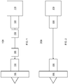
- the system 100 includes an engine 110, which can be coupled to a generator 120.
- a shaft that is coupled to a turbine can cause the rotor of the generator 120 to rotate in the magnetic field of the generator 120 to produce electric power.
- the power from the generator 120 is used to provide power to a motor 130 to drive a fan 140.
- the power from the generator 120 is provided to a power electronics circuit 150 which can convert the AC output of the generator to DC.
- the output of the power electronics circuit 150 can be provided to a power electronics circuit 160 which produces a controlled AC signal to provide to the motor 130.
- FIG. 2 another system 200 is shown.
- the output of the generator 220 is directly coupled to the input of a motor 230 that is used to drive the fan 240.
- the generator 220 outputs an AC signal that is directly proportional to the operation of the engine 210.
- the motor 230 that is used to drive the fan 240 will experience the variation in the operation of the engine 210 which can lead to inefficient operation.
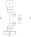
- the engine 310 of FIG. 3 can include several components to convert fuel energy to mechanical energy.
- the engine 310 can be a rotating engine that receives fuel to produce power to rotate a shaft coupled to the generator 320.
- the engine 310 can include a core, a low/high-pressure compressor, and a low/high-pressure turbine (not shown) to convert the fuel energy to rotational energy for the generator 320.
- the first machine 320 is a doubly fed induction generator.
- the rotor of the doubly fed induction generator is controlled by the rotation of the turbine of the engine which causes the rotor to rotate in the magnetic field producing current.
- the doubly fed induction generator can receive an excitation current to rotor windings (not shown) which can modify the electrical power output of the generator.
- the doubly fed induction generator can also receive an excitation current at the stator where the electrical output of the generator is a function of both the magnetic field of the stator and rotor.
- the second machine 330 is a doubly fed induction motor.
- the doubly fed induction motor is configured to receive a first input such as the electrical output from the generator.
- the received input can be a 3-phase AC input and can be provided to the stator to generate a magnetic field in the motor.
- the input is provided to the stator which in turns drives the rotor.
- the doubly fed induction motor can also receive an excitation signal to the rotor to modify the rotational output of the motor. That is, the rotational speed of the shaft of the motor which can be used to drive the fan can be changed and controlled at a desired operational speed using the excitation signal.
- a first power/frequency converter 350 can monitor the output of the generator 320.
- the output of the power/frequency converter 350 can be adjusted to control the output electrical power of the generator 320 as desired. That is, the output of the stator can be modified by the signal from the power/frequency converter 350 provided to the rotor windings to effect the electrical power output the generator 320.
- the converter 350 can detect the AC power and compare it to a threshold level. Based on the comparison the excitation signal can be provided to the rotor of the generator 320 to change the magnetic field which affects the electrical output of the generator 320.
- a second power/frequency converter 360 can monitor an electrical input to the motor 330.
- the converter 360 can compare the input to a threshold level. Based on the comparison the excitation signal can be provided to the rotor of the motor 330 to change the magnetic field which affects the rotational speed of the motor 330.
- a controller 370 can be used to control the operation of the first and second power/frequency converter.
- the power electronics can be sized and reduced.
- the engine 310 can be operated at a reduced optimal speed while providing flexible control an electric motor coupled to a generator.
- the doubly fed induction machines the engine can be operated at a reduced rate or an optimal rate and the fan speed can now be independently controlled.
- the machine 400 includes a stator 410 and a rotor 420 to produce mechanical force when operating as a motor and produce electrical power when operating as a generator.
- the stator 410 is configured to receive excitation signal 430 to energize the stator 410.
- the excitation signal 430 can include an AC or DC signal.
- the rotor 420 can receive an excitation signal 440 to modify the output of the machine 400.
- the electrical output of the machine can be a function of both excitation signals 430, 440.
- the rotational speed of the rotor 440 of the machine 400 can be a function of both excitation signals 430, 440.
- the excitation signals 430, 440 can be provided to windings that are in the rotor 420 or coils in the stator 410.
- the excitation signals 430, 440 can be controlled by system controllers and power/frequency converters such as that shown in FIG. 3 .
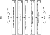
- the method 500 can be implemented in the series hybrid architecture such as that shown in FIG. 3 . It should be understood the method 500 can also be implemented in architectures having a different configuration and is not limited to that shown in FIG. 3 .
- the method 500 begins at block 502 and proceeds to block 504 which provides for generating electrical power at a first machine.
- the electrical power can be generated by a generator such as a doubly fed induction generator.
- the method 500 at block 506 provides for transmitting the electrical power to a second machine to operate the second machine.
- the second machine is a doubly fed induction motor.
- the motor can receive the electrical power at a stator of the motor which causes the rotor to rotate at a speed which can be used to drive equipment such as a fan.
- Block 508 provides for selecting a speed of operation for the second machine.
- the speed can be selected to operate a fan at a desired speed.
- the motor speed is not completely dependent on the electrical power from the generator.
- the method 500 provides for comparing a current speed of operation of the second machine to the selected speed of operation.
- the method 500 includes providing an excitation signal to the second machine based at least in part on the comparison.
- the excitation signal can be an AC excitation signal that is provided to the rotor where the speed of the rotor will be a function of the received AC power from the generator and the received AC excitation signal received at the rotor of the motor.
- the method 500 ends at block 514. It is to be understood that one or more steps can be continuously repeated. In addition, other steps and or a different combination of steps can be used.
- the technical effects and benefits provide an architecture that will use a fraction of the power electronics for minimum weight, volume, and losses while maintaining maximum fan speed control.
- This architecture allows for innovative vehicle architectures and failure mode operation.
- the technical effects and benefits include a reduction in the size of the power electronics. Since the power electronics are now only required to process a fraction of the total power, they can be sized accordingly to reduce its weight, volume, and size.
- the technical effects and benefits allow for the operation of the engine at a reduced speed while maintaining the desired performance at a coupled device such as a motor driving a fan or pump.
Landscapes
- Engineering & Computer Science (AREA)
- Chemical & Material Sciences (AREA)
- Combustion & Propulsion (AREA)
- Transportation (AREA)
- Mechanical Engineering (AREA)
- Power Engineering (AREA)
- Control Of Eletrric Generators (AREA)
Claims (12)
- System, das eine serielle Hybridarchitektur unter Verwendung von zusammengesetzten doppelt gespeisten Induktionsmaschinen beinhaltet, wobei das System Folgendes umfasst:eine Steuerung (370), die dazu konfiguriert ist, den Betrieb des Systems zu steuern;eine Leistungsquelle, die dazu konfiguriert ist, eine erste Energieform in eine zweite Energieform umzuwandeln;eine erste Maschine (320), die dazu konfiguriert ist, Leistung zu erzeugen, wobei die erste Maschine mechanisch an die Leistungsquelle gekoppelt ist;eine zweite Maschine (330), die dazu konfiguriert ist, Ausrüstung zu steuern, wobei die erste Maschine elektrisch an die zweite Maschine gekoppelt ist;eine erste Leistungselektronikschaltung, die dazu konfiguriert ist, elektrische Leistung der ersten Maschine zu modifizieren, dadurch gekennzeichnet, dassdas Modifizieren der elektrischen Leistung der ersten Maschine Folgendes umfasst:Erfassen der elektrischen Leistung an der ersten Leistungselektronikschaltung;Vergleichen der elektrischen Leistung mit einem Wert für einen elektrischen Ausgabepegel;Bereitstellen eines Erregungssignals für die erste Maschine basierend auf dem Vergleich;Modifizieren der elektrischen Leistung basierend auf dem Erregungssignal;Übertragen der modifizierten elektrischen Leistung an eine zweite Maschine, um die zweite Maschine zu betreiben; undeine zweite Leistungselektronikschaltung, die dazu konfiguriert ist, eine Eingabe in die zweite Maschine zu erfassen und ein zweites Signal bereitzustellen, um eine Ausgabe der zweiten Maschine zu steuern, wobei das Bereitstellen des zweiten Signals Folgendes umfasst:Empfangen der modifizierten elektrischen Leistung an der zweiten Leistungselektronikschaltung;Vergleichen der empfangenen modifizierten elektrischen Leistung mit einem Wert für einen Schwellenpegel;Auswählen einer Betriebsgeschwindigkeit für die zweite Maschine durch Steuern des Betriebs der zweiten Maschine;Vergleichen einer aktuellen Betriebsgeschwindigkeit der zweiten Maschine mit der ausgewählten Betriebsgeschwindigkeit; undBereitstellen eines Erregungssignals für die zweite Maschine basierend zumindest teilweise auf dem Vergleich, um die Betriebsgeschwindigkeit der zweiten Maschine zu steuern.
- System nach Anspruch 1, wobei die erste Maschine und die zweite Maschine unabhängig voneinander betrieben werden.
- System nach Anspruch 1, wobei die erste Maschine einen Rotor und einen Stator umfasst und wobei das erste Signal dem Stator der ersten Maschine bereitgestellt wird.
- System nach Anspruch 1, wobei die zweite Maschine einen Rotor und einen Stator umfasst und wobei das zweite Signal dem Rotor der zweiten Maschine bereitgestellt wird.
- System nach einem der vorhergehenden Ansprüche, wobei die Leistungsquelle ein Motor ist.
- Verfahren zum Betreiben einer seriellen Hybridarchitektur unter Verwendung von zusammengesetzten doppelt gespeisten Induktionsmaschinen, wobei das Verfahren Folgendes umfasst:Erzeugen von elektrischer Leistung an einer ersten Maschine (320) ;Modifizieren der elektrischen Ausgabe der ersten Maschine (320), wobei das Modifizieren der elektrischen Leistung der ersten Maschine Folgendes umfasst und durch Folgendes gekennzeichnet ist:Erfassen der elektrischen Leistung an einer ersten Leistungselektronikschaltung;Vergleichen der elektrischen Leistung mit einem Wert für einen elektrischen Ausgabepegel;Bereitstellen eines Erregungssignals für die erste Maschine basierend auf dem Vergleich;Modifizieren der elektrischen Leistung basierend auf dem Erregungssignal;Übertragen der modifizierten elektrischen Leistung an eine zweite Maschine (330), um die zweite Maschine (330) zu betreiben;Empfangen der modifizierten elektrischen Leistung an der zweiten Leistungselektronikschaltung;Vergleichen der empfangenen modifizierten elektrischen Leistung mit einem Wert für einen Schwellenpegel;Auswählen einer Betriebsgeschwindigkeit für die zweite Maschine (330) durch Steuern des Betriebs der zweiten Maschine;Vergleichen einer aktuellen Betriebsgeschwindigkeit der zweiten Maschine (330) mit der ausgewählten Betriebsgeschwindigkeit; undBereitstellen eines Erregungssignals für die zweite Maschine basierend zumindest teilweise auf dem Vergleich, um die Betriebsgeschwindigkeit der zweiten Maschine (330) zu steuern.
- Verfahren nach Anspruch 6, wobei das Bereitstellen des Erregungssignals für die erste Maschine Rotorwicklungen der ersten Maschine bereitgestellt wird.
- Verfahren nach einem der Ansprüche 6 oder 7, wobei das Bereitstellen des Erregungssignals für die zweite Maschine (330) den Rotorwicklungen der zweiten Maschine bereitgestellt wird.
- Verfahren nach einem der Ansprüche 6-8, wobei das Verfahren ferner Empfangen von Leistung an dem Rotor der ersten Maschine (320) umfasst.
- Verfahren nach einem der Ansprüche 6-9, wobei das Verfahren ferner Empfangen der elektrischen Leistung an einem Stator der zweiten Maschine (330) umfasst.
- Verfahren nach einem der Ansprüche 6-10, wobei das Verfahren ferner Empfangen von Energie an der ersten Maschine (320) von einem Motor umfasst.
- Verfahren nach einem der Ansprüche 6-11, wobei das Verfahren ferner unabhängiges Betreiben der ersten Maschine (320) und der zweiten Maschine (330) umfasst.
Applications Claiming Priority (1)
| Application Number | Priority Date | Filing Date | Title |
|---|---|---|---|
| US16/293,822 US11312222B2 (en) | 2019-03-06 | 2019-03-06 | Series hybrid architectures using compounded doubly fed machines |
Publications (2)
| Publication Number | Publication Date |
|---|---|
| EP3706307A1 EP3706307A1 (de) | 2020-09-09 |
| EP3706307B1 true EP3706307B1 (de) | 2022-06-29 |
Family
ID=68732726
Family Applications (1)
| Application Number | Title | Priority Date | Filing Date |
|---|---|---|---|
| EP19212246.3A Revoked EP3706307B1 (de) | 2019-03-06 | 2019-11-28 | Serielle hybridarchitekturen unter verwendung von gekoppelten doppelt gespeisten maschinen |
Country Status (2)
| Country | Link |
|---|---|
| US (1) | US11312222B2 (de) |
| EP (1) | EP3706307B1 (de) |
Families Citing this family (1)
| Publication number | Priority date | Publication date | Assignee | Title |
|---|---|---|---|---|
| EP3920406A1 (de) * | 2020-06-04 | 2021-12-08 | Siemens Gamesa Renewable Energy Innovation & Technology S.L. | System und verfahren zur erzeugung elektrischer energie durch eine windturbine |
Family Cites Families (7)
| Publication number | Priority date | Publication date | Assignee | Title |
|---|---|---|---|---|
| US4982147A (en) | 1989-01-30 | 1991-01-01 | State Of Oregon Acting By And Through The State Board Of Higher Education On Behalf Of Oregon State University | Power factor motor control system |
| US8093739B2 (en) * | 2009-01-09 | 2012-01-10 | General Electric Company | System and method for fixed frequency power generation |
| CN102458900A (zh) * | 2009-06-25 | 2012-05-16 | 菲斯科汽车公司 | 用于多发动机混合动力驱动系统的直接电连接 |
| GB201308292D0 (en) | 2013-05-09 | 2013-06-12 | Rolls Royce Plc | Aircraft electrical system |
| CA2932101C (en) * | 2015-06-10 | 2023-10-03 | Rolls-Royce Corporation | Synchronizing motors for an electric propulsion system |
| US10718598B2 (en) * | 2017-06-23 | 2020-07-21 | Hamilton Sundstrand Corporation | Series hybrid architecture for an unmanned underwater vehicle propulsion system |
| ES2899867T3 (es) | 2017-08-18 | 2022-03-15 | Ge Energy Power Conversion Technology Ltd | Sistema y procedimiento para operar una central hidroeléctrica de acumulación por bombeo con una máquina asíncrona de doble alimentación |
-
2019
- 2019-03-06 US US16/293,822 patent/US11312222B2/en active Active
- 2019-11-28 EP EP19212246.3A patent/EP3706307B1/de not_active Revoked
Non-Patent Citations (5)
| Title |
|---|
| ANONYMOUS: "Setpoint (control system)", WIKIPEDIA, 4 January 2019 (2019-01-04), pages 1 - 2, XP093148536, Retrieved from the Internet <URL:https://en.wikipedia.org/w/index.php?title=Setpoint_(control_system)&oldid=876838730> [retrieved on 20240405] |
| DAVID J. SADEY, LINDA TAYLOR, RAYMOND BEACH: "Proposal and Development of a High Voltage Variable Frequency Alternating Current Power System for Hybrid Electric Aircraft", 14TH INTERNATIONAL ENERGY CONVERSION ENGINEERING CONFERENCE, 25 July 2016 (2016-07-25), Reston, Virginia , pages 1 - 10, XP055750143, ISBN: 978-1-62410-407-7, DOI: 10.2514/6.2016-4928 |
| FREDERIC POITIERS: "Etude et commande generatrices asynchrones pour l'utilisation de l'energie eolienne", THÈSE DE DOCTORAT, 1 January 2003 (2003-01-01), pages 1 - 156, XP093086358 |
| SADEY DAVID J., BODSON MARC, CSANK JEFFREY, HUNKER KEITH, THEMAN CASEY, TAYLOR LINDA: "Control Demonstration of Multiple Doubly-Fed Induction Motors for Hybrid Electric Propulsion", 53RD AIAA/SAE/ASEE JOINT PROPULSION CONFERENCE, AMERICAN INSTITUTE OF AERONAUTICS AND ASTRONAUTICS, RESTON, VIRGINIA, 10 July 2017 (2017-07-10) - 12 July 2017 (2017-07-12), Reston, Virginia , pages 1 - 13, XP093148546, ISBN: 978-1-62410-511-1, DOI: 10.2514/6.2017-4954 |
| W. BEITZ UND K.-H. KÜTTNER: "Dubbel Taschenbuch der Maschinenbau", 1 January 1990, SPRINGER, DE, ISBN: 3-540-52381-2, article W. BEITZ, K.-H. KÜTTNER: "Section X Regelungstechnik", pages: X1 - X18, XP009553260 |
Also Published As
| Publication number | Publication date |
|---|---|
| US11312222B2 (en) | 2022-04-26 |
| US20200282819A1 (en) | 2020-09-10 |
| EP3706307A1 (de) | 2020-09-09 |
Similar Documents
| Publication | Publication Date | Title |
|---|---|---|
| US9209741B2 (en) | Method and system for controlling synchronous machine as generator/starter | |
| US7514806B2 (en) | Engine start system with quadrature AC excitation | |
| US7915869B2 (en) | Single stage starter/generator with rotor quadrature AC excitation | |
| US9573539B2 (en) | Electric system architecture for more-electric engine accessories | |
| Bu et al. | Induction-machine-based starter/generator systems: Techniques, developments, and advances | |
| US8097968B2 (en) | Position-controlled start from the AC line using a synchronous machine | |
| CN110015433B (zh) | 交流配电系统和交流配电方法 | |
| EP3706307B1 (de) | Serielle hybridarchitekturen unter verwendung von gekoppelten doppelt gespeisten maschinen | |
| CN108847796B (zh) | 三级式无刷同步电机磁阻式起动控制方法及系统 | |
| US12199539B2 (en) | Motor control device, electric vehicle, and motor control method | |
| EP4510431A1 (de) | Elektrische asynchronmaschine mit transversalem fluss | |
| EP3376663A1 (de) | Generatoranordnungen und verfahren zur steuerung von generatoranordnungen | |
| EP4401302A1 (de) | Starter/generator-anordnungen für gasturbinenmotoren | |
| EP4401301A1 (de) | Starter/generator-anordnungen für gasturbinenmotoren | |
| CN106059446A (zh) | 六相永磁同步直线电机单相开路故障的容错控制方法 | |
| US12512743B2 (en) | Motor-alternator-motor (MAM) systems and methods for using same | |
| Song et al. | A new topology and control scheme for 4WD HEV using a DFIM with a reduced size converter-inverter | |
| Mecke | Permanent magnet synchronous motor for passenger ship propulsion | |
| EP2928069A2 (de) | Systeme mit steuerbarem Spannungs-Wechselstromgeneratorsystem | |
| Reshetnikov et al. | Modeling of integrated starter-generator in generator mode | |
| US12428998B2 (en) | Aircraft engine start using multiple common motor controllers | |
| Koczara et al. | Variable speed integrated generating set an emerging technology for distributed power generation | |
| CN115443606B (zh) | 带有谐波馈电的驱动系统 | |
| Andrade et al. | Voltage and current control of self-excited Switched Reluctance Generator for variable speed drive | |
| RU2278463C1 (ru) | Система электродвижения |
Legal Events
| Date | Code | Title | Description |
|---|---|---|---|
| PUAI | Public reference made under article 153(3) epc to a published international application that has entered the european phase |
Free format text: ORIGINAL CODE: 0009012 |
|
| STAA | Information on the status of an ep patent application or granted ep patent |
Free format text: STATUS: THE APPLICATION HAS BEEN PUBLISHED |
|
| AK | Designated contracting states |
Kind code of ref document: A1 Designated state(s): AL AT BE BG CH CY CZ DE DK EE ES FI FR GB GR HR HU IE IS IT LI LT LU LV MC MK MT NL NO PL PT RO RS SE SI SK SM TR |
|
| AX | Request for extension of the european patent |
Extension state: BA ME |
|
| STAA | Information on the status of an ep patent application or granted ep patent |
Free format text: STATUS: REQUEST FOR EXAMINATION WAS MADE |
|
| 17P | Request for examination filed |
Effective date: 20210308 |
|
| RBV | Designated contracting states (corrected) |
Designated state(s): AL AT BE BG CH CY CZ DE DK EE ES FI FR GB GR HR HU IE IS IT LI LT LU LV MC MK MT NL NO PL PT RO RS SE SI SK SM TR |
|
| RIN1 | Information on inventor provided before grant (corrected) |
Inventor name: SPIERLING, TODD A. |
|
| STAA | Information on the status of an ep patent application or granted ep patent |
Free format text: STATUS: EXAMINATION IS IN PROGRESS |
|
| 17Q | First examination report despatched |
Effective date: 20210510 |
|
| GRAP | Despatch of communication of intention to grant a patent |
Free format text: ORIGINAL CODE: EPIDOSNIGR1 |
|
| STAA | Information on the status of an ep patent application or granted ep patent |
Free format text: STATUS: GRANT OF PATENT IS INTENDED |
|
| INTG | Intention to grant announced |
Effective date: 20220203 |
|
| GRAS | Grant fee paid |
Free format text: ORIGINAL CODE: EPIDOSNIGR3 |
|
| GRAA | (expected) grant |
Free format text: ORIGINAL CODE: 0009210 |
|
| STAA | Information on the status of an ep patent application or granted ep patent |
Free format text: STATUS: THE PATENT HAS BEEN GRANTED |
|
| AK | Designated contracting states |
Kind code of ref document: B1 Designated state(s): AL AT BE BG CH CY CZ DE DK EE ES FI FR GB GR HR HU IE IS IT LI LT LU LV MC MK MT NL NO PL PT RO RS SE SI SK SM TR |
|
| REG | Reference to a national code |
Ref country code: CH Ref legal event code: EP |
|
| REG | Reference to a national code |
Ref country code: DE Ref legal event code: R096 Ref document number: 602019016396 Country of ref document: DE |
|
| REG | Reference to a national code |
Ref country code: AT Ref legal event code: REF Ref document number: 1501995 Country of ref document: AT Kind code of ref document: T Effective date: 20220715 |
|
| REG | Reference to a national code |
Ref country code: IE Ref legal event code: FG4D |
|
| REG | Reference to a national code |
Ref country code: LT Ref legal event code: MG9D |
|
| PG25 | Lapsed in a contracting state [announced via postgrant information from national office to epo] |
Ref country code: SE Free format text: LAPSE BECAUSE OF FAILURE TO SUBMIT A TRANSLATION OF THE DESCRIPTION OR TO PAY THE FEE WITHIN THE PRESCRIBED TIME-LIMIT Effective date: 20220629 Ref country code: NO Free format text: LAPSE BECAUSE OF FAILURE TO SUBMIT A TRANSLATION OF THE DESCRIPTION OR TO PAY THE FEE WITHIN THE PRESCRIBED TIME-LIMIT Effective date: 20220929 Ref country code: LT Free format text: LAPSE BECAUSE OF FAILURE TO SUBMIT A TRANSLATION OF THE DESCRIPTION OR TO PAY THE FEE WITHIN THE PRESCRIBED TIME-LIMIT Effective date: 20220629 Ref country code: HR Free format text: LAPSE BECAUSE OF FAILURE TO SUBMIT A TRANSLATION OF THE DESCRIPTION OR TO PAY THE FEE WITHIN THE PRESCRIBED TIME-LIMIT Effective date: 20220629 Ref country code: GR Free format text: LAPSE BECAUSE OF FAILURE TO SUBMIT A TRANSLATION OF THE DESCRIPTION OR TO PAY THE FEE WITHIN THE PRESCRIBED TIME-LIMIT Effective date: 20220930 Ref country code: FI Free format text: LAPSE BECAUSE OF FAILURE TO SUBMIT A TRANSLATION OF THE DESCRIPTION OR TO PAY THE FEE WITHIN THE PRESCRIBED TIME-LIMIT Effective date: 20220629 Ref country code: BG Free format text: LAPSE BECAUSE OF FAILURE TO SUBMIT A TRANSLATION OF THE DESCRIPTION OR TO PAY THE FEE WITHIN THE PRESCRIBED TIME-LIMIT Effective date: 20220929 |
|
| REG | Reference to a national code |
Ref country code: NL Ref legal event code: MP Effective date: 20220629 |
|
| REG | Reference to a national code |
Ref country code: AT Ref legal event code: MK05 Ref document number: 1501995 Country of ref document: AT Kind code of ref document: T Effective date: 20220629 |
|
| PG25 | Lapsed in a contracting state [announced via postgrant information from national office to epo] |
Ref country code: RS Free format text: LAPSE BECAUSE OF FAILURE TO SUBMIT A TRANSLATION OF THE DESCRIPTION OR TO PAY THE FEE WITHIN THE PRESCRIBED TIME-LIMIT Effective date: 20220629 Ref country code: LV Free format text: LAPSE BECAUSE OF FAILURE TO SUBMIT A TRANSLATION OF THE DESCRIPTION OR TO PAY THE FEE WITHIN THE PRESCRIBED TIME-LIMIT Effective date: 20220629 |
|
| PG25 | Lapsed in a contracting state [announced via postgrant information from national office to epo] |
Ref country code: NL Free format text: LAPSE BECAUSE OF FAILURE TO SUBMIT A TRANSLATION OF THE DESCRIPTION OR TO PAY THE FEE WITHIN THE PRESCRIBED TIME-LIMIT Effective date: 20220629 |
|
| PG25 | Lapsed in a contracting state [announced via postgrant information from national office to epo] |
Ref country code: SM Free format text: LAPSE BECAUSE OF FAILURE TO SUBMIT A TRANSLATION OF THE DESCRIPTION OR TO PAY THE FEE WITHIN THE PRESCRIBED TIME-LIMIT Effective date: 20220629 Ref country code: SK Free format text: LAPSE BECAUSE OF FAILURE TO SUBMIT A TRANSLATION OF THE DESCRIPTION OR TO PAY THE FEE WITHIN THE PRESCRIBED TIME-LIMIT Effective date: 20220629 Ref country code: RO Free format text: LAPSE BECAUSE OF FAILURE TO SUBMIT A TRANSLATION OF THE DESCRIPTION OR TO PAY THE FEE WITHIN THE PRESCRIBED TIME-LIMIT Effective date: 20220629 Ref country code: PT Free format text: LAPSE BECAUSE OF FAILURE TO SUBMIT A TRANSLATION OF THE DESCRIPTION OR TO PAY THE FEE WITHIN THE PRESCRIBED TIME-LIMIT Effective date: 20221031 Ref country code: ES Free format text: LAPSE BECAUSE OF FAILURE TO SUBMIT A TRANSLATION OF THE DESCRIPTION OR TO PAY THE FEE WITHIN THE PRESCRIBED TIME-LIMIT Effective date: 20220629 Ref country code: EE Free format text: LAPSE BECAUSE OF FAILURE TO SUBMIT A TRANSLATION OF THE DESCRIPTION OR TO PAY THE FEE WITHIN THE PRESCRIBED TIME-LIMIT Effective date: 20220629 Ref country code: AT Free format text: LAPSE BECAUSE OF FAILURE TO SUBMIT A TRANSLATION OF THE DESCRIPTION OR TO PAY THE FEE WITHIN THE PRESCRIBED TIME-LIMIT Effective date: 20220629 |
|
| PG25 | Lapsed in a contracting state [announced via postgrant information from national office to epo] |
Ref country code: PL Free format text: LAPSE BECAUSE OF FAILURE TO SUBMIT A TRANSLATION OF THE DESCRIPTION OR TO PAY THE FEE WITHIN THE PRESCRIBED TIME-LIMIT Effective date: 20220629 Ref country code: IS Free format text: LAPSE BECAUSE OF FAILURE TO SUBMIT A TRANSLATION OF THE DESCRIPTION OR TO PAY THE FEE WITHIN THE PRESCRIBED TIME-LIMIT Effective date: 20221029 |
|
| REG | Reference to a national code |
Ref country code: DE Ref legal event code: R026 Ref document number: 602019016396 Country of ref document: DE |
|
| PG25 | Lapsed in a contracting state [announced via postgrant information from national office to epo] |
Ref country code: AL Free format text: LAPSE BECAUSE OF FAILURE TO SUBMIT A TRANSLATION OF THE DESCRIPTION OR TO PAY THE FEE WITHIN THE PRESCRIBED TIME-LIMIT Effective date: 20220629 |
|
| PLBI | Opposition filed |
Free format text: ORIGINAL CODE: 0009260 |
|
| PLAX | Notice of opposition and request to file observation + time limit sent |
Free format text: ORIGINAL CODE: EPIDOSNOBS2 |
|
| PG25 | Lapsed in a contracting state [announced via postgrant information from national office to epo] |
Ref country code: DK Free format text: LAPSE BECAUSE OF FAILURE TO SUBMIT A TRANSLATION OF THE DESCRIPTION OR TO PAY THE FEE WITHIN THE PRESCRIBED TIME-LIMIT Effective date: 20220629 Ref country code: CZ Free format text: LAPSE BECAUSE OF FAILURE TO SUBMIT A TRANSLATION OF THE DESCRIPTION OR TO PAY THE FEE WITHIN THE PRESCRIBED TIME-LIMIT Effective date: 20220629 |
|
| 26 | Opposition filed |
Opponent name: SAFRAN AIRCRAFT ENGINES Effective date: 20230327 |
|
| PG25 | Lapsed in a contracting state [announced via postgrant information from national office to epo] |
Ref country code: MC Free format text: LAPSE BECAUSE OF FAILURE TO SUBMIT A TRANSLATION OF THE DESCRIPTION OR TO PAY THE FEE WITHIN THE PRESCRIBED TIME-LIMIT Effective date: 20220629 |
|
| REG | Reference to a national code |
Ref country code: CH Ref legal event code: PL |
|
| P01 | Opt-out of the competence of the unified patent court (upc) registered |
Effective date: 20230603 |
|
| REG | Reference to a national code |
Ref country code: BE Ref legal event code: MM Effective date: 20221130 |
|
| PG25 | Lapsed in a contracting state [announced via postgrant information from national office to epo] |
Ref country code: LI Free format text: LAPSE BECAUSE OF NON-PAYMENT OF DUE FEES Effective date: 20221130 Ref country code: CH Free format text: LAPSE BECAUSE OF NON-PAYMENT OF DUE FEES Effective date: 20221130 |
|
| PLBB | Reply of patent proprietor to notice(s) of opposition received |
Free format text: ORIGINAL CODE: EPIDOSNOBS3 |
|
| PG25 | Lapsed in a contracting state [announced via postgrant information from national office to epo] |
Ref country code: SI Free format text: LAPSE BECAUSE OF FAILURE TO SUBMIT A TRANSLATION OF THE DESCRIPTION OR TO PAY THE FEE WITHIN THE PRESCRIBED TIME-LIMIT Effective date: 20220629 Ref country code: LU Free format text: LAPSE BECAUSE OF NON-PAYMENT OF DUE FEES Effective date: 20221128 |
|
| PG25 | Lapsed in a contracting state [announced via postgrant information from national office to epo] |
Ref country code: IE Free format text: LAPSE BECAUSE OF NON-PAYMENT OF DUE FEES Effective date: 20221128 |
|
| PG25 | Lapsed in a contracting state [announced via postgrant information from national office to epo] |
Ref country code: BE Free format text: LAPSE BECAUSE OF NON-PAYMENT OF DUE FEES Effective date: 20221130 |
|
| PG25 | Lapsed in a contracting state [announced via postgrant information from national office to epo] |
Ref country code: IT Free format text: LAPSE BECAUSE OF FAILURE TO SUBMIT A TRANSLATION OF THE DESCRIPTION OR TO PAY THE FEE WITHIN THE PRESCRIBED TIME-LIMIT Effective date: 20220629 |
|
| PG25 | Lapsed in a contracting state [announced via postgrant information from national office to epo] |
Ref country code: CY Free format text: LAPSE BECAUSE OF FAILURE TO SUBMIT A TRANSLATION OF THE DESCRIPTION OR TO PAY THE FEE WITHIN THE PRESCRIBED TIME-LIMIT Effective date: 20220629 |
|
| PG25 | Lapsed in a contracting state [announced via postgrant information from national office to epo] |
Ref country code: MK Free format text: LAPSE BECAUSE OF FAILURE TO SUBMIT A TRANSLATION OF THE DESCRIPTION OR TO PAY THE FEE WITHIN THE PRESCRIBED TIME-LIMIT Effective date: 20220629 Ref country code: HU Free format text: LAPSE BECAUSE OF FAILURE TO SUBMIT A TRANSLATION OF THE DESCRIPTION OR TO PAY THE FEE WITHIN THE PRESCRIBED TIME-LIMIT; INVALID AB INITIO Effective date: 20191128 |
|
| PG25 | Lapsed in a contracting state [announced via postgrant information from national office to epo] |
Ref country code: MT Free format text: LAPSE BECAUSE OF FAILURE TO SUBMIT A TRANSLATION OF THE DESCRIPTION OR TO PAY THE FEE WITHIN THE PRESCRIBED TIME-LIMIT Effective date: 20220629 |
|
| PG25 | Lapsed in a contracting state [announced via postgrant information from national office to epo] |
Ref country code: BG Free format text: LAPSE BECAUSE OF FAILURE TO SUBMIT A TRANSLATION OF THE DESCRIPTION OR TO PAY THE FEE WITHIN THE PRESCRIBED TIME-LIMIT Effective date: 20220629 |
|
| PG25 | Lapsed in a contracting state [announced via postgrant information from national office to epo] |
Ref country code: BG Free format text: LAPSE BECAUSE OF FAILURE TO SUBMIT A TRANSLATION OF THE DESCRIPTION OR TO PAY THE FEE WITHIN THE PRESCRIBED TIME-LIMIT Effective date: 20220629 |
|
| PGFP | Annual fee paid to national office [announced via postgrant information from national office to epo] |
Ref country code: DE Payment date: 20241022 Year of fee payment: 6 |
|
| PGFP | Annual fee paid to national office [announced via postgrant information from national office to epo] |
Ref country code: GB Payment date: 20241023 Year of fee payment: 6 |
|
| PGFP | Annual fee paid to national office [announced via postgrant information from national office to epo] |
Ref country code: FR Payment date: 20241022 Year of fee payment: 6 |
|
| RDAF | Communication despatched that patent is revoked |
Free format text: ORIGINAL CODE: EPIDOSNREV1 |
|
| REG | Reference to a national code |
Ref country code: DE Ref legal event code: R064 Ref document number: 602019016396 Country of ref document: DE Ref country code: DE Ref legal event code: R103 Ref document number: 602019016396 Country of ref document: DE |
|
| RDAG | Patent revoked |
Free format text: ORIGINAL CODE: 0009271 |
|
| STAA | Information on the status of an ep patent application or granted ep patent |
Free format text: STATUS: PATENT REVOKED |
|
| REG | Reference to a national code |
Ref country code: CH Ref legal event code: PL |
|
| 27W | Patent revoked |
Effective date: 20250411 |
|
| GBPR | Gb: patent revoked under art. 102 of the ep convention designating the uk as contracting state |
Effective date: 20250411 |
|
| PG25 | Lapsed in a contracting state [announced via postgrant information from national office to epo] |
Ref country code: TR Free format text: LAPSE BECAUSE OF FAILURE TO SUBMIT A TRANSLATION OF THE DESCRIPTION OR TO PAY THE FEE WITHIN THE PRESCRIBED TIME-LIMIT Effective date: 20220629 |