EP3706305A1 - Domestic appliance and method for operating such a domestic appliance - Google Patents
Domestic appliance and method for operating such a domestic appliance Download PDFInfo
- Publication number
- EP3706305A1 EP3706305A1 EP19161314.0A EP19161314A EP3706305A1 EP 3706305 A1 EP3706305 A1 EP 3706305A1 EP 19161314 A EP19161314 A EP 19161314A EP 3706305 A1 EP3706305 A1 EP 3706305A1
- Authority
- EP
- European Patent Office
- Prior art keywords
- functional unit
- switching
- current
- drive device
- household appliance
- Prior art date
- Legal status (The legal status is an assumption and is not a legal conclusion. Google has not performed a legal analysis and makes no representation as to the accuracy of the status listed.)
- Pending
Links
Images


Classifications
-
- H—ELECTRICITY
- H02—GENERATION; CONVERSION OR DISTRIBUTION OF ELECTRIC POWER
- H02P—CONTROL OR REGULATION OF ELECTRIC MOTORS, ELECTRIC GENERATORS OR DYNAMO-ELECTRIC CONVERTERS; CONTROLLING TRANSFORMERS, REACTORS OR CHOKE COILS
- H02P1/00—Arrangements for starting electric motors or dynamo-electric converters
- H02P1/16—Arrangements for starting electric motors or dynamo-electric converters for starting dynamo-electric motors or dynamo-electric converters
- H02P1/163—Arrangements for starting electric motors or dynamo-electric converters for starting dynamo-electric motors or dynamo-electric converters for starting an individual reluctance motor
-
- A—HUMAN NECESSITIES
- A47—FURNITURE; DOMESTIC ARTICLES OR APPLIANCES; COFFEE MILLS; SPICE MILLS; SUCTION CLEANERS IN GENERAL
- A47J—KITCHEN EQUIPMENT; COFFEE MILLS; SPICE MILLS; APPARATUS FOR MAKING BEVERAGES
- A47J43/00—Implements for preparing or holding food, not provided for in other groups of this subclass
- A47J43/04—Machines for domestic use not covered elsewhere, e.g. for grinding, mixing, stirring, kneading, emulsifying, whipping or beating foodstuffs, e.g. power-driven
- A47J43/07—Parts or details, e.g. mixing tools, whipping tools
- A47J43/075—Safety devices
- A47J43/0761—Safety devices for machines with tools driven from the lower side
-
- H—ELECTRICITY
- H02—GENERATION; CONVERSION OR DISTRIBUTION OF ELECTRIC POWER
- H02H—EMERGENCY PROTECTIVE CIRCUIT ARRANGEMENTS
- H02H9/00—Emergency protective circuit arrangements for limiting excess current or voltage without disconnection
- H02H9/02—Emergency protective circuit arrangements for limiting excess current or voltage without disconnection responsive to excess current
-
- A—HUMAN NECESSITIES
- A47—FURNITURE; DOMESTIC ARTICLES OR APPLIANCES; COFFEE MILLS; SPICE MILLS; SUCTION CLEANERS IN GENERAL
- A47J—KITCHEN EQUIPMENT; COFFEE MILLS; SPICE MILLS; APPARATUS FOR MAKING BEVERAGES
- A47J27/00—Cooking-vessels
- A47J27/004—Cooking-vessels with integral electrical heating means
-
- A—HUMAN NECESSITIES
- A47—FURNITURE; DOMESTIC ARTICLES OR APPLIANCES; COFFEE MILLS; SPICE MILLS; SUCTION CLEANERS IN GENERAL
- A47J—KITCHEN EQUIPMENT; COFFEE MILLS; SPICE MILLS; APPARATUS FOR MAKING BEVERAGES
- A47J43/00—Implements for preparing or holding food, not provided for in other groups of this subclass
- A47J43/04—Machines for domestic use not covered elsewhere, e.g. for grinding, mixing, stirring, kneading, emulsifying, whipping or beating foodstuffs, e.g. power-driven
- A47J43/046—Machines for domestic use not covered elsewhere, e.g. for grinding, mixing, stirring, kneading, emulsifying, whipping or beating foodstuffs, e.g. power-driven with tools driven from the bottom side
-
- A—HUMAN NECESSITIES
- A47—FURNITURE; DOMESTIC ARTICLES OR APPLIANCES; COFFEE MILLS; SPICE MILLS; SUCTION CLEANERS IN GENERAL
- A47J—KITCHEN EQUIPMENT; COFFEE MILLS; SPICE MILLS; APPARATUS FOR MAKING BEVERAGES
- A47J43/00—Implements for preparing or holding food, not provided for in other groups of this subclass
- A47J43/04—Machines for domestic use not covered elsewhere, e.g. for grinding, mixing, stirring, kneading, emulsifying, whipping or beating foodstuffs, e.g. power-driven
- A47J43/07—Parts or details, e.g. mixing tools, whipping tools
- A47J43/0716—Parts or details, e.g. mixing tools, whipping tools for machines with tools driven from the lower side
- A47J43/0722—Mixing, whipping or cutting tools
-
- H—ELECTRICITY
- H02—GENERATION; CONVERSION OR DISTRIBUTION OF ELECTRIC POWER
- H02H—EMERGENCY PROTECTIVE CIRCUIT ARRANGEMENTS
- H02H9/00—Emergency protective circuit arrangements for limiting excess current or voltage without disconnection
- H02H9/001—Emergency protective circuit arrangements for limiting excess current or voltage without disconnection limiting speed of change of electric quantities, e.g. soft switching on or off
- H02H9/002—Emergency protective circuit arrangements for limiting excess current or voltage without disconnection limiting speed of change of electric quantities, e.g. soft switching on or off limiting inrush current on switching on of inductive loads subjected to remanence, e.g. transformers
-
- H—ELECTRICITY
- H02—GENERATION; CONVERSION OR DISTRIBUTION OF ELECTRIC POWER
- H02J—CIRCUIT ARRANGEMENTS OR SYSTEMS FOR SUPPLYING OR DISTRIBUTING ELECTRIC POWER; SYSTEMS FOR STORING ELECTRIC ENERGY
- H02J7/00—Circuit arrangements for charging or depolarising batteries or for supplying loads from batteries
- H02J7/34—Parallel operation in networks using both storage and other dc sources, e.g. providing buffering
- H02J7/345—Parallel operation in networks using both storage and other dc sources, e.g. providing buffering using capacitors as storage or buffering devices
-
- H—ELECTRICITY
- H02—GENERATION; CONVERSION OR DISTRIBUTION OF ELECTRIC POWER
- H02P—CONTROL OR REGULATION OF ELECTRIC MOTORS, ELECTRIC GENERATORS OR DYNAMO-ELECTRIC CONVERTERS; CONTROLLING TRANSFORMERS, REACTORS OR CHOKE COILS
- H02P29/00—Arrangements for regulating or controlling electric motors, appropriate for both AC and DC motors
-
- H—ELECTRICITY
- H05—ELECTRIC TECHNIQUES NOT OTHERWISE PROVIDED FOR
- H05B—ELECTRIC HEATING; ELECTRIC LIGHT SOURCES NOT OTHERWISE PROVIDED FOR; CIRCUIT ARRANGEMENTS FOR ELECTRIC LIGHT SOURCES, IN GENERAL
- H05B3/00—Ohmic-resistance heating
- H05B3/0014—Devices wherein the heating current flows through particular resistances
-
- A—HUMAN NECESSITIES
- A47—FURNITURE; DOMESTIC ARTICLES OR APPLIANCES; COFFEE MILLS; SPICE MILLS; SUCTION CLEANERS IN GENERAL
- A47J—KITCHEN EQUIPMENT; COFFEE MILLS; SPICE MILLS; APPARATUS FOR MAKING BEVERAGES
- A47J43/00—Implements for preparing or holding food, not provided for in other groups of this subclass
- A47J43/04—Machines for domestic use not covered elsewhere, e.g. for grinding, mixing, stirring, kneading, emulsifying, whipping or beating foodstuffs, e.g. power-driven
- A47J43/07—Parts or details, e.g. mixing tools, whipping tools
- A47J43/0716—Parts or details, e.g. mixing tools, whipping tools for machines with tools driven from the lower side
Definitions
- the invention relates to a household appliance according to the preamble of the independent device claim and a method for operating a household appliance.
- the household appliance has a movable first functional unit for providing a first device function for a user, an electrical second Functional unit for providing a second device function for the user, and a drive device for driving the first functional unit.
- the drive device also has an electric motor, a connection for supplying energy to the electric motor and an upstream connection, the upstream connection being connected between the connection and the electric motor.
- the upstream circuit has a current limiting element for limiting a current (when the drive device is switched on or started up; this means: during the period of time).
- the current limiting element is formed by the second functional unit.
- the series connection can in particular also be referred to as a series connection unit.
- Limiting the current can in particular mean limiting a current peak, an inrush current and / or a starting current.
- a current parameter can preferably be reduced in particular to a harmless value.
- the current limiting element can be connected to the electric motor in such a way that the current limiting element forms a starting resistor for the electric motor.
- the current limiting element is connected in series to the electric motor and / or to the connection.
- the upstream circuit can preferably be designed to temporarily limit the current, e.g. B. by the current limiting element can be activated and / or deactivated.
- an electrical connection for connection to a power grid and / or to an energy store, such as. B. a battery can be understood.
- the connection can also be permanently connected to the power grid and / or the energy store while the household appliance is in operation.
- the first and / or the second device function can be understood to mean, in particular, a main use of the household device.
- the first function provides a first benefit (for example stirring and / or chopping) for the user by the household appliance
- the second device function provides a second benefit (e.g. heating and / or cooking).
- the first and second device functions can be device functions that are independent of one another.
- the entire second functional unit can form the current limiting element or part of the second functional unit can form the current limiting element.
- the current limiting element is formed by the second functional unit
- an additional benefit of the second functional unit can be generated in that it serves on the one hand to provide the second device function and on the other hand as a current limiting element. It can be provided that the second functional unit only temporarily forms the current limiting element and is electrically disconnected from the upstream circuit when limiting the current, e.g. B. after switching on, is no longer necessary.
- an additional series resistor in particular in the form of an additional component, can be omitted, so that related costs and installation space can be saved.
- the household appliance is also made robust, because by saving an additional resistance component, another weak point is eliminated, the z. B. in the event of vibrations (e.g. breakage of the ceramic from the resistor) could be damaged.
- the second functional unit can preferably also have a measuring sensor for measuring a current parameter.
- the measuring sensor can be connected to the current limiting element in such a way that the measuring sensor can measure the current of the upstream circuit at the current limiting element and / or a current flow during operation of the second functional unit.
- a maximum capacity of a capacity of the drive device can be determined, and thus in particular their functionality and / or state of charge are checked.
- a sensor which is already present on the second functional unit can thus be used.
- further monitoring functions of the second functional unit can also be transferable to the current limiting element and / or the drive device or can be used twice.
- the current parameter can in particular include an electrical voltage and / or a current intensity.
- the time of switching from a protective switching state I (when switching on or starting up) to an operating switching state II (normal operation of the first functional unit after switching on or starting up) can also be determined.
- the drive device comprises a capacitance that can be charged via the connection, the current limiting element being designed to limit the current when the capacitance is charged, in particular the capacitance being an intermediate circuit capacitor.
- the current limiting element can be designed as a precharge resistor.
- the Capacitance furthermore have a film capacitor and / or electrolytic capacitor. If the capacitance is at least one intermediate circuit capacitor, the drive device can furthermore have a rectifier via which the electric motor can be energized and / or controlled.
- the capacitance can represent an electrical component which has a high charging current at least temporarily.
- a capacitance in the form of an intermediate circuit capacitor can behave like a short circuit when it is completely discharged.
- the first movable functional unit is a safety-relevant functional unit, however, it may be desirable to completely discharge the chargeable capacity when the engine is stopped.
- the motor does not trigger due to a malfunction and thus the safety-relevant function is carried out if a user does not expect this.
- This can be the case, for example, with a kitchen appliance which has an agitator and / or a mixer and whose electric motor requires a chargeable capacity.
- the robustness of the device can be further increased by designing the capacitor as a film capacitor and / or electrolytic capacitor. Such capacitors are such. B. temperature resistant over a wide temperature range and have a high reliability.
- the second functional unit comprises an electrical resistance heater, the current-limiting element being formed by at least one area of a resistance element for heating the resistance heater.
- the resistance element can, for. B. comprise a wire and / or a conductor track, and heat up when energized.
- the resistance element can be at least partially incorporated into the upstream circuit by this z. B. is or can be interconnected with the upstream connection.
- the electrical resistance heating can, for. B. serve in a kitchen appliance for heating food or perform a different temperature function in the household appliance.
- the heating of the resistance heater by the resistance element can represent the second device function.
- the resistance element can form the current limiting element in some areas or completely.
- the electrical resistance heating can thus the prerequisites exist to integrate the second functional unit, in particular without significant structural changes to the second functional unit, as a current limiting element in the upstream circuit.
- the electrical resistance heater is a robust element which can be used as a current limiting element in a cost-effective and simple manner.
- the upstream connection can preferably comprise a switching unit, through which the upstream connection at least between a protective switching state I, in which a current can be limited by the current limiting element (when switching on or starting), and an (chronologically following) operating switching state II, in which the Current limiting element is deactivated (in normal operation), is switchable.
- a protective switching state I in which a current can be limited by the current limiting element (when switching on or starting)
- an (chronologically following) operating switching state II in which the Current limiting element is deactivated (in normal operation)
- the fact that the current limiting element is deactivated in the operating switching state can in particular be understood to mean that the current limiting element is bridged and / or is electrically separated from the connection and / or from the electric motor.
- the current-limiting element can thus be deactivated when a current peak has subsided or the risk of a current peak or a high current no longer occurring.
- the switching unit for switching between the protective switching state and the operating switching state comprises at least one first switching element, which is connected in parallel to the current limiting element, and a second switching element, which is connected in series with the current limiting element.
- the first switching element which is connected in parallel with the current limiting element, can form a current path through which the current limiting element can be bridged.
- the second switching element which is connected in series with the current limiting element, the current limiting element can be electrically isolated from the connection and / or from the electric motor. As a result, no current flows through when the second switching element is opened the current limiting element and an electrical decoupling of the first and second functional unit can be realized.
- the first and / or second switching element can be switchable with software and / or hardware support.
- the switchover unit can thus create a robust possibility of switching between the protective switching state and the operating switching state and of electrically isolating the current-limiting element in a reliable manner.
- the motor and / or capacitor can be completely electrically isolated from an energy source.
- the switchover unit can preferably have a third switching element, by means of which the safety state can be achieved when the first, second and third switching elements are open. As a result, a complete separation of the electric motor and / or the capacitor from the connection and / or from the current limiting element can be achieved.
- the third switching element can be arranged in the upstream circuit in such a way that, by opening the third and the first and / or second switching element, two different potentials are separated from the electric motor and / or capacitor.
- the possibility of electrical separation of the connection can improve the safety and reliability of the household appliance.
- the switching unit has at least one relay and / or at least one transistor, in particular in the form of a MOSFET, for switching between the protective switching state and the operating switching state.
- the first and / or second switching element can preferably be configured as a relay and / or transistor, in particular in the form of a MOSFET.
- a MOSFET can in particular be understood to mean a metal-oxide-semiconductor field effect transistor by means of which short switching times and high switching numbers can be achieved in a reliable manner. Reliable operation of the household appliance can thus be guaranteed. Due to the electromagnetic adjustment possibility of the relay, it can also be controlled in a simple manner and is reliable. In particular, the use of a relay can significantly reduce the complexity of a controller.
- the third switching element can also be designed as a relay as a relay and / or transistor, in particular in the form of a MOSFET.
- a motor control unit for controlling the electric motor is connected between the upstream circuit and the electric motor, in particular the electric motor being a converter-operated motor.
- a converter-operated motor can be used to achieve a reliable, robust design.
- the engine control unit can, in particular, call up high engine power.
- the motor control unit can use an electric motor that is low-maintenance or maintenance-free.
- the electric motor can preferably be a brushless motor, in particular a reluctance motor. This can further increase the robustness of the household appliance.
- the upstream connection can also protect sensitive electrical components of the motor control unit from high currents, which can also occur in particular when the converter-operated motor is to be controlled in a high power range.
- the motor control can preferably have one or more power converters. Furthermore, the motor controller can be designed to control three or more phases of the electric motor.
- the engine control can thus represent an electronic component which could be damaged by a high current, so that the robust implementation of the current limiting element by the second functional unit can protect the engine control unit.
- the household appliance is a kitchen appliance for preparing food, in particular wherein the first functional unit has an agitator and / or wherein the second functional unit is arranged in a cooking vessel that can be detached from the drive device.
- an electrical resistance heater can be provided, which forms the second functional unit and is provided for heating food.
- the agitator can be designed for stirring and / or comminuting ingredients.
- the agitator can have a stirring means, in particular in the form of a rotatable knife.
- Various work steps can thus be carried out by the household appliance when preparing food, with the second functional unit being able to be used efficiently if it simultaneously forms the current limiting element. If the second functional unit is arranged detachably from the drive device in a cooking vessel, this can be done in a simple manner be cleaned by the user and in particular form the current limiting element in the state connected to the drive device.
- the second functional unit is connected to the drive device, in particular to the upstream circuit, by means of electrical contacting, preferably in the form of a plug connection, whereby the second functional unit is connected to the drive device, i.e. in particular from the drive device, is detachable.
- the plug connection provides a simple way of decoupling the second functional unit on the one hand electrically from the drive device and from the electrical connection and on the other hand using the second functional unit independently of the drive device. This allows the second functional unit z. B. be arranged in a cooking vessel that can be cleaned in a dishwasher. The convenience of the household appliance can thus be increased without the household appliance becoming less robust for daily use.
- the plug connection can in particular have a plug and a socket, in particular wherein the plug can be arranged on the second functional unit and the socket on the drive device or vice versa.
- the electrical contacting can have two exposed electrical contacts, which provide an electrical connection when they make contact with one another.
- a method according to the invention thus has the same advantages as have been described in detail with reference to a household appliance according to the invention.
- the drive device can be operated (exclusively) during switching on or starting (a) the household appliance and / or (b) an electric motor of the drive device and / or during charging (c) a capacitor that is connected upstream of the electric motor.
- the operation of the drive device can thus in particular include starting and / or driving the electric motor.
- a current parameter of the current can preferably be measured by the second functional unit, in particular a measuring sensor of the second functional unit.
- the current at the drive device in particular an upstream connection of the drive device, and / or a current flow during operation of the second functional unit can be measured.
- Based on the measurement of the current of the upstream circuit it can be provided that, for. B. a maximum capacity of a capacity of the drive device is determined, and thus in particular their functionality is checked.
- a sensor which is already present on the second functional unit can thus be used.
- further monitoring functions of the second functional unit can also be transferable to the current limiting element and / or the drive device or can be used twice.
- a capacity of the household appliance is charged at least when the drive device is operated, with a charging current of the capacity being limited when the current is limited.
- the current that is limited can thus be the charging current.
- the capacity can be used to buffer a current for an electric motor. Charging of the capacity can be critical when the capacity is completely discharged. This can be the case, for example, after a switchover to the safety state has been carried out. Although the safety of the first functional unit is guaranteed in the safety state, a high current may arise when the capacity is recharged. This can be limited by the second functional unit.
- the first and second functional units can be electrically separated in the operating state and operated independently of one another.
- the first functional unit is driven by the electric motor.
- Deactivating the current limiting element also reduces the resistance from the connection to the electric motor, so that the losses can be reduced during normal operation of the electric motor.
- the electric motor is preferably completely electrically disconnected from the connection. This is preferably carried out by opening one or more switching elements, in particular a switchover unit of the upstream circuit.
- a capacity of the drive device can be discharged, preferably via the electric motor.
- the electric motor in the safety state, can be energized via the motor control in such a way that a rotor of the electric motor does not rotate.
- the phases of the electric motor can be controlled accordingly so that the rotor does not move, but any voltage that is still present in the capacitor is reduced. In this way, unintentional switching on of the electric motor can be avoided in the safety state.
- normal operation of the first and / or second functional unit can in particular be enabled and / or carried out.
- the second functional unit is at least partially bridged and / or electrically isolated from the connection and / or from the electric motor when switching to the operating switching state.
- the electric motor can be operated without the interposition of the current limiting element. Energy consumption can thus be reduced and the first functional unit can be decoupled from the second functional unit when an operating switching state is reached in which a starting current is not to be expected.
- a simple switching sequence of the operating switching state can thus be achieved and the second functional unit can be electrically isolated from the connection or from the electric motor.
- the fact that the first switching element is at least partially connected in parallel to the second functional unit can be understood to mean that the first switching element is connected in parallel or can be connected in parallel at least to the current limiting element, which is formed by the second functional unit.
- the fact that the second switching element is at least partially connected in series with the second functional unit can be understood to mean that the second switching element is connected in series or can be connected in series at least with the current limiting element, which is formed by the second functional unit.
- the first and / or second switching element can preferably be a relay, a transistor, in particular in the form of a MOSFET, or another switching element.
- the switchover unit can preferably have a third switching element, by means of which the safety state can be achieved when the third switching element is opened, in particular if the first, second and third switching elements are also opened.
- a complete separation of the electric motor and / or the capacitor from the connection and / or from the current limiting element can be achieved.
- the second functional unit has an electrical resistance heater, which at least when the current is limited is energized in areas.
- a current limiting element can be formed by a resistance element of the resistance heating for heating the resistance heating, which is energized at least in areas when the current is limited by the second functional unit.
- the resistance heater can thus be a component of the household appliance that is already present, which is advantageously suitable for limiting the current and at the same time maintains its main function, ensuring the heating function.
- the upstream circuit can also be designed in a particularly simple manner if the second functional unit is designed to generate heat by means of an electrical resistor anyway.
- FIG 1 shows a household appliance 1 with a first functional unit 10 for providing a first device function for a user, the first functional unit 10 being movable.
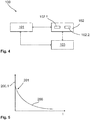
- the household appliance 1 is in particular by a method 100, as in FIG Figure 4 shown in a schematic representation of process steps, operable.
- the household appliance 1 also has an electrical second functional unit 20 for providing a second appliance function for the user.
- the first functional unit 10 can also be driven by a drive device 11, which has an electric motor 12 and a connection 13 for supplying energy to the electric motor 12.
- a series circuit 30 is also connected between the connection 13 and the electric motor 12, which has a current limiting element 31 for limiting a current 200 has.
- the drive device 11 also has a motor controller 14 and a capacity 15 in order to be able to control the electric motor 12.
- the capacitance 15 can preferably be configured as a film capacitor and / or an intermediate circuit capacitor.
- the electric motor 12 is an electric motor operated by a converter, preferably a reluctance motor.
- the motor controller 14 and the capacitance 15 are connected between the connection 13 and the electric motor 12.
- a current 200 from the connection 13 for the electric motor 12 can be buffered by the capacitance 15, the motor controller 14 preferably having one or more power converters.
- a rectifier can be provided if the capacitance 15 is designed as an intermediate circuit capacitor. If the capacity 15 is completely discharged, a charging current could be generated when the capacity 15 is recharged, which has a course as exemplified in FIG Figure 5 shown. In particular, such or similar starting currents can also be caused by the electric motor 12 when starting.
- FIG. 2 shows a profile of a current parameter 200.2 of a current 200, in particular a current intensity, versus time t, which has at least one current peak 201 at the start of switching on. At least the current peak 201 of the current 200 can be limited by the series circuit 30 or by the current limiting element 31, e.g. By reducing or eliminating the current spike 201. As a result, a harmless value of the current parameter 200.2 can be guaranteed during a switch-on process of the household appliance 1.
- the current limiting element 31 is formed by the second functional unit 20 of the household appliance 1.
- at least one area of the second functional unit 20, which at the same time serves to perform the second device function, can also be used as a current limiting element 31.
- the area is electrically connected to the upstream circuit 30 in a detachable or undetachable manner.
- a protective switching state I is shown in which a switching unit 32 of the upstream circuit 30 is switched in such a way that the current 200 flows from the connection 13 to the capacitance 15 and / or to the electric motor 12 via the current limiting element 31 and thus via the second functional unit 20.
- a first switching element 33 which is connected in parallel to the current limiting element 31, is open and a second and a third switching element 34, 35 of the switchover unit 32 are closed.
- the second switching element 34 is connected in series with the current limiting element 31.
- the third switching element 35 is preferably used to connect a further potential of the connection 13 to the capacitance 15 and / or the electric motor 12.
- the drive device 11 in particular the electric motor 12, can be operated 101 by the electric current 200, the current 200 being limited by the second functional unit 20.
- switching 102 of the drive device 11, in particular of the series circuit 30, into an operating switching state II in which the current limiting element 31 is deactivated can be provided.
- a closing 102.1 of the first switching element 33 of the switchover unit 32 and an opening 102.2 of the second switching element 34 can be provided.
- the current limiting element 31 is bridged and electrically isolated from the connection 13 and / or from the electric motor 12, as in FIG Figure 2 shown.
- the capacitance 15 and the electric motor 12 can be operated independently of the current limiting element 31 and the second functional unit 20, so that energy consumption is not influenced by the additional current limitation.
- a switchover 103 to a safety state III can preferably take place, as in FIG Figure 3 shown.
- the first, second and third switching elements 33, 34, 35 are opened in order to achieve complete electrical separation.
- a discharge of the capacitance 15 can be provided in that the electric motor 12 is energized by the motor controller 14 through the capacitance 15 in such a way that a rotor of the electric motor 12 does not rotate.
- FIG. 6 also shows a household appliance 1 in the form of a kitchen appliance 1.1 with a movable first functional unit 10 for providing a first appliance function for a user.
- the first functional unit 10 comprises an agitator, in particular in the form of a rotatable knife, so that ingredients can be comminuted and / or mixed in the kitchen appliance 1.1 as part of the first device function.
- the kitchen appliance 1.1 has an electrical second functional unit 20 for providing a second device function for the user.
- the second functional unit 20 comprises an electrical resistance heater 21, as in FIG Figure 7 shown.
- the first and second functional units 10, 20 are arranged in a cooking vessel 2 of the kitchen appliance 1.1, so that ingredients that are put into the cooking vessel 2 can be processed by the first functional unit 10 and the second functional unit 20.
- the first functional unit 10 and / or the drive device 11 can be passed through a base 2.2 of the cooking vessel 2.
- the second functional unit 20 can preferably be arranged on the bottom 2.2 of the cooking vessel 2.
- the kitchen appliance 1.1 also has a drive device 11 with an electric motor 12, which can be designed according to the first exemplary embodiment.
- the drive device 11 has an upstream circuit 30 with a current limiting element 31 for limiting a current 200, the current limiting element 31 being formed by the second functional unit 20.
- the resistance heater 21 has at least one resistance element 22, which when energized lead to a heating of the resistance heater 21 and thereby the Can heat the ingredients in the cooking vessel 2.
- the resistance element 21 is also connected to the drive device 11 by electrical contact 3, in particular in the form of a plug connection, and is electrically integrated into the upstream circuit 30.
- the resistance element 22 forms the current-limiting element 31 at least in some areas.
- several resistance elements 22 connected to one another can form the current-limiting element 31 in some areas or completely. Due to the electrical contact 3, in particular the plug connection, the cooking vessel 2 with the first and second functional units 10, 20 can be detachable from the drive device 11 and thus z. B. can be used for pouring out the ingredients and / or for cleaning independently of the drive device 11.
- the resistance heater 21 can preferably also have a measuring sensor 23 for measuring a current parameter.
- the measuring sensor 23 can be arranged on the resistance element 21 in such a way that the measuring sensor 23 can measure a current 200 from the upstream circuit 30 at the current limiting element 31 and / or a current flow during operation of the resistance heater 21.
- a maximum capacity of a capacity 15 of the drive device 11 can be determined, and thus in particular their functionality can be checked.
- a sensor that is already present on resistance heater 21 can thus be used.
Landscapes
- Engineering & Computer Science (AREA)
- Power Engineering (AREA)
- Food Science & Technology (AREA)
- Mechanical Engineering (AREA)
- Food-Manufacturing Devices (AREA)
Abstract
Die Erfindung betrifft ein Haushaltsgerät (1) aufweisend eine bewegbare erste Funktionseinheit (10) zum Bereitstellen einer ersten Gerätefunktion für einen Benutzer, eine elektrische zweite Funktionseinheit (20) zum Bereitstellen einer zweiten Gerätefunktion für den Benutzer, und eine Antriebsvorrichtung (11) zum Antreiben der ersten Funktionseinheit (10) mit einem Elektromotor (12), einem Anschluss (13) zur Energieversorgung des Elektromotors (12) und einer Vorschaltung (30), die zwischen den Anschluss (13) und den Elektromotor (12) geschaltet ist, wobei die Vorschaltung (30) ein Strombegrenzungselement (31) zum Begrenzen eines Stroms (200) aufweist.Ferner betrifft die Erfindung ein Verfahren (100) zum Betreiben eines Haushaltsgeräts (1).The invention relates to a household appliance (1) having a movable first functional unit (10) for providing a first device function for a user, an electrical second functional unit (20) for providing a second device function for the user, and a drive device (11) for driving the first functional unit (10) with an electric motor (12), a connection (13) for supplying energy to the electric motor (12) and an upstream circuit (30) which is connected between the connection (13) and the electric motor (12), the upstream circuit (30) has a current limiting element (31) for limiting a current (200). Furthermore, the invention relates to a method (100) for operating a domestic appliance (1).
Description
Die Erfindung betrifft ein Haushaltgerät gemäß dem Oberbegriff des unabhängigen Vorrichtungsanspruchs sowie ein Verfahren zum Betreiben eines Haushaltsgerätes.The invention relates to a household appliance according to the preamble of the independent device claim and a method for operating a household appliance.
Elektrisch betriebene Haushaltsgeräte sind aus dem Stand der Technik bekannt. Dabei wird häufig ein Elektromotor eingesetzt, durch den zum Beispiel ein rotierbares oder translatorisch bewegbares Element des Haushaltsgerätes verstellt wird, um eine bestimmte Funktion des Haushaltsgerätes auszuführen. So sind z. B. Küchenmaschinen bekannt, bei denen die Messer zum Zerkleinern oder durch Mischen von Zutaten durch einen Elektromotor rotatorisch angetrieben werden. Um möglichst viele Funktionen in einem einzigen Gerät zu vereinen, weisen derartige Küchenmaschinen häufig weitere Funktionen auf. Insbesondere beim Einschalten des Elektromotors können jedoch hohe Ströme entstehen, die den Motor und/oder weitere elektrische Komponenten beschädigen können.Electrically operated household appliances are known from the prior art. In this case, an electric motor is often used, by means of which, for example, a rotatable or translationally movable element of the household appliance is adjusted in order to perform a specific function of the household appliance. So are z. B. kitchen machines are known in which the knives for chopping or mixing ingredients are driven in rotation by an electric motor. In order to combine as many functions as possible in a single device, such kitchen machines often have additional functions. However, high currents can occur, particularly when the electric motor is switched on that can damage the motor and / or other electrical components.
Um derartige Anlauf- und/oder Einschaltströme zu begrenzen, ist es ferner bekannt, leistungsstarke Widerstände in Reihe zu solchen elektrischen Komponenten zu schalten, die diese Anlauf- und/oder Einschaltströme verursachen können. So werden teilweise NTC Widerstände eingesetzt, die im kalten Zustand einen hohen Widerstand aufweisen, der den Strom beim Einschalten begrenzt und später mit zunehmender Erwärmung einen niedrigeren Widerstand aufweisen. Dabei ist es jedoch von Nachteil, dass bei einer regelmäßigen und/oder schnellen Folge eines Ein- und Ausschaltens des Elektromotors die Zeit zwischen den Schaltvorgängen gegebenenfalls nicht ausreicht, um den Widerstand abzukühlen und somit wieder den Zustand mit hohem Widerstand einzunehmen. Ferner sind derartige zusätzliche Widerstände oft vibrationsanfällig (da sie häufig ein Keramikgehäuse aufweisen) und können in Folge dynamischer Belastungen eine reduzierte Lebensdauer aufweisen. Darüber hinaus verursachen zusätzliche Widerstände Kosten und benötigen Bauraum.In order to limit such starting and / or inrush currents, it is also known to connect high-performance resistors in series with those electrical components that can cause these inrush and / or inrush currents. In some cases, NTC resistors are used that have a high resistance when cold, which limits the current when switched on and later have a lower resistance as the temperature increases. In this case, however, it is disadvantageous that with a regular and / or rapid sequence of switching the electric motor on and off, the time between the switching processes may not be sufficient to cool the resistance and thus to return to the state with high resistance. Furthermore, such additional resistors are often susceptible to vibration (since they often have a ceramic housing) and can have a reduced service life as a result of dynamic loads. In addition, additional resistors cause costs and require installation space.
Es ist eine Aufgabe der vorliegenden Erfindung, voranstehend aus dem Stand der Technik bekannte Nachteile zumindest teilweise zu beheben. Insbesondere ist es eine Aufgabe der vorliegenden Erfindung die Begrenzung eines Stromes, insbesondere beim Einschalten einer elektrischen Komponente, bei einem Haushaltsgerät in kostengünstiger Art und Weise zu verbessern.It is an object of the present invention to at least partially remedy the disadvantages known from the prior art. In particular, it is an object of the present invention to improve the limitation of a current, in particular when switching on an electrical component, in a household appliance in a cost-effective manner.
Die voranstehende Aufgabe wird gelöst durch ein Haushaltsgerät mit den Merkmalen des unabhängigen Vorrichtungsanspruchs sowie ein Verfahren zum Betreiben eines Haushaltgeräts mit den Merkmalen des unabhängigen Verfahrensanspruchs. Weitere Merkmale und Details der Erfindung ergeben sich aus den Unteransprüchen, der Beschreibung und den Zeichnungen. Dabei gelten Merkmale und Details, die in Zusammenhang mit der erfindungsgemäßen Vorrichtung beschrieben worden sind, selbstverständlich auch in Zusammenhang mit dem erfindungsgemäßen Verfahren und jeweils umgekehrt, sodass bzgl. der Offenbarung zu den einzelnen Erfindungsaspekten stets wechselseitig Bezug genommen wird bzw. werden kann.The above object is achieved by a household appliance with the features of the independent device claim and a method for operating a household appliance with the features of the independent method claim. Further features and details of the invention emerge from the subclaims, the description and the drawings. Features and details that have been described in connection with the device according to the invention naturally also apply in connection with the method according to the invention and in each case vice versa, so that with regard to the disclosure of the individual aspects of the invention, reference is or can always be made to each other.
Erfindungsgemäß weist das Haushaltgerät eine bewegbare erste Funktionseinheit zum Bereitstellen einer ersten Gerätefunktion für einen Benutzer, eine elektrische zweite Funktionseinheit zum Bereitstellen einer zweiten Gerätefunktion für den Benutzer, und eine Antriebsvorrichtung zum Antreiben der ersten Funktionseinheit auf. Die Antriebsvorrichtung weist ferner einen Elektromotor, einen Anschluss zur Energieversorgung des Elektromotors und eine Vorschaltung auf, wobei die Vorschaltung zwischen den Anschluss und den Elektromotor geschaltet ist. Weiterhin weist die Vorschaltung ein Strombegrenzungselement zum Begrenzen eines Stroms (beim Einschalten oder Anlaufen der Antriebsvorrichtung; gemeint ist: während der Zeitspanne) auf. Dabei ist das Strombegrenzungselement durch die zweite Funktionseinheit gebildet. Die Vorschaltung kann insbesondere auch als Vorschalteinheit bezeichnet werden.According to the invention, the household appliance has a movable first functional unit for providing a first device function for a user, an electrical second Functional unit for providing a second device function for the user, and a drive device for driving the first functional unit. The drive device also has an electric motor, a connection for supplying energy to the electric motor and an upstream connection, the upstream connection being connected between the connection and the electric motor. Furthermore, the upstream circuit has a current limiting element for limiting a current (when the drive device is switched on or started up; this means: during the period of time). The current limiting element is formed by the second functional unit. The series connection can in particular also be referred to as a series connection unit.
Unter dem Begrenzen des Stroms kann insbesondere ein Begrenzen einer Stromspitze, eines Einschaltstroms und/oder eines Anlaufstroms verstanden werden. Vorzugsweise kann beim Begrenzen des Stroms ein Stromparameter insbesondere auf einen unschädlichen Wert reduziert werden. Dabei kann das Strombegrenzungselement derart zum Elektromotor geschaltet sein, dass das Strombegrenzungselement einen Anlaufwiderstand für den Elektromotor bildet. Insbesondere ist das Strombegrenzungselement in Reihe zum Elektromotor und/oder zum Anschluss geschaltet. Vorzugsweise kann die Vorschaltung dazu ausgebildet sein, den Strom temporär zu begrenzen, z. B. indem das Strombegrenzungselement aktivierbar und/oder deaktivierbar ist. Unter dem Anschluss kann insbesondere ein elektrischer Anschluss zum Anschluss an ein Stromnetz und/oder an einen Energiespeicher, wie z. B. eine Batterie, verstanden werden. Dabei kann der Anschluss auch permanent mit dem Stromnetz und/oder dem Energiespeicher während des Betriebs des Haushaltsgerätes verbunden sein. Unter der ersten und/oder der zweiten Gerätefunktion kann insbesondere ein Hauptnutzen des Haushaltgerätes verstanden werden. Insbesondere wird durch die erste Funktion ein erster Nutzen (bspw. Rühren und/oder Häckseln) für den Benutzer durch das Haushaltgerät bereitgestellt und durch die zweite Gerätefunktion ein zweiter Nutzen (bspw. Erwärmen und/oder Kochen). Die erste und zweite Gerätefunktion können voneinander unabhängige Gerätefunktionen sein. Die gesamte zweite Funktionseinheit kann das Strombegrenzungselement bilden oder ein Teil der zweiten Funktionseinheit kann das Strombegrenzungselement bilden.Limiting the current can in particular mean limiting a current peak, an inrush current and / or a starting current. When limiting the current, a current parameter can preferably be reduced in particular to a harmless value. The current limiting element can be connected to the electric motor in such a way that the current limiting element forms a starting resistor for the electric motor. In particular, the current limiting element is connected in series to the electric motor and / or to the connection. The upstream circuit can preferably be designed to temporarily limit the current, e.g. B. by the current limiting element can be activated and / or deactivated. Under the connection, in particular, an electrical connection for connection to a power grid and / or to an energy store, such as. B. a battery can be understood. The connection can also be permanently connected to the power grid and / or the energy store while the household appliance is in operation. The first and / or the second device function can be understood to mean, in particular, a main use of the household device. In particular, the first function provides a first benefit (for example stirring and / or chopping) for the user by the household appliance, and the second device function provides a second benefit (e.g. heating and / or cooking). The first and second device functions can be device functions that are independent of one another. The entire second functional unit can form the current limiting element or part of the second functional unit can form the current limiting element.
Dadurch, dass das Strombegrenzungselement durch die zweite Funktionseinheit gebildet ist, kann ein zusätzlicher Nutzen der zweiten Funktionseinheit generiert werden, indem diese zum einen zum Bereitstellen der zweiten Gerätefunktion dient und zum anderen als Strombegrenzungselement. Dabei kann vorgesehen sein, dass die zweite Funktionseinheit nur temporär das Strombegrenzungselement bildet und elektrisch von der Vorschaltung getrennt wird, wenn ein Begrenzen des Stroms, z. B. nach dem Einschalten, nicht mehr notwendig ist. Insbesondere kann ein zusätzlicher Vorwiderstand, insbesondere in Form eines zusätzlichen Bauteils, entfallen, sodass diesbezügliche Kosten sowie Bauraum eingespart werden können. Insbesondere ist das Haushaltsgerät dadurch ferner robust ausgebildet, denn durch Einsparung eines zusätzlichen Widerstandsbauteils entfällt auch eine weitere Schwachstelle, die z. B. bei Auftreten von Vibrationen (bspw. Bruch der Keramik vom Widerstand) beschädigt werden könnte.Because the current limiting element is formed by the second functional unit, an additional benefit of the second functional unit can be generated in that it serves on the one hand to provide the second device function and on the other hand as a current limiting element. It can be provided that the second functional unit only temporarily forms the current limiting element and is electrically disconnected from the upstream circuit when limiting the current, e.g. B. after switching on, is no longer necessary. In particular, an additional series resistor, in particular in the form of an additional component, can be omitted, so that related costs and installation space can be saved. In particular, the household appliance is also made robust, because by saving an additional resistance component, another weak point is eliminated, the z. B. in the event of vibrations (e.g. breakage of the ceramic from the resistor) could be damaged.
Vorzugsweise kann die zweite Funktionseinheit ferner einen Messsensor zum Messen eines Stromparameters aufweisen. Der Messsensor kann dabei derart mit dem Strombegrenzungselement verbunden sein, dass durch den Messsensor der Strom der Vorschaltung am Strombegrenzungselement und/oder eine Bestromung im Betrieb der zweiten Funktionseinheit messbar ist. Durch eine Messung des Stroms der Vorschaltung kann z. B. eine maximale Kapazität einer Kapazität der Antriebsvorrichtung ermittelt werden, und damit insbesondere deren Funktionsfähigkeit und/oder Ladezustand überprüft werden. Insbesondere kann somit auf einen ohnehin an der zweiten Funktionseinheit vorhandenen Sensor zurückgegriffen werden. Insbesondere können weitere Überwachungsfunktionen der zweiten Funktionseinheit auch auf das Strombegrenzungselement und/oder die Antriebsvorrichtung übertragbar sein bzw. doppelt nutzbar sein. Der Stromparameter kann insbesondere eine elektrische Spannung und/oder eine Stromstärke umfassen. Anhand des ermittelten Ladezustand der Kapazität kann auch der Umschaltzeitpunkt von einem Schutzschaltzustand I (beim Einschalten oder Anlaufen) auf einen Betriebsschaltzustand II (normaler Betrieb der ersten Funktionseinheit nach dem Einschalten oder Anlaufen) (siehe Definitionen der Zustände I/II weiter unten) ermittelt werden.The second functional unit can preferably also have a measuring sensor for measuring a current parameter. The measuring sensor can be connected to the current limiting element in such a way that the measuring sensor can measure the current of the upstream circuit at the current limiting element and / or a current flow during operation of the second functional unit. By measuring the current of the ballast, z. B. a maximum capacity of a capacity of the drive device can be determined, and thus in particular their functionality and / or state of charge are checked. In particular, a sensor which is already present on the second functional unit can thus be used. In particular, further monitoring functions of the second functional unit can also be transferable to the current limiting element and / or the drive device or can be used twice. The current parameter can in particular include an electrical voltage and / or a current intensity. On the basis of the determined state of charge of the capacity, the time of switching from a protective switching state I (when switching on or starting up) to an operating switching state II (normal operation of the first functional unit after switching on or starting up) (see definitions of states I / II below) can also be determined.
Weiterhin ist es im Rahmen der Erfindung denkbar, dass die Antriebsvorrichtung eine über den Anschluss aufladbare Kapazität umfasst, wobei das Strombegrenzungselement zum Begrenzen des Stroms beim Aufladen der Kapazität ausgebildet ist, insbesondere wobei es sich bei der Kapazität um einen Zwischenkreiskondensator handelt. Insbesondere kann das Strombegrenzungselement als Vorladewiderstand ausgebildet sein. Vorzugsweise kann die Kapazität ferner einen Folienkondensator und/oder Elektrolytkondensator aufweisen. Wenn es sich bei der Kapazität um zumindest einen Zwischenkreiskondensator handelt, kann ferner die Antriebsvorrichtung einen Gleichrichter aufweisen, über den der Elektromotor bestrombar und/oder ansteuerbar ist. Die Kapazität kann eine elektrische Komponente darstellen, welche einen hohen Ladestrom zumindest temporär aufweist. So kann sich insbesondere eine Kapazität in Form eines Zwischenkreiskondensators wie ein Kurzschluss verhalten, wenn diese völlig entladen ist. Insbesondere wenn es sich bei der ersten bewegbaren Funktionseinheit um einen sicherheitsrelevante Funktionseinheit handelt, kann es jedoch wünschenswert sein, die aufladbare Kapazität vollständig zu entladen, wenn der Motor gestoppt wird. Insbesondere in Verbindung mit einer vollständigen Entkopplung von einer Energiequelle kann dadurch sichergestellt werden, dass der Motor nicht auf Grund einer Fehlfunktion auslöst und somit die sicherheitsrelevante Funktion ausgeführt wird, wenn ein Benutzer dies nicht erwartet. Dies kann beispielsweise bei einem Küchengerät der Fall sein, welches ein Rührwerk und/oder einen Mixer aufweist und dessen Elektromotor eine aufladbare Kapazität benötigt. Durch die Ausgestaltung des Kondensators als Folienkondensator und/oder Elektrolytkondensator kann die Robustheit der Vorrichtung weiter gesteigert sein. So sind derartige Kondensatoren z. B. über einen weiten Temperaturbereich temperaturfest und weisen eine hohe Zuverlässigkeit auf.Furthermore, it is conceivable within the scope of the invention that the drive device comprises a capacitance that can be charged via the connection, the current limiting element being designed to limit the current when the capacitance is charged, in particular the capacitance being an intermediate circuit capacitor. In particular, the current limiting element can be designed as a precharge resistor. Preferably the Capacitance furthermore have a film capacitor and / or electrolytic capacitor. If the capacitance is at least one intermediate circuit capacitor, the drive device can furthermore have a rectifier via which the electric motor can be energized and / or controlled. The capacitance can represent an electrical component which has a high charging current at least temporarily. In particular, a capacitance in the form of an intermediate circuit capacitor can behave like a short circuit when it is completely discharged. In particular if the first movable functional unit is a safety-relevant functional unit, however, it may be desirable to completely discharge the chargeable capacity when the engine is stopped. In particular in connection with a complete decoupling from an energy source it can be ensured that the motor does not trigger due to a malfunction and thus the safety-relevant function is carried out if a user does not expect this. This can be the case, for example, with a kitchen appliance which has an agitator and / or a mixer and whose electric motor requires a chargeable capacity. The robustness of the device can be further increased by designing the capacitor as a film capacitor and / or electrolytic capacitor. Such capacitors are such. B. temperature resistant over a wide temperature range and have a high reliability.
Weiterhin kann bei einem erfindungsgemäßen Haushaltgerät vorgesehen sein, dass die zweite Funktionseinheit eine elektrische Widerstandsheizung umfasst, wobei das Strombegrenzungselement durch zumindest einen Bereich eines Widerstandselements zum Erwärmen der Widerstandsheizung gebildet ist. Das Widerstandselement kann z. B. einen Draht und/oder eine Leiterbahn umfassen, und sich bei Bestromung erwärmen. Das Widerstandselement kann zumindest bereichsweise in die Vorschaltung einbindbar sein, indem dieses z. B. mit der Vorschaltung verschaltet ist oder verschaltbar ist. Die elektrische Widerstandsheizung kann z. B. in einem Küchengerät zum Erwärmen von Speisen dienen oder in dem Haushaltsgerät eine andere Temperaturfunktion ausführen. Insbesondere kann das Erwärmen der Widerstandsheizung durch das Widerstandselement die zweite Gerätefunktion darstellen. Das Widerstandselement kann dabei bereichsweise oder vollständig das Strombegrenzungselement bilden. Insbesondere können mehrere, miteinander verschaltete Widerstandselemente bereichsweise oder vollständig das Strombegrenzungselement bilden. Durch die elektrische Widerstandsheizung können somit die Voraussetzungen vorliegen, die zweite Funktionseinheit, insbesondere ohne signifikante konstruktive Veränderung der zweiten Funktionseinheit, als Strombegrenzungselement in die Vorschaltung einzubinden. Gleichzeitig stellt die elektrische Widerstandsheizung ein robustes Element dar, welches in kostengünstiger und einfacher Art und Weise als Strombegrenzungselement genutzt werden kann.Furthermore, it can be provided in a household appliance according to the invention that the second functional unit comprises an electrical resistance heater, the current-limiting element being formed by at least one area of a resistance element for heating the resistance heater. The resistance element can, for. B. comprise a wire and / or a conductor track, and heat up when energized. The resistance element can be at least partially incorporated into the upstream circuit by this z. B. is or can be interconnected with the upstream connection. The electrical resistance heating can, for. B. serve in a kitchen appliance for heating food or perform a different temperature function in the household appliance. In particular, the heating of the resistance heater by the resistance element can represent the second device function. The resistance element can form the current limiting element in some areas or completely. In particular, several resistance elements connected to one another can form the current limiting element in some areas or completely. The electrical resistance heating can thus the prerequisites exist to integrate the second functional unit, in particular without significant structural changes to the second functional unit, as a current limiting element in the upstream circuit. At the same time, the electrical resistance heater is a robust element which can be used as a current limiting element in a cost-effective and simple manner.
Vorzugsweise kann bei einem erfindungsgemäßen Haushaltsgerät die Vorschaltung eine Umschalteinheit umfassen, durch welche die Vorschaltung zumindest zwischen einem Schutzschaltzustand I, in welchem ein Strom durch das Strombegrenzungselement begrenzbar ist (beim Einschalten oder Anlaufen), und einem (zeitlich folgenden) Betriebsschaltzustand II, in welchem das Strombegrenzungselement deaktiviert ist (im normalen Betrieb), umschaltbar ist. Darunter, dass das Strombegrenzungselement im Betriebsschaltzustand deaktiviert ist, kann insbesondere verstanden werden, dass das Strombegrenzungselement überbrückt und/oder vom Anschluss und/oder vom Elektromotor elektrisch getrennt ist. Somit kann das Strombegrenzungselement deaktiviert werden, wenn eine Stromspitze abgeklungen ist oder die Gefahr eines Auftretens einer Stromspitze oder eines hohen Stroms nicht mehr besteht. Dadurch wird Energie, die am Anschluss bereitgestellt wird, dem Motor zur Verfügung gestellt und wird nicht dem Strombegrenzungselement zugeführt. Somit kann ein energieeffizienter Betrieb des Haushaltsgerätes gewährleistet werden und die erste und zweite Funktionseinheit können elektrisch voneinander entkoppelt werden, wenn eine Strombegrenzung nicht mehr gewünscht wird.In a household appliance according to the invention, the upstream connection can preferably comprise a switching unit, through which the upstream connection at least between a protective switching state I, in which a current can be limited by the current limiting element (when switching on or starting), and an (chronologically following) operating switching state II, in which the Current limiting element is deactivated (in normal operation), is switchable. The fact that the current limiting element is deactivated in the operating switching state can in particular be understood to mean that the current limiting element is bridged and / or is electrically separated from the connection and / or from the electric motor. The current-limiting element can thus be deactivated when a current peak has subsided or the risk of a current peak or a high current no longer occurring. As a result, energy that is provided at the connection is made available to the motor and is not fed to the current limiting element. An energy-efficient operation of the household appliance can thus be guaranteed and the first and second functional units can be electrically decoupled from one another if current limitation is no longer desired.
Weiterhin kann bei einem erfindungsgemäßen Haushaltsgerät vorgesehen sein, dass die Umschalteinheit zum Umschalten zwischen dem Schutzschaltzustand und dem Betriebsschaltzustand zumindest ein erstes Schaltelement, das zum Strombegrenzungselement parallelgeschaltet ist, und ein zweites Schaltelement, das zum Strombegrenzungselement in Reihe geschaltet ist, umfasst. Durch das erste Schaltelement, das zum Strombegrenzungselement parallelgeschaltet ist, kann ein Strompfad gebildet sein, durch welchen das Strombegrenzungselement überbrückbar ist. Durch das zweite Schaltelement, das zum Strombegrenzungselement in Reihe geschaltet ist, kann das Strombegrenzungselement vom Anschluss und/oder von dem Elektromotor elektrisch getrennt werden. Dadurch fließt beim Öffnen des zweiten Schaltelementes kein Strom durch das Strombegrenzungselement und eine elektrische Entkopplung der ersten und zweiten Funktionseinheit kann realisiert werden. Das erste und/oder zweite Schaltelement kann Software- und/oder Hardware-gestützt schaltbar sein. Somit kann durch die Umschalteinheit eine robuste Möglichkeit geschaffen sein zwischen dem Schutzschaltzustand und dem Betriebsschaltzustand umzuschalten und das Strombegrenzungselement in zuverlässiger Art und Weise elektrisch zu trennen. Ferner kann beim Öffnen des ersten und zweiten Schaltelementes eine vollständige elektrische Trennung des Motors und/oder Kondensators von einer Energiequelle realisiert sein. Vorzugsweise kann die Umschalteinheit ein drittes Schaltelement aufweisen, durch welches der Sicherheitszustand erreicht werden kann, wenn das erste, zweite und dritte Schaltelement geöffnet sind. Dadurch kann eine vollständige Trennung des Elektromotors und/oder des Kondensators vom Anschluss und/oder vom Strombegrenzungselement erreicht werden. Insbesondere kann das dritte Schaltelement derart in der Vorschaltung angeordnet sein, dass durch Öffnen des dritten und des ersten und/oder zweiten Schaltelementes zwei unterschiedliche Potentiale vom Elektromotor und/oder Kondensator getrennt werden. Durch die Möglichkeit der elektrischen Trennung des Anschlusses kann die Sicherheit und Zuverlässigkeit des Haushaltsgerätes verbessert sein.Furthermore, it can be provided in a household appliance according to the invention that the switching unit for switching between the protective switching state and the operating switching state comprises at least one first switching element, which is connected in parallel to the current limiting element, and a second switching element, which is connected in series with the current limiting element. The first switching element, which is connected in parallel with the current limiting element, can form a current path through which the current limiting element can be bridged. By means of the second switching element, which is connected in series with the current limiting element, the current limiting element can be electrically isolated from the connection and / or from the electric motor. As a result, no current flows through when the second switching element is opened the current limiting element and an electrical decoupling of the first and second functional unit can be realized. The first and / or second switching element can be switchable with software and / or hardware support. The switchover unit can thus create a robust possibility of switching between the protective switching state and the operating switching state and of electrically isolating the current-limiting element in a reliable manner. Furthermore, when the first and second switching elements are opened, the motor and / or capacitor can be completely electrically isolated from an energy source. The switchover unit can preferably have a third switching element, by means of which the safety state can be achieved when the first, second and third switching elements are open. As a result, a complete separation of the electric motor and / or the capacitor from the connection and / or from the current limiting element can be achieved. In particular, the third switching element can be arranged in the upstream circuit in such a way that, by opening the third and the first and / or second switching element, two different potentials are separated from the electric motor and / or capacitor. The possibility of electrical separation of the connection can improve the safety and reliability of the household appliance.
Im Rahmen der Erfindung kann ferner vorgesehen sein, dass die Umschalteinheit zum Umschalten zwischen dem Schutzschaltzustand und dem Betriebsschaltzustand zumindest ein Relais und/oder zumindest einen Transistor, insbesondere in Form eines MOSFETs, aufweist. Vorzugsweise kann das erste und/oder zweite Schaltelement als Relais und/oder Transistor, insbesondere in Form eines MOSFETs, ausgestaltet sein. Dabei handelt es sich um kostengünstige, robuste Bauteile. Unter einem MOSFET kann insbesondere ein Metall-Oxyd-Halbleiter-Feldeffekttransistor verstanden werden durch welchen in zuverlässiger Art und Weise kurze Schaltzeiten und hohe Schaltzahlen erzielt werden können. Dadurch kann somit ein zuverlässiger Betrieb des Haushaltsgerätes gewährleistet sein. Durch die elektromagnetische Verstellmöglichkeit des Relais ist dieses ferner in einfacher Art und Weise ansteuerbar und zuverlässig. Insbesondere kann durch den Einsatz eines Relais die Komplexität einer Steuerung deutlich reduziert sein. Auch das dritte Schaltelement kann als Relais als Relais und/oder Transistor, insbesondere in Form eines MOSFETs, ausgestaltet sein.In the context of the invention it can furthermore be provided that the switching unit has at least one relay and / or at least one transistor, in particular in the form of a MOSFET, for switching between the protective switching state and the operating switching state. The first and / or second switching element can preferably be configured as a relay and / or transistor, in particular in the form of a MOSFET. These are inexpensive, robust components. A MOSFET can in particular be understood to mean a metal-oxide-semiconductor field effect transistor by means of which short switching times and high switching numbers can be achieved in a reliable manner. Reliable operation of the household appliance can thus be guaranteed. Due to the electromagnetic adjustment possibility of the relay, it can also be controlled in a simple manner and is reliable. In particular, the use of a relay can significantly reduce the complexity of a controller. The third switching element can also be designed as a relay as a relay and / or transistor, in particular in the form of a MOSFET.
Weiterhin kann bei einem erfindungsgemäßen Haushaltsgerät vorgesehen sein, dass zwischen die Vorschaltung und den Elektromotor eine Motorsteuereinheit zum Ansteuern des Elektromotors geschaltet ist, insbesondere wobei es sich bei dem Elektromotor um einen umrichterbetriebenen Motor handelt. Insbesondere kann durch einen umrichterbetriebenen Motor eine zuverlässige, robuste Ausgestaltung erzielt werden. Durch die Motorsteuereinheit kann insbesondere eine hohe Leistung des Motors abgerufen werden. Weiterhin kann durch die Motorsteuereinheit ein Elektromotor eingesetzt werden, der wartungsarm oder wartungsfrei ist. Vorzugsweise kann es sich bei dem Elektromotor um einen bürstenlosen Motor, insbesondere eine Reluktanzmotor, handeln. Dadurch kann die Robustheit des Haushaltsgerätes weiter gesteigert sein. Durch die Vorschaltung können ferner empfindliche elektrische Bauteile der Motorsteuereinheit vor hohen Strömen geschützt werden, die insbesondere auch dann auftreten können, wenn der umrichterbetriebene Motor in einem hohen Leistungsbereich angesteuert werden soll. Um den umrichterbetriebenen Motor anzusteuern, kann die Motorsteuerung vorzugsweise einen oder mehrere Stromrichter aufweisen. Ferner kann die Motorsteuerung dazu ausgebildet sein drei oder mehr Phasen des Elektromotors anzusteuern. Somit kann die Motorsteuerung ein elektronisches Bauteil darstellen, welches durch einen hohen Strom beschädigt werden könnte, so dass die robuste Realisierung des Strombegrenzungselementes durch die zweite Funktionseinheit die Motorsteuereinheit schützen kann.Furthermore, it can be provided in a household appliance according to the invention that a motor control unit for controlling the electric motor is connected between the upstream circuit and the electric motor, in particular the electric motor being a converter-operated motor. In particular, a converter-operated motor can be used to achieve a reliable, robust design. The engine control unit can, in particular, call up high engine power. Furthermore, the motor control unit can use an electric motor that is low-maintenance or maintenance-free. The electric motor can preferably be a brushless motor, in particular a reluctance motor. This can further increase the robustness of the household appliance. The upstream connection can also protect sensitive electrical components of the motor control unit from high currents, which can also occur in particular when the converter-operated motor is to be controlled in a high power range. In order to control the converter-operated motor, the motor control can preferably have one or more power converters. Furthermore, the motor controller can be designed to control three or more phases of the electric motor. The engine control can thus represent an electronic component which could be damaged by a high current, so that the robust implementation of the current limiting element by the second functional unit can protect the engine control unit.
Weiterhin kann bei einem erfindungsgemäßen Haushaltsgerät vorgesehen sein, dass es sich bei dem Haushaltsgerät um ein Küchengerät zum Zubereiten von Speisen handelt, insbesondere wobei die erste Funktionseinheit ein Rührwerk aufweist und/oder wobei die zweite Funktionseinheit in einem von der Antriebsvorrichtung lösbaren Kochgefäß angeordnet ist. In dem Küchengerät kann z. B. eine elektrische Widerstandsheizung vorgesehen sein, die die zweite Funktionseinheit bildet und zum Erwärmen von Speisen vorgesehen ist. Das Rührwerk kann zum Umrühren und/oder Zerkleinern von Zutaten ausgebildet sein. Insbesondere kann das Rührwerk ein Rührmittel, insbesondere in Form eines rotierbaren Messer, aufweisen. Somit können diverse Arbeitsschritte beim Zubereiten von Speisen durch das Haushaltsgerät durchgeführt werden, wobei die zweite Funktionseinheit effizient genutzt werden kann, wenn diese gleichzeitig das Strombegrenzungselement bildet. Ist die zweite Funktionseinheit lösbar von der Antriebsvorrichtung in einem Kochgefäß angeordnet, kann dieses in einfacher Art und Weise durch den Benutzer gereinigt werden und insbesondere im mit der Antriebsvorrichtung verbundenen Zustand das Strombegrenzungselement bilden.Furthermore, it can be provided in a household appliance according to the invention that the household appliance is a kitchen appliance for preparing food, in particular wherein the first functional unit has an agitator and / or wherein the second functional unit is arranged in a cooking vessel that can be detached from the drive device. In the kitchen appliance, for. B. an electrical resistance heater can be provided, which forms the second functional unit and is provided for heating food. The agitator can be designed for stirring and / or comminuting ingredients. In particular, the agitator can have a stirring means, in particular in the form of a rotatable knife. Various work steps can thus be carried out by the household appliance when preparing food, with the second functional unit being able to be used efficiently if it simultaneously forms the current limiting element. If the second functional unit is arranged detachably from the drive device in a cooking vessel, this can be done in a simple manner be cleaned by the user and in particular form the current limiting element in the state connected to the drive device.
Ferner kann bei einem erfindungsgemäßen Haushaltsgerät vorgesehen sein, dass die zweite Funktionseinheit mit der Antriebsvorrichtung, insbesondere mit der Vorschaltung, durch eine elektrische Kontaktierung, vorzugsweise in Form einer Steckverbindung, verbunden ist, wodurch die zweite Funktionseinheit von der Antriebsvorrichtung, d.h. insbesondere aus der Antriebsvorrichtung, lösbar ist. Durch die Steckverbindung kann in einfacher Art und Weise eine Möglichkeit geschaffen sein die zweite Funktionseinheit zum einen elektrisch von der Antriebsvorrichtung und vom elektrischen Anschluss zu entkoppeln und zum anderen die zweite Funktionseinheit unabhängig von der Antriebsvorrichtung zu nutzen. Dadurch kann die zweite Funktionseinheit z. B. in einem Kochgefäß angeordnet sein, das in einer Spülmaschine gereinigt werden kann. Somit kann ein Komfort des Haushaltsgeräts erhöht werden, ohne dass das Haushaltsgerät für den täglichen Einsatz weniger robust wird. Die Steckverbindung kann insbesondere einen Stecker und eine Buchse aufweisen, insbesondere wobei der Stecker an der zweiten Funktionseinheit und die Buchse an der Antriebsvorrichtung angeordnet sein kann oder umgekehrt. Zusätzlich oder alternativ kann die elektrische Kontaktierung zwei offenliegende elektrische Kontakte aufweisen, welche bei gegenseitiger Kontaktierung eine elektrische Verbindung bereitstellen.Furthermore, it can be provided in a household appliance according to the invention that the second functional unit is connected to the drive device, in particular to the upstream circuit, by means of electrical contacting, preferably in the form of a plug connection, whereby the second functional unit is connected to the drive device, i.e. in particular from the drive device, is detachable. The plug connection provides a simple way of decoupling the second functional unit on the one hand electrically from the drive device and from the electrical connection and on the other hand using the second functional unit independently of the drive device. This allows the second functional unit z. B. be arranged in a cooking vessel that can be cleaned in a dishwasher. The convenience of the household appliance can thus be increased without the household appliance becoming less robust for daily use. The plug connection can in particular have a plug and a socket, in particular wherein the plug can be arranged on the second functional unit and the socket on the drive device or vice versa. Additionally or alternatively, the electrical contacting can have two exposed electrical contacts, which provide an electrical connection when they make contact with one another.
Gemäß einem weiteren Aspekt der vorliegenden Erfindung ist ein Verfahren zum Betreiben eines Haushaltsgerätes, insbesondere eines erfindungsgemäßen Haushaltsgerätes, beansprucht. Das Haushaltsgerät weist dabei eine bewegbare erste Funktionseinheit zum Bereitstellen einer ersten Gerätefunktion für einen Benutzer auf. Das Verfahren umfasst zumindest folgenden Schritt:
- Betreiben einer Antriebsvorrichtung zum Antreiben der ersten Funktionseinheit des Haushaltsgerätes durch einen elektrischen Strom, wobei ein Begrenzen des Stroms (insbesondere beim Einschalten oder Anlaufen der Antriebsvorrichtung) durch eine zweite Funktionseinheit des Haushaltsgerätes, die zum Bereitstellen einer zweiten Gerätefunktion für den Benutzer ausgebildet ist, erfolgt.
- Operating a drive device for driving the first functional unit of the household appliance with an electric current, the current being limited (in particular when the drive device is switched on or started up) by a second functional unit of the household appliance, which is designed to provide a second device function for the user.
Damit bringt ein erfindungsgemäßes Verfahren die gleichen Vorteile mit sich, wie sie ausführlich mit Bezug auf ein erfindungsgemäßes Haushaltsgerät beschrieben worden sind.A method according to the invention thus has the same advantages as have been described in detail with reference to a household appliance according to the invention.
Insbesondere kann das Betreiben der Antriebsvorrichtung (ausschließlich) während eines Einschaltens oder Anlaufens (a) des Haushaltsgerätes und/oder (b) eines Elektromotors der Antriebsvorrichtung und/oder während eines Aufladens (c) eines Kondensators, der dem Elektromotor vorgeschaltet ist, durchgeführt werden. Das Betreiben der Antriebsvorrichtung kann somit insbesondere ein Starten und/oder Antreibens des Elektromotors umfassen.In particular, the drive device can be operated (exclusively) during switching on or starting (a) the household appliance and / or (b) an electric motor of the drive device and / or during charging (c) a capacitor that is connected upstream of the electric motor. The operation of the drive device can thus in particular include starting and / or driving the electric motor.
Vorzugsweise kann ein Messen eines Stromparameters des Stroms durch die zweite Funktionseinheit, insbesondere einen Messsensor der zweiten Funktionseinheit erfolgen. Insbesondere kann dabei der Strom an der Antriebsvorrichtung, insbesondere einer Vorschaltung der Antriebsvorrichtung, und/oder eine Bestromung im Betrieb der zweiten Funktionseinheit gemessen werden. Anhand der Messung des Stroms der Vorschaltung kann vorgesehen sein, dass z. B. eine maximale Kapazität einer Kapazität der Antriebsvorrichtung ermittelt wird, und damit insbesondere deren Funktionsfähigkeit überprüft wird. Insbesondere kann somit auf einen ohnehin an der zweiten Funktionseinheit vorhandenen Sensor zurückgegriffen werden. Insbesondere können weitere Überwachungsfunktionen der zweiten Funktionseinheit auch auf das Strombegrenzungselement und/oder die Antriebsvorrichtung übertragbar sein bzw. doppelt nutzbar sein.A current parameter of the current can preferably be measured by the second functional unit, in particular a measuring sensor of the second functional unit. In particular, the current at the drive device, in particular an upstream connection of the drive device, and / or a current flow during operation of the second functional unit can be measured. Based on the measurement of the current of the upstream circuit it can be provided that, for. B. a maximum capacity of a capacity of the drive device is determined, and thus in particular their functionality is checked. In particular, a sensor which is already present on the second functional unit can thus be used. In particular, further monitoring functions of the second functional unit can also be transferable to the current limiting element and / or the drive device or can be used twice.
Weiterhin kann bei einem erfindungsgemäßen Verfahren vorgesehen sein, dass zumindest beim Betreiben der Antriebsvorrichtung eine Kapazität des Haushaltgerätes geladen wird, wobei beim Begrenzen des Stroms ein Ladestrom der Kapazität begrenzt wird. Insbesondere kann es sich somit bei dem Strom, welcher begrenzt wird, um den Ladestrom handeln. Die Kapazität kann dazu eingesetzt werden, einen Strom für einen Elektromotor zu puffern. Kritisch kann dabei ein Aufladen der Kapazität sein, wenn die Kapazität vollständig entladen ist. Dies kann bspw. der Fall sein, nachdem ein Umschalten in den Sicherheitszustand durchgeführt wurde. Zwar ist im Sicherheitszustand die Sicherheit der ersten Funktionseinheit gewährleistet, jedoch entsteht bei erneutem Aufladen der Kapazität ggf. ein hoher Strom. Dieser kann durch die zweite Funktionseinheit begrenzt werden.Furthermore, it can be provided in a method according to the invention that a capacity of the household appliance is charged at least when the drive device is operated, with a charging current of the capacity being limited when the current is limited. In particular, the current that is limited can thus be the charging current. The capacity can be used to buffer a current for an electric motor. Charging of the capacity can be critical when the capacity is completely discharged. This can be the case, for example, after a switchover to the safety state has been carried out. Although the safety of the first functional unit is guaranteed in the safety state, a high current may arise when the capacity is recharged. This can be limited by the second functional unit.
Weiterhin kann bei einem erfindungsgemäßen Verfahren vorgesehen sein, dass das Begrenzen des Stroms in einem Schutzschaltzustand der Antriebsvorrichtung, insbesondere einer Vorschaltung der Antriebsvorrichtung, erfolgt, und das Verfahren zumindest einen der folgenden Schritte umfasst:
- Umschalten in einen Betriebsschaltzustand der Antriebsvorrichtung, insbesondere der Vorschaltung, in welchem das Begrenzen des Stroms durch die zweite Funktionseinheit deaktiviert ist, und/oder
- Umschalten in einem Sicherheitszustand der Antriebsvorrichtung, insbesondere der Vorschaltung, in welchem ein Elektromotor der Antriebsvorrichtung von einem Anschluss der Antriebsvorrichtung elektrisch getrennt ist.
- Switching to an operating switching state of the drive device, in particular the upstream connection, in which the limiting of the current through the second functional unit is deactivated, and / or
- Switching in a safety state of the drive device, in particular the upstream connection, in which an electric motor of the drive device is electrically separated from a connection of the drive device.
Durch das Umschalten in den Betriebsschaltzustand fließt insbesondere kein Strom des Elektromotors über das Strombegrenzungselement bzw. über die zweite Funktionseinheit. Dadurch können die erste und zweite Funktionseinheit im Betriebsschaltzustand elektrisch getrennt sein und unabhängig voneinander betrieben werden. Insbesondere erfolgt im Betriebsschaltzustand ein Antreiben der ersten Funktionseinheit durch den Elektromotor. Durch die Deaktivierung des Strombegrenzungselementes ist somit auch der Widerstand vom Anschluss zum Elektromotor reduziert, sodass im normalen Betrieb des Elektromotors die Verluste reduziert sein können. Beim Umschalten der Vorschaltung in den Sicherheitszustand wird vorzugsweise der Elektromotor vollständig vom Anschluss elektrisch getrennt. Vorzugsweise wird dies durch Öffnen eines oder mehrerer Schaltelemente, insbesondere einer Umschalteinheit der Vorschaltung, durchgeführt. Ferner kann im Sicherheitszustand ein Entladen einer Kapazität der Antriebsvorrichtung, vorzugsweise über den Elektromotor, erfolgen. Somit kann der Elektromotor im Sicherheitszustand über die Motorsteuerung derart bestromt werden, dass sich ein Rotor des Elektromotors nicht dreht. So können beispielsweise die Phasen des Elektromotors entsprechend angesteuert werden, sodass sich der Rotor nicht bewegt, eine im Kondensator noch vorhandene Spannung jedoch abgebaut wird. Dadurch kann im Sicherheitszustand ein unbeabsichtigtes Einschalten des Elektromotors vermieden werden. Im Betriebsschaltzustand kann insbesondere ein Normalbetrieb der ersten und/oder zweiten Funktionseinheit ermöglicht sein und/oder ausgeführt werden.By switching to the operating switching state, in particular no current from the electric motor flows via the current limiting element or via the second functional unit. As a result, the first and second functional units can be electrically separated in the operating state and operated independently of one another. In particular, in the operating switching state, the first functional unit is driven by the electric motor. Deactivating the current limiting element also reduces the resistance from the connection to the electric motor, so that the losses can be reduced during normal operation of the electric motor. When switching the upstream connection to the safety state, the electric motor is preferably completely electrically disconnected from the connection. This is preferably carried out by opening one or more switching elements, in particular a switchover unit of the upstream circuit. Furthermore, in the safety state, a capacity of the drive device can be discharged, preferably via the electric motor. Thus, in the safety state, the electric motor can be energized via the motor control in such a way that a rotor of the electric motor does not rotate. For example, the phases of the electric motor can be controlled accordingly so that the rotor does not move, but any voltage that is still present in the capacitor is reduced. In this way, unintentional switching on of the electric motor can be avoided in the safety state. In the operating switching state, normal operation of the first and / or second functional unit can in particular be enabled and / or carried out.
Vorzugsweise kann bei einem erfindungsgemäßen Verfahren vorgesehen sein, dass beim Umschalten in den Betriebsschaltzustand die zweite Funktionseinheit zumindest teilweise überbrückt und/oder vom Anschluss und/oder vom Elektromotor elektrisch getrennt wird.In a method according to the invention, it can preferably be provided that the second functional unit is at least partially bridged and / or electrically isolated from the connection and / or from the electric motor when switching to the operating switching state.
Dadurch kann der Elektromotor ohne Zwischenschaltung des Strombegrenzungselementes betrieben werden. Somit kann ein Energieverbrauch reduziert werden und die erste Funktionseinheit von der zweiten Funktionseinheit entkoppelt sein, wenn ein Betriebsschaltzustand erreicht ist, in welchem ein Anlaufstrom nicht zu erwarten ist.As a result, the electric motor can be operated without the interposition of the current limiting element. Energy consumption can thus be reduced and the first functional unit can be decoupled from the second functional unit when an operating switching state is reached in which a starting current is not to be expected.
Vorzugsweise kann bei einem erfindungsgemäßen Verfahren vorgesehen sein, dass beim Umschalten der Vorschaltung in den Betriebsschaltzustand folgende Schritte ausgeführt werden:
- Schließen eines ersten Schaltelementes einer Umschalteinheit der Antriebsvorrichtung, welches zur zweiten Funktionseinheit zumindest teilweise parallel geschaltet ist,
- Öffnen eines zweiten Schaltelementes der Umschalteinheit, welches zur zweiten Funktionseinheit zumindest teilweise in Reihe geschaltet ist.
- Closing a first switching element of a switching unit of the drive device, which is at least partially connected in parallel to the second functional unit,
- Opening a second switching element of the switching unit, which is at least partially connected in series with the second functional unit.
Somit kann eine einfache Schaltfolge der Betriebsschaltzustand erreicht werden und die zweite Funktionseinheit vom Anschluss bzw. vom Elektromotor elektrisch getrennt werden. Darunter, dass das erste Schaltelement zumindest teilweise zur zweiten Funktionseinheit parallel geschaltet ist, kann verstanden werden, dass das erste Schaltelement zumindest zum Strombegrenzungselement, welches durch die zweite Funktionseinheit gebildet ist, parallel geschaltet oder parallel schaltbar ist. Darunter, dass das zweite Schaltelement zur zweiten Funktionseinheit zumindest teilweise in Reihe geschaltet ist, kann verstanden werden, dass das zweite Schaltelement zumindest zum Strombegrenzungselement, welches durch die zweite Funktionseinheit gebildet ist, in Reihe geschaltet oder in Reihe schaltbar ist. Bei dem ersten und/oder zweiten Schaltelement kann es sich vorzugsweise um ein Relais, einen Transistor, insbesondere in Form eines MOSFETs, oder ein anderes Schaltelement handeln. Vorzugsweise kann die Umschalteinheit ein drittes Schaltelement aufweisen, durch welches bei Öffnen des dritten Schaltelementes der Sicherheitszustand erreicht werden kann, insbesondere wenn auch das erste, zweite und dritte Schaltelement geöffnet werden. Dadurch kann eine vollständige Trennung des Elektromotors und/oder des Kondensators vom Anschluss und/oder vom Strombegrenzungselement erreicht werden.A simple switching sequence of the operating switching state can thus be achieved and the second functional unit can be electrically isolated from the connection or from the electric motor. The fact that the first switching element is at least partially connected in parallel to the second functional unit can be understood to mean that the first switching element is connected in parallel or can be connected in parallel at least to the current limiting element, which is formed by the second functional unit. The fact that the second switching element is at least partially connected in series with the second functional unit can be understood to mean that the second switching element is connected in series or can be connected in series at least with the current limiting element, which is formed by the second functional unit. The first and / or second switching element can preferably be a relay, a transistor, in particular in the form of a MOSFET, or another switching element. The switchover unit can preferably have a third switching element, by means of which the safety state can be achieved when the third switching element is opened, in particular if the first, second and third switching elements are also opened. As a result, a complete separation of the electric motor and / or the capacitor from the connection and / or from the current limiting element can be achieved.
Im Rahmen der Erfindung kann ferner vorgesehen sein, dass die zweite Funktionseinheit eine elektrische Widerstandsheizung aufweist, die beim Begrenzen des Stroms zumindest bereichsweise bestromt wird. Insbesondere kann durch ein Widerstandselement der Widerstandsheizung zum Erwärmen der Widerstandsheizung ein Strombegrenzungselement gebildet sein, welches beim Begrenzen des Stroms durch die zweite Funktionseinheit zumindest bereichsweise bestromt wird. Die Widerstandsheizung kann somit ein ohnehin vorhandenes Bauteil des Haushaltsgerätes sein, welches sich vorteilhafterweise zum Begrenzen des Stroms eignet und gleichzeitig seine Hauptfunktion, der Gewährleistung der Heizfunktion, beibehält. Zum elektrischen Koppeln und Entkoppeln der ersten und zweiten Funktionseinheit kann ferner auch die Vorschaltung in besonders einfacher Art und Weise ausgestaltet sein, wenn die zweite Funktionseinheit ohnehin zum Erzeugen von Wärme mittels eines elektrischen Widerstands ausgebildet ist.In the context of the invention it can also be provided that the second functional unit has an electrical resistance heater, which at least when the current is limited is energized in areas. In particular, a current limiting element can be formed by a resistance element of the resistance heating for heating the resistance heating, which is energized at least in areas when the current is limited by the second functional unit. The resistance heater can thus be a component of the household appliance that is already present, which is advantageously suitable for limiting the current and at the same time maintains its main function, ensuring the heating function. For the electrical coupling and decoupling of the first and second functional unit, the upstream circuit can also be designed in a particularly simple manner if the second functional unit is designed to generate heat by means of an electrical resistor anyway.
Weitere, die Erfindung verbessernde Maßnahme ergeben sich aus der nachfolgenden Beschreibung zu einigen Ausführungsbeispielen der Erfindung, welche in den Figuren schematisch dargestellt sind. Sämtliche aus den Ansprüchen, der Beschreibung und den Zeichnungen hervorgehenden Merkmale und/oder Vorteile, einschließlich konstruktiver Einzelheiten, räumliche Anordnungen und Verfahrensschritte, können sowohl für sich als auch in den verschiedensten Kombinationen erfindungswesentlich sein. Dabei ist zu beachten, dass die Figuren nur beschreibenden Charakter haben und nicht dazu gedacht sind, die Erfindung in irgendeiner Form einzuschränken. Es zeigen schematisch:
- Figuren 1-3:
- Schaltzustände eines erfindungsgemäßen Haushaltsgerätes in schematischer Darstellung eines ersten Ausführungsbeispiels,
- Figur 4:
- eine schematische Darstellung von Verfahrensschritten bei einem erfindungsgemäßen Verfahren zum Betreiben des Haushaltsgerätes des ersten Ausführungsbeispiels,
- Figur 5:
- ein exemplarischer Stromverlauf beim Laden eines Kondensators in schematischer Darstellung,
- Figur 6:
- ein erfindungsgemäßes Haushaltsgerät in Form eines Küchengerätes gemäß einem weiteren Ausführungsbeispiel,
- Figur 7:
- eine zweite Funktionseinheit des Küchengerätes in schematischer Darstellung.
- Figures 1-3:
- Switching states of a household appliance according to the invention in a schematic representation of a first exemplary embodiment,
- Figure 4:
- a schematic representation of method steps in a method according to the invention for operating the household appliance of the first embodiment,
- Figure 5:
- an exemplary current curve when charging a capacitor in a schematic representation,
- Figure 6:
- a household appliance according to the invention in the form of a kitchen appliance according to a further embodiment,
- Figure 7:
- a second functional unit of the kitchen appliance in a schematic representation.
In den nachfolgenden Figuren werden für die gleichen technischen Merkmale auch von unterschiedlichen Ausführungsbeispielen die identischen Bezugszeichen verwendet.In the following figures, the same reference numerals are used for the same technical features from different exemplary embodiments.
Bei dem erfindungsgemäßen Haushaltsgerät 1 ist vorgesehen, dass das Strombegrenzungselement 31 durch die zweite Funktionseinheit 20 des Haushaltsgerätes 1 gebildet ist. Dabei kann zumindest ein Bereich der zweiten Funktionseinheit 20, der gleichzeitig zum Ausführen der zweiten Gerätefunktion dient, auch als Strombegrenzungselement 31 genutzt werden. Ferner ist der Bereich mit der Vorschaltung 30 lösbar oder unlösbar elektrisch verbunden. Gemäß
Ferner kann ein Umschalten 102 der Antriebsvorrichtung 11, insbesondere der Vorschaltung 30, in einen Betriebsschaltzustand II vorgesehen sein, in welchem das Strombegrenzungselement 31 deaktiviert ist. Dazu kann ein Schließen 102.1 des ersten Schaltelementes 33 der Umschalteinheit 32 und ein Öffnen 102.2 des zweiten Schaltelementes 34 vorgesehen sein. Dadurch wird das Strombegrenzungselement 31 überbrückt und elektrisch vom Anschluss 13 und/oder vom Elektromotor 12 getrennt, wie in
Soll der Elektromotor 12 und/oder das Haushaltsgerät 1 sicher abgeschaltet werden, kann vorzugsweise ein Umschalten 103 in einen Sicherheitszustand III erfolgen, wie in
Die voranstehende Erläuterung der Ausführungsformen beschreibt die vorliegende Erfindung ausschließlich im Rahmen von Beispielen. Selbstverständlich können einzelne Merkmale der Ausführungsformen, sofern technisch sinnvoll, frei miteinander kombiniert werden, ohne den Rahmen der vorliegenden Erfindung zu verlassen.The above explanation of the embodiments describes the present invention exclusively in the context of examples. Of course, individual features of the embodiments can be freely combined with one another, provided that they are technically sensible, without leaving the scope of the present invention.
- 11
- HaushaltsgerätHome appliance
- 1.11.1
- KüchengerätKitchen appliance
- 22
- KochgefäßCooking vessel
- 2.12.1
- Deckelcover
- 2.22.2
- Boden von 2Floor of 2
- 33
- elektrische Kontaktierungelectrical contacting
- 1010
- erste Funktionseinheitfirst functional unit
- 1111
- AntriebsvorrichtungDrive device
- 1212
- ElektromotorElectric motor
- 1313
- Anschlussconnection
- 1414th
- MotorsteuereinheitEngine control unit
- 1515th
- Kapazitätcapacity
- 2020th
- zweite Funktionseinheitsecond functional unit
- 2121st
- WiderstandsheizungResistance heating
- 2222nd
- WiderstandselementResistance element
- 2323
- MesssensorMeasuring sensor
- 3030th
- VorschaltungUpstream
- 3131
- StrombegrenzungselementCurrent limiting element
- 3232
- UmschalteinheitSwitching unit
- 3333
- erstes Schaltelementfirst switching element
- 3434
- zweites Schaltelementsecond switching element
- 3535
- drittes Schaltelementthird switching element
- 100100
- VerfahrenProcedure
- 101101
- Betreiben von 30 in IOperate 30 in I.
- 102102
- Umschalten von 30 in IISwitch from 30 to II
- 200200
- LadestromCharging current
- 200.1200.1
- StromparameterCurrent parameters
- 201201
- StromspitzeCurrent peak
- II.
- SchutzschaltzustandProtection switching state
- IIII
- BetriebsschaltzustandOperating status
Claims (15)
eine bewegbare erste Funktionseinheit (10) zum Bereitstellen einer ersten Gerätefunktion für einen Benutzer,
eine elektrische zweite Funktionseinheit (20) zum Bereitstellen einer zweiten Gerätefunktion für den Benutzer,
und eine Antriebsvorrichtung (11) zum Antreiben der ersten Funktionseinheit (10) mit einem Elektromotor (12), einem Anschluss (13) zur Energieversorgung des Elektromotors (12) und einer Vorschaltung (30), die zwischen den Anschluss (13) und den Elektromotor (12) geschaltet ist,
wobei die Vorschaltung (30) ein Strombegrenzungselement (31) zum Begrenzen eines Stroms (200) aufweist,
dadurch gekennzeichnet,
dass das Strombegrenzungselement (31) durch die zweite Funktionseinheit (20) gebildet ist.Having household appliance (1)
a movable first functional unit (10) for providing a first device function for a user,
an electrical second functional unit (20) for providing a second device function for the user,
and a drive device (11) for driving the first functional unit (10) with an electric motor (12), a connection (13) for supplying energy to the electric motor (12) and an upstream circuit (30) between the connection (13) and the electric motor (12) is switched,
wherein the upstream circuit (30) has a current limiting element (31) for limiting a current (200),
characterized,
that the current limiting element (31) is formed by the second functional unit (20).
dadurch gekennzeichnet,
dass die Antriebsvorrichtung (11) eine über den Anschluss (13) aufladbare Kapazität (15) umfasst, wobei das Strombegrenzungselement (31) zum Begrenzen eines Stroms (200) beim Aufladen der Kapazität (15) ausgebildet ist, insbesondere wobei es sich bei der Kapazität (15) um zumindest einen Zwischenkreiskondensator handelt.Household appliance (1) according to claim 1,
characterized,
that the drive device (11) comprises a capacitance (15) that can be charged via the connection (13), the current-limiting element (31) being designed to limit a current (200) when charging the capacitance (15), in particular the capacitance (15) is at least one intermediate circuit capacitor.
dadurch gekennzeichnet,
dass die zweite Funktionseinheit (20) eine elektrische Widerstandsheizung (21) umfasst, wobei das Strombegrenzungselement (31) durch zumindest einen Bereich eines Widerstandselements (22) zum Erwärmen der Widerstandsheizung (21) gebildet ist.Household appliance (1) according to one of claims 1 or 2,
characterized,
that the second functional unit (20) comprises an electrical resistance heater (21), the current limiting element (31) being formed by at least one area of a resistance element (22) for heating the resistance heater (21).
dadurch gekennzeichnet,
dass die Vorschaltung (30) eine Umschalteinheit (32) umfasst, durch welche die Vorschaltung (30) zumindest zwischen einem Schutzschaltzustand (I), in welchem ein Strom (200) durch das Strombegrenzungselement (31) begrenzbar ist, und einem Betriebsschaltzustand (II), in welchem das Strombegrenzungselement (31) deaktiviert ist, umschaltbar ist.Household appliance (1) according to one of the preceding claims,
characterized,
that the upstream circuit (30) comprises a switchover unit (32) through which the upstream circuit (30) at least between a protective switching state (I), in which a current (200) can be limited by the current limiting element (31), and an operating switching state (II) , in which the current limiting element (31) is deactivated, is switchable.
dadurch gekennzeichnet,
dass die Umschalteinheit (32) zum Umschalten zwischen dem Schutzschaltzustand (I) und dem Betriebsschaltzustand (II) zumindest ein erstes Schaltelement (33), welches zum Strombegrenzungselement (31) parallel geschaltet ist, und ein zweites Schaltelement (34), welches zum Strombegrenzungselement (31) in Reihe geschaltet ist, umfasst.Household appliance (1) according to one of the preceding claims,
characterized,
that the switching unit (32) for switching between the protective switching state (I) and the operating switching state (II) has at least one first switching element (33), which is connected in parallel to the current limiting element (31), and a second switching element (34), which is connected to the current limiting element ( 31) is connected in series.
dadurch gekennzeichnet,
dass die Umschalteinheit (32) zum Umschalten zwischen dem Schutzschaltzustand (I) und dem Betriebsschaltzustand (II) zumindest ein Relais und/oder zumindest einen Transistor, insbesondere in Form eines MOSFETs, aufweist.Household appliance (1) according to one of the preceding claims,
characterized,
that the switching unit (32) for switching between the protective switching state (I) and the operating switching state (II) has at least one relay and / or at least one transistor, in particular in the form of a MOSFET.
dadurch gekennzeichnet,
dass zwischen die Vorschaltung (30) und den Elektromotor (12) eine Motorsteuereinheit (14) zum Ansteuern des Elektromotors (12) geschaltet ist, insbesondere wobei es sich bei dem Elektromotor (12) um einen umrichterbetriebenen Motor handelt.Household appliance (1) according to one of the preceding claims,
characterized,
that between the upstream circuit (30) and the electric motor (12) a motor control unit (14) for controlling the electric motor (12) is connected, in particular the electric motor (12) being a converter-operated motor.
dadurch gekennzeichnet,
dass es sich bei dem Haushaltsgerät (1) um ein Küchengerät (1.1) zum Zubereiten von Speisen handelt, insbesondere wobei die erste Funktionseinheit (10) ein Rührwerk aufweist und/oder wobei die zweite Funktionseinheit (20) in einem von der Antriebsvorrichtung (11) lösbaren Kochgefäß (2) angeordnet ist.Household appliance (1) according to one of the preceding claims,
characterized,
that the household appliance (1) is a kitchen appliance (1.1) for preparing meals, in particular wherein the first functional unit (10) has an agitator and / or wherein the second functional unit (20) is in one of the drive device (11) detachable cooking vessel (2) is arranged.
dadurch gekennzeichnet,
dass die zweite Funktionseinheit (20) mit der Antriebsvorrichtung (11), insbesondere mit der Vorschaltung (30), durch eine elektrische Kontaktierung (3), vorzugsweise in Form einer Steckverbindung, verbunden ist, wodurch die zweite Funktionseinheit (20) von der Antriebsvorrichtung (11) lösbar ist.Household appliance (1) according to one of the preceding claims,
characterized,
that the second functional unit (20) is connected to the drive device (11), in particular to the upstream circuit (30), by means of an electrical contact (3), preferably in the form of a plug connection, whereby the second functional unit (20) from the drive device ( 11) is solvable.
dadurch gekennzeichnet,
dass zumindest beim Betreiben (101) der Antriebsvorrichtung (11) eine Kapazität (15) des Haushaltsgerätes (1) geladen wird, wobei beim Begrenzen des Stroms (200) ein Ladestrom der Kapazität (15) begrenzt wird.Method (100) according to claim 10,
characterized,
that at least when operating (101) the drive device (11) a capacity (15) of the household appliance (1) is charged, with a charging current of the capacity (15) being limited when the current (200) is limited.
dadurch gekennzeichnet,
dass das Begrenzen des Stroms (200) in einem Schutzschaltzustand (I) der Antriebsvorrichtung (11) erfolgt, und das Verfahren (100) zumindest einen der folgenden Schritte umfasst:
characterized,
that the current (200) is limited in a protective switching state (I) of the drive device (11), and the method (100) comprises at least one of the following steps:
dadurch gekennzeichnet,
dass beim Umschalten (102) in den Betriebsschaltzustand (II) die zweite Funktionseinheit (20) zumindest teilweise überbrückt und/oder vom Anschluss (13) und/oder vom Elektromotor (12) elektrisch getrennt wird.Method (100) according to claim 12,
characterized,
that when switching (102) into the operating switching state (II) the second functional unit (20) is at least partially bridged and / or electrically separated from the connection (13) and / or from the electric motor (12).
dadurch gekennzeichnet,
dass beim Umschalten (102) in den Betriebsschaltzustand (II) folgende Schritte ausgeführt werden:
characterized,
that the following steps are carried out when switching (102) to the operating state (II):
dadurch gekennzeichnet,
dass die zweite Funktionseinheit (20) eine elektrische Widerstandsheizung (21) aufweist, die beim Begrenzen des Stroms (200) zumindest bereichsweise bestromt wird.Method (100) according to one of claims 10 to 14,
characterized,
that the second functional unit (20) has an electrical resistance heater (21) which is energized at least in areas when the current (200) is limited.
Priority Applications (3)
| Application Number | Priority Date | Filing Date | Title |
|---|---|---|---|
| EP19161314.0A EP3706305A1 (en) | 2019-03-07 | 2019-03-07 | Domestic appliance and method for operating such a domestic appliance |
| US16/809,975 US20200281411A1 (en) | 2019-03-07 | 2020-03-05 | Household Appliance and Method of Operating a Household Appliance |
| CN202010150219.5A CN111668822A (en) | 2019-03-07 | 2020-03-06 | Household appliance and household appliance operation method |
Applications Claiming Priority (1)
| Application Number | Priority Date | Filing Date | Title |
|---|---|---|---|
| EP19161314.0A EP3706305A1 (en) | 2019-03-07 | 2019-03-07 | Domestic appliance and method for operating such a domestic appliance |
Publications (1)
| Publication Number | Publication Date |
|---|---|
| EP3706305A1 true EP3706305A1 (en) | 2020-09-09 |
Family
ID=65724271
Family Applications (1)
| Application Number | Title | Priority Date | Filing Date |
|---|---|---|---|
| EP19161314.0A Pending EP3706305A1 (en) | 2019-03-07 | 2019-03-07 | Domestic appliance and method for operating such a domestic appliance |
Country Status (3)
| Country | Link |
|---|---|
| US (1) | US20200281411A1 (en) |
| EP (1) | EP3706305A1 (en) |
| CN (1) | CN111668822A (en) |
Cited By (1)
| Publication number | Priority date | Publication date | Assignee | Title |
|---|---|---|---|---|
| EP3964109A1 (en) * | 2020-09-04 | 2022-03-09 | Vorwerk & Co. Interholding GmbH | Electrically operated kitchen appliance with an electrical interface for a preparation vessel |
Citations (1)
| Publication number | Priority date | Publication date | Assignee | Title |
|---|---|---|---|---|
| CN104825055A (en) * | 2014-12-30 | 2015-08-12 | 九阳股份有限公司 | Soybean milk machine |
Family Cites Families (7)
| Publication number | Priority date | Publication date | Assignee | Title |
|---|---|---|---|---|
| DE4414824A1 (en) * | 1994-04-28 | 1995-11-02 | Vorwerk Co Interholding | Food processor with a mixing vessel and a drive for an agitator in the mixing vessel |
| DE19534056A1 (en) * | 1995-09-14 | 1997-03-20 | Braun Ag | Circuit arrangement for the detection of an excess temperature due to a flowing current |
| DE10222376A1 (en) * | 2002-05-21 | 2003-12-04 | Vorwerk Co Interholding | Kitchen appliance operated by electric motor |
| DE102005013196A1 (en) * | 2005-03-16 | 2006-09-28 | Siemens Ag | An electric supply circuit, a switch operating device, and a method of operating a switch operating device |
| DE102007058379A1 (en) * | 2007-12-05 | 2009-06-10 | BSH Bosch und Siemens Hausgeräte GmbH | Circuit arrangement for operating a household appliance |
| GB0919331D0 (en) * | 2009-11-04 | 2009-12-23 | Strix Ltd | Cordless electrical appliances |
| DE102014218000A1 (en) * | 2014-09-09 | 2016-03-10 | BSH Hausgeräte GmbH | Switching device for switching a power supply for an electronic control unit, household appliance and method therefor |
-
2019
- 2019-03-07 EP EP19161314.0A patent/EP3706305A1/en active Pending
-
2020
- 2020-03-05 US US16/809,975 patent/US20200281411A1/en active Pending
- 2020-03-06 CN CN202010150219.5A patent/CN111668822A/en active Pending
Patent Citations (1)
| Publication number | Priority date | Publication date | Assignee | Title |
|---|---|---|---|---|
| CN104825055A (en) * | 2014-12-30 | 2015-08-12 | 九阳股份有限公司 | Soybean milk machine |
Cited By (2)
| Publication number | Priority date | Publication date | Assignee | Title |
|---|---|---|---|---|
| EP3964109A1 (en) * | 2020-09-04 | 2022-03-09 | Vorwerk & Co. Interholding GmbH | Electrically operated kitchen appliance with an electrical interface for a preparation vessel |
| DE102020123218A1 (en) | 2020-09-04 | 2022-03-10 | Vorwerk & Co. Interholding Gesellschaft mit beschränkter Haftung | Electrically operated kitchen appliance with an electrical interface for a preparation vessel |
Also Published As
| Publication number | Publication date |
|---|---|
| CN111668822A (en) | 2020-09-15 |
| US20200281411A1 (en) | 2020-09-10 |
Similar Documents
| Publication | Publication Date | Title |
|---|---|---|
| EP2460236B1 (en) | Chargingcable and connector to connect an electric vehicle with a charging station | |
| EP2763868B1 (en) | Control unit for a motor vehicle | |
| DE102007048620B4 (en) | System and method for monitoring a high voltage energy storage connection | |
| EP2925556B1 (en) | Charging an electrical energy store on an electric vehicle at a socket with reduction of the charging current after failure and restoration of the power supply | |
| EP2093581A1 (en) | Control device for a domestic appliance, domestic appliance and corresponding method | |
| DE102008042832A1 (en) | Electric appliance with a standby module | |
| EP3588756A1 (en) | Device and method for discharging an intermediate circuit capacitor and method for producing a device for discharging an intermediate circuit capacitor | |
| DE102013114501A1 (en) | Scalable high voltage charging and detection system for plug-in vehicles | |
| EP2586901B1 (en) | Switching device and method for operating a domestic appliance | |
| WO2015106869A1 (en) | Overload monitoring device and method for monitoring overload | |
| EP3706305A1 (en) | Domestic appliance and method for operating such a domestic appliance | |
| WO2013087269A1 (en) | Circuit arrangement and process for detecting a switch position | |
| DE102017221635B4 (en) | Determining a network system type of an energy source for charging an electrical energy storage device | |
| EP2628223B1 (en) | Circuit assembly for operating an electric load, control device for controlling a drive motor of a household appliance, household appliance and method for operating an electric load in a household appliance | |
| DE112010004128B4 (en) | Single-phase AC induction motor, apparatus for operating a single-phase AC induction motor and compressor with such a motor or device | |
| EP3726714B1 (en) | Mains filter device for a domestic appliance, domestic appliance, and method | |
| DE102010003595A1 (en) | Inverter for an electric machine and method for operating an inverter for an electric machine | |
| EP3771382B1 (en) | Home appliance with system for operating a latch device | |
| DE102015221068A1 (en) | Hausgeräteheizvorrichtung | |
| DE102013111954A1 (en) | Attachable module for a contactor | |
| DE69829292T2 (en) | DEVICE AND METHOD FOR SWITCHING OFF THE SUPPLY VOLTAGE OF A LOAD, AND ELECTRICAL DEVICE THEREFORE EQUIPPED | |
| DE3631226C2 (en) | ||
| EP2405567B1 (en) | Switch for operating a hoisting gear | |
| DE102021212802A1 (en) | Safety device for an electric water heater, electric water heater and method of operating a safety device | |
| WO2024160665A1 (en) | Domestic appliance device |
Legal Events
| Date | Code | Title | Description |
|---|---|---|---|
| PUAI | Public reference made under article 153(3) epc to a published international application that has entered the european phase |
Free format text: ORIGINAL CODE: 0009012 |
|
| STAA | Information on the status of an ep patent application or granted ep patent |
Free format text: STATUS: THE APPLICATION HAS BEEN PUBLISHED |
|
| AK | Designated contracting states |
Kind code of ref document: A1 Designated state(s): AL AT BE BG CH CY CZ DE DK EE ES FI FR GB GR HR HU IE IS IT LI LT LU LV MC MK MT NL NO PL PT RO RS SE SI SK SM TR |
|
| AX | Request for extension of the european patent |
Extension state: BA ME |
|
| STAA | Information on the status of an ep patent application or granted ep patent |
Free format text: STATUS: REQUEST FOR EXAMINATION WAS MADE |
|
| 17P | Request for examination filed |
Effective date: 20210210 |
|
| RBV | Designated contracting states (corrected) |
Designated state(s): AL AT BE BG CH CY CZ DE DK EE ES FI FR GB GR HR HU IE IS IT LI LT LU LV MC MK MT NL NO PL PT RO RS SE SI SK SM TR |
|
| STAA | Information on the status of an ep patent application or granted ep patent |
Free format text: STATUS: EXAMINATION IS IN PROGRESS |
|
| 17Q | First examination report despatched |
Effective date: 20220103 |