EP3706272B1 - Halterung für kabelmanagement - Google Patents
Halterung für kabelmanagement Download PDFInfo
- Publication number
- EP3706272B1 EP3706272B1 EP20161128.2A EP20161128A EP3706272B1 EP 3706272 B1 EP3706272 B1 EP 3706272B1 EP 20161128 A EP20161128 A EP 20161128A EP 3706272 B1 EP3706272 B1 EP 3706272B1
- Authority
- EP
- European Patent Office
- Prior art keywords
- bracket
- sidewalls
- ladder rung
- cables
- extending
- Prior art date
- Legal status (The legal status is an assumption and is not a legal conclusion. Google has not performed a legal analysis and makes no representation as to the accuracy of the status listed.)
- Active
Links
Images


Classifications
-
- F—MECHANICAL ENGINEERING; LIGHTING; HEATING; WEAPONS; BLASTING
- F16—ENGINEERING ELEMENTS AND UNITS; GENERAL MEASURES FOR PRODUCING AND MAINTAINING EFFECTIVE FUNCTIONING OF MACHINES OR INSTALLATIONS; THERMAL INSULATION IN GENERAL
- F16B—DEVICES FOR FASTENING OR SECURING CONSTRUCTIONAL ELEMENTS OR MACHINE PARTS TOGETHER, e.g. NAILS, BOLTS, CIRCLIPS, CLAMPS, CLIPS OR WEDGES; JOINTS OR JOINTING
- F16B2/00—Friction-grip releasable fastenings
- F16B2/02—Clamps, i.e. with gripping action effected by positive means other than the inherent resistance to deformation of the material of the fastening
- F16B2/06—Clamps, i.e. with gripping action effected by positive means other than the inherent resistance to deformation of the material of the fastening external, i.e. with contracting action
- F16B2/08—Clamps, i.e. with gripping action effected by positive means other than the inherent resistance to deformation of the material of the fastening external, i.e. with contracting action using bands
-
- F—MECHANICAL ENGINEERING; LIGHTING; HEATING; WEAPONS; BLASTING
- F16—ENGINEERING ELEMENTS AND UNITS; GENERAL MEASURES FOR PRODUCING AND MAINTAINING EFFECTIVE FUNCTIONING OF MACHINES OR INSTALLATIONS; THERMAL INSULATION IN GENERAL
- F16B—DEVICES FOR FASTENING OR SECURING CONSTRUCTIONAL ELEMENTS OR MACHINE PARTS TOGETHER, e.g. NAILS, BOLTS, CIRCLIPS, CLAMPS, CLIPS OR WEDGES; JOINTS OR JOINTING
- F16B4/00—Shrinkage connections, e.g. assembled with the parts at different temperature; Force fits; Non-releasable friction-grip fastenings
- F16B4/004—Press fits, force fits, interference fits, i.e. fits without heat or chemical treatment
-
- F—MECHANICAL ENGINEERING; LIGHTING; HEATING; WEAPONS; BLASTING
- F16—ENGINEERING ELEMENTS AND UNITS; GENERAL MEASURES FOR PRODUCING AND MAINTAINING EFFECTIVE FUNCTIONING OF MACHINES OR INSTALLATIONS; THERMAL INSULATION IN GENERAL
- F16L—PIPES; JOINTS OR FITTINGS FOR PIPES; SUPPORTS FOR PIPES, CABLES OR PROTECTIVE TUBING; MEANS FOR THERMAL INSULATION IN GENERAL
- F16L3/00—Supports for pipes, cables or protective tubing, e.g. hangers, holders, clamps, cleats, clips, brackets
- F16L3/02—Supports for pipes, cables or protective tubing, e.g. hangers, holders, clamps, cleats, clips, brackets partly surrounding the pipes, cables or protective tubing
- F16L3/06—Supports for pipes, cables or protective tubing, e.g. hangers, holders, clamps, cleats, clips, brackets partly surrounding the pipes, cables or protective tubing with supports for wires
-
- F—MECHANICAL ENGINEERING; LIGHTING; HEATING; WEAPONS; BLASTING
- F16—ENGINEERING ELEMENTS AND UNITS; GENERAL MEASURES FOR PRODUCING AND MAINTAINING EFFECTIVE FUNCTIONING OF MACHINES OR INSTALLATIONS; THERMAL INSULATION IN GENERAL
- F16M—FRAMES, CASINGS OR BEDS OF ENGINES, MACHINES OR APPARATUS, NOT SPECIFIC TO ENGINES, MACHINES OR APPARATUS PROVIDED FOR ELSEWHERE; STANDS; SUPPORTS
- F16M13/00—Other supports for positioning apparatus or articles; Means for steadying hand-held apparatus or articles
- F16M13/02—Other supports for positioning apparatus or articles; Means for steadying hand-held apparatus or articles for supporting on, or attaching to, an object, e.g. tree, gate, window-frame, cycle
-
- H—ELECTRICITY
- H02—GENERATION; CONVERSION OR DISTRIBUTION OF ELECTRIC POWER
- H02G—INSTALLATION OF ELECTRIC CABLES OR LINES, OR OF COMBINED OPTICAL AND ELECTRIC CABLES OR LINES
- H02G3/00—Installations of electric cables or lines or protective tubing therefor in or on buildings, equivalent structures or vehicles
- H02G3/02—Details
- H02G3/04—Protective tubing or conduits, e.g. cable ladders or cable troughs
- H02G3/0456—Ladders or other supports
-
- H—ELECTRICITY
- H02—GENERATION; CONVERSION OR DISTRIBUTION OF ELECTRIC POWER
- H02G—INSTALLATION OF ELECTRIC CABLES OR LINES, OR OF COMBINED OPTICAL AND ELECTRIC CABLES OR LINES
- H02G3/00—Installations of electric cables or lines or protective tubing therefor in or on buildings, equivalent structures or vehicles
- H02G3/30—Installations of cables or lines on walls, floors or ceilings
- H02G3/32—Installations of cables or lines on walls, floors or ceilings using mounting clamps
Definitions
- the present invention relates to a bracket for cable management, and more particularly to a bracket for cable management on a U-shaped ladder rung of a ladder rack.
- Conventional cable cleats have been typically used to secure wire or cable bundles to panels, ladder racks, or similar structural members.
- the cable cleats include a mounting surface and a body portion that receives the wires or cable bundles.
- Conventional cable cleats are generally difficult and time consuming to install. Thus, it is desirable to provide a bracket that is efficiently installed thereby significantly reducing labor costs and increasing productivity.
- US 4646395A1 discloses a clamp for electrical cables including a body portion of stamped metal.
- the body portion has two end walls extending at right angles to the base.
- the clamp has at least a first pair of arms spaced intermediate along one edge of the base.
- the arms also extend outward at essential right angles to the base such that they are parallel to the end walls.
- An arm and an associated end wall form a first channel.
- the moveable jaw sits below the arms and when tightened comes into compressive engagement with the cables in the channel.
- US 4136423A1 discloses an electrical cable clamp which includes a body portion having a pair of channels, each for nesting one or more cables in abutting disposition and a moveable jaw adapted to be drawn compressively against the nested cables while accommodating obliquely for differences in clamped cross-section within the respective channels. Outwardly turned ears on the body portion enables the clamp to be coupled to a slotted bracket.
- US 2015/275578 A1 discloses a cradle clamp bracket assembly.
- the cradle clamp bracket assembly secures cables to rungs of a ladder rack.
- the cradle clamp bracket assembly includes an elongated bracket having a first portion and a raised second portion.
- the first portion includes a slot located along the center of the first portion.
- the raised second portion includes a downwardly extending flange and at least one gusset to strengthen the bracket.
- the cradle clamp bracket assembly also includes a retainer that is received in the slot to engage the rung of the ladder rack.
- US 6 471 171 B1 discloses a bracket system for attachment to a rail.
- the bracket system includes a first bracket having a front portion, a first side portion, a second side portion opposite the first side portion, and a top portion. Each of the first and second side portions of the first bracket have a notch for securing the first bracket to the rail.
- the bracket system also includes a second bracket having a front portion, a first side portion, a second side portion opposite the first side portion, and a top portion. Each of the first and second side portions of the second bracket have a notch for securing the second bracket to the rail.
- the first side portion of the first and second brackets each have at least one slot, and the second side portion of the first and second brackets each have a tab. The at least one slot of the first bracket is configured to receive the tab of the second bracket when the second bracket is inverted and attached to the first bracket.
- US 2016/340978 A1 discloses a thermal expansion and contraction system for securing cables to a ladder rung.
- the thermal expansion and contraction system includes a cable grip secured to the ladder rung.
- the cable grip includes a protective grommet for holding cables to the ladder rung, a metal plate and wire forms to secure the protective grommet to the metal plate.
- the thermal expansion and contraction system also includes a cable divider secured to the ladder rung to maintaining separation of cables and a cable containment clamp secured to the ladder rung.
- US 2016/025244 A1 discloses a cable management attachment fitting for a ladder-type cable tray including a rung attachment portion configured to attach to a lower flange of a rung of the ladder-type cable tray without the use of an additional fastener.
- a cable management attachment portion extends upward from the rung attachment portion and is configured to provide a structure to which a cable management device can be secured.
- US 2014/239131 A1 discloses a bracket assembly to secure a cable bundle to a ladder rung.
- the bracket assembly includes a metal bracket and protective grommets.
- the metal bracket has a first member, side walls and second members. The first member of the metal bracket is parallel to the second members of the metal bracket.
- the protective grommets are secured to the metal bracket.
- the protective grommets have a base member, sleeves extending from the base member, a side member and a bottom member. The assembled metal bracket and protective grommets receive the ladder rung and the sleeves of the protective grommets wrap around the cable bundle positioned on the ladder rung to secure the cable bundle.
- bracket as defined in claim 1.
- cable management assembly as defined in claim 9.
- the present invention is directed to a bracket that is securely attached to a U-shaped ladder rung of a ladder rack.
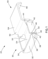
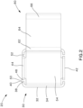
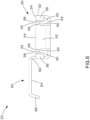
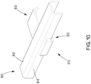
- FIGS. 1-7 illustrate the bracket 20 of the present invention.
- the bracket 20 includes a rung insertion area 30 defined by two sidewalls 32, two gussets 42, and a bottom 54.
- Each sidewall 32 includes a top 34 and two curved arms 36.
- Each curved arm 36 includes an angled ramp 38 that leads to a pointed barb 40 that extends in a direction away from the sidewall 32.
- the gussets 42 include a top 44 and two sides 46.
- the tops 44 of the gussets 42 and the tops 34 of the sidewalls 32 are in the same plane.
- the gusset 42 also include angled ramps 48 that lead to a pointed barb 50 extending from each side 46.
- the pointed barbs 40 extending from each sidewall 32 align with one of the pointed barbs 50 extending from the gusset 42 to form narrow slots 52.
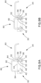
- the slots 52 are narrower than the thickness of the sidewalls 84 of the U-shaped rung 80 (see FIG. 9B ) thereby providing an interference fit with the U-shaped ladder rung 80.
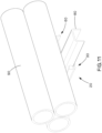
- the U-shaped ladder rung 80 includes a top member 82 and two sidewalls 84 extending from the top member 82 to form a U-shape.
- the U-shaped ladder rung 80 does not include slots or holes in the top member 82 or in the sidewalls 84.
- the bracket 20 is installed by holding the barbs 40, 50 against the sidewalls 84 of the U-shaped ladder rung 80.
- the bracket 20 is impacted with a hammer (not illustrated), or similar tool.
- the angled ramps 38, 48 above the barbs 40, 50 help locate the bracket and reduce the installation force required.
- the slots 52 formed by the barbs 40, 50 of the bracket 20 are narrower than the thickness of the sidewalls 84 of the U-shaped ladder rung 80 thereby providing an interference fit with the sidewalls 84 of the ladder rung 80.
- the upper member 60 of the bracket 20 is flush with the top 82 of the U-shaped ladder rung 80.
- the height and the length of the bracket 20 can be selected based on different manufacturing dimensions of U-shaped ladder rungs.
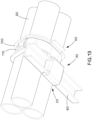
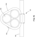
- cables 90 can be positioned on the bracket 20 and ladder rung 80.
- the bracket 20 can also be installed without moving the cables 90 already positioned on a ladder rack.
- the cables 90 are secured to the bracket 20 by a cushion sleeve 100 and a stainless-steel tie 110 or strapping.
- the bracket 20 of the present invention is used for cable management and short circuit applications. As discussed above, the bracket 20 attaches a cable bundle 90 to a U-shaped ladder rack 80. If all three phases of AC current short out at the same time, the cables 90 repel and attract each other with forces that can be significant. The stainless-steel tie 110 or strapping holds the cable 90 together, while the bracket 20 holds the cable 90 to the ladder rung 80.
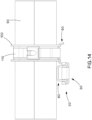
- the sections of cable 90 between the stainless-steel ties 110 or strapping expand during a short circuit due to the forces exerted on the cables 90.
- the cables 90 expand, they often contact the ladder rungs 80 and exert a force on the brackets 20 holding the cable bundle 90 in place.
- the force is mainly in the direction toward the cable bundle 90.
- a force equal and opposite in direction must be applied.
- this equal and opposite force would be achieved with the use of a mechanical fastener.
- the bracket 20 of the present invention does not require a mechanical fastener to hold it in place to create the equal and opposite force necessary for proper performance.
- the bracket 20 of the present invention creates the equal and opposite force via the reinforced barbs 40, 50.
- the barbs 40, 50 located on the sidewalls 32 and the gusset 42 of the bracket 20 hold the bracket 20 in place when an upward force is applied to the upper member 60 of the bracket 20.
- the barbs 40, 50 of the sidewalls 32 and the gusset 42 exert a force on the inner surface of the U-shaped ladder rung 80 holding the bracket 20 in place.
- the barbs 40, 50 hold the bracket 20 in place, hands free, while the stainless-steel tie 110 or strap is being installed.
Landscapes
- Engineering & Computer Science (AREA)
- General Engineering & Computer Science (AREA)
- Mechanical Engineering (AREA)
- Architecture (AREA)
- Civil Engineering (AREA)
- Structural Engineering (AREA)
- Details Of Indoor Wiring (AREA)
- Installation Of Indoor Wiring (AREA)
- Clamps And Clips (AREA)
Claims (9)
- Halterung (20) zur Befestigung an einer U-förmigen Leitersprosse (80), wobei die Halterung Folgendes umfasst:einen Sprosseneinführbereich (30), der durch einen Boden (54), durch zwei Seitenwände (32), die sich von dem Boden erstrecken, und durch zwei Stützbleche (42) definiert wird, die sich von dem Boden erstrecken und zwischen den Seitenwänden (32) positioniert sind, wobei jede Seitenwand eine Oberseite (34) und zwei gekrümmte Arme (36) aufweist und jedes Stützblech eine Oberseite (44) und zwei Seiten (46) aufweist, wobei zwischen jedem gekrümmten Arm (36) der Seitenwände (32) und jeder Seite (46) des Stützblechs Schlitze (52) ausgebildet sind, und ein oberes Glied (60), das sich von der Oberseite einer der Seitenwände (32) erstreckt,wobei die Halterung (20) zur Aufnahme der Seitenwände (84) der U-förmigen Leitersprosse (80) in den Schlitzen (52) ausgestaltet ist, wodurch die U-förmige Leitersprosse an der Halterung (20) befestigt wird, und wobei die Schlitze (52) schmaler als die Dicke der Seitenwände (84) der U-förmigen Leitersprosse (80) sind, wodurch eine Presspassung mit der U-förmigen Leitersprosse (80) bereitgestellt wird.
- Halterung nach Anspruch 1, wobei jeder gekrümmte Arm (36) jeder Seitenwand eine abgewinkelte Rampe (38) aufweist, die zu einem spitzen Widerhaken (40) führt, wobei sich jeder spitze Widerhaken in eine von der Seitenwand weg gehende Richtung erstreckt.
- Halterung nach Anspruch 1, wobei die Stützbleche abgewinkelte Rampen (48) aufweisen, die zu einem spitzen Widerhaken (50) führen, der sich von jeder Seite erstreckt, oder wobei die Oberseiten der Stützbleche und die Oberseiten der Seitenwände (34) in derselben Ebene liegen.
- Halterung nach Anspruch 1, wobei die Schlitze (52) von spitzen Widerhaken (40) definiert werden, die sich von jeder ersten Seitenwand erstrecken, und spitzen Widerhaken (50), die sich von jedem Stützblech (42) erstrecken.
- Halterung nach Anspruch 1, wobei das obere Glied (60) ein erstes gekrümmtes Ende (62), ein horizontales Glied (64) und einen sich nach unten erstreckenden Flansch (66) aufweist.
- Halterung nach einem der vorhergehenden Ansprüche, wobei Ränder des oberen Glieds (60) abgerundet sind, um eine Beschädigung von Kabeln, die an dem horizontalen Glied (64) befestigt sind, zu vermeiden.
- Halterung nach einem vorhergehenden Anspruch 1, wobei das horizontale Glied (64) eine Bügellokalisierung zur Aufnahme eines Bügels zur Befestigung von an dem horizontalen Glied positionierten Kabeln bereitstellt.
- Halterung nach Anspruch 1, wobei jeder gekrümmte Arm (36) jeder Seitenwand eine abgewinkelte Rampe (38) aufweist, die zu einem spitzen Widerhaken (40) führt, und wobei jedes Stützblech (42) eine abgewinkelte Rampe (48) aufweist, die zu einem spitzen Widerhaken (50) führt.
- Kabelverwaltungsanordnung zur Befestigung von Kabeln an einer U-förmigen Leitersprosse (80) eines Leitergerüsts, wobei die Kabelverwaltungsanordnung Folgendes umfasst:die Halterung (20) nach einem der vorhergehenden Ansprüche, wobei das obere Glied (60) der Halterung zur Aufnahme von Kabeln ausgestaltet ist, undeinen Metallbügel, der so angeordnet ist, dass er sich um das obere Glied (60) und darauf positionierte Kabel schlingt, wobei die Halterung zur Aufnahme der Seitenwände (84) der Leitersprosse (80) in den Schlitzen (52) der Halterung angeordnet ist und der Metallbügel zur Befestigung der Kabel an der Halterung und der Leitersprosse angeordnet ist.
Applications Claiming Priority (2)
| Application Number | Priority Date | Filing Date | Title |
|---|---|---|---|
| US201962814380P | 2019-03-06 | 2019-03-06 | |
| US16/804,894 US10811857B2 (en) | 2019-03-06 | 2020-02-28 | Bracket for cable management |
Publications (2)
| Publication Number | Publication Date |
|---|---|
| EP3706272A1 EP3706272A1 (de) | 2020-09-09 |
| EP3706272B1 true EP3706272B1 (de) | 2024-10-09 |
Family
ID=69770740
Family Applications (1)
| Application Number | Title | Priority Date | Filing Date |
|---|---|---|---|
| EP20161128.2A Active EP3706272B1 (de) | 2019-03-06 | 2020-03-05 | Halterung für kabelmanagement |
Country Status (4)
| Country | Link |
|---|---|
| US (1) | US10811857B2 (de) |
| EP (1) | EP3706272B1 (de) |
| KR (1) | KR102570183B1 (de) |
| CN (1) | CN211880008U (de) |
Families Citing this family (6)
| Publication number | Priority date | Publication date | Assignee | Title |
|---|---|---|---|---|
| DE102018003688B4 (de) * | 2018-05-07 | 2021-07-08 | A. Raymond Et Cie | Vorrichtung zur Aufnahme eines Kabelstrangs und System mit einer solchen Vorrichtung |
| US12233325B2 (en) * | 2020-03-10 | 2025-02-25 | Jacob Stewart | Court edge enhancement |
| US11713835B2 (en) * | 2020-06-18 | 2023-08-01 | Panduit Corp. | Cable bracket assembly |
| US11677227B2 (en) | 2021-09-10 | 2023-06-13 | Panduit Corp. | Dual tongue strap cleat bracket |
| USD1116695S1 (en) * | 2024-07-19 | 2026-03-10 | Senhua Zhang | Weed eater rack |
| USD1116730S1 (en) * | 2024-10-04 | 2026-03-10 | Polyplas International Pty Ltd. | Mounting bracket |
Citations (5)
| Publication number | Priority date | Publication date | Assignee | Title |
|---|---|---|---|---|
| US6471171B1 (en) * | 2001-12-28 | 2002-10-29 | Panduit Corp. | 2-piece ladder rack bracket |
| US20140239131A1 (en) * | 2013-02-27 | 2014-08-28 | Panduit Corp. | Ladder Rung Bracket Assembly |
| US20150275578A1 (en) * | 2014-03-25 | 2015-10-01 | Panduit Corp. | Cradle Clamp Bracket Assembly |
| US20160025244A1 (en) * | 2014-07-24 | 2016-01-28 | Cooper Technologies Company | Cable management fitting |
| US20160340978A1 (en) * | 2014-05-30 | 2016-11-24 | Panduit Corp. | Thermal Expansion and Contraction System |
Family Cites Families (24)
| Publication number | Priority date | Publication date | Assignee | Title |
|---|---|---|---|---|
| US2470992A (en) | 1948-01-13 | 1949-05-24 | Harry L Kindorf | Beam clamp for conduit supports |
| US2551146A (en) | 1949-08-25 | 1951-05-01 | Marincic Frank | Cable hanger |
| US3053494A (en) | 1960-04-15 | 1962-09-11 | Daniel Woodhead Company | Hanger |
| US3667711A (en) | 1970-10-13 | 1972-06-06 | Martin S Kissel | Hanger for pipes and conduits |
| US4136423A (en) | 1977-11-07 | 1979-01-30 | Eby Company | Cable clamp and bracket |
| ZW22180A1 (en) * | 1979-10-04 | 1981-06-24 | Cold Air Installations Proprie | Cable clamps |
| US4542871A (en) | 1983-02-14 | 1985-09-24 | Thomas & Betts Corporation | Clamp for mounting cable on channel support |
| US4646395A (en) | 1984-08-06 | 1987-03-03 | Reliance Electric Company | Cable clamp, body portion therefore and method of manufacturing same |
| US4789286A (en) | 1986-02-04 | 1988-12-06 | William Laput | Fitting for channel-shaped framing members |
| DE8622078U1 (de) * | 1986-08-16 | 1986-11-13 | Rittal-Werk Rudolf Loh Gmbh & Co Kg, 6348 Herborn | Lösbare Klemmschelle für Schläuche od.dgl. |
| US4770378A (en) | 1987-11-06 | 1988-09-13 | Yoshio Onishi | Device for fixing conduits to saddles |
| US5678833A (en) | 1995-06-07 | 1997-10-21 | Rollerblade, Inc. | Adjustable fit in-line skate |
| CA2251130A1 (en) | 1997-02-25 | 1998-08-27 | Thomas & Betts International, Inc. | Modular cable tray assembly |
| FR2795449B1 (fr) | 1999-06-28 | 2001-09-28 | Mavil | Barreau ou montant pour echelle a cables, echelle a cables et son procede de montage |
| ITTO20020185U1 (it) | 2002-10-16 | 2004-04-17 | A E C S R L | Terminale per un cablaggio di massa di un veicolo di tipo modulare. |
| US7490802B1 (en) | 2007-10-31 | 2009-02-17 | Teng Tino S | Beam clamp |
| US7677514B1 (en) | 2008-05-16 | 2010-03-16 | Safety Pumping Systems, Llc | No drill equipment support bracket |
| US8770885B2 (en) | 2009-05-27 | 2014-07-08 | Melvin L. Myers | Wedge clamp |
| US8757560B2 (en) * | 2010-06-24 | 2014-06-24 | Wanaka Holdings, LLC | Cable retention device |
| US8931747B2 (en) | 2010-07-16 | 2015-01-13 | Joe N. Davis | Bracket assembly |
| US8714502B1 (en) | 2010-07-16 | 2014-05-06 | Joe N. Davis | Bracket assembly |
| WO2013020567A1 (de) | 2011-08-08 | 2013-02-14 | Ueberall Guenter | Verbindungssystem für sprossen-profile mit holm-profilen |
| US10407985B2 (en) | 2014-03-25 | 2019-09-10 | Panduit Corp. | Cradle clamp bracket assembly |
| US10100861B2 (en) | 2014-11-14 | 2018-10-16 | Cooper Technologies Company | Beam clamp for strut channel |
-
2020
- 2020-02-28 US US16/804,894 patent/US10811857B2/en active Active
- 2020-03-05 KR KR1020200027821A patent/KR102570183B1/ko active Active
- 2020-03-05 EP EP20161128.2A patent/EP3706272B1/de active Active
- 2020-03-06 CN CN202020265202.XU patent/CN211880008U/zh active Active
Patent Citations (5)
| Publication number | Priority date | Publication date | Assignee | Title |
|---|---|---|---|---|
| US6471171B1 (en) * | 2001-12-28 | 2002-10-29 | Panduit Corp. | 2-piece ladder rack bracket |
| US20140239131A1 (en) * | 2013-02-27 | 2014-08-28 | Panduit Corp. | Ladder Rung Bracket Assembly |
| US20150275578A1 (en) * | 2014-03-25 | 2015-10-01 | Panduit Corp. | Cradle Clamp Bracket Assembly |
| US20160340978A1 (en) * | 2014-05-30 | 2016-11-24 | Panduit Corp. | Thermal Expansion and Contraction System |
| US20160025244A1 (en) * | 2014-07-24 | 2016-01-28 | Cooper Technologies Company | Cable management fitting |
Also Published As
| Publication number | Publication date |
|---|---|
| US20200287365A1 (en) | 2020-09-10 |
| EP3706272A1 (de) | 2020-09-09 |
| KR102570183B1 (ko) | 2023-08-24 |
| CN211880008U (zh) | 2020-11-06 |
| US10811857B2 (en) | 2020-10-20 |
| KR20200107844A (ko) | 2020-09-16 |
Similar Documents
| Publication | Publication Date | Title |
|---|---|---|
| EP3706272B1 (de) | Halterung für kabelmanagement | |
| US10246941B2 (en) | Ladder rung bracket assembly | |
| US8991774B2 (en) | Cable tie mount | |
| US12062894B2 (en) | Cable clips for wire management | |
| EP3837745B1 (de) | Kabelverwaltungsanordnung | |
| US8702047B2 (en) | Electrical box mounting bracket | |
| US7654492B2 (en) | Wire bundle support system | |
| CN105794062B (zh) | 电缆连接器及配电箱组合件 | |
| US6674000B2 (en) | Simplified interconnect for center of wide body aircraft | |
| CA2948770C (en) | Pipe clamp | |
| JP4875177B2 (ja) | バンドクランプ | |
| AU2020201632B2 (en) | Bracket for cable management | |
| WO2015083521A1 (ja) | 車両用部品の仮留め構造 |
Legal Events
| Date | Code | Title | Description |
|---|---|---|---|
| PUAI | Public reference made under article 153(3) epc to a published international application that has entered the european phase |
Free format text: ORIGINAL CODE: 0009012 |
|
| STAA | Information on the status of an ep patent application or granted ep patent |
Free format text: STATUS: THE APPLICATION HAS BEEN PUBLISHED |
|
| AK | Designated contracting states |
Kind code of ref document: A1 Designated state(s): AL AT BE BG CH CY CZ DE DK EE ES FI FR GB GR HR HU IE IS IT LI LT LU LV MC MK MT NL NO PL PT RO RS SE SI SK SM TR |
|
| AX | Request for extension of the european patent |
Extension state: BA ME |
|
| STAA | Information on the status of an ep patent application or granted ep patent |
Free format text: STATUS: REQUEST FOR EXAMINATION WAS MADE |
|
| 17P | Request for examination filed |
Effective date: 20210126 |
|
| RBV | Designated contracting states (corrected) |
Designated state(s): AL AT BE BG CH CY CZ DE DK EE ES FI FR GB GR HR HU IE IS IT LI LT LU LV MC MK MT NL NO PL PT RO RS SE SI SK SM TR |
|
| STAA | Information on the status of an ep patent application or granted ep patent |
Free format text: STATUS: EXAMINATION IS IN PROGRESS |
|
| 17Q | First examination report despatched |
Effective date: 20211109 |
|
| GRAP | Despatch of communication of intention to grant a patent |
Free format text: ORIGINAL CODE: EPIDOSNIGR1 |
|
| STAA | Information on the status of an ep patent application or granted ep patent |
Free format text: STATUS: GRANT OF PATENT IS INTENDED |
|
| INTG | Intention to grant announced |
Effective date: 20240603 |
|
| GRAS | Grant fee paid |
Free format text: ORIGINAL CODE: EPIDOSNIGR3 |
|
| GRAA | (expected) grant |
Free format text: ORIGINAL CODE: 0009210 |
|
| STAA | Information on the status of an ep patent application or granted ep patent |
Free format text: STATUS: THE PATENT HAS BEEN GRANTED |
|
| AK | Designated contracting states |
Kind code of ref document: B1 Designated state(s): AL AT BE BG CH CY CZ DE DK EE ES FI FR GB GR HR HU IE IS IT LI LT LU LV MC MK MT NL NO PL PT RO RS SE SI SK SM TR |
|
| REG | Reference to a national code |
Ref country code: CH Ref legal event code: EP |
|
| REG | Reference to a national code |
Ref country code: DE Ref legal event code: R096 Ref document number: 602020038895 Country of ref document: DE |
|
| REG | Reference to a national code |
Ref country code: IE Ref legal event code: FG4D |
|
| REG | Reference to a national code |
Ref country code: LT Ref legal event code: MG9D |
|
| REG | Reference to a national code |
Ref country code: NL Ref legal event code: MP Effective date: 20241009 |
|
| REG | Reference to a national code |
Ref country code: AT Ref legal event code: MK05 Ref document number: 1731651 Country of ref document: AT Kind code of ref document: T Effective date: 20241009 |
|
| PG25 | Lapsed in a contracting state [announced via postgrant information from national office to epo] |
Ref country code: NL Free format text: LAPSE BECAUSE OF FAILURE TO SUBMIT A TRANSLATION OF THE DESCRIPTION OR TO PAY THE FEE WITHIN THE PRESCRIBED TIME-LIMIT Effective date: 20241009 |
|
| PG25 | Lapsed in a contracting state [announced via postgrant information from national office to epo] |
Ref country code: NL Free format text: LAPSE BECAUSE OF FAILURE TO SUBMIT A TRANSLATION OF THE DESCRIPTION OR TO PAY THE FEE WITHIN THE PRESCRIBED TIME-LIMIT Effective date: 20241009 |
|
| PG25 | Lapsed in a contracting state [announced via postgrant information from national office to epo] |
Ref country code: IS Free format text: LAPSE BECAUSE OF FAILURE TO SUBMIT A TRANSLATION OF THE DESCRIPTION OR TO PAY THE FEE WITHIN THE PRESCRIBED TIME-LIMIT Effective date: 20250209 Ref country code: HR Free format text: LAPSE BECAUSE OF FAILURE TO SUBMIT A TRANSLATION OF THE DESCRIPTION OR TO PAY THE FEE WITHIN THE PRESCRIBED TIME-LIMIT Effective date: 20241009 Ref country code: PT Free format text: LAPSE BECAUSE OF FAILURE TO SUBMIT A TRANSLATION OF THE DESCRIPTION OR TO PAY THE FEE WITHIN THE PRESCRIBED TIME-LIMIT Effective date: 20250210 |
|
| PGFP | Annual fee paid to national office [announced via postgrant information from national office to epo] |
Ref country code: DE Payment date: 20250327 Year of fee payment: 6 |
|
| PG25 | Lapsed in a contracting state [announced via postgrant information from national office to epo] |
Ref country code: FI Free format text: LAPSE BECAUSE OF FAILURE TO SUBMIT A TRANSLATION OF THE DESCRIPTION OR TO PAY THE FEE WITHIN THE PRESCRIBED TIME-LIMIT Effective date: 20241009 |
|
| PG25 | Lapsed in a contracting state [announced via postgrant information from national office to epo] |
Ref country code: BG Free format text: LAPSE BECAUSE OF FAILURE TO SUBMIT A TRANSLATION OF THE DESCRIPTION OR TO PAY THE FEE WITHIN THE PRESCRIBED TIME-LIMIT Effective date: 20241009 |
|
| PG25 | Lapsed in a contracting state [announced via postgrant information from national office to epo] |
Ref country code: ES Free format text: LAPSE BECAUSE OF FAILURE TO SUBMIT A TRANSLATION OF THE DESCRIPTION OR TO PAY THE FEE WITHIN THE PRESCRIBED TIME-LIMIT Effective date: 20241009 |
|
| PG25 | Lapsed in a contracting state [announced via postgrant information from national office to epo] |
Ref country code: NO Free format text: LAPSE BECAUSE OF FAILURE TO SUBMIT A TRANSLATION OF THE DESCRIPTION OR TO PAY THE FEE WITHIN THE PRESCRIBED TIME-LIMIT Effective date: 20250109 |
|
| PG25 | Lapsed in a contracting state [announced via postgrant information from national office to epo] |
Ref country code: GR Free format text: LAPSE BECAUSE OF FAILURE TO SUBMIT A TRANSLATION OF THE DESCRIPTION OR TO PAY THE FEE WITHIN THE PRESCRIBED TIME-LIMIT Effective date: 20250110 Ref country code: LV Free format text: LAPSE BECAUSE OF FAILURE TO SUBMIT A TRANSLATION OF THE DESCRIPTION OR TO PAY THE FEE WITHIN THE PRESCRIBED TIME-LIMIT Effective date: 20241009 Ref country code: AT Free format text: LAPSE BECAUSE OF FAILURE TO SUBMIT A TRANSLATION OF THE DESCRIPTION OR TO PAY THE FEE WITHIN THE PRESCRIBED TIME-LIMIT Effective date: 20241009 |
|
| PG25 | Lapsed in a contracting state [announced via postgrant information from national office to epo] |
Ref country code: PL Free format text: LAPSE BECAUSE OF FAILURE TO SUBMIT A TRANSLATION OF THE DESCRIPTION OR TO PAY THE FEE WITHIN THE PRESCRIBED TIME-LIMIT Effective date: 20241009 |
|
| PGFP | Annual fee paid to national office [announced via postgrant information from national office to epo] |
Ref country code: FR Payment date: 20250325 Year of fee payment: 6 |
|
| PGFP | Annual fee paid to national office [announced via postgrant information from national office to epo] |
Ref country code: GB Payment date: 20250327 Year of fee payment: 6 |
|
| PG25 | Lapsed in a contracting state [announced via postgrant information from national office to epo] |
Ref country code: RS Free format text: LAPSE BECAUSE OF FAILURE TO SUBMIT A TRANSLATION OF THE DESCRIPTION OR TO PAY THE FEE WITHIN THE PRESCRIBED TIME-LIMIT Effective date: 20250109 |
|
| PG25 | Lapsed in a contracting state [announced via postgrant information from national office to epo] |
Ref country code: SM Free format text: LAPSE BECAUSE OF FAILURE TO SUBMIT A TRANSLATION OF THE DESCRIPTION OR TO PAY THE FEE WITHIN THE PRESCRIBED TIME-LIMIT Effective date: 20241009 |
|
| PG25 | Lapsed in a contracting state [announced via postgrant information from national office to epo] |
Ref country code: DK Free format text: LAPSE BECAUSE OF FAILURE TO SUBMIT A TRANSLATION OF THE DESCRIPTION OR TO PAY THE FEE WITHIN THE PRESCRIBED TIME-LIMIT Effective date: 20241009 |
|
| REG | Reference to a national code |
Ref country code: DE Ref legal event code: R097 Ref document number: 602020038895 Country of ref document: DE |
|
| PG25 | Lapsed in a contracting state [announced via postgrant information from national office to epo] |
Ref country code: EE Free format text: LAPSE BECAUSE OF FAILURE TO SUBMIT A TRANSLATION OF THE DESCRIPTION OR TO PAY THE FEE WITHIN THE PRESCRIBED TIME-LIMIT Effective date: 20241009 |
|
| PG25 | Lapsed in a contracting state [announced via postgrant information from national office to epo] |
Ref country code: RO Free format text: LAPSE BECAUSE OF FAILURE TO SUBMIT A TRANSLATION OF THE DESCRIPTION OR TO PAY THE FEE WITHIN THE PRESCRIBED TIME-LIMIT Effective date: 20241009 |
|
| PG25 | Lapsed in a contracting state [announced via postgrant information from national office to epo] |
Ref country code: SK Free format text: LAPSE BECAUSE OF FAILURE TO SUBMIT A TRANSLATION OF THE DESCRIPTION OR TO PAY THE FEE WITHIN THE PRESCRIBED TIME-LIMIT Effective date: 20241009 |
|
| PG25 | Lapsed in a contracting state [announced via postgrant information from national office to epo] |
Ref country code: CZ Free format text: LAPSE BECAUSE OF FAILURE TO SUBMIT A TRANSLATION OF THE DESCRIPTION OR TO PAY THE FEE WITHIN THE PRESCRIBED TIME-LIMIT Effective date: 20241009 |
|
| PG25 | Lapsed in a contracting state [announced via postgrant information from national office to epo] |
Ref country code: IT Free format text: LAPSE BECAUSE OF FAILURE TO SUBMIT A TRANSLATION OF THE DESCRIPTION OR TO PAY THE FEE WITHIN THE PRESCRIBED TIME-LIMIT Effective date: 20241009 |
|
| PLBE | No opposition filed within time limit |
Free format text: ORIGINAL CODE: 0009261 |
|
| STAA | Information on the status of an ep patent application or granted ep patent |
Free format text: STATUS: NO OPPOSITION FILED WITHIN TIME LIMIT |
|
| PG25 | Lapsed in a contracting state [announced via postgrant information from national office to epo] |
Ref country code: SE Free format text: LAPSE BECAUSE OF FAILURE TO SUBMIT A TRANSLATION OF THE DESCRIPTION OR TO PAY THE FEE WITHIN THE PRESCRIBED TIME-LIMIT Effective date: 20241009 |
|
| 26N | No opposition filed |
Effective date: 20250710 |
|
| PG25 | Lapsed in a contracting state [announced via postgrant information from national office to epo] |
Ref country code: MC Free format text: LAPSE BECAUSE OF FAILURE TO SUBMIT A TRANSLATION OF THE DESCRIPTION OR TO PAY THE FEE WITHIN THE PRESCRIBED TIME-LIMIT Effective date: 20241009 |
|
| REG | Reference to a national code |
Ref country code: CH Ref legal event code: H13 Free format text: ST27 STATUS EVENT CODE: U-0-0-H10-H13 (AS PROVIDED BY THE NATIONAL OFFICE) Effective date: 20251023 |
|
| PG25 | Lapsed in a contracting state [announced via postgrant information from national office to epo] |
Ref country code: LU Free format text: LAPSE BECAUSE OF NON-PAYMENT OF DUE FEES Effective date: 20250305 |
|
| REG | Reference to a national code |
Ref country code: BE Ref legal event code: MM Effective date: 20250331 |
|
| PG25 | Lapsed in a contracting state [announced via postgrant information from national office to epo] |
Ref country code: BE Free format text: LAPSE BECAUSE OF NON-PAYMENT OF DUE FEES Effective date: 20250331 |
|
| PG25 | Lapsed in a contracting state [announced via postgrant information from national office to epo] |
Ref country code: CH Free format text: LAPSE BECAUSE OF NON-PAYMENT OF DUE FEES Effective date: 20250331 |
|
| PG25 | Lapsed in a contracting state [announced via postgrant information from national office to epo] |
Ref country code: IE Free format text: LAPSE BECAUSE OF NON-PAYMENT OF DUE FEES Effective date: 20250305 |