EP3706240A1 - Antenna - Google Patents
Antenna Download PDFInfo
- Publication number
- EP3706240A1 EP3706240A1 EP20150934.6A EP20150934A EP3706240A1 EP 3706240 A1 EP3706240 A1 EP 3706240A1 EP 20150934 A EP20150934 A EP 20150934A EP 3706240 A1 EP3706240 A1 EP 3706240A1
- Authority
- EP
- European Patent Office
- Prior art keywords
- antenna
- facing portion
- terminal
- facing
- feeding terminal
- Prior art date
- Legal status (The legal status is an assumption and is not a legal conclusion. Google has not performed a legal analysis and makes no representation as to the accuracy of the status listed.)
- Granted
Links
Images




Classifications
-
- H—ELECTRICITY
- H01—ELECTRIC ELEMENTS
- H01Q—ANTENNAS, i.e. RADIO AERIALS
- H01Q1/00—Details of, or arrangements associated with, antennas
- H01Q1/12—Supports; Mounting means
- H01Q1/22—Supports; Mounting means by structural association with other equipment or articles
- H01Q1/24—Supports; Mounting means by structural association with other equipment or articles with receiving set
- H01Q1/241—Supports; Mounting means by structural association with other equipment or articles with receiving set used in mobile communications, e.g. GSM
- H01Q1/242—Supports; Mounting means by structural association with other equipment or articles with receiving set used in mobile communications, e.g. GSM specially adapted for hand-held use
- H01Q1/243—Supports; Mounting means by structural association with other equipment or articles with receiving set used in mobile communications, e.g. GSM specially adapted for hand-held use with built-in antennas
-
- H—ELECTRICITY
- H01—ELECTRIC ELEMENTS
- H01Q—ANTENNAS, i.e. RADIO AERIALS
- H01Q9/00—Electrically-short antennas having dimensions not more than twice the operating wavelength and consisting of conductive active radiating elements
- H01Q9/04—Resonant antennas
-
- H—ELECTRICITY
- H01—ELECTRIC ELEMENTS
- H01Q—ANTENNAS, i.e. RADIO AERIALS
- H01Q9/00—Electrically-short antennas having dimensions not more than twice the operating wavelength and consisting of conductive active radiating elements
- H01Q9/04—Resonant antennas
- H01Q9/0407—Substantially flat resonant element parallel to ground plane, e.g. patch antenna
- H01Q9/0414—Substantially flat resonant element parallel to ground plane, e.g. patch antenna in a stacked or folded configuration
-
- H—ELECTRICITY
- H01—ELECTRIC ELEMENTS
- H01P—WAVEGUIDES; RESONATORS, LINES, OR OTHER DEVICES OF THE WAVEGUIDE TYPE
- H01P7/00—Resonators of the waveguide type
-
- H—ELECTRICITY
- H01—ELECTRIC ELEMENTS
- H01Q—ANTENNAS, i.e. RADIO AERIALS
- H01Q1/00—Details of, or arrangements associated with, antennas
- H01Q1/12—Supports; Mounting means
- H01Q1/22—Supports; Mounting means by structural association with other equipment or articles
-
- H—ELECTRICITY
- H01—ELECTRIC ELEMENTS
- H01Q—ANTENNAS, i.e. RADIO AERIALS
- H01Q1/00—Details of, or arrangements associated with, antennas
- H01Q1/36—Structural form of radiating elements, e.g. cone, spiral, umbrella; Particular materials used therewith
-
- H—ELECTRICITY
- H01—ELECTRIC ELEMENTS
- H01Q—ANTENNAS, i.e. RADIO AERIALS
- H01Q1/00—Details of, or arrangements associated with, antennas
- H01Q1/50—Structural association of antennas with earthing switches, lead-in devices or lightning protectors
-
- H—ELECTRICITY
- H01—ELECTRIC ELEMENTS
- H01Q—ANTENNAS, i.e. RADIO AERIALS
- H01Q7/00—Loop antennas with a substantially uniform current distribution around the loop and having a directional radiation pattern in a plane perpendicular to the plane of the loop
-
- H—ELECTRICITY
- H01—ELECTRIC ELEMENTS
- H01Q—ANTENNAS, i.e. RADIO AERIALS
- H01Q9/00—Electrically-short antennas having dimensions not more than twice the operating wavelength and consisting of conductive active radiating elements
- H01Q9/04—Resonant antennas
- H01Q9/0407—Substantially flat resonant element parallel to ground plane, e.g. patch antenna
- H01Q9/045—Substantially flat resonant element parallel to ground plane, e.g. patch antenna with particular feeding means
Definitions
- This invention relates to an antenna to be mounted on an object and, in particular, to an antenna having a split-ring resonator structure.
- Patent Document 1 discloses an antenna having a split-ring resonator structure.
- the antenna 90 of Patent Document 1 has a dielectric layer 910, a conductive layer 920 formed on one of a pair of main surfaces of the dielectric layer 910, a feed line 930 formed on the other of the main surfaces of the dielectric layer 910.
- the conductive layer 920 is formed in a C-shape.
- both end portions of the conductive layer 920 are arranged apart from each other and face each other to form a capacitor 940.
- the conductive layer 920 and the feed line 930 are connected to each other with a via 950 piercing the dielectric layer 910.
- the via 950 connects an end portion of the feed line 930 to a vicinity of one of the end portions of the conductive layer 920.
- the antenna of Patent Document 1 is fabricated by the use of a printed circuit board. If the antenna fabricated by the use of the printed circuit board does not have desired characteristics owing to fabrication variations, it is necessary to retrofit a matching circuit, such as an inductor, a capacitor or the like, to the antenna, or to remake the printed circuit board. Accordingly, the antenna of Patent Document 1 has a problem that a cost thereof tends to become grater.
- the problem of the antenna of Patent Document 1 may be reduced by producing an antenna as a discrete part. In that case, however, there is a possibility that, during a reflow process executed to mount the antenna on an object such as a substrate, antenna characteristics are changed owing to a difference in coefficient of linear expansion between the antenna and the object.
- the present invention provides an antenna to be mounted on an object, which is as follows.
- the antenna comprises a main portion, a facing portion, a first feeding terminal, a second feeding terminal and an additional terminal.
- the main portion has a ring-shape with a split and has a first end portion and a second end portion which form the split.
- the facing portion has a first facing portion provided on the first end portion and a second facing portion provided on the second end portion.
- the first facing portion and the second facing portion arranged apart from each other and face each other.
- the first feeding terminal, the second feed terminal and the additional terminal are provided on the main portion and are parts which are fixed to the object when the antenna is mounted on the object.
- the first feeding terminal is situated nearer to the first end portion on the main portion than the second feeding terminal is situated.
- the additional terminal is situated nearer to the second end portion on the main portion than the second feeding terminal is situated.
- the first feeding terminal is situated nearer to the first end portion than the second feeding terminal is situated, and the additional terminal is situated nearer to the second end portion than the second feeding terminal is situated.
- the first feeding terminal is situated near to the first facing portion provided on the first end portion, and the additional terminal is situated near to the second facing portion provided on the second end portion.
- an antenna 10 has a split-ring resonator structure.
- the antenna 10 is provided with a main portion 20, a facing portion 30, a first feeding terminal 40, three second feeding terminals 50 (501, 503, 505), an additional terminal 60 and three fixed portions 70 (701, 703, 705).
- the antenna 10 is a single-piece member which is formed by punching a single metal sheet and bending the punched metal sheet.
- the main portion 20 has a ring-shape with a split 22.
- the "ring-shape” is not limited to a circular-shape but includes other shapes such as an oval-shape, a polygonal-shape and so on.
- the main portion 20 has an approximately rectangular-shape with four sides.
- the main portion 20 has a first end portion 221 and a second end portion 223 which form the split 22.
- the main portion 20 is provided with a first side portion 201 extending in a lateral direction, a second side portion 203 and a third side portion 205 which extend forward from both ends of the first side portion 201, respectively, and a fourth side portion 207 located between a front end portion of the second side portion 203 and a front end portion of the third side portion 205.
- the lateral direction is an X-direction.
- a front-rear direction is a Y-direction.
- a negative Y-direction is directed forward while a positive Y-direction is directed rearward.
- the split 22 is formed at the middle of the fourth side portion 207 in the lateral direction.
- the fourth side portion 207 is divided in two portions, a fourth side right part 207R and a fourth side left part 207L, by the split 22.
- the first end portion 221 of the main portion 20 is one of end portions of the fourth side right part 207R while the second end portion 223 is one of end portions of the fourth side left part 207L.
- the facing portion 30 is situated between the first side portion 201 of the main portion 20 and the fourth side portion 207 of the main portion 20 in the front-rear direction. Moreover, the facing portion 30 is situated between the second side portion 203 of the main portion 20 and the third side portion 205 of the main portion 20 in the lateral direction. In addition, the facing portion 30 is flush with the main portion 20.
- the facing portion 30 is provided on specific one of the sides of the main portion 20. In more detail, the facing portion 30 is provided on a middle portion of the fourth side portion 207 of the main portion 20. That is, the specific one of the sides is the fourth side portion 207 in the present embodiment.
- the present invention is not limited thereto.
- the facing portion 30 may be provided so that a distance from the facing portion 30 to the second side portion 203 is shorter or longer than a distance from the facing portion 30 to the third side portion 205. In that modification, the split 22 of the main portion 20 would be situated near to one of the second side portion 203 and the third side portion 205.
- the facing portion 30 is situated between the first side portion 201 of the main portion 20 and the fourth side portion 207 of the main portion 20 in the front-rear direction. Moreover, the facing portion 30 is situated between the second side portion 203 of the main portion 20 and the third side portion 205 of the main portion 20 in the lateral direction.
- the facing portion 30 has a first facing portion 301 and a second facing portion 303. Then, the first facing portion 301 and the second facing portion 303 are provided on the first end portion 221 of the main portion 20 and the second end portion 223 of the main portion 20, respectively.
- the first facing portion 301 and the second facing portion 303 extend rearward from the first end portion 221 and the second end portion 223, respectively.
- the first facing portion 301 and the second facing portion 303 are apart from the first side portion 201 of the main portion 20, the second side portion 203 of the main portion 20 and the third side portion 205 of the main portion 20.
- the first facing portion 301 and the second facing portion 303 are arranged apart from each other and face each other.
- each of the first facing portion 301 and the second facing portion 303 has a comb-shape.
- the first facing portion 301 and the second facing portion 303 are arranged with a space left therebetween so that tooth of the first facing portion 301 and tooth of the second facing portion 303 are alternately arranged in the front-rear direction.
- the first facing portion 301 and the second facing portion 303 form an interdigital portion 30, and an interdigital slot 32 is made between the first facing portion 301 and the second facing portion 303.
- the first facing portion 301 and the second facing portion 303 form a capacitor.
- the first end portion 221 of the main portion 20 and the second end portion 223 of the main portion 20 also form a part of the interdigital portion 30.
- the main portion 20 forms an inductor and constitutes an LC resonant circuit in conjunction with the facing portion 30.
- the first feeding terminal 40 is provided on the main portion 20.
- the first feeding terminal 40 of the present embodiment is provided nearer to the first end portion 221 than any of the second feeding terminals 50 is provided.
- the first feeding terminal 40 is situated between any of the second feeding terminals 50 and the first end portion 221 on the main portion 20.
- the first feeding terminal 40 is provided on the main portion 20 so that a current path between the first feeding terminal 40 and the first end portion 221 is shorter than a current path between the first feeding terminal 40 and each of the second feeding terminals 50.
- the first feeding terminal 40 is provided on the fourth side right part 207R of the main portion 20.
- the first feeding terminal 40 is situated near to the first end portion 221 but away from the first end portion 221 and the first facing portion 301.
- a shortest distance between the first feeding terminal 40 and the first facing portion 301 is shorter than a shortest distance between the first feeding terminal 40 and the second feeding terminal 503.
- the first feeding terminal 40 has a first part 401 extending from an inside edge of the fourth side right part 207R of the main portion 20 in an inward direction of the main portion 20 and a second part 403 extending from an end of the first part 401 in an intersecting direction intersecting the inward direction via a bent part 410.
- the intersecting direction is directed downward.
- An up-down direction is a Z-direction in the present embodiment. A positive Z-direction is directed upward while a negative Z-direction is directed downward.
- the additional terminal 60 is situated opposite to the first feeding terminal 40 across the facing portion 30.
- an arrangement of the additional terminal 60 and the first feeding terminal 40 is symmetrical with respect to the facing portion 30.
- the additional terminal 60 is situated between any of the second feeding terminals 50 and the second end portion 223 on the main portion 20.
- the arrangement of the additional terminal 60 and the first feeding terminal 40 is surface-symmetrical with respect to a plane (hereinafter referred to as a reference plane) perpendicular to the lateral direction and passing through the middle, in the lateral direction, of the facing portion 30.
- a reference plane perpendicular to the lateral direction and passing through the middle, in the lateral direction, of the facing portion 30.
- the present invention is not limited thereto.
- the arrangement of the additional terminal 60 and the first feeding terminal 40 may not be symmetrical.
- the additional terminal 60 is provided on the fourth side left part 207L of the main portion 20 in the present embodiment.
- the additional terminal 60 is provided, on the main portion 20, nearer to the second end portion 223 than any one of the second feeding terminals 50 is provided.
- the additional terminal 60 is situated near to the second end portion 223 but away from the second end portion 223 and the second facing portion 303.
- a shortest distance between the additional terminal 60 and the second facing portion 303 is shorter than a shortest distance between the additional terminal 60 and the second feeding terminal 505.
- the additional terminal 60 is formed similarly to the first feeding terminal 40.
- the additional terminal 60 has a first part 601 extending from an inside edge of the fourth side left part 207L of the main portion 20 in the inward direction of the main portion 20 and a second part 603 extending from an end of the first part 601 in the intersecting direction intersecting the inward direction via a bent part 610.
- the second part 603 of the additional terminal 60 extends downward.
- the additional terminal 60 may have a different shape and a different size which are different from those of the first feeding terminal 40.
- the shape and the size of the additional terminal 60 allows a resonance frequency of the antenna 10 to be varied. However, it is easy to design the antenna 10 in a case where the first feeding terminal 40 and the additional terminal 60 have the same shape and the same size and are arranged on symmetric positions when compared with other cases.
- each of the second feeding terminals 501, 503 and 505 is provided on the main portion 20 via a bent part 510.
- the second feeding terminals 501, 503 and 505 are provided on the first side portion 201 of the main portion 20, the second side portion 203 of the main portion 20 and the third side portion 205 of the main portion 20, respectively, via the bent parts 510.
- the second feeding terminal 501 has a rectangular plate-shape long in the lateral direction and extends downward.
- Each of the second feeding terminals 503 and 505 has a rectangular plate-shape long in the front-rear direction and extends downward.
- the second feeding terminals 50 are arranged to be mirror images of each other with respect to the facing portion 30.
- the arrangement of the second feeding terminals 50 is symmetrical with respect to the facing portion 30.
- the present invention is not limited thereto.
- the second feeding terminals 50 may be arranged not to be mirror images of each other with respect to the facing portion 30.
- one of the second feeding terminals 50 is essential, and the remains are optional.
- the fixed portions 701, 703 and 705 correspond to the second feeding terminals 501, 503 and 505, respectively.
- the number of the fixed portions 70 is equal to the number of the second feeding terminals 50.
- each of the second feeding terminals 501, 503 and 505 may be provided with a plurality of the fixed portions 70.
- the fixed portions 701, 703 and 705 are integrally formed with the second feeding terminals 501, 503 and 505, respectively.
- the fixed portions 701, 703 and 705 extend downward from lower edges of the second feeding terminals 501, 503 and 505, respectively.
- the fixed portions 701, 703 and 705 can be considered as parts of the second feeding terminals 501, 503 and 505. In the up-down direction, positions of lower edges of the fixed portions 701, 703 and 705 approximately coincide with a position of a lower edge of the first feeding terminal 40 and a position of a lower edge of the additional terminal 60.
- the fixed portions 70 are arranged to be mirror images of each other with respect to the facing portion 30.
- the arrangement of the fixed portions 70 is symmetrical with respect to the facing portion 30.
- the arrangement of the fixed portions 70 is surface-symmetrical with respect to the reference plane.
- the fixed portion 701 has a shape long in the lateral direction and is provided at the middle of the second feeding terminal 501 in the lateral direction.
- the fixed portion 703 and the fixed portion 705 have shapes long in the front-rear direction and are provided on a front end portion of the second side portion 203 and a front end portion of the third side portion 205, respectively.
- the present invention is not limited thereto.
- the arrangement of the fixed portions 70 may be asymmetrical with respect to the facing portion 30. However, symmetrical arrangement of the fixed portions 70 causes uniform deformation of the antenna 10 upon a reflow process, and thereby change of characteristics of the antenna 10 can be suppressed. In addition, when the antenna 10 receives an external force unexpected, the symmetrical arrangement of the fixed portions 70 can disperse the external force appropriately to prevent or restrain deformation of the antenna 10.
- the antenna 10 (see Figs. 1 and 2 ) according to the present embodiment is mounted on an object (not shown).
- the object is a printed circuit board, for example.
- the object has an antenna mount surface (not shown), and a plurality of connection pads (not shown) are formed on the antenna mount surface.
- the object is provided with a feed line (not shown) to be connected to the first feeding terminal 40 of the antenna 10 and a ground plane (not shown) to be connected to the second feeding terminals 50.
- each of the second part 403 of the first feeding terminal 40, the second part 603 of the additional terminal 60 and the fixed portions 70 is fixed on the connection pad (not shown) corresponding thereto.
- the first feeding terminal 40 is electrically connected to the feed line (not shown) via the connection pad corresponding thereto.
- the second feeding terminals 50 are electrically connected to the ground plane (not shown) via the fixed portions 70 and the connection pads corresponding thereto. With this structure, feeding can be carried out between the first feeding terminal 40 and the second feeding terminals 50.
- the additional terminal 60 is connected to neither the feed line nor the ground plane in the present embodiment.
- the first feeding terminal 40 is provided nearer to the first facing portion 301
- the additional terminal 60 is provided nearer to the second facing portion 303.
- both of the first feeding terminal 40 and the additional terminal 60 are fixed to the object (not shown).
- the fourth side right part 207R and the fourth side left part 207L can be equalized in mechanical strength.
- an influence on the fourth side right part 207R and the first facing portion 301 can be balanced with an influence on the fourth side left part 207L and the second facing portion 303.
- a design of the antenna 10 can be carried out in consideration of change of relative positions of the first facing portion 301 and the second facing portion 303 that is caused by the reflow process so that the antenna 10 having stable characteristics can be obtained.
- an antenna 10A according to the present embodiment is provided with a third facing portion 305 and a fourth facing portion 307 in addition to the same structure as the antenna 10 according to the first embodiment.
- the same reference numerals are used for the same or corresponding components as the first embodiment.
- the third facing portion 305 has a first connection portion 311 and a first comb portion 313. Moreover, the third facing portion 305 has a second connection portion 315 and a second comb portion 317.
- the first connection portion 311 has a C-shape when viewed along the lateral direction.
- the first connection portion 311 extends forward from a first end portion 221 of a main portion 20, then extends upward, and further extends rearward.
- the second connection portion 315 has the same shape as the first connection portion 311.
- the second connection portion 315 extends forward from a second end portion 223 of the main portion 20, then extends upward, and further extends rearward.
- the first comb portion 313 and the second comb portion 317 extend rearward from an end portion of the first connection portion 311 and an end portion of the second connection portion 315, respectively.
- the first comb portion 313 has the same shape and the same size as a first facing portion 301.
- the second comb portion 317 has the same shape and the same size as a second facing portion 303.
- the first comb portion 313 and the second comb portion 317 are flush with each other and arranged in parallel with the first facing portion 301 and the second facing portion 303.
- a facing portion 30 has a two layer structure.
- the third facing portion 305 and the fourth facing portion 307 form the facing portion (interdigital portion) 30 in conjunction with the first facing portion 301 and the second facing portion 303.
- a capacitance of the capacitor can be increased without increase of a size of the interdigital portion 30 in a plane perpendicular to the up-down direction.
- the resonance frequency of the antenna 10A is constant, increase of the capacitance of the capacitor allows an inductance of the main portion 20 to be reduced.
- a size of the main portion 20 of the antenna 10A can be reduced in the plane perpendicular to the up-down direction. In other words, a footprint of the antenna 10A on an object (not shown) can be reduced.
- an additional terminal 60 is provided opposite to a first feeding terminal 40 across the facing portion 30, similarly to the antenna 10 according to the first embodiment.
- the additional terminal 60 is provided to be a mirror image of the first feeding terminal 40 with respect to the facing portion 30. Accordingly, in a reflow process in which the antenna 10A is mounted on the object (not shown), an influence on a fourth side right part 207R, the first facing portion 301 and the third facing portion 305 can be balanced with an influence on the fourth side left part 207L, the second facing portion 303 and the fourth facing portion 307.
- each of a relative positional relationship between the first facing portion 301 and the second facing portion 303 and a relative positional relationship between the third facing portion 305 and the fourth facing portion 307 can be maintained, and thereby the antenna 10A having stable characteristics can be obtained.
- the facing portion 30 has the two layer structure in the second embodiment, the facing portion 30 may have three or more layer structure.
- the third facing portion 305 and the fourth facing portion 307 are arranged above the first facing portion 301 and the second facing portion 303, respectively, in the up-down direction in the second embodiment, the third facing portion 305 and the fourth facing portion 307 may be arranged below the first facing portion 301 and the second facing portion 303, respectively, in the up-down direction.
Landscapes
- Engineering & Computer Science (AREA)
- Computer Networks & Wireless Communication (AREA)
- Details Of Aerials (AREA)
- Support Of Aerials (AREA)
Abstract
Description
- This invention relates to an antenna to be mounted on an object and, in particular, to an antenna having a split-ring resonator structure.
-
JP 2016-225956 A Fig. 15 , theantenna 90 of Patent Document 1 has adielectric layer 910, aconductive layer 920 formed on one of a pair of main surfaces of thedielectric layer 910, afeed line 930 formed on the other of the main surfaces of thedielectric layer 910. Theconductive layer 920 is formed in a C-shape. In addition, both end portions of theconductive layer 920 are arranged apart from each other and face each other to form acapacitor 940. Theconductive layer 920 and thefeed line 930 are connected to each other with avia 950 piercing thedielectric layer 910. In detail, thevia 950 connects an end portion of thefeed line 930 to a vicinity of one of the end portions of theconductive layer 920. - The antenna of Patent Document 1 is fabricated by the use of a printed circuit board. If the antenna fabricated by the use of the printed circuit board does not have desired characteristics owing to fabrication variations, it is necessary to retrofit a matching circuit, such as an inductor, a capacitor or the like, to the antenna, or to remake the printed circuit board. Accordingly, the antenna of Patent Document 1 has a problem that a cost thereof tends to become grater.
- Therefore, it is an object of the present invention to provide an antenna which can be fabricated at a low cost and obtain stable characteristics.
- The problem of the antenna of Patent Document 1 may be reduced by producing an antenna as a discrete part. In that case, however, there is a possibility that, during a reflow process executed to mount the antenna on an object such as a substrate, antenna characteristics are changed owing to a difference in coefficient of linear expansion between the antenna and the object.
- In view of the forgoing, the present invention provides an antenna to be mounted on an object, which is as follows.
- One aspect of the present invention provides an antenna mountable on an object. The antenna comprises a main portion, a facing portion, a first feeding terminal, a second feeding terminal and an additional terminal. The main portion has a ring-shape with a split and has a first end portion and a second end portion which form the split. The facing portion has a first facing portion provided on the first end portion and a second facing portion provided on the second end portion. The first facing portion and the second facing portion arranged apart from each other and face each other. The first feeding terminal, the second feed terminal and the additional terminal are provided on the main portion and are parts which are fixed to the object when the antenna is mounted on the object. The first feeding terminal is situated nearer to the first end portion on the main portion than the second feeding terminal is situated. The additional terminal is situated nearer to the second end portion on the main portion than the second feeding terminal is situated.
- In the antenna of one aspect of the present invention, the first feeding terminal is situated nearer to the first end portion than the second feeding terminal is situated, and the additional terminal is situated nearer to the second end portion than the second feeding terminal is situated. In other words, the first feeding terminal is situated near to the first facing portion provided on the first end portion, and the additional terminal is situated near to the second facing portion provided on the second end portion. With this structure, a relative positional relationship between the first facing portion and the second facing portion can be maintained when the antenna is mounted on the object. Thus, the antenna having stable characteristics can be provided.
- An appreciation of the objectives of the present invention and a more complete understanding of its structure may be had by studying the following description of the preferred embodiment and by referring to the accompanying drawings.
-
-
Fig. 1 is a top, perspective view showing an antenna according to a first embodiment of the present invention. -
Fig. 2 is a bottom, perspective view showing the antenna ofFig. 1 . -
Fig. 3 is a top view showing the antenna ofFig. 1 . -
Fig. 4 is a bottom view showing the antenna ofFig. 1 . -
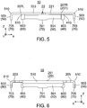
Fig. 5 is a front view showing the antenna ofFig. 1 . -
Fig. 6 is a rear view showing the antenna ofFig. 1 . -
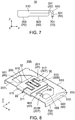
Fig. 7 is a right-side view showing the antenna ofFig. 1 . -
Fig. 8 is a top, perspective view showing an antenna according to a second embodiment of the present invention. -
Fig. 9 is a bottom, perspective view showing the antenna ofFig. 8 . -
Fig. 10 is a top view showing the antenna ofFig. 8 . -
Fig. 11 is a bottom view showing the antenna ofFig. 8 . -
Fig. 12 is a front view showing the antenna ofFig. 8 . -
Fig. 13 is a rear view showing the antenna ofFig. 8 . -
Fig. 14 is a right-side view showing the antenna ofFig. 8 . -
Fig. 15 is a top view showing an antenna disclosed in Patent Document 1. A dielectric layer is hatched. A conductive layer, which is actually hidden by the dielectric layer and invisible, is depicted by a solid line. - While the invention is susceptible to various modifications and alternative forms, specific embodiments thereof are shown by way of example in the drawings and will herein be described in detail. It should be understood, however, that the drawings and detailed description thereto are not intended to limit the invention to the particular form disclosed, but on the contrary, the intention is to cover all modifications, equivalents and alternatives falling within the spirit and scope of the present invention as defined by the appended claims.
- Referring to
Figs. 1 and 2 , anantenna 10 according to a first embodiment of the present invention has a split-ring resonator structure. In detail, theantenna 10 is provided with amain portion 20, a facingportion 30, afirst feeding terminal 40, three second feeding terminals 50 (501, 503, 505), anadditional terminal 60 and three fixed portions 70 (701, 703, 705). As understood fromFigs. 1 and 2 , in the present embodiment, theantenna 10 is a single-piece member which is formed by punching a single metal sheet and bending the punched metal sheet. - Referring to
Figs. 3 and 4 , themain portion 20 has a ring-shape with asplit 22. Here, the "ring-shape" is not limited to a circular-shape but includes other shapes such as an oval-shape, a polygonal-shape and so on. In the present embodiment, themain portion 20 has an approximately rectangular-shape with four sides. Moreover, themain portion 20 has afirst end portion 221 and asecond end portion 223 which form thesplit 22. In detail, themain portion 20 is provided with afirst side portion 201 extending in a lateral direction, asecond side portion 203 and athird side portion 205 which extend forward from both ends of thefirst side portion 201, respectively, and afourth side portion 207 located between a front end portion of thesecond side portion 203 and a front end portion of thethird side portion 205. In the present embodiment, the lateral direction is an X-direction. A front-rear direction is a Y-direction. A negative Y-direction is directed forward while a positive Y-direction is directed rearward. - As shown in
Figs. 3 and 4 , thesplit 22 is formed at the middle of thefourth side portion 207 in the lateral direction. In other words, thefourth side portion 207 is divided in two portions, a fourth sideright part 207R and a fourth side leftpart 207L, by thesplit 22. Thefirst end portion 221 of themain portion 20 is one of end portions of the fourth sideright part 207R while thesecond end portion 223 is one of end portions of the fourth side leftpart 207L. - As shown in
Figs. 1 to 4 , the facingportion 30 is situated between thefirst side portion 201 of themain portion 20 and thefourth side portion 207 of themain portion 20 in the front-rear direction. Moreover, the facingportion 30 is situated between thesecond side portion 203 of themain portion 20 and thethird side portion 205 of themain portion 20 in the lateral direction. In addition, the facingportion 30 is flush with themain portion 20. The facingportion 30 is provided on specific one of the sides of themain portion 20. In more detail, the facingportion 30 is provided on a middle portion of thefourth side portion 207 of themain portion 20. That is, the specific one of the sides is thefourth side portion 207 in the present embodiment. However, the present invention is not limited thereto. The facingportion 30 may be provided so that a distance from the facingportion 30 to thesecond side portion 203 is shorter or longer than a distance from the facingportion 30 to thethird side portion 205. In that modification, thesplit 22 of themain portion 20 would be situated near to one of thesecond side portion 203 and thethird side portion 205. - As shown in
Figs. 3 and 4 , the facingportion 30 is situated between thefirst side portion 201 of themain portion 20 and thefourth side portion 207 of themain portion 20 in the front-rear direction. Moreover, the facingportion 30 is situated between thesecond side portion 203 of themain portion 20 and thethird side portion 205 of themain portion 20 in the lateral direction. In detail, the facingportion 30 has a first facingportion 301 and a second facingportion 303. Then, the first facingportion 301 and the second facingportion 303 are provided on thefirst end portion 221 of themain portion 20 and thesecond end portion 223 of themain portion 20, respectively. The first facingportion 301 and the second facingportion 303 extend rearward from thefirst end portion 221 and thesecond end portion 223, respectively. The first facingportion 301 and the second facingportion 303 are apart from thefirst side portion 201 of themain portion 20, thesecond side portion 203 of themain portion 20 and thethird side portion 205 of themain portion 20. - As shown in
Figs. 3 and 4 , the first facingportion 301 and the second facingportion 303 are arranged apart from each other and face each other. In detail, each of the first facingportion 301 and the second facingportion 303 has a comb-shape. The first facingportion 301 and the second facingportion 303 are arranged with a space left therebetween so that tooth of the first facingportion 301 and tooth of the second facingportion 303 are alternately arranged in the front-rear direction. In other words, the first facingportion 301 and the second facingportion 303 form aninterdigital portion 30, and aninterdigital slot 32 is made between the first facingportion 301 and the second facingportion 303. Thus, the first facingportion 301 and the second facingportion 303 form a capacitor. In the present embodiment, thefirst end portion 221 of themain portion 20 and thesecond end portion 223 of themain portion 20 also form a part of theinterdigital portion 30. On the other hand, themain portion 20 forms an inductor and constitutes an LC resonant circuit in conjunction with the facingportion 30. - As shown in
Figs. 1 to 4 , thefirst feeding terminal 40 is provided on themain portion 20. On themain portion 20, thefirst feeding terminal 40 of the present embodiment is provided nearer to thefirst end portion 221 than any of thesecond feeding terminals 50 is provided. In other words, thefirst feeding terminal 40 is situated between any of thesecond feeding terminals 50 and thefirst end portion 221 on themain portion 20. In detail, thefirst feeding terminal 40 is provided on themain portion 20 so that a current path between thefirst feeding terminal 40 and thefirst end portion 221 is shorter than a current path between thefirst feeding terminal 40 and each of thesecond feeding terminals 50. - As shown in
Figs. 1 to 4 , thefirst feeding terminal 40 is provided on the fourth sideright part 207R of themain portion 20. Thefirst feeding terminal 40 is situated near to thefirst end portion 221 but away from thefirst end portion 221 and the first facingportion 301. In addition, a shortest distance between thefirst feeding terminal 40 and the first facingportion 301 is shorter than a shortest distance between thefirst feeding terminal 40 and thesecond feeding terminal 503. - As shown in
Figs. 2 to 4 , thefirst feeding terminal 40 has afirst part 401 extending from an inside edge of the fourth sideright part 207R of themain portion 20 in an inward direction of themain portion 20 and asecond part 403 extending from an end of thefirst part 401 in an intersecting direction intersecting the inward direction via abent part 410. In the present embodiment, the intersecting direction is directed downward. An up-down direction is a Z-direction in the present embodiment. A positive Z-direction is directed upward while a negative Z-direction is directed downward. - As understood from
Figs. 1 to 4 , theadditional terminal 60 is situated opposite to thefirst feeding terminal 40 across the facingportion 30. In the present embodiment, an arrangement of theadditional terminal 60 and thefirst feeding terminal 40 is symmetrical with respect to the facingportion 30. In other words, theadditional terminal 60 is situated between any of thesecond feeding terminals 50 and thesecond end portion 223 on themain portion 20. In detail, the arrangement of theadditional terminal 60 and thefirst feeding terminal 40 is surface-symmetrical with respect to a plane (hereinafter referred to as a reference plane) perpendicular to the lateral direction and passing through the middle, in the lateral direction, of the facingportion 30. However, the present invention is not limited thereto. The arrangement of theadditional terminal 60 and thefirst feeding terminal 40 may not be symmetrical. - As shown in
Figs. 1 to 4 , theadditional terminal 60 is provided on the fourth side leftpart 207L of themain portion 20 in the present embodiment. Theadditional terminal 60 is provided, on themain portion 20, nearer to thesecond end portion 223 than any one of thesecond feeding terminals 50 is provided. Moreover, theadditional terminal 60 is situated near to thesecond end portion 223 but away from thesecond end portion 223 and the second facingportion 303. In addition, a shortest distance between theadditional terminal 60 and the second facingportion 303 is shorter than a shortest distance between theadditional terminal 60 and thesecond feeding terminal 505. - As shown in
Figs. 2 to 4 , theadditional terminal 60 is formed similarly to thefirst feeding terminal 40. In detail, theadditional terminal 60 has afirst part 601 extending from an inside edge of the fourth side leftpart 207L of themain portion 20 in the inward direction of themain portion 20 and asecond part 603 extending from an end of thefirst part 601 in the intersecting direction intersecting the inward direction via abent part 610. In the present embodiment, thesecond part 603 of theadditional terminal 60 extends downward. However, the present invention is not limited thereto. Theadditional terminal 60 may have a different shape and a different size which are different from those of thefirst feeding terminal 40. Changing one or more of the position, the shape and the size of theadditional terminal 60 allows a resonance frequency of theantenna 10 to be varied. However, it is easy to design theantenna 10 in a case where thefirst feeding terminal 40 and theadditional terminal 60 have the same shape and the same size and are arranged on symmetric positions when compared with other cases. - As shown in
Fig. 2 andFigs. 4 to 7 , each of thesecond feeding terminals main portion 20 via abent part 510. In detail, thesecond feeding terminals first side portion 201 of themain portion 20, thesecond side portion 203 of themain portion 20 and thethird side portion 205 of themain portion 20, respectively, via thebent parts 510. Thesecond feeding terminal 501 has a rectangular plate-shape long in the lateral direction and extends downward. Each of thesecond feeding terminals - As shown in
Fig. 4 , thesecond feeding terminals 50 are arranged to be mirror images of each other with respect to the facingportion 30. In other words, the arrangement of thesecond feeding terminals 50 is symmetrical with respect to the facingportion 30. However, the present invention is not limited thereto. Thesecond feeding terminals 50 may be arranged not to be mirror images of each other with respect to the facingportion 30. Moreover, one of thesecond feeding terminals 50 is essential, and the remains are optional. - As shown in
Fig. 2 andFigs. 4 to 7 , the fixedportions second feeding terminals portions 70 is equal to the number of thesecond feeding terminals 50. However, each of thesecond feeding terminals portions 70. - As understood from
Fig. 2 andFigs. 4 to 7 , the fixedportions second feeding terminals portions second feeding terminals portions second feeding terminals portions first feeding terminal 40 and a position of a lower edge of theadditional terminal 60. - As understood from
Fig. 4 , in the present embodiment, the fixedportions 70 are arranged to be mirror images of each other with respect to the facingportion 30. The arrangement of the fixedportions 70 is symmetrical with respect to the facingportion 30. In detail, the arrangement of the fixedportions 70 is surface-symmetrical with respect to the reference plane. In more detail, the fixedportion 701 has a shape long in the lateral direction and is provided at the middle of thesecond feeding terminal 501 in the lateral direction. Moreover, the fixedportion 703 and the fixedportion 705 have shapes long in the front-rear direction and are provided on a front end portion of thesecond side portion 203 and a front end portion of thethird side portion 205, respectively. However, the present invention is not limited thereto. The arrangement of the fixedportions 70 may be asymmetrical with respect to the facingportion 30. However, symmetrical arrangement of the fixedportions 70 causes uniform deformation of theantenna 10 upon a reflow process, and thereby change of characteristics of theantenna 10 can be suppressed. In addition, when theantenna 10 receives an external force unexpected, the symmetrical arrangement of the fixedportions 70 can disperse the external force appropriately to prevent or restrain deformation of theantenna 10. - The antenna 10 (see
Figs. 1 and 2 ) according to the present embodiment is mounted on an object (not shown). The object is a printed circuit board, for example. The object has an antenna mount surface (not shown), and a plurality of connection pads (not shown) are formed on the antenna mount surface. In addition, the object is provided with a feed line (not shown) to be connected to thefirst feeding terminal 40 of theantenna 10 and a ground plane (not shown) to be connected to thesecond feeding terminals 50. - When the antenna 10 (see
Figs. 1 and 2 ) is mounted on the object, each of thesecond part 403 of thefirst feeding terminal 40, thesecond part 603 of theadditional terminal 60 and the fixedportions 70 is fixed on the connection pad (not shown) corresponding thereto. Thefirst feeding terminal 40 is electrically connected to the feed line (not shown) via the connection pad corresponding thereto. Moreover, thesecond feeding terminals 50 are electrically connected to the ground plane (not shown) via the fixedportions 70 and the connection pads corresponding thereto. With this structure, feeding can be carried out between thefirst feeding terminal 40 and thesecond feeding terminals 50. On the other hand, theadditional terminal 60 is connected to neither the feed line nor the ground plane in the present embodiment. - According to the present embodiment, as understood from
Figs. 3 and 4 , thefirst feeding terminal 40 is provided nearer to the first facingportion 301, and theadditional terminal 60 is provided nearer to the second facingportion 303. In addition, both of thefirst feeding terminal 40 and theadditional terminal 60 are fixed to the object (not shown). With this structure, the fourth sideright part 207R and the fourth side leftpart 207L can be equalized in mechanical strength. In other words, in the reflow process in which theantenna 10 is mounted on the object, an influence on the fourth sideright part 207R and the first facingportion 301 can be balanced with an influence on the fourth side leftpart 207L and the second facingportion 303. As a result, a design of theantenna 10 can be carried out in consideration of change of relative positions of the first facingportion 301 and the second facingportion 303 that is caused by the reflow process so that theantenna 10 having stable characteristics can be obtained. - Referring to
Figs. 8 and9 , anantenna 10A according to the present embodiment is provided with a third facingportion 305 and a fourth facingportion 307 in addition to the same structure as theantenna 10 according to the first embodiment. In the following description, the same reference numerals are used for the same or corresponding components as the first embodiment. - As shown in
Figs. 8 to 11 , the third facingportion 305 has afirst connection portion 311 and afirst comb portion 313. Moreover, the third facingportion 305 has asecond connection portion 315 and asecond comb portion 317. - As understood from
Figs. 8 ,9 and14 , thefirst connection portion 311 has a C-shape when viewed along the lateral direction. In detail, thefirst connection portion 311 extends forward from afirst end portion 221 of amain portion 20, then extends upward, and further extends rearward. Thesecond connection portion 315 has the same shape as thefirst connection portion 311. In detail, thesecond connection portion 315 extends forward from asecond end portion 223 of themain portion 20, then extends upward, and further extends rearward. Thefirst comb portion 313 and thesecond comb portion 317 extend rearward from an end portion of thefirst connection portion 311 and an end portion of thesecond connection portion 315, respectively. - As understood from
Figs. 10 and11 , thefirst comb portion 313 has the same shape and the same size as a first facingportion 301. Moreover, thesecond comb portion 317 has the same shape and the same size as a second facingportion 303. As understood fromFigs. 12 to 14 , thefirst comb portion 313 and thesecond comb portion 317 are flush with each other and arranged in parallel with the first facingportion 301 and the second facingportion 303. Thus, in the present embodiment, a facingportion 30 has a two layer structure. - As understood from
Figs. 8 and9 , the third facingportion 305 and the fourth facingportion 307 form the facing portion (interdigital portion) 30 in conjunction with the first facingportion 301 and the second facingportion 303. With this structure, a capacitance of the capacitor can be increased without increase of a size of theinterdigital portion 30 in a plane perpendicular to the up-down direction. Provided that the resonance frequency of theantenna 10A is constant, increase of the capacitance of the capacitor allows an inductance of themain portion 20 to be reduced. This means that a size of themain portion 20 of theantenna 10A can be reduced in the plane perpendicular to the up-down direction. In other words, a footprint of theantenna 10A on an object (not shown) can be reduced. - As shown in
Figs. 8 to 11 , also in theantenna 10A according to the present embodiment, anadditional terminal 60 is provided opposite to afirst feeding terminal 40 across the facingportion 30, similarly to theantenna 10 according to the first embodiment. In detail, theadditional terminal 60 is provided to be a mirror image of thefirst feeding terminal 40 with respect to the facingportion 30. Accordingly, in a reflow process in which theantenna 10A is mounted on the object (not shown), an influence on a fourth sideright part 207R, the first facingportion 301 and the third facingportion 305 can be balanced with an influence on the fourth side leftpart 207L, the second facingportion 303 and the fourth facingportion 307. Thus, according to the present embodiment, each of a relative positional relationship between the first facingportion 301 and the second facingportion 303 and a relative positional relationship between the third facingportion 305 and the fourth facingportion 307 can be maintained, and thereby theantenna 10A having stable characteristics can be obtained. - While there has been described what is believed to be the preferred embodiment of the invention, those skilled in the art will recognize that other and further modifications may be made thereto without departing from the spirit of the invention, and it is intended to claim all such embodiments that fall within the true scope of the invention. For example, although the facing
portion 30 has the two layer structure in the second embodiment, the facingportion 30 may have three or more layer structure. In addition, although the third facingportion 305 and the fourth facingportion 307 are arranged above the first facingportion 301 and the second facingportion 303, respectively, in the up-down direction in the second embodiment, the third facingportion 305 and the fourth facingportion 307 may be arranged below the first facingportion 301 and the second facingportion 303, respectively, in the up-down direction.
Claims (8)
- An antenna mountable on an object, wherein:the antenna comprises a main portion, a facing portion, a first feeding terminal, a second feeding terminal and an additional terminal;the main portion has a ring-shape with a split and has a first end portion and a second end portion which form the split;the facing portion has a first facing portion provided on the first end portion and a second facing portion provided on the second end portion;the first facing portion and the second facing portion arranged apart from each other and face each other;the first feeding terminal, the second feed terminal and the additional terminal are provided on the main portion and are parts which are fixed to the object when the antenna is mounted on the object;the first feeding terminal is situated nearer to the first end portion on the main portion than the second feeding terminal is situated; andthe additional terminal is situated nearer to the second end portion on the main portion than the second feeding terminal is situated.
- The antenna as recited in claim 1, wherein:the additional terminal and the second facing portion has a first shortest distance therebetween while the additional terminal and the second feeding terminal has a second shortest distance therebetween; andthe first shortest distance is shorter than the second shortest distance.
- The antenna as recited in claim 1 or 2, wherein:the first feeding terminal is provided apart from the first end portion and the first facing portion; andthe additional terminal is provided apart from the second end portion and the second facing portion.
- The antenna as recited in any one of claims 1 to 3, wherein:each of the first feeding terminal and the additional terminal has a first part extending in an inward direction directed inward of the main portion from the main portion and a second part extending from an end of the first part in an intersecting direction intersecting with the inward direction; andthe second part is fixed to the object when the antenna is mounted on the object.
- The antenna as recited in any one of claims 1 to 4, wherein:the main portion has an approximately rectangular ring-shape having four sides; andthe facing portion is provided on specific one of the four sides.
- The antenna as recited in claim 5, wherein
the first feeding terminal and the additional terminal extend from the specific one of the four sides. - The antenna as recited in any one of claims 1 to 6, wherein;
each of the first facing portion and the second facing portion has a comb-shape; and
the first facing portion and the second facing portion form an interdigital slot therebetween. - The antenna as recited in any one of claims 1 to 7, wherein
the antenna is made of a single metal sheet having a plurality of bent parts.
Applications Claiming Priority (1)
| Application Number | Priority Date | Filing Date | Title |
|---|---|---|---|
| JP2019039447A JP7216576B2 (en) | 2019-03-05 | 2019-03-05 | antenna |
Publications (2)
| Publication Number | Publication Date |
|---|---|
| EP3706240A1 true EP3706240A1 (en) | 2020-09-09 |
| EP3706240B1 EP3706240B1 (en) | 2022-03-23 |
Family
ID=69156320
Family Applications (1)
| Application Number | Title | Priority Date | Filing Date |
|---|---|---|---|
| EP20150934.6A Active EP3706240B1 (en) | 2019-03-05 | 2020-01-09 | Antenna |
Country Status (6)
| Country | Link |
|---|---|
| US (1) | US11223115B2 (en) |
| EP (1) | EP3706240B1 (en) |
| JP (1) | JP7216576B2 (en) |
| KR (1) | KR102341622B1 (en) |
| CN (1) | CN111668587B (en) |
| TW (1) | TWI721746B (en) |
Families Citing this family (10)
| Publication number | Priority date | Publication date | Assignee | Title |
|---|---|---|---|---|
| JP7216577B2 (en) * | 2019-03-05 | 2023-02-01 | 日本航空電子工業株式会社 | antenna |
| JP7623140B2 (en) * | 2021-01-14 | 2025-01-28 | 日本航空電子工業株式会社 | Antenna member and assembly |
| JP1701515S (en) * | 2021-03-17 | 2021-12-06 | ||
| JP7608267B2 (en) * | 2021-05-19 | 2025-01-06 | 日本航空電子工業株式会社 | Multi-band Antennas |
| JP7764226B2 (en) * | 2021-12-06 | 2025-11-05 | 日本航空電子工業株式会社 | Antenna device |
| JP7748911B2 (en) * | 2022-04-18 | 2025-10-03 | 日本航空電子工業株式会社 | Multi-band Antenna |
| TWD226288S (en) * | 2022-10-26 | 2023-07-01 | 大陸商昆山聯滔電子有限公司 | Antenna |
| US12596365B2 (en) * | 2023-05-09 | 2026-04-07 | T-Mobile Usa, Inc. | Enhancements to beyond-visual-line-of-sight (BVLOS) operation of remote-controlled apparatuses |
| USD1075731S1 (en) * | 2023-12-29 | 2025-05-20 | Autel Robotics Co., Ltd. | Antenna |
| USD1113884S1 (en) * | 2024-03-05 | 2026-02-17 | Japan Aviation Electronics Industry, Limited | Antenna |
Citations (4)
| Publication number | Priority date | Publication date | Assignee | Title |
|---|---|---|---|---|
| US20060001575A1 (en) * | 2004-06-30 | 2006-01-05 | Young-Min Jo | Low profile compact multi-band meanderline loaded antenna |
| US20160294048A1 (en) * | 2014-03-13 | 2016-10-06 | Huawei Device Co., Ltd | Antenna and Terminal |
| JP2016225956A (en) | 2015-06-04 | 2016-12-28 | 日本電気株式会社 | Antenna and radio communication equipment |
| US20170301997A1 (en) * | 2014-09-26 | 2017-10-19 | Nec Corporation | Antenna array, wireless communication apparatus, and method for making antenna array |
Family Cites Families (18)
| Publication number | Priority date | Publication date | Assignee | Title |
|---|---|---|---|---|
| CA1336618C (en) | 1981-03-11 | 1995-08-08 | Huw David Rees | Electromagnetic radiation sensors |
| FI115342B (en) | 2001-11-15 | 2005-04-15 | Filtronic Lk Oy | Process for producing an internal antenna and antenna element |
| US7525711B1 (en) | 2005-08-31 | 2009-04-28 | The United States Of America As Represented By The Secretary Of The Navy | Actively tunable electromagnetic metamaterial |
| JP2007221774A (en) | 2006-01-23 | 2007-08-30 | Yokowo Co Ltd | Plane type antenna |
| KR100980218B1 (en) | 2008-03-31 | 2010-09-06 | 주식회사 에이스테크놀로지 | Internal Antenna Providing Impedance Maching for Multi Band |
| WO2010055945A1 (en) * | 2008-11-17 | 2010-05-20 | 株式会社村田製作所 | Antenna and wireless ic device |
| KR20140027246A (en) | 2011-04-25 | 2014-03-06 | 어플라이드 머티어리얼스, 인코포레이티드 | Apparatus and methods for microwave processing of semiconductor substrates |
| CN103620870B (en) | 2011-06-23 | 2017-02-15 | 加利福尼亚大学董事会 | Small Electrical Vertical Split Ring Resonator Antenna |
| CN102891352B (en) | 2011-07-19 | 2015-04-29 | 深圳市信维通信股份有限公司 | Antenna unit, antenna and antenna matching device with antenna unit |
| US20140167525A1 (en) | 2011-08-16 | 2014-06-19 | Koninklijke Philips N.V. | Techniques for efficient power transfers in a capacitive wireless powering system |
| KR101874892B1 (en) | 2012-01-13 | 2018-07-05 | 삼성전자 주식회사 | Small antenna appartus and method for controling a resonance frequency of small antenna |
| JP5772868B2 (en) * | 2012-05-21 | 2015-09-02 | 株式会社村田製作所 | ANTENNA DEVICE AND WIRELESS COMMUNICATION DEVICE |
| JP5726983B2 (en) * | 2013-10-30 | 2015-06-03 | 太陽誘電株式会社 | Chip antenna device and transmission / reception communication circuit board |
| US9484631B1 (en) * | 2014-12-01 | 2016-11-01 | Amazon Technologies, Inc. | Split band antenna design |
| TWI662741B (en) | 2015-01-23 | 2019-06-11 | 群邁通訊股份有限公司 | Antenna structure and wireless communication device having the same |
| CN105024150B (en) | 2015-05-11 | 2018-02-06 | 云南大学 | A kind of tri-band antenna applied to WLAN and WiMAX |
| US10389161B2 (en) * | 2017-03-15 | 2019-08-20 | Energous Corporation | Surface mount dielectric antennas for wireless power transmitters |
| JP2019213011A (en) * | 2018-06-01 | 2019-12-12 | 東芝テック株式会社 | Antenna device and communication device |
-
2019
- 2019-03-05 JP JP2019039447A patent/JP7216576B2/en active Active
-
2020
- 2020-01-02 TW TW109100031A patent/TWI721746B/en active
- 2020-01-08 US US16/736,909 patent/US11223115B2/en active Active
- 2020-01-09 EP EP20150934.6A patent/EP3706240B1/en active Active
- 2020-01-15 KR KR1020200005207A patent/KR102341622B1/en active Active
- 2020-01-17 CN CN202010053176.9A patent/CN111668587B/en active Active
Patent Citations (4)
| Publication number | Priority date | Publication date | Assignee | Title |
|---|---|---|---|---|
| US20060001575A1 (en) * | 2004-06-30 | 2006-01-05 | Young-Min Jo | Low profile compact multi-band meanderline loaded antenna |
| US20160294048A1 (en) * | 2014-03-13 | 2016-10-06 | Huawei Device Co., Ltd | Antenna and Terminal |
| US20170301997A1 (en) * | 2014-09-26 | 2017-10-19 | Nec Corporation | Antenna array, wireless communication apparatus, and method for making antenna array |
| JP2016225956A (en) | 2015-06-04 | 2016-12-28 | 日本電気株式会社 | Antenna and radio communication equipment |
Also Published As
| Publication number | Publication date |
|---|---|
| TWI721746B (en) | 2021-03-11 |
| US11223115B2 (en) | 2022-01-11 |
| KR20200106818A (en) | 2020-09-15 |
| JP7216576B2 (en) | 2023-02-01 |
| KR102341622B1 (en) | 2021-12-20 |
| US20200287276A1 (en) | 2020-09-10 |
| CN111668587B (en) | 2022-01-25 |
| EP3706240B1 (en) | 2022-03-23 |
| JP2020145541A (en) | 2020-09-10 |
| TW202034577A (en) | 2020-09-16 |
| CN111668587A (en) | 2020-09-15 |
Similar Documents
| Publication | Publication Date | Title |
|---|---|---|
| EP3706240B1 (en) | Antenna | |
| CN111668586B (en) | Antenna with a shield | |
| JP7196008B2 (en) | antenna | |
| US20230064606A1 (en) | Connector, connector module, and electronic apparatus | |
| US20210126373A1 (en) | Antenna | |
| CN113939955B (en) | antenna | |
| US11417957B2 (en) | Antenna | |
| JP6911091B2 (en) | Connector and electronics | |
| US12218442B2 (en) | Antenna device for vehicle | |
| US11063360B2 (en) | Antenna | |
| WO2021132187A1 (en) | Connector, connector module, and electronic equipment | |
| WO2021132188A1 (en) | Connector and electronic device | |
| EP3876342A1 (en) | Split ring resonator and communication device | |
| EP4471986A1 (en) | Antenna element and antenna device - ep | |
| JP7623140B2 (en) | Antenna member and assembly | |
| US12347943B2 (en) | Multiband antenna |
Legal Events
| Date | Code | Title | Description |
|---|---|---|---|
| PUAI | Public reference made under article 153(3) epc to a published international application that has entered the european phase |
Free format text: ORIGINAL CODE: 0009012 |
|
| STAA | Information on the status of an ep patent application or granted ep patent |
Free format text: STATUS: THE APPLICATION HAS BEEN PUBLISHED |
|
| AK | Designated contracting states |
Kind code of ref document: A1 Designated state(s): AL AT BE BG CH CY CZ DE DK EE ES FI FR GB GR HR HU IE IS IT LI LT LU LV MC MK MT NL NO PL PT RO RS SE SI SK SM TR |
|
| AX | Request for extension of the european patent |
Extension state: BA ME |
|
| STAA | Information on the status of an ep patent application or granted ep patent |
Free format text: STATUS: REQUEST FOR EXAMINATION WAS MADE |
|
| 17P | Request for examination filed |
Effective date: 20210204 |
|
| RBV | Designated contracting states (corrected) |
Designated state(s): AL AT BE BG CH CY CZ DE DK EE ES FI FR GB GR HR HU IE IS IT LI LT LU LV MC MK MT NL NO PL PT RO RS SE SI SK SM TR |
|
| STAA | Information on the status of an ep patent application or granted ep patent |
Free format text: STATUS: EXAMINATION IS IN PROGRESS |
|
| 17Q | First examination report despatched |
Effective date: 20210420 |
|
| GRAP | Despatch of communication of intention to grant a patent |
Free format text: ORIGINAL CODE: EPIDOSNIGR1 |
|
| STAA | Information on the status of an ep patent application or granted ep patent |
Free format text: STATUS: GRANT OF PATENT IS INTENDED |
|
| INTG | Intention to grant announced |
Effective date: 20211026 |
|
| GRAS | Grant fee paid |
Free format text: ORIGINAL CODE: EPIDOSNIGR3 |
|
| GRAA | (expected) grant |
Free format text: ORIGINAL CODE: 0009210 |
|
| STAA | Information on the status of an ep patent application or granted ep patent |
Free format text: STATUS: THE PATENT HAS BEEN GRANTED |
|
| AK | Designated contracting states |
Kind code of ref document: B1 Designated state(s): AL AT BE BG CH CY CZ DE DK EE ES FI FR GB GR HR HU IE IS IT LI LT LU LV MC MK MT NL NO PL PT RO RS SE SI SK SM TR |
|
| REG | Reference to a national code |
Ref country code: GB Ref legal event code: FG4D |
|
| REG | Reference to a national code |
Ref country code: CH Ref legal event code: EP |
|
| REG | Reference to a national code |
Ref country code: IE Ref legal event code: FG4D |
|
| REG | Reference to a national code |
Ref country code: DE Ref legal event code: R096 Ref document number: 602020002259 Country of ref document: DE |
|
| REG | Reference to a national code |
Ref country code: AT Ref legal event code: REF Ref document number: 1478087 Country of ref document: AT Kind code of ref document: T Effective date: 20220415 |
|
| REG | Reference to a national code |
Ref country code: LT Ref legal event code: MG9D |
|
| REG | Reference to a national code |
Ref country code: NL Ref legal event code: MP Effective date: 20220323 |
|
| PG25 | Lapsed in a contracting state [announced via postgrant information from national office to epo] |
Ref country code: SE Free format text: LAPSE BECAUSE OF FAILURE TO SUBMIT A TRANSLATION OF THE DESCRIPTION OR TO PAY THE FEE WITHIN THE PRESCRIBED TIME-LIMIT Effective date: 20220323 Ref country code: RS Free format text: LAPSE BECAUSE OF FAILURE TO SUBMIT A TRANSLATION OF THE DESCRIPTION OR TO PAY THE FEE WITHIN THE PRESCRIBED TIME-LIMIT Effective date: 20220323 Ref country code: NO Free format text: LAPSE BECAUSE OF FAILURE TO SUBMIT A TRANSLATION OF THE DESCRIPTION OR TO PAY THE FEE WITHIN THE PRESCRIBED TIME-LIMIT Effective date: 20220623 Ref country code: LT Free format text: LAPSE BECAUSE OF FAILURE TO SUBMIT A TRANSLATION OF THE DESCRIPTION OR TO PAY THE FEE WITHIN THE PRESCRIBED TIME-LIMIT Effective date: 20220323 Ref country code: HR Free format text: LAPSE BECAUSE OF FAILURE TO SUBMIT A TRANSLATION OF THE DESCRIPTION OR TO PAY THE FEE WITHIN THE PRESCRIBED TIME-LIMIT Effective date: 20220323 Ref country code: BG Free format text: LAPSE BECAUSE OF FAILURE TO SUBMIT A TRANSLATION OF THE DESCRIPTION OR TO PAY THE FEE WITHIN THE PRESCRIBED TIME-LIMIT Effective date: 20220623 |
|
| REG | Reference to a national code |
Ref country code: AT Ref legal event code: MK05 Ref document number: 1478087 Country of ref document: AT Kind code of ref document: T Effective date: 20220323 |
|
| PG25 | Lapsed in a contracting state [announced via postgrant information from national office to epo] |
Ref country code: LV Free format text: LAPSE BECAUSE OF FAILURE TO SUBMIT A TRANSLATION OF THE DESCRIPTION OR TO PAY THE FEE WITHIN THE PRESCRIBED TIME-LIMIT Effective date: 20220323 Ref country code: GR Free format text: LAPSE BECAUSE OF FAILURE TO SUBMIT A TRANSLATION OF THE DESCRIPTION OR TO PAY THE FEE WITHIN THE PRESCRIBED TIME-LIMIT Effective date: 20220624 Ref country code: FI Free format text: LAPSE BECAUSE OF FAILURE TO SUBMIT A TRANSLATION OF THE DESCRIPTION OR TO PAY THE FEE WITHIN THE PRESCRIBED TIME-LIMIT Effective date: 20220323 |
|
| PG25 | Lapsed in a contracting state [announced via postgrant information from national office to epo] |
Ref country code: NL Free format text: LAPSE BECAUSE OF FAILURE TO SUBMIT A TRANSLATION OF THE DESCRIPTION OR TO PAY THE FEE WITHIN THE PRESCRIBED TIME-LIMIT Effective date: 20220323 |
|
| PG25 | Lapsed in a contracting state [announced via postgrant information from national office to epo] |
Ref country code: SM Free format text: LAPSE BECAUSE OF FAILURE TO SUBMIT A TRANSLATION OF THE DESCRIPTION OR TO PAY THE FEE WITHIN THE PRESCRIBED TIME-LIMIT Effective date: 20220323 Ref country code: SK Free format text: LAPSE BECAUSE OF FAILURE TO SUBMIT A TRANSLATION OF THE DESCRIPTION OR TO PAY THE FEE WITHIN THE PRESCRIBED TIME-LIMIT Effective date: 20220323 Ref country code: RO Free format text: LAPSE BECAUSE OF FAILURE TO SUBMIT A TRANSLATION OF THE DESCRIPTION OR TO PAY THE FEE WITHIN THE PRESCRIBED TIME-LIMIT Effective date: 20220323 Ref country code: PT Free format text: LAPSE BECAUSE OF FAILURE TO SUBMIT A TRANSLATION OF THE DESCRIPTION OR TO PAY THE FEE WITHIN THE PRESCRIBED TIME-LIMIT Effective date: 20220725 Ref country code: ES Free format text: LAPSE BECAUSE OF FAILURE TO SUBMIT A TRANSLATION OF THE DESCRIPTION OR TO PAY THE FEE WITHIN THE PRESCRIBED TIME-LIMIT Effective date: 20220323 Ref country code: EE Free format text: LAPSE BECAUSE OF FAILURE TO SUBMIT A TRANSLATION OF THE DESCRIPTION OR TO PAY THE FEE WITHIN THE PRESCRIBED TIME-LIMIT Effective date: 20220323 Ref country code: CZ Free format text: LAPSE BECAUSE OF FAILURE TO SUBMIT A TRANSLATION OF THE DESCRIPTION OR TO PAY THE FEE WITHIN THE PRESCRIBED TIME-LIMIT Effective date: 20220323 Ref country code: AT Free format text: LAPSE BECAUSE OF FAILURE TO SUBMIT A TRANSLATION OF THE DESCRIPTION OR TO PAY THE FEE WITHIN THE PRESCRIBED TIME-LIMIT Effective date: 20220323 |
|
| PG25 | Lapsed in a contracting state [announced via postgrant information from national office to epo] |
Ref country code: PL Free format text: LAPSE BECAUSE OF FAILURE TO SUBMIT A TRANSLATION OF THE DESCRIPTION OR TO PAY THE FEE WITHIN THE PRESCRIBED TIME-LIMIT Effective date: 20220323 Ref country code: IS Free format text: LAPSE BECAUSE OF FAILURE TO SUBMIT A TRANSLATION OF THE DESCRIPTION OR TO PAY THE FEE WITHIN THE PRESCRIBED TIME-LIMIT Effective date: 20220723 Ref country code: AL Free format text: LAPSE BECAUSE OF FAILURE TO SUBMIT A TRANSLATION OF THE DESCRIPTION OR TO PAY THE FEE WITHIN THE PRESCRIBED TIME-LIMIT Effective date: 20220323 |
|
| REG | Reference to a national code |
Ref country code: DE Ref legal event code: R097 Ref document number: 602020002259 Country of ref document: DE |
|
| PLBE | No opposition filed within time limit |
Free format text: ORIGINAL CODE: 0009261 |
|
| STAA | Information on the status of an ep patent application or granted ep patent |
Free format text: STATUS: NO OPPOSITION FILED WITHIN TIME LIMIT |
|
| PG25 | Lapsed in a contracting state [announced via postgrant information from national office to epo] |
Ref country code: DK Free format text: LAPSE BECAUSE OF FAILURE TO SUBMIT A TRANSLATION OF THE DESCRIPTION OR TO PAY THE FEE WITHIN THE PRESCRIBED TIME-LIMIT Effective date: 20220323 |
|
| 26N | No opposition filed |
Effective date: 20230102 |
|
| PG25 | Lapsed in a contracting state [announced via postgrant information from national office to epo] |
Ref country code: SI Free format text: LAPSE BECAUSE OF FAILURE TO SUBMIT A TRANSLATION OF THE DESCRIPTION OR TO PAY THE FEE WITHIN THE PRESCRIBED TIME-LIMIT Effective date: 20220323 |
|
| PG25 | Lapsed in a contracting state [announced via postgrant information from national office to epo] |
Ref country code: IT Free format text: LAPSE BECAUSE OF FAILURE TO SUBMIT A TRANSLATION OF THE DESCRIPTION OR TO PAY THE FEE WITHIN THE PRESCRIBED TIME-LIMIT Effective date: 20220323 |
|
| REG | Reference to a national code |
Ref country code: CH Ref legal event code: PL |
|
| PG25 | Lapsed in a contracting state [announced via postgrant information from national office to epo] |
Ref country code: LU Free format text: LAPSE BECAUSE OF NON-PAYMENT OF DUE FEES Effective date: 20230109 |
|
| REG | Reference to a national code |
Ref country code: BE Ref legal event code: MM Effective date: 20230131 |
|
| PG25 | Lapsed in a contracting state [announced via postgrant information from national office to epo] |
Ref country code: LI Free format text: LAPSE BECAUSE OF NON-PAYMENT OF DUE FEES Effective date: 20230131 Ref country code: CH Free format text: LAPSE BECAUSE OF NON-PAYMENT OF DUE FEES Effective date: 20230131 |
|
| PG25 | Lapsed in a contracting state [announced via postgrant information from national office to epo] |
Ref country code: BE Free format text: LAPSE BECAUSE OF NON-PAYMENT OF DUE FEES Effective date: 20230131 |
|
| PG25 | Lapsed in a contracting state [announced via postgrant information from national office to epo] |
Ref country code: IE Free format text: LAPSE BECAUSE OF NON-PAYMENT OF DUE FEES Effective date: 20230109 |
|
| PG25 | Lapsed in a contracting state [announced via postgrant information from national office to epo] |
Ref country code: MC Free format text: LAPSE BECAUSE OF FAILURE TO SUBMIT A TRANSLATION OF THE DESCRIPTION OR TO PAY THE FEE WITHIN THE PRESCRIBED TIME-LIMIT Effective date: 20220323 |
|
| PG25 | Lapsed in a contracting state [announced via postgrant information from national office to epo] |
Ref country code: MC Free format text: LAPSE BECAUSE OF FAILURE TO SUBMIT A TRANSLATION OF THE DESCRIPTION OR TO PAY THE FEE WITHIN THE PRESCRIBED TIME-LIMIT Effective date: 20220323 |
|
| PG25 | Lapsed in a contracting state [announced via postgrant information from national office to epo] |
Ref country code: CY Free format text: LAPSE BECAUSE OF FAILURE TO SUBMIT A TRANSLATION OF THE DESCRIPTION OR TO PAY THE FEE WITHIN THE PRESCRIBED TIME-LIMIT; INVALID AB INITIO Effective date: 20200109 |
|
| PG25 | Lapsed in a contracting state [announced via postgrant information from national office to epo] |
Ref country code: HU Free format text: LAPSE BECAUSE OF FAILURE TO SUBMIT A TRANSLATION OF THE DESCRIPTION OR TO PAY THE FEE WITHIN THE PRESCRIBED TIME-LIMIT; INVALID AB INITIO Effective date: 20200109 |
|
| PG25 | Lapsed in a contracting state [announced via postgrant information from national office to epo] |
Ref country code: TR Free format text: LAPSE BECAUSE OF FAILURE TO SUBMIT A TRANSLATION OF THE DESCRIPTION OR TO PAY THE FEE WITHIN THE PRESCRIBED TIME-LIMIT Effective date: 20220323 |
|
| PGFP | Annual fee paid to national office [announced via postgrant information from national office to epo] |
Ref country code: GB Payment date: 20251127 Year of fee payment: 7 |
|
| PGFP | Annual fee paid to national office [announced via postgrant information from national office to epo] |
Ref country code: FR Payment date: 20251128 Year of fee payment: 7 |
|
| PGFP | Annual fee paid to national office [announced via postgrant information from national office to epo] |
Ref country code: DE Payment date: 20251203 Year of fee payment: 7 |