EP3706232A1 - Non-aqueous electrolyte secondary cell - Google Patents
Non-aqueous electrolyte secondary cell Download PDFInfo
- Publication number
- EP3706232A1 EP3706232A1 EP18873913.0A EP18873913A EP3706232A1 EP 3706232 A1 EP3706232 A1 EP 3706232A1 EP 18873913 A EP18873913 A EP 18873913A EP 3706232 A1 EP3706232 A1 EP 3706232A1
- Authority
- EP
- European Patent Office
- Prior art keywords
- positive electrode
- negative electrode
- lithium
- electrode
- aqueous electrolyte
- Prior art date
- Legal status (The legal status is an assumption and is not a legal conclusion. Google has not performed a legal analysis and makes no representation as to the accuracy of the status listed.)
- Pending
Links
- 239000011255 nonaqueous electrolyte Substances 0.000 title claims abstract description 58
- 229910052744 lithium Inorganic materials 0.000 claims abstract description 101
- WHXSMMKQMYFTQS-UHFFFAOYSA-N Lithium Chemical compound [Li] WHXSMMKQMYFTQS-UHFFFAOYSA-N 0.000 claims abstract description 62
- 239000007774 positive electrode material Substances 0.000 claims abstract description 17
- 229910000314 transition metal oxide Inorganic materials 0.000 claims abstract description 17
- 229910052723 transition metal Inorganic materials 0.000 claims abstract description 15
- 150000003624 transition metals Chemical class 0.000 claims abstract description 15
- RYGMFSIKBFXOCR-UHFFFAOYSA-N Copper Chemical group [Cu] RYGMFSIKBFXOCR-UHFFFAOYSA-N 0.000 claims description 14
- 239000011889 copper foil Substances 0.000 claims description 10
- 238000007599 discharging Methods 0.000 abstract 1
- 239000010410 layer Substances 0.000 description 56
- 239000000203 mixture Substances 0.000 description 47
- 238000004804 winding Methods 0.000 description 17
- 239000007784 solid electrolyte Substances 0.000 description 14
- 238000000151 deposition Methods 0.000 description 11
- 229910052751 metal Inorganic materials 0.000 description 11
- PXHVJJICTQNCMI-UHFFFAOYSA-N Nickel Chemical compound [Ni] PXHVJJICTQNCMI-UHFFFAOYSA-N 0.000 description 10
- -1 polytetrafluoroethylene Polymers 0.000 description 10
- 238000007789 sealing Methods 0.000 description 10
- 229910052782 aluminium Inorganic materials 0.000 description 9
- 230000000052 comparative effect Effects 0.000 description 9
- 239000002184 metal Substances 0.000 description 9
- 230000008021 deposition Effects 0.000 description 8
- 238000004519 manufacturing process Methods 0.000 description 8
- OKTJSMMVPCPJKN-UHFFFAOYSA-N Carbon Chemical compound [C] OKTJSMMVPCPJKN-UHFFFAOYSA-N 0.000 description 7
- XAGFODPZIPBFFR-UHFFFAOYSA-N aluminium Chemical compound [Al] XAGFODPZIPBFFR-UHFFFAOYSA-N 0.000 description 7
- 239000010408 film Substances 0.000 description 7
- 239000011248 coating agent Substances 0.000 description 6
- 238000000576 coating method Methods 0.000 description 6
- 230000000694 effects Effects 0.000 description 6
- 239000008151 electrolyte solution Substances 0.000 description 6
- 238000011156 evaluation Methods 0.000 description 6
- 239000011888 foil Substances 0.000 description 6
- 229920005989 resin Polymers 0.000 description 6
- 239000011347 resin Substances 0.000 description 6
- RTZKZFJDLAIYFH-UHFFFAOYSA-N Diethyl ether Chemical compound CCOCC RTZKZFJDLAIYFH-UHFFFAOYSA-N 0.000 description 5
- HBBGRARXTFLTSG-UHFFFAOYSA-N Lithium ion Chemical compound [Li+] HBBGRARXTFLTSG-UHFFFAOYSA-N 0.000 description 5
- 229910019142 PO4 Inorganic materials 0.000 description 5
- UCKMPCXJQFINFW-UHFFFAOYSA-N Sulphide Chemical compound [S-2] UCKMPCXJQFINFW-UHFFFAOYSA-N 0.000 description 5
- 239000003125 aqueous solvent Substances 0.000 description 5
- 239000010949 copper Substances 0.000 description 5
- 239000013078 crystal Substances 0.000 description 5
- 230000007423 decrease Effects 0.000 description 5
- 229910001416 lithium ion Inorganic materials 0.000 description 5
- 229910052759 nickel Inorganic materials 0.000 description 5
- NBIIXXVUZAFLBC-UHFFFAOYSA-K phosphate Chemical compound [O-]P([O-])([O-])=O NBIIXXVUZAFLBC-UHFFFAOYSA-K 0.000 description 5
- 239000010452 phosphate Substances 0.000 description 5
- YEJRWHAVMIAJKC-UHFFFAOYSA-N 4-Butyrolactone Chemical compound O=C1CCCO1 YEJRWHAVMIAJKC-UHFFFAOYSA-N 0.000 description 4
- SBLRHMKNNHXPHG-UHFFFAOYSA-N 4-fluoro-1,3-dioxolan-2-one Chemical compound FC1COC(=O)O1 SBLRHMKNNHXPHG-UHFFFAOYSA-N 0.000 description 4
- KMTRUDSVKNLOMY-UHFFFAOYSA-N Ethylene carbonate Chemical compound O=C1OCCO1 KMTRUDSVKNLOMY-UHFFFAOYSA-N 0.000 description 4
- SECXISVLQFMRJM-UHFFFAOYSA-N N-Methylpyrrolidone Chemical compound CN1CCCC1=O SECXISVLQFMRJM-UHFFFAOYSA-N 0.000 description 4
- 239000002033 PVDF binder Substances 0.000 description 4
- 239000006230 acetylene black Substances 0.000 description 4
- 239000011230 binding agent Substances 0.000 description 4
- 229910052802 copper Inorganic materials 0.000 description 4
- 150000002148 esters Chemical class 0.000 description 4
- 238000009830 intercalation Methods 0.000 description 4
- 229920002981 polyvinylidene fluoride Polymers 0.000 description 4
- 239000002002 slurry Substances 0.000 description 4
- 230000008961 swelling Effects 0.000 description 4
- VAYTZRYEBVHVLE-UHFFFAOYSA-N 1,3-dioxol-2-one Chemical compound O=C1OC=CO1 VAYTZRYEBVHVLE-UHFFFAOYSA-N 0.000 description 3
- UZKWTJUDCOPSNM-UHFFFAOYSA-N 1-ethenoxybutane Chemical compound CCCCOC=C UZKWTJUDCOPSNM-UHFFFAOYSA-N 0.000 description 3
- WEVYAHXRMPXWCK-UHFFFAOYSA-N Acetonitrile Chemical compound CC#N WEVYAHXRMPXWCK-UHFFFAOYSA-N 0.000 description 3
- XEKOWRVHYACXOJ-UHFFFAOYSA-N Ethyl acetate Chemical compound CCOC(C)=O XEKOWRVHYACXOJ-UHFFFAOYSA-N 0.000 description 3
- XEEYBQQBJWHFJM-UHFFFAOYSA-N Iron Chemical compound [Fe] XEEYBQQBJWHFJM-UHFFFAOYSA-N 0.000 description 3
- 229910001290 LiPF6 Inorganic materials 0.000 description 3
- ZMXDDKWLCZADIW-UHFFFAOYSA-N N,N-Dimethylformamide Chemical compound CN(C)C=O ZMXDDKWLCZADIW-UHFFFAOYSA-N 0.000 description 3
- 239000004698 Polyethylene Substances 0.000 description 3
- 238000004458 analytical method Methods 0.000 description 3
- 150000001875 compounds Chemical class 0.000 description 3
- 239000006258 conductive agent Substances 0.000 description 3
- 239000003792 electrolyte Substances 0.000 description 3
- 239000010439 graphite Substances 0.000 description 3
- 229910002804 graphite Inorganic materials 0.000 description 3
- 230000002687 intercalation Effects 0.000 description 3
- 239000011572 manganese Substances 0.000 description 3
- 239000012046 mixed solvent Substances 0.000 description 3
- 239000007773 negative electrode material Substances 0.000 description 3
- 229920000573 polyethylene Polymers 0.000 description 3
- YLQBMQCUIZJEEH-UHFFFAOYSA-N tetrahydrofuran Natural products C=1C=COC=1 YLQBMQCUIZJEEH-UHFFFAOYSA-N 0.000 description 3
- DHKHKXVYLBGOIT-UHFFFAOYSA-N 1,1-Diethoxyethane Chemical compound CCOC(C)OCC DHKHKXVYLBGOIT-UHFFFAOYSA-N 0.000 description 2
- VQKFNUFAXTZWDK-UHFFFAOYSA-N 2-Methylfuran Chemical compound CC1=CC=CO1 VQKFNUFAXTZWDK-UHFFFAOYSA-N 0.000 description 2
- OIFBSDVPJOWBCH-UHFFFAOYSA-N Diethyl carbonate Chemical compound CCOC(=O)OCC OIFBSDVPJOWBCH-UHFFFAOYSA-N 0.000 description 2
- XTHFKEDIFFGKHM-UHFFFAOYSA-N Dimethoxyethane Chemical compound COCCOC XTHFKEDIFFGKHM-UHFFFAOYSA-N 0.000 description 2
- CPLXHLVBOLITMK-UHFFFAOYSA-N Magnesium oxide Chemical compound [Mg]=O CPLXHLVBOLITMK-UHFFFAOYSA-N 0.000 description 2
- RJUFJBKOKNCXHH-UHFFFAOYSA-N Methyl propionate Chemical compound CCC(=O)OC RJUFJBKOKNCXHH-UHFFFAOYSA-N 0.000 description 2
- 239000004743 Polypropylene Substances 0.000 description 2
- VYPSYNLAJGMNEJ-UHFFFAOYSA-N Silicium dioxide Chemical compound O=[Si]=O VYPSYNLAJGMNEJ-UHFFFAOYSA-N 0.000 description 2
- WYURNTSHIVDZCO-UHFFFAOYSA-N Tetrahydrofuran Chemical compound C1CCOC1 WYURNTSHIVDZCO-UHFFFAOYSA-N 0.000 description 2
- 150000001336 alkenes Chemical class 0.000 description 2
- RDOXTESZEPMUJZ-UHFFFAOYSA-N anisole Chemical compound COC1=CC=CC=C1 RDOXTESZEPMUJZ-UHFFFAOYSA-N 0.000 description 2
- 239000011575 calcium Substances 0.000 description 2
- 239000006229 carbon black Substances 0.000 description 2
- 239000011651 chromium Substances 0.000 description 2
- 229910017052 cobalt Inorganic materials 0.000 description 2
- 239000010941 cobalt Substances 0.000 description 2
- GUTLYIVDDKVIGB-UHFFFAOYSA-N cobalt atom Chemical compound [Co] GUTLYIVDDKVIGB-UHFFFAOYSA-N 0.000 description 2
- MHDVGSVTJDSBDK-UHFFFAOYSA-N dibenzyl ether Chemical compound C=1C=CC=CC=1COCC1=CC=CC=C1 MHDVGSVTJDSBDK-UHFFFAOYSA-N 0.000 description 2
- IEJIGPNLZYLLBP-UHFFFAOYSA-N dimethyl carbonate Chemical compound COC(=O)OC IEJIGPNLZYLLBP-UHFFFAOYSA-N 0.000 description 2
- USIUVYZYUHIAEV-UHFFFAOYSA-N diphenyl ether Chemical compound C=1C=CC=CC=1OC1=CC=CC=C1 USIUVYZYUHIAEV-UHFFFAOYSA-N 0.000 description 2
- FJKIXWOMBXYWOQ-UHFFFAOYSA-N ethenoxyethane Chemical compound CCOC=C FJKIXWOMBXYWOQ-UHFFFAOYSA-N 0.000 description 2
- 150000002170 ethers Chemical class 0.000 description 2
- JBTWLSYIZRCDFO-UHFFFAOYSA-N ethyl methyl carbonate Chemical compound CCOC(=O)OC JBTWLSYIZRCDFO-UHFFFAOYSA-N 0.000 description 2
- FKRCODPIKNYEAC-UHFFFAOYSA-N ethyl propionate Chemical compound CCOC(=O)CC FKRCODPIKNYEAC-UHFFFAOYSA-N 0.000 description 2
- 238000002594 fluoroscopy Methods 0.000 description 2
- 229910052733 gallium Inorganic materials 0.000 description 2
- GAEKPEKOJKCEMS-UHFFFAOYSA-N gamma-valerolactone Chemical compound CC1CCC(=O)O1 GAEKPEKOJKCEMS-UHFFFAOYSA-N 0.000 description 2
- 229910002102 lithium manganese oxide Inorganic materials 0.000 description 2
- VLXXBCXTUVRROQ-UHFFFAOYSA-N lithium;oxido-oxo-(oxomanganiooxy)manganese Chemical compound [Li+].[O-][Mn](=O)O[Mn]=O VLXXBCXTUVRROQ-UHFFFAOYSA-N 0.000 description 2
- 239000011777 magnesium Substances 0.000 description 2
- 229910052748 manganese Inorganic materials 0.000 description 2
- 238000000034 method Methods 0.000 description 2
- 229940017219 methyl propionate Drugs 0.000 description 2
- JRZJOMJEPLMPRA-UHFFFAOYSA-N olefin Natural products CCCCCCCC=C JRZJOMJEPLMPRA-UHFFFAOYSA-N 0.000 description 2
- 239000005416 organic matter Substances 0.000 description 2
- 229920002239 polyacrylonitrile Polymers 0.000 description 2
- 229920001155 polypropylene Polymers 0.000 description 2
- 229920001343 polytetrafluoroethylene Polymers 0.000 description 2
- 239000004810 polytetrafluoroethylene Substances 0.000 description 2
- RUOJZAUFBMNUDX-UHFFFAOYSA-N propylene carbonate Chemical compound CC1COC(=O)O1 RUOJZAUFBMNUDX-UHFFFAOYSA-N 0.000 description 2
- 239000011241 protective layer Substances 0.000 description 2
- 239000002994 raw material Substances 0.000 description 2
- 238000005096 rolling process Methods 0.000 description 2
- 150000003839 salts Chemical class 0.000 description 2
- ZUHZGEOKBKGPSW-UHFFFAOYSA-N tetraglyme Chemical compound COCCOCCOCCOCCOC ZUHZGEOKBKGPSW-UHFFFAOYSA-N 0.000 description 2
- 239000010936 titanium Substances 0.000 description 2
- ABDKAPXRBAPSQN-UHFFFAOYSA-N veratrole Chemical compound COC1=CC=CC=C1OC ABDKAPXRBAPSQN-UHFFFAOYSA-N 0.000 description 2
- RBACIKXCRWGCBB-UHFFFAOYSA-N 1,2-Epoxybutane Chemical compound CCC1CO1 RBACIKXCRWGCBB-UHFFFAOYSA-N 0.000 description 1
- ZZXUZKXVROWEIF-UHFFFAOYSA-N 1,2-butylene carbonate Chemical compound CCC1COC(=O)O1 ZZXUZKXVROWEIF-UHFFFAOYSA-N 0.000 description 1
- LZDKZFUFMNSQCJ-UHFFFAOYSA-N 1,2-diethoxyethane Chemical compound CCOCCOCC LZDKZFUFMNSQCJ-UHFFFAOYSA-N 0.000 description 1
- BGJSXRVXTHVRSN-UHFFFAOYSA-N 1,3,5-trioxane Chemical compound C1OCOCO1 BGJSXRVXTHVRSN-UHFFFAOYSA-N 0.000 description 1
- VDFVNEFVBPFDSB-UHFFFAOYSA-N 1,3-dioxane Chemical compound C1COCOC1 VDFVNEFVBPFDSB-UHFFFAOYSA-N 0.000 description 1
- WNXJIVFYUVYPPR-UHFFFAOYSA-N 1,3-dioxolane Chemical compound C1COCO1 WNXJIVFYUVYPPR-UHFFFAOYSA-N 0.000 description 1
- RYHBNJHYFVUHQT-UHFFFAOYSA-N 1,4-Dioxane Chemical compound C1COCCO1 RYHBNJHYFVUHQT-UHFFFAOYSA-N 0.000 description 1
- WEEGYLXZBRQIMU-UHFFFAOYSA-N 1,8-cineole Natural products C1CC2CCC1(C)OC2(C)C WEEGYLXZBRQIMU-UHFFFAOYSA-N 0.000 description 1
- GDXHBFHOEYVPED-UHFFFAOYSA-N 1-(2-butoxyethoxy)butane Chemical compound CCCCOCCOCCCC GDXHBFHOEYVPED-UHFFFAOYSA-N 0.000 description 1
- DURPTKYDGMDSBL-UHFFFAOYSA-N 1-butoxybutane Chemical compound CCCCOCCCC DURPTKYDGMDSBL-UHFFFAOYSA-N 0.000 description 1
- RRQYJINTUHWNHW-UHFFFAOYSA-N 1-ethoxy-2-(2-ethoxyethoxy)ethane Chemical compound CCOCCOCCOCC RRQYJINTUHWNHW-UHFFFAOYSA-N 0.000 description 1
- UALKQROXOHJHFG-UHFFFAOYSA-N 1-ethoxy-3-methylbenzene Chemical compound CCOC1=CC=CC(C)=C1 UALKQROXOHJHFG-UHFFFAOYSA-N 0.000 description 1
- BPIUIOXAFBGMNB-UHFFFAOYSA-N 1-hexoxyhexane Chemical compound CCCCCCOCCCCCC BPIUIOXAFBGMNB-UHFFFAOYSA-N 0.000 description 1
- CRWNQZTZTZWPOF-UHFFFAOYSA-N 2-methyl-4-phenylpyridine Chemical compound C1=NC(C)=CC(C=2C=CC=CC=2)=C1 CRWNQZTZTZWPOF-UHFFFAOYSA-N 0.000 description 1
- JWUJQDFVADABEY-UHFFFAOYSA-N 2-methyltetrahydrofuran Chemical compound CC1CCCO1 JWUJQDFVADABEY-UHFFFAOYSA-N 0.000 description 1
- UNDXPKDBFOOQFC-UHFFFAOYSA-N 4-[2-nitro-4-(trifluoromethyl)phenyl]morpholine Chemical compound [O-][N+](=O)C1=CC(C(F)(F)F)=CC=C1N1CCOCC1 UNDXPKDBFOOQFC-UHFFFAOYSA-N 0.000 description 1
- SBUOHGKIOVRDKY-UHFFFAOYSA-N 4-methyl-1,3-dioxolane Chemical compound CC1COCO1 SBUOHGKIOVRDKY-UHFFFAOYSA-N 0.000 description 1
- OYPRJOBELJOOCE-UHFFFAOYSA-N Calcium Chemical compound [Ca] OYPRJOBELJOOCE-UHFFFAOYSA-N 0.000 description 1
- 229920003043 Cellulose fiber Polymers 0.000 description 1
- VYZAMTAEIAYCRO-UHFFFAOYSA-N Chromium Chemical compound [Cr] VYZAMTAEIAYCRO-UHFFFAOYSA-N 0.000 description 1
- 229910020596 CmF2m+1SO2 Inorganic materials 0.000 description 1
- ZAFNJMIOTHYJRJ-UHFFFAOYSA-N Diisopropyl ether Chemical compound CC(C)OC(C)C ZAFNJMIOTHYJRJ-UHFFFAOYSA-N 0.000 description 1
- VGGSQFUCUMXWEO-UHFFFAOYSA-N Ethene Chemical compound C=C VGGSQFUCUMXWEO-UHFFFAOYSA-N 0.000 description 1
- 239000005977 Ethylene Substances 0.000 description 1
- WEEGYLXZBRQIMU-WAAGHKOSSA-N Eucalyptol Chemical compound C1C[C@H]2CC[C@]1(C)OC2(C)C WEEGYLXZBRQIMU-WAAGHKOSSA-N 0.000 description 1
- PSMFFFUWSMZAPB-UHFFFAOYSA-N Eukalyptol Natural products C1CC2CCC1(C)COCC2(C)C PSMFFFUWSMZAPB-UHFFFAOYSA-N 0.000 description 1
- YCKRFDGAMUMZLT-UHFFFAOYSA-N Fluorine atom Chemical compound [F] YCKRFDGAMUMZLT-UHFFFAOYSA-N 0.000 description 1
- GYHNNYVSQQEPJS-UHFFFAOYSA-N Gallium Chemical compound [Ga] GYHNNYVSQQEPJS-UHFFFAOYSA-N 0.000 description 1
- 229910000733 Li alloy Inorganic materials 0.000 description 1
- 229910006194 Li1+xAlxGe2-x(PO4)3 Inorganic materials 0.000 description 1
- 229910006196 Li1+xAlxGe2−x(PO4)3 Inorganic materials 0.000 description 1
- 229910006210 Li1+xAlxTi2-x(PO4)3 Inorganic materials 0.000 description 1
- 229910006212 Li1+xAlxTi2−x(PO4)3 Inorganic materials 0.000 description 1
- 229910009515 Li1.5Al0.5Ti1.5(PO4)3 Inorganic materials 0.000 description 1
- 229910009297 Li2S-P2S5 Inorganic materials 0.000 description 1
- 229910009311 Li2S-SiS2 Inorganic materials 0.000 description 1
- 229910009228 Li2S—P2S5 Inorganic materials 0.000 description 1
- 229910009433 Li2S—SiS2 Inorganic materials 0.000 description 1
- 229910013098 LiBF2 Inorganic materials 0.000 description 1
- 229910000552 LiCF3SO3 Inorganic materials 0.000 description 1
- 229910010945 LiGe0.25P0.75S4 Inorganic materials 0.000 description 1
- 229910013406 LiN(SO2CF3)2 Inorganic materials 0.000 description 1
- 229910003005 LiNiO2 Inorganic materials 0.000 description 1
- FYYHWMGAXLPEAU-UHFFFAOYSA-N Magnesium Chemical compound [Mg] FYYHWMGAXLPEAU-UHFFFAOYSA-N 0.000 description 1
- PWHULOQIROXLJO-UHFFFAOYSA-N Manganese Chemical compound [Mn] PWHULOQIROXLJO-UHFFFAOYSA-N 0.000 description 1
- 229920003171 Poly (ethylene oxide) Polymers 0.000 description 1
- 239000004642 Polyimide Substances 0.000 description 1
- XBDQKXXYIPTUBI-UHFFFAOYSA-M Propionate Chemical compound CCC([O-])=O XBDQKXXYIPTUBI-UHFFFAOYSA-M 0.000 description 1
- GOOHAUXETOMSMM-UHFFFAOYSA-N Propylene oxide Chemical compound CC1CO1 GOOHAUXETOMSMM-UHFFFAOYSA-N 0.000 description 1
- NINIDFKCEFEMDL-UHFFFAOYSA-N Sulfur Chemical compound [S] NINIDFKCEFEMDL-UHFFFAOYSA-N 0.000 description 1
- ATJFFYVFTNAWJD-UHFFFAOYSA-N Tin Chemical compound [Sn] ATJFFYVFTNAWJD-UHFFFAOYSA-N 0.000 description 1
- RTAQQCXQSZGOHL-UHFFFAOYSA-N Titanium Chemical compound [Ti] RTAQQCXQSZGOHL-UHFFFAOYSA-N 0.000 description 1
- 238000002441 X-ray diffraction Methods 0.000 description 1
- QTJOIXXDCCFVFV-UHFFFAOYSA-N [Li].[O] Chemical compound [Li].[O] QTJOIXXDCCFVFV-UHFFFAOYSA-N 0.000 description 1
- 230000002159 abnormal effect Effects 0.000 description 1
- 238000009825 accumulation Methods 0.000 description 1
- KXKVLQRXCPHEJC-UHFFFAOYSA-N acetic acid trimethyl ester Natural products COC(C)=O KXKVLQRXCPHEJC-UHFFFAOYSA-N 0.000 description 1
- NIXOWILDQLNWCW-UHFFFAOYSA-N acrylic acid group Chemical group C(C=C)(=O)O NIXOWILDQLNWCW-UHFFFAOYSA-N 0.000 description 1
- 239000011149 active material Substances 0.000 description 1
- 239000000654 additive Substances 0.000 description 1
- 230000000996 additive effect Effects 0.000 description 1
- 229910045601 alloy Inorganic materials 0.000 description 1
- 239000000956 alloy Substances 0.000 description 1
- PNEYBMLMFCGWSK-UHFFFAOYSA-N aluminium oxide Inorganic materials [O-2].[O-2].[O-2].[Al+3].[Al+3] PNEYBMLMFCGWSK-UHFFFAOYSA-N 0.000 description 1
- 150000001408 amides Chemical class 0.000 description 1
- 229910052787 antimony Inorganic materials 0.000 description 1
- WATWJIUSRGPENY-UHFFFAOYSA-N antimony atom Chemical compound [Sb] WATWJIUSRGPENY-UHFFFAOYSA-N 0.000 description 1
- 239000004760 aramid Substances 0.000 description 1
- 229920003235 aromatic polyamide Polymers 0.000 description 1
- 229910052785 arsenic Inorganic materials 0.000 description 1
- 230000015572 biosynthetic process Effects 0.000 description 1
- 229910052797 bismuth Inorganic materials 0.000 description 1
- JCXGWMGPZLAOME-UHFFFAOYSA-N bismuth atom Chemical compound [Bi] JCXGWMGPZLAOME-UHFFFAOYSA-N 0.000 description 1
- YFNONBGXNFCTMM-UHFFFAOYSA-N butoxybenzene Chemical compound CCCCOC1=CC=CC=C1 YFNONBGXNFCTMM-UHFFFAOYSA-N 0.000 description 1
- 229910052791 calcium Inorganic materials 0.000 description 1
- 238000004364 calculation method Methods 0.000 description 1
- 239000003575 carbonaceous material Substances 0.000 description 1
- 239000001913 cellulose Substances 0.000 description 1
- 229920002678 cellulose Polymers 0.000 description 1
- 229910010293 ceramic material Inorganic materials 0.000 description 1
- 229910052804 chromium Inorganic materials 0.000 description 1
- RFFOTVCVTJUTAD-UHFFFAOYSA-N cineole Natural products C1CC2(C)CCC1(C(C)C)O2 RFFOTVCVTJUTAD-UHFFFAOYSA-N 0.000 description 1
- 229910052681 coesite Inorganic materials 0.000 description 1
- 229920001577 copolymer Polymers 0.000 description 1
- 229910052593 corundum Inorganic materials 0.000 description 1
- 229910052906 cristobalite Inorganic materials 0.000 description 1
- 150000003983 crown ethers Chemical class 0.000 description 1
- 150000004292 cyclic ethers Chemical class 0.000 description 1
- 125000004122 cyclic group Chemical group 0.000 description 1
- 229940019778 diethylene glycol diethyl ether Drugs 0.000 description 1
- SBZXBUIDTXKZTM-UHFFFAOYSA-N diglyme Chemical compound COCCOCCOC SBZXBUIDTXKZTM-UHFFFAOYSA-N 0.000 description 1
- NKDDWNXOKDWJAK-UHFFFAOYSA-N dimethoxymethane Chemical compound COCOC NKDDWNXOKDWJAK-UHFFFAOYSA-N 0.000 description 1
- POLCUAVZOMRGSN-UHFFFAOYSA-N dipropyl ether Chemical compound CCCOCCC POLCUAVZOMRGSN-UHFFFAOYSA-N 0.000 description 1
- 238000001035 drying Methods 0.000 description 1
- 230000005611 electricity Effects 0.000 description 1
- BPFOYPDHLJUICH-UHFFFAOYSA-N ethenyl ethyl carbonate Chemical compound CCOC(=O)OC=C BPFOYPDHLJUICH-UHFFFAOYSA-N 0.000 description 1
- 229940093499 ethyl acetate Drugs 0.000 description 1
- CYEDOLFRAIXARV-UHFFFAOYSA-N ethyl propyl carbonate Chemical compound CCCOC(=O)OCC CYEDOLFRAIXARV-UHFFFAOYSA-N 0.000 description 1
- 239000000835 fiber Substances 0.000 description 1
- 239000000945 filler Substances 0.000 description 1
- 229910052731 fluorine Inorganic materials 0.000 description 1
- 239000011737 fluorine Substances 0.000 description 1
- 125000001153 fluoro group Chemical group F* 0.000 description 1
- XGNRVCMUGFPKEU-UHFFFAOYSA-N fluoromethyl propanoate Chemical compound CCC(=O)OCF XGNRVCMUGFPKEU-UHFFFAOYSA-N 0.000 description 1
- 239000002223 garnet Substances 0.000 description 1
- 239000007789 gas Substances 0.000 description 1
- 229910052732 germanium Inorganic materials 0.000 description 1
- GNPVGFCGXDBREM-UHFFFAOYSA-N germanium atom Chemical compound [Ge] GNPVGFCGXDBREM-UHFFFAOYSA-N 0.000 description 1
- 229910052736 halogen Inorganic materials 0.000 description 1
- 125000005843 halogen group Chemical group 0.000 description 1
- 150000002367 halogens Chemical group 0.000 description 1
- 230000020169 heat generation Effects 0.000 description 1
- 125000004435 hydrogen atom Chemical group [H]* 0.000 description 1
- 239000011261 inert gas Substances 0.000 description 1
- 150000002484 inorganic compounds Chemical class 0.000 description 1
- 229910010272 inorganic material Inorganic materials 0.000 description 1
- 238000009413 insulation Methods 0.000 description 1
- 230000010220 ion permeability Effects 0.000 description 1
- 229910052742 iron Inorganic materials 0.000 description 1
- 239000003273 ketjen black Substances 0.000 description 1
- 239000011244 liquid electrolyte Substances 0.000 description 1
- 150000002641 lithium Chemical class 0.000 description 1
- 239000001989 lithium alloy Substances 0.000 description 1
- 229910001547 lithium hexafluoroantimonate(V) Inorganic materials 0.000 description 1
- 229910001540 lithium hexafluoroarsenate(V) Inorganic materials 0.000 description 1
- MHCFAGZWMAWTNR-UHFFFAOYSA-M lithium perchlorate Chemical compound [Li+].[O-]Cl(=O)(=O)=O MHCFAGZWMAWTNR-UHFFFAOYSA-M 0.000 description 1
- 229910001486 lithium perchlorate Inorganic materials 0.000 description 1
- 229910003002 lithium salt Inorganic materials 0.000 description 1
- 159000000002 lithium salts Chemical class 0.000 description 1
- 229910001537 lithium tetrachloroaluminate Inorganic materials 0.000 description 1
- 229910001496 lithium tetrafluoroborate Inorganic materials 0.000 description 1
- 229910021437 lithium-transition metal oxide Inorganic materials 0.000 description 1
- HSFDLPWPRRSVSM-UHFFFAOYSA-M lithium;2,2,2-trifluoroacetate Chemical compound [Li+].[O-]C(=O)C(F)(F)F HSFDLPWPRRSVSM-UHFFFAOYSA-M 0.000 description 1
- QSZMZKBZAYQGRS-UHFFFAOYSA-N lithium;bis(trifluoromethylsulfonyl)azanide Chemical compound [Li+].FC(F)(F)S(=O)(=O)[N-]S(=O)(=O)C(F)(F)F QSZMZKBZAYQGRS-UHFFFAOYSA-N 0.000 description 1
- 229910052749 magnesium Inorganic materials 0.000 description 1
- 239000000463 material Substances 0.000 description 1
- 238000005259 measurement Methods 0.000 description 1
- RCIJMMSZBQEWKW-UHFFFAOYSA-N methyl propan-2-yl carbonate Chemical compound COC(=O)OC(C)C RCIJMMSZBQEWKW-UHFFFAOYSA-N 0.000 description 1
- KKQAVHGECIBFRQ-UHFFFAOYSA-N methyl propyl carbonate Chemical compound CCCOC(=O)OC KKQAVHGECIBFRQ-UHFFFAOYSA-N 0.000 description 1
- YKYONYBAUNKHLG-UHFFFAOYSA-N n-Propyl acetate Natural products CCCOC(C)=O YKYONYBAUNKHLG-UHFFFAOYSA-N 0.000 description 1
- 150000002825 nitriles Chemical class 0.000 description 1
- 239000004745 nonwoven fabric Substances 0.000 description 1
- 229910052760 oxygen Inorganic materials 0.000 description 1
- 239000001301 oxygen Substances 0.000 description 1
- HPUOAJPGWQQRNT-UHFFFAOYSA-N pentoxybenzene Chemical compound CCCCCOC1=CC=CC=C1 HPUOAJPGWQQRNT-UHFFFAOYSA-N 0.000 description 1
- DLRJIFUOBPOJNS-UHFFFAOYSA-N phenetole Chemical compound CCOC1=CC=CC=C1 DLRJIFUOBPOJNS-UHFFFAOYSA-N 0.000 description 1
- 229910052698 phosphorus Inorganic materials 0.000 description 1
- 229920003229 poly(methyl methacrylate) Polymers 0.000 description 1
- 229920001721 polyimide Polymers 0.000 description 1
- 229920000642 polymer Polymers 0.000 description 1
- 239000004926 polymethyl methacrylate Substances 0.000 description 1
- 229920005672 polyolefin resin Polymers 0.000 description 1
- 238000000634 powder X-ray diffraction Methods 0.000 description 1
- 238000002360 preparation method Methods 0.000 description 1
- 238000003825 pressing Methods 0.000 description 1
- 229940090181 propyl acetate Drugs 0.000 description 1
- QQONPFPTGQHPMA-UHFFFAOYSA-N propylene Natural products CC=C QQONPFPTGQHPMA-UHFFFAOYSA-N 0.000 description 1
- 125000004805 propylene group Chemical group [H]C([H])([H])C([H])([*:1])C([H])([H])[*:2] 0.000 description 1
- 229910052706 scandium Inorganic materials 0.000 description 1
- SIXSYDAISGFNSX-UHFFFAOYSA-N scandium atom Chemical compound [Sc] SIXSYDAISGFNSX-UHFFFAOYSA-N 0.000 description 1
- VSZWPYCFIRKVQL-UHFFFAOYSA-N selanylidenegallium;selenium Chemical compound [Se].[Se]=[Ga].[Se]=[Ga] VSZWPYCFIRKVQL-UHFFFAOYSA-N 0.000 description 1
- 150000003377 silicon compounds Chemical class 0.000 description 1
- 239000000377 silicon dioxide Substances 0.000 description 1
- 239000002904 solvent Substances 0.000 description 1
- 229910052596 spinel Inorganic materials 0.000 description 1
- 239000011029 spinel Substances 0.000 description 1
- 229910052682 stishovite Inorganic materials 0.000 description 1
- 229920003048 styrene butadiene rubber Polymers 0.000 description 1
- 239000000126 substance Substances 0.000 description 1
- 238000006467 substitution reaction Methods 0.000 description 1
- 229910052717 sulfur Inorganic materials 0.000 description 1
- 239000011593 sulfur Substances 0.000 description 1
- 238000006557 surface reaction Methods 0.000 description 1
- JBQYATWDVHIOAR-UHFFFAOYSA-N tellanylidenegermanium Chemical compound [Te]=[Ge] JBQYATWDVHIOAR-UHFFFAOYSA-N 0.000 description 1
- 229920005992 thermoplastic resin Polymers 0.000 description 1
- 239000010409 thin film Substances 0.000 description 1
- 229910052719 titanium Inorganic materials 0.000 description 1
- 230000007704 transition Effects 0.000 description 1
- 229910052905 tridymite Inorganic materials 0.000 description 1
- YFNKIDBQEZZDLK-UHFFFAOYSA-N triglyme Chemical compound COCCOCCOCCOC YFNKIDBQEZZDLK-UHFFFAOYSA-N 0.000 description 1
- WFKWXMTUELFFGS-UHFFFAOYSA-N tungsten Chemical compound [W] WFKWXMTUELFFGS-UHFFFAOYSA-N 0.000 description 1
- 229910052721 tungsten Inorganic materials 0.000 description 1
- 239000010937 tungsten Substances 0.000 description 1
- NQPDZGIKBAWPEJ-UHFFFAOYSA-N valeric acid Chemical compound CCCCC(O)=O NQPDZGIKBAWPEJ-UHFFFAOYSA-N 0.000 description 1
- LEONUFNNVUYDNQ-UHFFFAOYSA-N vanadium atom Chemical compound [V] LEONUFNNVUYDNQ-UHFFFAOYSA-N 0.000 description 1
- 238000007740 vapor deposition Methods 0.000 description 1
- 239000002759 woven fabric Substances 0.000 description 1
- 229910001845 yogo sapphire Inorganic materials 0.000 description 1
- 229910052727 yttrium Inorganic materials 0.000 description 1
- VWQVUPCCIRVNHF-UHFFFAOYSA-N yttrium atom Chemical compound [Y] VWQVUPCCIRVNHF-UHFFFAOYSA-N 0.000 description 1
Images
Classifications
-
- H—ELECTRICITY
- H01—ELECTRIC ELEMENTS
- H01M—PROCESSES OR MEANS, e.g. BATTERIES, FOR THE DIRECT CONVERSION OF CHEMICAL ENERGY INTO ELECTRICAL ENERGY
- H01M4/00—Electrodes
- H01M4/02—Electrodes composed of, or comprising, active material
- H01M4/36—Selection of substances as active materials, active masses, active liquids
- H01M4/48—Selection of substances as active materials, active masses, active liquids of inorganic oxides or hydroxides
- H01M4/52—Selection of substances as active materials, active masses, active liquids of inorganic oxides or hydroxides of nickel, cobalt or iron
- H01M4/525—Selection of substances as active materials, active masses, active liquids of inorganic oxides or hydroxides of nickel, cobalt or iron of mixed oxides or hydroxides containing iron, cobalt or nickel for inserting or intercalating light metals, e.g. LiNiO2, LiCoO2 or LiCoOxFy
-
- H—ELECTRICITY
- H01—ELECTRIC ELEMENTS
- H01M—PROCESSES OR MEANS, e.g. BATTERIES, FOR THE DIRECT CONVERSION OF CHEMICAL ENERGY INTO ELECTRICAL ENERGY
- H01M4/00—Electrodes
- H01M4/02—Electrodes composed of, or comprising, active material
- H01M4/13—Electrodes for accumulators with non-aqueous electrolyte, e.g. for lithium-accumulators; Processes of manufacture thereof
- H01M4/134—Electrodes based on metals, Si or alloys
-
- H—ELECTRICITY
- H01—ELECTRIC ELEMENTS
- H01M—PROCESSES OR MEANS, e.g. BATTERIES, FOR THE DIRECT CONVERSION OF CHEMICAL ENERGY INTO ELECTRICAL ENERGY
- H01M10/00—Secondary cells; Manufacture thereof
- H01M10/05—Accumulators with non-aqueous electrolyte
- H01M10/052—Li-accumulators
-
- H—ELECTRICITY
- H01—ELECTRIC ELEMENTS
- H01M—PROCESSES OR MEANS, e.g. BATTERIES, FOR THE DIRECT CONVERSION OF CHEMICAL ENERGY INTO ELECTRICAL ENERGY
- H01M10/00—Secondary cells; Manufacture thereof
- H01M10/05—Accumulators with non-aqueous electrolyte
- H01M10/052—Li-accumulators
- H01M10/0525—Rocking-chair batteries, i.e. batteries with lithium insertion or intercalation in both electrodes; Lithium-ion batteries
-
- H—ELECTRICITY
- H01—ELECTRIC ELEMENTS
- H01M—PROCESSES OR MEANS, e.g. BATTERIES, FOR THE DIRECT CONVERSION OF CHEMICAL ENERGY INTO ELECTRICAL ENERGY
- H01M10/00—Secondary cells; Manufacture thereof
- H01M10/05—Accumulators with non-aqueous electrolyte
- H01M10/058—Construction or manufacture
- H01M10/0587—Construction or manufacture of accumulators having only wound construction elements, i.e. wound positive electrodes, wound negative electrodes and wound separators
-
- H—ELECTRICITY
- H01—ELECTRIC ELEMENTS
- H01M—PROCESSES OR MEANS, e.g. BATTERIES, FOR THE DIRECT CONVERSION OF CHEMICAL ENERGY INTO ELECTRICAL ENERGY
- H01M10/00—Secondary cells; Manufacture thereof
- H01M10/42—Methods or arrangements for servicing or maintenance of secondary cells or secondary half-cells
- H01M10/44—Methods for charging or discharging
- H01M10/446—Initial charging measures
-
- H—ELECTRICITY
- H01—ELECTRIC ELEMENTS
- H01M—PROCESSES OR MEANS, e.g. BATTERIES, FOR THE DIRECT CONVERSION OF CHEMICAL ENERGY INTO ELECTRICAL ENERGY
- H01M4/00—Electrodes
- H01M4/02—Electrodes composed of, or comprising, active material
- H01M4/04—Processes of manufacture in general
- H01M4/0438—Processes of manufacture in general by electrochemical processing
- H01M4/044—Activating, forming or electrochemical attack of the supporting material
- H01M4/0445—Forming after manufacture of the electrode, e.g. first charge, cycling
- H01M4/0447—Forming after manufacture of the electrode, e.g. first charge, cycling of complete cells or cells stacks
-
- H—ELECTRICITY
- H01—ELECTRIC ELEMENTS
- H01M—PROCESSES OR MEANS, e.g. BATTERIES, FOR THE DIRECT CONVERSION OF CHEMICAL ENERGY INTO ELECTRICAL ENERGY
- H01M4/00—Electrodes
- H01M4/02—Electrodes composed of, or comprising, active material
- H01M4/13—Electrodes for accumulators with non-aqueous electrolyte, e.g. for lithium-accumulators; Processes of manufacture thereof
- H01M4/131—Electrodes based on mixed oxides or hydroxides, or on mixtures of oxides or hydroxides, e.g. LiCoOx
-
- H—ELECTRICITY
- H01—ELECTRIC ELEMENTS
- H01M—PROCESSES OR MEANS, e.g. BATTERIES, FOR THE DIRECT CONVERSION OF CHEMICAL ENERGY INTO ELECTRICAL ENERGY
- H01M4/00—Electrodes
- H01M4/02—Electrodes composed of, or comprising, active material
- H01M4/13—Electrodes for accumulators with non-aqueous electrolyte, e.g. for lithium-accumulators; Processes of manufacture thereof
- H01M4/139—Processes of manufacture
- H01M4/1395—Processes of manufacture of electrodes based on metals, Si or alloys
-
- H—ELECTRICITY
- H01—ELECTRIC ELEMENTS
- H01M—PROCESSES OR MEANS, e.g. BATTERIES, FOR THE DIRECT CONVERSION OF CHEMICAL ENERGY INTO ELECTRICAL ENERGY
- H01M4/00—Electrodes
- H01M4/02—Electrodes composed of, or comprising, active material
- H01M4/36—Selection of substances as active materials, active masses, active liquids
- H01M4/38—Selection of substances as active materials, active masses, active liquids of elements or alloys
- H01M4/381—Alkaline or alkaline earth metals elements
- H01M4/382—Lithium
-
- H—ELECTRICITY
- H01—ELECTRIC ELEMENTS
- H01M—PROCESSES OR MEANS, e.g. BATTERIES, FOR THE DIRECT CONVERSION OF CHEMICAL ENERGY INTO ELECTRICAL ENERGY
- H01M4/00—Electrodes
- H01M4/02—Electrodes composed of, or comprising, active material
- H01M4/64—Carriers or collectors
- H01M4/66—Selection of materials
- H01M4/661—Metal or alloys, e.g. alloy coatings
-
- H—ELECTRICITY
- H01—ELECTRIC ELEMENTS
- H01M—PROCESSES OR MEANS, e.g. BATTERIES, FOR THE DIRECT CONVERSION OF CHEMICAL ENERGY INTO ELECTRICAL ENERGY
- H01M4/00—Electrodes
- H01M4/02—Electrodes composed of, or comprising, active material
- H01M2004/026—Electrodes composed of, or comprising, active material characterised by the polarity
- H01M2004/027—Negative electrodes
-
- H—ELECTRICITY
- H01—ELECTRIC ELEMENTS
- H01M—PROCESSES OR MEANS, e.g. BATTERIES, FOR THE DIRECT CONVERSION OF CHEMICAL ENERGY INTO ELECTRICAL ENERGY
- H01M4/00—Electrodes
- H01M4/02—Electrodes composed of, or comprising, active material
- H01M2004/026—Electrodes composed of, or comprising, active material characterised by the polarity
- H01M2004/028—Positive electrodes
-
- H—ELECTRICITY
- H01—ELECTRIC ELEMENTS
- H01M—PROCESSES OR MEANS, e.g. BATTERIES, FOR THE DIRECT CONVERSION OF CHEMICAL ENERGY INTO ELECTRICAL ENERGY
- H01M10/00—Secondary cells; Manufacture thereof
- H01M10/42—Methods or arrangements for servicing or maintenance of secondary cells or secondary half-cells
- H01M2010/4292—Aspects relating to capacity ratio of electrodes/electrolyte or anode/cathode
-
- H—ELECTRICITY
- H01—ELECTRIC ELEMENTS
- H01M—PROCESSES OR MEANS, e.g. BATTERIES, FOR THE DIRECT CONVERSION OF CHEMICAL ENERGY INTO ELECTRICAL ENERGY
- H01M50/00—Constructional details or processes of manufacture of the non-active parts of electrochemical cells other than fuel cells, e.g. hybrid cells
- H01M50/10—Primary casings; Jackets or wrappings
- H01M50/102—Primary casings; Jackets or wrappings characterised by their shape or physical structure
- H01M50/107—Primary casings; Jackets or wrappings characterised by their shape or physical structure having curved cross-section, e.g. round or elliptic
-
- Y—GENERAL TAGGING OF NEW TECHNOLOGICAL DEVELOPMENTS; GENERAL TAGGING OF CROSS-SECTIONAL TECHNOLOGIES SPANNING OVER SEVERAL SECTIONS OF THE IPC; TECHNICAL SUBJECTS COVERED BY FORMER USPC CROSS-REFERENCE ART COLLECTIONS [XRACs] AND DIGESTS
- Y02—TECHNOLOGIES OR APPLICATIONS FOR MITIGATION OR ADAPTATION AGAINST CLIMATE CHANGE
- Y02E—REDUCTION OF GREENHOUSE GAS [GHG] EMISSIONS, RELATED TO ENERGY GENERATION, TRANSMISSION OR DISTRIBUTION
- Y02E60/00—Enabling technologies; Technologies with a potential or indirect contribution to GHG emissions mitigation
- Y02E60/10—Energy storage using batteries
-
- Y—GENERAL TAGGING OF NEW TECHNOLOGICAL DEVELOPMENTS; GENERAL TAGGING OF CROSS-SECTIONAL TECHNOLOGIES SPANNING OVER SEVERAL SECTIONS OF THE IPC; TECHNICAL SUBJECTS COVERED BY FORMER USPC CROSS-REFERENCE ART COLLECTIONS [XRACs] AND DIGESTS
- Y02—TECHNOLOGIES OR APPLICATIONS FOR MITIGATION OR ADAPTATION AGAINST CLIMATE CHANGE
- Y02P—CLIMATE CHANGE MITIGATION TECHNOLOGIES IN THE PRODUCTION OR PROCESSING OF GOODS
- Y02P70/00—Climate change mitigation technologies in the production process for final industrial or consumer products
- Y02P70/50—Manufacturing or production processes characterised by the final manufactured product
Definitions
- the present disclosure relates to a non-aqueous electrolyte secondary battery, and more specifically to a lithium secondary battery.
- non-aqueous electrolyte secondary batteries with high capacity, lithium ion batteries have been used exclusively.
- a configuration in which, for example, a lithium-containing transition metal oxide is used for a positive electrode, and a negative electrode active material comprising graphite, a silicon compound and the like is used for an negative electrode is known as a lithium ion battery, this configuration is reaching the limit with respect to an increase in capacity.
- Patent Literature 1 discloses a lithium battery in which a part of a positive electrode comprises a lithium transition metal oxide having an inverse spinel structure, and a negative electrode is selected from the group consisting of lithium metal, a lithium alloy and a lithium intercalation compound.
- Patent Literature 2 discloses a rechargeable battery in which a part of a positive electrode comprises a specific lithium manganese oxide intercalation compound, a negative electrode comprises a lithium manganese oxide intercalation compound, and an electrolyte comprises a lithium salt dissolved in a non-aqueous solvent.
- PATENT LITERATURE 1 Japanese Unexamined Patent Application Publication No. Hei7-243957
- a non-aqueous electrolyte secondary battery which enables suppressing the rupture of an electrode which can occur when a charge and discharge cycle is repeated while achieving the increase in capacity of the battery has been required.
- a non-aqueous electrolyte secondary battery which is one aspect of the present disclosure comprises: an electrode assembly including a positive electrode including a positive electrode active material comprising a lithium-containing transition metal oxide, a negative electrode, including a negative electrode current collector, wherein lithium metal deposits on the negative electrode current collector at the time of charge, and a separator disposed between the positive electrode and the negative electrode; and a non-aqueous electrolyte, and is characterized in that a molar ratio of a total amount of lithium which the positive electrode and the negative electrode have to an amount of the transition metal included in the positive electrode is 1.1 or less, and a positive electrode capacity of the positive electrode, ⁇ (mAh), and a volume of a space formed at a center of the electrode assembly, X (mm 3 ), satisfy 0.5 ⁇ X/ ⁇ ⁇ 4.0 in a discharge state.
- a non-aqueous electrolyte secondary battery which is another aspect of the disclosure comprises: an electrode assembly including a positive electrode including a positive electrode active material comprising a lithium-containing transition metal oxide, a negative electrode, including a negative electrode current collector, wherein lithium metal deposits on the negative electrode current collector at the time of charge, and a separator disposed between the positive electrode and the negative electrode; a non-aqueous electrolyte; and a case housing the electrode assembly and the non-aqueous electrolyte, and is characterized in that a molar ratio of a total amount of lithium which the positive electrode and the negative electrode have to an amount of the transition metal included in the positive electrode is 1.1 or less, and an inner diameter of the case, Y, and an inner diameter of the electrode assembly, Z, satisfy 0.4 ⁇ Z/Y ⁇ 0.8 in a discharge state.
- a non-aqueous electrolyte secondary battery which enables suppressing the rupture of an electrode which can occur when a charge and discharge cycle is repeated while achieving the increase in capacity of the battery can be provided.
- non-aqueous electrolyte secondary battery lithium secondary battery
- the increase in capacity of a non-aqueous electrolyte secondary battery in which lithium metal deposits on an negative electrode at the time of charge, and the lithium metal dissolves in a non-aqueous electrolyte at the time of discharge can be expected, and the battery however has a problem that the electrode ruptures due to stress which occurs with the swelling due to lithium metal which deposits on the negative electrode.
- the present inventors have examined earnestly to solve such a problem and consequently found that even though lithium metal deposits on the negative electrode at the time of charge, and stress occurs in the electrodes (the positive electrode and the negative electrode) by the depositing lithium metal; a space is formed at the axial center of the winding axis of the electrode assembly comprising the positive electrode, the negative electrode and the separator beforehand, and the rupture of the electrodes can be suppressed by releasing the stress to the space thereby.
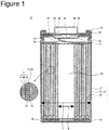
- FIG. 1 is a longitudinal sectional view of a non-aqueous electrolyte secondary battery 10 which is an example of an embodiment, and shows a section including a direction along the winding axis of an electrode assembly 14.
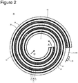
- FIG. 2 is a transverse sectional view in a plane perpendicular to the winding axis of the electrode assembly 14 constituting the non-aqueous electrolyte secondary battery 10 which is an example of an embodiment, and schematically shows the disposition of a positive electrode 11, a negative electrode 12 and a separator 13 constituting the electrode assembly 14.
- non-aqueous electrolyte secondary battery 10 illustrated as an embodiment is a cylindrical battery comprising a cylindrical case made of metal
- the non-aqueous electrolyte secondary battery of the present disclosure is not limited to this.
- the non-aqueous electrolyte secondary battery of the present disclosure may be, for example, a square battery comprising a square-shaped case made of metal, a laminated battery comprising an armor body comprising an aluminum laminate sheet, or the like.
- the non-aqueous electrolyte secondary battery 10 comprises the electrode assembly 14 having a winding structure and a non-aqueous electrolyte (not shown).
- the electrode assembly 14 comprises the positive electrode 11, the negative electrode 12 and the separator 13, and is formed by winding the positive electrode 11 and the negative electrode 12 through a separator 13 spirally.
- the non-aqueous electrolyte secondary battery 10 is a lithium secondary battery in which lithium metal deposits on the negative electrode 12 at the time of charge, and the lithium metal dissolves in the non-aqueous electrolyte at the time of discharge.
- All of the positive electrode 11, the negative electrode 12 and the separator 13 constituting the electrode assembly 14 are formed in the shapes of belts, wound spirally, and layered by turns in the diameter direction of the electrode assembly 14 thereby.
- the longitudinal direction of each electrode is the winding direction
- the cross direction of each electrode is the direction of the axis.
- the space (hollow part 50) including the axial center of the winding axis and extending along the direction of the axis is formed in the electrode assembly 14.
- the hollow part 50 will be described in detail hereinafter.
- a positive electrode lead 19 electrically connecting the positive electrode 11 and a positive electrode terminal is connected, for example, with the center in the longitudinal direction of the positive electrode 11, and extends from one end of the electrode assembly 14.
- a negative electrode lead 20 electrically connecting the negative electrode 12 and a negative electrode terminal is connected, for example, with an end in the longitudinal direction of the negative electrode 12, and extends from the other end of the electrode assembly 14.
- the negative electrode lead 20 connects with an end located outside in the diameter direction of the negative electrode 12, the negative electrode 12 lengthens in the winding direction at the time of the occurrence of stress in the negative electrode 12, and the range to which stress can be released is preferably widened.
- the battery case made of metal and housing the electrode assembly 14 and the non-aqueous electrolyte is constituted by a case body 15 and a sealing assembly 16. Insulating plates 17 and 18 are provided above and below the electrode assembly 14, respectively.
- the positive electrode lead 19 extends to the sealing assembly 16 side through a through hole of the insulating plate 17, and is welded to the lower surface of a filter 22 which is a bottom plate of the sealing assembly 16.
- the cap 26 of the sealing assembly 16 electrically connected with the filter 22 functions as the positive electrode terminal.
- the negative electrode lead 20 extends to the bottom side of the case body 15, and is welded to the inside of the bottom of the case body 15.
- the case body 15 functions as the negative electrode terminal.
- the case body 15 is a bottomed cylindrical container made of metal.
- a gasket 27 is provided between the case body 15 and the sealing assembly 16, and the sealability in the battery case is secured.
- the case body 15 has a projecting portion 21 which is formed, for example, by pressing a side portion from outside and supports the sealing assembly 16.
- the projecting portion 21 is preferably formed in a ring shape along the circumferential direction of the case body 15, and supports the sealing assembly 16 on its upper surface.
- the sealing assembly 16 has a structure in which the filter 22, a lower vent member 23, an insulating member 24, an upper vent member 25 and the cap 26 are layered sequentially from the electrode assembly 14 side.
- Members constituting the sealing assembly 16 have, for example, disk shapes or ring shapes, and the members except the insulating member 24 are electrically connected with each other.
- the lower vent member 23 and the upper vent member 25 are connected with each other at the respective centers, and the insulating member 24 is between the respective peripheries.
- the lower vent member 23 is provided with an air holes, and the upper vent member 25 therefore swells to the cap 26 side, and is separated from the lower vent member 23. The electrical connection between both is cut off thereby.
- the upper vent member 25 ruptures and gas is discharged from an opening of the cap 26.
- the hollow part 50 which is a space including the axial center of the winding axis and extending along the direction of the axis is formed in the electrode assembly 14 according to the present disclosure.
- a negative electrode 12 not including a negative electrode mixture layer on the negative electrode current collector 40 is used in the lithium secondary battery, lithium metal dissolving in the electrolytic solution deposits on the surface of the negative electrode 12 at the time of charge.
- the hollow part 50 formed in the non-aqueous electrolyte secondary battery 10 of the present disclosure enables suppressing the rupture of the electrodes resulting from this lithium depositing on the negative electrode 12. It is considered that the principle is as follows.
- Electrodes Such deposition of lithium occurs ununiformly on the surface of the negative electrode 12. Therefore, a local distortion occurs in the electrode assembly 14, and stress occurs especially in the positive electrode 11 and the negative electrode 12 (when the positive electrode 11 and the negative electrode 12 are not distinguished, both are generically named “electrodes” herein) including current collectors made of metal. As charge proceeds further, the amount of lithium deposited increases (swelling), stress which occurs in the electrodes is increased. Since the electrodes and the separator are densely layered in the case body for an increase in capacity in a battery not including a hollow part 50, stress which occurs in the electrodes is not released. Therefore, fatigue accumulates in the electrodes by stress which occurs every time a charge and discharge cycle is repeated, and the electrodes rupture after all.
- the hollow part 50 which can allow the electrodes and the separator 13 to move is secured in the center of the electrode assembly 14.
- the stress which occurs can therefore be released by lengthening the electrodes spirally along the winding direction (the direction of an arrow A in FIG. 2 ) or moving the electrodes and the like slightly inside in the layering direction (the direction of an arrow B in FIG. 2 ) in the case of the electrodes and the like near the axis center. Therefore, it is considered that even though a charge and discharge cycle is repeated, fatigue by the occurrence of stress is not accumulated in the electrodes, and the rupture of the electrodes resulting from the deposition of lithium can be suppressed consequently.
- the formation of the hollow part 50 in the lithium secondary battery is disadvantageous with respect to the improvement in the capacity of the battery.
- a space in which the negative electrode mixture layer is not provided can be used for expanding the areas of the positive electrode 11 and the negative electrode 12 per battery and increasing the content of a lithium-containing transition metal oxide which is a positive electrode active material per battery as compared with a conventional lithium secondary battery in which negative electrode mixture layers are provided on both sides of the negative electrode current collector. Therefore, the positive electrode capacity per battery increases beyond a capacity decrease by forming the hollow part, and the increase in capacity of the battery can be achieved.
- the hollow part 50 when the non-aqueous electrolyte secondary battery 10 is in a discharge state, the hollow part 50 is formed so that the positive electrode capacity of the positive electrode 11, ⁇ (mAh), and the volume of the hollow part 50, X (mm 3 ), satisfy 0.5 ⁇ X/ ⁇ ⁇ 4.0.
- the positive electrode capacity of the positive electrode 11, ⁇ at the time of the discharge of the non-aqueous electrolyte secondary battery 10 is calculated by the product of the theoretical capacity of lithium metal (3860 mAh/g) by the total mass of lithium included in the positive electrode 11, more specifically the positive electrode mixture layer 31.
- the total mass of lithium included in the positive electrode mixture layer 31 may be calculated, for example, based on the composition and the thickness of the positive electrode mixture layer 31, and the total area of the wound positive electrode mixture layer 31.
- the volume of the hollow part 50 X is the volume of a space including the winding axis center of the electrode assembly 14, extending in the direction of the axis, and surrounded by an end face in the direction of the axis of the electrode assembly 14 and the innermost layer in the electrode assembly 14 (the separator 13 in FIG. 1 and FIG. 2 ).
- the ratio of the volume of the hollow part 50, X, to the positive electrode capacity of the positive electrode 11, ⁇ expresses the relationship between the amount of lithium metal deposited on the negative electrode 12 at the time of charge and the space occupying the hollow part 50.
- the ratio X/ ⁇ is too low, a space to which the positive electrode 11 and the negative electrode 12 move to release stress which occurs by the deposition of lithium metal cannot be secured, and the effect of preventing electrode rupture is not obtained fully.
- the ratio X/ ⁇ is too high, the lithium content per battery decreases, and the effect of capacity improvement over a conventional battery manufactured using a negative electrode including a negative electrode mixture layer is lost.
- the positive electrode capacity of the positive electrode 11, ⁇ , and the volume of the hollow part 50, X preferably satisfy 0.5 ⁇ X/ ⁇ ⁇ 4.0, and more preferably satisfy 0.5 ⁇ X/ ⁇ ⁇ 1.9 from the above-mentioned viewpoints.
- the hollow part 50 is formed so that the inner diameter of the case body 15 Y and the inner diameter of the electrode assembly 14 Z satisfy 0.4 ⁇ Z/Y ⁇ 0.8.
- Both the inner diameter of the case body 15 Y and the inner diameter of the electrode assembly 14 Z are average values in a cross-section perpendicular to the winding axis and average values along the direction of the winding axis at the same time.
- the inner diameter of the case body 15 Y and the inner diameter of the electrode assembly 14 Z in a discharge state preferably satisfy 0.40 ⁇ Z/Y ⁇ 0.80, and more preferably satisfy 0.40 ⁇ Z/Y ⁇ 0.60 from the above-mentioned viewpoints.
- the volume of the hollow part 50 X, the inner diameter of the case body 15 Y, and the inner diameter of the electrode assembly 14 Z in the non-aqueous electrolyte secondary battery 10 may be measured, for example, using an X-ray CT apparatus (for example, "Microfocus X-Ray Fluoroscopy System SMX-2000" manufactured by SHIMADZU CORPORATION).
- the positive electrode capacity of the positive electrode 11, ⁇ is calculated as the product of the total mass of lithium included in the positive electrode mixture layer 31 by the theoretical capacity of lithium metal (3860 mAh/g) as mentioned above.
- the total mass of lithium included in the positive electrode mixture layer 31 is calculated, for example, based on the composition, the thickness and the total area of the positive electrode mixture layer 31.
- the thickness and the total area of the positive electrode mixture layer 31 may be measured using the above-mentioned X-ray CT apparatus.
- the composition of the lithium-containing transition metal oxide included in the positive electrode mixture layer 31 is subjected to qualitative and quantitative analyses using a well-known analysis apparatus such as an ICP emission spectrophotometer (for example, "CIROS-120" manufactured by Spectro Corporation).
- ICP emission spectrophotometer for example, "CIROS-120" manufactured by Spectro Corporation.
- the volume of the hollow part 50 X, the inner diameter of the case body 15 Y, and the inner diameter of the electrode assembly 14 Z are values measured at the time of the initial stage of cycles, and are measured, for example, using a battery in 10 cycles or less.
- the molar ratio of the total amount of lithium which the positive electrode 11 and the negative electrode 12 have to the amount of the transition metal included in the positive electrode 11 is 1.1 or less.
- the total amount (the total content) of lithium which the positive electrode 11 and the negative electrode 12 have is the total amount of lithium constituting the lithium-containing transition metal oxide included in the positive electrode mixture layer 31 of the positive electrode 11 as the positive electrode active material and lithium when the negative electrode current collector 40 of the negative electrode 12 has the lithium metal in the non-aqueous electrolyte secondary battery 10.
- the positive electrode 11 comprises the positive electrode current collector 30 and the positive electrode mixture layer 31 formed on the current collector. Foil of a metal such as aluminum which is stable in the potential range of the positive electrode 11, a film wherein the metal is disposed on the outer layer, or the like can be used for the positive electrode current collector 30.
- the positive electrode mixture layer 31 comprises the positive electrode active material, a conductive agent and a binding agent. Positive electrode mixture layers 31 are generally formed on both surfaces of the positive electrode current collector 30.
- the positive electrode 11 can be manufactured, for example by applying positive electrode mixture slurry including the positive electrode active material, the conductive agent, the binding agent and the like to the positive electrode current collector 30, drying the coating films, and then rolling the coating films to form positive electrode mixture layers 31 on both surfaces of the current collector,
- the positive electrode active material included in the positive electrode mixture layer 31 comprises a lithium-containing transition metal oxide.
- a metallic element other than lithium constituting a lithium-containing transition metal oxide is, for example, at least one selected from magnesium (Mg), aluminum (Al), calcium (Ca), scandium (Sc), titanium (Ti), vanadium (V), chromium (Cr), manganese (Mn), iron (Fe), cobalt (Co), nickel (Ni), copper (Cu), zinc (Zn), gallium (Ga), germanium (Ge), yttrium (Y), zirconium (Zr), tin (Sn), antimony (Sb), tungsten (W), lead (Pb) and bismuth (Bi).
- the lithium-containing transition metal oxide included in the positive electrode mixture layer 31 preferably includes at least one selected from Co, Ni, Mn, and Al as the transition metals.
- the molar ratio of lithium to the transition metal constituting the lithium-containing transition metal is 1.1:1 or less.
- Examples of the conductive agent constituting the positive electrode mixture layer 31 include carbon materials such as carbon black (CB), acetylene black (AB), ketjen black and graphite.
- Examples of the binding agent constituting the positive electrode mixture layer 31 include fluorine-containing resins such as polytetrafluoroethylene (PTFE) and polyvinylidene fluoride (PVDF); polyacrylonitrile (PAN); polyimide-based resins; acrylic-based resins and polyolefin-based resin. These may be used alone or in combination of two or more.
- the lithium-containing transition metal oxide included in the positive electrode mixture layer 31 preferably has a crystal structure belonging to the space group R-3m.
- the crystal structure belonging to the space group R-3m is a structure formed by layering lithium-oxygen octahedral layers and transition metal-oxygen octahedral layers, and is a crystal structure which, for example, lithium nickelate (LiNiO 2 ) and lithium cobaltate (LiCoO 2 ) have. It is because when the positive electrode active material has a crystal structure belonging to the space group R-3m, a high charge and discharge capacity is obtained in the secondary battery.
- the positive electrode active material has a crystal structure belonging to the space group R-3m, for example, by performing analysis based on a powder X-ray diffractometry as to the positive electrode active material and obtaining an X-ray diffraction pattern.
- the negative electrode 12 is an electrode on which lithium metal is deposited at the time of charge, and has the negative electrode current collector 40.
- Lithium metal which deposits on the negative electrode 12 by charge is derived from lithium ions in the non-aqueous electrolyte, and the depositing lithium metal dissolves in the electrolytic solution by discharge.
- the negative electrode current collector 40 comprises metallic foil such as copper, nickel, iron and stainless alloy (SUS), and copper foil with high conductivity is particularly preferable.
- the copper foil is metallic foil including copper as the main component, and may comprise only copper substantially.
- the thickness of the copper foil is preferably 5 mm or more and 20 mm or less.
- the negative electrode 12 comprises only copper foil having a thickness of 5 mm or more and 20 mm or less, for example, before the charge and discharge of the battery. Lithium metal deposits on both surfaces of the copper foil by charge to form lithium metal layers.
- the negative electrode current collector 40 may contain a lithium metal layer.
- the lithium metal layer may be lithium metal foil, or may be an article wherein a lithium metal layer is formed on the surface by vapor deposition or the like (in this case, the lithium functions as an active material).
- the negative electrode current collector 40 does not preferably have a negative electrode active material in the initial state.
- the negative electrode 12 preferably comprises only the negative electrode current collector 40 in the initial state.
- the volume energy density of the battery can be increased thereby.
- a current collector or the like including lithium metal foil or a lithium metal layer is used as the negative electrode current collector 40, the volume energy density of the battery decreases by the thickness of the lithium layer.
- the negative electrode current collector 40 may have a layer including a solid electrolyte, organic matter and inorganic matter (protective layer) on the surface.
- the protective layer has the effect of uniforming an electrode surface reaction, lithium metal uniformly deposits on the negative electrode, and the swelling of the negative electrode 12 can be suppressed.
- a solid electrolyte include sulfide-based solid electrolytes, phosphate-based solid electrolytes, perovskite-based solid electrolytes and garnet-based solid electrolytes.
- the sulfide-based solid electrolytes contain a sulfur component and have lithium ion conductivity
- the sulfide-based solid electrolytes are not particularly limited.
- Specific examples of raw materials of the sulfide-based solid electrolytes include a raw material including Li, S and the third component A.
- Examples of the third component A include at least one selected from the group consisting of P, Ge, B, Si, I, Al, Ga and As.
- Specific examples of the sulfide-based solid electrolytes include Li 2 S-P 2 S 5 , 70Li 2 S-30P 2 S 5 , 80Li 2 S-20P 2 S 5 , Li 2 S-SiS 2 and LiGe 0.25 P 0.75 S 4 .
- the phosphate-based solid electrolytes contain a phosphate component and have lithium ion conductivity
- the phosphate-based solid electrolytes are not particularly limited.
- the phosphate-based solid electrolytes include Li 1+X Al X Ti 2-X (PO 4 ) 3 (0 ⁇ X ⁇ 2, particularly preferably 0 ⁇ X ⁇ 1), such as Li 1.5 Al 0.5 Ti 1.5 (PO 4 ) 3 ; and Li 1+X Al X Ge 2-X (PO 4 ) 3 (0 ⁇ X ⁇ 2, particularly preferably 0 ⁇ X ⁇ 1).
- lithium conductive substances such as polyethylene oxide and polymethyl methacrylate are preferable.
- ceramic materials such as SiO 2 , Al 2 O 3 and MgO are preferable.
- a porous sheet including ion permeability and insulation properties is used for the separator 13.
- the porous sheet include fine porous thin films, woven fabrics and nonwoven fabrics.
- olefin-based resins such as polyethylene, polypropylene and a copolymer including at least either of ethylene and propylene; cellulose; and the like are preferable.
- the separator 13 may be a layered body including a cellulose fiber layer and a thermoplastic resin fiber layer such as an olefin-based resin.
- the separator 13 may be a multilayer separator including a polyethylene layer and a polypropylene layer, and the separator 13 wherein an aramid-based resin or the like were applied to the surface of the separator 13 may be used.
- a heat-resistant layer including a filler of an inorganic compound may be formed on the interface between the separator 13 and at least either of the positive electrode 11 and the negative electrode 12.
- the non-aqueous electrolyte includes a non-aqueous solvent and an electrolyte salt dissolving in the non-aqueous solvent.
- a non-aqueous solvent for example, esters; ethers; nitriles such as acetonitrile; amides such as dimethylformamide; mixed solvents of two or more of these; and the like can be used for the non-aqueous solvent.
- the non-aqueous solvent may contain halogen substitution products in which at least some of the hydrogen atoms of these solvents are replaced with halogen atoms such as fluorine atoms.
- the non-aqueous electrolyte is not limited to a liquid electrolyte (non-aqueous electrolytic solution), and may be a solid electrolyte using a gel polymer or the like.
- esters examples include cyclic carbonic esters such as ethylene carbonate (EC), propylene carbonate (PC), butylene carbonate and fluoroethylene carbonate (FEC); chain-like carbonic esters such as dimethyl carbonate (DMC), ethyl methyl carbonate (EMC), diethyl carbonate (DEC), methyl propyl carbonate, ethyl propyl carbonate and methyl isopropyl carbonate; cyclic carboxylate esters such as ⁇ - butyrolactone and ⁇ -valerolactone; and chain-like carboxylate esters such as methyl acetate, ethyl acetate, propyl acetate, methyl propionate (MP), ethyl propionate, ⁇ -butyrolactone and fluoromethyl propionate (FMP).
- cyclic carbonic esters such as ethylene carbonate (EC), propylene carbonate (PC), butylene carbonate and fluoroethylene carbonate (FEC);
- ethers examples include cyclic ethers such as 1,3-dioxolane, 4-methyl-1,3-dioxolane, tetrahydrofuran, 2-methyltetrahydrofuran, propylene oxide, 1,2-butylene oxide, 1,3-dioxane, 1,4-dioxane, 1,3,5-trioxane, furan, 2-methylfuran, 1,8-cineol and crown ethers; and chain-like ethers such as 1,2-dimethoxyethane, diethyl ether, dipropyl ether, diisopropyl ether, dibutyl ether, dihexyl ether, ethyl vinyl ether, butyl vinyl ether, methyl phenyl ether, ethyl phenyl ether, butyl phenyl ether, pentyl phenyl ether, methoxytoluene, benzyl ethoxyethane, die
- Examples of the electrolyte salt included in the non-aqueous electrolyte include LiBF 4 , LiClO 4 , LiPF 6 , LiAsF 6 , LiSbF 6 , LiAlCl 4 , LiSCN, LiCF 3 SO 3 , LiCF 3 CO 2 , and imide salts such as LiN(SO 2 CF 3 ) 2 , LiN(C l F 2l+1 SO 2 )(C m F 2m+1 SO 2 ) ⁇ 1 and m are integers of 1 or more ⁇ .
- LiPF 6 is preferably used particularly.
- the non-aqueous electrolyte preferably includes an additive decomposed on the negative electrode 12.
- the non-aqueous electrolyte includes at least one selected, for example, from vinylene carbonate (VC), fluoroethylene carbonate (FEC) and vinyl ethyl carbonate (VEC).
- VC vinylene carbonate
- FEC fluoroethylene carbonate
- VEC vinyl ethyl carbonate
- the swelling of a negative electrode is further suppressed by adding VC and the like, and the cycle characteristics become better.
- NMP N-methyl-2-pyrrolidone
- the positive electrode mixture slurry was applied to both surfaces of a positive electrode current collector comprising aluminum foil, and the coating films were dried.
- the coating films were rolled using a roller, and the electrode was then cut to a predetermined electrode size to manufacture a positive electrode in which the positive electrode mixture layers were formed on both sides of the positive electrode current collector sequentially.
- the molar ratio of lithium to the total of the transition metals in the lithium-containing transition metal oxide used as the positive electrode active material was 1.0.
- Electrolytic copper foil (10 ⁇ m in thickness) was cut to a predetermined electrode size to form a negative electrode (negative electrode current collector).
- the copper foil was not coated with a negative electrode mixture.
- Ethylene carbonate (EC) and dimethyl carbonate (DMC) were mixed at a volume ratio of 3:7.
- LiPF 6 was dissolved in the mixed solvent at a concentration of 1.0 M (mol/L)
- LiBF 2 (C 2 O 4 ) was dissolved in the mixed solvent at a concentration of 0.1 M (mol/L) to prepare a non-aqueous electrolytic Solution.
- the above-mentioned positive electrode to which a tab made of aluminum was attached and the above-mentioned negative electrode to which a tab made of nickel was attached were wound spirally through a separator made of polyethylene to manufacture an electrode assembly.
- a space including the axis center of the winding axis and extending in the direction of the winding axis was formed in the electrode assembly of Example 1.
- the above-mentioned non-aqueous electrolytic solution was injected, and the opening of the armor body was then sealed to manufacture a cylindrical battery T1 having a hollow part with a volume of 5000 mm 3 and a positive electrode capacity ⁇ of 7500 mAh.
- the molar ratio of the total amount of lithium included in the battery T1 to the amount of the transition metals included in the positive electrode was 1.0.
- a cylindrical battery T2 having a hollow part with a volume of 7250 mm 3 and a positive electrode capacity ⁇ of 3900 mAh was manufactured in the same way as in Example 1 except that the volume of the hollow part was changed using a belt-shaped positive electrode, a belt-shaped negative electrode and a belt-shaped separator which were different in length in the longitudinal direction (the winding direction) in the manufacturing of the battery.
- Cylindrical batteries T3 and T4 having hollow parts were manufactured in the same way as in Example 1 except that the volumes of the hollow parts were changed using belt-shaped positive electrodes, belt-shaped negative electrodes and belt-shaped separators which are different in length in the longitudinal direction (the winding direction) in the manufacturing of the batteries in the same way.
- the volume of the hollow part of the battery T3 was 800 mm 3
- the positive electrode capacity ⁇ was 7500 mAh.
- the volume of the hollow part of the battery T4 was 15000 mm 3
- the positive electrode capacity ⁇ was 3400 mAh.
- a battery for reference was manufactured for comparing discharge capacities.
- the battery for reference comprises a negative electrode including negative electrode mixture layers on both sides of copper foil.
- Negative electrode mixture slurry containing graphite as an negative electrode active material and a binding agent (styrene-butadiene rubber) at a mass ratio of 97.5:2.5 was applied to both sides of the copper foil which is an negative electrode current collector, the coating films were dried, and the coating films were then rolled with a rolling roller to prepare the negative electrode.
- the battery T5 for reference having a positive electrode capacity ⁇ of 3400 mAh was manufactured in the same way as in Example 1 except that the negative electrode including the negative electrode mixture layers obtained by the above-mentioned method was used as an negative electrode, and the lengths of a belt-shaped positive electrode, belt-shaped negative electrode and belt-shaped separator were adjusted so that almost no space was formed at the center.
- a charge and discharge cycle test was performed as to each of the batteries of the Examples and the Comparative Examples. Under a battery temperature condition of 25°C, the battery was subjected to constant current charge at a current of 0.1 It until the voltage value was 4.3 V, and the battery was then subjected to constant voltage charge at a constant voltage of 4.3V until the current value was 0.01 It using each battery. Then, the battery was subjected to constant current discharge at a current of 0.1 It until the voltage value was 2.5V, and the discharge capacity when the battery was subjected to this constant current discharge was defined as the initial discharge capacity of each battery.
- each battery As to each battery, a charge and discharge cycle comprising constant current charge to 4.3 V at a current of 0.1 It, an idle period of 15 minutes, constant current discharge to 2.5 V at a current of 0.1 It, and an idle period of 15 minutes was next repeated 5 times under a temperature condition of 60°C. Then, each battery was taken out when the voltage value was 3.5 V or more and 3.6 V or less in the discharge state.
- the volume of the hollow part X, the inner diameter of the case, Y, and the inner diameter of the electrode assembly, Z were measured, and it was observed whether the electrodes ruptured using an X-ray CT apparatus (for example, "Microfocus X-Ray Fluoroscopy System SMX-2000" manufactured by SHIMADZU CORPORATION).
- X-ray CT apparatus for example, "Microfocus X-Ray Fluoroscopy System SMX-2000” manufactured by SHIMADZU CORPORATION.
- “Volume of hollow part X (mm 3 )/positive electrode capacity ⁇ (mAh)” and "outer diameter of hollow part Z (mm)/inner diameter of case Y (mm)” were calculated from the obtained measurement results.
- the positive electrode capacity ⁇ is a theoretical value calculated as to each battery based on the theoretical capacity of Li metal (3860 mAh/g), the composition and the layer thickness of the positive electrode mixture layer, and the area in which the positive electrode mixture layer was formed. Table 1 shows the calculation results.
- the discharge capacity of each of the batteries of the Examples and the Comparative Examples was evaluated by comparing with the discharge capacity of the battery for reference.
- the battery for reference is a conventional non-aqueous electrolyte secondary battery wherein the battery comprises a negative electrode including negative electrode mixture layers on both surfaces, and almost no space is formed at the center of an electrode assembly.
- a battery having the discharge capacity of the battery for reference or less was rated as "poor", and a battery having more discharge capacity than the battery for reference was rated as "good” based on the theoretical capacity of Li metal of each battery (3860 mAh/g), the composition and the layer thickness of a positive electrode mixture layer, and the value of the discharge capacity calculated based on an area in which positive electrode mixture layers were formed.
- the stress could be released by providing the space (hollow part 50) at the center of the electrode assembly 14 comprising the positive electrode 11, the negative electrode 12 and the separator 13 in the lithium deposition lithium secondary battery in which the negative electrode mixture layer was not provided on the negative electrode current collector 40, and the rupture of the electrodes was consequently suppressed. It is considered that although the electrode assembly 14 did not exist in the hollow part 50, the negative electrode 12 did not have the negative electrode mixture layer in the present embodiment, and the energy density per battery therefore improved and the increase in capacity of the battery was achieved.
Landscapes
- Chemical & Material Sciences (AREA)
- Engineering & Computer Science (AREA)
- Chemical Kinetics & Catalysis (AREA)
- Electrochemistry (AREA)
- General Chemical & Material Sciences (AREA)
- Materials Engineering (AREA)
- Manufacturing & Machinery (AREA)
- Inorganic Chemistry (AREA)
- Secondary Cells (AREA)
- Sealing Battery Cases Or Jackets (AREA)
- Cell Electrode Carriers And Collectors (AREA)
- Battery Electrode And Active Subsutance (AREA)
Abstract
Description
- The present disclosure relates to a non-aqueous electrolyte secondary battery, and more specifically to a lithium secondary battery.
- A further increase in capacity of non-aqueous electrolyte secondary batteries has been required also in the field of equipment for vehicles, the field of the accumulation of electricity, and the like in addition to the ICT field of apparatuses such as personal computers and smart phones. As non-aqueous electrolyte secondary batteries with high capacity, lithium ion batteries have been used exclusively. Although a configuration in which, for example, a lithium-containing transition metal oxide is used for a positive electrode, and a negative electrode active material comprising graphite, a silicon compound and the like is used for an negative electrode is known as a lithium ion battery, this configuration is reaching the limit with respect to an increase in capacity.
- Patent Literature 1 discloses a lithium battery in which a part of a positive electrode comprises a lithium transition metal oxide having an inverse spinel structure, and a negative electrode is selected from the group consisting of lithium metal, a lithium alloy and a lithium intercalation compound.
- Patent Literature 2 discloses a rechargeable battery in which a part of a positive electrode comprises a specific lithium manganese oxide intercalation compound, a negative electrode comprises a lithium manganese oxide intercalation compound, and an electrolyte comprises a lithium salt dissolved in a non-aqueous solvent.
- PATENT LITERATURE 1: Japanese Unexamined Patent Application Publication No.
Hei7-243957 - In a battery system using a lithium-containing transition metal oxide for a positive electrode and also using lithium metal for a negative electrode like a technique disclosed in Patent Literature 1, the amount of lithium metal in the system increased, the amount of lithium metal based on the amount of the transition metal in the system was however surplus, and it could not, therefore, be said that the capacity improvement effect was enough. There is a lithium secondary battery in which lithium metal is deposited on a negative electrode at the time of charge, and the lithium metal is dissolved in a non-aqueous electrolyte at the time of discharge as a non-aqueous electrolyte secondary battery which is promising with respect to an increase in capacity. However, there was a problem that in such a lithium secondary battery, stress occurred in the electrode by the expansion of the negative electrode due to the deposition of lithium metal and ununiform deposition of lithium metal on the surface of the negative electrode, and an electrode ruptured after all by repeated occurrence of stress in the electrode in every charge and discharge cycle.
- Then, a non-aqueous electrolyte secondary battery which enables suppressing the rupture of an electrode which can occur when a charge and discharge cycle is repeated while achieving the increase in capacity of the battery has been required.
- A non-aqueous electrolyte secondary battery which is one aspect of the present disclosure comprises: an electrode assembly including a positive electrode including a positive electrode active material comprising a lithium-containing transition metal oxide, a negative electrode, including a negative electrode current collector, wherein lithium metal deposits on the negative electrode current collector at the time of charge, and a separator disposed between the positive electrode and the negative electrode; and a non-aqueous electrolyte, and is characterized in that a molar ratio of a total amount of lithium which the positive electrode and the negative electrode have to an amount of the transition metal included in the positive electrode is 1.1 or less, and a positive electrode capacity of the positive electrode, α (mAh), and a volume of a space formed at a center of the electrode assembly, X (mm3), satisfy 0.5 ≤ X/α ≤ 4.0 in a discharge state.
- A non-aqueous electrolyte secondary battery which is another aspect of the disclosure comprises: an electrode assembly including a positive electrode including a positive electrode active material comprising a lithium-containing transition metal oxide, a negative electrode, including a negative electrode current collector, wherein lithium metal deposits on the negative electrode current collector at the time of charge, and a separator disposed between the positive electrode and the negative electrode; a non-aqueous electrolyte; and a case housing the electrode assembly and the non-aqueous electrolyte, and is characterized in that a molar ratio of a total amount of lithium which the positive electrode and the negative electrode have to an amount of the transition metal included in the positive electrode is 1.1 or less, and an inner diameter of the case, Y, and an inner diameter of the electrode assembly, Z, satisfy 0.4 ≤ Z/Y ≤ 0.8 in a discharge state.
- According to the present disclosure, a non-aqueous electrolyte secondary battery which enables suppressing the rupture of an electrode which can occur when a charge and discharge cycle is repeated while achieving the increase in capacity of the battery can be provided.
-
-
FIG. 1 is a longitudinal sectional view showing a non-aqueous electrolyte secondary battery which is an example of an embodiment. -
FIG. 2 is a partially transverse sectional view of an electrode assembly constituting a non-aqueous electrolyte secondary battery which is an example of an embodiment. - As mentioned above, the increase in capacity of a non-aqueous electrolyte secondary battery (lithium secondary battery) in which lithium metal deposits on an negative electrode at the time of charge, and the lithium metal dissolves in a non-aqueous electrolyte at the time of discharge can be expected, and the battery however has a problem that the electrode ruptures due to stress which occurs with the swelling due to lithium metal which deposits on the negative electrode. The present inventors have examined earnestly to solve such a problem and consequently found that even though lithium metal deposits on the negative electrode at the time of charge, and stress occurs in the electrodes (the positive electrode and the negative electrode) by the depositing lithium metal; a space is formed at the axial center of the winding axis of the electrode assembly comprising the positive electrode, the negative electrode and the separator beforehand, and the rupture of the electrodes can be suppressed by releasing the stress to the space thereby.
- An example of an embodiment of a non-aqueous electrolyte secondary battery according to the present disclosure will be described in detail hereinafter.
FIG. 1 is a longitudinal sectional view of a non-aqueous electrolytesecondary battery 10 which is an example of an embodiment, and shows a section including a direction along the winding axis of anelectrode assembly 14.FIG. 2 is a transverse sectional view in a plane perpendicular to the winding axis of theelectrode assembly 14 constituting the non-aqueous electrolytesecondary battery 10 which is an example of an embodiment, and schematically shows the disposition of apositive electrode 11, anegative electrode 12 and aseparator 13 constituting theelectrode assembly 14. - Although the non-aqueous electrolyte
secondary battery 10 illustrated as an embodiment is a cylindrical battery comprising a cylindrical case made of metal, the non-aqueous electrolyte secondary battery of the present disclosure is not limited to this. The non-aqueous electrolyte secondary battery of the present disclosure may be, for example, a square battery comprising a square-shaped case made of metal, a laminated battery comprising an armor body comprising an aluminum laminate sheet, or the like. - As illustrated in
FIG. 1 , the non-aqueous electrolytesecondary battery 10 comprises theelectrode assembly 14 having a winding structure and a non-aqueous electrolyte (not shown). As shown inFIG. 1 andFIG. 2 , theelectrode assembly 14 comprises thepositive electrode 11, thenegative electrode 12 and theseparator 13, and is formed by winding thepositive electrode 11 and thenegative electrode 12 through aseparator 13 spirally. The non-aqueous electrolytesecondary battery 10 is a lithium secondary battery in which lithium metal deposits on thenegative electrode 12 at the time of charge, and the lithium metal dissolves in the non-aqueous electrolyte at the time of discharge. - All of the
positive electrode 11, thenegative electrode 12 and theseparator 13 constituting theelectrode assembly 14 are formed in the shapes of belts, wound spirally, and layered by turns in the diameter direction of theelectrode assembly 14 thereby. In theelectrode assembly 14, the longitudinal direction of each electrode is the winding direction, and the cross direction of each electrode is the direction of the axis. The space (hollow part 50) including the axial center of the winding axis and extending along the direction of the axis is formed in theelectrode assembly 14. Thehollow part 50 will be described in detail hereinafter. - A positive electrode lead 19 electrically connecting the
positive electrode 11 and a positive electrode terminal is connected, for example, with the center in the longitudinal direction of thepositive electrode 11, and extends from one end of theelectrode assembly 14. A negative electrode lead 20 electrically connecting thenegative electrode 12 and a negative electrode terminal is connected, for example, with an end in the longitudinal direction of thenegative electrode 12, and extends from the other end of theelectrode assembly 14. In theelectrode assembly 14, when thenegative electrode lead 20 connects with an end located outside in the diameter direction of thenegative electrode 12, thenegative electrode 12 lengthens in the winding direction at the time of the occurrence of stress in thenegative electrode 12, and the range to which stress can be released is preferably widened. - In the example shown in
FIG. 1 , the battery case made of metal and housing theelectrode assembly 14 and the non-aqueous electrolyte is constituted by acase body 15 and asealing assembly 16.Insulating plates electrode assembly 14, respectively. Thepositive electrode lead 19 extends to thesealing assembly 16 side through a through hole of theinsulating plate 17, and is welded to the lower surface of afilter 22 which is a bottom plate of thesealing assembly 16. In the non-aqueous electrolytesecondary battery 10, thecap 26 of thesealing assembly 16 electrically connected with thefilter 22 functions as the positive electrode terminal. Meanwhile, thenegative electrode lead 20 extends to the bottom side of thecase body 15, and is welded to the inside of the bottom of thecase body 15. In the non-aqueous electrolytesecondary battery 10, thecase body 15 functions as the negative electrode terminal. - The
case body 15 is a bottomed cylindrical container made of metal. Agasket 27 is provided between thecase body 15 and thesealing assembly 16, and the sealability in the battery case is secured. Thecase body 15 has a projecting portion 21 which is formed, for example, by pressing a side portion from outside and supports thesealing assembly 16. The projecting portion 21 is preferably formed in a ring shape along the circumferential direction of thecase body 15, and supports thesealing assembly 16 on its upper surface. - The
sealing assembly 16 has a structure in which thefilter 22, alower vent member 23, aninsulating member 24, anupper vent member 25 and thecap 26 are layered sequentially from theelectrode assembly 14 side. Members constituting thesealing assembly 16 have, for example, disk shapes or ring shapes, and the members except the insulatingmember 24 are electrically connected with each other. Thelower vent member 23 and theupper vent member 25 are connected with each other at the respective centers, and theinsulating member 24 is between the respective peripheries. When the internal pressure of the battery increases by abnormal heat generation, thelower vent member 23 is provided with an air holes, and theupper vent member 25 therefore swells to thecap 26 side, and is separated from thelower vent member 23. The electrical connection between both is cut off thereby. When the internal pressure further increases, theupper vent member 25 ruptures and gas is discharged from an opening of thecap 26. - The
hollow part 50 which is a space including the axial center of the winding axis and extending along the direction of the axis is formed in theelectrode assembly 14 according to the present disclosure. When anegative electrode 12 not including a negative electrode mixture layer on the negativeelectrode current collector 40 is used in the lithium secondary battery, lithium metal dissolving in the electrolytic solution deposits on the surface of thenegative electrode 12 at the time of charge. Thehollow part 50 formed in the non-aqueous electrolytesecondary battery 10 of the present disclosure enables suppressing the rupture of the electrodes resulting from this lithium depositing on thenegative electrode 12. It is considered that the principle is as follows. - Such deposition of lithium occurs ununiformly on the surface of the
negative electrode 12. Therefore, a local distortion occurs in theelectrode assembly 14, and stress occurs especially in thepositive electrode 11 and the negative electrode 12 (when thepositive electrode 11 and thenegative electrode 12 are not distinguished, both are generically named "electrodes" herein) including current collectors made of metal. As charge proceeds further, the amount of lithium deposited increases (swelling), stress which occurs in the electrodes is increased. Since the electrodes and the separator are densely layered in the case body for an increase in capacity in a battery not including ahollow part 50, stress which occurs in the electrodes is not released. Therefore, fatigue accumulates in the electrodes by stress which occurs every time a charge and discharge cycle is repeated, and the electrodes rupture after all. - Meanwhile, in the non-aqueous electrolyte
secondary battery 10 of the present disclosure, thehollow part 50 which can allow the electrodes and theseparator 13 to move is secured in the center of theelectrode assembly 14. When stress occurs in the electrodes at the time of charge, the stress which occurs can therefore be released by lengthening the electrodes spirally along the winding direction (the direction of an arrow A inFIG. 2 ) or moving the electrodes and the like slightly inside in the layering direction (the direction of an arrow B inFIG. 2 ) in the case of the electrodes and the like near the axis center. Therefore, it is considered that even though a charge and discharge cycle is repeated, fatigue by the occurrence of stress is not accumulated in the electrodes, and the rupture of the electrodes resulting from the deposition of lithium can be suppressed consequently. - It can be said that the formation of the
hollow part 50 in the lithium secondary battery is disadvantageous with respect to the improvement in the capacity of the battery. However, in the non-aqueous electrolytesecondary battery 10 of the present disclosure, a space in which the negative electrode mixture layer is not provided can be used for expanding the areas of thepositive electrode 11 and thenegative electrode 12 per battery and increasing the content of a lithium-containing transition metal oxide which is a positive electrode active material per battery as compared with a conventional lithium secondary battery in which negative electrode mixture layers are provided on both sides of the negative electrode current collector. Therefore, the positive electrode capacity per battery increases beyond a capacity decrease by forming the hollow part, and the increase in capacity of the battery can be achieved. - According to one aspect of the present disclosure, when the non-aqueous electrolyte
secondary battery 10 is in a discharge state, thehollow part 50 is formed so that the positive electrode capacity of thepositive electrode 11, α (mAh), and the volume of thehollow part 50, X (mm3), satisfy 0.5 ≤ X/α ≤ 4.0. The positive electrode capacity of thepositive electrode 11, α at the time of the discharge of the non-aqueous electrolytesecondary battery 10 is calculated by the product of the theoretical capacity of lithium metal (3860 mAh/g) by the total mass of lithium included in thepositive electrode 11, more specifically the positiveelectrode mixture layer 31. The total mass of lithium included in the positiveelectrode mixture layer 31 may be calculated, for example, based on the composition and the thickness of the positiveelectrode mixture layer 31, and the total area of the wound positiveelectrode mixture layer 31. Meanwhile, the volume of the hollow part 50 X is the volume of a space including the winding axis center of theelectrode assembly 14, extending in the direction of the axis, and surrounded by an end face in the direction of the axis of theelectrode assembly 14 and the innermost layer in the electrode assembly 14 (theseparator 13 inFIG. 1 andFIG. 2 ). - It can also be said that the ratio of the volume of the
hollow part 50, X, to the positive electrode capacity of thepositive electrode 11, α, expresses the relationship between the amount of lithium metal deposited on thenegative electrode 12 at the time of charge and the space occupying thehollow part 50. When the ratio X/α is too low, a space to which thepositive electrode 11 and thenegative electrode 12 move to release stress which occurs by the deposition of lithium metal cannot be secured, and the effect of preventing electrode rupture is not obtained fully. When the ratio X/α is too high, the lithium content per battery decreases, and the effect of capacity improvement over a conventional battery manufactured using a negative electrode including a negative electrode mixture layer is lost. The positive electrode capacity of thepositive electrode 11, α, and the volume of thehollow part 50, X, preferably satisfy 0.5 ≤ X/α ≤ 4.0, and more preferably satisfy 0.5 ≤ X/α ≤ 1.9 from the above-mentioned viewpoints. - According to another aspect of the present disclosure, when the non-aqueous electrolyte
secondary battery 10 is in a discharge state, thehollow part 50 is formed so that the inner diameter of the case body 15 Y and the inner diameter of the electrode assembly 14 Z satisfy 0.4 ≤ Z/Y ≤ 0.8. Both the inner diameter of the case body 15 Y and the inner diameter of the electrode assembly 14 Z are average values in a cross-section perpendicular to the winding axis and average values along the direction of the winding axis at the same time. When the ratio Z/Y is too low, a space to which thepositive electrode 11 and thenegative electrode 12 move to release stress which occurs by the deposition of lithium metal cannot be secured, and the effect of preventing electrode rupture is not obtained fully. When the ratio Z/Y is too high, the ratio of theelectrode assembly 14 to thecase body 15 decreases, the lithium content per battery decreases, and the effect of capacity improvement over a conventional battery manufactured using a negative electrode including a negative electrode mixture layer is lost. In the present aspect, the inner diameter of the case body 15 Y and the inner diameter of the electrode assembly 14 Z in a discharge state preferably satisfy 0.40 ≤ Z/Y ≤ 0.80, and more preferably satisfy 0.40 ≤ Z/Y ≤ 0.60 from the above-mentioned viewpoints. - The volume of the hollow part 50 X, the inner diameter of the case body 15 Y, and the inner diameter of the electrode assembly 14 Z in the non-aqueous electrolyte
secondary battery 10 may be measured, for example, using an X-ray CT apparatus (for example, "Microfocus X-Ray Fluoroscopy System SMX-2000" manufactured by SHIMADZU CORPORATION). The positive electrode capacity of thepositive electrode 11, α, is calculated as the product of the total mass of lithium included in the positiveelectrode mixture layer 31 by the theoretical capacity of lithium metal (3860 mAh/g) as mentioned above. The total mass of lithium included in the positiveelectrode mixture layer 31 is calculated, for example, based on the composition, the thickness and the total area of the positiveelectrode mixture layer 31. Here, the thickness and the total area of the positiveelectrode mixture layer 31 may be measured using the above-mentioned X-ray CT apparatus. The composition of the lithium-containing transition metal oxide included in the positiveelectrode mixture layer 31 is subjected to qualitative and quantitative analyses using a well-known analysis apparatus such as an ICP emission spectrophotometer (for example, "CIROS-120" manufactured by Spectro Corporation). The volume of the hollow part 50 X, the inner diameter of the case body 15 Y, and the inner diameter of the electrode assembly 14 Z are values measured at the time of the initial stage of cycles, and are measured, for example, using a battery in 10 cycles or less. - In the non-aqueous electrolyte
secondary battery 10 of the present disclosure, the molar ratio of the total amount of lithium which thepositive electrode 11 and thenegative electrode 12 have to the amount of the transition metal included in thepositive electrode 11 is 1.1 or less. When lithium and the transition metal included in the non-aqueous electrolytesecondary battery 10 are in the above-mentioned range, distortion caused in the positive electrode structure by excessively intercalating lithium into the positive electrode active material at the time of discharge in the positive electrode active material can be prevented, and an increase in resistance can be controlled. The total amount (the total content) of lithium which thepositive electrode 11 and thenegative electrode 12 have is the total amount of lithium constituting the lithium-containing transition metal oxide included in the positiveelectrode mixture layer 31 of thepositive electrode 11 as the positive electrode active material and lithium when the negative electrodecurrent collector 40 of thenegative electrode 12 has the lithium metal in the non-aqueous electrolytesecondary battery 10. - Components of the electrode assembly 14 (the
positive electrode 11, thenegative electrode 12 and the separator 13) and the non-aqueous electrolyte will be described in detail hereinafter. - The
positive electrode 11 comprises the positive electrodecurrent collector 30 and the positiveelectrode mixture layer 31 formed on the current collector. Foil of a metal such as aluminum which is stable in the potential range of thepositive electrode 11, a film wherein the metal is disposed on the outer layer, or the like can be used for the positive electrodecurrent collector 30. The positiveelectrode mixture layer 31 comprises the positive electrode active material, a conductive agent and a binding agent. Positive electrode mixture layers 31 are generally formed on both surfaces of the positive electrodecurrent collector 30. Thepositive electrode 11 can be manufactured, for example by applying positive electrode mixture slurry including the positive electrode active material, the conductive agent, the binding agent and the like to the positive electrodecurrent collector 30, drying the coating films, and then rolling the coating films to form positive electrode mixture layers 31 on both surfaces of the current collector, - The positive electrode active material included in the positive
electrode mixture layer 31 comprises a lithium-containing transition metal oxide. A metallic element other than lithium constituting a lithium-containing transition metal oxide is, for example, at least one selected from magnesium (Mg), aluminum (Al), calcium (Ca), scandium (Sc), titanium (Ti), vanadium (V), chromium (Cr), manganese (Mn), iron (Fe), cobalt (Co), nickel (Ni), copper (Cu), zinc (Zn), gallium (Ga), germanium (Ge), yttrium (Y), zirconium (Zr), tin (Sn), antimony (Sb), tungsten (W), lead (Pb) and bismuth (Bi). In the present disclosure, these metallic elements other than lithium constituting the lithium-containing transition metal oxide are considered as "transition metals constituting the lithium-containing transition metal" for convenience. The lithium-containing transition metal oxide included in the positiveelectrode mixture layer 31 preferably includes at least one selected from Co, Ni, Mn, and Al as the transition metals. The molar ratio of lithium to the transition metal constituting the lithium-containing transition metal is 1.1:1 or less. - Examples of the conductive agent constituting the positive
electrode mixture layer 31 include carbon materials such as carbon black (CB), acetylene black (AB), ketjen black and graphite. Examples of the binding agent constituting the positiveelectrode mixture layer 31 include fluorine-containing resins such as polytetrafluoroethylene (PTFE) and polyvinylidene fluoride (PVDF); polyacrylonitrile (PAN); polyimide-based resins; acrylic-based resins and polyolefin-based resin. These may be used alone or in combination of two or more. - The lithium-containing transition metal oxide included in the positive
electrode mixture layer 31 preferably has a crystal structure belonging to the space group R-3m. The crystal structure belonging to the space group R-3m is a structure formed by layering lithium-oxygen octahedral layers and transition metal-oxygen octahedral layers, and is a crystal structure which, for example, lithium nickelate (LiNiO2) and lithium cobaltate (LiCoO2) have. It is because when the positive electrode active material has a crystal structure belonging to the space group R-3m, a high charge and discharge capacity is obtained in the secondary battery. It can be confirmed that the positive electrode active material has a crystal structure belonging to the space group R-3m, for example, by performing analysis based on a powder X-ray diffractometry as to the positive electrode active material and obtaining an X-ray diffraction pattern. - The
negative electrode 12 is an electrode on which lithium metal is deposited at the time of charge, and has the negative electrodecurrent collector 40. Lithium metal which deposits on thenegative electrode 12 by charge is derived from lithium ions in the non-aqueous electrolyte, and the depositing lithium metal dissolves in the electrolytic solution by discharge. - The negative electrode
current collector 40 comprises metallic foil such as copper, nickel, iron and stainless alloy (SUS), and copper foil with high conductivity is particularly preferable. The copper foil is metallic foil including copper as the main component, and may comprise only copper substantially. The thickness of the copper foil is preferably 5 mm or more and 20 mm or less. Thenegative electrode 12 comprises only copper foil having a thickness of 5 mm or more and 20 mm or less, for example, before the charge and discharge of the battery. Lithium metal deposits on both surfaces of the copper foil by charge to form lithium metal layers. The negative electrodecurrent collector 40 may contain a lithium metal layer. For example, the lithium metal layer may be lithium metal foil, or may be an article wherein a lithium metal layer is formed on the surface by vapor deposition or the like (in this case, the lithium functions as an active material). The negative electrodecurrent collector 40 does not preferably have a negative electrode active material in the initial state. - The
negative electrode 12 preferably comprises only the negative electrodecurrent collector 40 in the initial state. The volume energy density of the battery can be increased thereby. When a current collector or the like including lithium metal foil or a lithium metal layer is used as the negative electrodecurrent collector 40, the volume energy density of the battery decreases by the thickness of the lithium layer. - The negative electrode
current collector 40 may have a layer including a solid electrolyte, organic matter and inorganic matter (protective layer) on the surface. The protective layer has the effect of uniforming an electrode surface reaction, lithium metal uniformly deposits on the negative electrode, and the swelling of thenegative electrode 12 can be suppressed. Examples of a solid electrolyte include sulfide-based solid electrolytes, phosphate-based solid electrolytes, perovskite-based solid electrolytes and garnet-based solid electrolytes. - As long as the above-mentioned sulfide-based solid electrolytes contain a sulfur component and have lithium ion conductivity, the sulfide-based solid electrolytes are not particularly limited. Specific examples of raw materials of the sulfide-based solid electrolytes include a raw material including Li, S and the third component A. Examples of the third component A include at least one selected from the group consisting of P, Ge, B, Si, I, Al, Ga and As. Specific examples of the sulfide-based solid electrolytes include Li2S-P2S5, 70Li2S-30P2S5, 80Li2S-20P2S5, Li2S-SiS2 and LiGe0.25P0.75S4.
- As long as the above-mentioned phosphate-based solid electrolytes contain a phosphate component and have lithium ion conductivity, the phosphate-based solid electrolytes are not particularly limited. Examples of the phosphate-based solid electrolytes include Li1+XAlXTi2-X(PO4)3 (0 < X < 2, particularly preferably 0 < X ≤ 1), such as Li1.5Al0.5Ti1.5(PO4)3; and Li1+XAlXGe2-X(PO4)3 (0 < X < 2, particularly preferably 0 < X ≤ 1).
- As the above-mentioned organic matter layer, lithium conductive substances such as polyethylene oxide and polymethyl methacrylate are preferable. As the inorganic matter layer, ceramic materials such as SiO2, Al2O3 and MgO are preferable.
- A porous sheet including ion permeability and insulation properties is used for the
separator 13. Examples of the porous sheet include fine porous thin films, woven fabrics and nonwoven fabrics. As the material of theseparator 13, olefin-based resins such as polyethylene, polypropylene and a copolymer including at least either of ethylene and propylene; cellulose; and the like are preferable. Theseparator 13 may be a layered body including a cellulose fiber layer and a thermoplastic resin fiber layer such as an olefin-based resin. Theseparator 13 may be a multilayer separator including a polyethylene layer and a polypropylene layer, and theseparator 13 wherein an aramid-based resin or the like were applied to the surface of theseparator 13 may be used. A heat-resistant layer including a filler of an inorganic compound may be formed on the interface between theseparator 13 and at least either of thepositive electrode 11 and thenegative electrode 12. - The non-aqueous electrolyte includes a non-aqueous solvent and an electrolyte salt dissolving in the non-aqueous solvent. For example, esters; ethers; nitriles such as acetonitrile; amides such as dimethylformamide; mixed solvents of two or more of these; and the like can be used for the non-aqueous solvent. The non-aqueous solvent may contain halogen substitution products in which at least some of the hydrogen atoms of these solvents are replaced with halogen atoms such as fluorine atoms. The non-aqueous electrolyte is not limited to a liquid electrolyte (non-aqueous electrolytic solution), and may be a solid electrolyte using a gel polymer or the like.
- Examples of the above-mentioned esters include cyclic carbonic esters such as ethylene carbonate (EC), propylene carbonate (PC), butylene carbonate and fluoroethylene carbonate (FEC); chain-like carbonic esters such as dimethyl carbonate (DMC), ethyl methyl carbonate (EMC), diethyl carbonate (DEC), methyl propyl carbonate, ethyl propyl carbonate and methyl isopropyl carbonate; cyclic carboxylate esters such as γ - butyrolactone and γ-valerolactone; and chain-like carboxylate esters such as methyl acetate, ethyl acetate, propyl acetate, methyl propionate (MP), ethyl propionate, γ-butyrolactone and fluoromethyl propionate (FMP).
- Examples of the above-mentioned ether include cyclic ethers such as 1,3-dioxolane, 4-methyl-1,3-dioxolane, tetrahydrofuran, 2-methyltetrahydrofuran, propylene oxide, 1,2-butylene oxide, 1,3-dioxane, 1,4-dioxane, 1,3,5-trioxane, furan, 2-methylfuran, 1,8-cineol and crown ethers; and chain-like ethers such as 1,2-dimethoxyethane, diethyl ether, dipropyl ether, diisopropyl ether, dibutyl ether, dihexyl ether, ethyl vinyl ether, butyl vinyl ether, methyl phenyl ether, ethyl phenyl ether, butyl phenyl ether, pentyl phenyl ether, methoxytoluene, benzyl ethyl ether, diphenyl ether, dibenzyl ether, o-dimethoxybenzene, 1,2-diethoxyethane, 1,2-dibutoxyethane, diethylene glycol dimethyl ether, diethylene glycol diethyl ether, diethylene glycol dibutyl ether, 1,1-dimethoxymethane, 1,1-diethoxyethane, triethylene glycol dimethyl ether, and tetraethylene glycol dimethyl ether.
- Examples of the electrolyte salt included in the non-aqueous electrolyte include LiBF4, LiClO4, LiPF6, LiAsF6, LiSbF6, LiAlCl4, LiSCN, LiCF3SO3, LiCF3CO2, and imide salts such as LiN(SO2CF3)2, LiN(ClF2l+1SO2)(CmF2m+1SO2){1 and m are integers of 1 or more}. LiPF6 is preferably used particularly.
- The non-aqueous electrolyte preferably includes an additive decomposed on the
negative electrode 12. The non-aqueous electrolyte includes at least one selected, for example, from vinylene carbonate (VC), fluoroethylene carbonate (FEC) and vinyl ethyl carbonate (VEC). The swelling of a negative electrode is further suppressed by adding VC and the like, and the cycle characteristics become better. - Although the present disclosure will be further described in detail hereinafter by the Examples, the present disclosure is not limited to these Examples.
- A lithium-containing transition metal oxide containing aluminum, nickel and cobalt as a positive electrode active material; acetylene black (AB) and polyvinylidene fluoride (PVDF) were mixed at a mass ratio of 95:2.5:2.5, a suitable amount of N-methyl-2-pyrrolidone (NMP) was further added, and the mixture was stirred to prepare positive electrode mixture slurry. Next, the positive electrode mixture slurry was applied to both surfaces of a positive electrode current collector comprising aluminum foil, and the coating films were dried. The coating films were rolled using a roller, and the electrode was then cut to a predetermined electrode size to manufacture a positive electrode in which the positive electrode mixture layers were formed on both sides of the positive electrode current collector sequentially. The molar ratio of lithium to the total of the transition metals in the lithium-containing transition metal oxide used as the positive electrode active material was 1.0.
- Electrolytic copper foil (10 µm in thickness) was cut to a predetermined electrode size to form a negative electrode (negative electrode current collector). The copper foil was not coated with a negative electrode mixture.
- Ethylene carbonate (EC) and dimethyl carbonate (DMC) were mixed at a volume ratio of 3:7. LiPF6 was dissolved in the mixed solvent at a concentration of 1.0 M (mol/L), and LiBF2(C2O4) was dissolved in the mixed solvent at a concentration of 0.1 M (mol/L) to prepare a non-aqueous electrolytic Solution.
- In an inert gas atmosphere, the above-mentioned positive electrode to which a tab made of aluminum was attached and the above-mentioned negative electrode to which a tab made of nickel was attached were wound spirally through a separator made of polyethylene to manufacture an electrode assembly. A space including the axis center of the winding axis and extending in the direction of the winding axis was formed in the electrode assembly of Example 1. The electrode assembly was housed in an armor body comprising an aluminum laminate (average inner diameter Y = 20.0 mm). The above-mentioned non-aqueous electrolytic solution was injected, and the opening of the armor body was then sealed to manufacture a cylindrical battery T1 having a hollow part with a volume of 5000 mm3 and a positive electrode capacity α of 7500 mAh. The molar ratio of the total amount of lithium included in the battery T1 to the amount of the transition metals included in the positive electrode was 1.0.
- A cylindrical battery T2 having a hollow part with a volume of 7250 mm3 and a positive electrode capacity α of 3900 mAh was manufactured in the same way as in Example 1 except that the volume of the hollow part was changed using a belt-shaped positive electrode, a belt-shaped negative electrode and a belt-shaped separator which were different in length in the longitudinal direction (the winding direction) in the manufacturing of the battery.
- <Comparative Example 1 and Comparative Example 2>
- Cylindrical batteries T3 and T4 having hollow parts were manufactured in the same way as in Example 1 except that the volumes of the hollow parts were changed using belt-shaped positive electrodes, belt-shaped negative electrodes and belt-shaped separators which are different in length in the longitudinal direction (the winding direction) in the manufacturing of the batteries in the same way. The volume of the hollow part of the battery T3 was 800 mm3, and the positive electrode capacity α was 7500 mAh. The volume of the hollow part of the battery T4 was 15000 mm3, and the positive electrode capacity α was 3400 mAh.
- A battery for reference was manufactured for comparing discharge capacities. The battery for reference comprises a negative electrode including negative electrode mixture layers on both sides of copper foil. Negative electrode mixture slurry containing graphite as an negative electrode active material and a binding agent (styrene-butadiene rubber) at a mass ratio of 97.5:2.5 was applied to both sides of the copper foil which is an negative electrode current collector, the coating films were dried, and the coating films were then rolled with a rolling roller to prepare the negative electrode. The battery T5 for reference having a positive electrode capacity α of 3400 mAh was manufactured in the same way as in Example 1 except that the negative electrode including the negative electrode mixture layers obtained by the above-mentioned method was used as an negative electrode, and the lengths of a belt-shaped positive electrode, belt-shaped negative electrode and belt-shaped separator were adjusted so that almost no space was formed at the center.
- A charge and discharge cycle test was performed as to each of the batteries of the Examples and the Comparative Examples. Under a battery temperature condition of 25°C, the battery was subjected to constant current charge at a current of 0.1 It until the voltage value was 4.3 V, and the battery was then subjected to constant voltage charge at a constant voltage of 4.3V until the current value was 0.01 It using each battery. Then, the battery was subjected to constant current discharge at a current of 0.1 It until the voltage value was 2.5V, and the discharge capacity when the battery was subjected to this constant current discharge was defined as the initial discharge capacity of each battery.
- As to each battery, a charge and discharge cycle comprising constant current charge to 4.3 V at a current of 0.1 It, an idle period of 15 minutes, constant current discharge to 2.5 V at a current of 0.1 It, and an idle period of 15 minutes was next repeated 5 times under a temperature condition of 60°C. Then, each battery was taken out when the voltage value was 3.5 V or more and 3.6 V or less in the discharge state. As to each battery taken out, the volume of the hollow part X, the inner diameter of the case, Y, and the inner diameter of the electrode assembly, Z, were measured, and it was observed whether the electrodes ruptured using an X-ray CT apparatus (for example, "Microfocus X-Ray Fluoroscopy System SMX-2000" manufactured by SHIMADZU CORPORATION). "Volume of hollow part X (mm3)/positive electrode capacity α (mAh)" and "outer diameter of hollow part Z (mm)/inner diameter of case Y (mm)" were calculated from the obtained measurement results. Here, the positive electrode capacity α is a theoretical value calculated as to each battery based on the theoretical capacity of Li metal (3860 mAh/g), the composition and the layer thickness of the positive electrode mixture layer, and the area in which the positive electrode mixture layer was formed. Table 1 shows the calculation results.
- Then, a charge and discharge cycle test in which the above-mentioned charge and discharge cycle was repeated 1500 times was performed to evaluate the electrode rupture suppressing performance of each battery. When 1500 charge and discharge cycles were completed at the voltage value and current value which were prescribed above as to each battery, it was determined that an electrode was not ruptured, and the electrode rupture suppressing performance of the battery was rated as "good". Meanwhile, when the prescribed voltage value or current value was not obtained in the charge and discharge cycle test while 1500 charge and discharge cycles were performed, it was determined that an electrode ruptured, and the electrode rupture suppressing performance of the battery was rated as "poor". When it was confirmed by observing a section of the electrode assembly as to each battery using the above-mentioned X-ray CT apparatus whether an electrode ruptured, the rupture of electrodes was not observed in batteries wherein the electrode rupture suppressing performance was rated as "good", and the rupture of electrodes was observed in batteries wherein the electrode rupture suppressing performance was rated as "poor". Table 1 shows the evaluation results.
- The discharge capacity of each of the batteries of the Examples and the Comparative Examples was evaluated by comparing with the discharge capacity of the battery for reference. The battery for reference is a conventional non-aqueous electrolyte secondary battery wherein the battery comprises a negative electrode including negative electrode mixture layers on both surfaces, and almost no space is formed at the center of an electrode assembly. As to each battery, a battery having the discharge capacity of the battery for reference or less was rated as "poor", and a battery having more discharge capacity than the battery for reference was rated as "good" based on the theoretical capacity of Li metal of each battery (3860 mAh/g), the composition and the layer thickness of a positive electrode mixture layer, and the value of the discharge capacity calculated based on an area in which positive electrode mixture layers were formed. The value of the initial discharge capacity measured by the above-mentioned test exactly agreed with the calculated value of the discharge capacity as to each battery. Table 1 shows the evaluation results of the discharge capacity of each of the batteries of the Examples and the Comparative Examples.
[Table 1] Volume of hollow part X /positive electrode capacity α (mm3/mAh) Inner diameter of electrode assembly Z /inner diameter of case Y Evaluation of electrode rupture Evaluation of discharge capacity Example 1 0.67 0.49 Good Good Example 2 1.85 0.59 Good Good Comparative Example 1 0.11 0.20 Poor The evaluation is impossible due to the rupture Comparative Example 2 4.42 0.83 Good Poor - As shown in Table 1, it was confirmed that in the battery of Comparative Example 1, electrodes ruptured after the charge and discharge cycle test; in the battery of Comparative Example 2, an increase in capacity could not be achieved; and meanwhile, in any of the batteries of the Examples, the electrodes did not rupture after the charge and discharge cycle test, and an increase in capacity over the conventional battery wherein the negative electrode mixture layers were provided on the negative electrode current collector was achieved. That is, it is considered that even though stress accompanying the deposition of the lithium metal on the
negative electrode 12 at the time of charge occurred in the electrodes, the stress could be released by providing the space (hollow part 50) at the center of theelectrode assembly 14 comprising thepositive electrode 11, thenegative electrode 12 and theseparator 13 in the lithium deposition lithium secondary battery in which the negative electrode mixture layer was not provided on the negative electrodecurrent collector 40, and the rupture of the electrodes was consequently suppressed. It is considered that although theelectrode assembly 14 did not exist in thehollow part 50, thenegative electrode 12 did not have the negative electrode mixture layer in the present embodiment, and the energy density per battery therefore improved and the increase in capacity of the battery was achieved. -
- 10
- non-aqueous electrolyte secondary battery
- 11
- positive electrode
- 12
- negative electrode
- 13
- separator
- 14
- electrode assembly
- 15
- case body (battery case)
- 16
- sealing assembly
- 17,18
- insulating plates
- 19
- positive electrode lead
- 20
- negative electrode lead
- 21
- projecting portion
- 22
- filter
- 23
- lower vent member
- 24
- insulating member
- 25
- upper vent member
- 26
- cap
- 27
- gasket
- 30
- positive electrode current collector
- 31
- positive electrode mixture layer
- 40
- negative electrode current collector
- 50
- hollow part (space).
Claims (3)
- A non-aqueous electrolyte secondary battery, comprising:an electrode assembly including:a positive electrode including a positive electrode active material comprising a lithium-containing transition metal oxide,a negative electrode, including a negative electrode current collector, wherein lithium metal deposits on the negative electrode current collector at the time of charge, anda separator disposed between the positive electrode and the negative electrode; anda non-aqueous electrolyte, whereina molar ratio of a total amount of lithium which the positive electrode and the negative electrode have to an amount of the transition metal included in the positive electrode is 1.1 or less, anda positive electrode capacity of the positive electrode, α (mAh), and a volume of a space formed at a center of the electrode assembly, X (mm3), satisfy 0.5 ≤ X/α ≤ 4.0 in a discharge state.
- A non-aqueous electrolyte secondary battery, comprising:an electrode assembly including:a positive electrode including a positive electrode active material comprising a lithium-containing transition metal oxide,a negative electrode, including a negative electrode current collector, wherein lithium metal deposits on the negative electrode current collector at the time of charge, anda separator disposed between the positive electrode and the negative electrode;a non-aqueous electrolyte; anda case housing the electrode assembly and the non-aqueous electrolyte, whereina molar ratio of a total amount of lithium which the positive electrode and the negative electrode have to an amount of the transition metal included in the positive electrode is 1.1 or less, andan inner diameter of the case, Y (mm), and an inner diameter of the electrode assembly, Z (mm), satisfy 0.4 ≤ Z/Y ≤ 0.8 in a discharge state.
- The non-aqueous electrolyte secondary battery according to claim 1 or 2, wherein
the negative electrode current collector is copper foil.
Applications Claiming Priority (2)
| Application Number | Priority Date | Filing Date | Title |
|---|---|---|---|
| JP2017209822 | 2017-10-30 | ||
| PCT/JP2018/037637 WO2019087708A1 (en) | 2017-10-30 | 2018-10-10 | Non-aqueous electrolyte secondary cell |
Publications (2)
| Publication Number | Publication Date |
|---|---|
| EP3706232A1 true EP3706232A1 (en) | 2020-09-09 |
| EP3706232A4 EP3706232A4 (en) | 2021-02-24 |
Family
ID=66332963
Family Applications (1)
| Application Number | Title | Priority Date | Filing Date |
|---|---|---|---|
| EP18873913.0A Pending EP3706232A4 (en) | 2017-10-30 | 2018-10-10 | Non-aqueous electrolyte secondary cell |
Country Status (5)
| Country | Link |
|---|---|
| US (1) | US11616228B2 (en) |
| EP (1) | EP3706232A4 (en) |
| JP (1) | JP7245998B2 (en) |
| CN (1) | CN111052490B (en) |
| WO (1) | WO2019087708A1 (en) |
Families Citing this family (1)
| Publication number | Priority date | Publication date | Assignee | Title |
|---|---|---|---|---|
| CN113732100A (en) * | 2021-08-30 | 2021-12-03 | 贵州钢绳股份有限公司 | Production technology of cold-drawn round ultrahigh-strength carbon spring steel wire |
Family Cites Families (10)
| Publication number | Priority date | Publication date | Assignee | Title |
|---|---|---|---|---|
| JP2503541Y2 (en) * | 1988-12-07 | 1996-07-03 | ソニー株式会社 | Non-aqueous electrolyte secondary battery |
| JP3090392B2 (en) | 1994-03-02 | 2000-09-18 | 住友ベークライト株式会社 | Evaluation method of prepreg for paper base laminate |
| JPH11185818A (en) * | 1997-12-18 | 1999-07-09 | Fujitsu Ltd | Manufacture of rolled lithium secondary battery, and rolled lithium secondary battery and rolled body manufactured by its method |
| JPH11185819A (en) * | 1997-12-19 | 1999-07-09 | Sony Corp | Nonaqueous electrolyte secondary battery |
| JP2000285959A (en) * | 1999-03-29 | 2000-10-13 | Toshiba Corp | Nonaqueous electrolyte secondary battery |
| JP4049506B2 (en) * | 2000-02-29 | 2008-02-20 | 三洋電機株式会社 | Lithium secondary battery |
| JP2002117908A (en) | 2000-10-06 | 2002-04-19 | Sony Corp | Nonaqueous electrolyte battery |
| JP3501365B2 (en) * | 2001-01-29 | 2004-03-02 | ソニー株式会社 | Non-aqueous electrolyte secondary battery |
| JP2004063410A (en) * | 2002-07-31 | 2004-02-26 | Sony Corp | Enclosed nonaqueous electrolyte battery |
| EP2930779B1 (en) * | 2013-03-01 | 2017-09-27 | Panasonic Intellectual Property Management Co., Ltd. | Lithium ion secondary battery |
-
2018
- 2018-10-10 WO PCT/JP2018/037637 patent/WO2019087708A1/en unknown
- 2018-10-10 US US16/640,223 patent/US11616228B2/en active Active
- 2018-10-10 CN CN201880053932.9A patent/CN111052490B/en active Active
- 2018-10-10 JP JP2019550959A patent/JP7245998B2/en active Active
- 2018-10-10 EP EP18873913.0A patent/EP3706232A4/en active Pending
Also Published As
| Publication number | Publication date |
|---|---|
| EP3706232A4 (en) | 2021-02-24 |
| JP7245998B2 (en) | 2023-03-27 |
| CN111052490A (en) | 2020-04-21 |
| US11616228B2 (en) | 2023-03-28 |
| CN111052490B (en) | 2023-10-17 |
| JPWO2019087708A1 (en) | 2020-11-12 |
| WO2019087708A1 (en) | 2019-05-09 |
| US20200365891A1 (en) | 2020-11-19 |
Similar Documents
| Publication | Publication Date | Title |
|---|---|---|
| EP3706224B1 (en) | Nonaqueous electrolyte secondary battery and method for producing same | |
| EP3734714B1 (en) | Negative electrode for nonaqueous electrolyte secondary battery, and nonaqueous electrolyte secondary battery | |
| EP3104440B1 (en) | Negative electrode active material for negative electrode material of non-aqueous electrolyte secondary battery, negative electrode for non-aqueous electrolyte secondary battery, and non-aqueous electrolyte secondary battery | |
| JP6917586B2 (en) | Non-aqueous electrolyte secondary battery | |
| KR20060106622A (en) | Negative electrode for non-aqueous secondary battery | |
| EP4207355A1 (en) | Positive electrode for nonaqueous electrolyte secondary batteries, and nonaqueous electrolyte secondary battery | |
| EP3761427A1 (en) | Non-aqueous electrolyte secondary battery | |
| CN113097446B (en) | Negative electrode for nonaqueous electrolyte secondary battery and nonaqueous electrolyte secondary battery | |
| EP4071849B1 (en) | Nonaqueous electrolyte secondary battery | |
| KR20240029017A (en) | Method For Recovering Lithium Battery Cell By Heat Treatment and Method For Manufacturing Lithium Battery Cell Comprising the Same | |
| WO2020110691A1 (en) | Negative electrode for nonaqueous electrolyte secondary battery, and nonaqueous electrolyte secondary battery | |
| US11616228B2 (en) | Non-aqueous electrolyte secondary cell | |
| EP4207370A1 (en) | Positive-electrode active material for nonaqueous-electrolyte secondary cell, and nonaqueous-electrolyte secondary cell | |
| EP3745501B1 (en) | Positive electrode for nonaqueous electrolyte secondary batteries, and nonaqueous electrolyte secondary battery | |
| EP3706206B1 (en) | Positive electrode for nonaqueous electrolyte secondary batteries, and nonaqueous electrolyte secondary battery | |
| WO2020110690A1 (en) | Negative electrode for nonaqueous electrolyte secondary battery, and nonaqueous electrolyte secondary battery | |
| US20210013516A1 (en) | Secondary battery positive electrode, secondary battery positive electrode current collector, and secondary battery | |
| JP2021099948A (en) | Anode for non-aqueous electrolyte secondary battery and non-aqueous electrolyte secondary battery | |
| EP4071850B1 (en) | Nonaqueous electrolyte secondary battery | |
| EP4411853A1 (en) | Non-aqueous electrolyte secondary battery | |
| EP4366016A1 (en) | Non-aqueous electrolyte secondary battery |
Legal Events
| Date | Code | Title | Description |
|---|---|---|---|
| STAA | Information on the status of an ep patent application or granted ep patent |
Free format text: STATUS: THE INTERNATIONAL PUBLICATION HAS BEEN MADE |
|
| PUAI | Public reference made under article 153(3) epc to a published international application that has entered the european phase |
Free format text: ORIGINAL CODE: 0009012 |
|
| STAA | Information on the status of an ep patent application or granted ep patent |
Free format text: STATUS: REQUEST FOR EXAMINATION WAS MADE |
|
| 17P | Request for examination filed |
Effective date: 20200429 |
|
| AK | Designated contracting states |
Kind code of ref document: A1 Designated state(s): AL AT BE BG CH CY CZ DE DK EE ES FI FR GB GR HR HU IE IS IT LI LT LU LV MC MK MT NL NO PL PT RO RS SE SI SK SM TR |
|
| AX | Request for extension of the european patent |
Extension state: BA ME |
|
| DAV | Request for validation of the european patent (deleted) | ||
| DAX | Request for extension of the european patent (deleted) | ||
| A4 | Supplementary search report drawn up and despatched |
Effective date: 20210121 |
|
| STAA | Information on the status of an ep patent application or granted ep patent |
Free format text: STATUS: EXAMINATION IS IN PROGRESS |
|
| 17Q | First examination report despatched |
Effective date: 20231129 |