EP3706195A1 - Electrochemical cell and electrochemical cell stack - Google Patents
Electrochemical cell and electrochemical cell stack Download PDFInfo
- Publication number
- EP3706195A1 EP3706195A1 EP18874920.4A EP18874920A EP3706195A1 EP 3706195 A1 EP3706195 A1 EP 3706195A1 EP 18874920 A EP18874920 A EP 18874920A EP 3706195 A1 EP3706195 A1 EP 3706195A1
- Authority
- EP
- European Patent Office
- Prior art keywords
- region
- positive
- negative
- current collector
- electrode
- Prior art date
- Legal status (The legal status is an assumption and is not a legal conclusion. Google has not performed a legal analysis and makes no representation as to the accuracy of the status listed.)
- Pending
Links
Images






Classifications
-
- H—ELECTRICITY
- H01—ELECTRIC ELEMENTS
- H01M—PROCESSES OR MEANS, e.g. BATTERIES, FOR THE DIRECT CONVERSION OF CHEMICAL ENERGY INTO ELECTRICAL ENERGY
- H01M50/00—Constructional details or processes of manufacture of the non-active parts of electrochemical cells other than fuel cells, e.g. hybrid cells
- H01M50/50—Current conducting connections for cells or batteries
- H01M50/543—Terminals
- H01M50/552—Terminals characterised by their shape
- H01M50/553—Terminals adapted for prismatic, pouch or rectangular cells
- H01M50/557—Plate-shaped terminals
-
- H—ELECTRICITY
- H01—ELECTRIC ELEMENTS
- H01M—PROCESSES OR MEANS, e.g. BATTERIES, FOR THE DIRECT CONVERSION OF CHEMICAL ENERGY INTO ELECTRICAL ENERGY
- H01M50/00—Constructional details or processes of manufacture of the non-active parts of electrochemical cells other than fuel cells, e.g. hybrid cells
- H01M50/30—Arrangements for facilitating escape of gases
-
- H—ELECTRICITY
- H01—ELECTRIC ELEMENTS
- H01M—PROCESSES OR MEANS, e.g. BATTERIES, FOR THE DIRECT CONVERSION OF CHEMICAL ENERGY INTO ELECTRICAL ENERGY
- H01M50/00—Constructional details or processes of manufacture of the non-active parts of electrochemical cells other than fuel cells, e.g. hybrid cells
- H01M50/10—Primary casings; Jackets or wrappings
- H01M50/102—Primary casings; Jackets or wrappings characterised by their shape or physical structure
- H01M50/103—Primary casings; Jackets or wrappings characterised by their shape or physical structure prismatic or rectangular
-
- H—ELECTRICITY
- H01—ELECTRIC ELEMENTS
- H01M—PROCESSES OR MEANS, e.g. BATTERIES, FOR THE DIRECT CONVERSION OF CHEMICAL ENERGY INTO ELECTRICAL ENERGY
- H01M50/00—Constructional details or processes of manufacture of the non-active parts of electrochemical cells other than fuel cells, e.g. hybrid cells
- H01M50/10—Primary casings; Jackets or wrappings
- H01M50/102—Primary casings; Jackets or wrappings characterised by their shape or physical structure
- H01M50/105—Pouches or flexible bags
-
- H—ELECTRICITY
- H01—ELECTRIC ELEMENTS
- H01M—PROCESSES OR MEANS, e.g. BATTERIES, FOR THE DIRECT CONVERSION OF CHEMICAL ENERGY INTO ELECTRICAL ENERGY
- H01M50/00—Constructional details or processes of manufacture of the non-active parts of electrochemical cells other than fuel cells, e.g. hybrid cells
- H01M50/20—Mountings; Secondary casings or frames; Racks, modules or packs; Suspension devices; Shock absorbers; Transport or carrying devices; Holders
- H01M50/204—Racks, modules or packs for multiple batteries or multiple cells
- H01M50/207—Racks, modules or packs for multiple batteries or multiple cells characterised by their shape
- H01M50/209—Racks, modules or packs for multiple batteries or multiple cells characterised by their shape adapted for prismatic or rectangular cells
-
- H—ELECTRICITY
- H01—ELECTRIC ELEMENTS
- H01M—PROCESSES OR MEANS, e.g. BATTERIES, FOR THE DIRECT CONVERSION OF CHEMICAL ENERGY INTO ELECTRICAL ENERGY
- H01M50/00—Constructional details or processes of manufacture of the non-active parts of electrochemical cells other than fuel cells, e.g. hybrid cells
- H01M50/20—Mountings; Secondary casings or frames; Racks, modules or packs; Suspension devices; Shock absorbers; Transport or carrying devices; Holders
- H01M50/204—Racks, modules or packs for multiple batteries or multiple cells
- H01M50/207—Racks, modules or packs for multiple batteries or multiple cells characterised by their shape
- H01M50/211—Racks, modules or packs for multiple batteries or multiple cells characterised by their shape adapted for pouch cells
-
- H—ELECTRICITY
- H01—ELECTRIC ELEMENTS
- H01M—PROCESSES OR MEANS, e.g. BATTERIES, FOR THE DIRECT CONVERSION OF CHEMICAL ENERGY INTO ELECTRICAL ENERGY
- H01M50/00—Constructional details or processes of manufacture of the non-active parts of electrochemical cells other than fuel cells, e.g. hybrid cells
- H01M50/30—Arrangements for facilitating escape of gases
- H01M50/342—Non-re-sealable arrangements
- H01M50/3425—Non-re-sealable arrangements in the form of rupturable membranes or weakened parts, e.g. pierced with the aid of a sharp member
-
- H—ELECTRICITY
- H01—ELECTRIC ELEMENTS
- H01M—PROCESSES OR MEANS, e.g. BATTERIES, FOR THE DIRECT CONVERSION OF CHEMICAL ENERGY INTO ELECTRICAL ENERGY
- H01M50/00—Constructional details or processes of manufacture of the non-active parts of electrochemical cells other than fuel cells, e.g. hybrid cells
- H01M50/40—Separators; Membranes; Diaphragms; Spacing elements inside cells
- H01M50/46—Separators, membranes or diaphragms characterised by their combination with electrodes
-
- H—ELECTRICITY
- H01—ELECTRIC ELEMENTS
- H01M—PROCESSES OR MEANS, e.g. BATTERIES, FOR THE DIRECT CONVERSION OF CHEMICAL ENERGY INTO ELECTRICAL ENERGY
- H01M50/00—Constructional details or processes of manufacture of the non-active parts of electrochemical cells other than fuel cells, e.g. hybrid cells
- H01M50/50—Current conducting connections for cells or batteries
- H01M50/543—Terminals
- H01M50/547—Terminals characterised by the disposition of the terminals on the cells
- H01M50/55—Terminals characterised by the disposition of the terminals on the cells on the same side of the cell
-
- H—ELECTRICITY
- H01—ELECTRIC ELEMENTS
- H01M—PROCESSES OR MEANS, e.g. BATTERIES, FOR THE DIRECT CONVERSION OF CHEMICAL ENERGY INTO ELECTRICAL ENERGY
- H01M50/00—Constructional details or processes of manufacture of the non-active parts of electrochemical cells other than fuel cells, e.g. hybrid cells
- H01M50/50—Current conducting connections for cells or batteries
- H01M50/543—Terminals
- H01M50/552—Terminals characterised by their shape
- H01M50/553—Terminals adapted for prismatic, pouch or rectangular cells
-
- H—ELECTRICITY
- H01—ELECTRIC ELEMENTS
- H01M—PROCESSES OR MEANS, e.g. BATTERIES, FOR THE DIRECT CONVERSION OF CHEMICAL ENERGY INTO ELECTRICAL ENERGY
- H01M2200/00—Safety devices for primary or secondary batteries
- H01M2200/20—Pressure-sensitive devices
-
- Y—GENERAL TAGGING OF NEW TECHNOLOGICAL DEVELOPMENTS; GENERAL TAGGING OF CROSS-SECTIONAL TECHNOLOGIES SPANNING OVER SEVERAL SECTIONS OF THE IPC; TECHNICAL SUBJECTS COVERED BY FORMER USPC CROSS-REFERENCE ART COLLECTIONS [XRACs] AND DIGESTS
- Y02—TECHNOLOGIES OR APPLICATIONS FOR MITIGATION OR ADAPTATION AGAINST CLIMATE CHANGE
- Y02E—REDUCTION OF GREENHOUSE GAS [GHG] EMISSIONS, RELATED TO ENERGY GENERATION, TRANSMISSION OR DISTRIBUTION
- Y02E60/00—Enabling technologies; Technologies with a potential or indirect contribution to GHG emissions mitigation
- Y02E60/10—Energy storage using batteries
-
- Y—GENERAL TAGGING OF NEW TECHNOLOGICAL DEVELOPMENTS; GENERAL TAGGING OF CROSS-SECTIONAL TECHNOLOGIES SPANNING OVER SEVERAL SECTIONS OF THE IPC; TECHNICAL SUBJECTS COVERED BY FORMER USPC CROSS-REFERENCE ART COLLECTIONS [XRACs] AND DIGESTS
- Y02—TECHNOLOGIES OR APPLICATIONS FOR MITIGATION OR ADAPTATION AGAINST CLIMATE CHANGE
- Y02P—CLIMATE CHANGE MITIGATION TECHNOLOGIES IN THE PRODUCTION OR PROCESSING OF GOODS
- Y02P70/00—Climate change mitigation technologies in the production process for final industrial or consumer products
- Y02P70/50—Manufacturing or production processes characterised by the final manufactured product
Definitions
- the present disclosure relates to an electrochemical cell and an electrochemical cell stack.
- Patent Literature 1 An electrochemical cell proposed in U.S. Patent Application Publication No. 2016/205663 (hereafter referred to as Patent Literature 1) is known as an example of an electrochemical cell using a semi-solid electrode.
- the electrochemical cell described in Patent Literature 1 includes: a power-generating element including a positive-electrode current collector, a positive electrode, a negative-electrode current collector, a negative electrode, and a separator disposed between the positive electrode and the negative electrode; and a pouch which receives therein the power-generating element.
- An electrochemical cell includes a power-generating element including a semi-solid positive electrode, a semi-solid negative electrode, a separator located between the semi-solid positive electrode and the semi-solid negative electrode, a positive-electrode current collector electrically connected to the semi-solid positive electrode, and a negative-electrode current collector electrically connected to the semi-solid negative electrode; and a packaging body which encases the power-generating element, the packaging body including single or plural holes which open on an inner side of the packaging body and an outer side of the packaging body.
- An electrochemical cell stack according to the disclosure includes a plurality of electrochemical cells.
- an electrochemical cell X1 includes: a power-generating element 100 including a positive-electrode terminal 2, a negative-electrode terminal 3, a positive-electrode current collector 4, a semi-solid positive electrode 5, a negative-electrode current collector 6, a semi-solid negative electrode 7, and a separator 8; and a packaging body 1 which encases the power-generating element 100.
- phase-solid refers to a liquid phase-solid phase mixture, such as a particulate suspension, a colloidal suspension, an emulsion, a gel, or a micelle, for example.
- the packaging body 1 is a member for encasing the positive-electrode current collector 1 and the negative-electrode current collector 6. More specifically, the packaging body 1 receives therein part of the positive-electrode terminal 2, part of the negative-electrode terminal 3, the positive-electrode current collector 4, the positive electrode 5, the negative-electrode current collector 6, the negative electrode 7, and the separator 8.
- the packaging body 1 includes a hole 10 which opens on an inner side of the packaging body 1 and an outer side of the packaging body 1.
- the packaging body 1 has a three-layer structure, for example.
- the three-layer structure includes an external layer, an internal layer, and an intermediate layer sandwiched between the external layer and the internal layer.
- the internal layer makes contact with the positive-electrode current collector 4 and the negative-electrode current collector 6. This can improve the strength of the packaging body 1.
- the external layer of the packaging body 1 may contain an insulating material.
- the external layer of the packaging body 1 may include a polymer film made of, for example, polyethylene terephthalate (PET), polybutylene terephthalate (PBT), nylon, high-purity polyethylene (HDPE), oriented polypropylene (o-PP), polyvinyl chloride (PVC), polyimide (PI), or polysulfone (PSU).
- PET polyethylene terephthalate
- PBT polybutylene terephthalate
- HDPE high-purity polyethylene
- o-PP oriented polypropylene
- PVC polyvinyl chloride
- PI polyimide
- PSU polysulfone
- the external layer of the packaging body 1 may contain a combination of such materials as described above, for example.
- the external layer of the packaging body 1 may be coated with a combustion inhibitor, such as flame-retardant PET.
- the intermediate layer of the packaging body 1 may contain a metal material.
- the intermediate layer of the packaging body 1 may include a metallic layer (e.g. metallic foil, a metallic substrate, or a metallic film) made of, for example, aluminum (Al), copper (Cu), or stainless steel (SUS).
- the intermediate layer of the packaging body 1 may include a metallic layer made of an alloy of such metals as described above, or a metallic layer made of a combination of such metals as described above.
- the internal layer of the packaging body 1 may contain an insulating material.
- the internal layer of the packaging body 1 may include a polymer film made of, for example, cast polypropylene (c-PP), polyethylene (PE), ethylene vinyl acetate (EVA), PET, polyvinyl acetate (PVA), polyamide (PA), an acrylic adhesive, an ultraviolet (UV)-curable resin, an electron beam (EB)-curable resin, or an infrared (IR)-curable resin.
- the internal layer of the packaging body 1 may include a combination of polymer films of different materials as described above.
- the internal layer of the packaging body 1 may additionally contain a flame-retardant material, for example.
- the internal layer of the packaging body 1 may contain, for example, polyether ether ketone (PEEK), polyethylene naphthalate (PEN), polyether sulfone (PES), PI, polyethylene sulfide (PPS), or polyethylene oxide (PPO).
- PEEK polyether ether ketone
- PEN polyethylene naphthalate
- PES polyether sulfone
- PPS polyethylene sulfide
- PPO polyethylene oxide
- the internal layer of the packaging body 1 may include a combination of flame-retardant films of different materials as described above.
- the packaging body 1 may have a two-layer structure, for example.
- the two-layer structure includes an external layer and an internal layer.
- the external layer may include a polymer film made of, for example, PET or PBT.
- the internal layer may include a polymer film made of, for example, PP or PE.
- the packaging body 1 may have a single-layer structure, for example.
- the single-layer structure may contain polypropylene or polyolefin.
- the single-layer structure of the packaging body 1 may be made of a combustion-inhibiting substance.
- the positive-electrode current collector 4 transfers and receives electrons to and from the positive electrode 5.
- the positive-electrode current collector 4 includes a first plane P1.
- the first plane P1 of the positive-electrode current collector 4 is electrically connected to the positive electrode 5.
- a plane of the positive-electrode current collector 4 opposite to the first plane P1 is connected to the packaging body 1.
- the positive-electrode current collector 4 may be shaped in a sheet or mesh.
- the positive-electrode current collector 4 contains a metal material, for example.
- the positive-electrode current collector 4 may contain, for example, stainless steel, nickel, a nickel-chromium alloy, aluminum, titanium, copper, lead, a lead alloy, a refractory metal, or a precious metal.
- the metal material constituting the positive-electrode current collector 4 may be coated with an electrically conductive material.
- a metal, a metallic oxide, or carbon may be used as the conductive material.
- Pt, Au, or Ni may be used as the metal adopted as the conductive material.
- vanadium oxide may be used as the metallic oxide adopted as the conductive material.
- the positive-electrode current collector 4 measures 1 to 40 ⁇ m in thickness.
- the negative-electrode current collector 6 transfers and receives electrons to and from the negative electrode 7.
- the negative-electrode current collector 6 includes a second plane P2.
- the second plane P2 of the negative-electrode current collector 6 is electrically connected to the negative electrode 7.
- the plane of the negative-electrode current collector 6 opposite to the second plane P2 is connected to the packaging body 1.
- the negative-electrode current collector 6 may be shaped in a sheet or mesh.
- the negative-electrode current collector 6 contains a metal, for example.
- the negative-electrode current collector 6 may contain, for example, stainless steel, nickel, a nickel-chromium alloy, titanium, lead oxide, or a precious metal.
- the negative-electrode current collector 6 measures 1 to 20 ⁇ m in thickness.
- the semi-solid positive electrode 5 receives electrons from the positive-electrode current collector 4 during discharging process.
- the positive electrode 5 releases electrons to the positive-electrode current collector 4 during charging process.
- the positive electrode 5 is electrically connected to the first plane P1 of the positive-electrode current collector 4.
- the semi-solid negative electrode 7 releases electrons to the negative-electrode current collector 6 during discharging process.
- the negative electrode 7 receives electrons from the negative-electrode current collector 6 during charging process.
- the negative electrode 7 is electrically connected to the second plane P2 of the negative-electrode current collector 6.
- the positive electrode 5 and the negative electrode 7 are each an electrochemically active semi-solid member.
- the positive electrode 5 and the negative electrode 7 may contain an active material and an electrolyte.
- a solvent or solvent mixture with salt added may be used as the electrolyte.
- the positive electrode 5 and the negative electrode 7 may contain an additive.
- the positive electrode 5 and the negative electrode 7 may contain an active material, a composition, and a semi-solid suspension as described in U.S. Provisional Patent Application No. 61/787,382 entitled "Semi-Solid Electrodes Having High Rate Capability" and U.S. Provisional Patent Application No. 61/787,372 entitled "Asymmetric Battery Having a Semi-Solid Cathode and High Energy Density Anode".
- the positive electrode 5 and the negative electrode 7 each measure 250 to 2000 ⁇ m in thickness.
- the separator 8 is disposed between the positive electrode 5 and the negative electrode 7 and divides the power-generating element 100 into a positive electrode 5-side portion and a negative electrode 7-side portion.
- the separator 8 reduces the possibility of short-circuiting within the power-generating element 100.
- the separator 8 includes an insulator.
- the separator 8 may contain, for example, a ductile and elastic polymer. More specifically, the separator 8 may contain, for example, polyolefin, polyvinyl chloride, nylon, fluorocarbon, or polystyrene.
- the hole 10 allows gas generated by side reaction occurring in charging and discharging process to escape out of the packaging body 1.
- the hole 10 may be given a rectangular shape including long sides and short sides, as seen in a direction perpendicular to the first plane P1 of the positive-electrode current collector 4.
- the hole 10 is placed so that the long side thereof extends along the end of the packaging body 1.
- the hole 10 may be obtained by cutting away part of the packaging body 1.
- the hole 10 may also be obtained by forming a cutout in part of the packaging body 1.
- the hole 10 measures 0.1 to 10 mm in transverse length, and 10 to 30 mm in longitudinal length.
- the packaging body 1 includes the hole 10 which opens on an inner side of the packaging body 1 and an outer side of the packaging body 1.
- the gas generated within the packaging body 1 can be discharged out of the packaging body 1, in consequence whereof there results little gas buildup between the positive-electrode current collector 4 and the positive electrode 5, between the negative-electrode current collector 6 and the negative electrode 7, and between the positive electrode 5 and the separator 8, or between the negative electrode 7 and the separator 8.
- the packaging body 1 includes a first packaging portion 11 for covering the positive-electrode current collector 4, and a second packaging portion 12 for covering the negative-electrode current collector 6.
- the hole 10 may be positioned in each of the first packaging portion 11 and the second packaging portion 12.
- the hole 10 may be placed so that the long side thereof extends along one side of the outer periphery of the first packaging portion 11, as seen in a direction perpendicular to the first plane P1 of the positive-electrode current collector 4. Moreover, the hole 10 may be placed so that the long side thereof extends along one side of the outer periphery of the second packaging portion 12, as seen in a direction perpendicular to the second plane P2 of the negative-electrode current collector 6.
- the positive-electrode current collector 4 includes a first plane P1 opposed to the positive electrode 5.
- the packaging body 1 includes a first region E1 which does not overlap with the positive-electrode current collector 4, as seen in a direction perpendicular to the first plane P1.
- the positive-electrode current collector 4 may be given a quadrangular shape, and the packaging body 1 may be given a rectangular shape which is larger than the positive-electrode current collector 4, as seen in a direction perpendicular to the first plane P1.
- quadrangular shape may be construed as encompassing a rounded quadrangle.
- rectangular shape may be construed as encompassing a rounded rectangle.
- a hole 110 is positioned in the first region E1. This can facilitate an escape of gas generated at the positive electrode 5. That is, if the hole 110 is positioned in a region which overlaps with the positive electrode 5, the gas generated at the positive electrode 5 will travel to the first region E1 first, then travel from the first region E1 to the region which overlaps with the positive electrode 5, and will eventually go out through the hole 110. In contrast, with the hole 110 positioned in the first region E1, the gas generated at the positive electrode 5 travels to the first region E1, and immediately afterwards goes out through the hole 110. In fact, the positioning of the hole 110 in the first region E1 can achieve smooth escape of the gas generated at the positive electrode 5 through the hole 110.
- the hole 110 may lie in the bisector passing through the quadrangular positive-electrode current collector 4.
- the bisector passing through the positive-electrode current collector 4" refers to a straight line passing through the midpoint of each of the two opposed sides of the positive-electrode current collector 4.
- the negative-electrode current collector 6 includes a second plane P2 opposed to the negative electrode 7.
- the packaging body 1 includes a second region E2 which does not overlap with the negative-electrode current collector 6, as seen in a direction perpendicular to the second plane P2. More specifically, the negative-electrode current collector 6 may be quadrangular shaped, and the packaging body 1 may be given a rectangular shape which is larger than the negative-electrode current collector 6, as seen in a direction perpendicular to the second plane P2.
- a hole 110 is positioned in the second region E2. This can facilitate an escape of gas generated at the negative electrode 6. That is, if the hole 110 is positioned in a region which overlaps with the negative electrode 6, the gas generated at the negative electrode 6 will travel to the second region E2 first, then travel from the second region E2 to the region which overlaps with the negative electrode 6, and will eventually go out through the hole 110. In contrast, with the hole 110 positioned in the second region E2, the gas generated at the negative electrode 6 travels to the second region E2, and immediately afterwards goes out through the hole 110. In fact, the positioning of the hole 110 in the second region E2 can achieve smooth escape of the gas generated at the negative electrode 6 through the hole 110.
- the hole 110 may lie in the bisector passing through the negative-electrode current collector 6.
- the bisector passing through the negative-electrode current collector 6 refers to a straight line passing through the midpoint of each of the two opposed sides of the negative-electrode current collector 6.
- an electrochemical cell X3 additionally includes a positive-electrode terminal 2 and a negative-electrode terminal 3.
- the positive-electrode current collector 4 may be given a quadrangular shape including a first side L1, as seen in a direction perpendicular to the first plane P1.
- the packaging body 1 may be given a rectangular shape which is larger than the positive-electrode current collector 4.
- the positive-electrode terminal 2 includes a first end and a second end. The first end of the positive-electrode terminal 2 is connected to the first side L1 of the positive-electrode current collector 5 within the packaging body 1.
- the positive-electrode terminal 2 provides electrical connection between the electrochemical cell X3 and an external apparatus.
- the positive-electrode terminal 2 may be made of the same material as that used for the positive-electrode current collector 4.
- the positive-electrode terminal 2 may be made of a material which is different from that used for the positive-electrode current collector 4.
- the positive-electrode terminal 2, when it differs in material from the positive-electrode current collector 4, may contain a metal material. For example, copper, nickel, or gold may be used as the metal material.
- a positive-electrode terminal 302 and the positive-electrode current collector 4 may be formed as a single member.
- the positive-electrode current collector 4 and the positive-electrode terminal 302 may be included in a single member.
- a negative-electrode terminal 303 and the negative-electrode current collector 6 may be formed as a single member.
- the negative-electrode current collector 6 and the positive-electrode terminal 303 may be included in a single member.
- the positive-electrode terminal 2 may be rectangular shaped. In this case, one of the short sides of the positive-electrode terminal 2 may overlap with the first side L1 of the positive-electrode current collector 4.
- the negative-electrode current collector 6 may be given a quadrangular shape including a second side L2, as seen in a direction perpendicular to the second plane P2.
- the packaging body 1 may be given a rectangular shape which is larger than the negative-electrode current collector 6.
- the negative-electrode terminal 3 includes a first end and a second end. The first end of the negative-electrode terminal 3 is connected to the second side L2 of the negative-electrode current collector 6 within the packaging body 1.
- the negative-electrode terminal 3 provides electrical connection between the electrochemical cell X3 and an external apparatus.
- the negative-electrode terminal 3 may be made of the same material as that used for the negative-electrode current collector 6.
- the negative-electrode terminal 3 may be made of a material which is different from that used for the negative-electrode current collector 6.
- the negative-electrode terminal 3, when it differs in material from the negative-electrode current collector 6, may contain a metal material.
- the negative-electrode terminal 3 may be rectangular shaped. In this case, one of the short sides of the negative-electrode terminal 3 may overlap with the second side L2 of the negative-electrode current collector 6.
- the first region E1 includes a third region E3 and a fourth region E4.
- the third region E3 corresponds to one of the subregions from which the positive-electrode terminal 2 is exposed
- the fourth region E4 corresponds to the other subregion which is an area of the first region E1 exclusive of the third region E3.
- a hole 210 is positioned in the fourth region E4.
- the hole 210 may be positioned at a corner of the fourth region E4 of the packaging body 1.
- positioning of the hole at a corner refers to an absence of a corner resulting from the placement of the hole 210.
- absence of a corner encompasses, in addition to the removal of an originally existing corner of the packaging body 1, the packaging body 1 is free of any corners. This arrangement can increase the distance between the hole 210 and the positive-electrode terminal 2. Thus, this can reduce the tendency of the positive-electrode terminal 2 to short-circuit against the negative electrode 7 via the hole 210.
- the second region E2 includes a fifth region E5 and a sixth region E6.
- the second region E2 is divided into two subregions by a straight line extending from a side opposite to the second side L2 of the negative-electrode current collector 6, the fifth region E5 corresponds to that one of the subregions from which the negative-electrode terminal 3 is exposed, and, the sixth region E6 corresponds to the other subregion which is an area of the second region E2 exclusive of the fifth region E5.
- a hole 210 is positioned in the sixth region E6.
- the hole 210 may be positioned at a corner of the sixth region E6 of the packaging body 1.
- positioning of the hole at a corner refers to an absence of a corner resulting from the placement of the hole 210.
- absence of a corner encompasses, in addition to the removal of an originally existing corner of the packaging body 1, the packaging body 1 is free of any corners. This arrangement can increase the distance between the hole 210 and the negative-electrode terminal 3. Thus, this can reduce the tendency of the negative-electrode terminal 3 to short-circuit against the positive electrode 5 via the hole 210.
- the positive-electrode current collector 4 is quadrangular shaped, as seen in a direction perpendicular to the first plane P1.
- the positive-electrode current collector 4 includes a first corner S1 and a second corner S2 which is positioned on a diagonal line of the positive-electrode current collector 4 with respect to the first corner S1.
- the positive-electrode terminal 302 is positioned in the vicinity of the first corner S1.
- the second end of the positive-electrode terminal 302 is exposed out of the packaging body 1.
- a hole 310 is positioned in the vicinity of the second corner S2.
- the term "the vicinity of the first corner S1" described above refers to the region including the first corner S1 where the positive-electrode terminal 302 is positioned
- the term "the vicinity of the second corner S2" described above refers to the region including the second corner S2 where the hole 310 is positioned.
- the hole 310 and the positive-electrode terminal 302 can be positioned on a diagonal line of the quadrangular positive-electrode current collector 4. This arrangement increases the distance between the hole 310 and the positive-electrode terminal 302, and thus reduces the tendency of the positive-electrode terminal 302 to short-circuit against the negative electrode 7 via the hole 310.
- the negative-electrode current collector 6 is quadrangular shaped, as seen in a direction perpendicular to the second plane P2.
- the negative-electrode current collector 6 includes a third corner S3 and a fourth corner S4 which is positioned on a diagonal line of the negative-electrode current collector 6 with respect to the third corner S3.
- the negative-electrode terminal 303 is positioned in the vicinity of the third corner S3.
- the second end of the negative-electrode terminal 303 is exposed out of the packaging body 1.
- a hole 310 is positioned in the vicinity of the fourth corner S4.
- the term "the vicinity of the third corner S3" described above refers to a region including the third corner S3 where the negative-electrode terminal 303 is positioned
- the term "the vicinity of the fourth corner S4" described above refers to a region including the fourth corner S4 where the hole 310 is positioned.
- the hole 310 and the negative-electrode terminal 303 can be positioned on a diagonal line of the quadrangular negative-electrode current collector 6. This arrangement can increase the distance between the hole 310 and the negative-electrode terminal 303. Thus, this can reduce the tendency of the negative-electrode terminal 303 to short-circuit against the positive electrode 5 via the hole 310.
- the positive-electrode current collector 4 is given a quadrangular shape including a first side L1, as seen in a direction perpendicular to the first plane P1.
- the first end of the positive-electrode terminal 2 is connected to the first side L1 within the packaging body 1.
- the second end of the positive-electrode terminal 2 is exposed out of the packaging body 1.
- the first region E1 of the packaging body 1 is divided, by a straight line extending from the first side L1, into a seventh region E7 from which the positive-electrode terminal 2 is exposed, and an eighth region E8 which is an other region than the seventh region E7.
- a hole 410 is positioned in the seventh region E7.
- the hole 410 may be positioned at a corner of the seventh region E7 of the quadrangular packaging body 1.
- the hole 410 can be brought nearer to the positive-electrode terminal 2 which is prone to gas generation, and this can facilitate an escape of gas to the outside.
- this can achieve further reduction in decreased battery capacity. Gas is generated more readily at and around the positive-electrode terminal 2, presumably because, for example, this region is more likely to undergo the passage of electric current.
- the negative-electrode current collector 6 is given a quadrangular shape including a second side L2, as seen in a direction perpendicular to the second plane P2.
- the first end of the negative-electrode terminal 3 is connected to the second side L2 within the packaging body 1.
- the second end of the negative-electrode terminal 3 is exposed out of the packaging body 1.
- the second region E2 of the packaging body 1 is divided, by a straight line extending from the second side L2, into a ninth region E9 from which the negative-electrode terminal 3 is exposed, and a tenth region E10 which is an other region than the ninth region E9.
- a hole 410 is positioned in the ninth region E9.
- the hole 410 may be positioned at a corner of the ninth region E9 of the quadrangular packaging body 1.
- the hole 410 can be brought nearer to the negative-electrode terminal 3 which is prone to gas generation, and this can facilitate an escape of gas to the outside.
- this can achieve further reduction in decreased battery capacity. Gas is generated more readily at and around the negative-electrode terminal 3, presumably because, for example, this region is more likely to undergo the passage of electric current.
- an electrochemical cell X6 includes an eleventh region E11 in which the first plane P1 of the positive-electrode current collector 4 and the second plane P2 of the negative-electrode current collector 6 overlap with each other, as seen in a direction perpendicular to the first plane P1.
- the packaging body 1 includes a twelfth region E12.
- the twelfth region E12 is a region in which an extension region of the eleventh region E11 extending toward the exposed portion of the positive-electrode terminal 2 and the seventh region E7 overlap with each other.
- a hole 510 is positioned in the twelfth region E12.
- the negative-electrode current collector 6 includes a thirteenth region E13 in which the first plane P1 of the positive-electrode current collector 4 and the second plane P2 of the negative-electrode current collector 6 overlap with each other, as seen in a direction perpendicular to the second plane P1.
- the packaging body 1 includes a fourteenth region E14.
- the fourteenth region E14 is a region in which an extension region of the thirteenth region E13 extending toward the connected negative-electrode terminal 3 and the ninth region E9 overlap with each other.
- a hole 510 is positioned in the fourteenth region E14.
- This arrangement can facilitate an escape of gas present around the gas generation-prone region where the positive-electrode current collector 4 and the negative-electrode current collector 6 overlap with each other. Thus, this can achieve further reduction in decreased battery capacity.
- the electrochemical cell stack Z1 includes a plurality of electrochemical cells X1 received in a housing 13.
- the housing 13 isolates the plurality of electrochemical cells X1 from the surrounding environment. This can reduce leakage of the substances constituting the positive electrode 5 or the negative electrode 7 from the plurality of electrochemical cells X1 to the surrounding environment. Also this can reduce infiltration of water and oxygen from the surrounding environment into the plurality of electrochemical cells X1.
- the housing 13 may be shaped in a rectangular prism, for example.
- the housing 13 may be made of a metal material, for example. Examples of the metal material include stainless steel, aluminum, and copper.
- the housing 13 may contain an alloy of such metals as described above, or a combination of such metals as described above.
- the housing 13 is slightly larger in dimensions than the electrochemical cell X1.
- a positive-electrode terminal extension 14 connected to a plurality of positive-electrode terminals 2 and a negative-electrode terminal extension 15 connected to a plurality of negative-electrode terminals 3 provide electrical connection between an external apparatus and the plurality of electrochemical cells X1 received inside the housing 13.
- the positive-electrode terminal extension 14 and the negative-electrode terminal extension 15 each include a first end and a second end.
- the first end of the positive-electrode terminal extension 14 is electrically connected to the plurality of positive-electrode terminals 2 within the housing 13, and, the first end of the negative-electrode terminal extension 15 is electrically connected to the plurality of negative-electrode terminals 3 within the housing 13.
- the second end of the positive-electrode terminal extension 14, as well as the second end of the negative-electrode terminal extension 15, is exposed out of the housing 13.
Landscapes
- Chemical & Material Sciences (AREA)
- Chemical Kinetics & Catalysis (AREA)
- Electrochemistry (AREA)
- General Chemical & Material Sciences (AREA)
- Connection Of Batteries Or Terminals (AREA)
- Secondary Cells (AREA)
- Sealing Battery Cases Or Jackets (AREA)
- Gas Exhaust Devices For Batteries (AREA)
- Cell Electrode Carriers And Collectors (AREA)
Abstract
Description
- The present disclosure relates to an electrochemical cell and an electrochemical cell stack.
- An electrochemical cell proposed in
U.S. Patent Application Publication No. 2016/205663 (hereafter referred to as Patent Literature 1) is known as an example of an electrochemical cell using a semi-solid electrode. The electrochemical cell described inPatent Literature 1 includes: a power-generating element including a positive-electrode current collector, a positive electrode, a negative-electrode current collector, a negative electrode, and a separator disposed between the positive electrode and the negative electrode; and a pouch which receives therein the power-generating element. - An electrochemical cell according to the disclosure includes a power-generating element including a semi-solid positive electrode, a semi-solid negative electrode, a separator located between the semi-solid positive electrode and the semi-solid negative electrode, a positive-electrode current collector electrically connected to the semi-solid positive electrode, and a negative-electrode current collector electrically connected to the semi-solid negative electrode; and a packaging body which encases the power-generating element, the packaging body including single or plural holes which open on an inner side of the packaging body and an outer side of the packaging body.
- An electrochemical cell stack according to the disclosure includes a plurality of electrochemical cells.
-
-
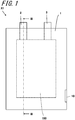
FIG. 1 is a top view of an example of an electrochemical cell, as seen from a positive electrode; -
FIG. 2 is a schematic view showing stacked constituent components of the example of the electrochemical cell; -
FIG. 3 is a sectional view taken along the line III-III inFIG. 1 ; -
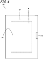
FIG. 4 is a top view of another example of the electrochemical cell, with terminals omitted, as seen from the positive electrode; -
FIG. 5 is a top view of the example of the electrochemical cell, with terminals omitted, as seen from a negative electrode; -
FIG. 6 is a top view of still another example of the electrochemical cell, as seen from the positive electrode; -
FIG. 7 is a top view of the example of the electrochemical cell, as seen from the negative electrode; -
FIG. 8 is a top view of still another example of the electrochemical cell, as seen from the positive electrode; -
FIG. 9 is a top view of the example of the electrochemical cell, as seen from the negative electrode; -
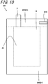
FIG. 10 is a top view of still another example of the electrochemical cell, as seen from the positive electrode; -
FIG. 11 is a top view of the example of the electrochemical cell, as seen from the negative electrode; -
FIG. 12 is a top view of still another example of the electrochemical cell, as seen from the positive electrode; -
FIG. 13 is a top view of the example of the electrochemical cell, as seen from the negative electrode; -
FIG. 14 is a top view of an example of the electrochemical cell stack, as seen from the positive electrode; and -
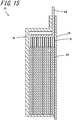
FIG. 15 is a sectional view taken along the line XV-XV inFIG. 14 . - As shown in
FIGS. 1 to 3 , an electrochemical cell X1 includes: a power-generatingelement 100 including a positive-electrode terminal 2, a negative-electrode terminal 3, a positive-electrode current collector 4, a semi-solidpositive electrode 5, a negative-electrodecurrent collector 6, a semi-solidnegative electrode 7, and aseparator 8; and apackaging body 1 which encases the power-generatingelement 100. - As employed herein "semi-solid" refers to a liquid phase-solid phase mixture, such as a particulate suspension, a colloidal suspension, an emulsion, a gel, or a micelle, for example.
- The
packaging body 1 is a member for encasing the positive-electrodecurrent collector 1 and the negative-electrodecurrent collector 6. More specifically, thepackaging body 1 receives therein part of the positive-electrode terminal 2, part of the negative-electrode terminal 3, the positive-electrodecurrent collector 4, thepositive electrode 5, the negative-electrodecurrent collector 6, thenegative electrode 7, and theseparator 8. Thepackaging body 1 includes ahole 10 which opens on an inner side of thepackaging body 1 and an outer side of thepackaging body 1. - The
packaging body 1 has a three-layer structure, for example. For example, the three-layer structure includes an external layer, an internal layer, and an intermediate layer sandwiched between the external layer and the internal layer. The internal layer makes contact with the positive-electrodecurrent collector 4 and the negative-electrodecurrent collector 6. This can improve the strength of thepackaging body 1. - For example, the external layer of the
packaging body 1 may contain an insulating material. The external layer of thepackaging body 1 may include a polymer film made of, for example, polyethylene terephthalate (PET), polybutylene terephthalate (PBT), nylon, high-purity polyethylene (HDPE), oriented polypropylene (o-PP), polyvinyl chloride (PVC), polyimide (PI), or polysulfone (PSU). Alternatively, the external layer of thepackaging body 1 may contain a combination of such materials as described above, for example. Moreover, the external layer of thepackaging body 1 may be coated with a combustion inhibitor, such as flame-retardant PET. - For example, the intermediate layer of the
packaging body 1 may contain a metal material. The intermediate layer of thepackaging body 1 may include a metallic layer (e.g. metallic foil, a metallic substrate, or a metallic film) made of, for example, aluminum (Al), copper (Cu), or stainless steel (SUS). Alternatively, the intermediate layer of thepackaging body 1 may include a metallic layer made of an alloy of such metals as described above, or a metallic layer made of a combination of such metals as described above. - For example, the internal layer of the
packaging body 1 may contain an insulating material. The internal layer of thepackaging body 1 may include a polymer film made of, for example, cast polypropylene (c-PP), polyethylene (PE), ethylene vinyl acetate (EVA), PET, polyvinyl acetate (PVA), polyamide (PA), an acrylic adhesive, an ultraviolet (UV)-curable resin, an electron beam (EB)-curable resin, or an infrared (IR)-curable resin. Alternatively, the internal layer of thepackaging body 1 may include a combination of polymer films of different materials as described above. - The internal layer of the
packaging body 1 may additionally contain a flame-retardant material, for example. The internal layer of thepackaging body 1 may contain, for example, polyether ether ketone (PEEK), polyethylene naphthalate (PEN), polyether sulfone (PES), PI, polyethylene sulfide (PPS), or polyethylene oxide (PPO). The internal layer of thepackaging body 1 may include a combination of flame-retardant films of different materials as described above. - The
packaging body 1 may have a two-layer structure, for example. For example, the two-layer structure includes an external layer and an internal layer. The external layer may include a polymer film made of, for example, PET or PBT. The internal layer may include a polymer film made of, for example, PP or PE. - The
packaging body 1 may have a single-layer structure, for example. For example, the single-layer structure may contain polypropylene or polyolefin. - In order to reduce the risk of catching fire, the single-layer structure of the
packaging body 1 may be made of a combustion-inhibiting substance. - The positive-electrode
current collector 4 transfers and receives electrons to and from thepositive electrode 5. The positive-electrodecurrent collector 4 includes a first plane P1. The first plane P1 of the positive-electrodecurrent collector 4 is electrically connected to thepositive electrode 5. A plane of the positive-electrodecurrent collector 4 opposite to the first plane P1 is connected to thepackaging body 1. For example, the positive-electrodecurrent collector 4 may be shaped in a sheet or mesh. The positive-electrodecurrent collector 4 contains a metal material, for example. The positive-electrodecurrent collector 4 may contain, for example, stainless steel, nickel, a nickel-chromium alloy, aluminum, titanium, copper, lead, a lead alloy, a refractory metal, or a precious metal. Moreover, the metal material constituting the positive-electrodecurrent collector 4 may be coated with an electrically conductive material. For example, a metal, a metallic oxide, or carbon may be used as the conductive material. For example, Pt, Au, or Ni may be used as the metal adopted as the conductive material. For example, vanadium oxide may be used as the metallic oxide adopted as the conductive material. For example, the positive-electrodecurrent collector 4measures 1 to 40 µm in thickness. - The negative-electrode
current collector 6 transfers and receives electrons to and from thenegative electrode 7. The negative-electrodecurrent collector 6 includes a second plane P2. The second plane P2 of the negative-electrodecurrent collector 6 is electrically connected to thenegative electrode 7. The plane of the negative-electrodecurrent collector 6 opposite to the second plane P2 is connected to thepackaging body 1. For example, the negative-electrodecurrent collector 6 may be shaped in a sheet or mesh. The negative-electrodecurrent collector 6 contains a metal, for example. The negative-electrodecurrent collector 6 may contain, for example, stainless steel, nickel, a nickel-chromium alloy, titanium, lead oxide, or a precious metal. For example, the negative-electrodecurrent collector 6measures 1 to 20 µm in thickness. - The semi-solid
positive electrode 5 receives electrons from the positive-electrodecurrent collector 4 during discharging process. Thepositive electrode 5 releases electrons to the positive-electrodecurrent collector 4 during charging process. Thepositive electrode 5 is electrically connected to the first plane P1 of the positive-electrodecurrent collector 4. - The semi-solid
negative electrode 7 releases electrons to the negative-electrodecurrent collector 6 during discharging process. Thenegative electrode 7 receives electrons from the negative-electrodecurrent collector 6 during charging process. Thenegative electrode 7 is electrically connected to the second plane P2 of the negative-electrodecurrent collector 6. - The
positive electrode 5 and thenegative electrode 7 are each an electrochemically active semi-solid member. For example, thepositive electrode 5 and thenegative electrode 7 may contain an active material and an electrolyte. For example, a solvent or solvent mixture with salt added may be used as the electrolyte. Thepositive electrode 5 and thenegative electrode 7 may contain an additive. For example, thepositive electrode 5 and thenegative electrode 7 may contain an active material, a composition, and a semi-solid suspension as described inU.S. Provisional Patent Application No. 61/787,382 U.S. Provisional Patent Application No. 61/787,372 - For example, the
positive electrode 5 and thenegative electrode 7 each measure 250 to 2000 µm in thickness. - The
separator 8 is disposed between thepositive electrode 5 and thenegative electrode 7 and divides the power-generatingelement 100 into a positive electrode 5-side portion and a negative electrode 7-side portion. Theseparator 8 reduces the possibility of short-circuiting within the power-generatingelement 100. Theseparator 8 includes an insulator. Theseparator 8 may contain, for example, a ductile and elastic polymer. More specifically, theseparator 8 may contain, for example, polyolefin, polyvinyl chloride, nylon, fluorocarbon, or polystyrene. - The
hole 10 allows gas generated by side reaction occurring in charging and discharging process to escape out of thepackaging body 1. For example, thehole 10 may be given a rectangular shape including long sides and short sides, as seen in a direction perpendicular to the first plane P1 of the positive-electrodecurrent collector 4. In this case, for example, thehole 10 is placed so that the long side thereof extends along the end of thepackaging body 1. Thehole 10 may be obtained by cutting away part of thepackaging body 1. Thehole 10 may also be obtained by forming a cutout in part of thepackaging body 1. For example, thehole 10 measures 0.1 to 10 mm in transverse length, and 10 to 30 mm in longitudinal length. - As shown in
FIGS. 1 to 3 , in the electrochemical cell X1 as exemplified in the disclosure, thepackaging body 1 includes thehole 10 which opens on an inner side of thepackaging body 1 and an outer side of thepackaging body 1. - Thus, the gas generated within the
packaging body 1 can be discharged out of thepackaging body 1, in consequence whereof there results little gas buildup between the positive-electrodecurrent collector 4 and thepositive electrode 5, between the negative-electrodecurrent collector 6 and thenegative electrode 7, and between thepositive electrode 5 and theseparator 8, or between thenegative electrode 7 and theseparator 8. This reduces a decline in efficiency in main reaction occurring in charging and discharging process, and thus reduces a decrease in battery capacity. - Moreover, as shown in
FIG. 3 , thepackaging body 1 includes afirst packaging portion 11 for covering the positive-electrodecurrent collector 4, and asecond packaging portion 12 for covering the negative-electrodecurrent collector 6. As shown inFIG. 2 , thehole 10 may be positioned in each of thefirst packaging portion 11 and thesecond packaging portion 12. In this case, while gas is generated within thepackaging body 1, a part of the gas from thepositive electrode 5 and a part of the gas from thenegative electrode 7 are each able to escape through the corresponding one of theholes 10, in consequence whereof there results little gas buildup between the positive-electrodecurrent collector 4 and thepositive electrode 5, between the negative-electrodecurrent collector 6 and thenegative electrode 7, and between thepositive electrode 5 and theseparator 8, or between thenegative electrode 7 and theseparator 8. This reduces a decline in efficiency in main reaction occurring in charging and discharging process. Thus, this can reduce a decrease in battery capacity. - The following are examples of how the
hole 10 is to be positioned. That is, thehole 10 may be placed so that the long side thereof extends along one side of the outer periphery of thefirst packaging portion 11, as seen in a direction perpendicular to the first plane P1 of the positive-electrodecurrent collector 4. Moreover, thehole 10 may be placed so that the long side thereof extends along one side of the outer periphery of thesecond packaging portion 12, as seen in a direction perpendicular to the second plane P2 of the negative-electrodecurrent collector 6. - As shown in
FIG. 4 , in an electrochemical cell X2, the positive-electrodecurrent collector 4 includes a first plane P1 opposed to thepositive electrode 5. In this construction, thepackaging body 1 includes a first region E1 which does not overlap with the positive-electrodecurrent collector 4, as seen in a direction perpendicular to the first plane P1. More specifically, the positive-electrodecurrent collector 4 may be given a quadrangular shape, and thepackaging body 1 may be given a rectangular shape which is larger than the positive-electrodecurrent collector 4, as seen in a direction perpendicular to the first plane P1. - The term "quadrangular shape" may be construed as encompassing a rounded quadrangle. Moreover, the term "rectangular shape" may be construed as encompassing a rounded rectangle.
- A
hole 110 is positioned in the first region E1. This can facilitate an escape of gas generated at thepositive electrode 5. That is, if thehole 110 is positioned in a region which overlaps with thepositive electrode 5, the gas generated at thepositive electrode 5 will travel to the first region E1 first, then travel from the first region E1 to the region which overlaps with thepositive electrode 5, and will eventually go out through thehole 110. In contrast, with thehole 110 positioned in the first region E1, the gas generated at thepositive electrode 5 travels to the first region E1, and immediately afterwards goes out through thehole 110. In fact, the positioning of thehole 110 in the first region E1 can achieve smooth escape of the gas generated at thepositive electrode 5 through thehole 110. - For example, the
hole 110 may lie in the bisector passing through the quadrangular positive-electrodecurrent collector 4. As employed herein "the bisector passing through the positive-electrodecurrent collector 4" refers to a straight line passing through the midpoint of each of the two opposed sides of the positive-electrodecurrent collector 4. - As shown in
FIG. 5 , in the electrochemical cell X2, the negative-electrodecurrent collector 6 includes a second plane P2 opposed to thenegative electrode 7. Thepackaging body 1 includes a second region E2 which does not overlap with the negative-electrodecurrent collector 6, as seen in a direction perpendicular to the second plane P2. More specifically, the negative-electrodecurrent collector 6 may be quadrangular shaped, and thepackaging body 1 may be given a rectangular shape which is larger than the negative-electrodecurrent collector 6, as seen in a direction perpendicular to the second plane P2. - A
hole 110 is positioned in the second region E2. This can facilitate an escape of gas generated at thenegative electrode 6. That is, if thehole 110 is positioned in a region which overlaps with thenegative electrode 6, the gas generated at thenegative electrode 6 will travel to the second region E2 first, then travel from the second region E2 to the region which overlaps with thenegative electrode 6, and will eventually go out through thehole 110. In contrast, with thehole 110 positioned in the second region E2, the gas generated at thenegative electrode 6 travels to the second region E2, and immediately afterwards goes out through thehole 110. In fact, the positioning of thehole 110 in the second region E2 can achieve smooth escape of the gas generated at thenegative electrode 6 through thehole 110. - For example, the
hole 110 may lie in the bisector passing through the negative-electrodecurrent collector 6. As employed herein "the bisector passing through the negative-electrodecurrent collector 6" refers to a straight line passing through the midpoint of each of the two opposed sides of the negative-electrodecurrent collector 6. - As shown in
FIGS. 6 and7 , an electrochemical cell X3 additionally includes a positive-electrode terminal 2 and a negative-electrode terminal 3. - In this construction, for example, as shown in
FIG. 6 , the positive-electrodecurrent collector 4 may be given a quadrangular shape including a first side L1, as seen in a direction perpendicular to the first plane P1. Thepackaging body 1 may be given a rectangular shape which is larger than the positive-electrodecurrent collector 4. - The positive-
electrode terminal 2 includes a first end and a second end. The first end of the positive-electrode terminal 2 is connected to the first side L1 of the positive-electrodecurrent collector 5 within thepackaging body 1. The positive-electrode terminal 2 provides electrical connection between the electrochemical cell X3 and an external apparatus. For example, the positive-electrode terminal 2 may be made of the same material as that used for the positive-electrodecurrent collector 4. Alternatively, the positive-electrode terminal 2 may be made of a material which is different from that used for the positive-electrodecurrent collector 4. The positive-electrode terminal 2, when it differs in material from the positive-electrodecurrent collector 4, may contain a metal material. For example, copper, nickel, or gold may be used as the metal material. - Moreover, as shown in
FIG. 8 , a positive-electrode terminal 302 and the positive-electrodecurrent collector 4 may be formed as a single member. In other words, the positive-electrodecurrent collector 4 and the positive-electrode terminal 302 may be included in a single member. Moreover, as shown inFIG. 9 , a negative-electrode terminal 303 and the negative-electrodecurrent collector 6 may be formed as a single member. In other words, the negative-electrodecurrent collector 6 and the positive-electrode terminal 303 may be included in a single member. For example, the positive-electrode terminal 2 may be rectangular shaped. In this case, one of the short sides of the positive-electrode terminal 2 may overlap with the first side L1 of the positive-electrodecurrent collector 4. - For example, as shown in
FIG. 7 , the negative-electrodecurrent collector 6 may be given a quadrangular shape including a second side L2, as seen in a direction perpendicular to the second plane P2. Thepackaging body 1 may be given a rectangular shape which is larger than the negative-electrodecurrent collector 6. - The negative-
electrode terminal 3 includes a first end and a second end. The first end of the negative-electrode terminal 3 is connected to the second side L2 of the negative-electrodecurrent collector 6 within thepackaging body 1. The negative-electrode terminal 3 provides electrical connection between the electrochemical cell X3 and an external apparatus. For example, the negative-electrode terminal 3 may be made of the same material as that used for the negative-electrodecurrent collector 6. Alternatively, the negative-electrode terminal 3 may be made of a material which is different from that used for the negative-electrodecurrent collector 6. The negative-electrode terminal 3, when it differs in material from the negative-electrodecurrent collector 6, may contain a metal material. For example, aluminum, nickel, or gold may be used as the metal material. For example, the negative-electrode terminal 3 may be rectangular shaped. In this case, one of the short sides of the negative-electrode terminal 3 may overlap with the second side L2 of the negative-electrodecurrent collector 6. - As shown in
FIG. 6 , in the electrochemical cell X3, the first region E1 includes a third region E3 and a fourth region E4. Given that the first region E1 is divided into two subregions by a straight line extending from a side opposite to the first side L1 of the positive-electrodecurrent collector 4, the third region E3 corresponds to one of the subregions from which the positive-electrode terminal 2 is exposed, and, the fourth region E4 corresponds to the other subregion which is an area of the first region E1 exclusive of the third region E3. - A
hole 210 is positioned in the fourth region E4. For example, thehole 210 may be positioned at a corner of the fourth region E4 of thepackaging body 1. As employed herein "positioning of the hole at a corner" refers to an absence of a corner resulting from the placement of thehole 210. The term "absence of a corner" encompasses, in addition to the removal of an originally existing corner of thepackaging body 1, thepackaging body 1 is free of any corners. This arrangement can increase the distance between thehole 210 and the positive-electrode terminal 2. Thus, this can reduce the tendency of the positive-electrode terminal 2 to short-circuit against thenegative electrode 7 via thehole 210. - Moreover, as shown in
FIG. 7 , in the electrochemical cell X3, the second region E2 includes a fifth region E5 and a sixth region E6. Given that the second region E2 is divided into two subregions by a straight line extending from a side opposite to the second side L2 of the negative-electrodecurrent collector 6, the fifth region E5 corresponds to that one of the subregions from which the negative-electrode terminal 3 is exposed, and, the sixth region E6 corresponds to the other subregion which is an area of the second region E2 exclusive of the fifth region E5. - A
hole 210 is positioned in the sixth region E6. For example, thehole 210 may be positioned at a corner of the sixth region E6 of thepackaging body 1. As employed herein "positioning of the hole at a corner" refers to an absence of a corner resulting from the placement of thehole 210. The term "absence of a corner" encompasses, in addition to the removal of an originally existing corner of thepackaging body 1, thepackaging body 1 is free of any corners. This arrangement can increase the distance between thehole 210 and the negative-electrode terminal 3. Thus, this can reduce the tendency of the negative-electrode terminal 3 to short-circuit against thepositive electrode 5 via thehole 210. - As shown in
FIG. 8 orFIG. 9 , the positive-electrodecurrent collector 4 is quadrangular shaped, as seen in a direction perpendicular to the first plane P1. The positive-electrodecurrent collector 4 includes a first corner S1 and a second corner S2 which is positioned on a diagonal line of the positive-electrodecurrent collector 4 with respect to the first corner S1. The positive-electrode terminal 302 is positioned in the vicinity of the first corner S1. The second end of the positive-electrode terminal 302 is exposed out of thepackaging body 1. Ahole 310 is positioned in the vicinity of the second corner S2. - As shown in
FIG. 8 , given that thepackaging body 1 is divided into four regions by an imaginary line passing through the midpoint of one specific side of the positive-electrodecurrent collector 4 and an imaginary line passing through the midpoint of another side of the positive-electrodecurrent collector 4 contiguous to the specific side, the term "the vicinity of the first corner S1" described above refers to the region including the first corner S1 where the positive-electrode terminal 302 is positioned, and, the term "the vicinity of the second corner S2" described above refers to the region including the second corner S2 where thehole 310 is positioned. - Thus, the
hole 310 and the positive-electrode terminal 302 can be positioned on a diagonal line of the quadrangular positive-electrodecurrent collector 4. This arrangement increases the distance between thehole 310 and the positive-electrode terminal 302, and thus reduces the tendency of the positive-electrode terminal 302 to short-circuit against thenegative electrode 7 via thehole 310. - The negative-electrode
current collector 6 is quadrangular shaped, as seen in a direction perpendicular to the second plane P2. The negative-electrodecurrent collector 6 includes a third corner S3 and a fourth corner S4 which is positioned on a diagonal line of the negative-electrodecurrent collector 6 with respect to the third corner S3. The negative-electrode terminal 303 is positioned in the vicinity of the third corner S3. The second end of the negative-electrode terminal 303 is exposed out of thepackaging body 1. Ahole 310 is positioned in the vicinity of the fourth corner S4. - As shown in
FIG. 9 , given that thepackaging body 1 is divided into four regions by an imaginary line passing through the midpoint of one specific side of the negative-electrodecurrent collector 6 and an imaginary line passing through the midpoint of another side of the negative-electrodecurrent collector 6 intersecting with the one specific side, the term "the vicinity of the third corner S3" described above refers to a region including the third corner S3 where the negative-electrode terminal 303 is positioned, and, the term "the vicinity of the fourth corner S4" described above refers to a region including the fourth corner S4 where thehole 310 is positioned. - Thus, the
hole 310 and the negative-electrode terminal 303 can be positioned on a diagonal line of the quadrangular negative-electrodecurrent collector 6. This arrangement can increase the distance between thehole 310 and the negative-electrode terminal 303. Thus, this can reduce the tendency of the negative-electrode terminal 303 to short-circuit against thepositive electrode 5 via thehole 310. - As shown in
FIG. 10 , in an electrochemical cell X5, the positive-electrodecurrent collector 4 is given a quadrangular shape including a first side L1, as seen in a direction perpendicular to the first plane P1. The first end of the positive-electrode terminal 2 is connected to the first side L1 within thepackaging body 1. The second end of the positive-electrode terminal 2 is exposed out of thepackaging body 1. The first region E1 of thepackaging body 1 is divided, by a straight line extending from the first side L1, into a seventh region E7 from which the positive-electrode terminal 2 is exposed, and an eighth region E8 which is an other region than the seventh region E7. - A
hole 410 is positioned in the seventh region E7. For example, thehole 410 may be positioned at a corner of the seventh region E7 of thequadrangular packaging body 1. In this case, thehole 410 can be brought nearer to the positive-electrode terminal 2 which is prone to gas generation, and this can facilitate an escape of gas to the outside. Thus, this can achieve further reduction in decreased battery capacity. Gas is generated more readily at and around the positive-electrode terminal 2, presumably because, for example, this region is more likely to undergo the passage of electric current. - Moreover, as shown in
FIG. 11 , in the electrochemical cell X5, the negative-electrodecurrent collector 6 is given a quadrangular shape including a second side L2, as seen in a direction perpendicular to the second plane P2. The first end of the negative-electrode terminal 3 is connected to the second side L2 within thepackaging body 1. The second end of the negative-electrode terminal 3 is exposed out of thepackaging body 1. The second region E2 of thepackaging body 1 is divided, by a straight line extending from the second side L2, into a ninth region E9 from which the negative-electrode terminal 3 is exposed, and a tenth region E10 which is an other region than the ninth region E9. - A
hole 410 is positioned in the ninth region E9. For example, thehole 410 may be positioned at a corner of the ninth region E9 of thequadrangular packaging body 1. In this case, thehole 410 can be brought nearer to the negative-electrode terminal 3 which is prone to gas generation, and this can facilitate an escape of gas to the outside. Thus, this can achieve further reduction in decreased battery capacity. Gas is generated more readily at and around the negative-electrode terminal 3, presumably because, for example, this region is more likely to undergo the passage of electric current. - As shown in
FIG. 12 , an electrochemical cell X6 includes an eleventh region E11 in which the first plane P1 of the positive-electrodecurrent collector 4 and the second plane P2 of the negative-electrodecurrent collector 6 overlap with each other, as seen in a direction perpendicular to the first plane P1. Thepackaging body 1 includes a twelfth region E12. The twelfth region E12 is a region in which an extension region of the eleventh region E11 extending toward the exposed portion of the positive-electrode terminal 2 and the seventh region E7 overlap with each other. Ahole 510 is positioned in the twelfth region E12. - Moreover, as shown in
FIG. 13 , in the electrochemical cell X6, the negative-electrodecurrent collector 6 includes a thirteenth region E13 in which the first plane P1 of the positive-electrodecurrent collector 4 and the second plane P2 of the negative-electrodecurrent collector 6 overlap with each other, as seen in a direction perpendicular to the second plane P1. Thepackaging body 1 includes a fourteenth region E14. The fourteenth region E14 is a region in which an extension region of the thirteenth region E13 extending toward the connected negative-electrode terminal 3 and the ninth region E9 overlap with each other. Ahole 510 is positioned in the fourteenth region E14. - This arrangement can facilitate an escape of gas present around the gas generation-prone region where the positive-electrode
current collector 4 and the negative-electrodecurrent collector 6 overlap with each other. Thus, this can achieve further reduction in decreased battery capacity. - An electrochemical cell stack Z1 will now be described with reference to
FIGS. 14 and15 . As shown inFIGS. 14 and15 , the electrochemical cell stack Z1 includes a plurality of electrochemical cells X1 received in ahousing 13. - The
housing 13 isolates the plurality of electrochemical cells X1 from the surrounding environment. This can reduce leakage of the substances constituting thepositive electrode 5 or thenegative electrode 7 from the plurality of electrochemical cells X1 to the surrounding environment. Also this can reduce infiltration of water and oxygen from the surrounding environment into the plurality of electrochemical cells X1. Thehousing 13 may be shaped in a rectangular prism, for example. Moreover, thehousing 13 may be made of a metal material, for example. Examples of the metal material include stainless steel, aluminum, and copper. Thehousing 13 may contain an alloy of such metals as described above, or a combination of such metals as described above. Thehousing 13 is slightly larger in dimensions than the electrochemical cell X1. - Moreover, as shown in
FIGS. 14 and15 , a positive-electrode terminal extension 14 connected to a plurality of positive-electrode terminals 2 and a negative-electrode terminal extension 15 connected to a plurality of negative-electrode terminals 3 provide electrical connection between an external apparatus and the plurality of electrochemical cells X1 received inside thehousing 13. Moreover, the positive-electrode terminal extension 14 and the negative-electrode terminal extension 15 each include a first end and a second end. The first end of the positive-electrode terminal extension 14 is electrically connected to the plurality of positive-electrode terminals 2 within thehousing 13, and, the first end of the negative-electrode terminal extension 15 is electrically connected to the plurality of negative-electrode terminals 3 within thehousing 13. The second end of the positive-electrode terminal extension 14, as well as the second end of the negative-electrode terminal extension 15, is exposed out of thehousing 13. -
- X1 to X6:
- Electrochemical cell
- Z1:
- Electrochemical cell stack
- 1:
- Packaging body
- 2:
- Positive-electrode terminal
- 3:
- Negative-electrode terminal
- 4:
- Positive-electrode current collector
- 5:
- Positive electrode
- 6:
- Negative-electrode current collector
- 7:
- Negative electrode
- 8:
- Separator
- 10, 110, 210, 310, 410, 510:
- Hole
- 100:
- Power-generating element
Claims (13)
- An electrochemical cell, comprising:a power-generating element comprisinga semi-solid positive electrode,a semi-solid negative electrode,a separator located between the semi-solid positive electrode and the semi-solid negative electrode,a positive-electrode current collector electrically connected to the semi-solid positive electrode, anda negative-electrode current collector electrically connected to the semi-solid negative electrode; anda packaging body which encases the power-generating element, the packaging body comprising single or plural holes which open on an inner side of the packaging body and an outer side of the packaging body.
- The electrochemical cell according to claim 1,
wherein the packaging body comprises a first packaging portion which covers the positive-electrode current collector, and a second packaging portion which covers the negative-electrode current collector,
the packaging body comprises plural holes which open on an inner side of the packaging body and an outer side of the packaging body, and
at least one of the plurality of holes is positioned in the first packaging portion, and, at least one of the plurality of holes is positioned in the second packaging portion. - The electrochemical cell according to claim 1 or 2,
wherein the positive-electrode current collector comprises a first plane opposed to the semi-solid positive electrode,
the packaging body comprises a first region which does not overlap with the positive-electrode current collector, as seen in a direction perpendicular to the first plane, and
the single or plural holes are positioned in the first region. - The electrochemical cell according to any one of claims 1 to 3,
wherein the negative-electrode current collector comprises a second plane opposed to the semi-solid negative electrode,
the packaging body comprises a second region which does not overlap with the negative-electrode current collector, as seen in a direction perpendicular to the second plane, and
the single or plural holes are positioned in the second region. - The electrochemical cell according to claim 3, further comprising:a positive-electrode terminal electrically connected to the positive-electrode current collector,wherein, when viewed in a direction perpendicular to the first plane,the positive-electrode current collector is given a quadrangular shape comprising a first side,the positive-electrode terminal comprises a first end and a second end, the first end being connected to the first side within the packaging body, the second end being exposed out of the packaging body,the first region is divided, by a straight line extending from a side opposite to the first side of the positive-electrode current collector, into a third region from which the positive-electrode terminal is exposed and a fourth region which is an other region than the third region, andthe single or plural holes are positioned in the fourth region.
- The electrochemical cell according to claim 4, further comprising:a negative-electrode terminal electrically connected to the negative-electrode current collector,wherein, when viewed in a direction perpendicular to the second plane,the negative-electrode current collector is given a quadrangular shape comprising a second side,the negative-electrode terminal comprises a first end and a second end, the first end being connected to the second side within the packaging body, the second end being exposed out of the packaging body,the second region is divided, by a straight line extending from a side opposite to the second side of the negative-electrode current collector, into a fifth region from which the negative-electrode terminal is exposed and a sixth region which is an other region than the fifth region, andthe single or plural holes are positioned in the sixth region.
- The electrochemical cell according to claim 3, further comprising:a positive-electrode terminal electrically connected to the positive-electrode current collector, the positive-electrode terminal comprising a first end and a second end,wherein, when viewed in a direction perpendicular to the first plane,the positive-electrode current collector is given a quadrangular shape comprising a first corner and a second corner which is positioned on a diagonal line of the positive-electrode current collector with respect to the first corner,in the positive-electrode terminal, the first end is connected to the positive-electrode current collector in a vicinity of the first corner within the packaging body, and the second end is exposed out of the packaging body, andthe single or plural holes are positioned in a vicinity of the second corner.
- The electrochemical cell according to claim 4, further comprising:a negative-electrode terminal electrically connected to the negative-electrode current collector, the negative-electrode terminal comprising a first end and a second end,wherein, when viewed in a direction perpendicular to the second plane,the negative-electrode current collector is given a quadrangular shape comprising a third corner and a fourth corner which is positioned on a diagonal line of the negative-electrode current collector with respect to the third corner,in the negative-electrode terminal, the first end is connected to the negative-electrode current collector in a vicinity of the third corner within the packaging body, and the second end is exposed out of the packaging body, andthe single or plural holes are positioned in a vicinity of the fourth corner.
- The electrochemical cell according to claim 3, further comprising:a positive-electrode terminal electrically connected to the positive-electrode current collector, the positive-electrode terminal comprising a first end and a second end,wherein, when viewed in a direction perpendicular to the first plane,the positive-electrode current collector is given a quadrangular shape comprising a first side,in the positive-electrode terminal, the first end is connected to the first side within the packaging body, and the second end is exposed out of the packaging body,the first region is divided, by a straight line extending from the first side, into a seventh region from which the positive-electrode terminal is exposed and an eighth region which is an other region than the seventh region, andthe single or plural holes are positioned in the seventh region.
- The electrochemical cell according to claim 4, further comprising:a negative-electrode terminal electrically connected to the negative-electrode current collector, the negative-electrode terminal comprising a first end and a second end,wherein, when viewed in a direction perpendicular to the second plane,the negative-electrode current collector is given a quadrangular shape comprising a second side,in the negative-electrode terminal, the first end is connected to the second side within the packaging body, and the second end is exposed out of the packaging body,the second region is divided, by a straight line extending from the second side, into a ninth region from which the negative-electrode terminal is exposed and a tenth region which is an other region than the ninth region, andthe single or plural holes are positioned in the ninth region.
- The electrochemical cell according to claim 9,
wherein, when viewed in a direction perpendicular to the first plane,
the negative-electrode current collector is given a quadrangular shape comprising a second plane,
the positive-electrode current collector comprises an eleventh region in which the first plane and the second plane overlap with each other,
the packaging body comprises a twelfth region in which an extension region of the eleventh region extending toward an exposed portion of the positive-electrode terminal and the seventh region overlap with each other, and
the single or plural holes are positioned in the twelfth region. - The electrochemical cell according to claim 10,
wherein, when viewed in a direction perpendicular to the second plane,
the positive-electrode current collector is given a quadrangular shape comprising a first plane,
the negative-electrode current collector comprises a thirteenth region in which the first plane and the second plane overlap with each other,
the packaging body comprises a fourteenth region in which an extension region of the thirteenth region extending toward an exposed portion of the negative-electrode terminal and the ninth region overlap with each other, and
the single or plural holes are positioned in the fourteenth region. - An electrochemical cell stack, comprising:
a plurality of electrochemical cells according to any one of claims 1 to 12.
Applications Claiming Priority (2)
| Application Number | Priority Date | Filing Date | Title |
|---|---|---|---|
| JP2017209197 | 2017-10-30 | ||
| PCT/JP2018/039857 WO2019087956A1 (en) | 2017-10-30 | 2018-10-26 | Electrochemical cell and electrochemical cell stack |
Publications (2)
| Publication Number | Publication Date |
|---|---|
| EP3706195A1 true EP3706195A1 (en) | 2020-09-09 |
| EP3706195A4 EP3706195A4 (en) | 2021-08-11 |
Family
ID=66331770
Family Applications (1)
| Application Number | Title | Priority Date | Filing Date |
|---|---|---|---|
| EP18874920.4A Pending EP3706195A4 (en) | 2017-10-30 | 2018-10-26 | ELECTROCHEMICAL CELL AND STACKING OF ELECTROCHEMICAL CELLS |
Country Status (5)
| Country | Link |
|---|---|
| US (1) | US12519176B2 (en) |
| EP (1) | EP3706195A4 (en) |
| JP (1) | JP7005649B2 (en) |
| CN (1) | CN111263990A (en) |
| WO (1) | WO2019087956A1 (en) |
Cited By (2)
| Publication number | Priority date | Publication date | Assignee | Title |
|---|---|---|---|---|
| WO2023094582A1 (en) * | 2021-11-29 | 2023-06-01 | Fraunhofer-Gesellschaft zur Förderung der angewandten Forschung e.V. | Housing for storing an aluminum chloride-containing ionic liquid, and battery cell comprising such a housing |
| EP4329024A4 (en) * | 2021-04-21 | 2025-06-11 | Kyocera Corporation | Method for producing electrochemical cell |
Families Citing this family (3)
| Publication number | Priority date | Publication date | Assignee | Title |
|---|---|---|---|---|
| US11923511B2 (en) | 2019-07-12 | 2024-03-05 | Electrochem Solutions, Inc. | Lithium oxyhalide electrochemical cell design for high-rate discharge |
| CN110828744B (en) | 2020-01-13 | 2020-07-10 | 比亚迪股份有限公司 | Battery, battery pack and electric vehicle |
| WO2022224386A1 (en) | 2021-04-21 | 2022-10-27 | 京セラ株式会社 | Method for manufacturing electrochemical cell |
Family Cites Families (19)
| Publication number | Priority date | Publication date | Assignee | Title |
|---|---|---|---|---|
| JP4862211B2 (en) | 2000-08-08 | 2012-01-25 | 株式会社Gsユアサ | Sealed secondary battery |
| US6503658B1 (en) * | 2001-07-11 | 2003-01-07 | Electro Energy, Inc. | Bipolar electrochemical battery of stacked wafer cells |
| JP4860181B2 (en) * | 2005-05-20 | 2012-01-25 | Necエナジーデバイス株式会社 | Film exterior battery |
| JPWO2007043392A1 (en) * | 2005-10-03 | 2009-04-16 | Tdkラムダ株式会社 | Battery pack |
| US8956743B2 (en) * | 2006-08-28 | 2015-02-17 | Lg Chem, Ltd. | Secondary battery including one-way exhaust member |
| JP5178606B2 (en) * | 2009-03-31 | 2013-04-10 | Jmエナジー株式会社 | Laminate exterior power storage device |
| JP2010238861A (en) * | 2009-03-31 | 2010-10-21 | Jm Energy Corp | Laminate exterior power storage device |
| US20110123844A1 (en) * | 2009-11-20 | 2011-05-26 | Apple Inc. | Pressure-relief mechanism to improve safety in lithium-polymer battery cells |
| JP2011198742A (en) * | 2010-02-26 | 2011-10-06 | Hitachi Maxell Energy Ltd | Laminated type battery |
| US20120045672A1 (en) * | 2010-08-23 | 2012-02-23 | Delphi Technologies, Inc. | Vented battery pack |
| KR20140013132A (en) | 2012-07-09 | 2014-02-05 | 에스케이이노베이션 주식회사 | Secondary battery |
| KR101547403B1 (en) | 2013-01-11 | 2015-08-25 | 주식회사 엘지화학 | Secondary battery comprising unified positive lead and negative lead and the method for preparing thereof |
| KR101620666B1 (en) | 2013-05-02 | 2016-05-12 | 주식회사 엘지화학 | Pouch type secondary battery having safety vent |
| KR101676406B1 (en) * | 2013-10-31 | 2016-11-15 | 주식회사 엘지화학 | Stack-folding typed electrode assembly |
| EP3161899A4 (en) * | 2014-06-30 | 2017-12-27 | Black & Decker Inc. | Battery pack for a cordless power tools |
| EP3216067B1 (en) * | 2014-11-05 | 2021-09-15 | 24m Technologies, Inc. | Electrochemical cells having semi-solid electrodes and methods of manufacturing the same |
| US9999024B2 (en) | 2015-01-08 | 2018-06-12 | Qualcomm Incorporated | Evolved multimedia broadcast multicast service (eMBMS) streaming loss control in a radio sharing concurrent radio access technology (RAT) capable mobile device |
| KR101904587B1 (en) | 2015-09-01 | 2018-10-04 | 주식회사 엘지화학 | Battery cell and method for manufacturing the same |
| CN119725968A (en) * | 2017-02-01 | 2025-03-28 | 24M技术公司 | Systems and methods for improving safety features in electrochemical cells |
-
2018
- 2018-10-26 CN CN201880068731.6A patent/CN111263990A/en active Pending
- 2018-10-26 US US16/760,017 patent/US12519176B2/en active Active
- 2018-10-26 JP JP2019550317A patent/JP7005649B2/en active Active
- 2018-10-26 WO PCT/JP2018/039857 patent/WO2019087956A1/en not_active Ceased
- 2018-10-26 EP EP18874920.4A patent/EP3706195A4/en active Pending
Cited By (2)
| Publication number | Priority date | Publication date | Assignee | Title |
|---|---|---|---|---|
| EP4329024A4 (en) * | 2021-04-21 | 2025-06-11 | Kyocera Corporation | Method for producing electrochemical cell |
| WO2023094582A1 (en) * | 2021-11-29 | 2023-06-01 | Fraunhofer-Gesellschaft zur Förderung der angewandten Forschung e.V. | Housing for storing an aluminum chloride-containing ionic liquid, and battery cell comprising such a housing |
Also Published As
| Publication number | Publication date |
|---|---|
| US12519176B2 (en) | 2026-01-06 |
| JPWO2019087956A1 (en) | 2020-11-19 |
| JP7005649B2 (en) | 2022-01-21 |
| US20200350537A1 (en) | 2020-11-05 |
| EP3706195A4 (en) | 2021-08-11 |
| CN111263990A (en) | 2020-06-09 |
| WO2019087956A1 (en) | 2019-05-09 |
Similar Documents
| Publication | Publication Date | Title |
|---|---|---|
| EP3706195A1 (en) | Electrochemical cell and electrochemical cell stack | |
| CN100483800C (en) | Electrode assembly and lithium ion secondary battery using the same | |
| JP4243409B2 (en) | Lithium secondary battery | |
| KR101147207B1 (en) | Electrode assembly, and rechargeable battery using thereof | |
| KR101629499B1 (en) | Electrode assembly and secondary battery comprising the same | |
| EP2602843A2 (en) | Pouch and pouch type secondary battery | |
| CN102386364A (en) | Secondary battery | |
| CN112331927B (en) | Battery lamination electricity core and battery | |
| EP3905416A1 (en) | Battery | |
| EP4395059A1 (en) | Battery cell with chamfered protective tape | |
| KR101629498B1 (en) | Electrode assembly and secondary battery comprising the same | |
| KR102888139B1 (en) | Electrode assembly and secondary battery comprising same | |
| US9012070B2 (en) | Secondary battery | |
| KR20220104809A (en) | Segmented membranes, battery combinations and electrical devices | |
| KR101600605B1 (en) | Electrode assembly with improved safety and secondary battery containing the same | |
| KR101431726B1 (en) | Electrode Assembly of Improved Safety And Secondary Battery with the Same | |
| KR102809160B1 (en) | The Electrode Assembly And The Pouch Type Secondary Battery | |
| KR100436714B1 (en) | Prismatic type lithium secondary battery | |
| US20030129488A1 (en) | Planar battery and method of sealing | |
| EP4418414A1 (en) | Pouch-type secondary battery, secondary battery module including same, and pouch used therefor | |
| JP7465340B2 (en) | Metal-air battery device | |
| JP4363558B2 (en) | Flat non-aqueous electrolyte secondary battery | |
| US20240213543A1 (en) | Method for manufacturing electrochemical cell | |
| US20030048093A1 (en) | Protective shield to prevent shorting in polymer battery | |
| KR100601563B1 (en) | Cylindrical Li-ion Secondary Battery |
Legal Events
| Date | Code | Title | Description |
|---|---|---|---|
| STAA | Information on the status of an ep patent application or granted ep patent |
Free format text: STATUS: THE INTERNATIONAL PUBLICATION HAS BEEN MADE |
|
| PUAI | Public reference made under article 153(3) epc to a published international application that has entered the european phase |
Free format text: ORIGINAL CODE: 0009012 |
|
| STAA | Information on the status of an ep patent application or granted ep patent |
Free format text: STATUS: REQUEST FOR EXAMINATION WAS MADE |
|
| 17P | Request for examination filed |
Effective date: 20200427 |
|
| AK | Designated contracting states |
Kind code of ref document: A1 Designated state(s): AL AT BE BG CH CY CZ DE DK EE ES FI FR GB GR HR HU IE IS IT LI LT LU LV MC MK MT NL NO PL PT RO RS SE SI SK SM TR |
|
| AX | Request for extension of the european patent |
Extension state: BA ME |
|
| DAV | Request for validation of the european patent (deleted) | ||
| DAX | Request for extension of the european patent (deleted) | ||
| REG | Reference to a national code |
Ref country code: DE Ref legal event code: R079 Free format text: PREVIOUS MAIN CLASS: H01M0002120000 Ipc: H01M0050342000 |
|
| A4 | Supplementary search report drawn up and despatched |
Effective date: 20210712 |
|
| RIC1 | Information provided on ipc code assigned before grant |
Ipc: H01M 50/342 20210101AFI20210706BHEP Ipc: H01M 50/105 20210101ALI20210706BHEP Ipc: H01M 50/55 20210101ALN20210706BHEP |
|
| P01 | Opt-out of the competence of the unified patent court (upc) registered |
Effective date: 20230508 |