EP3706193B1 - Protective case for batteries and method for the production of a protective case for batteries - Google Patents
Protective case for batteries and method for the production of a protective case for batteries Download PDFInfo
- Publication number
- EP3706193B1 EP3706193B1 EP20159756.4A EP20159756A EP3706193B1 EP 3706193 B1 EP3706193 B1 EP 3706193B1 EP 20159756 A EP20159756 A EP 20159756A EP 3706193 B1 EP3706193 B1 EP 3706193B1
- Authority
- EP
- European Patent Office
- Prior art keywords
- protective case
- batteries
- reinforcement
- multilayer structure
- shielding layer
- Prior art date
- Legal status (The legal status is an assumption and is not a legal conclusion. Google has not performed a legal analysis and makes no representation as to the accuracy of the status listed.)
- Active
Links
Images

Classifications
-
- B—PERFORMING OPERATIONS; TRANSPORTING
- B32—LAYERED PRODUCTS
- B32B—LAYERED PRODUCTS, i.e. PRODUCTS BUILT-UP OF STRATA OF FLAT OR NON-FLAT, e.g. CELLULAR OR HONEYCOMB, FORM
- B32B5/00—Layered products characterised by the non- homogeneity or physical structure, i.e. comprising a fibrous, filamentary, particulate or foam layer; Layered products characterised by having a layer differing constitutionally or physically in different parts
- B32B5/02—Layered products characterised by the non- homogeneity or physical structure, i.e. comprising a fibrous, filamentary, particulate or foam layer; Layered products characterised by having a layer differing constitutionally or physically in different parts characterised by structural features of a fibrous or filamentary layer
-
- B—PERFORMING OPERATIONS; TRANSPORTING
- B29—WORKING OF PLASTICS; WORKING OF SUBSTANCES IN A PLASTIC STATE IN GENERAL
- B29C—SHAPING OR JOINING OF PLASTICS; SHAPING OF MATERIAL IN A PLASTIC STATE, NOT OTHERWISE PROVIDED FOR; AFTER-TREATMENT OF THE SHAPED PRODUCTS, e.g. REPAIRING
- B29C70/00—Shaping composites, i.e. plastics material comprising reinforcements, fillers or preformed parts, e.g. inserts
- B29C70/04—Shaping composites, i.e. plastics material comprising reinforcements, fillers or preformed parts, e.g. inserts comprising reinforcements only, e.g. self-reinforcing plastics
- B29C70/06—Fibrous reinforcements only
- B29C70/08—Fibrous reinforcements only comprising combinations of different forms of fibrous reinforcements incorporated in matrix material, forming one or more layers, and with or without non-reinforced layers
- B29C70/086—Fibrous reinforcements only comprising combinations of different forms of fibrous reinforcements incorporated in matrix material, forming one or more layers, and with or without non-reinforced layers and with one or more layers of pure plastics material, e.g. foam layers
-
- B—PERFORMING OPERATIONS; TRANSPORTING
- B29—WORKING OF PLASTICS; WORKING OF SUBSTANCES IN A PLASTIC STATE IN GENERAL
- B29B—PREPARATION OR PRETREATMENT OF THE MATERIAL TO BE SHAPED; MAKING GRANULES OR PREFORMS; RECOVERY OF PLASTICS OR OTHER CONSTITUENTS OF WASTE MATERIAL CONTAINING PLASTICS
- B29B11/00—Making preforms
- B29B11/06—Making preforms by moulding the material
- B29B11/10—Extrusion moulding
-
- B—PERFORMING OPERATIONS; TRANSPORTING
- B29—WORKING OF PLASTICS; WORKING OF SUBSTANCES IN A PLASTIC STATE IN GENERAL
- B29C—SHAPING OR JOINING OF PLASTICS; SHAPING OF MATERIAL IN A PLASTIC STATE, NOT OTHERWISE PROVIDED FOR; AFTER-TREATMENT OF THE SHAPED PRODUCTS, e.g. REPAIRING
- B29C45/00—Injection moulding, i.e. forcing the required volume of moulding material through a nozzle into a closed mould; Apparatus therefor
- B29C45/14—Injection moulding, i.e. forcing the required volume of moulding material through a nozzle into a closed mould; Apparatus therefor incorporating preformed parts or layers, e.g. injection moulding around inserts or for coating articles
-
- B—PERFORMING OPERATIONS; TRANSPORTING
- B29—WORKING OF PLASTICS; WORKING OF SUBSTANCES IN A PLASTIC STATE IN GENERAL
- B29C—SHAPING OR JOINING OF PLASTICS; SHAPING OF MATERIAL IN A PLASTIC STATE, NOT OTHERWISE PROVIDED FOR; AFTER-TREATMENT OF THE SHAPED PRODUCTS, e.g. REPAIRING
- B29C70/00—Shaping composites, i.e. plastics material comprising reinforcements, fillers or preformed parts, e.g. inserts
- B29C70/04—Shaping composites, i.e. plastics material comprising reinforcements, fillers or preformed parts, e.g. inserts comprising reinforcements only, e.g. self-reinforcing plastics
- B29C70/28—Shaping operations therefor
- B29C70/40—Shaping or impregnating by compression not applied
- B29C70/42—Shaping or impregnating by compression not applied for producing articles of definite length, i.e. discrete articles
- B29C70/46—Shaping or impregnating by compression not applied for producing articles of definite length, i.e. discrete articles using matched moulds, e.g. for deforming sheet moulding compounds [SMC] or prepregs
- B29C70/48—Shaping or impregnating by compression not applied for producing articles of definite length, i.e. discrete articles using matched moulds, e.g. for deforming sheet moulding compounds [SMC] or prepregs and impregnating the reinforcements in the closed mould, e.g. resin transfer moulding [RTM], e.g. by vacuum
-
- B—PERFORMING OPERATIONS; TRANSPORTING
- B29—WORKING OF PLASTICS; WORKING OF SUBSTANCES IN A PLASTIC STATE IN GENERAL
- B29C—SHAPING OR JOINING OF PLASTICS; SHAPING OF MATERIAL IN A PLASTIC STATE, NOT OTHERWISE PROVIDED FOR; AFTER-TREATMENT OF THE SHAPED PRODUCTS, e.g. REPAIRING
- B29C70/00—Shaping composites, i.e. plastics material comprising reinforcements, fillers or preformed parts, e.g. inserts
- B29C70/68—Shaping composites, i.e. plastics material comprising reinforcements, fillers or preformed parts, e.g. inserts by incorporating or moulding on preformed parts, e.g. inserts or layers, e.g. foam blocks
- B29C70/84—Shaping composites, i.e. plastics material comprising reinforcements, fillers or preformed parts, e.g. inserts by incorporating or moulding on preformed parts, e.g. inserts or layers, e.g. foam blocks by moulding material on preformed parts to be joined
-
- B—PERFORMING OPERATIONS; TRANSPORTING
- B29—WORKING OF PLASTICS; WORKING OF SUBSTANCES IN A PLASTIC STATE IN GENERAL
- B29C—SHAPING OR JOINING OF PLASTICS; SHAPING OF MATERIAL IN A PLASTIC STATE, NOT OTHERWISE PROVIDED FOR; AFTER-TREATMENT OF THE SHAPED PRODUCTS, e.g. REPAIRING
- B29C70/00—Shaping composites, i.e. plastics material comprising reinforcements, fillers or preformed parts, e.g. inserts
- B29C70/88—Shaping composites, i.e. plastics material comprising reinforcements, fillers or preformed parts, e.g. inserts characterised primarily by possessing specific properties, e.g. electrically conductive or locally reinforced
- B29C70/882—Shaping composites, i.e. plastics material comprising reinforcements, fillers or preformed parts, e.g. inserts characterised primarily by possessing specific properties, e.g. electrically conductive or locally reinforced partly or totally electrically conductive, e.g. for EMI shielding
- B29C70/885—Shaping composites, i.e. plastics material comprising reinforcements, fillers or preformed parts, e.g. inserts characterised primarily by possessing specific properties, e.g. electrically conductive or locally reinforced partly or totally electrically conductive, e.g. for EMI shielding with incorporated metallic wires, nets, films or plates
-
- B—PERFORMING OPERATIONS; TRANSPORTING
- B32—LAYERED PRODUCTS
- B32B—LAYERED PRODUCTS, i.e. PRODUCTS BUILT-UP OF STRATA OF FLAT OR NON-FLAT, e.g. CELLULAR OR HONEYCOMB, FORM
- B32B15/00—Layered products comprising a layer of metal
- B32B15/14—Layered products comprising a layer of metal next to a fibrous or filamentary layer
-
- B—PERFORMING OPERATIONS; TRANSPORTING
- B32—LAYERED PRODUCTS
- B32B—LAYERED PRODUCTS, i.e. PRODUCTS BUILT-UP OF STRATA OF FLAT OR NON-FLAT, e.g. CELLULAR OR HONEYCOMB, FORM
- B32B15/00—Layered products comprising a layer of metal
- B32B15/20—Layered products comprising a layer of metal comprising aluminium or copper
-
- B—PERFORMING OPERATIONS; TRANSPORTING
- B32—LAYERED PRODUCTS
- B32B—LAYERED PRODUCTS, i.e. PRODUCTS BUILT-UP OF STRATA OF FLAT OR NON-FLAT, e.g. CELLULAR OR HONEYCOMB, FORM
- B32B17/00—Layered products essentially comprising sheet glass, or glass, slag, or like fibres
- B32B17/06—Layered products essentially comprising sheet glass, or glass, slag, or like fibres comprising glass as the main or only constituent of a layer, next to another layer of a specific material
- B32B17/067—Layered products essentially comprising sheet glass, or glass, slag, or like fibres comprising glass as the main or only constituent of a layer, next to another layer of a specific material of fibres or filaments
-
- B—PERFORMING OPERATIONS; TRANSPORTING
- B32—LAYERED PRODUCTS
- B32B—LAYERED PRODUCTS, i.e. PRODUCTS BUILT-UP OF STRATA OF FLAT OR NON-FLAT, e.g. CELLULAR OR HONEYCOMB, FORM
- B32B17/00—Layered products essentially comprising sheet glass, or glass, slag, or like fibres
- B32B17/06—Layered products essentially comprising sheet glass, or glass, slag, or like fibres comprising glass as the main or only constituent of a layer, next to another layer of a specific material
- B32B17/10—Layered products essentially comprising sheet glass, or glass, slag, or like fibres comprising glass as the main or only constituent of a layer, next to another layer of a specific material of synthetic resin
-
- B—PERFORMING OPERATIONS; TRANSPORTING
- B32—LAYERED PRODUCTS
- B32B—LAYERED PRODUCTS, i.e. PRODUCTS BUILT-UP OF STRATA OF FLAT OR NON-FLAT, e.g. CELLULAR OR HONEYCOMB, FORM
- B32B27/00—Layered products comprising a layer of synthetic resin
- B32B27/12—Layered products comprising a layer of synthetic resin next to a fibrous or filamentary layer
-
- B—PERFORMING OPERATIONS; TRANSPORTING
- B32—LAYERED PRODUCTS
- B32B—LAYERED PRODUCTS, i.e. PRODUCTS BUILT-UP OF STRATA OF FLAT OR NON-FLAT, e.g. CELLULAR OR HONEYCOMB, FORM
- B32B33/00—Layered products characterised by particular properties or particular surface features, e.g. particular surface coatings; Layered products designed for particular purposes not covered by another single class
-
- B—PERFORMING OPERATIONS; TRANSPORTING
- B32—LAYERED PRODUCTS
- B32B—LAYERED PRODUCTS, i.e. PRODUCTS BUILT-UP OF STRATA OF FLAT OR NON-FLAT, e.g. CELLULAR OR HONEYCOMB, FORM
- B32B9/00—Layered products comprising a layer of a particular substance not covered by groups B32B11/00 - B32B29/00
- B32B9/04—Layered products comprising a layer of a particular substance not covered by groups B32B11/00 - B32B29/00 comprising such particular substance as the main or only constituent of a layer, which is next to another layer of the same or of a different material
- B32B9/045—Layered products comprising a layer of a particular substance not covered by groups B32B11/00 - B32B29/00 comprising such particular substance as the main or only constituent of a layer, which is next to another layer of the same or of a different material of synthetic resin
-
- B—PERFORMING OPERATIONS; TRANSPORTING
- B32—LAYERED PRODUCTS
- B32B—LAYERED PRODUCTS, i.e. PRODUCTS BUILT-UP OF STRATA OF FLAT OR NON-FLAT, e.g. CELLULAR OR HONEYCOMB, FORM
- B32B9/00—Layered products comprising a layer of a particular substance not covered by groups B32B11/00 - B32B29/00
- B32B9/04—Layered products comprising a layer of a particular substance not covered by groups B32B11/00 - B32B29/00 comprising such particular substance as the main or only constituent of a layer, which is next to another layer of the same or of a different material
- B32B9/047—Layered products comprising a layer of a particular substance not covered by groups B32B11/00 - B32B29/00 comprising such particular substance as the main or only constituent of a layer, which is next to another layer of the same or of a different material made of fibres or filaments
-
- H—ELECTRICITY
- H01—ELECTRIC ELEMENTS
- H01M—PROCESSES OR MEANS, e.g. BATTERIES, FOR THE DIRECT CONVERSION OF CHEMICAL ENERGY INTO ELECTRICAL ENERGY
- H01M50/00—Constructional details or processes of manufacture of the non-active parts of electrochemical cells other than fuel cells, e.g. hybrid cells
- H01M50/20—Mountings; Secondary casings or frames; Racks, modules or packs; Suspension devices; Shock absorbers; Transport or carrying devices; Holders
- H01M50/218—Mountings; Secondary casings or frames; Racks, modules or packs; Suspension devices; Shock absorbers; Transport or carrying devices; Holders characterised by the material
- H01M50/22—Mountings; Secondary casings or frames; Racks, modules or packs; Suspension devices; Shock absorbers; Transport or carrying devices; Holders characterised by the material of the casings or racks
- H01M50/222—Inorganic material
-
- H—ELECTRICITY
- H01—ELECTRIC ELEMENTS
- H01M—PROCESSES OR MEANS, e.g. BATTERIES, FOR THE DIRECT CONVERSION OF CHEMICAL ENERGY INTO ELECTRICAL ENERGY
- H01M50/00—Constructional details or processes of manufacture of the non-active parts of electrochemical cells other than fuel cells, e.g. hybrid cells
- H01M50/20—Mountings; Secondary casings or frames; Racks, modules or packs; Suspension devices; Shock absorbers; Transport or carrying devices; Holders
- H01M50/218—Mountings; Secondary casings or frames; Racks, modules or packs; Suspension devices; Shock absorbers; Transport or carrying devices; Holders characterised by the material
- H01M50/22—Mountings; Secondary casings or frames; Racks, modules or packs; Suspension devices; Shock absorbers; Transport or carrying devices; Holders characterised by the material of the casings or racks
- H01M50/222—Inorganic material
- H01M50/224—Metals
-
- H—ELECTRICITY
- H01—ELECTRIC ELEMENTS
- H01M—PROCESSES OR MEANS, e.g. BATTERIES, FOR THE DIRECT CONVERSION OF CHEMICAL ENERGY INTO ELECTRICAL ENERGY
- H01M50/00—Constructional details or processes of manufacture of the non-active parts of electrochemical cells other than fuel cells, e.g. hybrid cells
- H01M50/20—Mountings; Secondary casings or frames; Racks, modules or packs; Suspension devices; Shock absorbers; Transport or carrying devices; Holders
- H01M50/218—Mountings; Secondary casings or frames; Racks, modules or packs; Suspension devices; Shock absorbers; Transport or carrying devices; Holders characterised by the material
- H01M50/22—Mountings; Secondary casings or frames; Racks, modules or packs; Suspension devices; Shock absorbers; Transport or carrying devices; Holders characterised by the material of the casings or racks
- H01M50/227—Organic material
-
- H—ELECTRICITY
- H01—ELECTRIC ELEMENTS
- H01M—PROCESSES OR MEANS, e.g. BATTERIES, FOR THE DIRECT CONVERSION OF CHEMICAL ENERGY INTO ELECTRICAL ENERGY
- H01M50/00—Constructional details or processes of manufacture of the non-active parts of electrochemical cells other than fuel cells, e.g. hybrid cells
- H01M50/20—Mountings; Secondary casings or frames; Racks, modules or packs; Suspension devices; Shock absorbers; Transport or carrying devices; Holders
- H01M50/218—Mountings; Secondary casings or frames; Racks, modules or packs; Suspension devices; Shock absorbers; Transport or carrying devices; Holders characterised by the material
- H01M50/22—Mountings; Secondary casings or frames; Racks, modules or packs; Suspension devices; Shock absorbers; Transport or carrying devices; Holders characterised by the material of the casings or racks
- H01M50/229—Composite material consisting of a mixture of organic and inorganic materials
-
- H—ELECTRICITY
- H01—ELECTRIC ELEMENTS
- H01M—PROCESSES OR MEANS, e.g. BATTERIES, FOR THE DIRECT CONVERSION OF CHEMICAL ENERGY INTO ELECTRICAL ENERGY
- H01M50/00—Constructional details or processes of manufacture of the non-active parts of electrochemical cells other than fuel cells, e.g. hybrid cells
- H01M50/20—Mountings; Secondary casings or frames; Racks, modules or packs; Suspension devices; Shock absorbers; Transport or carrying devices; Holders
- H01M50/218—Mountings; Secondary casings or frames; Racks, modules or packs; Suspension devices; Shock absorbers; Transport or carrying devices; Holders characterised by the material
- H01M50/22—Mountings; Secondary casings or frames; Racks, modules or packs; Suspension devices; Shock absorbers; Transport or carrying devices; Holders characterised by the material of the casings or racks
- H01M50/231—Mountings; Secondary casings or frames; Racks, modules or packs; Suspension devices; Shock absorbers; Transport or carrying devices; Holders characterised by the material of the casings or racks having a layered structure
-
- H—ELECTRICITY
- H01—ELECTRIC ELEMENTS
- H01M—PROCESSES OR MEANS, e.g. BATTERIES, FOR THE DIRECT CONVERSION OF CHEMICAL ENERGY INTO ELECTRICAL ENERGY
- H01M50/00—Constructional details or processes of manufacture of the non-active parts of electrochemical cells other than fuel cells, e.g. hybrid cells
- H01M50/20—Mountings; Secondary casings or frames; Racks, modules or packs; Suspension devices; Shock absorbers; Transport or carrying devices; Holders
- H01M50/233—Mountings; Secondary casings or frames; Racks, modules or packs; Suspension devices; Shock absorbers; Transport or carrying devices; Holders characterised by physical properties of casings or racks, e.g. dimensions
- H01M50/24—Mountings; Secondary casings or frames; Racks, modules or packs; Suspension devices; Shock absorbers; Transport or carrying devices; Holders characterised by physical properties of casings or racks, e.g. dimensions adapted for protecting batteries from their environment, e.g. from corrosion
-
- H—ELECTRICITY
- H05—ELECTRIC TECHNIQUES NOT OTHERWISE PROVIDED FOR
- H05K—PRINTED CIRCUITS; CASINGS OR CONSTRUCTIONAL DETAILS OF ELECTRIC APPARATUS; MANUFACTURE OF ASSEMBLAGES OF ELECTRICAL COMPONENTS
- H05K9/00—Screening of apparatus or components against electric or magnetic fields
- H05K9/0007—Casings
- H05K9/0047—Casings being rigid plastic containers having conductive particles, fibres or mesh embedded therein
-
- H—ELECTRICITY
- H05—ELECTRIC TECHNIQUES NOT OTHERWISE PROVIDED FOR
- H05K—PRINTED CIRCUITS; CASINGS OR CONSTRUCTIONAL DETAILS OF ELECTRIC APPARATUS; MANUFACTURE OF ASSEMBLAGES OF ELECTRICAL COMPONENTS
- H05K9/00—Screening of apparatus or components against electric or magnetic fields
- H05K9/0073—Shielding materials
- H05K9/0081—Electromagnetic shielding materials, e.g. EMI, RFI shielding
- H05K9/0083—Electromagnetic shielding materials, e.g. EMI, RFI shielding comprising electro-conductive non-fibrous particles embedded in an electrically insulating supporting structure, e.g. powder, flakes, whiskers
-
- H—ELECTRICITY
- H05—ELECTRIC TECHNIQUES NOT OTHERWISE PROVIDED FOR
- H05K—PRINTED CIRCUITS; CASINGS OR CONSTRUCTIONAL DETAILS OF ELECTRIC APPARATUS; MANUFACTURE OF ASSEMBLAGES OF ELECTRICAL COMPONENTS
- H05K9/00—Screening of apparatus or components against electric or magnetic fields
- H05K9/0073—Shielding materials
- H05K9/0081—Electromagnetic shielding materials, e.g. EMI, RFI shielding
- H05K9/009—Electromagnetic shielding materials, e.g. EMI, RFI shielding comprising electro-conductive fibres, e.g. metal fibres, carbon fibres, metallised textile fibres, electro-conductive mesh, woven, non-woven mat, fleece, cross-linked
-
- B—PERFORMING OPERATIONS; TRANSPORTING
- B29—WORKING OF PLASTICS; WORKING OF SUBSTANCES IN A PLASTIC STATE IN GENERAL
- B29L—INDEXING SCHEME ASSOCIATED WITH SUBCLASS B29C, RELATING TO PARTICULAR ARTICLES
- B29L2031/00—Other particular articles
- B29L2031/712—Containers; Packaging elements or accessories, Packages
- B29L2031/7146—Battery-cases
-
- B—PERFORMING OPERATIONS; TRANSPORTING
- B32—LAYERED PRODUCTS
- B32B—LAYERED PRODUCTS, i.e. PRODUCTS BUILT-UP OF STRATA OF FLAT OR NON-FLAT, e.g. CELLULAR OR HONEYCOMB, FORM
- B32B2262/00—Composition or structural features of fibres which form a fibrous or filamentary layer or are present as additives
- B32B2262/02—Synthetic macromolecular fibres
- B32B2262/0276—Polyester fibres
-
- B—PERFORMING OPERATIONS; TRANSPORTING
- B32—LAYERED PRODUCTS
- B32B—LAYERED PRODUCTS, i.e. PRODUCTS BUILT-UP OF STRATA OF FLAT OR NON-FLAT, e.g. CELLULAR OR HONEYCOMB, FORM
- B32B2262/00—Composition or structural features of fibres which form a fibrous or filamentary layer or are present as additives
- B32B2262/10—Inorganic fibres
- B32B2262/101—Glass fibres
-
- B—PERFORMING OPERATIONS; TRANSPORTING
- B32—LAYERED PRODUCTS
- B32B—LAYERED PRODUCTS, i.e. PRODUCTS BUILT-UP OF STRATA OF FLAT OR NON-FLAT, e.g. CELLULAR OR HONEYCOMB, FORM
- B32B2262/00—Composition or structural features of fibres which form a fibrous or filamentary layer or are present as additives
- B32B2262/10—Inorganic fibres
- B32B2262/106—Carbon fibres, e.g. graphite fibres
-
- B—PERFORMING OPERATIONS; TRANSPORTING
- B32—LAYERED PRODUCTS
- B32B—LAYERED PRODUCTS, i.e. PRODUCTS BUILT-UP OF STRATA OF FLAT OR NON-FLAT, e.g. CELLULAR OR HONEYCOMB, FORM
- B32B2307/00—Properties of the layers or laminate
- B32B2307/20—Properties of the layers or laminate having particular electrical or magnetic properties, e.g. piezoelectric
- B32B2307/212—Electromagnetic interference shielding
-
- B—PERFORMING OPERATIONS; TRANSPORTING
- B32—LAYERED PRODUCTS
- B32B—LAYERED PRODUCTS, i.e. PRODUCTS BUILT-UP OF STRATA OF FLAT OR NON-FLAT, e.g. CELLULAR OR HONEYCOMB, FORM
- B32B2457/00—Electrical equipment
- B32B2457/10—Batteries
-
- H—ELECTRICITY
- H01—ELECTRIC ELEMENTS
- H01M—PROCESSES OR MEANS, e.g. BATTERIES, FOR THE DIRECT CONVERSION OF CHEMICAL ENERGY INTO ELECTRICAL ENERGY
- H01M2220/00—Batteries for particular applications
- H01M2220/20—Batteries in motive systems, e.g. vehicle, ship, plane
-
- Y—GENERAL TAGGING OF NEW TECHNOLOGICAL DEVELOPMENTS; GENERAL TAGGING OF CROSS-SECTIONAL TECHNOLOGIES SPANNING OVER SEVERAL SECTIONS OF THE IPC; TECHNICAL SUBJECTS COVERED BY FORMER USPC CROSS-REFERENCE ART COLLECTIONS [XRACs] AND DIGESTS
- Y02—TECHNOLOGIES OR APPLICATIONS FOR MITIGATION OR ADAPTATION AGAINST CLIMATE CHANGE
- Y02E—REDUCTION OF GREENHOUSE GAS [GHG] EMISSIONS, RELATED TO ENERGY GENERATION, TRANSMISSION OR DISTRIBUTION
- Y02E60/00—Enabling technologies; Technologies with a potential or indirect contribution to GHG emissions mitigation
- Y02E60/10—Energy storage using batteries
Definitions
- the present invention relates to a protective case for batteries and a method for the production of a protective case for batteries.
- the battery cases have a shell made of plastic material reinforced with glass fibers to provide structural integrity.
- the shielding properties are instead typically provided by a metal grid inserted inside the shell or by a polymeric coating containing metals applied on the external surface of the shell.
- the document KR 20180053084 A relates to a shielding structure made by means of a compression molding technique, in which the shielding layer comprises reinforcement fibers and metal material disposed in its inside.
- the shielding structure is made by stacking the layers, previously impregnated with resin, one on top of the other. Subsequently, the overlapping layers are subjected to compression in a mold to obtain the desired shape.
- the protective case is made by means of a production method which envisages impregnating the individual layers in a resin matrix and the subsequent stabilization in an autoclave.
- the layers are individually impregnated and stacked one on top of the other.
- the layers are stabilized by the combination of a heating and compression step in order to facilitate the polymerization of the resin matrix.
- the metal grid and/or the shielding layer inserted inside the shell during the production step causes an uneven distribution of the plastic material forming weakening areas of the shell. This entails not only a lower impact resistance of the shell but also an ineffective shielding against electromagnetic radiation in the event that the exposed metal grid, in the weakened areas, comes into contact with a conductive material.
- the means currently used for shielding batteries do not guarantee effective shielding against electromagnetic radiation emitted by the batteries.
- the grid and/or the shielding layer during the production process may be subject to slippage within the mold forming areas of the shell in which a radiation shield is effectively absent.
- the polymeric coating with metal materials does not guarantee a uniform distribution of the shielding layer thus allowing the passage of radiation.
- the known production processes to make the protective cases can lead to an uneven distribution of the resin matrix reducing the structural integrity of the case itself in addition to the incorrect positioning of the shielding layer.
- the resin with which the layers are impregnated can escape partially and/or totally thus reducing the cohesion between the layers.
- the excess resin can also cause its accumulation between the layers causing unwanted deformities.
- the object of the invention is to provide a case for batteries capable of overcoming the above mentioned drawbacks of the prior art.
- a further object of the present invention is to provide a method for the production of a case for batteries which guarantees the production of cases for batteries which effectively shield electromagnetic radiation, reducing production costs.
- the protective case allows to uniformly shield the battery from electromagnetic radiation.
- the protective case allows it to adapt to any shape of the mold during production.
- the combination of the multilayer structure and the resin matrix provide structural integrity to the case and shielding properties
- 1 indicates a protective case for batteries according to the present invention.
- This case for batteries 1 comprises a resin matrix 2 and a multilayer structure 3 embedded in the resin matrix 2 and configured to protect a battery.
- the resin matrix 2 is of the epoxy type.
- the multilayer structure 3 comprises a first 4 and a second reinforcement layer 5 configured to provide structural support to the case for batteries 1. More preferably, the multilayer structure 3 comprises a shielding layer 6 configured to shield electromagnetic radiation emitted by a battery and disposed between the first 4 and the second reinforcement layers 5.
- the shielding layer 6 has a dispersion of metal material 7.
- the shielding layer 6 has a surface and/or interstitial metallization.
- the metal material 7 is highly conductive metal for example nickel and/or copper.
- the shielding layer 6 comprises a polyester fabric on which the metal material 7 is dispersed.
- the shielding layer 6 can comprise a polyester non-woven fabric, known as TNT, on which the metal material 7 is dispersed.
- the shielding layer 6 defines a Faraday cage by means of the metal materials dispersed on the fabric or on the non-woven fabric so as to isolate the battery from electromagnetic wave emissions.
- the shielding layer 6, comprising the polyester fabric or non-woven fabric
- the use of a polyester fabric or non-woven fabric allows the adaptability of the shielding layer 6 to different mold shapes while maintaining effective shielding over the entire protective case 1.
- the fabric and the non-woven polyester fabric guarantee a uniform insulation from electromagnetic waves over the entire protective case for batteries 1.
- the protective case for batteries 1 can be used to shield any electromagnetic radiation emitted by an electronic device.
- the protective case for batteries 1 is used in the automotive field to prevent radiation emitted by a battery from affecting the electronics of a vehicle.
- the dispersion of metal material 7 on the shielding layer provides a uniform shielding effect on the whole case for batteries 1.
- the shielding layer 6 thanks to its adaptability, allows reproducing the mold shapes.
- the layers 4, 5, 6 are disposed in succession along a longitudinal direction X-X.
- the layers 4, 5, 6 have a substantially twodimensional shape, for example sheet-like or planar perpendicular to the longitudinal direction X-X.
- the first 4 and the second reinforcement layers 5 comprise reinforcement materials, preferably glass fibers and/or carbon fibers.
- the first and second reinforcement layers 4, 5 comprise fabrics in which glass and/or carbon fibers are inserted.
- the first and second reinforcement layers 4, 5 in combination with the resin matrix 2 provide structural integrity to the case for batteries 1 following the polymerization of the resin.
- the protective case for batteries 1 provides the battery with protection from impacts or external agents.
- the multilayer structure 3 Before being embedded in a resin matrix and its consolidation, the multilayer structure 3 is flexible and adaptable to a mold for resin molding known to the skilled technician in the sector.
- the multilayer structure 3 is made by co-extrusion or co-molding.
- the layers 4, 5, 6 are mutually coupled together before being embedded in the resin matrix thus remaining flexible and easily adaptable to the different mold shapes.
- the co-extruded or co-molded multilayer structure 3 maintains flexibility, strength and even and uniform shielding.
- the flexibility of the multilayer structure 3 simplifies the production of a case for batteries 1 capable of shielding electromagnetic radiation as it increases the adaptability of the multilayer structure to different shapes of mold.
- the first reinforcement layer 4 and the second reinforcement layer 5 each comprise a first and a second reinforcement sublayer 4a, 4b, 5a, 5b.
- each first reinforcement sublayer 4a, 5a is interposed between the shielding layer 6 and the respective second reinforcement sublayer 4b, 5b.
- the multilayer structure 3 overlaps, along the longitudinal direction X-X, the first and second reinforcement sublayer 4a, 4b of the first reinforcement layer 4, of the shielding layer 6 and of the first and second reinforcement sublayer 5a, 5b of the second reinforcement layer 5.
- each second sublayer 4b, 5b faces a resin mold for molding known to the technician skilled in the art.
- each first sublayer 4a, 5a and the shielding layer 6 are positioned between the second sublayers 4b, 5b.
- first and second sublayers 4a, 4b, 5a, 5b allows to add a further layer of reinforcement fibers and/or flame-retardant materials to protect a battery.
- the protective case for batteries 1 comprises a base 8 and a side wall 9 which extends from the base 8 to an opening 10.
- the base 8 and the side wall 9 define a cavity 11 inside which a battery can be placed.
- the side wall 9 has an edge 12 opposite the base 8 defining the opening 10.
- the side wall 9 comprises a flange 13 which extends in a cantilever fashion from the edge 12 towards the outside of the cavity 11. Said flange 13 is configured to fix the protective case for a battery 1 to a support on which a battery is fixed.
- the protective case for batteries 1 is made according to the method 100 object of the present invention.
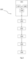
- the method for forming a protective case 100 comprises the steps of providing 101 the multilayer structure 3 and of providing 102 a mold for a battery case, not shown.
- the mold of a battery case typically used in the resin molding field provides for a male mold and a female mold.
- the method comprises the step 103 of placing the multilayer structure 2 in the female mold. It should be noted that the flexibility of the multilayer structure 3, described above, favours the adaptability of the multilayer structure to the different shapes of the female mold and the relative male mold.
- the method comprises the step 104 of closing the mold of a battery case by placing the male mold over the relative female mold and fixing them to each other by means of constraint means, not shown. In this way, the multilayer structure 3 is enclosed within the mold.
- the multilayer structure thanks to its flexibility, allows it to adapt to the different mold shapes.
- the method for forming a protective case 100 includes the step 105 of injecting resin into the mold to form the protective case for batteries 1.
- the resin matrix 2 is uniformly distributed within the mold, incorporating the multilayer structure 3 and preferably forming an external surface layer on the multilayer structure 3.
- the step of injecting resin 105 is carried out by using the method of molding with high-pressure resin transfer (HP-RTM).
- HP-RTM high-pressure resin transfer
- the use of HP-RTM technology combined with the flexible multilayer structure 3 allows the series production of the protective battery cases while maintaining the shielding properties and high structural resistance.
- the HP-RTM methodology allows a uniform distribution of the resin inside the mold allowing to incorporate the entire multilayer structure 3.
- the method for forming a protective case 100 includes the step 106 of removing the protective case 1 from the mold after curing of the injected resin. Preferably, after the insertion of the resin inside the mold, a predetermined time interval is waited for the complete polymerization of the resin 2 in which the multilayer structure 3 is embedded. In this way, the protective case for batteries 1 takes the shape defined by the mold, presenting the structural rigidity and shielding properties given by the combination of the resin matrix 2 and the multilayer structure 3.
- the step of providing 101 a multilayer structure comprises a sub-step of forming 107 the first and second reinforcement layers 4, 5 preferably by arranging a plurality of reinforcement fibers according to a predefined or random weave.
- the sub-step 107 of forming the first and second reinforcement layers 4, 5 envisages providing a fabric and/or a non-woven fabric (TNT) having characteristics of impact resistance and/or flame resistance after curing of the matrix resin 2.
- TNT non-woven fabric
- a fabric and/or a non-woven fabric (TNT) of the first and second reinforcement layers 4, 5 are flexible and adaptable to the mold.
- the step of providing 101 a multilayer structure comprises a sub-step 108 of forming the shielding layer 6 by placing metal material 7 on a polyester fabric or on a non-woven polyester fabric.
- the metal material 7 is fixed on the fabric or on the non-woven fabric by means of a polyester matrix.
- the shielding layer 6 is flexible and adaptable to the different shapes of the mold as it is made of flexible fabric or non-woven fabric. Furthermore, the flexibility of the shielding layer 6 favours the coupling with the reinforcement layers 4, 5 which are also flexible.
- the elastic and adaptability properties of the shielding layer 6 combined with the reinforcement layers 4 and 5 favour the mutual coupling of the same without mutual slippage.
- the shielding layer 6 provides a shield for the electromagnetic radiation emitted by a battery due to the presence of metal material which is disposed on the surface or inside the fabric or non-woven fabric.
- the shielding layer is made according to a co-extrusion or co-molding process.
- the step of providing 101 a multilayer structure comprises the sub-step 109 of assembling the multilayer structure 3 by placing the shielding layer 6 between the first 4 and the second reinforcement layers 5.
- the layers 4, 5, 6 overlap each other along the longitudinal direction X-X and constrained together according to a co-extrusion or co-molding process.
- the layers 4, 5, 6 are rigidly coupled to each other by means of the co-extrusion or co-molding process ensuring the correct positioning of the shielding layer 6.
- a co-extruded or co-molded multilayer structure 3 maintains the flexibility, elasticity and adaptability properties of the layers 4, 5, 6.
- the co-extrusion or co-molding process allows constraining the layers 4, 5, 6 together, avoiding mutual slippage during positioning in the mold and/or in the subsequent steps of the process and maintaining the shielding and adaptability properties of the layers.
- the production of the multilayer structure 3 through the co-extrusion or co-molding process guarantees greater uniformity in the distribution of the reinforcement material of the reinforcement layers and uniformity of the shielding of the shielding layer while maintaining the flexibility of the multilayer structure 3.
- the fabric or non-woven fabric of the shielding layer are made of reinforcement material such as for example carbon fibers and/or carbon and/or kevlar fibers.
- reinforcement material such as for example carbon fibers and/or carbon and/or kevlar fibers.
Landscapes
- Chemical & Material Sciences (AREA)
- Engineering & Computer Science (AREA)
- Chemical Kinetics & Catalysis (AREA)
- Electrochemistry (AREA)
- General Chemical & Material Sciences (AREA)
- Inorganic Chemistry (AREA)
- Composite Materials (AREA)
- Mechanical Engineering (AREA)
- Materials Engineering (AREA)
- Microelectronics & Electronic Packaging (AREA)
- Ceramic Engineering (AREA)
- Physics & Mathematics (AREA)
- Electromagnetism (AREA)
- Textile Engineering (AREA)
- Manufacturing & Machinery (AREA)
- Battery Mounting, Suspending (AREA)
- Sealing Battery Cases Or Jackets (AREA)
Description
- The present invention relates to a protective case for batteries and a method for the production of a protective case for batteries.
- It is known from the state of the art to make protective cases for batteries which at the same time provide shock protection and a shield for electromagnetic radiation emitted by the battery itself. In particular, the battery cases have a shell made of plastic material reinforced with glass fibers to provide structural integrity. The shielding properties are instead typically provided by a metal grid inserted inside the shell or by a polymeric coating containing metals applied on the external surface of the shell.
- Some examples of protective cases are described in documents
DE 202012104339 U1 ,JP 201621966 A JP 2012109452 A - Further examples of protective cases are described in the documents
KR 20180053084 A WO 2013013906 A1 in which the shielding layer has a dispersion of metal material. - In particular, the document
KR 20180053084 A - As regards document
WO 2013013906 A1 , the protective case is made by means of a production method which envisages impregnating the individual layers in a resin matrix and the subsequent stabilization in an autoclave. In particular, the layers are individually impregnated and stacked one on top of the other. Subsequently, the layers are stabilized by the combination of a heating and compression step in order to facilitate the polymerization of the resin matrix. - The cases currently used to shield batteries do not guarantee an adequate structural integrity. In fact, the metal grid and/or the shielding layer inserted inside the shell during the production step causes an uneven distribution of the plastic material forming weakening areas of the shell. This entails not only a lower impact resistance of the shell but also an ineffective shielding against electromagnetic radiation in the event that the exposed metal grid, in the weakened areas, comes into contact with a conductive material.
- Furthermore, it should be noted that the means currently used for shielding batteries do not guarantee effective shielding against electromagnetic radiation emitted by the batteries. In fact, the grid and/or the shielding layer during the production process may be subject to slippage within the mold forming areas of the shell in which a radiation shield is effectively absent. Furthermore, the polymeric coating with metal materials does not guarantee a uniform distribution of the shielding layer thus allowing the passage of radiation.
- It should be noted that the known production processes to make the protective cases can lead to an uneven distribution of the resin matrix reducing the structural integrity of the case itself in addition to the incorrect positioning of the shielding layer. In fact, during compression, the resin with which the layers are impregnated can escape partially and/or totally thus reducing the cohesion between the layers. The excess resin can also cause its accumulation between the layers causing unwanted deformities.
- Furthermore, the known methods which employ the combination of the impregnation of the layers with the compression step limit the types of possible shapes for the case in addition to the complications due to the machinery.
- The object of the invention is to provide a case for batteries capable of overcoming the above mentioned drawbacks of the prior art.
- In particular, it is an object of the present invention to provide a case capable of ensuring effective shielding against electromagnetic radiation emitted by a battery.
- A further object of the present invention is to provide a method for the production of a case for batteries which guarantees the production of cases for batteries which effectively shield electromagnetic radiation, reducing production costs.
- The specified technical task and the specified purposes are substantially achieved by a protective case for batteries and by a method for the production of a protective case for batteries comprising the technical characteristics set forth in one or more of the appended claims.
- Advantageously, the protective case allows to uniformly shield the battery from electromagnetic radiation.
- Advantageously, the protective case allows it to adapt to any shape of the mold during production.
- Advantageously, the combination of the multilayer structure and the resin matrix provide structural integrity to the case and shielding properties
- Further characteristics and advantages of the present invention will become clearer from the indicative and therefore non-limiting description of a preferred but not exclusive embodiment of a protective case for batteries and a method for the production of cases for batteries:
-
Figure 1 shows a perspective view of the protective case for batteries according to an embodiment of the present invention;
Figure 2 shows a section view of a portion of the protective case for batteries ofFigure 1 ; -
Figure 3 shows a flow diagram of the steps of the method of the present invention. - Even when not explicitly highlighted, the individual features described with reference to the specific embodiments must be considered as accessories and/or exchangeable with other features, described with reference to other embodiments.
- With reference to the appended
figures, 1 indicates a protective case for batteries according to the present invention. - This case for
batteries 1 comprises aresin matrix 2 and amultilayer structure 3 embedded in theresin matrix 2 and configured to protect a battery. Preferably, theresin matrix 2 is of the epoxy type. Preferably, themultilayer structure 3 comprises a first 4 and asecond reinforcement layer 5 configured to provide structural support to the case forbatteries 1. More preferably, themultilayer structure 3 comprises ashielding layer 6 configured to shield electromagnetic radiation emitted by a battery and disposed between the first 4 and thesecond reinforcement layers 5. - In particular, the
shielding layer 6 has a dispersion ofmetal material 7. Preferably, theshielding layer 6 has a surface and/or interstitial metallization. - Preferably, the
metal material 7 is highly conductive metal for example nickel and/or copper. - More preferably, the
shielding layer 6 comprises a polyester fabric on which themetal material 7 is dispersed. Alternatively, theshielding layer 6 can comprise a polyester non-woven fabric, known as TNT, on which themetal material 7 is dispersed. - In other words, the
shielding layer 6 defines a Faraday cage by means of the metal materials dispersed on the fabric or on the non-woven fabric so as to isolate the battery from electromagnetic wave emissions. - In particular, the
shielding layer 6, comprising the polyester fabric or non-woven fabric, has elastic properties, in order to ensure the correct positioning of the layer itself inside themultilayer structure 3 also during positioning in the mold. In fact, the use of a polyester fabric or non-woven fabric allows the adaptability of theshielding layer 6 to different mold shapes while maintaining effective shielding over the entireprotective case 1. In fact, the fabric and the non-woven polyester fabric guarantee a uniform insulation from electromagnetic waves over the entire protective case forbatteries 1. - Advantageously, the protective case for
batteries 1 can be used to shield any electromagnetic radiation emitted by an electronic device. Preferably, the protective case forbatteries 1 is used in the automotive field to prevent radiation emitted by a battery from affecting the electronics of a vehicle. - Advantageously, the dispersion of
metal material 7 on the shielding layer provides a uniform shielding effect on the whole case forbatteries 1. - Advantageously, the
shielding layer 6, thanks to its adaptability, allows reproducing the mold shapes. - It should be noted that the
layers layers - According to an embodiment, the first 4 and the
second reinforcement layers 5 comprise reinforcement materials, preferably glass fibers and/or carbon fibers. According to an alternative embodiment with respect to the previous one, the first andsecond reinforcement layers 4, 5 comprise fabrics in which glass and/or carbon fibers are inserted. - Advantageously, the first and
second reinforcement layers 4, 5 in combination with theresin matrix 2 provide structural integrity to the case forbatteries 1 following the polymerization of the resin. - Advantageously, the protective case for
batteries 1 provides the battery with protection from impacts or external agents. - Before being embedded in a resin matrix and its consolidation, the
multilayer structure 3 is flexible and adaptable to a mold for resin molding known to the skilled technician in the sector. - Preferably, the
multilayer structure 3 is made by co-extrusion or co-molding. In other words, thelayers - The
shielding layer 6, being constrained to the reinforcement layers 4, 5, avoids slipping and due to the elasticity of the polyester fabric or non-woven fabric it easily follows the deformations of the reinforcement layers 4, 5 during the assembly of themultilayer structure 3. In particular, the co-extruded or co-moldedmultilayer structure 3 maintains flexibility, strength and even and uniform shielding. - Advantageously, the flexibility of the
multilayer structure 3 simplifies the production of a case forbatteries 1 capable of shielding electromagnetic radiation as it increases the adaptability of the multilayer structure to different shapes of mold. According to an embodiment, the first reinforcement layer 4 and thesecond reinforcement layer 5 each comprise a first and asecond reinforcement sublayer first reinforcement sublayer shielding layer 6 and the respectivesecond reinforcement sublayer multilayer structure 3 overlaps, along the longitudinal direction X-X, the first andsecond reinforcement sublayer shielding layer 6 and of the first andsecond reinforcement sublayer second reinforcement layer 5. In other words, eachsecond sublayer first sublayer shielding layer 6 are positioned between thesecond sublayers - Advantageously, the use of the first and
second sublayers - The protective case for
batteries 1 comprises a base 8 and aside wall 9 which extends from the base 8 to anopening 10. In particular, the base 8 and theside wall 9 define acavity 11 inside which a battery can be placed. In detail, theside wall 9 has anedge 12 opposite the base 8 defining theopening 10. Preferably, theside wall 9 comprises aflange 13 which extends in a cantilever fashion from theedge 12 towards the outside of thecavity 11. Saidflange 13 is configured to fix the protective case for abattery 1 to a support on which a battery is fixed. - The protective case for
batteries 1 is made according to themethod 100 object of the present invention. - The method for forming a
protective case 100 comprises the steps of providing 101 themultilayer structure 3 and of providing 102 a mold for a battery case, not shown. In particular, the mold of a battery case typically used in the resin molding field provides for a male mold and a female mold. - The method comprises the
step 103 of placing themultilayer structure 2 in the female mold. It should be noted that the flexibility of themultilayer structure 3, described above, favours the adaptability of the multilayer structure to the different shapes of the female mold and the relative male mold. After placing the multilayer structure inside the female mold, the method comprises thestep 104 of closing the mold of a battery case by placing the male mold over the relative female mold and fixing them to each other by means of constraint means, not shown. In this way, themultilayer structure 3 is enclosed within the mold. - Advantageously, the
multilayer structure 3, thanks to its flexibility, allows it to adapt to the different mold shapes. - The method for forming a
protective case 100 includes thestep 105 of injecting resin into the mold to form the protective case forbatteries 1. In this way, theresin matrix 2 is uniformly distributed within the mold, incorporating themultilayer structure 3 and preferably forming an external surface layer on themultilayer structure 3. - Preferably, the step of injecting
resin 105 is carried out by using the method of molding with high-pressure resin transfer (HP-RTM). Advantageously, the use of HP-RTM technology combined with theflexible multilayer structure 3 allows the series production of the protective battery cases while maintaining the shielding properties and high structural resistance. In fact, the HP-RTM methodology allows a uniform distribution of the resin inside the mold allowing to incorporate theentire multilayer structure 3. - The method for forming a
protective case 100 includes thestep 106 of removing theprotective case 1 from the mold after curing of the injected resin. Preferably, after the insertion of the resin inside the mold, a predetermined time interval is waited for the complete polymerization of theresin 2 in which themultilayer structure 3 is embedded. In this way, the protective case forbatteries 1 takes the shape defined by the mold, presenting the structural rigidity and shielding properties given by the combination of theresin matrix 2 and themultilayer structure 3. - It should be noted that the step of providing 101 a multilayer structure comprises a sub-step of forming 107 the first and second reinforcement layers 4, 5 preferably by arranging a plurality of reinforcement fibers according to a predefined or random weave. In other words, the sub-step 107 of forming the first and second reinforcement layers 4, 5 envisages providing a fabric and/or a non-woven fabric (TNT) having characteristics of impact resistance and/or flame resistance after curing of the
matrix resin 2. However, before polymerization, a fabric and/or a non-woven fabric (TNT) of the first and second reinforcement layers 4, 5 are flexible and adaptable to the mold. - The step of providing 101 a multilayer structure comprises a sub-step 108 of forming the
shielding layer 6 by placingmetal material 7 on a polyester fabric or on a non-woven polyester fabric. Preferably, themetal material 7 is fixed on the fabric or on the non-woven fabric by means of a polyester matrix. In this way, theshielding layer 6 is flexible and adaptable to the different shapes of the mold as it is made of flexible fabric or non-woven fabric. Furthermore, the flexibility of theshielding layer 6 favours the coupling with the reinforcement layers 4, 5 which are also flexible. - In particular, the elastic and adaptability properties of the
shielding layer 6 combined with the reinforcement layers 4 and 5 favour the mutual coupling of the same without mutual slippage. - Advantageously, the
shielding layer 6 provides a shield for the electromagnetic radiation emitted by a battery due to the presence of metal material which is disposed on the surface or inside the fabric or non-woven fabric. - More preferably, the shielding layer is made according to a co-extrusion or co-molding process.
- The step of providing 101 a multilayer structure comprises the sub-step 109 of assembling the
multilayer structure 3 by placing theshielding layer 6 between the first 4 and the second reinforcement layers 5. Preferably, thelayers layers shielding layer 6. In addition, a co-extruded or co-moldedmultilayer structure 3 maintains the flexibility, elasticity and adaptability properties of thelayers layers - Advantageously, the production of the
multilayer structure 3 through the co-extrusion or co-molding process guarantees greater uniformity in the distribution of the reinforcement material of the reinforcement layers and uniformity of the shielding of the shielding layer while maintaining the flexibility of themultilayer structure 3. - According to an alternative embodiment to the previous one, the fabric or non-woven fabric of the shielding layer are made of reinforcement material such as for example carbon fibers and/or carbon and/or kevlar fibers. Advantageously, the metallization of the fabrics or non-woven fabrics with the dispersion of metal materials reduces the production costs and allows the realization of the protective case for batteries having a single flexible and adaptable layer with both shielding and structural resistance properties.
Claims (11)
- A protective case for batteries (1) of vehicles comprising:- a resin matrix (2),- a multilayer structure (3) embedded in the resin matrix (2) and configured to protect a battery, the multilayer structure (3) comprising at least one first reinforcement layer (4) and one second reinforcement layer (5),- a shielding layer (6) configured to shield the electromagnetic radiation emitted by the battery and disposed between the first (4) and second (5) reinforcement layers, the shielding layer (6) having a dispersion of metal material (7)characterized in that the shielding layer (6) comprises:- a polyester fabric with metal material (7) dispersed thereon, or- a polyester non-woven fabric with metal material (7) dispersed thereon.
- Protective case for batteries (1) as claimed in claim 1, wherein the multilayer structure (3) is co-extruded or co-molded.
- Protective case for batteries (1) as claimed in claims 1 or 2, wherein the first reinforcement layer (4) and the second reinforcement layer (5) comprise reinforcement material fibers.
- Protective case for batteries (1) as claimed in claim 3, wherein the reinforcement material fibers are glass fibers and/or carbon fibers.
- Protective case for batteries (1) as claimed in any of claims 1 to 4, wherein each of the first reinforcement layer (4) and the second reinforcement layer (5) comprises first and second reinforcement sublayers (4a, 4b, 5a, 5b), each first reinforcement sublayer (4a, 5a) being interposed between the shielding layer (6) and the respective second reinforcement sublayer (4b, 5b).
- Protective case for batteries (1) as claimed in any of claims 1 to 5, wherein the metal material (7) is nickel and/or copper.
- Protective case for batteries (1) as claimed in any of claims 1 to 6 wherein the case comprises a base (8) and a side wall (9) which extends from the base (8) to an opening (10).
- A method of forming a protective case (100) for batteries of vehicles as claimed in any of claims 1 to 7, said method comprising the steps of:- providing (101) a co-extruded or co-molded multilayer structure (3);- providing (102) a mold for a battery case;- placing (103) the multilayer structure (3) in the mold;- injecting (105) resin into the mold to form the protective case (1),- removing (106) the protective case (1) from the mold after curing of the injected resin.
- Method of forming a protective case (100) for vehicle batteries as claimed in claim 8 wherein the step of providing (103) the multilayer structure (3) comprises the sub-steps of- forming (107) a first reinforcement layer (4) and a second reinforcement layer (5);- forming (108) a shielding layer (6) by depositing metal material (7) on a polyester fabric or on a polyester non-woven fabric;- assembling (109) the multilayer structure (3) by placing the shielding layer (6) between the first (4) and the second (5) reinforcement layers.
- Method of forming a protective case (100) for vehicle batteries as claimed in claim 9, wherein the step of assembling (109) the multilayer structure (3) is carried out using a co-extrusion or co-molding process.
- Method of forming a protective case (1) for vehicle batteries as claimed in any of claims 8 to 10, wherein the step of injecting the resin (105) is carried out by High-Pressure Resin Transfer Molding (HP-RTM).
Applications Claiming Priority (1)
| Application Number | Priority Date | Filing Date | Title |
|---|---|---|---|
| IT201900003191 | 2019-03-05 |
Publications (3)
| Publication Number | Publication Date |
|---|---|
| EP3706193A1 EP3706193A1 (en) | 2020-09-09 |
| EP3706193C0 EP3706193C0 (en) | 2023-06-14 |
| EP3706193B1 true EP3706193B1 (en) | 2023-06-14 |
Family
ID=67262818
Family Applications (1)
| Application Number | Title | Priority Date | Filing Date |
|---|---|---|---|
| EP20159756.4A Active EP3706193B1 (en) | 2019-03-05 | 2020-02-27 | Protective case for batteries and method for the production of a protective case for batteries |
Country Status (2)
| Country | Link |
|---|---|
| EP (1) | EP3706193B1 (en) |
| CN (1) | CN111376552A (en) |
Families Citing this family (6)
| Publication number | Priority date | Publication date | Assignee | Title |
|---|---|---|---|---|
| CN111907092A (en) * | 2020-07-22 | 2020-11-10 | 杭州卡涞复合材料科技有限公司 | RTM (resin transfer molding) method for sandwich structure of automobile composite material battery box |
| CN113809452A (en) * | 2021-08-26 | 2021-12-17 | 南通强生石墨烯科技有限公司 | Electric vehicle battery pack protection shell and preparation method thereof |
| DE102021123003A1 (en) * | 2021-09-06 | 2023-03-09 | Kautex Textron Gmbh & Co. Kg | Battery tray made of plastic, having an insert, tool and method for producing a battery tray, traction battery and motor vehicle |
| WO2023129771A1 (en) * | 2021-12-29 | 2023-07-06 | Bridgestone Americas, Inc. | Structural composites with electromagnetic compatibility for battery enclosures |
| WO2024088620A1 (en) * | 2022-10-27 | 2024-05-02 | Webasto SE | Electric heating device for a vehicle |
| DE102023111776A1 (en) * | 2023-05-05 | 2024-11-07 | Elringklinger Ag | Protective element, method for its production, energy storage device and motor vehicle |
Family Cites Families (11)
| Publication number | Priority date | Publication date | Assignee | Title |
|---|---|---|---|---|
| CN101531804B (en) * | 2009-04-13 | 2010-12-29 | 天津大学 | Electromagnetic shielding compound material made from three-dimensional braided nickel-plated carbon fiber and epoxy resin and method for preparing same |
| JP6003010B2 (en) | 2010-11-18 | 2016-10-05 | 三菱レイヨン株式会社 | Electromagnetic wave shielding composite material, electronic equipment casing and battery case |
| KR20120088496A (en) * | 2011-01-31 | 2012-08-08 | 이와오 히시다 | Casing for electronic device, method for manufacturing same, and electronic device |
| ITMI20111417A1 (en) | 2011-07-28 | 2013-01-29 | Lamiflex Spa | COATING ELEMENT FOR THE CREATION OF SHIELDS AGAINST ELECTROMAGNETIC RADIATIONS. |
| JP6252044B2 (en) * | 2012-10-02 | 2017-12-27 | 住友ベークライト株式会社 | Laminate |
| DE202012104339U1 (en) | 2012-11-12 | 2014-02-14 | Rehau Ag + Co | Battery housing part and battery housing for a traction battery of an electric vehicle |
| CN103552318B (en) * | 2013-11-05 | 2016-03-16 | 中航复合材料有限责任公司 | A kind of non-woven fabrics of containing metal coating and goods thereof |
| JP6226298B2 (en) | 2014-07-24 | 2017-11-08 | ヤンマー株式会社 | Combine |
| JP2016219466A (en) * | 2015-05-14 | 2016-12-22 | トヨタ紡織株式会社 | Electromagnetic wave shield material |
| WO2017039032A1 (en) * | 2015-09-02 | 2017-03-09 | 윈엔윈(주) | Electromagnetic wave shielding material sheet and manufacturing method therefor |
| KR101913209B1 (en) | 2016-11-11 | 2018-12-28 | 한화큐셀앤드첨단소재 주식회사 | Electromagnetic wave shield material lamination structure and manufacturing method of the same |
-
2020
- 2020-02-27 EP EP20159756.4A patent/EP3706193B1/en active Active
- 2020-03-03 CN CN202010141584.XA patent/CN111376552A/en active Pending
Also Published As
| Publication number | Publication date |
|---|---|
| CN111376552A (en) | 2020-07-07 |
| EP3706193A1 (en) | 2020-09-09 |
| EP3706193C0 (en) | 2023-06-14 |
Similar Documents
| Publication | Publication Date | Title |
|---|---|---|
| EP3706193A1 (en) | Protective case for batteries and method for the production of a protective case for batteries | |
| US7692096B2 (en) | Electromagnetically shielded cable | |
| US20090315663A1 (en) | Reactor core and reactor | |
| US9661792B2 (en) | Protector and wire harness | |
| US8380028B2 (en) | Composite cable | |
| EP2591911A1 (en) | A method for the automated manufacture of a fibre composite component with integrated lightning protection, and also a fibre composite component | |
| KR20150121322A (en) | Battery case for vehicle | |
| US20150014052A1 (en) | Wire harness and method for manufacturing wire harness | |
| US9466404B2 (en) | Rigid/pliable sectional resin infused shielded wire harness | |
| US9985423B2 (en) | Wire harness and method for producing wire harness | |
| US9349509B2 (en) | Wire harness and manufacturing method for wire harness | |
| US20010018979A1 (en) | Device and method of forming a unitary electrically shielded panel | |
| US20190070803A1 (en) | Improved Method For Manufacturing A Structural Component Of A Motor Vehicle | |
| JP2008226587A (en) | Manufacturing method of automotive wiring harness and automotive wiring harness | |
| EP2626814A1 (en) | Transponder comprising means for reducing bending stress on the antenna | |
| US11718424B2 (en) | Spacecraft and spacecraft protective blankets | |
| CN107836028B (en) | Coil unit for inductive energy transmission | |
| US20200406803A1 (en) | Floor carpet with electromagnetic shielding | |
| WO2012111704A1 (en) | Carbon-fiber-reinforced plastic structure and method for producing same | |
| JP2013023184A (en) | Outer panel for transportation apparatus and method of manufacturing the same | |
| EP2000276B1 (en) | Polymer components and a method of curing | |
| KR102936141B1 (en) | Manufacturing method for electromagnetic wave shield material and electromagnetic wave shield material manufactured thereby | |
| US20210162907A1 (en) | Floor carpet with electromagnetic shielding and improved acoustic dampening | |
| WO2013013906A1 (en) | Cladding element for providing shielding against electromagnetic radiation | |
| US20250118842A1 (en) | Battery enclosure including multi-functional, multi-layered thermoplastic composite laminated structure |
Legal Events
| Date | Code | Title | Description |
|---|---|---|---|
| PUAI | Public reference made under article 153(3) epc to a published international application that has entered the european phase |
Free format text: ORIGINAL CODE: 0009012 |
|
| STAA | Information on the status of an ep patent application or granted ep patent |
Free format text: STATUS: THE APPLICATION HAS BEEN PUBLISHED |
|
| AK | Designated contracting states |
Kind code of ref document: A1 Designated state(s): AL AT BE BG CH CY CZ DE DK EE ES FI FR GB GR HR HU IE IS IT LI LT LU LV MC MK MT NL NO PL PT RO RS SE SI SK SM TR |
|
| AX | Request for extension of the european patent |
Extension state: BA ME |
|
| STAA | Information on the status of an ep patent application or granted ep patent |
Free format text: STATUS: REQUEST FOR EXAMINATION WAS MADE |
|
| 17P | Request for examination filed |
Effective date: 20210308 |
|
| RBV | Designated contracting states (corrected) |
Designated state(s): AL AT BE BG CH CY CZ DE DK EE ES FI FR GB GR HR HU IE IS IT LI LT LU LV MC MK MT NL NO PL PT RO RS SE SI SK SM TR |
|
| REG | Reference to a national code |
Ref country code: DE Ref legal event code: R079 Ref document number: 602020012404 Country of ref document: DE Free format text: PREVIOUS MAIN CLASS: H01M0002100000 Ipc: B29C0070080000 |
|
| GRAP | Despatch of communication of intention to grant a patent |
Free format text: ORIGINAL CODE: EPIDOSNIGR1 |
|
| STAA | Information on the status of an ep patent application or granted ep patent |
Free format text: STATUS: GRANT OF PATENT IS INTENDED |
|
| RIC1 | Information provided on ipc code assigned before grant |
Ipc: H01M 50/24 20210101ALI20221215BHEP Ipc: H01M 50/231 20210101ALI20221215BHEP Ipc: H01M 50/229 20210101ALI20221215BHEP Ipc: H01M 50/227 20210101ALI20221215BHEP Ipc: H01M 50/224 20210101ALI20221215BHEP Ipc: H01M 50/222 20210101ALI20221215BHEP Ipc: H05K 9/00 20060101ALI20221215BHEP Ipc: B29C 70/88 20060101ALI20221215BHEP Ipc: B29C 70/84 20060101ALI20221215BHEP Ipc: B29C 70/48 20060101ALI20221215BHEP Ipc: B29C 70/08 20060101AFI20221215BHEP |
|
| INTG | Intention to grant announced |
Effective date: 20230105 |
|
| GRAS | Grant fee paid |
Free format text: ORIGINAL CODE: EPIDOSNIGR3 |
|
| GRAA | (expected) grant |
Free format text: ORIGINAL CODE: 0009210 |
|
| STAA | Information on the status of an ep patent application or granted ep patent |
Free format text: STATUS: THE PATENT HAS BEEN GRANTED |
|
| AK | Designated contracting states |
Kind code of ref document: B1 Designated state(s): AL AT BE BG CH CY CZ DE DK EE ES FI FR GB GR HR HU IE IS IT LI LT LU LV MC MK MT NL NO PL PT RO RS SE SI SK SM TR |
|
| REG | Reference to a national code |
Ref country code: CH Ref legal event code: EP |
|
| REG | Reference to a national code |
Ref country code: DE Ref legal event code: R096 Ref document number: 602020012404 Country of ref document: DE |
|
| REG | Reference to a national code |
Ref country code: AT Ref legal event code: REF Ref document number: 1578930 Country of ref document: AT Kind code of ref document: T Effective date: 20230715 |
|
| U01 | Request for unitary effect filed |
Effective date: 20230711 |
|
| U07 | Unitary effect registered |
Designated state(s): AT BE BG DE DK EE FI FR IT LT LU LV MT NL PT SE SI Effective date: 20230724 |
|
| REG | Reference to a national code |
Ref country code: LT Ref legal event code: MG9D |
|
| PG25 | Lapsed in a contracting state [announced via postgrant information from national office to epo] |
Ref country code: NO Free format text: LAPSE BECAUSE OF FAILURE TO SUBMIT A TRANSLATION OF THE DESCRIPTION OR TO PAY THE FEE WITHIN THE PRESCRIBED TIME-LIMIT Effective date: 20230914 Ref country code: ES Free format text: LAPSE BECAUSE OF FAILURE TO SUBMIT A TRANSLATION OF THE DESCRIPTION OR TO PAY THE FEE WITHIN THE PRESCRIBED TIME-LIMIT Effective date: 20230614 |
|
| PG25 | Lapsed in a contracting state [announced via postgrant information from national office to epo] |
Ref country code: RS Free format text: LAPSE BECAUSE OF FAILURE TO SUBMIT A TRANSLATION OF THE DESCRIPTION OR TO PAY THE FEE WITHIN THE PRESCRIBED TIME-LIMIT Effective date: 20230614 Ref country code: HR Free format text: LAPSE BECAUSE OF FAILURE TO SUBMIT A TRANSLATION OF THE DESCRIPTION OR TO PAY THE FEE WITHIN THE PRESCRIBED TIME-LIMIT Effective date: 20230614 Ref country code: GR Free format text: LAPSE BECAUSE OF FAILURE TO SUBMIT A TRANSLATION OF THE DESCRIPTION OR TO PAY THE FEE WITHIN THE PRESCRIBED TIME-LIMIT Effective date: 20230915 |
|
| PG25 | Lapsed in a contracting state [announced via postgrant information from national office to epo] |
Ref country code: SK Free format text: LAPSE BECAUSE OF FAILURE TO SUBMIT A TRANSLATION OF THE DESCRIPTION OR TO PAY THE FEE WITHIN THE PRESCRIBED TIME-LIMIT Effective date: 20230614 |
|
| PG25 | Lapsed in a contracting state [announced via postgrant information from national office to epo] |
Ref country code: IS Free format text: LAPSE BECAUSE OF FAILURE TO SUBMIT A TRANSLATION OF THE DESCRIPTION OR TO PAY THE FEE WITHIN THE PRESCRIBED TIME-LIMIT Effective date: 20231014 |
|
| PG25 | Lapsed in a contracting state [announced via postgrant information from national office to epo] |
Ref country code: SM Free format text: LAPSE BECAUSE OF FAILURE TO SUBMIT A TRANSLATION OF THE DESCRIPTION OR TO PAY THE FEE WITHIN THE PRESCRIBED TIME-LIMIT Effective date: 20230614 Ref country code: SK Free format text: LAPSE BECAUSE OF FAILURE TO SUBMIT A TRANSLATION OF THE DESCRIPTION OR TO PAY THE FEE WITHIN THE PRESCRIBED TIME-LIMIT Effective date: 20230614 Ref country code: RO Free format text: LAPSE BECAUSE OF FAILURE TO SUBMIT A TRANSLATION OF THE DESCRIPTION OR TO PAY THE FEE WITHIN THE PRESCRIBED TIME-LIMIT Effective date: 20230614 Ref country code: IS Free format text: LAPSE BECAUSE OF FAILURE TO SUBMIT A TRANSLATION OF THE DESCRIPTION OR TO PAY THE FEE WITHIN THE PRESCRIBED TIME-LIMIT Effective date: 20231014 Ref country code: CZ Free format text: LAPSE BECAUSE OF FAILURE TO SUBMIT A TRANSLATION OF THE DESCRIPTION OR TO PAY THE FEE WITHIN THE PRESCRIBED TIME-LIMIT Effective date: 20230614 |
|
| PG25 | Lapsed in a contracting state [announced via postgrant information from national office to epo] |
Ref country code: PL Free format text: LAPSE BECAUSE OF FAILURE TO SUBMIT A TRANSLATION OF THE DESCRIPTION OR TO PAY THE FEE WITHIN THE PRESCRIBED TIME-LIMIT Effective date: 20230614 |
|
| REG | Reference to a national code |
Ref country code: DE Ref legal event code: R097 Ref document number: 602020012404 Country of ref document: DE |
|
| U20 | Renewal fee for the european patent with unitary effect paid |
Year of fee payment: 5 Effective date: 20240227 |
|
| PLBE | No opposition filed within time limit |
Free format text: ORIGINAL CODE: 0009261 |
|
| STAA | Information on the status of an ep patent application or granted ep patent |
Free format text: STATUS: NO OPPOSITION FILED WITHIN TIME LIMIT |
|
| 26N | No opposition filed |
Effective date: 20240315 |
|
| PG25 | Lapsed in a contracting state [announced via postgrant information from national office to epo] |
Ref country code: MC Free format text: LAPSE BECAUSE OF FAILURE TO SUBMIT A TRANSLATION OF THE DESCRIPTION OR TO PAY THE FEE WITHIN THE PRESCRIBED TIME-LIMIT Effective date: 20230614 |
|
| REG | Reference to a national code |
Ref country code: CH Ref legal event code: PL |
|
| PG25 | Lapsed in a contracting state [announced via postgrant information from national office to epo] |
Ref country code: CH Free format text: LAPSE BECAUSE OF NON-PAYMENT OF DUE FEES Effective date: 20240229 |
|
| GBPC | Gb: european patent ceased through non-payment of renewal fee |
Effective date: 20240227 |
|
| PG25 | Lapsed in a contracting state [announced via postgrant information from national office to epo] |
Ref country code: CH Free format text: LAPSE BECAUSE OF NON-PAYMENT OF DUE FEES Effective date: 20240229 |
|
| PG25 | Lapsed in a contracting state [announced via postgrant information from national office to epo] |
Ref country code: GB Free format text: LAPSE BECAUSE OF NON-PAYMENT OF DUE FEES Effective date: 20240227 |
|
| PG25 | Lapsed in a contracting state [announced via postgrant information from national office to epo] |
Ref country code: IE Free format text: LAPSE BECAUSE OF NON-PAYMENT OF DUE FEES Effective date: 20240227 |
|
| PG25 | Lapsed in a contracting state [announced via postgrant information from national office to epo] |
Ref country code: IE Free format text: LAPSE BECAUSE OF NON-PAYMENT OF DUE FEES Effective date: 20240227 Ref country code: GB Free format text: LAPSE BECAUSE OF NON-PAYMENT OF DUE FEES Effective date: 20240227 |
|
| U20 | Renewal fee for the european patent with unitary effect paid |
Year of fee payment: 6 Effective date: 20250219 |
|
| PG25 | Lapsed in a contracting state [announced via postgrant information from national office to epo] |
Ref country code: CY Free format text: LAPSE BECAUSE OF FAILURE TO SUBMIT A TRANSLATION OF THE DESCRIPTION OR TO PAY THE FEE WITHIN THE PRESCRIBED TIME-LIMIT; INVALID AB INITIO Effective date: 20200227 |
|
| PG25 | Lapsed in a contracting state [announced via postgrant information from national office to epo] |
Ref country code: HU Free format text: LAPSE BECAUSE OF FAILURE TO SUBMIT A TRANSLATION OF THE DESCRIPTION OR TO PAY THE FEE WITHIN THE PRESCRIBED TIME-LIMIT; INVALID AB INITIO Effective date: 20200227 |
|
| PG25 | Lapsed in a contracting state [announced via postgrant information from national office to epo] |
Ref country code: TR Free format text: LAPSE BECAUSE OF FAILURE TO SUBMIT A TRANSLATION OF THE DESCRIPTION OR TO PAY THE FEE WITHIN THE PRESCRIBED TIME-LIMIT Effective date: 20230614 |
|
| U20 | Renewal fee for the european patent with unitary effect paid |
Year of fee payment: 7 Effective date: 20260226 |