EP3705919A1 - Optical connector and method for connecting optical connector - Google Patents
Optical connector and method for connecting optical connector Download PDFInfo
- Publication number
- EP3705919A1 EP3705919A1 EP18883864.3A EP18883864A EP3705919A1 EP 3705919 A1 EP3705919 A1 EP 3705919A1 EP 18883864 A EP18883864 A EP 18883864A EP 3705919 A1 EP3705919 A1 EP 3705919A1
- Authority
- EP
- European Patent Office
- Prior art keywords
- ferrule
- housing
- optical connector
- face
- upward force
- Prior art date
- Legal status (The legal status is an assumption and is not a legal conclusion. Google has not performed a legal analysis and makes no representation as to the accuracy of the status listed.)
- Withdrawn
Links
- 230000003287 optical effect Effects 0.000 title claims abstract description 101
- 238000000034 method Methods 0.000 title claims description 10
- 239000000835 fiber Substances 0.000 claims abstract description 16
- 230000008878 coupling Effects 0.000 claims description 64
- 238000010168 coupling process Methods 0.000 claims description 64
- 238000005859 coupling reaction Methods 0.000 claims description 64
- 239000013307 optical fiber Substances 0.000 abstract description 26
- 230000003466 anti-cipated effect Effects 0.000 abstract description 23
- 238000010586 diagram Methods 0.000 description 23
- 210000000078 claw Anatomy 0.000 description 19
- 238000006073 displacement reaction Methods 0.000 description 8
- 238000005299 abrasion Methods 0.000 description 4
- 230000005489 elastic deformation Effects 0.000 description 2
- 230000008602 contraction Effects 0.000 description 1
- 230000000694 effects Effects 0.000 description 1
- 238000005498 polishing Methods 0.000 description 1
- 230000000717 retained effect Effects 0.000 description 1
Images






Classifications
-
- G—PHYSICS
- G02—OPTICS
- G02B—OPTICAL ELEMENTS, SYSTEMS OR APPARATUS
- G02B6/00—Light guides; Structural details of arrangements comprising light guides and other optical elements, e.g. couplings
- G02B6/24—Coupling light guides
- G02B6/36—Mechanical coupling means
- G02B6/38—Mechanical coupling means having fibre to fibre mating means
- G02B6/3807—Dismountable connectors, i.e. comprising plugs
- G02B6/3873—Connectors using guide surfaces for aligning ferrule ends, e.g. tubes, sleeves, V-grooves, rods, pins, balls
- G02B6/3882—Connectors using guide surfaces for aligning ferrule ends, e.g. tubes, sleeves, V-grooves, rods, pins, balls using rods, pins or balls to align a pair of ferrule ends
-
- G—PHYSICS
- G02—OPTICS
- G02B—OPTICAL ELEMENTS, SYSTEMS OR APPARATUS
- G02B6/00—Light guides; Structural details of arrangements comprising light guides and other optical elements, e.g. couplings
- G02B6/24—Coupling light guides
- G02B6/36—Mechanical coupling means
- G02B6/38—Mechanical coupling means having fibre to fibre mating means
- G02B6/3807—Dismountable connectors, i.e. comprising plugs
- G02B6/381—Dismountable connectors, i.e. comprising plugs of the ferrule type, e.g. fibre ends embedded in ferrules, connecting a pair of fibres
- G02B6/3818—Dismountable connectors, i.e. comprising plugs of the ferrule type, e.g. fibre ends embedded in ferrules, connecting a pair of fibres of a low-reflection-loss type
- G02B6/3822—Dismountable connectors, i.e. comprising plugs of the ferrule type, e.g. fibre ends embedded in ferrules, connecting a pair of fibres of a low-reflection-loss type with beveled fibre ends
-
- G—PHYSICS
- G02—OPTICS
- G02B—OPTICAL ELEMENTS, SYSTEMS OR APPARATUS
- G02B6/00—Light guides; Structural details of arrangements comprising light guides and other optical elements, e.g. couplings
- G02B6/24—Coupling light guides
- G02B6/36—Mechanical coupling means
- G02B6/38—Mechanical coupling means having fibre to fibre mating means
- G02B6/3807—Dismountable connectors, i.e. comprising plugs
- G02B6/3869—Mounting ferrules to connector body, i.e. plugs
-
- G—PHYSICS
- G02—OPTICS
- G02B—OPTICAL ELEMENTS, SYSTEMS OR APPARATUS
- G02B6/00—Light guides; Structural details of arrangements comprising light guides and other optical elements, e.g. couplings
- G02B6/24—Coupling light guides
- G02B6/36—Mechanical coupling means
- G02B6/38—Mechanical coupling means having fibre to fibre mating means
- G02B6/3807—Dismountable connectors, i.e. comprising plugs
- G02B6/3873—Connectors using guide surfaces for aligning ferrule ends, e.g. tubes, sleeves, V-grooves, rods, pins, balls
- G02B6/3885—Multicore or multichannel optical connectors, i.e. one single ferrule containing more than one fibre, e.g. ribbon type
Definitions
- the present invention relates to an optical connector and a method for connecting an optical connector.
- Patent Literature 1 describes that, when respective connecting end faces of such obliquely-polished ferrules are butted against one another, axial misalignment occurs between optical fibers as a result of the ferrules getting vertically displaced due to the clearance between each ferrule's guide pin hole and a positioning guide pin.
- Patent Literature 1 describes setting the position, in the up/down (vertical) direction, of optical fiber holes at a position slightly deviated from the guide pin hole's central axis by anticipating beforehand the amount of vertical displacement that the ferrules undergo.
- Patent Literature 1 JP 2005-181832A
- the optical fiber holes of the aforementioned ferrule are provided at a position that takes into account beforehand the amount of vertical displacement of the ferrule; thus, if the ferrules do not get vertically displaced by the previously anticipated amount, connection loss between optical fibers will increase. Also, if the amount of vertical displacement of the ferrules varies every time the optical connector is connected/disconnected, variations will occur in the connection loss between optical fibers, thereby making it difficult to stably achieve low loss.
- An objective of the present invention is to stably achieve low loss.
- a primary aspect of the invention for achieving the aforementioned objective is an optical connector that includes: a ferrule including a guide pin hole, a plurality of fiber holes lined up in a width direction, and an inclined end face; a housing that houses the ferrule in a recedably pressed manner; and an application part that is configured to apply an upward force to the ferrule when connecting the optical connector with a counterpart connector, wherein a direction that is orthogonal to a connector connecting/disconnecting direction and to the width direction is defined as "up/down direction", and a side of the inclined end face that projects toward the counterpart connector is defined as "up”.
- the present invention can stably achieve low loss.
- an optical connector that includes: a ferrule including a guide pin hole, a plurality of fiber holes lined up in a width direction, and an inclined end face; a housing that houses the ferrule in a recedably pressed manner; and an application part that is configured to apply an upward force to the ferrule when connecting the optical connector with a counterpart connector, wherein a direction that is orthogonal to a connector connecting/disconnecting direction and to the width direction is defined as "up/down direction", and a side of the inclined end face that projects toward the counterpart connector is defined as "up”.
- the application part applies an upward force to the ferrule after fitting together a guide pin and a guide pin hole when connecting the optical connector with the counterpart connector.
- damage to the inclined end face of the ferrule can be suppressed.
- the application part applies an upward force to the ferrule before said inclined end face of said ferrule comes into contact with an inclined end face of a ferrule of the counterpart connector.
- an upward force can be applied to the ferrule before friction force acts on the inclined end face of the ferrule.
- the application part releases the force applied to the ferrule after applying the upward force to the ferrule.
- the durability of the optical connector is improved.
- the application part releases the force applied to the ferrule after said inclined end face of said ferrule comes into contact with an inclined end face of a ferrule of the counterpart connector.
- the application part releases the force applied to the ferrule after said inclined end face of said ferrule comes into contact with an inclined end face of a ferrule of the counterpart connector.
- the application part applies an upward force to the ferrule by contacting a body part of the ferrule.
- force can be applied to a section close to the inclined end face, and thus, the end face of an optical fiber can be displaced upward by an amount anticipated beforehand.
- the application part may apply an upward force to the ferrule by contacting a collar part of the ferrule.
- the application part may apply an upward force to the ferrule by applying force to a member arranged on a rear side of the ferrule.
- a coupling is mounted to the housing; and the application part applies an upward force to the ferrule in conjunction with movement of the coupling with respect to the housing. Because the amount of movement of the coupling at the time of connecting the connector is relatively large, it is easier to apply a large force and displacement to the ferrule compared to a configuration where force is applied to the ferrule in conjunction with the movement of the ferrule.
- the application part includes a pressing part provided to the coupling; and when the coupling recedes with respect to the housing, the pressing part presses the ferrule upward by moving upward while receding along a guide face provided to the housing.
- a pressing part provided to the coupling; and when the coupling recedes with respect to the housing, the pressing part presses the ferrule upward by moving upward while receding along a guide face provided to the housing.
- an upward force can be applied to the ferrule by pressing.
- the application part includes a pressing part provided to the housing; and when the coupling recedes with respect to the housing, the pressing part presses the ferrule upward by receiving force from the coupling.
- a pressing part provided to the housing; and when the coupling recedes with respect to the housing, the pressing part presses the ferrule upward by receiving force from the coupling.
- an upward force can be applied to the ferrule in conjunction with the movement of the coupling with respect to the housing, even in cases where the pressing part is not provided to the coupling.
- the pressing part is provided on an opposite side from a side of the housing where a key is provided.
- the pressing part can be arranged without being constrained by the arrangement of the key.
- the application part applies an upward force to the ferrule in conjunction with movement of the ferrule with respect to the housing.
- an upward force can be applied to the ferrule without being in conjunction with the movement of the coupling.
- the application part includes a protrusion that moves together with the ferrule, and a contact part provided to the housing; and when the ferrule recedes with respect to the housing, the ferrule receives an upward force from the protrusion due to the protrusion coming into contact with the contact part.
- an upward force can be applied to the ferrule in conjunction with the movement of the ferrule with a simple configuration.
- the upward force to the ferrule is released due to the protrusion moving over the contact part.
- the durability of the optical connector is improved.
- a depression is formed in a lower surface of the ferrule; and the protrusion is provided in the depression so as not to protrude below the lower surface of the ferrule.
- the lower surface of the ferrule can easily be used as a reference surface.
- the application part is a spring that presses the ferrule frontward with respect to the housing; and a seat part at a rear end of the spring is inclined with respect to a plane perpendicular to an axial direction of the spring.
- an upward force can be applied to the ferrule with a simple configuration.
- Also disclosed is a method for connecting an optical connector that includes: a ferrule including a guide pin hole, a plurality of fiber holes lined up in a width direction, and an inclined end face; and a housing that houses the ferrule in a recedably pressed manner, the method involving: applying an upward force to the ferrule when connecting the optical connector with a counterpart connector, wherein a direction that is orthogonal to a connector connecting/disconnecting direction and to the width direction is defined as "up/down direction", and a side of the inclined end face that projects toward the counterpart connector is defined as "up”.
- this optical connector connecting method low loss can be achieved stably.
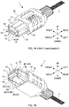
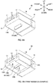
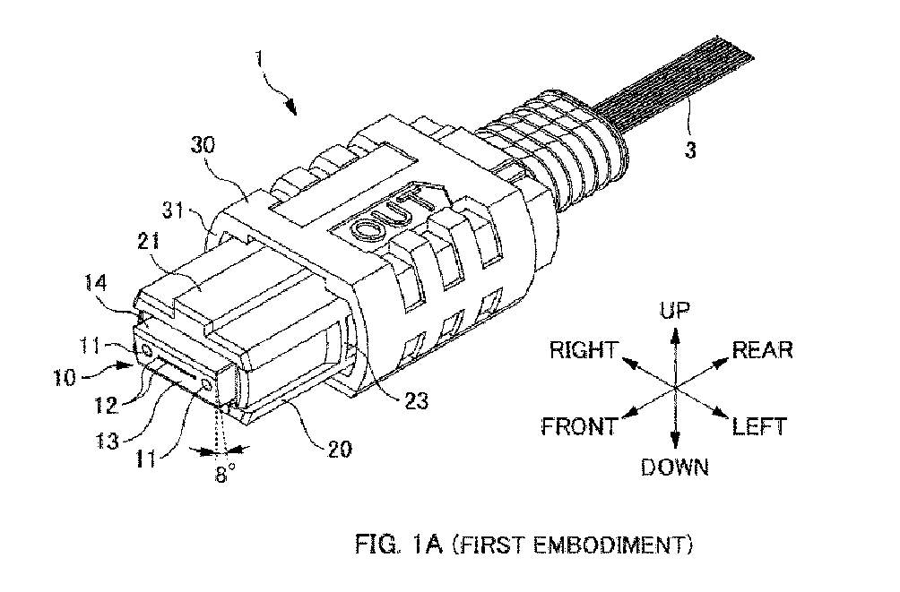
- Figs. 1A and 1B are perspective views of an optical connector 1 according to a first embodiment.
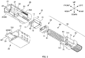
- Fig. 2 is an exploded perspective view of the optical connector 1 of the first embodiment.
- the connecting/disconnecting direction (attaching/detaching direction) of the optical connector 1 is defined as “front/rear direction", wherein the side toward a counterpart connector (not illustrated) is defined as “front”, and the opposite side is defined as “rear”.
- the direction in which a pair of guide pin holes 11 is lined up and in which a plurality of optical fiber holes 12 are lined up is defined as “left/right direction”, wherein the right-hand side when viewed from the rear toward the front is defined as “right”, and the opposite side is defined as "left”.
- the left/right direction is also referred to as "width direction”.
- the direction orthogonal to the "front/rear direction” and the "left/right direction (width direction)” is defined as “up/down direction", wherein the side of an inclined end face 13 of a ferrule 10 that projects toward the front side (toward a counterpart connector) is defined as “up”, and the opposite side is defined as “down”.
- the optical connector 1's side where a key 21 is provided is "up”.
- the optical connector 1 is a multifiber push-on (MPO) optical connector compliant with, for example, JIS C5982 or IEC 61754-7.
- the optical connector 1 includes a ferrule 10 and a housing 20.
- the ferrule 10 is a member that retains an end portion of optical fibers 3.
- the ferrule 10 includes guide pin holes 11, a plurality of fiber holes 12, and an inclined end face 13.
- the ferrule 10 also includes a body part 14 and a collar part 15.
- the collar part 15 is a section located more toward the rear side than the body part 14 and is a section that projects more outward than the body part 14.
- Each guide pin hole 11 is a hole in which a guide pin 111 is to be inserted.
- a guide pin 111 is inserted in advance in each guide pin hole 11 such that an end portion of the guide pin 111 projects from the guide pin hole 11.
- a guide pin 111 of a counterpart connector will be inserted into the guide pin hole 11.
- Positioning between ferrules 10 is achieved by fitting respective guide pins 111 into the guide pin holes 11 at the time of connecting the connectors.
- the guide pin hole 11 thus serves as a section constituting a positioning part together with the guide pin 111.
- the fiber holes 12 are holes in which end portions of respective optical fibers 3 are to be inserted. An end portion of an optical fiber 3 is fixed in each fiber hole 12.
- the optical fiber 3 inserted in each fiber hole 12 is a single-mode optical fiber, but it may be a multi-mode optical fiber.
- the inclined end face 13 is a connecting end face that is to be connected with a ferrule of a counterpart connector.
- the inclined end face 13 is inclined by about 8 degrees with respect to a plane perpendicular to the optical axis of the optical fibers 3.
- the inclined end face 13 is formed by being obliquely polished together with the respective end faces of the optical fibers 3 inserted in the respective fiber holes 12. Inclining the end face of the optical fiber 3 reduces the light reflection amount at the connection point.
- the housing 20 is a cylindrical member that houses the ferrule 10 in a recedably pressed manner.
- An inwardly-projecting projection 22 is provided on the inner wall surface of the housing 20. The projection 22 comes into contact with the collar part 15 of the ferrule 10, and thereby, the ferrule 10, which is being pressed frontward, is prevented from falling out toward the front. Engagement parts 23 onto which claws 91 (described later) of an adapter 90 are latched are formed in the respective side surfaces of the housing 20.
- a coupling 30 is arranged outside the housing 20.
- the coupling 30 is a joining member that retains a state (latched state) in which claws 91 (described later) of an adapter 90 are caught by the engagement parts 23 of the housing 20.
- the coupling 30 is provided so as to be slidable in the front/rear direction with respect to the housing 20.
- Springs 20A are arranged between the coupling 30 and the housing 20, and the springs 20A recedably press the coupling 30 frontward with respect to the housing 20.
- the inner wall surface of the coupling 30 prevents the claws 91 of the adapter 90 from opening outward, thereby retaining the latched state.
- the coupling 30 is slid rearward with respect to the housing 20, and this allows the claws 91 of the adapter 90 to open outward, thereby releasing the latched state.
- the housing 20 also houses a floating mechanism 40 that presses the ferrule 10 frontward.
- Fig. 2 illustrates a floating mechanism 40 housed in the housing 20.
- the floating mechanism 40 is a mechanism that presses the ferrule 10 frontward.
- the floating mechanism 40 includes a pin clamp 50, a spring 60, and a spring push member 70.
- the pin clamp 50 is a member arranged on the rear side of the ferrule 10. In cases where the optical connector 1 is a male-type connector, the pin clamp 50 retains the respective rear ends of the guide pins 111. In this case, the guide pins 111 will penetrate the respective guide pin holes 11 in the ferrule 10, and the respective tip ends of the guide pins 111 will project out from the inclined end face 13.
- a front end portion of the spring 60 is fixed to the rear portion of the pin clamp 50.
- the spring 60 is an elastic member that applies pressing force for pressing the ferrule 10 frontward.
- the spring 60 is housed in the housing 20 in a compressed and deformed state between the pin clamp 50 and the spring push member 70.
- the front end portion of the spring 60 is fixed to the pin clamp 50, and the rear end portion of the spring 60 is fixed to the spring push member 70.
- the spring push member 70 is a member that allows the spring 60 to be housed in the housing 20 in a compressed state.
- the spring push member 70 includes a pair of arms 71.
- the spring 60 is housed in a space between the pair of arms 71.
- a lug 711 is formed outwardly. By making the lug 711 engage with a window 24 formed in the side surface of the housing 20, the spring 60 is housed inside the housing 20 in a compressed state.
- the ferrule 10 is pressed frontward via the pin clamp 50 by the opposing force of the compressed-and-deformed spring 60.
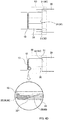
- Figs. 3A and 3B are explanatory diagrams illustrating axial misalignment between ferrules 10.
- the ferrule 10 As described above, positioning between ferrules 10 is achieved by fitting respective guide pins 111 into the guide pin holes 11 at the time of connecting the connectors. Note, however, that the diameter of the guide pin hole 11 is formed larger than the diameter of the guide pin 111, and thus, there is a clearance (gap) between the guide pin hole 11 and the guide pin 111. Meanwhile, the ferrule 10 has an inclined end face 13, and at the time of connecting the connectors, the respective inclined end faces 13 of the ferrules 10 butt against one another in a frontwardly-pressed state. As a result, the ferrule 10 shifts so as to slide along the inclined end face 13 of the counterpart connector, thereby causing the ferrule 10 to be relatively displaced in the up/down direction.
- the fiber holes 12 of the ferrule 10 of the present embodiment are provided at a position slightly deviated in the up/down direction from the guide pin hole 11's central axis. As illustrated in Fig. 3B , it is anticipated that the ferrule 10 will be relatively displaced in the up/down direction until the lower edge of the guide pin 111 comes into contact with the lower edge of the guide pin hole 11.
- the fiber holes 12 are provided at a position that is deviated in the up/down direction from the guide pin hole 11's central axis by an offset amount of (D2-D1)/2. It should be noted that, in cases where the fiber holes 12 are inclined with respect to the guide pin hole 11, the offset amount is not necessarily limited to (D2-D1)/2, as it is necessary to take into account eccentricity caused during oblique polishing.
- the optical fiber holes 12 are provided at a position that takes into account beforehand the amount of vertical displacement of the ferrule 10. So, if the ferrule 10 is not vertically displaced by the previously anticipated amount at the time of butting the connecting end faces of the ferrules 10 against one another, this will lead to an increase in connection loss between optical fibers 3. Note that, friction force between the inclined end faces 13 may inhibit the ferrules 10 from getting vertically displaced by the previously anticipated amount. More specifically, there are cases where the ferrules 10 are not relatively displaced in the up/down direction to an extent that the lower edge of the guide pin 111 contacts the lower edge of the guide pin hole 11 as illustrated in Fig. 3B .
- the optical connector 1 of the present embodiment includes an application part 80 that is configured to apply an upward force to the ferrule 10 when connecting the connector.
- the application part 80 By making the application part 80 apply an upward force to the ferrule 10, the optical connector 1 can connect with a counterpart connector in a state where the ferrule 10 is displaced in the up/down direction by the previously anticipated amount (see Fig. 3B ).
- connection loss between optical fibers 3 can be suppressed, and low loss can be achieved stably.
- the application part 80 of the first embodiment includes a pressing part 32 provided to the coupling 30 (see Fig. 1B and Fig. 2 ).
- the pressing part 32 is a section that applies an upward force to the ferrule 10 by pressing the ferrule 10.
- the pressing part 32 of the first embodiment directly applies pressing force to the ferrule 10 by directly contacting the lower surface of the ferrule 10.
- the pressing part 32 of the present embodiment is arranged below the body part 14 of the ferrule 10.
- the pressing part 32 applies an upward force to the body part 14 of the ferrule 10.
- Applying an upward force to the body part 14 of the ferrule 10 is advantageous, because it is possible to apply force to a section closer to the inclined end face 13 compared to cases where an upward force is applied to the collar part 15 of the ferrule 10, and thereby the end face of the optical fibers 3 can be displaced upward by the previously anticipated amount.
- the pressing part 32 is arranged at the front edge of the housing 20 (see Fig. 1B ). This is advantageous because force can be applied to a section close to the inclined end face 13 of the ferrule 10. If the pressing part 32 is arranged so as to protrude more toward the front than the front edge of the housing 20, then, at the time of connecting the connectors, the pressing part 32 may come into contact with the counterpart connector or the adapter 90. Thus, in cases of providing the pressing part 32 as much as possible toward the front side, it is preferable to arrange the pressing part 32 at the front edge of the housing 20, as in the present embodiment.
- the pressing part 32 is provided on the opposite side from the side of the housing 20 where a key 21 is provided.
- the side of the inclined end face 13 of the ferrule 10 provided with the key 21 is the side that projects toward the counterpart connector.
- the pressing part 32 is formed on the side where the key 21 is not provided. This is advantageous in cases of applying an upward force to the ferrule 10 by pressing the ferrule 10, because the pressing part 32 can be arranged without being constrained by the arrangement of the key 21.
- the pressing part 32 is joined to the coupling 30 via a joining part 33.
- the pressing part 32 and the joining part 33 are molded integrally with the coupling 30, but the pressing part 32 and the joining part 33 may be formed as separate members from the coupling 30.
- the joining part 33 is a plate-shaped member that extends frontward from the front edge of the coupling 30.
- the rear end of the joining part 33 is fixed to the coupling 30, and the pressing part 32 is formed at the front end of the joining part 33.
- the joining part 33 is formed in a cantilever fashion, and is elastically deformable. The elastic deformation of the joining part 33 enables the pressing part 32 to be displaced in the up/down (vertical) direction.
- the pressing part 32 of the first embodiment includes slide parts 321.
- the slide part 321 is a section that comes into contact with a guide face 25 of the housing 20.
- the pressing part 32 is formed wider than the joining part 33, and the sections projecting outward toward the left and right from the joining part 33 constitute the slide parts 321.
- a pair of slide parts 321 is formed, one on each of the left and right edges of the pressing part 32.
- the housing 20 of the first embodiment has guide faces 25 at sections that come into contact with the respective slide parts 321.
- the guide face 25 is formed on the lower-side inner wall of the housing 20, and is formed as an inclined surface that rises toward the rear.
- the guide face 25 serves as a section that guides the slide part 321.
- the pressing part 32 is displaced so as to move closer to or away from the lower surface of the ferrule 10.
- the present embodiment includes a pair of slide parts 321, and thus also includes a pair of guide faces 25.
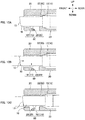
- Figs. 4A to 4D are explanatory diagrams illustrating how the connector is connected in the first embodiment.
- the optical connector 1 of the first embodiment is illustrated on the right-hand side in each figure.
- a counterpart connector and claws 91 of an adapter 90 are illustrated on the left-hand side in each figure.
- the outer structure of the adapter 90 is illustrated transparently by a dotted line.
- the upper diagram in each figure illustrates a top view, and the lower diagram illustrates a side view.
- the side view in each figure also illustrates an enlarged cross-sectional view of the pressing part 32's slide part 321 and the housing 20's guide face 25.
- an operator inserts the optical connector 1 into the adapter 90.
- the operator matches the key 21 of the optical connector 1 with a key groove (not illustrated) of the adapter 90 to thereby correctly orient the optical connector 1 in the up/down (vertical) direction, and in this state, inserts the front portion of the optical connector 1's housing 20 between the pair of claws 91 of the adapter 90.
- the optical connector 1 being inserted into the adapter 90 is a female-type connector
- the counterpart connector inside the adapter 90 is a male-type connector, but the male/female types may be reversed.
- the claws 91 of the adapter 90 move over the respective engagement parts 23 of the housing 20 and open outward, and the claws 91 of the adapter 90 come into contact with the front end surface 31 of the coupling 30, as illustrated in Fig. 4B .
- the guide pins 111 of the counterpart connector are already fitted inside the respective guide pin holes 11 of the optical connector 1.
- the claws 91 of the adapter 90 come into contact with the front end surface 31 of the coupling 30 after the guide pins 111 of the counterpart connector have been fitted inside the respective guide pin holes 11 of the optical connector 1.
- an upward force is applied to the ferrule 10 after the guide pins 111 of the counterpart connector have been fitted inside the respective guide pin holes 11 of the optical connector 1.
- the claws 91 of the adapter 90 cause the coupling 30 to slide rearward with respect to the housing 20, as illustrated in Fig. 4C .
- the pressing part 32 is provided to the coupling 30, and thus, the pressing part 32 also moves rearward relative to the housing 20 together with the coupling 30. At this time, as illustrated in Fig.
- the slide parts 321 of the pressing part 32 move upward while receding along the respective guide faces 25 of the housing 20; thereby, the pressing part 32 is displaced toward the lower surface of the ferrule 10 (i.e., the joining part 33 elastically deforms) and thus the pressing part 32 comes into contact with the lower surface of the ferrule 10; and thus, the pressing part 32 presses the ferrule 10.
- the pressing part 32 pressing the ferrule 10 an upward force is applied to the ferrule 10.
- the guide pins 111 of the counterpart connector are already fitted inside the respective guide pin holes 11 of the optical connector 1.
- the pressing part 32 comes into contact with the lower surface of the ferrule 10 after the guide pins 111 of the counterpart connector have been fitted inside the respective guide pin holes 11 of the optical connector 1.
- an upward force is applied to the ferrule 10 after the guide pins 111 of the counterpart connector have been fitted inside the respective guide pin holes 11 of the optical connector 1.
- the guide pins 111 will protrude toward the end face of the ferrule 10 which has been displaced in the up/down direction, and thus, the guide pins 111 may damage the inclined end face 13 in the periphery of the guide pin holes 11. In contrast, according to the present embodiment, such damage to the inclined end face 13 can be inhibited. Further, in the present embodiment, an upward force is applied to the ferrule 10 after fitting together the guide pins 111 and the guide pin holes 11; thus, the ferrule 10 can be displaced upward until the lower edge of each guide pin 111 comes into contact with the lower edge of the respective guide pin hole 11 as illustrated in Fig. 3B , thereby making it possible to displace the ferrule 10 upward by the previously anticipated amount.
- the inclined end face 13 of the ferrule 10 comes into contact with the inclined end face of the ferrule of the counterpart connector, as illustrated in Fig. 4D .
- the ferrule 10 receives force from the ferrule of the counterpart connector, and recedes with respect to the housing 20 against the elastic force of the spring 60 (see Fig. 2 ).
- the ferrules butt against one another by being pressed by the spring 60 with a predetermined force.
- the optical connector 1 can be connected with the counterpart connector in a state where the ferrule 10 has been displaced upward by the previously anticipated amount (see Fig. 3B ).
- the claws 91 of the adapter 90 move over the respective engagement parts 23 of the housing 20, engage with the respective engagement parts 23, and return to their original inwardly-closed state from the outwardly-opened state (see Fig. 4B ).
- the coupling 30, which has been slid rearward by the claws 91 of the adapter 90 is returned to its original position by the springs 20A, and thus slides frontward with respect to the housing 20.
- the claws 91 of the adapter 90 are prevented from opening outward by the inner wall surface of the coupling 30, and a latched state is retained.
- the pressing part 32 since the pressing part 32 is provided to the coupling 30, when the coupling 30 moves frontward relative to the housing 20, the pressing part 32 also moves frontward relative to the housing 20 together with the coupling 30, as illustrated in Fig. 4D . At this time, as illustrated in Fig. 4D , the pressing part 32 moves away from the ferrule 10 (the elastic deformation of the joining part 33 returns to its original state) while the slide parts 321 of the pressing part 32 are guided along the respective guide faces 25 of the housing 20, and thus, the force applied to the ferrule 10 by the pressing part 32 is released. As described above, in the present embodiment, after an upward force is once applied to the ferrule 10 at the time of connecting the connectors, the force applied to the ferrule 10 is released.
- the guide pins 111 will cause abrasion to the inner wall surface of the guide pin holes 11, and thus, the durability of the optical connector 1 is prone to deteriorate.
- abrasion of the guide pin holes 11 can be suppressed, and thus, the durability of the optical connector 1 is improved.
- the upward force applied by the pressing part 32 to the ferrule 10 is released after the inclined end face 13 of the ferrule 10 has come into contact with the inclined end face of the ferrule of the counterpart connector.
- a state in which the ferrule 10 has been upwardly displaced by the previously anticipated amount can be maintained easily, even after releasing the upward force applied to the ferrule 10.
- the upward force applied to the ferrule 10 by the pressing part 32 may be released before the inclined end face 13 of the ferrule 10 comes into contact with the inclined end face of the ferrule of the counterpart connector, so long as the upwardly-displaced state of the ferrule 10 can be maintained even after releasing the force applied to the ferrule 10.
- Fig. 5A is a perspective view of an optical connector 1 according to a second embodiment.
- Fig. 5B is an exploded perspective view wherein the coupling 30 is removed from the optical connector 1 of the second embodiment.
- the optical connector 1 (MPO connector) of the second embodiment includes a ferrule 10, a housing 20, and a coupling 30.
- the second embodiment also includes an application part 80 that is configured to apply an upward force to the ferrule 10 when connecting the connector.
- the application part 80 of the second embodiment includes a pressing part 27A provided to the housing 20.
- the pressing part 27A of the second embodiment is also a section that applies an upward force to the ferrule 10.
- the pressing part 27A indirectly applies an upward force to the ferrule 10 by applying an upward force to a pin clamp 50 (i.e., a member arranged on the rear side of the ferrule 10).
- a pressing member 27 is attached to the housing 20 of the second embodiment.
- the pressing member 27 includes the pressing part 27A and a fixing part 27B.
- the fixing part 27B is a section for fixing the pressing member 27 to the housing 20.
- the housing 20 and the pressing part 27A are formed as separate members, but the housing 20 and the pressing part 27Amay be formed integrally.
- a pressing hole 26 is formed in the housing 20.
- the pressing hole 26 is a through hole formed in the lower wall of the housing 20.
- the pressing part 27A is arranged in the pressing hole 26.
- the pressing part 27A is capable of being displaced (deformed) in the up/down direction inside the pressing hole 26.
- a release part 34 is formed in the coupling 30.
- the release part 34 is a section forming a space that allows the pressing part 27A to retreat.
- the release part 34 is a through hole, but it may be a non-through hole, such as a recess.
- the coupling 30's front edge 35 which is more toward the front than the release part 34, constitutes a section that presses the pressing part 27A.
- Figs. 6A and 6B are explanatory diagrams illustrating how the connector is connected in the second embodiment.
- the ferrule 10 is pressed frontward via the pin clamp 50 by the opposing force of the compressed-and-deformed spring 60 (not illustrated).
- the projection 22 on the inner wall surface of the housing 20 is in contact with the collar part 15 of the ferrule 10.
- the pressing part 27A is located inside the space formed by the release part 34 of the coupling 30, and a flange part 51 of the pin clamp 50 is arranged more toward the front than the pressing part 27A; thus, the pressing part 27A is not in contact with the pin clamp 50.
- the ferrule 10 When connecting the connector, as illustrated in Fig. 6B , the ferrule 10 receives force from the ferrule of the counterpart connector, and thereby, the ferrule 10 and the pin clamp 50 recede with respect to the housing 20 against the elastic force of the spring 60. As a result, the flange part 51 of the pin clamp 50 recedes to the position of the pressing part 27A. Further, when connecting the connector, as explained in Figs. 4B and 4C , the claws 91 of the adapter 90 cause the coupling 30 to slide rearward with respect to the housing 20. When the coupling 30 slides rearward with respect to the housing 20, the pressing part 27A receives force from the front edge 35 of the coupling 30 and is displaced upward.
- the pressing part 27A presses the flange part 51 of the pin clamp 50.
- the pressing part 27A which has received force from the coupling 30, presses the pin clamp 50, and thereby, an upward force is applied to the ferrule 10.
- an upward force is applied to the ferrule 10 after the inclined end face 13 of the ferrule 10 has come into contact with the inclined end face of the ferrule of the counterpart connector.
- the pressing part 27A needs to be arranged outside the housing 20 in order for the pressing part 27A to receive force from the coupling 30.
- the pressing part 27A needs to press the pin clamp 50 which is housed inside the housing 20.
- the pressing part 27A's size is reduced by configuring the pressing part 27A so as to press the outer edge of the flange part 51 of the pin clamp 50.
- an upward force is applied to the ferrule 10 by pressing the ferrule 10 from below.
- the method for applying an upward force to the ferrule 10 is not limited to methods of pressing the ferrule 10 from below.
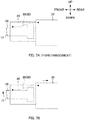
- Figs. 7A and 7B are schematic explanatory diagrams of an optical connector 1 according to a third embodiment.
- the optical connector 1 of the third embodiment includes a ferrule 10, a housing 20, and a coupling 30.
- the third embodiment also includes an application part 80 that is configured to apply an upward force to the ferrule 10 when connecting the connector.
- the application part 80 of the third embodiment includes a pulling member 36.
- One end of the pulling member 36 is fixed to the coupling 30, and the other end is fixed to the upper surface of the ferrule 10.
- the pulling member 36 is a thread-like or string-like member, but it may be a sheet-like member.
- the claws 91 of the adapter 90 cause the coupling 30 to slide rearward with respect to the housing 20.
- the coupling 30 slides rearward with respect to the housing 20, as illustrated in Fig. 7B , the pulling member 36's one end (the end fixed to the coupling 30) moves rearward, thereby causing the pulling member 36 to apply tension to the upper surface of the ferrule 10.
- an upward force is applied to the ferrule 10 at the inclined end face 13 of the ferrule 10.
- the pulling member 36 is constituted by an elastic member.
- the pulling member 36 is a string-like rubber member.
- the pulling member 36 stretches when the coupling 30 recedes and tension is applied to the pulling member 36 as illustrated in Fig. 7A , and this can prevent the ferrule 10 from receding before coming into contact with the counterpart connector's ferrule.
- the application part 80 applies an upward force to the ferrule 10 in conjunction with movement of the coupling 30 with respect to the housing 20.
- the movement amount of the coupling 30 (about 1.5 mm) is greater than the movement amount of the ferrule 10 (about 0.7 mm); thus, by adopting a configuration wherein force is applied to the ferrule 10 in conjunction with the movement of the coupling 30, it is easier to apply a large force and displacement to the ferrule 10 compared to a configuration where force is applied to the ferrule 10 in conjunction with the movement of the ferrule 10.
- the application part 80 may be configured so as to apply force to the ferrule 10 in conjunction with the movement of the ferrule 10.
- Fig. 8 is a perspective view of an optical connector 1 according to a fourth embodiment.
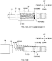
- Fig. 9A is a perspective view of a ferrule 10 of the fourth embodiment.
- the optical connector 1 of the fourth embodiment includes a ferrule 10 and a housing 20.
- the fourth embodiment also includes an application part 80 that is configured to apply an upward force to the ferrule 10 when connecting the connector.
- the application part 80 of the fourth embodiment includes: a protrusion 161 provided to the ferrule 10; and a contact part 28 provided to the housing 20.
- the protrusion 161 is a section provided on the lower side of the ferrule 10, and protrudes downward.
- the protrusion 161 is formed as a ridge along the width direction, but it may be shaped like a pin. When viewed from the left/right direction, the protrusion 161 tapers downward, and is formed with a sharp tip. With this shape, as described further below, after the protrusion 161 moves onto the contact part 28, it can move over the contact part 28 easily.
- the cross-sectional shape of the protrusion 161 as viewed from the left/right direction is triangular, but it may be semicircular with a rounded form. If the protrusion 161 does not have to move over the contact part 28, the protrusion 161 does not need to have a downwardly-tapered shape.
- the protrusion 161 is configured so as to protrude downward from the lower surface 14A of the ferrule 10. Note, however, that in cases where the lower surface 14A of the ferrule 10 is used as a reference surface for positioning the ferrule 10, the protrusion 161 may become a hindrance.
- Fig. 9B is a perspective view of a ferrule 10 according to a first modified example of the fourth embodiment.
- a depression 14B is formed in the lower surface 14A of the ferrule 10.
- the protrusion 161 is formed so as to protrude downward from the bottom surface of the depression 14B.
- the protrusion 161 is formed in the depression 14B so as not to protrude from the lower surface 14A of the ferrule 10. In this way, the protrusion 161 does not become a hindrance in cases where the lower surface 14A of the ferrule 10 is used as a reference surface for positioning the ferrule 10.
- the contact part 28 is a section that comes into contact with the protrusion 161.
- the contact part 28 is provided to a lower part of the housing 20.
- the contact part 28 is formed in a columnar shape along the width direction, but it may be shaped like a pin.
- Figs. 10A to 10C are explanatory diagrams illustrating how the connector is connected in the fourth embodiment.
- the ferrule 10 is housed in the housing 20 while being pressed frontward in a recedable manner.
- the ferrule 10 is in a position where the collar part 15 is in contact with the projection 22 of the housing 20.
- the protrusion 161 of the ferrule 10 is located frontward of the contact part 28 of the housing 20.
- the inclined end face 13 of the ferrule 10 comes into contact with the inclined end face of the ferrule of the counterpart connector, as illustrated in Fig. 10B .
- the ferrule 10 receives force from the ferrule of the counterpart connector, and recedes with respect to the housing 20 against the elastic force of the spring 60 (see Fig. 2 ).
- an upward force is applied to the ferrule 10 after the inclined end face 13 of the ferrule 10 has come into contact with the inclined end face of the ferrule of the counterpart connector.
- the protrusion 161 of the ferrule 10 is located rearward of the contact part 28 of the housing 20. Stated differently, at the time of connecting the connector, when the ferrule 10 recedes with respect to the housing 20, the protrusion 161 of the ferrule 10 moves over the contact part 28 of the housing 20. When the protrusion 161 of the ferrule 10 moves over the contact part 28 of the housing 20, the upward force applied to the ferrule 10 is released. In this way, in the fourth embodiment, after an upward force is once applied to the ferrule 10 at the time of connecting the connectors, the force applied to the ferrule 10 is released.
- the guide pins 111 will cause abrasion to the inner wall surface of the guide pin holes 11, and thus, the durability of the optical connector 1 is prone to deteriorate.
- the fourth embodiment by releasing the force applied to the ferrule 10, abrasion of the guide pin holes 11 can be suppressed, and thus, the durability of the optical connector 1 is improved.
- the protrusion 161 of the present embodiment is provided below the body part 14 of the ferrule 10.
- the contact part 28 can apply an upward force to the body part 14 of the ferrule 10 by contacting the protrusion 161 on the body part 14 of the ferrule 10, and can thus apply force to a section close to the inclined end face 13.
- This is advantageous because the end face of the optical fibers 3 can be displaced upward by the previously anticipated amount.
- the arrangement of the protrusion 161 is not limited to the above.
- Fig. 11A is an explanatory diagram of a second modified example of the fourth embodiment.
- the protrusion 162 is provided to the collar part 15 of the ferrule 10.
- the contact part 28 can apply an upward force to the ferrule 10 by contacting the protrusion 162 on the collar part 15 of the ferrule 10.
- the second modified example is also advantageous, because the end face of the optical fibers 3 can be displaced upward, compared to cases where no upward force is applied to the ferrule 10.
- Fig. 11B is an explanatory diagram of a third modified example of the fourth embodiment.
- the protrusion 511 is provided to a member (pin clamp 50) arranged on the rear side of the ferrule 10.
- the contact part 28 can apply an upward force to the ferrule 10 via the pin clamp 50 by contacting the protrusion 511 on the pin clamp 50.
- the third modified example is also advantageous, because the end face of the optical fibers 3 can be displaced upward, compared to cases where no upward force is applied to the ferrule 10.
- the application part 80 applies an upward force to the ferrule 10 in conjunction with the movement of the ferrule 10.
- the movement amount of the ferrule 10 when connecting the connector is about 0.7 mm, which is smaller than the movement amount of the coupling 30 (about 1.5 mm) when connecting the connector.
- an upward force can be applied to the ferrule 10.
- FIGs. 12A and 12B are explanatory diagrams of a fifth embodiment.
- An optical connector 1 (MPO connector) of the fifth embodiment includes a ferrule 10 and a housing 20.
- the optical connector 1 of the fifth embodiment also includes a coupling 30 outside the housing 20, and a floating mechanism 40 (a pin clamp 50, a spring 60, and a spring push member 70) housed inside the housing 20.
- Both ends of the spring 60 are each provided with a seat part 61.
- the seat part 61 is a section provided to each end of the spring 60, and is a section constituting a seat of the spring 60. In a natural state of the spring 60 (i.e., in a state neither expanded nor contracted), the seat part 61 has a plane that is perpendicular to the axial direction (expansion/contraction direction) of the spring 60.
- the spring push member 70 has an inclined part 72.
- the inclined part 72 is a section that inclines the seat part 61 at the rear end of the spring 60, and is arranged between the pair of arms 71 (see Fig. 2 ).
- the normal vector of the inclined surface of the inclined part 72 i.e., the surface that contacts the seat part 61
- the seat part 61 at the rear end of the spring 60 does not stay perpendicular to the front/rear direction, but inclines with respect to a plane that is parallel to the up/down direction and the left/right direction.
- the seat part 61 at the rear end of the spring 60 when the seat part 61 at the rear end of the spring 60 is butted against the inclined part 72, the seat part 61 at the front end of the spring 60 will be located more toward the upper side, as illustrated in Fig. 12B , than when the spring is housed in the connector.
- the seat part 61 at the front end of the spring 60 illustrated in Fig. 12B is displaced rearward and also displaced downward.
- the spring 60 housed inside the housing 20 is compressed and deformed in the front/rear direction, and the seat part 61 at the rear end of the spring 60 is not perpendicular to the spring 60's axial direction (herein, the front/rear direction), but is inclined with respect to a plane perpendicular to the spring 60's axial direction (i.e., a plane that is parallel to the up/down direction and the left/right direction) .
- the spring 60 i.e., the spring 60 illustrated in Fig. 12A housed inside the housing 20 in this way will press the ferrule 10 frontward and also apply an upward force thereto via the pin clamp 50.
- the application part 80 (spring 60) can apply an upward force to the ferrule 10, and thus, it is easy to displace the ferrule 10 upward by the previously anticipated amount.
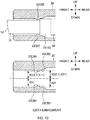
- Figs. 13A and 13B are explanatory diagrams of a sixth embodiment.
- the housing 20 of the sixth embodiment is usable as the housing 20 described in one of the foregoing first to fifth embodiments.
- the dot-and-dash line illustrated in Fig. 13B indicates the center position of a housing part (a housing part that houses the floating mechanism 40) in the rear section of the housing 20.
- X11 is the distance, in the up/down direction, between the dot-and-dash line and the projection 22 (the upper surface of the projection 22) on the lower-side inner wall surface of the housing 20.
- X12 is the distance, in the up/down direction, between the dot-and-dash line and the projection 22 (the lower surface of the projection 22) on the upper-side inner wall surface of the housing 20.
- An ordinary housing 20 is designed such that X11 and X12 have the same length and are not different.
- the center position between the upper and lower projections 22 matches the position of the dot-and-dash line.
- the sixth embodiment is designed such that X12 is longer than X11.
- the projections 22 are designed such that the center position between the upper and lower projections 22 is above the position of the dot-and-dash line.
- a collar housing part 29 for housing the front edge of the ferrule 10's collar part 15 is formed in the rear of the housing 20's projections 22.
- X21 is the distance, in the up/down direction, between the dot-and-dash line and the lower-side inner wall surface of the collar housing part 29.
- X22 is the distance, in the up/down direction, between the dot-and-dash line and the upper-side inner wall surface of the collar housing part 29.
- An ordinary housing 20 is designed such that X21 and X22 have the same length and are not different.
- the center position between the upper and lower inner wall surfaces of the collar housing part 29 matches the position of the dot-and-dash line.
- the sixth embodiment is designed such that X22 is longer than X21.
- the collar housing part 29 is designed such that the center position between the upper and lower inner wall surfaces of the collar housing part 29 is above the position of the dot-and-dash line.
- the foregoing embodiments are configured so that the application part 80 of the optical connector 1 applies an upward force to the ferrule 10 when connecting the optical connector with a counterpart connector.
- an operator may apply an upward force to the ferrule 10 with his/her fingertip when connecting the optical connector with a counterpart connector.
- an upward force can be applied to the ferrule 10, and thus, the ferrule 10 can be displaced upward by the previously anticipated amount.
- a configuration wherein the optical connector 1 includes an application part 80 and the application part applies an upward force to the ferrule 10 upon connection with a counterpart connector can achieve low loss stably, because force can be applied reliably to a predetermined location in a stable manner, compared to cases where force is applied by an operator.
Landscapes
- Physics & Mathematics (AREA)
- General Physics & Mathematics (AREA)
- Optics & Photonics (AREA)
- Mechanical Coupling Of Light Guides (AREA)
Abstract
Description
- The present invention relates to an optical connector and a method for connecting an optical connector.
- A known example of an optical connector is an MPO connector (F13-type multi-fiber optical connector compliant with JIS C5982). In this type of MPO connector, the connecting end face of a ferrule is polished in an oblique manner.
Patent Literature 1 describes that, when respective connecting end faces of such obliquely-polished ferrules are butted against one another, axial misalignment occurs between optical fibers as a result of the ferrules getting vertically displaced due to the clearance between each ferrule's guide pin hole and a positioning guide pin. In order to suppress an increase in optical loss caused by such axial misalignment between optical fibers (i.e., positional misalignment between optical fiber cores),Patent Literature 1 describes setting the position, in the up/down (vertical) direction, of optical fiber holes at a position slightly deviated from the guide pin hole's central axis by anticipating beforehand the amount of vertical displacement that the ferrules undergo. - Patent Literature 1:
JP 2005-181832A - At the time of butting the respective connecting end faces of obliquely-polished ferrules against one another, friction force between the connecting end faces may inhibit the ferrules from getting vertically displaced by the previously anticipated amount. However, the optical fiber holes of the aforementioned ferrule are provided at a position that takes into account beforehand the amount of vertical displacement of the ferrule; thus, if the ferrules do not get vertically displaced by the previously anticipated amount, connection loss between optical fibers will increase. Also, if the amount of vertical displacement of the ferrules varies every time the optical connector is connected/disconnected, variations will occur in the connection loss between optical fibers, thereby making it difficult to stably achieve low loss.
- An objective of the present invention is to stably achieve low loss.
- A primary aspect of the invention for achieving the aforementioned objective is an optical connector that includes: a ferrule including a guide pin hole, a plurality of fiber holes lined up in a width direction, and an inclined end face; a housing that houses the ferrule in a recedably pressed manner; and an application part that is configured to apply an upward force to the ferrule when connecting the optical connector with a counterpart connector, wherein a direction that is orthogonal to a connector connecting/disconnecting direction and to the width direction is defined as "up/down direction", and a side of the inclined end face that projects toward the counterpart connector is defined as "up".
- Other features of the present invention are disclosed in the following description and accompanying drawings.
- The present invention can stably achieve low loss.
-
- [
Fig. 1] Figs. 1A and 1B are perspective views of anoptical connector 1 according to a first embodiment. - [
Fig. 2] Fig. 2 is an exploded perspective view of theoptical connector 1 of the first embodiment. - [
Fig. 3] Figs. 3A and 3B are explanatory diagrams illustrating axial misalignment betweenferrules 10. - [
Fig. 4A] Fig. 4A is a first explanatory diagram illustrating how the connector is connected in the first embodiment. - [
Fig. 4B] Fig. 4B is a second explanatory diagram illustrating how the connector is connected in the first embodiment. - [
Fig. 4C] Fig. 4C is a third explanatory diagram illustrating how the connector is connected in the first embodiment. - [
Fig. 4D] Fig. 4D is a fourth explanatory diagram illustrating how the connector is connected in the first embodiment. - [
Fig. 5] Fig. 5A is a perspective view of anoptical connector 1 according to a second embodiment, andFig. 5B is an exploded perspective view wherein thecoupling 30 is removed from theoptical connector 1 of the second embodiment. - [
Fig. 6] Figs. 6A and 6B are explanatory diagrams illustrating how the connector is connected in the second embodiment. - [
Fig. 7] Figs. 7A and 7B are schematic explanatory diagrams of anoptical connector 1 according to a third embodiment. - [
Fig. 8] Fig. 8 is a perspective view of anoptical connector 1 according to a fourth embodiment. - [
Fig. 9] Fig. 9A is a perspective view of aferrule 10 of the fourth embodiment, andFig. 9B is a perspective view of aferrule 10 according to a first modified example of the fourth embodiment. - [
Fig. 10] Figs. 10A to 10C are explanatory diagrams illustrating how the connector is connected in the fourth embodiment. - [
Fig. 11] Fig. 11A is an explanatory diagram of a second modified example of the fourth embodiment, andFig. 11B is an explanatory diagram of a third modified example of the fourth embodiment. - [
Fig. 12] Figs. 12A and 12B are explanatory diagrams of a fifth embodiment. - [
Fig. 13 ] Figs. 13A and 13B are explanatory diagrams of a sixth embodiment. - At least the following features are disclosed in the following description and accompanying drawings.
- Disclosed is an optical connector that includes: a ferrule including a guide pin hole, a plurality of fiber holes lined up in a width direction, and an inclined end face; a housing that houses the ferrule in a recedably pressed manner; and an application part that is configured to apply an upward force to the ferrule when connecting the optical connector with a counterpart connector, wherein a direction that is orthogonal to a connector connecting/disconnecting direction and to the width direction is defined as "up/down direction", and a side of the inclined end face that projects toward the counterpart connector is defined as "up". With this optical connector, low loss can be achieved stably.
- Preferably, the application part applies an upward force to the ferrule after fitting together a guide pin and a guide pin hole when connecting the optical connector with the counterpart connector. Thus, damage to the inclined end face of the ferrule can be suppressed.
- Preferably, the application part applies an upward force to the ferrule before said inclined end face of said ferrule comes into contact with an inclined end face of a ferrule of the counterpart connector. Thus, an upward force can be applied to the ferrule before friction force acts on the inclined end face of the ferrule.
- Preferably, the application part releases the force applied to the ferrule after applying the upward force to the ferrule. Thus, the durability of the optical connector is improved.
- Preferably, the application part releases the force applied to the ferrule after said inclined end face of said ferrule comes into contact with an inclined end face of a ferrule of the counterpart connector. Thus, it is easy to maintain a state where the ferrule is displaced upward by an amount anticipated beforehand.
- Preferably, the application part applies an upward force to the ferrule by contacting a body part of the ferrule. Thus, force can be applied to a section close to the inclined end face, and thus, the end face of an optical fiber can be displaced upward by an amount anticipated beforehand.
- The application part may apply an upward force to the ferrule by contacting a collar part of the ferrule. Alternatively, the application part may apply an upward force to the ferrule by applying force to a member arranged on a rear side of the ferrule.
- Preferably, a coupling is mounted to the housing; and the application part applies an upward force to the ferrule in conjunction with movement of the coupling with respect to the housing. Because the amount of movement of the coupling at the time of connecting the connector is relatively large, it is easier to apply a large force and displacement to the ferrule compared to a configuration where force is applied to the ferrule in conjunction with the movement of the ferrule.
- Preferably, the application part includes a pressing part provided to the coupling; and when the coupling recedes with respect to the housing, the pressing part presses the ferrule upward by moving upward while receding along a guide face provided to the housing. Thus, an upward force can be applied to the ferrule by pressing.
- Preferably, the application part includes a pressing part provided to the housing; and when the coupling recedes with respect to the housing, the pressing part presses the ferrule upward by receiving force from the coupling. Thus, an upward force can be applied to the ferrule in conjunction with the movement of the coupling with respect to the housing, even in cases where the pressing part is not provided to the coupling.
- Preferably, the pressing part is provided on an opposite side from a side of the housing where a key is provided. Thus, the pressing part can be arranged without being constrained by the arrangement of the key.
- Preferably, the application part applies an upward force to the ferrule in conjunction with movement of the ferrule with respect to the housing. Thus, an upward force can be applied to the ferrule without being in conjunction with the movement of the coupling.
- Preferably, the application part includes a protrusion that moves together with the ferrule, and a contact part provided to the housing; and when the ferrule recedes with respect to the housing, the ferrule receives an upward force from the protrusion due to the protrusion coming into contact with the contact part. Thus, an upward force can be applied to the ferrule in conjunction with the movement of the ferrule with a simple configuration.
- Preferably, when the ferrule recedes with respect to the housing, the upward force to the ferrule is released due to the protrusion moving over the contact part. Thus, the durability of the optical connector is improved.
- Preferably, a depression is formed in a lower surface of the ferrule; and the protrusion is provided in the depression so as not to protrude below the lower surface of the ferrule. Thus, the lower surface of the ferrule can easily be used as a reference surface.
- Preferably, the application part is a spring that presses the ferrule frontward with respect to the housing; and a seat part at a rear end of the spring is inclined with respect to a plane perpendicular to an axial direction of the spring. Thus, an upward force can be applied to the ferrule with a simple configuration.
- Also disclosed is a method for connecting an optical connector that includes: a ferrule including a guide pin hole, a plurality of fiber holes lined up in a width direction, and an inclined end face; and a housing that houses the ferrule in a recedably pressed manner, the method involving: applying an upward force to the ferrule when connecting the optical connector with a counterpart connector, wherein a direction that is orthogonal to a connector connecting/disconnecting direction and to the width direction is defined as "up/down direction", and a side of the inclined end face that projects toward the counterpart connector is defined as "up". With this optical connector connecting method, low loss can be achieved stably.
-
Figs. 1A and 1B are perspective views of anoptical connector 1 according to a first embodiment.Fig. 2 is an exploded perspective view of theoptical connector 1 of the first embodiment. - In the description below, the various directions are defined as illustrated in
Figs. 1A and 1B . That is, the connecting/disconnecting direction (attaching/detaching direction) of theoptical connector 1 is defined as "front/rear direction", wherein the side toward a counterpart connector (not illustrated) is defined as "front", and the opposite side is defined as "rear". The direction in which a pair of guide pin holes 11 is lined up and in which a plurality of optical fiber holes 12 are lined up is defined as "left/right direction", wherein the right-hand side when viewed from the rear toward the front is defined as "right", and the opposite side is defined as "left". The left/right direction is also referred to as "width direction". The direction orthogonal to the "front/rear direction" and the "left/right direction (width direction)" is defined as "up/down direction", wherein the side of an inclined end face 13 of aferrule 10 that projects toward the front side (toward a counterpart connector) is defined as "up", and the opposite side is defined as "down". Theoptical connector 1's side where a key 21 is provided is "up". - The
optical connector 1 is a multifiber push-on (MPO) optical connector compliant with, for example, JIS C5982 or IEC 61754-7. Theoptical connector 1 includes aferrule 10 and ahousing 20. - The
ferrule 10 is a member that retains an end portion ofoptical fibers 3. Theferrule 10 includes guide pin holes 11, a plurality of fiber holes 12, and aninclined end face 13. Theferrule 10 also includes abody part 14 and acollar part 15. Thecollar part 15 is a section located more toward the rear side than thebody part 14 and is a section that projects more outward than thebody part 14. - Each
guide pin hole 11 is a hole in which aguide pin 111 is to be inserted. In cases where theoptical connector 1 is a male-type connector, aguide pin 111 is inserted in advance in eachguide pin hole 11 such that an end portion of theguide pin 111 projects from theguide pin hole 11. In cases where theoptical connector 1 is a female-type connector, aguide pin 111 of a counterpart connector will be inserted into theguide pin hole 11. Positioning betweenferrules 10 is achieved by fitting respective guide pins 111 into the guide pin holes 11 at the time of connecting the connectors. Theguide pin hole 11 thus serves as a section constituting a positioning part together with theguide pin 111. - The fiber holes 12 are holes in which end portions of respective
optical fibers 3 are to be inserted. An end portion of anoptical fiber 3 is fixed in eachfiber hole 12. In the present embodiment, theoptical fiber 3 inserted in eachfiber hole 12 is a single-mode optical fiber, but it may be a multi-mode optical fiber. - The inclined end face 13 is a connecting end face that is to be connected with a ferrule of a counterpart connector. The inclined end face 13 is inclined by about 8 degrees with respect to a plane perpendicular to the optical axis of the
optical fibers 3. The inclined end face 13 is formed by being obliquely polished together with the respective end faces of theoptical fibers 3 inserted in the respective fiber holes 12. Inclining the end face of theoptical fiber 3 reduces the light reflection amount at the connection point. - The
housing 20 is a cylindrical member that houses theferrule 10 in a recedably pressed manner. An inwardly-projectingprojection 22 is provided on the inner wall surface of thehousing 20. Theprojection 22 comes into contact with thecollar part 15 of theferrule 10, and thereby, theferrule 10, which is being pressed frontward, is prevented from falling out toward the front.Engagement parts 23 onto which claws 91 (described later) of anadapter 90 are latched are formed in the respective side surfaces of thehousing 20. - A
coupling 30 is arranged outside thehousing 20. Thecoupling 30 is a joining member that retains a state (latched state) in which claws 91 (described later) of anadapter 90 are caught by theengagement parts 23 of thehousing 20. Thecoupling 30 is provided so as to be slidable in the front/rear direction with respect to thehousing 20.Springs 20A are arranged between thecoupling 30 and thehousing 20, and thesprings 20A recedably press thecoupling 30 frontward with respect to thehousing 20. When in a state (latched state) in which theclaws 91 of the adapter 90 (described later) are caught by theengagement parts 23 of thehousing 20, the inner wall surface of thecoupling 30 prevents theclaws 91 of theadapter 90 from opening outward, thereby retaining the latched state. When removing theoptical connector 1, thecoupling 30 is slid rearward with respect to thehousing 20, and this allows theclaws 91 of theadapter 90 to open outward, thereby releasing the latched state. - The
housing 20 also houses a floatingmechanism 40 that presses theferrule 10 frontward.Fig. 2 illustrates a floatingmechanism 40 housed in thehousing 20. - The floating
mechanism 40 is a mechanism that presses theferrule 10 frontward. The floatingmechanism 40 includes apin clamp 50, aspring 60, and aspring push member 70. Thepin clamp 50 is a member arranged on the rear side of theferrule 10. In cases where theoptical connector 1 is a male-type connector, thepin clamp 50 retains the respective rear ends of the guide pins 111. In this case, the guide pins 111 will penetrate the respective guide pin holes 11 in theferrule 10, and the respective tip ends of the guide pins 111 will project out from theinclined end face 13. A front end portion of thespring 60 is fixed to the rear portion of thepin clamp 50. Thespring 60 is an elastic member that applies pressing force for pressing theferrule 10 frontward. Thespring 60 is housed in thehousing 20 in a compressed and deformed state between thepin clamp 50 and thespring push member 70. The front end portion of thespring 60 is fixed to thepin clamp 50, and the rear end portion of thespring 60 is fixed to thespring push member 70. Thespring push member 70 is a member that allows thespring 60 to be housed in thehousing 20 in a compressed state. Thespring push member 70 includes a pair ofarms 71. Thespring 60 is housed in a space between the pair ofarms 71. At the front end of eacharm 71, alug 711 is formed outwardly. By making thelug 711 engage with awindow 24 formed in the side surface of thehousing 20, thespring 60 is housed inside thehousing 20 in a compressed state. Thus, theferrule 10 is pressed frontward via thepin clamp 50 by the opposing force of the compressed-and-deformed spring 60. -
Figs. 3A and 3B are explanatory diagrams illustrating axial misalignment betweenferrules 10. - As described above, positioning between
ferrules 10 is achieved by fitting respective guide pins 111 into the guide pin holes 11 at the time of connecting the connectors. Note, however, that the diameter of theguide pin hole 11 is formed larger than the diameter of theguide pin 111, and thus, there is a clearance (gap) between theguide pin hole 11 and theguide pin 111. Meanwhile, theferrule 10 has aninclined end face 13, and at the time of connecting the connectors, the respective inclined end faces 13 of theferrules 10 butt against one another in a frontwardly-pressed state. As a result, theferrule 10 shifts so as to slide along the inclined end face 13 of the counterpart connector, thereby causing theferrule 10 to be relatively displaced in the up/down direction. - So, taking into account beforehand the amount of positional displacement as illustrated in
Fig. 3B , the fiber holes 12 of theferrule 10 of the present embodiment are provided at a position slightly deviated in the up/down direction from theguide pin hole 11's central axis. As illustrated inFig. 3B , it is anticipated that theferrule 10 will be relatively displaced in the up/down direction until the lower edge of theguide pin 111 comes into contact with the lower edge of theguide pin hole 11. So, when the diameter of theguide pin 111 is defined as D1 and the diameter of theguide pin hole 11 is defined as D2, the fiber holes 12 are provided at a position that is deviated in the up/down direction from theguide pin hole 11's central axis by an offset amount of (D2-D1)/2. It should be noted that, in cases where the fiber holes 12 are inclined with respect to theguide pin hole 11, the offset amount is not necessarily limited to (D2-D1)/2, as it is necessary to take into account eccentricity caused during oblique polishing. - As described above, the optical fiber holes 12 are provided at a position that takes into account beforehand the amount of vertical displacement of the
ferrule 10. So, if theferrule 10 is not vertically displaced by the previously anticipated amount at the time of butting the connecting end faces of theferrules 10 against one another, this will lead to an increase in connection loss betweenoptical fibers 3. Note that, friction force between the inclined end faces 13 may inhibit theferrules 10 from getting vertically displaced by the previously anticipated amount. More specifically, there are cases where theferrules 10 are not relatively displaced in the up/down direction to an extent that the lower edge of theguide pin 111 contacts the lower edge of theguide pin hole 11 as illustrated inFig. 3B . - So, as described below, the
optical connector 1 of the present embodiment includes anapplication part 80 that is configured to apply an upward force to theferrule 10 when connecting the connector. By making theapplication part 80 apply an upward force to theferrule 10, theoptical connector 1 can connect with a counterpart connector in a state where theferrule 10 is displaced in the up/down direction by the previously anticipated amount (seeFig. 3B ). Thus, connection loss betweenoptical fibers 3 can be suppressed, and low loss can be achieved stably. - The
application part 80 of the first embodiment includes apressing part 32 provided to the coupling 30 (seeFig. 1B andFig. 2 ). Thepressing part 32 is a section that applies an upward force to theferrule 10 by pressing theferrule 10. Thepressing part 32 of the first embodiment directly applies pressing force to theferrule 10 by directly contacting the lower surface of theferrule 10. - The
pressing part 32 of the present embodiment is arranged below thebody part 14 of theferrule 10. Thus, thepressing part 32 applies an upward force to thebody part 14 of theferrule 10. Applying an upward force to thebody part 14 of theferrule 10 is advantageous, because it is possible to apply force to a section closer to the inclined end face 13 compared to cases where an upward force is applied to thecollar part 15 of theferrule 10, and thereby the end face of theoptical fibers 3 can be displaced upward by the previously anticipated amount. - In the present embodiment, the
pressing part 32 is arranged at the front edge of the housing 20 (seeFig. 1B ). This is advantageous because force can be applied to a section close to the inclined end face 13 of theferrule 10. If thepressing part 32 is arranged so as to protrude more toward the front than the front edge of thehousing 20, then, at the time of connecting the connectors, thepressing part 32 may come into contact with the counterpart connector or theadapter 90. Thus, in cases of providing thepressing part 32 as much as possible toward the front side, it is preferable to arrange thepressing part 32 at the front edge of thehousing 20, as in the present embodiment. - In cases of applying an upward force to the
ferrule 10 by pressing theferrule 10, thepressing part 32 is provided on the opposite side from the side of thehousing 20 where a key 21 is provided. In MPO connectors, the side of the inclined end face 13 of theferrule 10 provided with the key 21 is the side that projects toward the counterpart connector. Thus, thepressing part 32 is formed on the side where the key 21 is not provided. This is advantageous in cases of applying an upward force to theferrule 10 by pressing theferrule 10, because thepressing part 32 can be arranged without being constrained by the arrangement of the key 21. - The
pressing part 32 is joined to thecoupling 30 via a joiningpart 33. In the present embodiment, thepressing part 32 and the joiningpart 33 are molded integrally with thecoupling 30, but thepressing part 32 and the joiningpart 33 may be formed as separate members from thecoupling 30. - The joining
part 33 is a plate-shaped member that extends frontward from the front edge of thecoupling 30. The rear end of the joiningpart 33 is fixed to thecoupling 30, and thepressing part 32 is formed at the front end of the joiningpart 33. The joiningpart 33 is formed in a cantilever fashion, and is elastically deformable. The elastic deformation of the joiningpart 33 enables thepressing part 32 to be displaced in the up/down (vertical) direction. - The
pressing part 32 of the first embodiment includesslide parts 321. Theslide part 321 is a section that comes into contact with aguide face 25 of thehousing 20. Thepressing part 32 is formed wider than the joiningpart 33, and the sections projecting outward toward the left and right from the joiningpart 33 constitute theslide parts 321. Stated differently, a pair ofslide parts 321 is formed, one on each of the left and right edges of thepressing part 32. By forming a pair of left andright slide parts 321, the displacement of thepressing part 32 in the up/down direction can be made more stable compared to cases where theslide part 321 is provided only in one location. - The
housing 20 of the first embodiment has guide faces 25 at sections that come into contact with therespective slide parts 321. The guide face 25 is formed on the lower-side inner wall of thehousing 20, and is formed as an inclined surface that rises toward the rear. The guide face 25 serves as a section that guides theslide part 321. As theslide parts 321 are guided along the respective guide faces 25, thepressing part 32 is displaced so as to move closer to or away from the lower surface of theferrule 10. The present embodiment includes a pair ofslide parts 321, and thus also includes a pair of guide faces 25. -
Figs. 4A to 4D are explanatory diagrams illustrating how the connector is connected in the first embodiment. Theoptical connector 1 of the first embodiment is illustrated on the right-hand side in each figure. A counterpart connector andclaws 91 of anadapter 90 are illustrated on the left-hand side in each figure. To illustrate the counterpart connector and theclaws 91, which are inside theadapter 90, the outer structure of theadapter 90 is illustrated transparently by a dotted line. The upper diagram in each figure illustrates a top view, and the lower diagram illustrates a side view. The side view in each figure also illustrates an enlarged cross-sectional view of thepressing part 32'sslide part 321 and thehousing 20'sguide face 25. - As illustrated in
Fig. 4A , at the time of connecting the connectors, an operator inserts theoptical connector 1 into theadapter 90. The operator matches the key 21 of theoptical connector 1 with a key groove (not illustrated) of theadapter 90 to thereby correctly orient theoptical connector 1 in the up/down (vertical) direction, and in this state, inserts the front portion of theoptical connector 1'shousing 20 between the pair ofclaws 91 of theadapter 90. In this embodiment, as illustrated inFig. 4A , theoptical connector 1 being inserted into theadapter 90 is a female-type connector, and the counterpart connector inside theadapter 90 is a male-type connector, but the male/female types may be reversed. - As the
optical connector 1 is inserted into theadapter 90 and theoptical connector 1 is brought closer to the counterpart connector, theclaws 91 of theadapter 90 move over therespective engagement parts 23 of thehousing 20 and open outward, and theclaws 91 of theadapter 90 come into contact with thefront end surface 31 of thecoupling 30, as illustrated inFig. 4B . In the present embodiment, as illustrated inFig. 4B , at the stage where theclaws 91 of theadapter 90 contact thefront end surface 31 of thecoupling 30, the guide pins 111 of the counterpart connector are already fitted inside the respective guide pin holes 11 of theoptical connector 1. Stated differently, in the present embodiment, theclaws 91 of theadapter 90 come into contact with thefront end surface 31 of thecoupling 30 after the guide pins 111 of the counterpart connector have been fitted inside the respective guide pin holes 11 of theoptical connector 1. Thus, as described further below, an upward force is applied to theferrule 10 after the guide pins 111 of the counterpart connector have been fitted inside the respective guide pin holes 11 of theoptical connector 1. - When the operator further inserts the
optical connector 1 into theadapter 90 from the state illustrated inFig. 4B , theclaws 91 of theadapter 90 cause thecoupling 30 to slide rearward with respect to thehousing 20, as illustrated inFig. 4C . In the present embodiment, thepressing part 32 is provided to thecoupling 30, and thus, thepressing part 32 also moves rearward relative to thehousing 20 together with thecoupling 30. At this time, as illustrated inFig. 4C , theslide parts 321 of thepressing part 32 move upward while receding along the respective guide faces 25 of thehousing 20; thereby, thepressing part 32 is displaced toward the lower surface of the ferrule 10 (i.e., the joiningpart 33 elastically deforms) and thus thepressing part 32 comes into contact with the lower surface of theferrule 10; and thus, thepressing part 32 presses theferrule 10. As a result of thepressing part 32 pressing theferrule 10, an upward force is applied to theferrule 10. - As illustrated in
Fig. 4C , at the stage where thepressing part 32 is in contact with the lower surface of theferrule 10, the guide pins 111 of the counterpart connector are already fitted inside the respective guide pin holes 11 of theoptical connector 1. Stated differently, in the present embodiment, thepressing part 32 comes into contact with the lower surface of theferrule 10 after the guide pins 111 of the counterpart connector have been fitted inside the respective guide pin holes 11 of theoptical connector 1. Thus, an upward force is applied to theferrule 10 after the guide pins 111 of the counterpart connector have been fitted inside the respective guide pin holes 11 of theoptical connector 1. If fitting of the guide pins 111 into the respective guide pin holes 11 is performed after applying an upward force to theferrule 10, the guide pins 111 will protrude toward the end face of theferrule 10 which has been displaced in the up/down direction, and thus, the guide pins 111 may damage the inclined end face 13 in the periphery of the guide pin holes 11. In contrast, according to the present embodiment, such damage to the inclined end face 13 can be inhibited. Further, in the present embodiment, an upward force is applied to theferrule 10 after fitting together the guide pins 111 and the guide pin holes 11; thus, theferrule 10 can be displaced upward until the lower edge of eachguide pin 111 comes into contact with the lower edge of the respectiveguide pin hole 11 as illustrated inFig. 3B , thereby making it possible to displace theferrule 10 upward by the previously anticipated amount. - Further, as illustrated in
Fig. 4C , at the stage where thepressing part 32 contacts the lower surface of theferrule 10, the inclined end face 13 of theferrule 10 is still not in contact with the inclined end face of the ferrule of the counterpart connector. Thus, in the present embodiment, an upward force is applied to theferrule 10 before the inclined end face 13 of theferrule 10 comes into contact with the inclined end face of the ferrule of the counterpart connector. If an upward force is applied to theferrule 10 after the inclined end face 13 of theferrule 10 has contacted the inclined end face of the ferrule of the counterpart connector, then an upward force will be applied to theferrule 10 in a state where friction force is acting on the inclined end face 13 of theferrule 10. In contrast, in the present embodiment, an upward force can be applied to theferrule 10 before such friction force acts on the inclined end face 13 of theferrule 10, and thus, it is easy to displace theferrule 10 upward by the previously anticipated amount. - When the operator further inserts the
optical connector 1 into theadapter 90 from the state illustrated inFig. 4C , the inclined end face 13 of theferrule 10 comes into contact with the inclined end face of the ferrule of the counterpart connector, as illustrated inFig. 4D . At this time, theferrule 10 receives force from the ferrule of the counterpart connector, and recedes with respect to thehousing 20 against the elastic force of the spring 60 (seeFig. 2 ). The ferrules butt against one another by being pressed by thespring 60 with a predetermined force. In the present embodiment, because an upward force has been applied to theferrule 10, theoptical connector 1 can be connected with the counterpart connector in a state where theferrule 10 has been displaced upward by the previously anticipated amount (seeFig. 3B ). - When the
optical connector 1 is connected with the counterpart connector, theclaws 91 of theadapter 90 move over therespective engagement parts 23 of thehousing 20, engage with therespective engagement parts 23, and return to their original inwardly-closed state from the outwardly-opened state (seeFig. 4B ). At this time, thecoupling 30, which has been slid rearward by theclaws 91 of theadapter 90, is returned to its original position by thesprings 20A, and thus slides frontward with respect to thehousing 20. As a result of thecoupling 30 sliding frontward, theclaws 91 of theadapter 90 are prevented from opening outward by the inner wall surface of thecoupling 30, and a latched state is retained. - In the present embodiment, since the
pressing part 32 is provided to thecoupling 30, when thecoupling 30 moves frontward relative to thehousing 20, thepressing part 32 also moves frontward relative to thehousing 20 together with thecoupling 30, as illustrated inFig. 4D . At this time, as illustrated inFig. 4D , thepressing part 32 moves away from the ferrule 10 (the elastic deformation of the joiningpart 33 returns to its original state) while theslide parts 321 of thepressing part 32 are guided along the respective guide faces 25 of thehousing 20, and thus, the force applied to theferrule 10 by thepressing part 32 is released. As described above, in the present embodiment, after an upward force is once applied to theferrule 10 at the time of connecting the connectors, the force applied to theferrule 10 is released. If the upward force applied to theferrule 10 is not released and thepressing part 32 keeps applying the upward force to theferrule 10, the guide pins 111 will cause abrasion to the inner wall surface of the guide pin holes 11, and thus, the durability of theoptical connector 1 is prone to deteriorate. In contrast, in the present embodiment, by releasing the force applied to theferrule 10, abrasion of the guide pin holes 11 can be suppressed, and thus, the durability of theoptical connector 1 is improved. - In the present embodiment, the upward force applied by the
pressing part 32 to theferrule 10 is released after the inclined end face 13 of theferrule 10 has come into contact with the inclined end face of the ferrule of the counterpart connector. Thus, a state in which theferrule 10 has been upwardly displaced by the previously anticipated amount can be maintained easily, even after releasing the upward force applied to theferrule 10. Note, however, that the upward force applied to theferrule 10 by thepressing part 32 may be released before the inclined end face 13 of theferrule 10 comes into contact with the inclined end face of the ferrule of the counterpart connector, so long as the upwardly-displaced state of theferrule 10 can be maintained even after releasing the force applied to theferrule 10. -
Fig. 5A is a perspective view of anoptical connector 1 according to a second embodiment.Fig. 5B is an exploded perspective view wherein thecoupling 30 is removed from theoptical connector 1 of the second embodiment. The optical connector 1 (MPO connector) of the second embodiment includes aferrule 10, ahousing 20, and acoupling 30. - The second embodiment also includes an
application part 80 that is configured to apply an upward force to theferrule 10 when connecting the connector. Theapplication part 80 of the second embodiment includes apressing part 27A provided to thehousing 20. Thepressing part 27A of the second embodiment is also a section that applies an upward force to theferrule 10. In the second embodiment, however, instead of directly applying force to theferrule 10 by contacting theferrule 10, thepressing part 27A indirectly applies an upward force to theferrule 10 by applying an upward force to a pin clamp 50 (i.e., a member arranged on the rear side of the ferrule 10). - A pressing
member 27 is attached to thehousing 20 of the second embodiment. The pressingmember 27 includes thepressing part 27A and a fixingpart 27B. The fixingpart 27B is a section for fixing the pressingmember 27 to thehousing 20. In the present embodiment, thehousing 20 and thepressing part 27A are formed as separate members, but thehousing 20 and the pressing part 27Amay be formed integrally. - A
pressing hole 26 is formed in thehousing 20. Thepressing hole 26 is a through hole formed in the lower wall of thehousing 20. Thepressing part 27A is arranged in thepressing hole 26. Thepressing part 27A is capable of being displaced (deformed) in the up/down direction inside thepressing hole 26. - A
release part 34 is formed in thecoupling 30. Therelease part 34 is a section forming a space that allows thepressing part 27A to retreat. In this example, therelease part 34 is a through hole, but it may be a non-through hole, such as a recess. Thecoupling 30'sfront edge 35, which is more toward the front than therelease part 34, constitutes a section that presses thepressing part 27A. -
Figs. 6A and 6B are explanatory diagrams illustrating how the connector is connected in the second embodiment. - As illustrated in
Fig. 6A , in a state before connection of the connector, theferrule 10 is pressed frontward via thepin clamp 50 by the opposing force of the compressed-and-deformed spring 60 (not illustrated). Thus, theprojection 22 on the inner wall surface of thehousing 20 is in contact with thecollar part 15 of theferrule 10. At this stage, thepressing part 27A is located inside the space formed by therelease part 34 of thecoupling 30, and aflange part 51 of thepin clamp 50 is arranged more toward the front than thepressing part 27A; thus, thepressing part 27A is not in contact with thepin clamp 50. - When connecting the connector, as illustrated in
Fig. 6B , theferrule 10 receives force from the ferrule of the counterpart connector, and thereby, theferrule 10 and thepin clamp 50 recede with respect to thehousing 20 against the elastic force of thespring 60. As a result, theflange part 51 of thepin clamp 50 recedes to the position of thepressing part 27A. Further, when connecting the connector, as explained inFigs. 4B and4C , theclaws 91 of theadapter 90 cause thecoupling 30 to slide rearward with respect to thehousing 20. When thecoupling 30 slides rearward with respect to thehousing 20, thepressing part 27A receives force from thefront edge 35 of thecoupling 30 and is displaced upward. Thus, thepressing part 27A presses theflange part 51 of thepin clamp 50. As described above, in the second embodiment, thepressing part 27A, which has received force from thecoupling 30, presses thepin clamp 50, and thereby, an upward force is applied to theferrule 10. - In the second embodiment, an upward force is applied to the
ferrule 10 after the inclined end face 13 of theferrule 10 has come into contact with the inclined end face of the ferrule of the counterpart connector. Thus, even if theferrule 10 has not been displaced vertically by the previously anticipated amount because of friction force acting on the inclined end face 13 of theferrule 10, the application of an upward force to theferrule 10 can displace theferrule 10 upward by the previously anticipated amount against the friction force acting on theinclined end face 13. - In the second embodiment, at least a portion of the
pressing part 27A needs to be arranged outside thehousing 20 in order for thepressing part 27A to receive force from thecoupling 30. On the other hand, thepressing part 27A needs to press thepin clamp 50 which is housed inside thehousing 20. In the present embodiment, thepressing part 27A's size is reduced by configuring thepressing part 27A so as to press the outer edge of theflange part 51 of thepin clamp 50. - In the foregoing first and second embodiments, an upward force is applied to the
ferrule 10 by pressing theferrule 10 from below. However, the method for applying an upward force to theferrule 10 is not limited to methods of pressing theferrule 10 from below. -
Figs. 7A and 7B are schematic explanatory diagrams of anoptical connector 1 according to a third embodiment. Theoptical connector 1 of the third embodiment includes aferrule 10, ahousing 20, and acoupling 30. - The third embodiment also includes an
application part 80 that is configured to apply an upward force to theferrule 10 when connecting the connector. Theapplication part 80 of the third embodiment includes a pullingmember 36. One end of the pullingmember 36 is fixed to thecoupling 30, and the other end is fixed to the upper surface of theferrule 10. In the present embodiment, the pullingmember 36 is a thread-like or string-like member, but it may be a sheet-like member. - When connecting the connector, as explained in
Figs. 4B and4C , theclaws 91 of theadapter 90 cause thecoupling 30 to slide rearward with respect to thehousing 20. When thecoupling 30 slides rearward with respect to thehousing 20, as illustrated inFig. 7B , the pullingmember 36's one end (the end fixed to the coupling 30) moves rearward, thereby causing the pullingmember 36 to apply tension to the upper surface of theferrule 10. As a result, an upward force is applied to theferrule 10 at the inclined end face 13 of theferrule 10. - In the present embodiment, the pulling
member 36 is constituted by an elastic member. In the present embodiment, the pullingmember 36 is a string-like rubber member. By constituting the pullingmember 36 by an elastic member, the pullingmember 36 stretches when thecoupling 30 recedes and tension is applied to the pullingmember 36 as illustrated inFig. 7A , and this can prevent theferrule 10 from receding before coming into contact with the counterpart connector's ferrule. - In the foregoing first to third embodiments, the
application part 80 applies an upward force to theferrule 10 in conjunction with movement of thecoupling 30 with respect to thehousing 20. When connecting the connector, the movement amount of the coupling 30 (about 1.5 mm) is greater than the movement amount of the ferrule 10 (about 0.7 mm); thus, by adopting a configuration wherein force is applied to theferrule 10 in conjunction with the movement of thecoupling 30, it is easier to apply a large force and displacement to theferrule 10 compared to a configuration where force is applied to theferrule 10 in conjunction with the movement of theferrule 10. However, as described in the following embodiments, theapplication part 80 may be configured so as to apply force to theferrule 10 in conjunction with the movement of theferrule 10. -
Fig. 8 is a perspective view of anoptical connector 1 according to a fourth embodiment.Fig. 9A is a perspective view of aferrule 10 of the fourth embodiment. Theoptical connector 1 of the fourth embodiment includes aferrule 10 and ahousing 20. - The fourth embodiment also includes an
application part 80 that is configured to apply an upward force to theferrule 10 when connecting the connector. Theapplication part 80 of the fourth embodiment includes: aprotrusion 161 provided to theferrule 10; and acontact part 28 provided to thehousing 20. - The
protrusion 161 is a section provided on the lower side of theferrule 10, and protrudes downward. In the present embodiment, theprotrusion 161 is formed as a ridge along the width direction, but it may be shaped like a pin. When viewed from the left/right direction, theprotrusion 161 tapers downward, and is formed with a sharp tip. With this shape, as described further below, after theprotrusion 161 moves onto thecontact part 28, it can move over thecontact part 28 easily. In the present embodiment, the cross-sectional shape of theprotrusion 161 as viewed from the left/right direction is triangular, but it may be semicircular with a rounded form. If theprotrusion 161 does not have to move over thecontact part 28, theprotrusion 161 does not need to have a downwardly-tapered shape. - In the present embodiment, as illustrated in
Fig. 9A , theprotrusion 161 is configured so as to protrude downward from thelower surface 14A of theferrule 10. Note, however, that in cases where thelower surface 14A of theferrule 10 is used as a reference surface for positioning theferrule 10, theprotrusion 161 may become a hindrance. -
Fig. 9B is a perspective view of aferrule 10 according to a first modified example of the fourth embodiment. In the first modified example, adepression 14B is formed in thelower surface 14A of theferrule 10. Further, in the first modified example, theprotrusion 161 is formed so as to protrude downward from the bottom surface of thedepression 14B. In the first modified example, theprotrusion 161 is formed in thedepression 14B so as not to protrude from thelower surface 14A of theferrule 10. In this way, theprotrusion 161 does not become a hindrance in cases where thelower surface 14A of theferrule 10 is used as a reference surface for positioning theferrule 10. - The
contact part 28 is a section that comes into contact with theprotrusion 161. Thecontact part 28 is provided to a lower part of thehousing 20. In the present embodiment, thecontact part 28 is formed in a columnar shape along the width direction, but it may be shaped like a pin. -
Figs. 10A to 10C are explanatory diagrams illustrating how the connector is connected in the fourth embodiment. - As described above, the
ferrule 10 is housed in thehousing 20 while being pressed frontward in a recedable manner. At the stage before connecting the connector, as illustrated inFig. 10A , theferrule 10 is in a position where thecollar part 15 is in contact with theprojection 22 of thehousing 20. At the position where thecollar part 15 is in contact with theprojection 22 of thehousing 20, theprotrusion 161 of theferrule 10 is located frontward of thecontact part 28 of thehousing 20. - Further, as described above, when the operator inserts the
optical connector 1 into theadapter 90, the inclined end face 13 of theferrule 10 comes into contact with the inclined end face of the ferrule of the counterpart connector, as illustrated inFig. 10B . At this time, theferrule 10 receives force from the ferrule of the counterpart connector, and recedes with respect to thehousing 20 against the elastic force of the spring 60 (seeFig. 2 ). - When the
ferrule 10 recedes as illustrated inFig. 10B , theprotrusion 161 of theferrule 10 comes into contact with thecontact part 28 of thehousing 20. As theferrule 10 recedes further, theprotrusion 161 of theferrule 10 moves onto thecontact part 28, and as a result, an upward force is applied to theferrule 10. - In the fourth embodiment, an upward force is applied to the
ferrule 10 after the inclined end face 13 of theferrule 10 has come into contact with the inclined end face of the ferrule of the counterpart connector. Thus, even if theferrule 10 has not been displaced vertically by the previously anticipated amount because of friction force acting on the inclined end face 13 of theferrule 10, the application of an upward force to theferrule 10 can displace theferrule 10 upward by the previously anticipated amount against the friction force acting on theinclined end face 13. - When the
optical connector 1 is connected to the counterpart connector, as illustrated inFig. 10C , theprotrusion 161 of theferrule 10 is located rearward of thecontact part 28 of thehousing 20. Stated differently, at the time of connecting the connector, when theferrule 10 recedes with respect to thehousing 20, theprotrusion 161 of theferrule 10 moves over thecontact part 28 of thehousing 20. When theprotrusion 161 of theferrule 10 moves over thecontact part 28 of thehousing 20, the upward force applied to theferrule 10 is released. In this way, in the fourth embodiment, after an upward force is once applied to theferrule 10 at the time of connecting the connectors, the force applied to theferrule 10 is released. If the upward force applied to theferrule 10 is not released and the application part 80 (theprotrusion 161 and the contact part 28) keeps applying the upward force to theferrule 10, the guide pins 111 will cause abrasion to the inner wall surface of the guide pin holes 11, and thus, the durability of theoptical connector 1 is prone to deteriorate. In contrast, in the fourth embodiment, by releasing the force applied to theferrule 10, abrasion of the guide pin holes 11 can be suppressed, and thus, the durability of theoptical connector 1 is improved. - The
protrusion 161 of the present embodiment is provided below thebody part 14 of theferrule 10. Thus, thecontact part 28 can apply an upward force to thebody part 14 of theferrule 10 by contacting theprotrusion 161 on thebody part 14 of theferrule 10, and can thus apply force to a section close to theinclined end face 13. This is advantageous because the end face of theoptical fibers 3 can be displaced upward by the previously anticipated amount. Note, however, that the arrangement of theprotrusion 161 is not limited to the above. -
Fig. 11A is an explanatory diagram of a second modified example of the fourth embodiment. In the second modified example, the protrusion 162 is provided to thecollar part 15 of theferrule 10. According to the second modified example, thecontact part 28 can apply an upward force to theferrule 10 by contacting the protrusion 162 on thecollar part 15 of theferrule 10. The second modified example is also advantageous, because the end face of theoptical fibers 3 can be displaced upward, compared to cases where no upward force is applied to theferrule 10. -
Fig. 11B is an explanatory diagram of a third modified example of the fourth embodiment. In the third modified example, theprotrusion 511 is provided to a member (pin clamp 50) arranged on the rear side of theferrule 10. According to the third modified example, thecontact part 28 can apply an upward force to theferrule 10 via thepin clamp 50 by contacting theprotrusion 511 on thepin clamp 50. The third modified example is also advantageous, because the end face of theoptical fibers 3 can be displaced upward, compared to cases where no upward force is applied to theferrule 10. - In the foregoing fourth embodiment (including the first to third modified examples), the
application part 80 applies an upward force to theferrule 10 in conjunction with the movement of theferrule 10. The movement amount of theferrule 10 when connecting the connector is about 0.7 mm, which is smaller than the movement amount of the coupling 30 (about 1.5 mm) when connecting the connector. However, by configuring the protrusion and thecontact part 28 so that the protrusion can move onto (or move over) thecontact part 28 at the time of movement of theferrule 10, an upward force can be applied to theferrule 10. -
Figs. 12A and 12B are explanatory diagrams of a fifth embodiment. An optical connector 1 (MPO connector) of the fifth embodiment includes aferrule 10 and ahousing 20. Theoptical connector 1 of the fifth embodiment also includes acoupling 30 outside thehousing 20, and a floating mechanism 40 (apin clamp 50, aspring 60, and a spring push member 70) housed inside thehousing 20. - Both ends of the
spring 60 are each provided with aseat part 61. Theseat part 61 is a section provided to each end of thespring 60, and is a section constituting a seat of thespring 60. In a natural state of the spring 60 (i.e., in a state neither expanded nor contracted), theseat part 61 has a plane that is perpendicular to the axial direction (expansion/contraction direction) of thespring 60. - In the fifth embodiment, the
spring push member 70 has an inclined part 72. The inclined part 72 is a section that inclines theseat part 61 at the rear end of thespring 60, and is arranged between the pair of arms 71 (seeFig. 2 ). The normal vector of the inclined surface of the inclined part 72 (i.e., the surface that contacts the seat part 61) not only includes a frontward component but also an upward component. Thus, when theseat part 61 at the rear end of thespring 60 butts against the inclined part 72, theseat part 61 at the rear end of thespring 60 does not stay perpendicular to the front/rear direction, but inclines with respect to a plane that is parallel to the up/down direction and the left/right direction. Thus, in a natural state, when theseat part 61 at the rear end of thespring 60 is butted against the inclined part 72, theseat part 61 at the front end of thespring 60 will be located more toward the upper side, as illustrated inFig. 12B , than when the spring is housed in the connector. - In order to house the
spring 60 illustrated inFig. 12B into thehousing 20, theseat part 61 at the front end of thespring 60 illustrated inFig. 12B is displaced rearward and also displaced downward. Thespring 60 housed inside thehousing 20 is compressed and deformed in the front/rear direction, and theseat part 61 at the rear end of thespring 60 is not perpendicular to thespring 60's axial direction (herein, the front/rear direction), but is inclined with respect to a plane perpendicular to thespring 60's axial direction (i.e., a plane that is parallel to the up/down direction and the left/right direction) . The spring 60 (i.e., thespring 60 illustrated inFig. 12A ) housed inside thehousing 20 in this way will press theferrule 10 frontward and also apply an upward force thereto via thepin clamp 50. - Also in the fifth embodiment, the application part 80 (spring 60) can apply an upward force to the
ferrule 10, and thus, it is easy to displace theferrule 10 upward by the previously anticipated amount. - Figs. 13A and 13B are explanatory diagrams of a sixth embodiment. The
housing 20 of the sixth embodiment is usable as thehousing 20 described in one of the foregoing first to fifth embodiments. - The dot-and-dash line illustrated in Fig. 13B indicates the center position of a housing part (a housing part that houses the floating mechanism 40) in the rear section of the
housing 20. In the figure, X11 is the distance, in the up/down direction, between the dot-and-dash line and the projection 22 (the upper surface of the projection 22) on the lower-side inner wall surface of thehousing 20. X12 is the distance, in the up/down direction, between the dot-and-dash line and the projection 22 (the lower surface of the projection 22) on the upper-side inner wall surface of thehousing 20. Anordinary housing 20 is designed such that X11 and X12 have the same length and are not different. Stated differently, in anordinary housing 20, the center position between the upper andlower projections 22 matches the position of the dot-and-dash line. In contrast, the sixth embodiment is designed such that X12 is longer than X11. Stated differently, in the sixth embodiment, theprojections 22 are designed such that the center position between the upper andlower projections 22 is above the position of the dot-and-dash line. With this configuration, when theferrule 10 is housed in thehousing 20 as illustrated in Fig. 13A, theferrule 10 can be easily displaced upward from an ordinary state. Thus, when theaforementioned application part 80 applies an upward force to theferrule 10, it is easy to displace theferrule 10 upward by the previously anticipated amount. - Further, as illustrated in Fig. 13A, a
collar housing part 29 for housing the front edge of theferrule 10'scollar part 15 is formed in the rear of thehousing 20'sprojections 22. In the figure, X21 is the distance, in the up/down direction, between the dot-and-dash line and the lower-side inner wall surface of thecollar housing part 29. X22 is the distance, in the up/down direction, between the dot-and-dash line and the upper-side inner wall surface of thecollar housing part 29. Anordinary housing 20 is designed such that X21 and X22 have the same length and are not different. Stated differently, in anordinary housing 20, the center position between the upper and lower inner wall surfaces of thecollar housing part 29 matches the position of the dot-and-dash line. In contrast, the sixth embodiment is designed such that X22 is longer than X21. Stated differently, in the sixth embodiment, thecollar housing part 29 is designed such that the center position between the upper and lower inner wall surfaces of thecollar housing part 29 is above the position of the dot-and-dash line. With this configuration, when theferrule 10 is housed in thehousing 20 as illustrated in Fig. 13A, theferrule 10 can be easily displaced upward from an ordinary state. Thus, when theaforementioned application part 80 applies an upward force to theferrule 10, it is easy to displace theferrule 10 upward by the previously anticipated amount. - The foregoing embodiments are configured so that the
application part 80 of theoptical connector 1 applies an upward force to theferrule 10 when connecting the optical connector with a counterpart connector. Note, however, that an operator may apply an upward force to theferrule 10 with his/her fingertip when connecting the optical connector with a counterpart connector. Even with this optical connector connection method, an upward force can be applied to theferrule 10, and thus, theferrule 10 can be displaced upward by the previously anticipated amount. However, a configuration wherein theoptical connector 1 includes anapplication part 80 and the application part applies an upward force to theferrule 10 upon connection with a counterpart connector can achieve low loss stably, because force can be applied reliably to a predetermined location in a stable manner, compared to cases where force is applied by an operator. - The foregoing embodiments are for facilitating the understanding of the present invention and are not to be construed as limiting the present invention. The present invention may be modified/improved without departing from the gist thereof, and it goes without saying that the present invention encompasses equivalents thereof.
-
- 1:
- Optical connector;
- 10:
- Ferrule;
- 11:
- Guide pin hole;
- 111:
- Guide pin;
- 12:
- Fiber hole;
- 13:
- Inclined end face;
- 14:
- Body part;
- 14A:
- Lower surface;
- 14B:
- Depression;
- 15:
- Collar part;
- 161, 162:
- Protrusion;
- 20:
- Housing;
- 21:
- Key;
- 22:
- Projection;
- 23:
- Engagement part;
- 24:
- Window;
- 25:
- Guide face;
- 26:
- Pressing hole;
- 27:
- Pressing member;
- 27A:
- Pressing part;
- 27B:
- Fixing part;
- 28:
- Contact part;
- 29:
- Collar housing part
- 30:
- Coupling;
- 31:
- Front end surface;
- 32:
- Pressing part;
- 321:
- Slide part;
- 33:
- Joining part;
- 34:
- Release part;
- 35:
- Front edge;
- 36:
- Pulling member;
- 40:
- Floating mechanism;
- 50:
- Pin clamp;
- 51:
- Flange part;
- 511:
- Protrusion;
- 60:
- Spring;
- 61:
- Seat part;
- 70:
- Spring push member;
- 71:
- Arm;
- 711:
- Lug;
- 72:
- Inclined part;
- 80:
- Application part;
- 90:
- Adapter;
- 91:
- Claw.
Claims (18)
- An optical connector comprising:a ferrule includinga guide pin hole,a plurality of fiber holes lined up in a width direction, andan inclined end face;a housing that houses the ferrule in a recedably pressed manner; andan application part that is configured to apply an upward force to the ferrule when connecting the optical connector with a counterpart connector, wherein a direction that is orthogonal to a connector connecting/disconnecting direction and to the width direction is defined as up/down direction, and a side of the inclined end face that projects toward the counterpart connector is defined as up.
- The optical connector according to claim 1, wherein the application part applies an upward force to the ferrule after fitting together a guide pin and a guide pin hole when connecting the optical connector with the counterpart connector.
- The optical connector according to claim 2, wherein the application part applies an upward force to the ferrule before said inclined end face of said ferrule comes into contact with an inclined end face of a ferrule of the counterpart connector.
- The optical connector according to any one of claims 1 to 3, wherein the application part releases the force applied to the ferrule after applying the upward force to the ferrule.
- The optical connector according to claim 4, wherein the application part releases the force applied to the ferrule after said inclined end face of said ferrule comes into contact with an inclined end face of a ferrule of the counterpart connector.
- The optical connector according to any one of claims 1 to 5, wherein the application part applies an upward force to the ferrule by contacting a body part of the ferrule.
- The optical connector according to any one of claims 1 to 6, wherein the application part applies an upward force to the ferrule by contacting a collar part of the ferrule.
- The optical connector according to any one of claims 1 to 7, wherein the application part applies an upward force to the ferrule by applying force to a member arranged on a rear side of the ferrule.
- The optical connector according to any one of claims 1 to 8, wherein:a coupling is mounted to the housing; andthe application part applies an upward force to the ferrule in conjunction with movement of the coupling with respect to the housing.
- The optical connector according to claim 9, wherein:the application part includes a pressing part provided to the coupling; andwhen the coupling recedes with respect to the housing, the pressing part presses the ferrule upward by moving upward while receding along a guide face provided to the housing.
- The optical connector according to claim 9 or 10, wherein:the application part includes a pressing part provided to the housing; andwhen the coupling recedes with respect to the housing, the pressing part presses the ferrule upward by receiving force from the coupling.
- The optical connector according to claim 10 or 11, wherein the pressing part is provided on an opposite side from a side of the housing where a key is provided.
- The optical connector according to any one of claims 1 to 8, wherein the application part applies an upward force to the ferrule in conjunction with movement of the ferrule with respect to the housing.
- The optical connector according to claim 13, wherein:the application part includesa protrusion that moves together with the ferrule, anda contact part provided to the housing; andwhen the ferrule recedes with respect to the housing, the ferrule receives an upward force from the protrusion due to the protrusion coming into contact with the contact part.
- The optical connector according to claim 14, wherein, when the ferrule recedes with respect to the housing, the upward force to the ferrule is released due to the protrusion moving over the contact part.
- The optical connector according to claim 14 or 15, wherein:a depression is formed in a lower surface of the ferrule; andthe protrusion is provided in the depression so as not to protrude below the lower surface of the ferrule.
- The optical connector according to any one of claims 1 to 8, wherein:the application part is a spring that presses the ferrule frontward with respect to the housing; anda seat part at a rear end of the spring is inclined with respect to a plane perpendicular to an axial direction of the spring.
- A method for connecting an optical connector that includes: a ferrule including a guide pin hole, a plurality of fiber holes lined up in a width direction, and an inclined end face; and a housing that houses the ferrule in a recedably pressed manner, the method comprising:
applying an upward force to the ferrule when connecting the optical connector with a counterpart connector, wherein a direction that is orthogonal to a connector connecting/disconnecting direction and to the width direction is defined as up/down direction, and a side of the inclined end face that projects toward the counterpart connector is defined as up.
Applications Claiming Priority (2)
| Application Number | Priority Date | Filing Date | Title |
|---|---|---|---|
| JP2017232025A JP6543321B2 (en) | 2017-12-01 | 2017-12-01 | Optical connector and method of connecting optical connector |
| PCT/JP2018/041586 WO2019107110A1 (en) | 2017-12-01 | 2018-11-09 | Optical connector and method for connecting optical connector |
Publications (2)
| Publication Number | Publication Date |
|---|---|
| EP3705919A1 true EP3705919A1 (en) | 2020-09-09 |
| EP3705919A4 EP3705919A4 (en) | 2021-08-11 |
Family
ID=66665619
Family Applications (1)
| Application Number | Title | Priority Date | Filing Date |
|---|---|---|---|
| EP18883864.3A Withdrawn EP3705919A4 (en) | 2017-12-01 | 2018-11-09 | Optical connector and method for connecting optical connector |
Country Status (5)
| Country | Link |
|---|---|
| US (1) | US11275218B2 (en) |
| EP (1) | EP3705919A4 (en) |
| JP (1) | JP6543321B2 (en) |
| CN (1) | CN111417882B (en) |
| WO (1) | WO2019107110A1 (en) |
Families Citing this family (10)
| Publication number | Priority date | Publication date | Assignee | Title |
|---|---|---|---|---|
| WO2020144909A1 (en) * | 2019-01-08 | 2020-07-16 | 日本電信電話株式会社 | Optical connector and method for manufacturing the same |
| TWM593556U (en) * | 2019-11-26 | 2020-04-11 | 大陸商深圳望得源科技有限公司 | Optical fiber connector and optical fiber connector |
| CN115769117B (en) * | 2020-10-15 | 2026-02-27 | 株式会社藤仓 | Optical connectors and their manufacturing methods |
| WO2022216861A1 (en) | 2021-04-08 | 2022-10-13 | Commscope Technologies Llc | Telecommunications connector with latch release mechanism |
| JPWO2025013575A1 (en) | 2023-07-12 | 2025-01-16 | ||
| WO2025154432A1 (en) * | 2024-01-18 | 2025-07-24 | 株式会社フジクラ | Optical connector |
| WO2025263321A1 (en) * | 2024-06-18 | 2025-12-26 | 株式会社フジクラ | Optical connector |
| WO2025263273A1 (en) * | 2024-06-18 | 2025-12-26 | 株式会社フジクラ | Optical connector |
| WO2026009531A1 (en) * | 2024-07-04 | 2026-01-08 | 株式会社フジクラ | Optical connector |
| WO2026009529A1 (en) * | 2024-07-04 | 2026-01-08 | 株式会社フジクラ | Optical connector |
Family Cites Families (9)
| Publication number | Priority date | Publication date | Assignee | Title |
|---|---|---|---|---|
| JP3765895B2 (en) * | 1996-12-24 | 2006-04-12 | 株式会社フジクラ | Optical connector |
| JP3969076B2 (en) * | 2001-12-10 | 2007-08-29 | 住友電気工業株式会社 | Optical connector |
| JP2005181832A (en) * | 2003-12-22 | 2005-07-07 | Fujikura Ltd | Optical connector connection structure and guide pin |
| CN102308237A (en) * | 2009-02-12 | 2012-01-04 | 株式会社藤仓 | Optical connector |
| CN102346279B (en) * | 2010-07-30 | 2015-03-11 | 株式会社藤仓 | Optical connector and connector connection system |
| JP5501166B2 (en) * | 2010-09-03 | 2014-05-21 | 株式会社フジクラ | Optical connector and optical communication system |
| JP2012163922A (en) | 2011-02-09 | 2012-08-30 | Hitachi Cable Ltd | Optical switch |
| JP5667525B2 (en) * | 2011-06-15 | 2015-02-12 | 日本航空電子工業株式会社 | Optical connector |
| JP6345195B2 (en) * | 2016-01-29 | 2018-06-20 | 株式会社フジクラ | Multi-fiber optical connector and optical connector system |
-
2017
- 2017-12-01 JP JP2017232025A patent/JP6543321B2/en not_active Expired - Fee Related
-
2018
- 2018-11-09 US US16/761,637 patent/US11275218B2/en active Active
- 2018-11-09 CN CN201880077360.8A patent/CN111417882B/en active Active
- 2018-11-09 WO PCT/JP2018/041586 patent/WO2019107110A1/en not_active Ceased
- 2018-11-09 EP EP18883864.3A patent/EP3705919A4/en not_active Withdrawn
Also Published As
| Publication number | Publication date |
|---|---|
| CN111417882A (en) | 2020-07-14 |
| JP6543321B2 (en) | 2019-07-10 |
| WO2019107110A1 (en) | 2019-06-06 |
| JP2019101232A (en) | 2019-06-24 |
| US20210173154A1 (en) | 2021-06-10 |
| EP3705919A4 (en) | 2021-08-11 |
| US11275218B2 (en) | 2022-03-15 |
| CN111417882B (en) | 2021-08-17 |
Similar Documents
| Publication | Publication Date | Title |
|---|---|---|
| US11275218B2 (en) | Optical connector and method for connecting optical connector | |
| CN109752803B (en) | Multi-fiber push-in type optical fiber connector | |
| US8864390B2 (en) | Optical fiber connector | |
| CN103140785B (en) | Transformable ferrule assemblies and fiber optic connectors | |
| EP3062136A1 (en) | Optical connector | |
| US11294125B2 (en) | Optical connector | |
| US12541063B2 (en) | Ferrule holder for miniature mt ferrule and adapter interface for mating with fiber optic connectors | |
| EP3677939B1 (en) | Optical connector and method for connecting optical connector | |
| US12248185B2 (en) | Optical connection structure, optical connector, and optical connecting method | |
| JP7542987B2 (en) | Optical connector system and plug | |
| JP4173249B2 (en) | Optical connector and key | |
| JP2002318324A (en) | Housing for optical connector ferrule, optical connector ferrule with housing, optical connector | |
| JP2019101233A (en) | Ferrule with optical fiber and method of manufacturing ferrule with optical fiber | |
| JP3723029B2 (en) | Optical connector | |
| JP4689522B2 (en) | Optical connector tool, optical connector with tool | |
| KR101882960B1 (en) | Multi-Opticalfiber connector structure having a mobility of ferrule | |
| US20260133376A1 (en) | Ferrule holder for miniature mt ferrule and adapter interface for mating with fiber optic connectors | |
| JP7532079B2 (en) | Optical connector system and optical connector | |
| JP5460621B2 (en) | Optical connector and optical connector assembling method | |
| JP2002258105A (en) | Optical connector spacer parts, optical connector parts, optical connector | |
| JP2005181832A (en) | Optical connector connection structure and guide pin | |
| JP2015014643A (en) | Waterproof plug having built-in multi-fiber optical connector |
Legal Events
| Date | Code | Title | Description |
|---|---|---|---|
| STAA | Information on the status of an ep patent application or granted ep patent |
Free format text: STATUS: THE INTERNATIONAL PUBLICATION HAS BEEN MADE |
|
| PUAI | Public reference made under article 153(3) epc to a published international application that has entered the european phase |
Free format text: ORIGINAL CODE: 0009012 |
|
| STAA | Information on the status of an ep patent application or granted ep patent |
Free format text: STATUS: REQUEST FOR EXAMINATION WAS MADE |
|
| 17P | Request for examination filed |
Effective date: 20200518 |
|
| AK | Designated contracting states |
Kind code of ref document: A1 Designated state(s): AL AT BE BG CH CY CZ DE DK EE ES FI FR GB GR HR HU IE IS IT LI LT LU LV MC MK MT NL NO PL PT RO RS SE SI SK SM TR |
|
| AX | Request for extension of the european patent |
Extension state: BA ME |
|
| DAV | Request for validation of the european patent (deleted) | ||
| DAX | Request for extension of the european patent (deleted) | ||
| A4 | Supplementary search report drawn up and despatched |
Effective date: 20210714 |
|
| RIC1 | Information provided on ipc code assigned before grant |
Ipc: G02B 6/38 20060101AFI20210708BHEP |
|
| STAA | Information on the status of an ep patent application or granted ep patent |
Free format text: STATUS: THE APPLICATION HAS BEEN WITHDRAWN |
|
| 18W | Application withdrawn |
Effective date: 20210816 |