EP3705909A1 - System and method for detecting aircraft signatures - Google Patents
System and method for detecting aircraft signatures Download PDFInfo
- Publication number
- EP3705909A1 EP3705909A1 EP19168026.3A EP19168026A EP3705909A1 EP 3705909 A1 EP3705909 A1 EP 3705909A1 EP 19168026 A EP19168026 A EP 19168026A EP 3705909 A1 EP3705909 A1 EP 3705909A1
- Authority
- EP
- European Patent Office
- Prior art keywords
- aircraft
- signatures
- radar
- transmit antennas
- antennas
- Prior art date
- Legal status (The legal status is an assumption and is not a legal conclusion. Google has not performed a legal analysis and makes no representation as to the accuracy of the status listed.)
- Withdrawn
Links
Images


Classifications
-
- G—PHYSICS
- G01—MEASURING; TESTING
- G01S—RADIO DIRECTION-FINDING; RADIO NAVIGATION; DETERMINING DISTANCE OR VELOCITY BY USE OF RADIO WAVES; LOCATING OR PRESENCE-DETECTING BY USE OF THE REFLECTION OR RERADIATION OF RADIO WAVES; ANALOGOUS ARRANGEMENTS USING OTHER WAVES
- G01S13/00—Systems using the reflection or reradiation of radio waves, e.g. radar systems; Analogous systems using reflection or reradiation of waves whose nature or wavelength is irrelevant or unspecified
- G01S13/87—Combinations of radar systems, e.g. primary radar and secondary radar
-
- G—PHYSICS
- G01—MEASURING; TESTING
- G01S—RADIO DIRECTION-FINDING; RADIO NAVIGATION; DETERMINING DISTANCE OR VELOCITY BY USE OF RADIO WAVES; LOCATING OR PRESENCE-DETECTING BY USE OF THE REFLECTION OR RERADIATION OF RADIO WAVES; ANALOGOUS ARRANGEMENTS USING OTHER WAVES
- G01S7/00—Details of systems according to groups G01S13/00, G01S15/00, G01S17/00
- G01S7/02—Details of systems according to groups G01S13/00, G01S15/00, G01S17/00 of systems according to group G01S13/00
- G01S7/41—Details of systems according to groups G01S13/00, G01S15/00, G01S17/00 of systems according to group G01S13/00 using analysis of echo signal for target characterisation; Target signature; Target cross-section
- G01S7/415—Identification of targets based on measurements of movement associated with the target
-
- G—PHYSICS
- G01—MEASURING; TESTING
- G01S—RADIO DIRECTION-FINDING; RADIO NAVIGATION; DETERMINING DISTANCE OR VELOCITY BY USE OF RADIO WAVES; LOCATING OR PRESENCE-DETECTING BY USE OF THE REFLECTION OR RERADIATION OF RADIO WAVES; ANALOGOUS ARRANGEMENTS USING OTHER WAVES
- G01S13/00—Systems using the reflection or reradiation of radio waves, e.g. radar systems; Analogous systems using reflection or reradiation of waves whose nature or wavelength is irrelevant or unspecified
- G01S13/003—Bistatic radar systems; Multistatic radar systems
-
- G—PHYSICS
- G01—MEASURING; TESTING
- G01S—RADIO DIRECTION-FINDING; RADIO NAVIGATION; DETERMINING DISTANCE OR VELOCITY BY USE OF RADIO WAVES; LOCATING OR PRESENCE-DETECTING BY USE OF THE REFLECTION OR RERADIATION OF RADIO WAVES; ANALOGOUS ARRANGEMENTS USING OTHER WAVES
- G01S13/00—Systems using the reflection or reradiation of radio waves, e.g. radar systems; Analogous systems using reflection or reradiation of waves whose nature or wavelength is irrelevant or unspecified
- G01S13/02—Systems using reflection of radio waves, e.g. primary radar systems; Analogous systems
- G01S13/06—Systems determining position data of a target
- G01S13/08—Systems for measuring distance only
- G01S13/32—Systems for measuring distance only using transmission of continuous waves, whether amplitude-, frequency-, or phase-modulated, or unmodulated
-
- G—PHYSICS
- G01—MEASURING; TESTING
- G01S—RADIO DIRECTION-FINDING; RADIO NAVIGATION; DETERMINING DISTANCE OR VELOCITY BY USE OF RADIO WAVES; LOCATING OR PRESENCE-DETECTING BY USE OF THE REFLECTION OR RERADIATION OF RADIO WAVES; ANALOGOUS ARRANGEMENTS USING OTHER WAVES
- G01S13/00—Systems using the reflection or reradiation of radio waves, e.g. radar systems; Analogous systems using reflection or reradiation of waves whose nature or wavelength is irrelevant or unspecified
- G01S13/02—Systems using reflection of radio waves, e.g. primary radar systems; Analogous systems
- G01S13/06—Systems determining position data of a target
- G01S13/42—Simultaneous measurement of distance and other co-ordinates
-
- G—PHYSICS
- G01—MEASURING; TESTING
- G01S—RADIO DIRECTION-FINDING; RADIO NAVIGATION; DETERMINING DISTANCE OR VELOCITY BY USE OF RADIO WAVES; LOCATING OR PRESENCE-DETECTING BY USE OF THE REFLECTION OR RERADIATION OF RADIO WAVES; ANALOGOUS ARRANGEMENTS USING OTHER WAVES
- G01S13/00—Systems using the reflection or reradiation of radio waves, e.g. radar systems; Analogous systems using reflection or reradiation of waves whose nature or wavelength is irrelevant or unspecified
- G01S13/02—Systems using reflection of radio waves, e.g. primary radar systems; Analogous systems
- G01S13/50—Systems of measurement based on relative movement of target
- G01S13/58—Velocity or trajectory determination systems; Sense-of-movement determination systems
-
- G—PHYSICS
- G01—MEASURING; TESTING
- G01S—RADIO DIRECTION-FINDING; RADIO NAVIGATION; DETERMINING DISTANCE OR VELOCITY BY USE OF RADIO WAVES; LOCATING OR PRESENCE-DETECTING BY USE OF THE REFLECTION OR RERADIATION OF RADIO WAVES; ANALOGOUS ARRANGEMENTS USING OTHER WAVES
- G01S13/00—Systems using the reflection or reradiation of radio waves, e.g. radar systems; Analogous systems using reflection or reradiation of waves whose nature or wavelength is irrelevant or unspecified
- G01S13/88—Radar or analogous systems specially adapted for specific applications
-
- G—PHYSICS
- G01—MEASURING; TESTING
- G01S—RADIO DIRECTION-FINDING; RADIO NAVIGATION; DETERMINING DISTANCE OR VELOCITY BY USE OF RADIO WAVES; LOCATING OR PRESENCE-DETECTING BY USE OF THE REFLECTION OR RERADIATION OF RADIO WAVES; ANALOGOUS ARRANGEMENTS USING OTHER WAVES
- G01S7/00—Details of systems according to groups G01S13/00, G01S15/00, G01S17/00
- G01S7/02—Details of systems according to groups G01S13/00, G01S15/00, G01S17/00 of systems according to group G01S13/00
- G01S7/41—Details of systems according to groups G01S13/00, G01S15/00, G01S17/00 of systems according to group G01S13/00 using analysis of echo signal for target characterisation; Target signature; Target cross-section
- G01S7/417—Details of systems according to groups G01S13/00, G01S15/00, G01S17/00 of systems according to group G01S13/00 using analysis of echo signal for target characterisation; Target signature; Target cross-section involving the use of neural networks
Definitions
- the invention relates to a system and a corresponding method for detecting aircraft signatures, especially for detecting autonomous drones with silent operation as well as standard detection in restricted visibility.
- US 2017/0285158 A1 demonstrates multistatic drone detection in a radar system using beamforming where a three-dimensional field of surveillance having a volume exceeding one cubic kilometer is successively monitored. Accordingly, it is the object to provide a system and a corresponding method for detecting aircraft signatures, particularly for robust detection of drone signatures in a cost effective manner.
- a radar system for detecting aircraft signatures comprises a plurality of radar clusters where each radar cluster further comprises a plurality of transmit antennas and a plurality of receive antennas.
- the plurality of transmit antennas and the plurality of receive antennas are co-located within each radar cluster.
- the co-located antennas deliver a confined structure so that the target radar cross sections observed by the antennas are nearly identical and hence improve the spatial resolution.
- the plurality of transmit and receive antennas form a plurality of radar resolution cells that significantly extend the radar coverage area.
- the plurality of transmit antennas are time synchronized and/or phase coherent with the plurality of receive antennas.
- the transmit antennas and the receive antennas are time synchronized and/or are coherent in phase, where the time synchronization allows sufficient spatial diversity for the antennas and having phase coherent transmit and receive antennas further allows precision beamforming.
- the phase coherence between the transmit antennas and the receive antennas facilitates more comprehensive beam-formation and hence utilizes fewer array elements, which leads to a robust detection system with a substantial cost reduction.
- the plurality of radar clusters are preferably stationary multistatic radar clusters.
- the antenna aperture dimension limitations of classical monostatic radar are overcome by means of distributed antennas for transmission and reception, which further enhance the robustness of the detection system.
- the plurality of radar clusters are arranged in an arching formation to cover a portion of a potential aircraft fly-zone.
- the radar coverage area for detection is further extended.
- the plurality of transmit antennas and the plurality of receive antennas are co-located on an antenna array, preferably on a sparse antenna array for digital beamforming.
- sparse arrays elements increase the resolution as the same amount of elements can be distributed over a larger antenna aperture. This effectively reduces the hardware costs since less elements can achieve the resolution of a conventional dense array with more elements.
- the plurality of transmit antennas are configured to broadcast transmitter signals sequentially or simultaneously.
- the plurality of receive antennas are configured to receive the reflected transmitter signals sequentially or simultaneously.
- the simultaneous reception enables optimum use of the broadcasted transmitter signals whereas the sequential reception minimizes the hardware requirements.
- the system provides sufficient flexibility for detecting signatures on a case-by-case basis.
- the system further comprises a processing unit, configured to determine a distance of an aircraft corresponding to a delay of the broadcasted and the reflected transmitter signals.
- the processing unit is further configured to detect a motion of the aircraft by analyzing Doppler shifts acquired from the reflected transmitter signals.
- the processing unit is configured to identify aircraft signatures to detect aircraft locations by determining movement signatures corresponding to the motion of the aircraft if the aircraft is moving. It is further advantageous that the processing unit is configured to identify aircraft signatures to detect aircraft locations by determining micro-Doppler signatures corresponding to micro-Doppler analysis of phase shifts if the aircraft is stationary.
- the micro-Doppler analysis of phase shifts inside the signal spectrum improves the detection sensitivity significantly since a drone even in stationary condition still puts off micro-Doppler signatures from its rotors.
- the processing unit is further configured to utilize multiple chirp signals with a range of ramps and frequency levels to avoid aliasing at low frequencies and to obtain higher resolution.
- aliasing in initial low frequency chirps is advantageously avoided, and by following such chirps with different higher frequency chirps, a higher resolution on any found objects from the first chirp is obtained.
- the processing unit is further configured to interpret aircraft signatures from a set of user instructions based on a known location of the aircraft by means of cognitive intelligence.
- artificial intelligence methods are used to train the detection algorithm on both raw data and reconstructed images to facilitate automated detection.
- the system further comprises a plurality of multistatic transmit antennas and a plurality of multistatic receive antennas which are arranged in an arching formation.
- the plurality of transmit antennas are configured to broadcast in quick successions in order to cover the potential aircraft fly-zone in a very small total time frame.
- an effective detection with a few number of antenna elements can be achieved.
- the aircraft signatures to be detected are drone signatures.
- a robust detection system for recognizing drone signatures is provided.
- a method for detecting aircraft signatures in a radar system comprising a plurality of radar clusters each comprising a plurality of transmit antennas and a plurality of receive antennas.
- the method performs the step of co-locating the plurality of transmit antennas and the plurality of receive antennas within each radar cluster.
- the plurality of transmit antennas are time synchronized and/or phase coherent with the plurality of receive antennas. It is particularly advantageous that the transmit antennas and the receive antennas are coherent in phase, which facilitates more comprehensive beam-formation and hence utilizes fewer array elements, eventually leads to a robust detection system with a substantial cost reduction.
- the method further comprises the step of arranging the plurality of radar clusters in an arching formation to cover a portion of a potential aircraft fly-zone.
- the radar coverage area for detection is significantly extended.
- the method further comprises the step of co-locating the plurality of transmit antennas and the plurality of receive antennas on an antenna array, preferably on a sparse antenna array for digital beamforming.
- the method further comprises the steps of broadcasting transmitter signals sequentially or simultaneously and receiving the reflected transmitter signals sequentially or simultaneously.
- simultaneous reception enables optimum use of the broadcasted transmitter signals whereas the sequential reception minimizes the hardware requirements and hence sufficient flexibility is provided for detecting signatures on a case-by-case basis.
- the method further comprises the steps of determining a distance of an aircraft corresponding to a delay of the broadcasted and the reflected transmitter signals and detecting a motion of the aircraft by analyzing Doppler shifts acquired from the reflected transmitter signals.
- the method comprises the steps of determining movement signatures corresponding to the motion of the aircraft if the aircraft is moving and determining micro-Doppler signatures corresponding to micro-Doppler analysis of phase shifts if the aircraft is stationary.
- the method further comprises the step of utilizing multiple chirp signals with a range of ramps and frequency levels to avoid aliasing at low frequencies and to obtain higher resolution.
- aliasing in initial low frequency chirps is advantageously avoided and by following such chirps with different higher frequency chirps, a higher resolution on any found objects from the first chirp is obtained.
- the method further comprises the step of interpreting aircraft signatures from a set of user instructions based on a known location of the aircraft by means of cognitive intelligence.
- artificial intelligence methods are used to train the detection algorithm on both raw data and reconstructed images to facilitate automated detection.
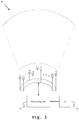
- the system 10 comprises a plurality of radar clusters 11 where each cluster further comprises a plurality of transmit antennas 21a, 21b, 21c and a plurality of receive antennas 22a, 22b, 22c, which are further illustrated along Fig. 2 .
- the system further comprises a processing unit 13 and a user interface 15.
- the plurality of radar clusters are arranged in an arching formation to cover a portion 11a, 11b, 11c of a potential aircraft fly-zone.
- the radar clusters 11 are for instance square shaped panels and are preferably stationary multistatic radar clusters. Other shapes for the clusters 11 are also viable in the consideration of manufacturing process complexity and costs.
- the processing unit 13 and the user interface 15 are interconnected by means of standard transmission lines, for instance coaxial cables, optical fibers and so on.
- the processing unit 13 comprises, preferably, a Field Programmable Gate Array (FPGA) to perform digital signal processing.
- FPGA Field Programmable Gate Array
- Fig. 2 a more detailed view of the first exemplary embodiment of the inventive system 10 for detecting aircraft signatures is illustrated.
- the internal components of radar clusters 11 and processing unit 13 are described in greater detail.
- the plurality of transmit antennas 21a, 21b, 21c and the plurality of receive antennas 22a, 22b, 22c are co-located within a radar cluster on a sparse antenna array.
- the sparse array formation allows a comprehensive digital beam-formation with the minimum number of antenna elements and advantageously can achieve the resolution of a conventional dense array with more elements.
- the radar components operate together as well as in proper time and hence the transmit antennas 21a, 21b, 21c are time synchronized and phase coherent with the receive antennas 22a, 22b, 22c.
- a simple coherent trigger generation is implemented by the processing unit 13 through its signal generation function 23.
- having phase coherent transmit and receive antennas further facilitate precise beam-formation.
- the processing unit 13 uses digital beam forming of the captured data through its digital beamforming function 24.
- the said captured data are essentially reflected transmit signals that are broadcasted sequentially or simultaneously from the plurality of transmit antennas 21a, 21b, 21c and are correspondingly received over the plurality of receive antennas 22a, 22b, 22c.
- the processing unit 13 performs phase adjustments of received data sets through its signal processing function 25 to increase the power of a particular beam in the potential aircraft fly-zone, as soon as the signal processing function 25 compiles a multiple received data sets. It is particularly advantageous that multiple receiving antennas 22a, 22b, 22c are utilized for beamforming since the potential noise contribution is effectively minimized by means of destructive interference.
- the processing unit 13 detects not only the bulk motion of the aircraft from the constant Doppler frequency shift but also micro-motions such as vibrations or rotations of a rotating part from a stationary aircraft by means of micro-Doppler analysis. It is further implemented that artificial intelligence methods are utilized to train the detection algorithm on both raw data and reconstructed images, which permits further provisions for automatic detection.
- some routed flights of any new drone can be used to extract the ground truth data and a user can either feed the information directly to the processing unit 13 or store them to the memory 26 via the user interface 15, from where the signal processing function 25 collects the information as per user instructions and compares with the detected results. In this manner, the automation of the artificial intelligence methods can be implemented with least effort.
- a second exemplary embodiment of the inventive system 30 for detecting aircraft signatures is illustrated.
- an arching formation of a plurality of multistatic transmit antennas 31a, 31b, 31c,...,31n and a plurality of multistatic receive antennas 32a, 32b, 32c,...,32n are implemented.
- the transmit antennas 31a, 31b, 31c,...,31n broadcast transmit signals one after another in a very quick successions to cover the potential aircraft fly-zone in a very small total time frame. In this manner, the complexity and cost are reduced in a large extend with a further reduction of antenna elements.
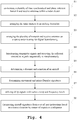
- a flow chart of an exemplary embodiment of the inventive method for detecting aircraft signatures is illustrated.
- a plurality of time synchronized and phase coherent transmit and receive antennas are co-located within a radar cluster.
- the radar clusters are arranged in an arching formation.
- the plurality of transmit and receive antennas are arranged on a sparse antenna array for digital beamforming.
- a distance and a motion of an aircraft are determined.
- a sixth step S6 movement signatures and micro-Doppler signatures of the aircraft are determined.
- a seventh step S7 chirp signals having various ramp and frequency levels are utilized.
- step S8 aircraft signatures are interpreted from a set of user instructions based on a known location of the said aircraft by means of cognitive intelligence.
- a signature can be any means to identify the aircraft or drone such as radar response pattern, Doppler response, rotor radar response or even a number plate.
Landscapes
- Engineering & Computer Science (AREA)
- Radar, Positioning & Navigation (AREA)
- Remote Sensing (AREA)
- Physics & Mathematics (AREA)
- Computer Networks & Wireless Communication (AREA)
- General Physics & Mathematics (AREA)
- Artificial Intelligence (AREA)
- Evolutionary Computation (AREA)
- Electromagnetism (AREA)
- Radar Systems Or Details Thereof (AREA)
Abstract
Description
- The invention relates to a system and a corresponding method for detecting aircraft signatures, especially for detecting autonomous drones with silent operation as well as standard detection in restricted visibility.
- With an increasing application of drones in the industrial and private sectors, there is a growing need to provide reliable detection schemes for preventing intrusion, industrial espionage and the like. Generally, radars along with multiple sensors (optical, sonar, infrared etc.) are used in a detection system where multiple sensor data fusion is performed. However, such detection system fails to effectively identify the drone signatures (identification of the drone) in extreme operating environments, for instance under bad weather conditions when optical and infrared systems have limited visibility. In addition, the radar sensors are mostly mechanical range radars with limited signal analysis capabilities. As a counter measure, multistatic detection technique is introduced in radar detection systems to facilitate further signal analysis competency by means of beamforming. Disadvantageously, the effective beam-formation requires a large number of antenna elements on the antenna array, which leads to a cost-intensive system.
- For example,
US 2017/0285158 A1 demonstrates multistatic drone detection in a radar system using beamforming where a three-dimensional field of surveillance having a volume exceeding one cubic kilometer is successively monitored. Accordingly, it is the object to provide a system and a corresponding method for detecting aircraft signatures, particularly for robust detection of drone signatures in a cost effective manner. - The above object is solved by the features of the independent claims. Further developments are comprised by the dependent claims.
- According to a first aspect of the invention, a radar system for detecting aircraft signatures is provided. The system comprises a plurality of radar clusters where each radar cluster further comprises a plurality of transmit antennas and a plurality of receive antennas. In this context, the plurality of transmit antennas and the plurality of receive antennas are co-located within each radar cluster. Advantageously, the co-located antennas deliver a confined structure so that the target radar cross sections observed by the antennas are nearly identical and hence improve the spatial resolution. In addition, the plurality of transmit and receive antennas form a plurality of radar resolution cells that significantly extend the radar coverage area.
- Furthermore, the plurality of transmit antennas are time synchronized and/or phase coherent with the plurality of receive antennas. Preferably the transmit antennas and the receive antennas are time synchronized and/or are coherent in phase, where the time synchronization allows sufficient spatial diversity for the antennas and having phase coherent transmit and receive antennas further allows precision beamforming. Particularly, the phase coherence between the transmit antennas and the receive antennas facilitates more comprehensive beam-formation and hence utilizes fewer array elements, which leads to a robust detection system with a substantial cost reduction. According to a first preferred implementation form of said first aspect of the invention, the plurality of radar clusters are preferably stationary multistatic radar clusters. Advantageously, the antenna aperture dimension limitations of classical monostatic radar are overcome by means of distributed antennas for transmission and reception, which further enhance the robustness of the detection system.
- According to a second preferred implementation form of said first aspect of the invention, the plurality of radar clusters are arranged in an arching formation to cover a portion of a potential aircraft fly-zone. Advantageously, the radar coverage area for detection is further extended.
- According to a third preferred implementation form of said first aspect of the invention, the plurality of transmit antennas and the plurality of receive antennas are co-located on an antenna array, preferably on a sparse antenna array for digital beamforming. Advantageously, sparse arrays elements increase the resolution as the same amount of elements can be distributed over a larger antenna aperture. This effectively reduces the hardware costs since less elements can achieve the resolution of a conventional dense array with more elements.
- According to a further preferred implementation form of said first aspect of the invention, the plurality of transmit antennas are configured to broadcast transmitter signals sequentially or simultaneously. In addition, the plurality of receive antennas are configured to receive the reflected transmitter signals sequentially or simultaneously. In this context, the simultaneous reception enables optimum use of the broadcasted transmitter signals whereas the sequential reception minimizes the hardware requirements. Advantageously, the system provides sufficient flexibility for detecting signatures on a case-by-case basis.
- According to a further preferred implementation form of said first aspect of the invention, the system further comprises a processing unit, configured to determine a distance of an aircraft corresponding to a delay of the broadcasted and the reflected transmitter signals. In addition, the processing unit is further configured to detect a motion of the aircraft by analyzing Doppler shifts acquired from the reflected transmitter signals. In this context, the processing unit is configured to identify aircraft signatures to detect aircraft locations by determining movement signatures corresponding to the motion of the aircraft if the aircraft is moving. It is further advantageous that the processing unit is configured to identify aircraft signatures to detect aircraft locations by determining micro-Doppler signatures corresponding to micro-Doppler analysis of phase shifts if the aircraft is stationary. Hence, the micro-Doppler analysis of phase shifts inside the signal spectrum improves the detection sensitivity significantly since a drone even in stationary condition still puts off micro-Doppler signatures from its rotors.
- According to a further preferred implementation form of said first aspect of the invention, the processing unit is further configured to utilize multiple chirp signals with a range of ramps and frequency levels to avoid aliasing at low frequencies and to obtain higher resolution. In this manner, aliasing in initial low frequency chirps is advantageously avoided, and by following such chirps with different higher frequency chirps, a higher resolution on any found objects from the first chirp is obtained.
- According to a further preferred implementation form of said first aspect of the invention, the processing unit is further configured to interpret aircraft signatures from a set of user instructions based on a known location of the aircraft by means of cognitive intelligence. In this manner, artificial intelligence methods are used to train the detection algorithm on both raw data and reconstructed images to facilitate automated detection.
- According to a further preferred implementation form of said first aspect of the invention, the system further comprises a plurality of multistatic transmit antennas and a plurality of multistatic receive antennas which are arranged in an arching formation. In this context, the plurality of transmit antennas are configured to broadcast in quick successions in order to cover the potential aircraft fly-zone in a very small total time frame. Advantageously, an effective detection with a few number of antenna elements can be achieved.
- According to a further preferred implementation form of said first aspect of the invention, the aircraft signatures to be detected are drone signatures. Advantageously, a robust detection system for recognizing drone signatures is provided.
- According to a second aspect of the invention, a method for detecting aircraft signatures in a radar system comprising a plurality of radar clusters each comprising a plurality of transmit antennas and a plurality of receive antennas is provided. The method performs the step of co-locating the plurality of transmit antennas and the plurality of receive antennas within each radar cluster. In this context, the plurality of transmit antennas are time synchronized and/or phase coherent with the plurality of receive antennas. It is particularly advantageous that the transmit antennas and the receive antennas are coherent in phase, which facilitates more comprehensive beam-formation and hence utilizes fewer array elements, eventually leads to a robust detection system with a substantial cost reduction.
- According to a first preferred implementation form of said second aspect of the invention, the method further comprises the step of arranging the plurality of radar clusters in an arching formation to cover a portion of a potential aircraft fly-zone. Advantageously, the radar coverage area for detection is significantly extended.
- According to a second preferred implementation form of said second aspect of the invention, the method further comprises the step of co-locating the plurality of transmit antennas and the plurality of receive antennas on an antenna array, preferably on a sparse antenna array for digital beamforming. This effectively reduce the hardware costs since by means of sparse array, less elements can achieve the resolution of a conventional dense array with more elements.
- According to a third preferred implementation form of said second aspect of the invention, the method further comprises the steps of broadcasting transmitter signals sequentially or simultaneously and receiving the reflected transmitter signals sequentially or simultaneously. In this context, the simultaneous reception enables optimum use of the broadcasted transmitter signals whereas the sequential reception minimizes the hardware requirements and hence sufficient flexibility is provided for detecting signatures on a case-by-case basis.
- According to a further preferred implementation form of said second aspect of the invention, the method further comprises the steps of determining a distance of an aircraft corresponding to a delay of the broadcasted and the reflected transmitter signals and detecting a motion of the aircraft by analyzing Doppler shifts acquired from the reflected transmitter signals. Further advantageously the method comprises the steps of determining movement signatures corresponding to the motion of the aircraft if the aircraft is moving and determining micro-Doppler signatures corresponding to micro-Doppler analysis of phase shifts if the aircraft is stationary. Hence, the micro-Doppler analysis of phase shifts inside the signal spectrum improves the detection sensitivity significantly since a drone even in stationary condition still puts off micro-Doppler signatures from its rotors.
- According to a further preferred implementation form of said second aspect of the invention, the method further comprises the step of utilizing multiple chirp signals with a range of ramps and frequency levels to avoid aliasing at low frequencies and to obtain higher resolution. In this manner, aliasing in initial low frequency chirps is advantageously avoided and by following such chirps with different higher frequency chirps, a higher resolution on any found objects from the first chirp is obtained.
- According to a further preferred implementation form of said second aspect of the invention, the method further comprises the step of interpreting aircraft signatures from a set of user instructions based on a known location of the aircraft by means of cognitive intelligence. Advantageously, artificial intelligence methods are used to train the detection algorithm on both raw data and reconstructed images to facilitate automated detection.
- Exemplary embodiments of the invention are now further explained with respect to the drawings by way of example only, and not for limitation. In the drawings:
- Fig. 1
- shows a first exemplary embodiment of the system according to the first aspect of the invention,
- Fig. 2
- shows a more detailed view of the first exemplary embodiment of the system according to the first aspect of the invention,
- Fig. 3
- shows a second exemplary embodiment of the system according to the first aspect of the invention, and
- Fig. 4
- shows a flow chart of an exemplary embodiment of the method according to the second aspect of the invention.
- First, we demonstrate the general construction and function of a first exemplary embodiment of the system of the first aspect of the invention, along
Fig. 1 . AlongFig. 2 , the first exemplary embodiment of the system according to the first aspect of the invention is described in detail. After that, alongFig. 3 , we demonstrate the general construction and function of a second exemplary embodiment of the system of the first aspect of the invention. Finally, with regard to the flow chart ofFig. 3 , an exemplary embodiment of the method according to the second aspect of the invention is described. - Reference will now be made in detail to the embodiments of the present invention, examples of which are illustrated in the accompanying drawings. Similar entities and reference numbers in different figures have been partially omitted. However, the following embodiments of the present invention may be variously modified and the range of the present invention is not limited by the following embodiments.
- In
Fig. 1 , a first exemplary embodiment of theinventive system 10 for detecting aircraft signatures is illustrated. Thesystem 10 comprises a plurality ofradar clusters 11 where each cluster further comprises a plurality of transmitantennas antennas Fig. 2 . The system further comprises aprocessing unit 13 and auser interface 15. The plurality of radar clusters are arranged in an arching formation to cover aportion radar clusters 11 are for instance square shaped panels and are preferably stationary multistatic radar clusters. Other shapes for theclusters 11 are also viable in the consideration of manufacturing process complexity and costs. Theprocessing unit 13 and theuser interface 15 are interconnected by means of standard transmission lines, for instance coaxial cables, optical fibers and so on. Theprocessing unit 13 comprises, preferably, a Field Programmable Gate Array (FPGA) to perform digital signal processing. - In
Fig. 2 , a more detailed view of the first exemplary embodiment of theinventive system 10 for detecting aircraft signatures is illustrated. Here, the internal components ofradar clusters 11 andprocessing unit 13 are described in greater detail. - In this context, the plurality of transmit
antennas antennas antennas antennas processing unit 13 through itssignal generation function 23. In addition to time synchronization, having phase coherent transmit and receive antennas further facilitate precise beam-formation. - Moreover, the
processing unit 13 uses digital beam forming of the captured data through itsdigital beamforming function 24. The said captured data are essentially reflected transmit signals that are broadcasted sequentially or simultaneously from the plurality of transmitantennas antennas processing unit 13 performs phase adjustments of received data sets through itssignal processing function 25 to increase the power of a particular beam in the potential aircraft fly-zone, as soon as thesignal processing function 25 compiles a multiple received data sets. It is particularly advantageous that multiple receivingantennas - Further advantageously, the
processing unit 13 detects not only the bulk motion of the aircraft from the constant Doppler frequency shift but also micro-motions such as vibrations or rotations of a rotating part from a stationary aircraft by means of micro-Doppler analysis. It is further implemented that artificial intelligence methods are utilized to train the detection algorithm on both raw data and reconstructed images, which permits further provisions for automatic detection. In this context, some routed flights of any new drone can be used to extract the ground truth data and a user can either feed the information directly to theprocessing unit 13 or store them to thememory 26 via theuser interface 15, from where thesignal processing function 25 collects the information as per user instructions and compares with the detected results. In this manner, the automation of the artificial intelligence methods can be implemented with least effort. - In
Fig. 3 , a second exemplary embodiment of the inventive system 30 for detecting aircraft signatures is illustrated. In this context, instead of the multiple radar clusters an arching formation of a plurality of multistatic transmitantennas antennas antennas - In
Fig. 4 , a flow chart of an exemplary embodiment of the inventive method for detecting aircraft signatures is illustrated. In a first step S1, a plurality of time synchronized and phase coherent transmit and receive antennas are co-located within a radar cluster. In a second step S2, the radar clusters are arranged in an arching formation. In a third step S3, the plurality of transmit and receive antennas are arranged on a sparse antenna array for digital beamforming. - Furthermore, in a fourth step S4, transmitter signals are broadcasted sequentially or simultaneously and the reflected transmitter signals are received sequentially or simultaneously. In a fifth step S5, a distance and a motion of an aircraft are determined.
- Moreover, in a sixth step S6, movement signatures and micro-Doppler signatures of the aircraft are determined. In a seventh step S7, chirp signals having various ramp and frequency levels are utilized.
- Finally, in an eighth step S8, aircraft signatures are interpreted from a set of user instructions based on a known location of the said aircraft by means of cognitive intelligence.
- Within this application a signature can be any means to identify the aircraft or drone such as radar response pattern, Doppler response, rotor radar response or even a number plate.
- While various embodiments of the present invention have been described above, it should be understood that they have been presented by way of example only, and not limitation. Numerous changes to the disclosed embodiments can be made in accordance with the disclosure herein without departing from the spirit or scope of the invention. Thus, the breadth and scope of the present invention should not be limited by any of the above described embodiments. Rather, the scope of the invention should be defined in accordance with the following claims and their equivalents.
- Although the invention has been illustrated and described with respect to one or more implementations, equivalent alterations and modifications will occur to others skilled in the art upon the reading and understanding of this specification and the annexed drawings. In addition, while a particular feature of the invention may have been disclosed with respect to only one of several implementations, such feature may be combined with one or more other features of the other implementations as may be desired and advantageous for any given or particular application.
Claims (20)
- A radar system (10,30) for detecting aircraft signatures comprises a plurality of radar clusters (11) each comprising:- a plurality of transmit antennas (21a,21b,21c,21n), and- a plurality of receive antennas (22a,22b,22c,22n), wherein the plurality of transmit antennas (21a,21b,21c,21n) and the plurality of receive antennas (22a, 22b,22c,22n) are co-located within each radar cluster (11), andwherein the plurality of transmit antennas (21a,21b, 21c, 21n) are time synchronized and/or phase coherent with the plurality of receive antennas (22a,22b,22c,22n).
- The system according to claim 1,
wherein the plurality of radar clusters (11) are preferably stationary multistatic radar clusters. - The system according to claim 1 or 2,
wherein the plurality of radar clusters (11) are arranged in an arching formation to cover a portion (11a,11b,11c) of a potential aircraft fly-zone. - The system according to any of claims 1 to 3,
wherein the plurality of transmit antennas (21a,21b,21c, 21n) and the plurality of receive antennas (22a, 22b,22c,22n) are co-located on an antenna array, preferably on a sparse antenna array for digital beamforming. - The system according to any of claims 1 to 4,
wherein the plurality of transmit antennas (21a,21b,21c,21n) are configured to broadcast transmitter signals sequentially or simultaneously, and
wherein the plurality of receive antennas (22a,22b,22c,22n) are configured to receive the reflected transmitter signals sequentially or simultaneously. - The system according to any of claims 1 to 5,
wherein the system further comprises a processing unit (13), configured to determine a distance of an aircraft corresponding to a delay of the broadcasted and the reflected transmitter signals, and
wherein the processing unit (13) is further configured to detect a motion of the aircraft by analyzing Doppler shifts acquired from the reflected transmitter signals. - The system according to claim 6,
wherein the processing unit (13) is further configured to identify aircraft signatures to detect aircraft locations by- determining movement signatures corresponding to the motion of the aircraft if the aircraft is moving, and- determining micro-Doppler signatures corresponding to micro-Doppler analysis of phase shifts if the aircraft is stationary. - The system according to claim 6 or 7,
wherein the processing unit (13) is further configured to utilize multiple chirp signals with a range of ramps and frequency levels to avoid aliasing at low frequencies and to obtain higher resolution. - The system according to any of claims 6 to 8,
wherein the processing unit (13) is further configured to interpret aircraft signatures from a set of user instructions based on a known location of the aircraft by means of cognitive intelligence. - The system according to any of claims 1 to 9,
wherein the system further comprises a plurality of multistatic transmit antennas (31a, 31b, 31c, ... 31n) and a plurality of multistatic receive antennas (32a, 32b, 32c, ... 32n) which are arranged in an arching formation. - The system according to claim 10,
wherein the plurality of transmit antennas (31a, 31b, 31c, ... 31n)are configured to broadcast in quick successions in order to cover the potential aircraft fly-zone in a very small total time frame. - The system according to any of claims 1 to 11, wherein the aircraft signatures to be detected are drone signatures.
- A method for detecting aircraft signatures in a radar system (10,30) comprising a plurality of radar clusters (11) each comprising a plurality of transmit antennas (21a,21b,21n) and a plurality of receive antennas (22a,22b,22n) performing:- co-locating the plurality of transmit antennas (21a,21b,21n) and the plurality of receive antennas (22a,22b,22n) within each radar cluster (11),wherein the plurality of transmit antennas (21a,21b,21n) are time synchronized and/or phase coherent with the plurality of receive antennas (22a,22b,22n).
- The method according to claim 13,
wherein the method further comprises the step of arranging the plurality of radar clusters (13) in an arching formation to cover a portion (11a,11b,11c) of a potential aircraft fly-zone. - The method according to claim 13 or 14,
wherein the method further comprises the step of co-locating the plurality of transmit antennas (21a,21b,21n) and the plurality of receive antennas (22a,22b,22c) on an antenna array, preferably on a sparse antenna array for digital beamforming. - The method according to any of claims 13 to 15, wherein the method further comprises the steps of:- broadcasting transmitter signals sequentially or simultaneously, and- receiving the reflected transmitter signals sequentially or simultaneously.
- The method according to any of claims 13 to 16, wherein the method further comprises the steps of:- determining a distance of an aircraft corresponding to a delay of the broadcasted and the reflected transmitter signals, and- detecting a motion of the aircraft by analyzing Doppler shifts acquired from the reflected transmitter signals.
- The method according to any of claims 13 to 17, wherein the method further comprises the steps of:- determining movement signatures corresponding to the motion of the aircraft if the aircraft is moving, and- determining micro-Doppler signatures corresponding to micro-Doppler analysis of phase shifts if the aircraft is stationary.
- The method according to any of claims 13 to 18, wherein the method further comprises the step of utilizing multiple chirp signals with a range of ramps and frequency levels to avoid aliasing at low frequencies and to obtain higher resolution.
- The method according to any of claims 13 to 19, wherein the method further comprises the step of interpreting aircraft signatures from a set of user instructions based on a known location of the aircraft by means of cognitive intelligence.
Applications Claiming Priority (1)
| Application Number | Priority Date | Filing Date | Title |
|---|---|---|---|
| US16/292,472 US11656335B2 (en) | 2019-03-05 | 2019-03-05 | System and method for detecting aircraft signatures |
Publications (1)
| Publication Number | Publication Date |
|---|---|
| EP3705909A1 true EP3705909A1 (en) | 2020-09-09 |
Family
ID=66102909
Family Applications (1)
| Application Number | Title | Priority Date | Filing Date |
|---|---|---|---|
| EP19168026.3A Withdrawn EP3705909A1 (en) | 2019-03-05 | 2019-04-09 | System and method for detecting aircraft signatures |
Country Status (2)
| Country | Link |
|---|---|
| US (1) | US11656335B2 (en) |
| EP (1) | EP3705909A1 (en) |
Families Citing this family (8)
| Publication number | Priority date | Publication date | Assignee | Title |
|---|---|---|---|---|
| US11520030B2 (en) | 2019-03-18 | 2022-12-06 | Nxp Usa, Inc. | High resolution automotive radar system with forward and backward difference co-array processing |
| US11092683B2 (en) * | 2019-03-18 | 2021-08-17 | Nxp Usa, Inc. | Distributed aperture automotive radar system with alternating master radar devices |
| US11269049B2 (en) | 2019-03-18 | 2022-03-08 | Nxp Usa, Inc. | Distributed aperture automotive radar system |
| US12164057B2 (en) * | 2019-12-16 | 2024-12-10 | Ay Dee Kay Llc | Calibrating array antennas based on signal energy distribution as a function of angle |
| US11888554B2 (en) | 2020-09-23 | 2024-01-30 | Nxp Usa, Inc. | Automotive MIMO radar system using efficient difference co-array processor |
| WO2022139844A1 (en) * | 2020-12-24 | 2022-06-30 | Intel Corporation | Radar apparatus, system, and method |
| GB2606554A (en) * | 2021-05-13 | 2022-11-16 | Secr Defence | A drone detection device and method thereof |
| CN116973865B (en) * | 2023-06-13 | 2026-08-07 | 深圳市大数据研究院 | A Space-Based Two-Level Distributed Robust Beam Synthesis Method |
Citations (5)
| Publication number | Priority date | Publication date | Assignee | Title |
|---|---|---|---|---|
| US20110187581A1 (en) * | 2010-02-02 | 2011-08-04 | Thales | Radar Device for Detecting or Tracking Aerial Targets Fitted to an Aircraft |
| US20170285158A1 (en) | 2013-08-28 | 2017-10-05 | Max Peter HALBERT | Radar system and associated apparatus and methods |
| WO2017207716A1 (en) * | 2016-06-02 | 2017-12-07 | Qinetiq Limited | Radar target detection system and method |
| CN107450065A (en) * | 2017-08-07 | 2017-12-08 | 中国民航大学 | A kind of inexpensive SUAV surveillance radar |
| EP3367126A1 (en) * | 2017-02-28 | 2018-08-29 | Honeywell International Inc. | Weather radar detection of objects |
Family Cites Families (33)
| Publication number | Priority date | Publication date | Assignee | Title |
|---|---|---|---|---|
| GB1529381A (en) | 1976-12-29 | 1978-10-18 | Decca Ltd | Aircraft detection |
| GB2242589B (en) | 1984-07-12 | 1992-03-25 | Decca Ltd | Mobile radar apparatus |
| US5539411A (en) * | 1995-11-17 | 1996-07-23 | The United States Of America As Represented By The Secretary Of The Navy | Multistatic radar signature measurement apparatus |
| JP3672212B2 (en) | 1997-10-24 | 2005-07-20 | 三菱電機株式会社 | Synthetic aperture radar equipment |
| FR2801109B1 (en) | 1999-11-12 | 2001-12-28 | Onera (Off Nat Aerospatiale) | MULTISTATIC PASSIVE RADAR FOR LOCATION OF TURNING AIRCRAFT |
| US6703968B2 (en) * | 2001-05-04 | 2004-03-09 | Lockheed Martin Corporation | System and method for mitigating co-channel interference in passive coherent location applications |
| JP3753121B2 (en) | 2002-10-10 | 2006-03-08 | 三菱電機株式会社 | Radar apparatus and radar system |
| US6653970B1 (en) | 2002-11-12 | 2003-11-25 | The United States Of America As Represented By The Secretary Of The Air Force | Multi-static UAV radar system for mode-adaptive propagation channels with obscured targets |
| US7280068B2 (en) * | 2005-07-14 | 2007-10-09 | Agilent Technologies, Inc. | System and method for microwave imaging with suppressed sidelobes using a sparse antenna array |
| KR100753819B1 (en) | 2005-12-09 | 2007-08-31 | 한국전자통신연구원 | Multistatic Radar Observation System and Its Method |
| FR2927423B1 (en) | 2008-02-12 | 2011-06-17 | Thales Sa | THREE-DIMENSIONAL RADIOELECTRIC LOCATION METHOD IN MULTISTATIC OPERATION |
| FR2942884B1 (en) | 2009-03-09 | 2011-04-01 | Onera (Off Nat Aerospatiale) | MULTISTATIC AIRPORT SURVEILLANCE RADAR SYSTEM |
| FR2956907B1 (en) | 2010-02-26 | 2012-09-21 | Thales Sa | MULTISTATIC RADAR SYSTEM FOR PRECISE MEASUREMENT OF ALTITUDE |
| WO2012175819A1 (en) | 2011-06-20 | 2012-12-27 | Thales | Multistatic radar system for precisely measuring altitude |
| FR3006060B1 (en) | 2013-05-24 | 2016-12-02 | Thales Sa | METHOD FOR LOCATING A TARGET AND MULTISTATIC RADAR SYSTEM FOR IMPLEMENTING SUCH A METHOD |
| US9442188B2 (en) * | 2014-03-14 | 2016-09-13 | Codar Ocean Sensors, Ltd. | Negative pseudo-range processing with multi-static FMCW radars |
| JP6584825B2 (en) | 2015-05-18 | 2019-10-02 | 株式会社東芝 | Multistatic radar system and synchronous monitoring method |
| US11199618B2 (en) * | 2016-06-17 | 2021-12-14 | Apple Inc. | Radar antenna array |
| US10690750B2 (en) * | 2017-01-24 | 2020-06-23 | GM Global Technology Operations LLC | Synchronization of spatially distributed radar |
| DE102017110063A1 (en) * | 2017-03-02 | 2018-09-06 | Friedrich-Alexander-Universität Erlangen-Nürnberg | Method and device for environment detection |
| US10775498B2 (en) * | 2017-03-13 | 2020-09-15 | Honeywell International Inc. | Methods for a multi-function electronically steered weather radar |
| CN106932776B (en) | 2017-03-24 | 2019-07-26 | 北京理工大学 | One kind being based on navigation satellite multistatic SARS large scene imaging method |
| CN207096444U (en) | 2017-06-19 | 2018-03-13 | 韦震 | Low slow small unmanned aerial vehicle flight path measuring system |
| JP2020513122A (en) * | 2017-07-06 | 2020-04-30 | トップ フライト テクノロジーズ, インコーポレイテッド | Navigation system for drones |
| EP3467449B1 (en) * | 2017-10-06 | 2020-07-08 | VEGA Grieshaber KG | Radar fill level measuring device with high frequency amplifier |
| US11536828B2 (en) * | 2018-02-21 | 2022-12-27 | Board Of Trustees Of Michigan State University | Methods and systems for distributed radar imaging |
| US20200083979A1 (en) * | 2018-09-06 | 2020-03-12 | Airspace Systems, Inc. | Unmanned aerial vehicle jammer |
| US20200158822A1 (en) * | 2018-09-06 | 2020-05-21 | Airspace Systems, Inc. | Unmanned aerial vehicle radar detection |
| JP2022502663A (en) * | 2018-10-02 | 2022-01-11 | フォルテム テクノロジーズ,インコーポレイテッド | Systems and methods for classifying drones and objects |
| US20200162489A1 (en) * | 2018-11-16 | 2020-05-21 | Airspace Systems, Inc. | Security event detection and threat assessment |
| US11448754B2 (en) * | 2018-11-20 | 2022-09-20 | KMB Telematics, Inc. | Object sensing from a potentially moving frame of reference with virtual apertures formed from sparse antenna arrays |
| US11054498B2 (en) * | 2019-01-22 | 2021-07-06 | Nxp Usa, Inc. | System and method of configuring an external radar device through high speed reverse data transmission |
| US11175393B2 (en) * | 2019-02-08 | 2021-11-16 | Koko Home, Inc. | System and method for processing multi-directional ultra wide band and frequency modulated continuous wave wireless backscattered signals |
-
2019
- 2019-03-05 US US16/292,472 patent/US11656335B2/en active Active
- 2019-04-09 EP EP19168026.3A patent/EP3705909A1/en not_active Withdrawn
Patent Citations (5)
| Publication number | Priority date | Publication date | Assignee | Title |
|---|---|---|---|---|
| US20110187581A1 (en) * | 2010-02-02 | 2011-08-04 | Thales | Radar Device for Detecting or Tracking Aerial Targets Fitted to an Aircraft |
| US20170285158A1 (en) | 2013-08-28 | 2017-10-05 | Max Peter HALBERT | Radar system and associated apparatus and methods |
| WO2017207716A1 (en) * | 2016-06-02 | 2017-12-07 | Qinetiq Limited | Radar target detection system and method |
| EP3367126A1 (en) * | 2017-02-28 | 2018-08-29 | Honeywell International Inc. | Weather radar detection of objects |
| CN107450065A (en) * | 2017-08-07 | 2017-12-08 | 中国民航大学 | A kind of inexpensive SUAV surveillance radar |
Non-Patent Citations (2)
| Title |
|---|
| HARMAN STEPHEN: "A comparison of staring radars with scanning radars for UAV detection: Introducing the Alarm(TM) staring radar", 2015 EUROPEAN RADAR CONFERENCE (EURAD), EUMA, 9 September 2015 (2015-09-09), pages 185 - 188, XP032824534, DOI: 10.1109/EURAD.2015.7346268 * |
| MOLCHANOV P ET AL: "Classification of small UAVs and birds by micro-Doppler signatures", 2013 EUROPEAN RADAR CONFERENCE, EMA, 9 October 2013 (2013-10-09), pages 172 - 175, XP032533667 * |
Also Published As
| Publication number | Publication date |
|---|---|
| US11656335B2 (en) | 2023-05-23 |
| US20200284877A1 (en) | 2020-09-10 |
Similar Documents
| Publication | Publication Date | Title |
|---|---|---|
| US11656335B2 (en) | System and method for detecting aircraft signatures | |
| JP6920198B2 (en) | An imaging radar sensor that measures objects in the vertical direction by forming a digital beam in the horizontal direction and comparing the phases of offset transmitters. | |
| CA2595667C (en) | Device & method for 3d height-finding avian radar | |
| US8009080B2 (en) | Weather radar and weather observation method | |
| US10877130B2 (en) | Drone detection radar | |
| US9190717B2 (en) | Radar sensor | |
| CN113050082A (en) | Method and apparatus for processing radar signals | |
| US9696419B2 (en) | Marine radar based on cylindrical array antennas with other applications | |
| JP6062440B2 (en) | Angular resolution radar sensor | |
| US20180313952A1 (en) | Method and device for tracking objects, in particular moving objects, in the three-dimensional space of imaging radar sensors | |
| Jahangir et al. | L-band staring radar performance against micro-drones | |
| CN112904329A (en) | Target monitoring system and method based on millimeter wave radar | |
| CN113030946A (en) | Secondary radar detection method, apparatus, device, system, medium, and program product | |
| Golubović et al. | An Introduction to Vessel Tracking in HFSWRs Based on a High-Resolution Range-Doppler Map: Some Preliminary Results and Challenges | |
| Griffiths | Developments in bistatic and networked radar | |
| Galati et al. | Time for a change in phased array radar architectures-Part II: the d-Radar | |
| JP4754292B2 (en) | Radar equipment | |
| JP2005062058A (en) | Search radar equipment | |
| Gilpin et al. | Real-Time Multiple Input Multiple Output (MIMO) Radar Using Software Defined Radio | |
| Sivagnanam et al. | Improved azimuth accuracy for a digital beamforming perimeter surveillance radar | |
| Del-Rey-Maestre et al. | DoA estimation based on a ULA of commercial antennas in semi-urban passive radar scenario | |
| van Rossum et al. | Space-Time Block Coding waveform for suppression of jamming in a MIMO radar | |
| CA3033676C (en) | Novel automotive radar using 3d printed luneburg lens | |
| Brenner et al. | Multiband Radar Modelling | |
| US20250244447A1 (en) | Signal processing method, device, and storage medium |
Legal Events
| Date | Code | Title | Description |
|---|---|---|---|
| PUAI | Public reference made under article 153(3) epc to a published international application that has entered the european phase |
Free format text: ORIGINAL CODE: 0009012 |
|
| STAA | Information on the status of an ep patent application or granted ep patent |
Free format text: STATUS: REQUEST FOR EXAMINATION WAS MADE |
|
| 17P | Request for examination filed |
Effective date: 20200224 |
|
| AK | Designated contracting states |
Kind code of ref document: A1 Designated state(s): AL AT BE BG CH CY CZ DE DK EE ES FI FR GB GR HR HU IE IS IT LI LT LU LV MC MK MT NL NO PL PT RO RS SE SI SK SM TR |
|
| AX | Request for extension of the european patent |
Extension state: BA ME |
|
| STAA | Information on the status of an ep patent application or granted ep patent |
Free format text: STATUS: EXAMINATION IS IN PROGRESS |
|
| 17Q | First examination report despatched |
Effective date: 20210715 |
|
| P01 | Opt-out of the competence of the unified patent court (upc) registered |
Effective date: 20230525 |
|
| STAA | Information on the status of an ep patent application or granted ep patent |
Free format text: STATUS: THE APPLICATION IS DEEMED TO BE WITHDRAWN |
|
| 18D | Application deemed to be withdrawn |
Effective date: 20251003 |