EP3705837B1 - Schusswaffe, mit einem einen lauf tragenden schaft - Google Patents
Schusswaffe, mit einem einen lauf tragenden schaft Download PDFInfo
- Publication number
- EP3705837B1 EP3705837B1 EP20161940.0A EP20161940A EP3705837B1 EP 3705837 B1 EP3705837 B1 EP 3705837B1 EP 20161940 A EP20161940 A EP 20161940A EP 3705837 B1 EP3705837 B1 EP 3705837B1
- Authority
- EP
- European Patent Office
- Prior art keywords
- stock
- barrel
- gaps
- firearm
- filled
- Prior art date
- Legal status (The legal status is an assumption and is not a legal conclusion. Google has not performed a legal analysis and makes no representation as to the accuracy of the status listed.)
- Active
Links
Images




Classifications
-
- F—MECHANICAL ENGINEERING; LIGHTING; HEATING; WEAPONS; BLASTING
- F41—WEAPONS
- F41C—SMALLARMS, e.g. PISTOLS, RIFLES; ACCESSORIES THEREFOR
- F41C23/00—Butts; Butt plates; Stocks
- F41C23/16—Forestocks; Handgrips; Hand guards
-
- F—MECHANICAL ENGINEERING; LIGHTING; HEATING; WEAPONS; BLASTING
- F41—WEAPONS
- F41A—FUNCTIONAL FEATURES OR DETAILS COMMON TO BOTH SMALLARMS AND ORDNANCE, e.g. CANNONS; MOUNTINGS FOR SMALLARMS OR ORDNANCE
- F41A21/00—Barrels; Gun tubes; Muzzle attachments; Barrel mounting means
- F41A21/48—Barrel mounting means, e.g. releasable mountings for replaceable barrels
-
- F—MECHANICAL ENGINEERING; LIGHTING; HEATING; WEAPONS; BLASTING
- F41—WEAPONS
- F41C—SMALLARMS, e.g. PISTOLS, RIFLES; ACCESSORIES THEREFOR
- F41C23/00—Butts; Butt plates; Stocks
-
- F—MECHANICAL ENGINEERING; LIGHTING; HEATING; WEAPONS; BLASTING
- F41—WEAPONS
- F41C—SMALLARMS, e.g. PISTOLS, RIFLES; ACCESSORIES THEREFOR
- F41C23/00—Butts; Butt plates; Stocks
- F41C23/18—Butts; Butt plates; Stocks characterised by the material used
Definitions
- the invention relates to a firearm with a stock carrying a system and a barrel associated with this system, as well as a method for producing the same.
- the object of the invention is to provide an improved firearm with a secure, play-free system, stock and barrel as well as a method for their production.
- a firearm is proposed with a stock carrying a system and a barrel associated with this system, which is characterized in that the stock is pre-shaped in a defined manner and forms support areas for the system and the barrel associated with this system, wherein play between the stock and the system and/or the barrel is avoided by the fact that between the stock and System and/or at least partially the barrel associated with this system and/or at least partially around the support areas, gaps in the form of channels and/or recesses and/or elevations are provided which are filled with a material which is initially fluid and then solidifies and fits snugly against the gaps.
- a preferred embodiment of the invention provides that the material is filled through at least one inlet channel provided for this purpose from the outside through the shaft into the spaces between the shaft and/or system and/or the barrel associated therewith.
- a variant of the invention provides that in addition to an inlet channel, at least one outlet opening is also provided for the material, for example in the form of resin for injection or vacuum infiltration.
- the elevations can also be designed adaptively in the form of honeycombs; where the system rests without bedding (gluing), the honeycombs are designed larger.
- the shaft is advantageously made of a plastic material and the material is then made of a one-, two- or multi-component adhesive. This is a very durable material combination.
- the recesses are preferably formed as channels through cavities surrounding honeycomb structures.
- partition walls or channel separations can be provided in the shaft, which can be broken out in a defined manner beforehand to control the flow of material.
- a method for producing a firearm is proposed, according to which a support surface is arranged in a shaft, on the surface of which there are structures in the form of elevations, so that gaps in the form of channels and/or recesses are provided between them, wherein in a first method step a system of the firearm and/or a barrel associated with this system is arranged on the support surface, and in a second method step the gaps between the shaft or the support surface and the system and/or the barrel are filled with a material made of a one-, two- or multi-component adhesive, wherein the material is fed from the outside through the shaft into the gaps through at least one inlet channel provided for this purpose. is filled in, in the last process step the material solidifies to form a play-free connection that fits the system and/or the barrel and fills the gaps.
- Fig.1 a schematic plan view of a stock 4 according to the invention for a firearm 1 (see Fig.8 ) is shown.
- the shaft 4 is pre-shaped in a defined manner and forms support areas 41 for the system 2 and the barrel 3 associated with it.
- gaps 43 in the form of channels and/or recesses and/or elevations 44 between the shaft 4 and/or system 2 and/or at least partially the barrel 3 associated therewith and/or at least partially around the support areas 41, which are filled with a material that is initially fluid and then solidifies without play and fills the gaps (see the schematic representation according to Fig.8 ).
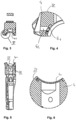
- Fig.2 shows the shaft from above
- the Fig.3 a cross-sectional view of the shaft Fig.2 in viewing direction III
- Fig.4 a detailed view of the cut Fig. 3
- Fig. 5 a cross-sectional view of the shaft Fig.2 in direction VI
- Fig.6 a cross-sectional view of the shaft Fig.2 in viewing direction III.
- the elevations 44 around the gaps 43 can be seen, which together also form part of the support areas 41.
- Fig.4 an inlet channel 42 for the material can be seen, which can be filled from the outside through the shaft 4 into the gaps 43 between the shaft 4 and/or system 2 and/or the barrel 3 associated therewith.
- Fig.7 shows a detailed view of area VII from Fig.2
- the structures that form the elevations 44 around the gaps 43 are clearly visible.
- the shaft 4 is made of a plastic material.
- the filling material is made of a one-, two- or multi-component adhesive.
- Fig.8 The process for manufacturing a firearm according to the invention is shown schematically in Fig.8 shown.
- a support surface 41 is arranged in the shaft, on the surface of which there are structures in the form of elevations 44 (see previous figure), so that between these gaps 43 in the form of channels and/or recesses are provided, wherein in a first method step a barrel 3 of the firearm 1 is arranged on the support surface 41, and in a second method step the gaps 43 between the shaft 4 or the support surface 41 and the barrel 3 are filled with a material made of a one-, two- or multi-component adhesive, wherein the material is introduced through at least one inlet channel 42 provided for this purpose from is filled from the outside through the shaft 4 into the gaps 43 between the shaft 4 and/or system 2 and/or the barrel 3 associated therewith; in the last process step, the material solidifies to form a play-free connection that fits snugly against the barrel and fills the gaps.
- the barrel is shown lifted off the stock (arrows). During the process, it would rest on the support areas and the remaining gaps between the system and/or stock and/or barrel would be filled. After hardening, the parts fit together without any play.
Landscapes
- Engineering & Computer Science (AREA)
- General Engineering & Computer Science (AREA)
- Aiming, Guidance, Guns With A Light Source, Armor, Camouflage, And Targets (AREA)
- Shielding Devices Or Components To Electric Or Magnetic Fields (AREA)
- Golf Clubs (AREA)
Description
- Die Erfindung betrifft eine Schusswaffe, mit einem ein System und einen diesem System zugeordneten Lauf tragenden Schaft, sowie ein Verfahren zur Herstellung derselben.
- Bei Schusswaffen insbesondere im Hochpräzisionsbereich wie bei Langwaffen beim Biathlon ist es oftmals so, dass die Schützen den Sitz von System und dem Lauf am Schaft als nicht optimal empfinden.
- So können Vibrationen und Klappern der Teile am Schaft auftreten.
- Eine beispielhafte Schusswaffe, wobei versucht wird dieses Problem zu beseitigen, wird in der
US 3,350,807 A beschrieben. - Aufgabe der Erfindung ist es eine verbesserte Schusswaffe mit sicher spielfrei sitzendem System, Schaft und Lauf sowie ein Verfahren zu deren Herstellung zur Verfügung zu stellen.
- Diese Aufgabe wird durch eine Schusswaffe, mit einem ein System und einen diesem System zugeordneten Lauf tragenden Schaft nach den Merkmalen des Anspruchs 1 und ein Verfahren zur Herstellung derselben nach den Merkmalen des Anspruchs 7 gelöst.
- Erfindungsgemäß ist eine Schusswaffe, mit einem ein System und einen diesem System zugeordneten Lauf tragenden Schaft, vorgeschlagen, die sich dadurch auszeichnet, dass der Schaft definiert vorgeformt ist und dem System und dem diesem System zugeordneten Lauf Auflagebereiche bildet, wobei ein Spiel zwischen Schaft und dem System und/oder dem Lauf dadurch vermieden ist, dass zwischen Schaft und System und/oder wenigstens teilweise dem diesem System zugeordneten Lauf und/oder wenigstens teilweise um die Auflagebereiche herum, Zwischenräume in Form von Kanälen und/oder Ausnehmungen und/oder Erhöhungen vorgesehen sind, welche mit einem zunächst fluiden und dann erstarrtem spielfrei anliegenden, die Zwischenräume füllendem Material ausgefüllt sind.
- Hierdurch ist auf besonders effektive Weise eine sichere spielfreie Verbindung des Laufs und/oder des Systems am Schaft gewährleistet. Jegliche kleinen ungewollten Abstände werden durch das später aushärtende Material gefüllt.
- Ein sicherer Formschluss zwischen System und Schaft ist gewährleistet.
- Eine bevorzugte Ausgestaltung der Erfindung sieht vor, das Material durch wenigstens einen hierzu vorgesehenen Eintrittskanal von außen durch den Schaft in die Zwischenräume zwischen Schaft und/oder System und/oder dem diesem zugeordneten Lauf eingefüllt ist.
- Eine Variante der Erfindung sieht vor, dass neben einem Eintrittskanal auch wenigstens eine Austrittsöffnung für das Material beispielsweise in Form von Harz für Einspritzen oder Vakkuum-Infiltration vorgesehen sind.
- Auch von Vorteil sind am Schaft vorgeformte 3D-gedruckte "Häutchen" zum Abdichten des Gussvolumens, diese können herausgebrochen werden an allen Außenkanten und am Magazinschacht.
- Ebenfalls können die Erhöhungen in Form von Waben adaptive gestaltet sein, dort wo ohne Bedding (Verklebung) das System aufliegt, sind die Waben größer gestaltet.
- Von Vorteil ist der Schaft aus einem Kunststoffmaterial gefertigt und dem folgend besteht das Material aus einem ein-, zwei- oder mehr Komponentenklebstoff. Dies ist eine sehr haltbare Stoffkombination.
- Die Ausnehmungen sind bevorzugterweise als Kanäle durch um Wabenstrukturen liegende Hohlräume gebildet.
- Von Vorteil ist wenigstens ein Austrittskanal für das die Zwischenräume durch den Eintrittskanal einfließende Material vorhanden, durch den das Material angesaugt werden kann und/oder überschüssiges Material hinaustreten kann. Vorteilhafterweise können in dem Schaft Trennwände oder Kanaltrennungen vorgesehen sein, welche zur Steuerung des Materialflusses definiert zuvor herausgebrochen werden können. Nach einem weiteren Aspekt der Erfindung ist ein Verfahren zur Herstellung einer Schusswaffe, vorgeschlagen, wonach in einem Schaft eine Auflagefläche angeordnet ist, auf deren Oberfläche sich Strukturen in Form von Erhöhungen befinden, sodass zwischen diesen Zwischenräume in Form von Kanälen und/oder Ausnehmungen vorgesehen sind, wobei in einem ersten Verfahrensschritt ein System der Schusswaffe und/oder ein diesem System zugeordneten Lauf auf der Auflagefläche angeordnet wird, und in einem zweiten Verfahrensschritt die Zwischenräume zwischen dem Schaft bzw. der Auflagefläche und dem System und/oder dem Lauf mit einem Material aus einem ein-, zwei- oder mehr Komponentenklebstoff gefüllt wird, wobei das Material durch wenigstens einen hierzu vorgesehenen Eintrittskanal von außen durch den Schaft in die Zwischenräume eingefüllt wird, im letzten Verfahrensschritt erstarrt das Material unter Bildung einer spielfreien, am System und/oder am Lauf anliegenden, die Zwischenräume füllenden Verbindung.
- Weitere vorteilhafte Ausgestaltungen ergeben sich aus den weiteren Unteransprüchen oder deren mögliche Unterkombinationen.
- Nachfolgend wird die Erfindung anhand der Zeichnungen weiter erläutert. Im Einzelnen zeigt die schematische Darstellung in:
- Fig. 1
- eine schematische Draufsicht auf einen erfindungsgemäßen Schaft für eine Schusswaffe,
- Fig. 2
- eine Ansicht von oben auf den Schaft aus
Fig. 1 , - Fig. 3
- eine Schnittdarstellung des Schaftes aus
Fig. 2 in Blickrichtung III, - Fig. 4
- eine Detaildarstellung des Schnitts aus
Fig. 3 , - Fig. 5
- eine Schnittdarstellung des Schaftes aus
Fig. 2 in Blickrichtung VI, - Fig. 6
- eine Schnittdarstellung des Schaftes aus
Fig. 2 in Blickrichtung III, - Fig. 7
- eine Detaildarstellung des Bereichs VII aus
Fig. 2 , und - Fig. 8
- eine schematische Darstellung der Herstellung einer erfindungsgemäßen Schusswaffe.
- Die in den Figuren gleichen Bezugsziffern bezeichnen gleiche oder gleich wirkende Elemente.
- In
Fig. 1 eine schematische Draufsicht auf einen erfindungsgemäßen Schaft 4 für eine Schusswaffe 1 (SieheFig. 8 ) gezeigt. - Der Schaft 4 ist definiert vorgeformt und bildet dem System 2 und dem diesem zugeordneten Lauf 3 Auflagebereiche 41.
- Ein Spiel zwischen Schaft 4 und/oder System 2 und/oder dem diesem zugeordneten Lauf 3 wird dadurch vermieden, dass zwischen Schaft 4 und/oder System 2 und/oder wenigstens teilweise dem diesem zugeordneten Lauf 3 und/oder wenigstens teilweise um die Auflagebereiche 41 herum, Zwischenräume 43 in Form von Kanälen und/oder Ausnehmungen und/oder Erhöhungen 44 vorgesehen sind, welche mit einem zunächst fluiden und dann erstarrtem spielfrei anliegenden, die Zwischenräume füllendem Material ausgefüllt sind (siehe die schematische Darstellung nach
Fig. 8 ). -
Fig. 2 zeigt den Schaft von oben, dieFig. 3 eine Schnittdarstellung des Schaftes ausFig. 2 in Blickrichtung III,Fig. 4 eine Detaildarstellung des Schnitts ausFig. 3, Fig. 5 eine Schnittdarstellung des Schaftes ausFig. 2 in Blickrichtung VI, undFig. 6 eine Schnittdarstellung des Schaftes ausFig. 2 in Blickrichtung III. In den genannten Fig. Sind die Erhöhungen 44 um die Zwischenräume 43 die Zusammen auch einen Teil der Auflagebereiche 41 bilden zu sehen. - In
Fig. 4 ist ein Eintrittskanal 42 für das Material, dass von außen durch den Schaft 4 in die Zwischenräume 43 zwischen Schaft 4 und/oder System 2 und/oder dem diesem zugeordneten Lauf 3 eingefüllt werden kann zu sehen. -
Fig. 7 zeigt eine Detaildarstellung des Bereichs VII ausFig. 2 . Hier sind die Strukturen, die die Erhöhungen 44 um die Zwischenräume 43 bilden gut erkennbar. - Der Schaft 4 ist im gezeigten Beispiel aus einem Kunststoffmaterial gefertigt. Das Füll-Material aus einem ein-, zweioder mehr Komponentenklebstoff.
- Das Verfahren zur Herstellung einer erfindungsgemäßen Schusswaffe ist schematisch in
Fig. 8 gezeigt. - In dem Schaft ist eine Auflagefläche 41 angeordnet, auf deren Oberfläche sich Strukturen in Form von Erhöhungen 44 (siehe vorherige Fig.) befinden, sodass zwischen diesen Zwischenräumen 43 in Form von Kanälen und/oder Ausnehmungen vorgesehen sind, wobei in einem ersten Verfahrensschritt ein Lauf 3 der Schusswaffe 1 auf der Auflagefläche 41 angeordnet wird, und in einem zweiten Verfahrensschritt die Zwischenräume 43 zwischen dem Schaft 4 bzw. der Auflagefläche 41 und dem Lauf 3 mit einem Material aus einem ein-, zwei- oder mehr Komponentenklebstoff gefüllt wird, wobei das Material durch wenigstens einen hierzu vorgesehenen Eintrittskanal 42 von außen durch den Schaft 4 in die Zwischenräume 43 zwischen Schaft 4 und/oder System 2 und/oder dem diesem zugeordneten Lauf 3 eingefüllt wird, im letzten Verfahrensschritt erstarrt das Material unter Bildung einer spielfreien, am Lauf anliegenden, die Zwischenräume füllenden Verbindung.
- Zur besseren Sichtbarkeit ist der Lauf abgehoben (Pfeile) vom Schaft dargestellt. Beim Verfahren würde dieser auf den Auflagebereichen ruhen und die verbleibenden Zwischenräume zwischen System und/oder Schaft und/oder Lauf würden ausgefüllt. Nach Erhärten ist der Sitz des Teile zueinander spielfrei.
-
- 1
- Schusswaffe
- 2
- System
- 3
- Lauf
- 4
- Schaft
- 41
- Auflagebereiche
- 42
- Eintrittskanal
- 43
- Zwischenräume
- 44
- Erhöhungen
- 45
- Material (Kleber)
Claims (8)
- Schusswaffe (1), mit einem ein System (2) und einen diesem System zugeordneten Lauf (3) tragenden Schaft (4),
dadurch gekennzeichnet,dass der Schaft (4) definiert vorgeformt ist und dem System und dem diesem System zugeordneten Lauf (3) Auflagebereiche (41) bildet, wobei ein Spiel zwischen Schaft (4) und System (2) und/oder dem Lauf (3) dadurch vermieden ist,dass zwischen Schaft (4) und System (2) und/oder wenigstens teilweise dem diesem System zugeordneten Lauf (3) und/oder wenigstens teilweise um die Auflagebereiche (41) herum, Zwischenräume (43) in Form von Kanälen und/oder Ausnehmungen um Erhöhungen (44) herum vorgesehen sind, welche mit einem spielfrei anliegenden, die Zwischenräume füllendem Material ausgefüllt sind. - Schusswaffe nach Anspruch 1,
dadurch gekennzeichnet,
dass das Material durch wenigstens einen hierzu vorgesehenen Eintrittskanal (42) von außen durch den Schaft (4) in die Zwischenräume (43) zwischen Schaft (4) und System (2) und/oder dem diesem zugeordneten Lauf (3) eingefüllt werden kann. - Schusswaffe nach Anspruch 1 oder 2,
dadurch gekennzeichnet,
dass der Schaft (4) aus einem Kunststoffmaterial gefertigt ist. - Schusswaffe nach Anspruch 2 oder 3,
dadurch gekennzeichnet,
dass das Material aus einem ein-, zwei- oder mehr Komponentenklebstoff besteht. - Schusswaffe nach einem der Ansprüche 2 bis 4,
dadurch gekennzeichnet,
dass die Ausnehmungen (43) als Kanäle durch um Wabenstrukturen (44) liegende Hohlräume gebildet sind. - Schusswaffe nach einem der Ansprüche 2 bis 5,
dadurch gekennzeichnet,
dass wenigstens ein Austrittskanal für das die Zwischenräume durch den Eintrittskanal (42) einfließende Material vorhanden ist, durch den das Material angesaugt werden kann und/oder überschüssiges Material hinaustreten kann. - Verfahren zur Herstellung einer Schusswaffe, dadurch gekennzeichnet,dass in einem Schaft eine Auflagefläche (41) angeordnet ist, auf deren Oberfläche sich Strukturen in Form von Erhöhungen (44) befinden, sodass zwischen diesen Zwischenräume (43) in Form von Kanälen und/oder Ausnehmungen vorgesehen sind, wobei in einem ersten Verfahrensschritt ein System (2) der Schusswaffe (1) und/oder ein diesem System zugeordneten Lauf (3) auf der Auflagefläche (41) angeordnet wird, und in einem zweiten Verfahrensschritt die Zwischenräume (43) zwischen dem Schaft (4) bzw. der Auflagefläche (41) und dem System (2) und/oder dem Lauf (3) mit einem Material aus einem ein-, zwei- oder mehr Komponentenklebstoff gefüllt wird,wobei das Material durch wenigstens einen hierzu vorgesehenen Eintrittskanal (42) von außen durch den Schaft (4) in die Zwischenräume (43) eingefüllt wird, wobei im letzten Verfahrensschritt das zunächst fluide Material unter Bildung einer spielfreien, am System und/oder am Lauf anliegenden, die Zwischenräume füllenden Verbindung erstarrt.
- Verfahren nach Anspruch 7,
dadurch gekennzeichnet, dass in dem Schaft (4) Trennwände oder Kanaltrennungen vorgesehen sind welche zur Steuerung des Materialflusses definiert zuvor herausbrechbar sind.
Applications Claiming Priority (1)
| Application Number | Priority Date | Filing Date | Title |
|---|---|---|---|
| DE102019105905 | 2019-03-07 |
Publications (3)
| Publication Number | Publication Date |
|---|---|
| EP3705837A1 EP3705837A1 (de) | 2020-09-09 |
| EP3705837C0 EP3705837C0 (de) | 2024-08-28 |
| EP3705837B1 true EP3705837B1 (de) | 2024-08-28 |
Family
ID=69784239
Family Applications (2)
| Application Number | Title | Priority Date | Filing Date |
|---|---|---|---|
| EP20161940.0A Active EP3705837B1 (de) | 2019-03-07 | 2020-03-09 | Schusswaffe, mit einem einen lauf tragenden schaft |
| EP20161941.8A Withdrawn EP3705836A1 (de) | 2019-03-07 | 2020-03-09 | Verfahren zur herstellung eines an einen definierten schützen angepassten schaftes |
Family Applications After (1)
| Application Number | Title | Priority Date | Filing Date |
|---|---|---|---|
| EP20161941.8A Withdrawn EP3705836A1 (de) | 2019-03-07 | 2020-03-09 | Verfahren zur herstellung eines an einen definierten schützen angepassten schaftes |
Country Status (2)
| Country | Link |
|---|---|
| EP (2) | EP3705837B1 (de) |
| DE (1) | DE102020106386A1 (de) |
Families Citing this family (1)
| Publication number | Priority date | Publication date | Assignee | Title |
|---|---|---|---|---|
| FR3139894B1 (fr) | 2022-09-20 | 2025-03-28 | Kiwi Prec | Crosse pour carabine de tir sportif de précision, en particulier pour la pratique du biathlon |
Family Cites Families (9)
| Publication number | Priority date | Publication date | Assignee | Title |
|---|---|---|---|---|
| US2205857A (en) * | 1938-11-30 | 1940-06-25 | Western Cartridge Co | Firearm construction |
| US3350807A (en) * | 1966-05-26 | 1967-11-07 | James H Monroe | Method and means of improving firearm accuracy |
| US3439441A (en) * | 1967-07-03 | 1969-04-22 | Charles F Lawley | Mounting of gun barrel and action assembly in gun stock |
| US4385464A (en) * | 1980-09-15 | 1983-05-31 | Casull Richard J | Mounting of barrell and action to rifle stock |
| DE4130934A1 (de) * | 1991-09-13 | 1993-03-18 | Stefan Eichhorn | Handgriff, insbesondere fuer waffen und sportschlaeger |
| BR0201736A (pt) * | 2002-04-24 | 2004-03-09 | Julio Abel Segalle | Empunhadura postural |
| EP2791611B1 (de) * | 2011-12-14 | 2016-11-09 | Sturm, Ruger & Company, Inc. | Schaftbettungssystem für eine schusswaffe |
| DE102014010859A1 (de) * | 2014-07-25 | 2016-01-28 | Nico Ludwig | Adaptierbarer Handwaffengriff |
| US9879940B2 (en) * | 2015-10-19 | 2018-01-30 | Dov Pikielny | Firearm grip with zones of different textures |
-
2020
- 2020-03-09 EP EP20161940.0A patent/EP3705837B1/de active Active
- 2020-03-09 DE DE102020106386.5A patent/DE102020106386A1/de active Pending
- 2020-03-09 EP EP20161941.8A patent/EP3705836A1/de not_active Withdrawn
Also Published As
| Publication number | Publication date |
|---|---|
| DE102020106386A1 (de) | 2020-09-10 |
| EP3705837C0 (de) | 2024-08-28 |
| EP3705836A1 (de) | 2020-09-09 |
| EP3705837A1 (de) | 2020-09-09 |
Similar Documents
| Publication | Publication Date | Title |
|---|---|---|
| WO2008000220A2 (de) | Schraubrad | |
| DE3103710A1 (de) | "rotor in schalenbauweise" | |
| EP2796726B1 (de) | Statorelement für eine Holweckpumpstufe, Vakuumpumpe mit einer Holweckpumpstufe und Verfahren zur Herstellung eines Statorelements für eine Holweckpumpstufe | |
| EP3953602B1 (de) | Biegefederelement aus einem faserkunststoffverbundmaterial | |
| EP3504458A1 (de) | Verfahren zur herstellung einer blattfeder aus faserverbundwerkstoff mit einleger, sowie blattfeder und fahrwerk für ein kraftfahrzeug | |
| DE69914660T2 (de) | Blattfeder aus Faserverbundwerkstoff sowie entsprechendes Herstellverfahren | |
| DE102006021011B4 (de) | Buchsenlager mit axialseitig profiliertem Lagerkörper | |
| DE3221733C2 (de) | ||
| EP3558564B1 (de) | Druckgussbauteil | |
| CH664528A5 (de) | Verfahren zur herstellung einer spritzgiessvorrichtung. | |
| DE10216329A1 (de) | Brennkraftmaschine | |
| DE112016002560T5 (de) | Ventilkörper für hydraulische Steuervorrichtung und Fertigungsverfahren dafür | |
| DE102012016728A1 (de) | Trägerstruktur, insbesondere Integralträger für ein Kraftfahrzeug | |
| EP3705837A1 (de) | Schusswaffe, mit einem einen lauf tragenden schaft | |
| DE69902108T2 (de) | Bogenrohrteil | |
| DE3311793A1 (de) | Nabe fuer ventilatoren, laufraeder oder dgl. und verfahren zu ihrer herstellung | |
| DE2332195A1 (de) | Stangenkopflagereinrichtung | |
| EP1611316B1 (de) | Nockenwelle mit aufgepressten nocken | |
| DE2744757A1 (de) | Verfahren zur anbringung von lageraugen an schwenkbar zu lagernden konstruktionsteilen, insbesondere scharnierfluegeln | |
| DE102019111836A1 (de) | Profilbauteil zur Verstärkung von Bauteilstrukturen, Bauteilstruktur sowie Herstellungsverfahren hierzu | |
| EP2287484A2 (de) | Nabe-Welle-Baugruppe zur Drehmomentübertragung | |
| EP3180540B1 (de) | Elastomere tragfeder | |
| DE2013122A1 (en) | Composite motor car door hinges | |
| EP2746487B1 (de) | Winkelprofil | |
| DE69611998T2 (de) | Stange eines gepäckträgers und verfahren zur herstellung |
Legal Events
| Date | Code | Title | Description |
|---|---|---|---|
| PUAI | Public reference made under article 153(3) epc to a published international application that has entered the european phase |
Free format text: ORIGINAL CODE: 0009012 |
|
| STAA | Information on the status of an ep patent application or granted ep patent |
Free format text: STATUS: THE APPLICATION HAS BEEN PUBLISHED |
|
| AK | Designated contracting states |
Kind code of ref document: A1 Designated state(s): AL AT BE BG CH CY CZ DE DK EE ES FI FR GB GR HR HU IE IS IT LI LT LU LV MC MK MT NL NO PL PT RO RS SE SI SK SM TR |
|
| AX | Request for extension of the european patent |
Extension state: BA ME |
|
| RAP1 | Party data changed (applicant data changed or rights of an application transferred) |
Owner name: J.G. ANSCHUETZ GMBH & CO. KG Owner name: UMLAUT CONSULTING GMBH |
|
| STAA | Information on the status of an ep patent application or granted ep patent |
Free format text: STATUS: REQUEST FOR EXAMINATION WAS MADE |
|
| 17P | Request for examination filed |
Effective date: 20210309 |
|
| RBV | Designated contracting states (corrected) |
Designated state(s): AL AT BE BG CH CY CZ DE DK EE ES FI FR GB GR HR HU IE IS IT LI LT LU LV MC MK MT NL NO PL PT RO RS SE SI SK SM TR |
|
| STAA | Information on the status of an ep patent application or granted ep patent |
Free format text: STATUS: EXAMINATION IS IN PROGRESS |
|
| 17Q | First examination report despatched |
Effective date: 20220901 |
|
| P01 | Opt-out of the competence of the unified patent court (upc) registered |
Effective date: 20230601 |
|
| GRAP | Despatch of communication of intention to grant a patent |
Free format text: ORIGINAL CODE: EPIDOSNIGR1 |
|
| STAA | Information on the status of an ep patent application or granted ep patent |
Free format text: STATUS: GRANT OF PATENT IS INTENDED |
|
| RIC1 | Information provided on ipc code assigned before grant |
Ipc: F41C 23/18 20060101ALN20240425BHEP Ipc: F41C 23/00 20060101ALI20240425BHEP Ipc: F41A 21/48 20060101ALI20240425BHEP Ipc: F41C 23/16 20060101AFI20240425BHEP |
|
| RIC1 | Information provided on ipc code assigned before grant |
Ipc: F41C 23/18 20060101ALN20240429BHEP Ipc: F41C 23/00 20060101ALI20240429BHEP Ipc: F41A 21/48 20060101ALI20240429BHEP Ipc: F41C 23/16 20060101AFI20240429BHEP |
|
| INTG | Intention to grant announced |
Effective date: 20240514 |
|
| GRAS | Grant fee paid |
Free format text: ORIGINAL CODE: EPIDOSNIGR3 |
|
| GRAA | (expected) grant |
Free format text: ORIGINAL CODE: 0009210 |
|
| STAA | Information on the status of an ep patent application or granted ep patent |
Free format text: STATUS: THE PATENT HAS BEEN GRANTED |
|
| AK | Designated contracting states |
Kind code of ref document: B1 Designated state(s): AL AT BE BG CH CY CZ DE DK EE ES FI FR GB GR HR HU IE IS IT LI LT LU LV MC MK MT NL NO PL PT RO RS SE SI SK SM TR |
|
| REG | Reference to a national code |
Ref country code: CH Ref legal event code: EP |
|
| REG | Reference to a national code |
Ref country code: DE Ref legal event code: R096 Ref document number: 502020008993 Country of ref document: DE |
|
| REG | Reference to a national code |
Ref country code: IE Ref legal event code: FG4D Free format text: LANGUAGE OF EP DOCUMENT: GERMAN |
|
| U01 | Request for unitary effect filed |
Effective date: 20240926 |
|
| U07 | Unitary effect registered |
Designated state(s): AT BE BG DE DK EE FI FR IT LT LU LV MT NL PT RO SE SI Effective date: 20241105 |
|
| P04 | Withdrawal of opt-out of the competence of the unified patent court (upc) registered |
Free format text: CASE NUMBER: APP_59257/2024 Effective date: 20241030 |
|
| PG25 | Lapsed in a contracting state [announced via postgrant information from national office to epo] |
Ref country code: NO Free format text: LAPSE BECAUSE OF FAILURE TO SUBMIT A TRANSLATION OF THE DESCRIPTION OR TO PAY THE FEE WITHIN THE PRESCRIBED TIME-LIMIT Effective date: 20241128 |
|
| PG25 | Lapsed in a contracting state [announced via postgrant information from national office to epo] |
Ref country code: GR Free format text: LAPSE BECAUSE OF FAILURE TO SUBMIT A TRANSLATION OF THE DESCRIPTION OR TO PAY THE FEE WITHIN THE PRESCRIBED TIME-LIMIT Effective date: 20241129 Ref country code: PL Free format text: LAPSE BECAUSE OF FAILURE TO SUBMIT A TRANSLATION OF THE DESCRIPTION OR TO PAY THE FEE WITHIN THE PRESCRIBED TIME-LIMIT Effective date: 20240828 |
|
| PG25 | Lapsed in a contracting state [announced via postgrant information from national office to epo] |
Ref country code: IS Free format text: LAPSE BECAUSE OF FAILURE TO SUBMIT A TRANSLATION OF THE DESCRIPTION OR TO PAY THE FEE WITHIN THE PRESCRIBED TIME-LIMIT Effective date: 20241228 |
|
| PG25 | Lapsed in a contracting state [announced via postgrant information from national office to epo] |
Ref country code: HR Free format text: LAPSE BECAUSE OF FAILURE TO SUBMIT A TRANSLATION OF THE DESCRIPTION OR TO PAY THE FEE WITHIN THE PRESCRIBED TIME-LIMIT Effective date: 20240828 |
|
| PG25 | Lapsed in a contracting state [announced via postgrant information from national office to epo] |
Ref country code: RS Free format text: LAPSE BECAUSE OF FAILURE TO SUBMIT A TRANSLATION OF THE DESCRIPTION OR TO PAY THE FEE WITHIN THE PRESCRIBED TIME-LIMIT Effective date: 20241128 Ref country code: ES Free format text: LAPSE BECAUSE OF FAILURE TO SUBMIT A TRANSLATION OF THE DESCRIPTION OR TO PAY THE FEE WITHIN THE PRESCRIBED TIME-LIMIT Effective date: 20240828 |
|
| PG25 | Lapsed in a contracting state [announced via postgrant information from national office to epo] |
Ref country code: RS Free format text: LAPSE BECAUSE OF FAILURE TO SUBMIT A TRANSLATION OF THE DESCRIPTION OR TO PAY THE FEE WITHIN THE PRESCRIBED TIME-LIMIT Effective date: 20241128 Ref country code: PL Free format text: LAPSE BECAUSE OF FAILURE TO SUBMIT A TRANSLATION OF THE DESCRIPTION OR TO PAY THE FEE WITHIN THE PRESCRIBED TIME-LIMIT Effective date: 20240828 Ref country code: NO Free format text: LAPSE BECAUSE OF FAILURE TO SUBMIT A TRANSLATION OF THE DESCRIPTION OR TO PAY THE FEE WITHIN THE PRESCRIBED TIME-LIMIT Effective date: 20241128 Ref country code: IS Free format text: LAPSE BECAUSE OF FAILURE TO SUBMIT A TRANSLATION OF THE DESCRIPTION OR TO PAY THE FEE WITHIN THE PRESCRIBED TIME-LIMIT Effective date: 20241228 Ref country code: HR Free format text: LAPSE BECAUSE OF FAILURE TO SUBMIT A TRANSLATION OF THE DESCRIPTION OR TO PAY THE FEE WITHIN THE PRESCRIBED TIME-LIMIT Effective date: 20240828 Ref country code: GR Free format text: LAPSE BECAUSE OF FAILURE TO SUBMIT A TRANSLATION OF THE DESCRIPTION OR TO PAY THE FEE WITHIN THE PRESCRIBED TIME-LIMIT Effective date: 20241129 Ref country code: ES Free format text: LAPSE BECAUSE OF FAILURE TO SUBMIT A TRANSLATION OF THE DESCRIPTION OR TO PAY THE FEE WITHIN THE PRESCRIBED TIME-LIMIT Effective date: 20240828 |
|
| U20 | Renewal fee for the european patent with unitary effect paid |
Year of fee payment: 6 Effective date: 20250126 |
|
| PG25 | Lapsed in a contracting state [announced via postgrant information from national office to epo] |
Ref country code: SM Free format text: LAPSE BECAUSE OF FAILURE TO SUBMIT A TRANSLATION OF THE DESCRIPTION OR TO PAY THE FEE WITHIN THE PRESCRIBED TIME-LIMIT Effective date: 20240828 |
|
| PG25 | Lapsed in a contracting state [announced via postgrant information from national office to epo] |
Ref country code: CZ Free format text: LAPSE BECAUSE OF FAILURE TO SUBMIT A TRANSLATION OF THE DESCRIPTION OR TO PAY THE FEE WITHIN THE PRESCRIBED TIME-LIMIT Effective date: 20240828 |
|
| PG25 | Lapsed in a contracting state [announced via postgrant information from national office to epo] |
Ref country code: SK Free format text: LAPSE BECAUSE OF FAILURE TO SUBMIT A TRANSLATION OF THE DESCRIPTION OR TO PAY THE FEE WITHIN THE PRESCRIBED TIME-LIMIT Effective date: 20240828 |
|
| PLBE | No opposition filed within time limit |
Free format text: ORIGINAL CODE: 0009261 |
|
| STAA | Information on the status of an ep patent application or granted ep patent |
Free format text: STATUS: NO OPPOSITION FILED WITHIN TIME LIMIT |
|
| 26N | No opposition filed |
Effective date: 20250530 |
|
| PG25 | Lapsed in a contracting state [announced via postgrant information from national office to epo] |
Ref country code: MC Free format text: LAPSE BECAUSE OF FAILURE TO SUBMIT A TRANSLATION OF THE DESCRIPTION OR TO PAY THE FEE WITHIN THE PRESCRIBED TIME-LIMIT Effective date: 20240828 |
|
| REG | Reference to a national code |
Ref country code: CH Ref legal event code: H13 Free format text: ST27 STATUS EVENT CODE: U-0-0-H10-H13 (AS PROVIDED BY THE NATIONAL OFFICE) Effective date: 20251023 |
|
| PG25 | Lapsed in a contracting state [announced via postgrant information from national office to epo] |
Ref country code: CH Free format text: LAPSE BECAUSE OF NON-PAYMENT OF DUE FEES Effective date: 20250331 |
|
| U20 | Renewal fee for the european patent with unitary effect paid |
Year of fee payment: 7 Effective date: 20260104 |
|
| PGFP | Annual fee paid to national office [announced via postgrant information from national office to epo] |
Ref country code: GB Payment date: 20260106 Year of fee payment: 7 |
|
| PGFP | Annual fee paid to national office [announced via postgrant information from national office to epo] |
Ref country code: IE Payment date: 20260102 Year of fee payment: 7 |