EP3705812A1 - Luft-wasser-wärmepumpe - Google Patents
Luft-wasser-wärmepumpe Download PDFInfo
- Publication number
- EP3705812A1 EP3705812A1 EP20401016.9A EP20401016A EP3705812A1 EP 3705812 A1 EP3705812 A1 EP 3705812A1 EP 20401016 A EP20401016 A EP 20401016A EP 3705812 A1 EP3705812 A1 EP 3705812A1
- Authority
- EP
- European Patent Office
- Prior art keywords
- air
- heat pump
- water heat
- evaporator
- fan
- Prior art date
- Legal status (The legal status is an assumption and is not a legal conclusion. Google has not performed a legal analysis and makes no representation as to the accuracy of the status listed.)
- Granted
Links
Images

Classifications
-
- F—MECHANICAL ENGINEERING; LIGHTING; HEATING; WEAPONS; BLASTING
- F25—REFRIGERATION OR COOLING; COMBINED HEATING AND REFRIGERATION SYSTEMS; HEAT PUMP SYSTEMS; MANUFACTURE OR STORAGE OF ICE; LIQUEFACTION SOLIDIFICATION OF GASES
- F25B—REFRIGERATION MACHINES, PLANTS OR SYSTEMS; COMBINED HEATING AND REFRIGERATION SYSTEMS; HEAT PUMP SYSTEMS
- F25B30/00—Heat pumps
- F25B30/02—Heat pumps of the compression type
-
- F—MECHANICAL ENGINEERING; LIGHTING; HEATING; WEAPONS; BLASTING
- F25—REFRIGERATION OR COOLING; COMBINED HEATING AND REFRIGERATION SYSTEMS; HEAT PUMP SYSTEMS; MANUFACTURE OR STORAGE OF ICE; LIQUEFACTION SOLIDIFICATION OF GASES
- F25B—REFRIGERATION MACHINES, PLANTS OR SYSTEMS; COMBINED HEATING AND REFRIGERATION SYSTEMS; HEAT PUMP SYSTEMS
- F25B41/00—Fluid-circulation arrangements
- F25B41/40—Fluid line arrangements
-
- F—MECHANICAL ENGINEERING; LIGHTING; HEATING; WEAPONS; BLASTING
- F25—REFRIGERATION OR COOLING; COMBINED HEATING AND REFRIGERATION SYSTEMS; HEAT PUMP SYSTEMS; MANUFACTURE OR STORAGE OF ICE; LIQUEFACTION SOLIDIFICATION OF GASES
- F25B—REFRIGERATION MACHINES, PLANTS OR SYSTEMS; COMBINED HEATING AND REFRIGERATION SYSTEMS; HEAT PUMP SYSTEMS
- F25B49/00—Arrangement or mounting of control or safety devices
- F25B49/02—Arrangement or mounting of control or safety devices for compression type machines, plants or systems
-
- F—MECHANICAL ENGINEERING; LIGHTING; HEATING; WEAPONS; BLASTING
- F25—REFRIGERATION OR COOLING; COMBINED HEATING AND REFRIGERATION SYSTEMS; HEAT PUMP SYSTEMS; MANUFACTURE OR STORAGE OF ICE; LIQUEFACTION SOLIDIFICATION OF GASES
- F25B—REFRIGERATION MACHINES, PLANTS OR SYSTEMS; COMBINED HEATING AND REFRIGERATION SYSTEMS; HEAT PUMP SYSTEMS
- F25B2339/00—Details of evaporators; Details of condensers
- F25B2339/04—Details of condensers
- F25B2339/047—Water-cooled condensers
-
- F—MECHANICAL ENGINEERING; LIGHTING; HEATING; WEAPONS; BLASTING
- F25—REFRIGERATION OR COOLING; COMBINED HEATING AND REFRIGERATION SYSTEMS; HEAT PUMP SYSTEMS; MANUFACTURE OR STORAGE OF ICE; LIQUEFACTION SOLIDIFICATION OF GASES
- F25B—REFRIGERATION MACHINES, PLANTS OR SYSTEMS; COMBINED HEATING AND REFRIGERATION SYSTEMS; HEAT PUMP SYSTEMS
- F25B2400/00—Component parts or details not otherwise provided for in this subclass
- F25B2400/12—Inflammable refrigerants
-
- F—MECHANICAL ENGINEERING; LIGHTING; HEATING; WEAPONS; BLASTING
- F25—REFRIGERATION OR COOLING; COMBINED HEATING AND REFRIGERATION SYSTEMS; HEAT PUMP SYSTEMS; MANUFACTURE OR STORAGE OF ICE; LIQUEFACTION SOLIDIFICATION OF GASES
- F25B—REFRIGERATION MACHINES, PLANTS OR SYSTEMS; COMBINED HEATING AND REFRIGERATION SYSTEMS; HEAT PUMP SYSTEMS
- F25B2500/00—Problems to be solved
- F25B2500/07—Exceeding a certain pressure value in a refrigeration component or cycle
-
- F—MECHANICAL ENGINEERING; LIGHTING; HEATING; WEAPONS; BLASTING
- F25—REFRIGERATION OR COOLING; COMBINED HEATING AND REFRIGERATION SYSTEMS; HEAT PUMP SYSTEMS; MANUFACTURE OR STORAGE OF ICE; LIQUEFACTION SOLIDIFICATION OF GASES
- F25B—REFRIGERATION MACHINES, PLANTS OR SYSTEMS; COMBINED HEATING AND REFRIGERATION SYSTEMS; HEAT PUMP SYSTEMS
- F25B2500/00—Problems to be solved
- F25B2500/22—Preventing, detecting or repairing leaks of refrigeration fluids
-
- F—MECHANICAL ENGINEERING; LIGHTING; HEATING; WEAPONS; BLASTING
- F25—REFRIGERATION OR COOLING; COMBINED HEATING AND REFRIGERATION SYSTEMS; HEAT PUMP SYSTEMS; MANUFACTURE OR STORAGE OF ICE; LIQUEFACTION SOLIDIFICATION OF GASES
- F25B—REFRIGERATION MACHINES, PLANTS OR SYSTEMS; COMBINED HEATING AND REFRIGERATION SYSTEMS; HEAT PUMP SYSTEMS
- F25B2600/00—Control issues
- F25B2600/11—Fan speed control
- F25B2600/112—Fan speed control of evaporator fans
-
- F—MECHANICAL ENGINEERING; LIGHTING; HEATING; WEAPONS; BLASTING
- F25—REFRIGERATION OR COOLING; COMBINED HEATING AND REFRIGERATION SYSTEMS; HEAT PUMP SYSTEMS; MANUFACTURE OR STORAGE OF ICE; LIQUEFACTION SOLIDIFICATION OF GASES
- F25B—REFRIGERATION MACHINES, PLANTS OR SYSTEMS; COMBINED HEATING AND REFRIGERATION SYSTEMS; HEAT PUMP SYSTEMS
- F25B2600/00—Control issues
- F25B2600/15—Control issues during shut down
-
- Y—GENERAL TAGGING OF NEW TECHNOLOGICAL DEVELOPMENTS; GENERAL TAGGING OF CROSS-SECTIONAL TECHNOLOGIES SPANNING OVER SEVERAL SECTIONS OF THE IPC; TECHNICAL SUBJECTS COVERED BY FORMER USPC CROSS-REFERENCE ART COLLECTIONS [XRACs] AND DIGESTS
- Y02—TECHNOLOGIES OR APPLICATIONS FOR MITIGATION OR ADAPTATION AGAINST CLIMATE CHANGE
- Y02B—CLIMATE CHANGE MITIGATION TECHNOLOGIES RELATED TO BUILDINGS, e.g. HOUSING, HOUSE APPLIANCES OR RELATED END-USER APPLICATIONS
- Y02B30/00—Energy efficient heating, ventilation or air conditioning [HVAC]
- Y02B30/70—Efficient control or regulation technologies, e.g. for control of refrigerant flow, motor or heating
Definitions
- the present invention relates to an air-water heat pump and a method for operating an air-water heat pump.
- the installation room can be, for example, a boiler room, but also a utility room or a basement room.
- a fault i.e. refrigerant escapes from the refrigerant circuit of the air-water heat pump, it must be transported to an uncritical area, for example outside the building or the installation room.
- the installation room must exceed a certain minimum volume, which usually fails in practice because the installation rooms are significantly too small.
- An outflow of refrigerant can occur, for example, in that the condenser of the refrigeration circuit freezes and refrigerant thus enters the hydraulic circuit.
- An increase in pressure causes the safety valve to respond, so that the water and, in the event of a fault, the refrigerant it contains, is fed into a siphon in the installation room and can get into the environment.
- an air-water heat pump which has a) a refrigerant circuit, b) a hydraulic circuit, c) a space sealed off from the outside, called the evaporator chamber, d) an evaporator, e) a fan which is set up to To lead air over the evaporator, f) a condenser, g) a safety valve which is arranged downstream of the condenser in the hydraulic circuit.
- the evaporator and the fan are arranged in the evaporator space.
- the air-water heat pump has a hydraulic connection between the safety valve and the evaporator chamber.
- the water or, in the event of a fault, additionally refrigerant is not conducted from the air-water heat pump into the installation room, but into the evaporator room, which is sealed off from the outside. From this, the refrigerant can be conveyed out of the installation room by means of the fan.
- the refrigerant that flows out of the hydraulic connection is in particular gaseous. In the case of a corresponding vertical arrangement, gravity separation of water and refrigerant is possible.
- the water can, for example, safely be discharged to the outside via a condensate connection with a siphon.
- the safety valve according to the invention releases water and optionally refrigerant into a device-internal space, the evaporator chamber, in which the refrigerant can be separated from the water and can be routed individually to the outside via various openings.
- the air-water heat pump preferably also has a defrosting pan, the defrosting pan being arranged below the evaporator in the evaporator space, the hydraulic connection enabling liquid to escape into the defrosting pan.
- the defrosting pan is provided anyway in order to collect condensate falling on the evaporator and to lead it to the outside.
- this defrosting trough is functionally integrated, since it is also integrated into the safety system of the hydraulic circuit and prevents undesired discharge of refrigerant into the installation room.
- the defrosting trough preferably has a condensate connection for discharging liquid to the outside.
- the defrosting trough preferably acts as a sealing element between the evaporator chamber and the condenser, the defrosting trough being reversibly mountable and dismountable in particular via a connecting element, particularly preferably a screw.
- the defrosting trough is accordingly integrated into another function, namely the sealing of the evaporator chamber from the cold chamber in which a large part of the refrigeration unit including the condenser is arranged.
- the possibility of reversible assembly makes it possible to easily access the underlying components and parts for maintenance purposes, which improves maintainability and simplifies maintenance. - concerns another invention disclosure "removable and airtight defrost pan"
- the hydraulic connection preferably provides a gravity separation of refrigerant and water.
- the hydraulic connection preferably has a corresponding vertical arrangement.
- the air-water heat pump preferably has a controller.
- the control is designed to operate the fan permanently.
- the fan which is known to be present in an air-water heat pump to guide air over the evaporator, is used to simultaneously ensure permanent discharge of any refrigerant that may escape, in particular refrigerant that may escape from the hydraulic connection.
- the control which has previously switched off the fan, for example in a case in which the air-water heat pump is not operated, is modified in such a way that the fan is operated permanently.
- the air-water heat pump according to the invention therefore does not require any additional components, such as additional fans, sensors or monitoring instruments, and enables a safety concept that prevents flammable, combustible and / or unhealthy refrigerant from escaping into a room where the air-water heat pump is installed.
- the controller is designed to operate the fan even when the air-water heat pump does not absorb any ambient energy, in particular also when a compressor of the air-water heat pump is not operated and / or the air-water heat pump Water heat pump is in a switched-off operating state.
- the air-water heat pump also has a safety unit, the safety unit being designed to monitor a speed of the fan.
- the safety unit can output a signal to another unit so that the air-water heat pump can be serviced. There are no limits to the transmission of this signal.
- the signal can, for example, be sent wired or wirelessly to an operating element of the air-water heat pump itself or also directly and / or via a server to a mobile device such as a smartphone.
- the air-water heat pump has a cold room in addition to the evaporator chamber, the evaporator and the fan being arranged in the evaporator chamber and a compressor and a condenser in the cold chamber, with a connection between the cold chamber and the evaporator chamber being in such a way that A permanent negative pressure is maintained in the cold room through the operation of the fan.
- the permanent negative pressure in the cold room ensures that any escaping refrigerant, i.e. refrigerant escaping at other points in the refrigeration circuit is guaranteed by the fan and not by other openings in the refrigeration room to the installation room.
- the cold room must be appropriately sealed so that the negative pressure can occur.
- the connection between the cold room and the evaporator room is preferably the only opening of the cold room to the outside.
- the controller is designed to lower a speed of the fan when the air-water heat pump is in a switched-off operating state.
- the standby power consumption of the air-water heat pump is reduced to a low value.
- power consumption in standby mode i.e. in a case in which the heat pump is switched off, can be kept below 4 watts, this including the operation of the fan and preferably also the power consumption of power electronics such as inverters.
- the refrigerant circuit comprises a flammable, combustible and / or unhealthy refrigerant.
- the security concept developed according to the invention is particularly advantageous. A safe discharge of the refrigerant is guaranteed even if it escapes from the refrigerant circuit.
- the refrigerant preferably comprises R454C, although other refrigerants can also be used.
- the air-water heat pump is designed as an air-water heat pump installed inside.
- the air-water heat pump also has an air duct adjoining the fan for discharging air from the installation room, wherein in particular refrigerant emerging from the refrigerant circuit is discharged from the installation room by the permanent operation of the fan.
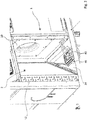
- FIG. 1 shows schematically and by way of example a side view of an air-water heat pump 1 according to the invention.
- the air-water heat pump 1 is not shown in its entirety, but in part, in particular in FIG Fig. 1 only the side view of a lower cold room 3 is shown, with an evaporator room 2 arranged above it in the perspective view shown in FIG Fig. 2 shown is visible.
- Fig. 2 As mentioned above, a perspective view of the air-to-water heat pump 1 is shown, with the evaporator chamber 2 being shown in particular.
- a fan 10 which is set up to guide air over an evaporator 12, is arranged in the evaporator space.
- the fan 10 is preferably designed to conduct air to the outside via a duct (not shown) from the installation room, which can be, for example, a boiler room, a utility room or a cellar room.
- the evaporator 12 is part of the refrigerant circuit, with the essential remaining components of the refrigerant circuit being arranged in the cold room 3 (cf. Fig. 1 ).
- the air-water heat pump 1 is divided into the two rooms, the evaporator room 2 and the cold room 3, with essentially a defrosting trough 14, which is designed to hold condensate when the evaporator 12 is defrosted, separating the two rooms Are defined.
- Operation of the fan 10 reliably transports refrigerant, for example flammable, combustible and / or unhealthy refrigerant such as R454C, which escapes in the event of a fault, from the sealed device to a non-critical area, for example outside the building.
- the refrigerant circuit is indicated schematically with the reference number 20 and comprises, for example, a compressor and a condenser 22.
- connections 32 are provided on the outside of the air-water heat pump, which connect the air-water heat pump 1 to a Enable power supply and / or heating circuits or domestic water circuits.
- the condensate or defrost pan 14 is also clearly visible.
- a condensate connection 40 with a siphon connects to the defrosting trough 14 and conducts condensate out of the housing to the outside.
- a safety valve 42 is arranged, which is triggered when the pressure in the hydraulic circuit increases.
- fluid is conducted from the hydraulic circuit via a hydraulic line 44 into the evaporator chamber 2.
- the safety valve 42 is thus emptied into the evaporator space 2 via an outlet 46, which enables the refrigerant and water to be separated by gravity.
- the water is collected in the defrosting pan 14 and discharged via the condensate connection 40. Gaseous refrigerant is separated from this by gravity and conveyed out of the sealed housing and out of the installation room via the fan 10.
- the suction concept covers every part of the refrigerant circuit 20, so that any refrigerant that may escape can be reliably guided to the outside from any position.
- any refrigerant that may escape into the hydraulic circuit can also be safely conveyed out of the installation room.
- the safety valve 42 is known in heat pumps; the modification which is particularly advantageous according to the invention relates to the hydraulic connection to this safety valve.
Landscapes
- Engineering & Computer Science (AREA)
- Physics & Mathematics (AREA)
- Mechanical Engineering (AREA)
- Thermal Sciences (AREA)
- General Engineering & Computer Science (AREA)
- Heat-Pump Type And Storage Water Heaters (AREA)
- Other Air-Conditioning Systems (AREA)
Abstract
Description
- Die vorliegende Erfindung betrifft eine Luft-Wasser-Wärmepumpe sowie ein Verfahren zum Betreiben einer Luft-Wasser-Wärmepumpe.
- Bei Luft-Wasser-Wärmepumpen, insbesondere bei innen aufgestellten Luft-Wasser-Wärmepumpen, ergeben sich durch die vermehrte Verwendung von leicht entzündlichen, brennbaren und/oder gesundheitsbeeinträchtigenden Kältemitteln neue Anforderungen an die Sicherheit der Anlagen. Insbesondere muss vermieden werden, dass derartige Kältemittel in den Aufstellraum der Luft-Wasser-Wärmepumpe austreten. Der Aufstellraum kann beispielsweise ein Heizungsraum, aber auch ein Hauswirtschaftsraum oder ein Kellerraum sein.
- Kommt es zu einem Fehlerfall, das heißt, dass Kältemittel aus dem Kältemittelkreis der Luft-Wasser-Wärmepumpe austritt, muss dieses in einen unkritischen Bereich, beispielsweise außerhalb des Gebäudes oder des Aufstellraums, transportiert werden. Alternativ muss der Aufstellraum ein bestimmtes Mindestvolumen überschreiten, was üblicherweise in der Praxis an den wesentlich zu kleinen Aufstellräumen scheitert.
- Ein Ausströmen von Kältemittel kann beispielsweise dadurch geschehen, dass der Verflüssiger des Kältekreises auffriert und Kältemittel dadurch in den hydraulischen Kreis gelangt. Ein Druckanstieg lässt daraufhin das Sicherheitsventil ansprechen, so dass das Wasser und im Fehlerfall auch das darin enthaltene Kältemittel in einen Siphon im Aufstellraum geleitet wird und in die Umgebung geraten kann.
- Vor diesem Hintergrund war es eine Aufgabe der vorliegenden Erfindung, eine Luft-Wasser-Wärmepumpe anzugeben, die bei leicht entzündlichen, brennbaren und/oder gesundheitsbeeinträchtigenden Kältemitteln einen sicheren Betrieb ermöglicht.
- Die Aufgabe wird erfindungsgemäß durch die nebengeordneten Ansprüche gelöst. Bevorzugte Ausgestaltungen werden in den Unteransprüchen angegeben.
- In einer Ausführung wird eine Luft-Wasser-Wärmepumpe vorgeschlagen, die aufweist a) einen Kältemittelkreis, b) einen Hydraulikkreis, c) einen nach außen abgedichteten Raum, genannt Verdampferraum, d) einen Verdampfer, e) einen Lüfter, der dazu eingerichtet ist, Luft über den Verdampfer zu führen, f) einen Verflüssiger, g) ein Sicherheitsventil, das in dem Hydraulikkreis dem Verflüssiger nachgelagert angeordnet ist. Der Verdampfer und der Lüfter sind in dem Verdampferraum angeordnet. Die Luft-Wasser-Wärmepumpe weist eine hydraulische Verbindung zwischen Sicherheitsventil und Verdampferraum auf.
- Somit wird das Wasser, beziehungsweise im Fehlerfall zusätzlich dazu Kältemittel, bei einem Ansprechen des Sicherheitsventils nicht aus der Luft-Wasser-Wärmepumpe in den Aufstellraum, sondern in den nach außen abgedichteten Verdampferraum geleitet. Aus diesem kann das Kältemittel mittels des Lüfters aus dem Aufstellraum heraus gefördert werden. Das Kältemittel, das aus der hydraulischen Verbindung ausströmt, ist insbesondere gasförmig. Im Falle einer entsprechenden vertikalen Anordnung ist eine Schwerkraftabscheidung von Wasser und Kältemittel möglich. Das Wasser kann beispielsweise über einen Kondensatanschluss mit Siphon gefahrlos nach außen geleitet werden.
- Anders ausgedrückt, anstatt einer Ausleitung nach außen gibt das Sicherheitsventil erfindungsgemäß Wasser und gegebenenfalls Kältemittel in einen geräteinternen Raum, den Verdampferraum, ab, in dem das Kältemittel vom Wasser abgeschieden werden kann und einzeln über verschiedene Öffnungen nach außen leitbar ist.
- Vorzugsweise weist die Luft-Wasser-Wärmepumpe weiter eine Abtauwanne auf, wobei die Abtauwanne unterhalb des Verdampfers im Verdampferraum angeordnet ist, wobei die hydraulische Verbindung einen Austritt von Flüssigkeit in die Abtauwanne ermöglicht.
- Die Abtauwanne ist sowieso vorgesehen, um an dem Verdampfer abfallendes Kondensat aufzunehmen und nach außen zu leiten. Somit erfährt diese Abtauwanne gemäß dieser bevorzugten Ausführung eine Funktionsintegration, da sie ferner in das Sicherheitssystem des Hydraulikkreises integriert ist und ein unerwünschtes Ausleiten von Kältemittel in den Aufstellraum unterbindet.
- Vorzugsweise weist die Abtauwanne einen Kondensatanschluss zum Ausleiten von Flüssigkeit nach außen auf.
- Vorzugsweise wirkt die Abtauwanne als Dichtelement zwischen Verdampferraum und dem Verflüssiger, wobei die Abtauwanne insbesondere über ein Verbindungselement, besonders bevorzugt eine Schraube, reversibel montierbar und demontierbar ist. Ist das für diese Erfindungsmeldung relevant oder kann das raus?
- Die Abtauwanne erfährt demnach eine weitere Funktionsintegration, nämlich die Abdichtung des Verdamperraumes von dem Kälteraum, in dem ein Großteil des Kälteaggregates einschließlich des Verflüssigers angeordnet ist. Die Möglichkeit der reversiblen Montage ermöglicht, dass zu Wartungszwecken einfach auf die darunterliegenden Komponenten und Bauteile zugegriffen werden kann, was die Wartbarkeit verbessert und Wartungen vereinfacht. - betrifft andere Erfindungsmeldung "herausnehmbare und luftdichte Abtauwanne"
- Vorzugsweise stellt die hydraulische Verbindung eine Schwerkraftabscheidung von Kältemittel und Wasser bereit. Hierzu weist die hydraulische Verbindung vorzugsweise eine entsprechende vertikale Anordnung auf.
- Vorzugsweise weist die Luft-Wasser-Wärmepumpe eine Steuerung auf. Die Steuerung ist dazu ausgebildet ist, den Lüfter permanent zu betreiben.
- So wird demnach der Lüfter, der in einer Luft-Wasser-Wärmepumpe bekanntermaßen vorhanden ist, um Luft über den Verdampfer zu führen, eingesetzt, um gleichzeitig eine permanente Ausleitung eventuell austretenden Kältemittels, insbesondere aus der hydraulischen Verbindung austretenden Kältemittels, zu gewährleisten. Hierzu wird die Steuerung, die bislang beispielsweise in einem Fall, in dem die Luft-Wasser-Wärmepumpe nicht betrieben wird, den Lüfter ausgeschaltet hat, derart modifiziert, dass der Lüfter permanent betrieben wird. Die erfindungsgemäße Luft-Wasser-Wärmepumpe erfordert demnach keine zusätzlichen Bauteile, wie beispielsweise zusätzliche Lüfter, Sensoren oder Überwachungsinstrumente und ermöglicht ein Sicherheitskonzept, das vermeidet, dass entzündliches, brennbares und/oder gesundheitsbeeinträchtigendes Kältemittel in einen Aufstellraum der Luft-Wasser-Wärmepumpe austritt.
- In einer Ausführung ist die Steuerung dazu ausgebildet, den Lüfter auch dann zu betreiben, wenn die Luft-Wasser-Wärmepumpe keine Umgebungsenergie aufnimmt, insbesondere auch dann, wenn ein Kompressor der Luft-Wasser-Wärmepumpe nicht betrieben wird und/oder sich die Luft-Wasser-Wärmepumpe in einem ausgeschalteten Betriebszustand befindet.
- In einer Ausführung weist die Luft-Wasser-Wärmepumpe ferner eine Sicherheitseinheit auf, wobei die Sicherheitseinheit dazu ausgebildet ist, eine Drehzahl des Lüfters zu überwachen.
- Herkömmlich ist bekannt, das Ausströmen von Kältemittel mittels Druckdosen zu überwachen. Indem die erfindungsgemäße Sicherheitseinheit die Drehzahl des Lüfters überwacht, kann auf das zusätzliche Vorsehen der Druckdose verzichtet werden. Dadurch wird die Luft-Wasser-Wärmepumpe strukturell vereinfacht und in der Komplexität reduziert. Solange der Lüfter läuft, das heißt, solange die Sicherheitseinheit eine Drehzahl des Lüfters feststellt, ist die Sicherheit der Luft-Wasser-Wärmepumpe gewährleistet, da mit dem laufenden Lüfter ein Abtransport von eventuell austretendem Kältemittel sichergestellt ist. Die Sicherheitseinheit kann beispielsweise im Fehlerfall, das heißt, wenn die Drehzahl des Lüfters gleich null ist oder anderweitig von der erwarteten Größe abweicht, ein Signal an eine weitere Einheit ausgeben, sodass die Wartung der Luft-Wasser-Wärmepumpe vorgenommen werden kann. Für die Übertragung dieses Signals sind keine Grenzen gesetzt. Das Signal kann beispielsweise drahtgebunden oder drahtlos an ein Bedienelement der Luft-Wasser-Wärmepumpe selbst oder auch direkt und/oder über einen Server an ein mobiles Endgerät wie ein Smartphone übersandt werden.
- In einer Ausführung weist die Luft-Wasser-Wärmepumpe neben dem Verdampferraum einen Kälteraum auf, wobei der Verdampfer und der Lüfter in dem Verdampferraum und ein Kompressor und ein Verflüssiger in dem Kälteraum angeordnet ist, wobei eine Verbindung zwischen Kälteraum und Verdampferraum besteht, derart, dass durch den Betrieb des Lüfters ein permanenter Unterdruck in dem Kälteraum aufrechterhalten wird. Überschneidung mit "Erfindungsmeldung Absaugkonzept WPL ICS"
- Durch den permanenten Unterdruck in dem Kälteraum ist sichergestellt, dass die Ausleitung eventuell austretenden Kältemittels, d.h. auch an sonstigen Stellen des Kältekreises austretendes Kältemittel, durch den Lüfter und nicht durch andere Öffnungen des Kälteraumes zu dem Aufstellraum gewährleistet ist. Der Kälteraum muss entsprechend abgedichtet sein, damit es zu dem Unterdruck kommen kann. Vorzugsweise ist die Verbindung zwischen Kälteraum und Verdampferraum die einzige Öffnung des Kälteraumes nach außen.
- In einer Ausführung ist die Steuerung dazu ausgebildet, eine Drehzahl des Lüfters abzusenken, wenn sich die Luft-Wasser-Wärmepumpe in einem ausgeschalteten Betriebszustand befindet.
- Indem die Drehzahl des Lüfters in dem ausgeschalteten Betriebszustand der Luft-Wasser-Wärmepumpe abgesenkt wird, reduziert sich die Bereitschaftsleistungsaufnahme der Luft-Wasser-Wärmepumpe auf einen niedrigen Wert. Beispielsweise kann eine Leistungsaufnahme im Bereitschaftsfall, das heißt, in einem Fall, in dem die Wärmepumpe ausgeschaltet ist, auf unter 4 Watt gehalten werden, wobei dies den Betrieb des Lüfters und vorzugsweise auch die Leistungsaufnahme von Leistungselektronik, wie Invertern, einschließt.
- In einer Ausführung umfasst der Kältemittelkreis ein entzündliches, brennbares und/oder gesundheitsbeeinträchtigendes Kältemittel. Bei der Verwendung derartiger Kältemittel ist das erfindungsgemäß erarbeitete Sicherheitskonzept besonders vorteilhaft. Es wird eine sichere Ausleitung des Kältemittels auch dann gewährleistet, wenn dieses aus dem Kältemittelkreis austritt. Vorzugsweise umfasst das Kältemittel R454C, wobei auch die Verwendung anderer Kältemittel möglich ist.
- In einer Ausführung ist die Luft-Wasser-Wärmepumpe als innenaufgestellte Luft-Wasser-Wärmepumpe ausgebildet.
- In einer Ausführung weist die Luft-Wasser-Wärmepumpe ferner einen an den Lüfter angrenzenden Luftkanal zum Ausleiten von Luft aus dem Aufstellraum auf, wobei insbesondere aus dem Kältemittelkreis austretendes Kältemittel durch den permanenten Betrieb des Lüfters aus dem Aufstellraum ausgeleitet wird.
- Weitere Vorteile und bevorzugte Ausgestaltungen werden nachfolgend mit Verweis auf die beigefügten Figuren beschrieben. Hierbei zeigen:
- Fig. 1
- schematisch und exemplarisch eine Seitenansicht einer Luft-Wasser-Wärmepumpe und
- Fig. 2
- schematisch und exemplarisch eine perspektivische Ansicht der Luft-Wasser-Wärmepumpe aus
Fig. 1 . -
Fig. 1 zeigt schematisch und exemplarisch eine Seitenansicht einer erfindungsgemäßen Luft-Wasser-Wärmepumpe 1. Die Luft-Wasser-Wärmepumpe 1 ist nicht vollständig, sondern auszugsweise gezeigt, insbesondere ist inFig. 1 nur die Seitenansicht eines unteren Kälteraumes 3 gezeigt, wobei ein darüber angeordneter Verdampferraum 2 in der perspektivischen Ansicht, die inFig. 2 gezeigt ist, sichtbar ist. - In
Fig. 2 ist, wie oben erwähnt, eine perspektivische Ansicht der Luft-Wasser-Wärmepumpe 1 gezeigt, wobei insbesondere der Verdampferraum 2 zu sehen ist. In dem Verdampferraum ist ein Lüfter 10, der dazu eingerichtet ist, Luft über einen Verdampfer 12 zu führen angeordnet. Unterhalb des Verdampferraumes 2 befindet sich ein Kälteraum 3, der nachfolgend mit Verweis aufFig. 2 detailliert beschrieben wird. - Der Lüfter 10 ist vorzugsweise dazu ausgebildet, Luft über einen nicht gezeigten Kanal aus dem Aufstellraum, der beispielsweise ein Heizungsraum, ein Hauswirtschaftsraum oder ein Kellerraum sein kann, nach außen zu leiten.
- Der Verdampfer 12 ist Teil des Kältemittelkreises, wobei die wesentlichen verbleibenden Komponenten des Kältemittelkreises in dem Kälteraum 3 angeordnet sind (vgl.
Fig. 1 ). - Wie erwähnt ist die Luft-Wasser-Wärmepumpe 1 in die zwei Räume, den Verdampferraum 2 und den Kälteraum 3, aufgeteilt, wobei im Wesentlichen eine Abtauwanne 14, die zur Aufnahme von Kondensat beim Abtauen des Verdampfers 12 ausgebildet ist, die Trennung der beiden Räume definiert. Ein Betrieb des Lüfters 10 transportiert Kältemittel, beispielsweise entzündliches, brennbares und/oder gesundheitsbeeinträchtigendes Kältemittel wie R454C, das im Fehlerfall austritt, zuverlässig aus dem abgedichteten Gerät in einen unkritischen Bereich beispielsweise außerhalb des Gebäudes.
- Zurück zu
Fig. 1 , in der der Kälteraum 3 ohne eine vordere Abdeckung gezeigt ist, sodass die inneren Komponenten sichtbar sind. Der Kältemittelkreis ist schematisch mit dem Bezugszeichen 20 gekennzeichnet und umfasst beispielsweise einen Kompressor und einen Verflüssiger 22. Im Bereich des Kälteraumes 3 sind an der Außenseite der Luft-Wasser-Wärmepumpe Anschlüsse 32 vorgesehen, die einen Anschluss der Luft-Wasser-Wärmepumpe 1 an eine Stromversorgung und/oder Heizkreise bzw. Brauchwasserkreise ermöglichen. Auch die Kondensat- bzw. Abtauwanne 14 ist gut erkennbar. An die Abtauwanne 14 schließt sich ein Kondensatanschluss 40 mit Siphon an, der Kondensat aus dem Gehäuse nach außen leitet. - Im Vorlauf des Hydraulikkreises der Luft-Wasser-Wärmepumpe 1 nach dem Verflüssiger 22 ist ein Sicherheitsventil 42 angeordnet, das auslöst, wenn der Druck in dem Hydraulickreis ansteigt. Bei Auslösung wird Fluid aus dem Hydraulikkreis über eine hydraulische Leitung 44 in den Verdampferraum 2 geleitet. Über einen Austritt 46, der eine Schwerkraftabscheidung von Kältemittel und Wasser ermöglicht, entleert sich das Sicherheitsventil 42 also in den Verdampferraum 2. Das Wasser wird in der Abtauwanne 14 gesammelt und über den Kondensatanschluss 40 ausgeleitet. Gasförmiges Kältemittel wird hiervon durch die Schwerkraft abgeschieden und über den Lüfter 10 aus dem abgedichteten Gehäuse und aus dem Aufstellraum gefördert.
- Somit wird ein durch eine in den
Fig. 1 und2 nicht gezeigte Steuerung der Luft-Wasser-Wärmepumpe 1 permanent betriebener Lüfter 10 zur Abfuhr von Kältemittel an die Außenluft vorgeschlagen. Das Absaugkonzept deckt jeden Teil des Kältemittelkreises 20 ab, sodass gegebenenfalls austretendes Kältemittel von jeder Position zuverlässig nach außen geführt werden kann. Insbesondere kann durch die beispielhaft gezeigte Ausgestaltung des Sicherheitsventils 42 auch eventuell in den Hydraulikkreis austretendes Kältemittel sicher aus dem Aufstellraum befördert werden. Das Sicherheitsventil 42 ist bei Wärmepumpen bekannt, die erfindungsgemäß besonders vorteilhafte Modifikation betrifft den hydraulischen Anschluss an dieses Sicherheitsventil. - Es ist besonders vorteilhaft, den Lüfter 10 dann, wenn die Wärmepumpe keine Wärme erzeugt, mit geringerer Drehzahl zu betreiben, um die Bereitschaftsverluste zu minimieren. Da die Drehzahl des Lüfters 10 überwacht wird, ist keine extra Druckdose zum Erkennen von austretendem Kältemittel nötig. Schließlich wird dadurch, dass der Lüfter 10, der sowieso Teil einer Luft-Wasser-Wärmepumpe 1 ist, durch eine weitere Funktion ergänzt wird, die Funktionsintegration erhöht und die Komplexität der Luft-Wasser-Wärmepumpe 1 als Ganzes verringert.
Claims (10)
- Luft-Wasser-Wärmepumpe (1), die aufweist- einen Kältemittelkreis (20),- einen Hydraulikkreis,- einen nach außen abgedichteten Raum, genannt Verdampferraum (2),- einen Verdampfer (12),- einen Lüfter (10), der dazu eingerichtet ist, Luft über den Verdampfer (12) zu führen,- einen Verflüssiger (22),- ein Sicherheitsventil (42), das in dem Hydraulikkreis dem Verflüssiger (22) nachgelagert angeordnet ist,wobei der Verdampfer (12) und der Lüfter (10) in dem Verdampferraum (2) angeordnet sind,dadurch gekennzeichnet, dass die Luft-Wasser-Wärmepumpe (1) eine hydraulische Verbindung (44) zwischen Sicherheitsventil (42) und Verdampferraum (2) aufweist.
- Luft-Wasser-Wärmepumpe (1) nach Anspruch 1, die weiter eine Abtauwanne (14) aufweist, wobei die Abtauwanne (14) unterhalb des Verdampfers (12) im Verdampferraum (2) angeordnet ist, wobei die hydraulische Verbindung (44) einen Austritt (46) von Flüssigkeit in die Abtauwanne ermöglicht.
- Luft-Wasser-Wärmepumpe (1) nach Anspruch 2, wobei die Abtauwanne (14) einen Kondensatanschluss (40) zum Ausleiten von Flüssigkeit nach außen aufweist.
- Luft-Wasser-Wärmepumpe (1) nach Anspruch 2 oder 3, wobei die Abtauwanne (14) als Dichtelement zwischen Verdampferraum (2) und dem Verflüssiger (22) wirkt, wobei die Abtauwanne (14) insbesondere über ein Verbindungselement, besonders bevorzugt eine Schraube, reversibel montierbar und demontierbar ist.
- Luft-Wasser-Wärmepumpe (1) nach einem der vorstehenden Ansprüche, wobei die hydraulische Verbindung (44) eine Schwerkraftabscheidung von Kältemittel und Wasser bereitstellt.
- Luft-Wasser-Wärmepumpe (1) nach einem der vorstehenden Ansprüche, die weiter eine Steuerung aufweist, wobei die Steuerung dazu ausgebildet ist, den Lüfter (10) auch dann zu betreiben, wenn die Luft-Wasser-Wärmepumpe (1) keine Umgebungsenergie aufnimmt, insbesondere auch dann, wenn ein Kompressor der Luft-Wasser-Wärmepumpe (1) nicht betrieben wird und/oder sich die Luft-Wasser-Wärmepumpe (1) in einem ausgeschalteten Betriebszustand befindet.
- Luft-Wasser-Wärmepumpe (1) nach einem der vorstehenden Ansprüche, die ferner eine Sicherheitseinheit aufweist, wobei die Sicherheitseinheit dazu ausgebildet ist, eine Drehzahl des Lüfters (10) zu überwachen.
- Luft-Wasser-Wärmepumpe (1) nach einem der vorstehenden Ansprüche, wobei die Steuerung dazu ausgebildet ist, eine Drehzahl des Lüfters (10) abzusenken, wenn sich die Luft-Wasser-Wärmepumpe (1) in einem ausgeschalteten Betriebszustand befindet.
- Luft-Wasser-Wärmepumpe (1) nach einem der vorstehenden Ansprüche, wobei der Kältemittelkreis (20) ein entzündliches, brennbares und/oder gesundheitsbeeinträchtigendes Kältemittel, insbesondere R454c, umfasst.
- Luft-Wasser-Wärmepumpe (1) nach einem der vorstehenden Ansprüche, wobei die Luft-Wasser-Wärmepumpe (1) als innenaufgestellte Luft-Wasser-Wärmepumpe (1) ausgebildet ist, wobei die Luft-Wasser-Wärmepumpe (1) ferner einen an den Lüfter (10) angrenzenden Luftkanal zum Ausleiten von Luft aus dem Aufstellraum aufweist, wobei insbesondere aus dem Kältemittelkreis (20) austretendes Kältemittel durch den permanenten Betrieb des Lüfters (10) aus dem Aufstellraum ausgeleitet wird.
Applications Claiming Priority (1)
| Application Number | Priority Date | Filing Date | Title |
|---|---|---|---|
| DE102019001630 | 2019-03-08 |
Publications (2)
| Publication Number | Publication Date |
|---|---|
| EP3705812A1 true EP3705812A1 (de) | 2020-09-09 |
| EP3705812B1 EP3705812B1 (de) | 2023-08-09 |
Family
ID=70227967
Family Applications (1)
| Application Number | Title | Priority Date | Filing Date |
|---|---|---|---|
| EP20401016.9A Active EP3705812B1 (de) | 2019-03-08 | 2020-03-06 | Luft-wasser-wärmepumpe |
Country Status (3)
| Country | Link |
|---|---|
| EP (1) | EP3705812B1 (de) |
| DE (1) | DE102020100806A1 (de) |
| PL (1) | PL3705812T3 (de) |
Families Citing this family (4)
| Publication number | Priority date | Publication date | Assignee | Title |
|---|---|---|---|---|
| DE102022130478A1 (de) * | 2022-11-17 | 2024-05-23 | Vaillant Gmbh | Feuchtemanagement in einem Wärmepumpengehäuse |
| EP4336119B1 (de) | 2022-09-09 | 2026-03-25 | Vaillant GmbH | Feuchtemanagement und kondensatableitung für ein wärmepumpengehäuse |
| DE102023136094A1 (de) * | 2023-12-20 | 2025-06-26 | Stiebel Eltron Gmbh & Co. Kg | Luft-Wasser-Wärmepumpe und zugehöriges Verfahren |
| DE102024105599A1 (de) | 2024-02-28 | 2025-08-28 | Vaillant Gmbh | Siphon mit Sicherheitssperrvorrichtung |
Citations (5)
| Publication number | Priority date | Publication date | Assignee | Title |
|---|---|---|---|---|
| DE7710968U1 (de) * | 1977-04-06 | 1977-07-21 | Siemens Ag, 1000 Berlin Und 8000 Muenchen | Anschlussfertiges heizgeraet |
| DE3303125A1 (de) * | 1983-01-31 | 1984-08-02 | Stiebel Eltron Gmbh & Co Kg, 3450 Holzminden | Luft/wasser-waermepumpe |
| JP2002098346A (ja) * | 2000-09-26 | 2002-04-05 | Daikin Ind Ltd | 空気調和機の室内機 |
| DE102009057481A1 (de) * | 2009-12-10 | 2011-06-16 | Stiebel Eltron Gmbh & Co. Kg | Außenluft-führendes Haustechnikgerät |
| EP3336453A1 (de) * | 2016-10-17 | 2018-06-20 | Mitsubishi Electric Corporation | Innenraumeinheit einer wärmepumpennutzungsvorrichtung und wärmepumpennutzungsvorrichtung damit |
Family Cites Families (1)
| Publication number | Priority date | Publication date | Assignee | Title |
|---|---|---|---|---|
| DE9304301U1 (de) * | 1993-03-23 | 1993-06-03 | Schütz, Peter, 4152 Kempen | Kälteanlage |
-
2020
- 2020-01-15 DE DE102020100806.6A patent/DE102020100806A1/de active Pending
- 2020-03-06 PL PL20401016.9T patent/PL3705812T3/pl unknown
- 2020-03-06 EP EP20401016.9A patent/EP3705812B1/de active Active
Patent Citations (5)
| Publication number | Priority date | Publication date | Assignee | Title |
|---|---|---|---|---|
| DE7710968U1 (de) * | 1977-04-06 | 1977-07-21 | Siemens Ag, 1000 Berlin Und 8000 Muenchen | Anschlussfertiges heizgeraet |
| DE3303125A1 (de) * | 1983-01-31 | 1984-08-02 | Stiebel Eltron Gmbh & Co Kg, 3450 Holzminden | Luft/wasser-waermepumpe |
| JP2002098346A (ja) * | 2000-09-26 | 2002-04-05 | Daikin Ind Ltd | 空気調和機の室内機 |
| DE102009057481A1 (de) * | 2009-12-10 | 2011-06-16 | Stiebel Eltron Gmbh & Co. Kg | Außenluft-führendes Haustechnikgerät |
| EP3336453A1 (de) * | 2016-10-17 | 2018-06-20 | Mitsubishi Electric Corporation | Innenraumeinheit einer wärmepumpennutzungsvorrichtung und wärmepumpennutzungsvorrichtung damit |
Also Published As
| Publication number | Publication date |
|---|---|
| DE102020100806A1 (de) | 2020-09-10 |
| PL3705812T3 (pl) | 2024-01-29 |
| EP3705812B1 (de) | 2023-08-09 |
Similar Documents
| Publication | Publication Date | Title |
|---|---|---|
| EP4596994B1 (de) | Kältemittelanlage sowie kältemittelmodul | |
| EP3705812B1 (de) | Luft-wasser-wärmepumpe | |
| DE102019001637A1 (de) | Luft-Wasser-Wärmepumpe und zugehöriges Verfahren | |
| DE112018006844B4 (de) | Klimaanlage | |
| DE102008054081B4 (de) | Verfahren zum Klimatisieren eines Schaltschrankes | |
| DE69000952T2 (de) | Transportkuehlsystem mit mitteln zum vergroessern der kapazitaet eines heizzyklus. | |
| DE102021201712A1 (de) | Wärmepumpenanlage sowie Verfahren zum Betreiben einer Wärmepumpenanlage | |
| EP2256438B1 (de) | Verbesserte Kälteerzeugungsvorrichtung, insbesondere für Flugzeuge | |
| EP4050284B1 (de) | Wärmepumpe | |
| EP3705799B1 (de) | Wärmepumpe | |
| DE112015000790B4 (de) | Klimatisierungsvorrichtung | |
| EP3767186B1 (de) | Verfahren zur steuerung einer ausseneinheit einer wärmepumpe | |
| EP2681979B1 (de) | Kühleinrichtung, insbesondere klimatisierungseinrichtung für eine computeranlage | |
| CH708202A2 (de) | Lüftungsanlage. | |
| CH705961A2 (de) | Raumlüftungssystem. | |
| DE102006013587A1 (de) | Wärmepumpe | |
| EP3540323A2 (de) | Dezentralisierte luftbehandlungsvorrichtung | |
| DE102013109702A1 (de) | Luftauslass sowie Verfahren zu dessen Umrüstung | |
| EP4336108B1 (de) | Kältemittelabscheidung im heizungskreislauf | |
| AT513855B1 (de) | Verfahren zum Steuern einer Klimaanlage | |
| DE102024129493A1 (de) | Gaserfassungseinheit zur leckminderung | |
| DE102017104538A1 (de) | Anordnung eines Kühlsystems zur Kühlung mindestens eines, in einem Raum angeordneten Serverschranks | |
| EP4575336A1 (de) | Luft-wasser-wärmepumpe und zugehöriges verfahren | |
| EP3767187B1 (de) | Verfahren zur steuerung einer wärmepumpenanordnung | |
| AT509723B1 (de) | Frostschutzeinrichtung |
Legal Events
| Date | Code | Title | Description |
|---|---|---|---|
| PUAI | Public reference made under article 153(3) epc to a published international application that has entered the european phase |
Free format text: ORIGINAL CODE: 0009012 |
|
| STAA | Information on the status of an ep patent application or granted ep patent |
Free format text: STATUS: THE APPLICATION HAS BEEN PUBLISHED |
|
| AK | Designated contracting states |
Kind code of ref document: A1 Designated state(s): AL AT BE BG CH CY CZ DE DK EE ES FI FR GB GR HR HU IE IS IT LI LT LU LV MC MK MT NL NO PL PT RO RS SE SI SK SM TR |
|
| AX | Request for extension of the european patent |
Extension state: BA ME |
|
| STAA | Information on the status of an ep patent application or granted ep patent |
Free format text: STATUS: REQUEST FOR EXAMINATION WAS MADE |
|
| 17P | Request for examination filed |
Effective date: 20210309 |
|
| RBV | Designated contracting states (corrected) |
Designated state(s): AL AT BE BG CH CY CZ DE DK EE ES FI FR GB GR HR HU IE IS IT LI LT LU LV MC MK MT NL NO PL PT RO RS SE SI SK SM TR |
|
| REG | Reference to a national code |
Ref country code: DE Ref legal event code: R079 Free format text: PREVIOUS MAIN CLASS: F25B0030020000 Ipc: F25B0049020000 Ref country code: DE Ref legal event code: R079 Ref document number: 502020004611 Country of ref document: DE Free format text: PREVIOUS MAIN CLASS: F25B0030020000 Ipc: F25B0049020000 |
|
| GRAP | Despatch of communication of intention to grant a patent |
Free format text: ORIGINAL CODE: EPIDOSNIGR1 |
|
| RIC1 | Information provided on ipc code assigned before grant |
Ipc: F25B 41/40 20210101ALI20230209BHEP Ipc: F25B 41/00 20060101ALI20230209BHEP Ipc: F25B 30/02 20060101ALI20230209BHEP Ipc: F25B 49/02 20060101AFI20230209BHEP |
|
| STAA | Information on the status of an ep patent application or granted ep patent |
Free format text: STATUS: GRANT OF PATENT IS INTENDED |
|
| INTG | Intention to grant announced |
Effective date: 20230316 |
|
| P01 | Opt-out of the competence of the unified patent court (upc) registered |
Effective date: 20230524 |
|
| GRAS | Grant fee paid |
Free format text: ORIGINAL CODE: EPIDOSNIGR3 |
|
| GRAA | (expected) grant |
Free format text: ORIGINAL CODE: 0009210 |
|
| STAA | Information on the status of an ep patent application or granted ep patent |
Free format text: STATUS: THE PATENT HAS BEEN GRANTED |
|
| AK | Designated contracting states |
Kind code of ref document: B1 Designated state(s): AL AT BE BG CH CY CZ DE DK EE ES FI FR GB GR HR HU IE IS IT LI LT LU LV MC MK MT NL NO PL PT RO RS SE SI SK SM TR |
|
| REG | Reference to a national code |
Ref country code: GB Ref legal event code: FG4D Free format text: NOT ENGLISH |
|
| REG | Reference to a national code |
Ref country code: CH Ref legal event code: EP |
|
| REG | Reference to a national code |
Ref country code: DE Ref legal event code: R096 Ref document number: 502020004611 Country of ref document: DE |
|
| REG | Reference to a national code |
Ref country code: IE Ref legal event code: FG4D Free format text: LANGUAGE OF EP DOCUMENT: GERMAN |
|
| REG | Reference to a national code |
Ref country code: NL Ref legal event code: FP |
|
| REG | Reference to a national code |
Ref country code: LT Ref legal event code: MG9D |
|
| REG | Reference to a national code |
Ref country code: SE Ref legal event code: TRGR |
|
| PG25 | Lapsed in a contracting state [announced via postgrant information from national office to epo] |
Ref country code: GR Free format text: LAPSE BECAUSE OF FAILURE TO SUBMIT A TRANSLATION OF THE DESCRIPTION OR TO PAY THE FEE WITHIN THE PRESCRIBED TIME-LIMIT Effective date: 20231110 |
|
| PG25 | Lapsed in a contracting state [announced via postgrant information from national office to epo] |
Ref country code: IS Free format text: LAPSE BECAUSE OF FAILURE TO SUBMIT A TRANSLATION OF THE DESCRIPTION OR TO PAY THE FEE WITHIN THE PRESCRIBED TIME-LIMIT Effective date: 20231209 |
|
| PG25 | Lapsed in a contracting state [announced via postgrant information from national office to epo] |
Ref country code: RS Free format text: LAPSE BECAUSE OF FAILURE TO SUBMIT A TRANSLATION OF THE DESCRIPTION OR TO PAY THE FEE WITHIN THE PRESCRIBED TIME-LIMIT Effective date: 20230809 Ref country code: PT Free format text: LAPSE BECAUSE OF FAILURE TO SUBMIT A TRANSLATION OF THE DESCRIPTION OR TO PAY THE FEE WITHIN THE PRESCRIBED TIME-LIMIT Effective date: 20231211 Ref country code: NO Free format text: LAPSE BECAUSE OF FAILURE TO SUBMIT A TRANSLATION OF THE DESCRIPTION OR TO PAY THE FEE WITHIN THE PRESCRIBED TIME-LIMIT Effective date: 20231109 Ref country code: LV Free format text: LAPSE BECAUSE OF FAILURE TO SUBMIT A TRANSLATION OF THE DESCRIPTION OR TO PAY THE FEE WITHIN THE PRESCRIBED TIME-LIMIT Effective date: 20230809 Ref country code: LT Free format text: LAPSE BECAUSE OF FAILURE TO SUBMIT A TRANSLATION OF THE DESCRIPTION OR TO PAY THE FEE WITHIN THE PRESCRIBED TIME-LIMIT Effective date: 20230809 Ref country code: IS Free format text: LAPSE BECAUSE OF FAILURE TO SUBMIT A TRANSLATION OF THE DESCRIPTION OR TO PAY THE FEE WITHIN THE PRESCRIBED TIME-LIMIT Effective date: 20231209 Ref country code: HR Free format text: LAPSE BECAUSE OF FAILURE TO SUBMIT A TRANSLATION OF THE DESCRIPTION OR TO PAY THE FEE WITHIN THE PRESCRIBED TIME-LIMIT Effective date: 20230809 Ref country code: GR Free format text: LAPSE BECAUSE OF FAILURE TO SUBMIT A TRANSLATION OF THE DESCRIPTION OR TO PAY THE FEE WITHIN THE PRESCRIBED TIME-LIMIT Effective date: 20231110 Ref country code: FI Free format text: LAPSE BECAUSE OF FAILURE TO SUBMIT A TRANSLATION OF THE DESCRIPTION OR TO PAY THE FEE WITHIN THE PRESCRIBED TIME-LIMIT Effective date: 20230809 |
|
| PG25 | Lapsed in a contracting state [announced via postgrant information from national office to epo] |
Ref country code: ES Free format text: LAPSE BECAUSE OF FAILURE TO SUBMIT A TRANSLATION OF THE DESCRIPTION OR TO PAY THE FEE WITHIN THE PRESCRIBED TIME-LIMIT Effective date: 20230809 |
|
| PG25 | Lapsed in a contracting state [announced via postgrant information from national office to epo] |
Ref country code: SM Free format text: LAPSE BECAUSE OF FAILURE TO SUBMIT A TRANSLATION OF THE DESCRIPTION OR TO PAY THE FEE WITHIN THE PRESCRIBED TIME-LIMIT Effective date: 20230809 Ref country code: RO Free format text: LAPSE BECAUSE OF FAILURE TO SUBMIT A TRANSLATION OF THE DESCRIPTION OR TO PAY THE FEE WITHIN THE PRESCRIBED TIME-LIMIT Effective date: 20230809 Ref country code: ES Free format text: LAPSE BECAUSE OF FAILURE TO SUBMIT A TRANSLATION OF THE DESCRIPTION OR TO PAY THE FEE WITHIN THE PRESCRIBED TIME-LIMIT Effective date: 20230809 Ref country code: EE Free format text: LAPSE BECAUSE OF FAILURE TO SUBMIT A TRANSLATION OF THE DESCRIPTION OR TO PAY THE FEE WITHIN THE PRESCRIBED TIME-LIMIT Effective date: 20230809 Ref country code: DK Free format text: LAPSE BECAUSE OF FAILURE TO SUBMIT A TRANSLATION OF THE DESCRIPTION OR TO PAY THE FEE WITHIN THE PRESCRIBED TIME-LIMIT Effective date: 20230809 Ref country code: SK Free format text: LAPSE BECAUSE OF FAILURE TO SUBMIT A TRANSLATION OF THE DESCRIPTION OR TO PAY THE FEE WITHIN THE PRESCRIBED TIME-LIMIT Effective date: 20230809 |
|
| REG | Reference to a national code |
Ref country code: DE Ref legal event code: R097 Ref document number: 502020004611 Country of ref document: DE |
|
| PG25 | Lapsed in a contracting state [announced via postgrant information from national office to epo] |
Ref country code: IT Free format text: LAPSE BECAUSE OF FAILURE TO SUBMIT A TRANSLATION OF THE DESCRIPTION OR TO PAY THE FEE WITHIN THE PRESCRIBED TIME-LIMIT Effective date: 20230809 |
|
| PLBE | No opposition filed within time limit |
Free format text: ORIGINAL CODE: 0009261 |
|
| STAA | Information on the status of an ep patent application or granted ep patent |
Free format text: STATUS: NO OPPOSITION FILED WITHIN TIME LIMIT |
|
| 26N | No opposition filed |
Effective date: 20240513 |
|
| PG25 | Lapsed in a contracting state [announced via postgrant information from national office to epo] |
Ref country code: SI Free format text: LAPSE BECAUSE OF FAILURE TO SUBMIT A TRANSLATION OF THE DESCRIPTION OR TO PAY THE FEE WITHIN THE PRESCRIBED TIME-LIMIT Effective date: 20230809 |
|
| PG25 | Lapsed in a contracting state [announced via postgrant information from national office to epo] |
Ref country code: BG Free format text: LAPSE BECAUSE OF FAILURE TO SUBMIT A TRANSLATION OF THE DESCRIPTION OR TO PAY THE FEE WITHIN THE PRESCRIBED TIME-LIMIT Effective date: 20230809 |
|
| PG25 | Lapsed in a contracting state [announced via postgrant information from national office to epo] |
Ref country code: LU Free format text: LAPSE BECAUSE OF NON-PAYMENT OF DUE FEES Effective date: 20240306 |
|
| PG25 | Lapsed in a contracting state [announced via postgrant information from national office to epo] |
Ref country code: MC Free format text: LAPSE BECAUSE OF FAILURE TO SUBMIT A TRANSLATION OF THE DESCRIPTION OR TO PAY THE FEE WITHIN THE PRESCRIBED TIME-LIMIT Effective date: 20230809 |
|
| PG25 | Lapsed in a contracting state [announced via postgrant information from national office to epo] |
Ref country code: MC Free format text: LAPSE BECAUSE OF FAILURE TO SUBMIT A TRANSLATION OF THE DESCRIPTION OR TO PAY THE FEE WITHIN THE PRESCRIBED TIME-LIMIT Effective date: 20230809 Ref country code: LU Free format text: LAPSE BECAUSE OF NON-PAYMENT OF DUE FEES Effective date: 20240306 Ref country code: BG Free format text: LAPSE BECAUSE OF FAILURE TO SUBMIT A TRANSLATION OF THE DESCRIPTION OR TO PAY THE FEE WITHIN THE PRESCRIBED TIME-LIMIT Effective date: 20230809 |
|
| REG | Reference to a national code |
Ref country code: BE Ref legal event code: MM Effective date: 20240331 |
|
| PG25 | Lapsed in a contracting state [announced via postgrant information from national office to epo] |
Ref country code: BE Free format text: LAPSE BECAUSE OF NON-PAYMENT OF DUE FEES Effective date: 20240331 |
|
| PG25 | Lapsed in a contracting state [announced via postgrant information from national office to epo] |
Ref country code: IE Free format text: LAPSE BECAUSE OF NON-PAYMENT OF DUE FEES Effective date: 20240306 |
|
| PG25 | Lapsed in a contracting state [announced via postgrant information from national office to epo] |
Ref country code: BE Free format text: LAPSE BECAUSE OF NON-PAYMENT OF DUE FEES Effective date: 20240331 Ref country code: IE Free format text: LAPSE BECAUSE OF NON-PAYMENT OF DUE FEES Effective date: 20240306 |
|
| PGFP | Annual fee paid to national office [announced via postgrant information from national office to epo] |
Ref country code: CH Payment date: 20250401 Year of fee payment: 6 |
|
| PG25 | Lapsed in a contracting state [announced via postgrant information from national office to epo] |
Ref country code: CY Free format text: LAPSE BECAUSE OF FAILURE TO SUBMIT A TRANSLATION OF THE DESCRIPTION OR TO PAY THE FEE WITHIN THE PRESCRIBED TIME-LIMIT; INVALID AB INITIO Effective date: 20200306 |
|
| PG25 | Lapsed in a contracting state [announced via postgrant information from national office to epo] |
Ref country code: HU Free format text: LAPSE BECAUSE OF FAILURE TO SUBMIT A TRANSLATION OF THE DESCRIPTION OR TO PAY THE FEE WITHIN THE PRESCRIBED TIME-LIMIT; INVALID AB INITIO Effective date: 20200306 |
|
| PG25 | Lapsed in a contracting state [announced via postgrant information from national office to epo] |
Ref country code: TR Free format text: LAPSE BECAUSE OF FAILURE TO SUBMIT A TRANSLATION OF THE DESCRIPTION OR TO PAY THE FEE WITHIN THE PRESCRIBED TIME-LIMIT Effective date: 20230809 |
|
| REG | Reference to a national code |
Ref country code: CH Ref legal event code: U11 Free format text: ST27 STATUS EVENT CODE: U-0-0-U10-U11 (AS PROVIDED BY THE NATIONAL OFFICE) Effective date: 20260401 |
|
| PGFP | Annual fee paid to national office [announced via postgrant information from national office to epo] |
Ref country code: SE Payment date: 20260319 Year of fee payment: 7 |
|
| PGFP | Annual fee paid to national office [announced via postgrant information from national office to epo] |
Ref country code: GB Payment date: 20260324 Year of fee payment: 7 |
|
| PGFP | Annual fee paid to national office [announced via postgrant information from national office to epo] |
Ref country code: DE Payment date: 20260319 Year of fee payment: 7 |
|
| PGFP | Annual fee paid to national office [announced via postgrant information from national office to epo] |
Ref country code: AT Payment date: 20260320 Year of fee payment: 7 |
|
| PGFP | Annual fee paid to national office [announced via postgrant information from national office to epo] |
Ref country code: NL Payment date: 20260319 Year of fee payment: 7 |
|
| PGFP | Annual fee paid to national office [announced via postgrant information from national office to epo] |
Ref country code: FR Payment date: 20260320 Year of fee payment: 7 |
|
| PGFP | Annual fee paid to national office [announced via postgrant information from national office to epo] |
Ref country code: CZ Payment date: 20260302 Year of fee payment: 7 |
|
| PGFP | Annual fee paid to national office [announced via postgrant information from national office to epo] |
Ref country code: PL Payment date: 20260227 Year of fee payment: 7 |