EP3705714A1 - Engine - Google Patents
Engine Download PDFInfo
- Publication number
- EP3705714A1 EP3705714A1 EP18872591.5A EP18872591A EP3705714A1 EP 3705714 A1 EP3705714 A1 EP 3705714A1 EP 18872591 A EP18872591 A EP 18872591A EP 3705714 A1 EP3705714 A1 EP 3705714A1
- Authority
- EP
- European Patent Office
- Prior art keywords
- ground electrode
- electrode
- spark plug
- ground
- switch
- Prior art date
- Legal status (The legal status is an assumption and is not a legal conclusion. Google has not performed a legal analysis and makes no representation as to the accuracy of the status listed.)
- Withdrawn
Links
- 230000004044 response Effects 0.000 claims description 71
- 238000004804 winding Methods 0.000 claims description 13
- 239000012212 insulator Substances 0.000 claims description 7
- 230000005684 electric field Effects 0.000 abstract description 21
- 230000006866 deterioration Effects 0.000 abstract description 7
- 230000001737 promoting effect Effects 0.000 abstract 1
- 239000000446 fuel Substances 0.000 description 43
- 238000002485 combustion reaction Methods 0.000 description 24
- 239000000203 mixture Substances 0.000 description 21
- 239000007789 gas Substances 0.000 description 20
- 239000002737 fuel gas Substances 0.000 description 16
- 230000008859 change Effects 0.000 description 15
- 238000002347 injection Methods 0.000 description 10
- 239000007924 injection Substances 0.000 description 10
- 230000000694 effects Effects 0.000 description 7
- 238000010586 diagram Methods 0.000 description 6
- 238000012986 modification Methods 0.000 description 5
- 230000004048 modification Effects 0.000 description 5
- OKTJSMMVPCPJKN-UHFFFAOYSA-N Carbon Chemical compound [C] OKTJSMMVPCPJKN-UHFFFAOYSA-N 0.000 description 4
- 229910052799 carbon Inorganic materials 0.000 description 4
- 230000009471 action Effects 0.000 description 3
- 230000015572 biosynthetic process Effects 0.000 description 3
- 239000003990 capacitor Substances 0.000 description 3
- 230000006698 induction Effects 0.000 description 3
- 230000007423 decrease Effects 0.000 description 2
- 238000012423 maintenance Methods 0.000 description 2
- 238000000034 method Methods 0.000 description 2
- 230000008569 process Effects 0.000 description 2
- 238000012545 processing Methods 0.000 description 2
- 238000004904 shortening Methods 0.000 description 2
- 238000011144 upstream manufacturing Methods 0.000 description 2
- RYGMFSIKBFXOCR-UHFFFAOYSA-N Copper Chemical group [Cu] RYGMFSIKBFXOCR-UHFFFAOYSA-N 0.000 description 1
- 229910000990 Ni alloy Inorganic materials 0.000 description 1
- 230000003247 decreasing effect Effects 0.000 description 1
- 238000010891 electric arc Methods 0.000 description 1
- 238000002474 experimental method Methods 0.000 description 1
- 239000003502 gasoline Substances 0.000 description 1
- 238000009434 installation Methods 0.000 description 1
- 229910052573 porcelain Inorganic materials 0.000 description 1
- 238000005979 thermal decomposition reaction Methods 0.000 description 1
Images




Classifications
-
- F—MECHANICAL ENGINEERING; LIGHTING; HEATING; WEAPONS; BLASTING
- F02—COMBUSTION ENGINES; HOT-GAS OR COMBUSTION-PRODUCT ENGINE PLANTS
- F02P—IGNITION, OTHER THAN COMPRESSION IGNITION, FOR INTERNAL-COMBUSTION ENGINES; TESTING OF IGNITION TIMING IN COMPRESSION-IGNITION ENGINES
- F02P3/00—Other installations
- F02P3/02—Other installations having inductive energy storage, e.g. arrangements of induction coils
- F02P3/04—Layout of circuits
- F02P3/0407—Opening or closing the primary coil circuit with electronic switching means
- F02P3/0435—Opening or closing the primary coil circuit with electronic switching means with semiconductor devices
-
- H—ELECTRICITY
- H01—ELECTRIC ELEMENTS
- H01T—SPARK GAPS; OVERVOLTAGE ARRESTERS USING SPARK GAPS; SPARKING PLUGS; CORONA DEVICES; GENERATING IONS TO BE INTRODUCED INTO NON-ENCLOSED GASES
- H01T13/00—Sparking plugs
- H01T13/20—Sparking plugs characterised by features of the electrodes or insulation
- H01T13/22—Sparking plugs characterised by features of the electrodes or insulation having two or more electrodes embedded in insulation
-
- F—MECHANICAL ENGINEERING; LIGHTING; HEATING; WEAPONS; BLASTING
- F02—COMBUSTION ENGINES; HOT-GAS OR COMBUSTION-PRODUCT ENGINE PLANTS
- F02P—IGNITION, OTHER THAN COMPRESSION IGNITION, FOR INTERNAL-COMBUSTION ENGINES; TESTING OF IGNITION TIMING IN COMPRESSION-IGNITION ENGINES
- F02P9/00—Electric spark ignition control, not otherwise provided for
- F02P9/002—Control of spark intensity, intensifying, lengthening, suppression
- F02P9/007—Control of spark intensity, intensifying, lengthening, suppression by supplementary electrical discharge in the pre-ionised electrode interspace of the sparking plug, e.g. plasma jet ignition
Definitions
- the present invention relates to an engine provided with an ignition device.
- a spark plug is arranged in a combustion chamber of an engine, a voltage generated by an ignition coil is applied to an electrode part including a center electrode and a ground electrode to cause an arc discharge in a discharge region of the electrode part, and thus, an air-fuel mixture supplied to the combustion chamber of the engine is ignited.
- Patent Literature 1 discloses an ignition device provided with a main electrode including a main high-voltage electrode and a main ground electrode, and an auxiliary electrode including an auxiliary high-voltage electrode and an auxiliary ground electrode.
- the high voltage of a secondary coil connected to a battery is applied to the auxiliary electrode, and a switch is changed after a lapse of a predetermined time period to apply the high voltage to the main electrode to generate a spark discharge.
- Patent Literature 2 discloses an ignition device in which a terminal for observing a discharge voltage waveform is provided on one of discharge electrodes and a resistance (R3) for observing a discharge current waveform is provided on the other of the discharge electrodes, to easily calculate a discharge energy by a waveform observing means using an oscilloscope, in a spark discharge generator.
- the ground electrode is always connected to the ground (GND), and the voltage on the ground electrode side is maintained at approximately 0 V.
- the voltage of the main electrode or the auxiliary electrode which voltage is required for generating a spark discharge, is relatively large, and a high current flows when a spark discharge occurs, so that each of the electrodes is easily deteriorated.
- an engine including an ignition device, which includes a center electrode, a ground electrode provided to correspond to the center electrode and connected to ground, and a potential increase promotor arranged between the ground and the ground electrode.
- the potential increase promotor includes a power source, to which the ground electrode provided to correspond to the center electrode is connected via a first switch, and a control unit that generates a spark discharge on the ignition device.
- the ground electrode is connected to the ground via a second switch.
- the control unit performs potential increase control, in which the control unit turns the first switch ON while keeping the second switch OFF to connect the ground electrode to the power source and increase a potential of the ground electrode. After performing the potential increase control, the control unit applies a voltage between the center electrode and the ground electrode while keeping the potential of the ground electrode increased to generate the spark discharge.
- the control unit may be configured to turn the first switch from ON to OFF before generating the spark discharge after turning the first switch ON to perform the potential increase control.
- control unit may be configured to generate the spark discharge while turning the first switch ON to perform the potential increase control.
- control unit may turn the second switch ON for a predetermined time period while keeping the first switch OFF after generating the spark discharge.
- the potential increase promotor may be a response delay generation unit provided between the ground and the ground electrode.
- the ground electrode provided to correspond to the center electrode and connected to the ground is included in the potential increase promotor.
- the response delay generation unit includes a winding part.
- the engine may further include a cylinder head including an attachment hole for attaching a spark plug including the center electrode and the ground electrode.
- the spark plug includes a conductive housing formed with the ground electrode, the spark plug is attached to the attachment hole via an insulator, and the housing and the cylinder head are connected via the response delay generation unit.
- the response delay generation unit may be formed as a gasket used when the spark plug is attached to the attachment hole.
- the engine further includes a cylinder head including an attachment hole for attaching a spark plug including the center electrode and the ground electrode
- the response delay generation unit includes a resistor and a winding part arranged between the resistor and the cylinder head
- the spark plug includes a conductive housing formed with the ground electrode and is attached to the attachment hole via the resistor
- the engine further includes a cylinder head including an attachment hole for attaching a spark plug including the center electrode and the ground electrode, the spark plug including the center electrode and the ground electrode includes a conductive housing formed with the ground electrode, and the response delay generation unit is arranged between the housing and the attachment hole.
- the engine further includes a cylinder head including an attachment hole for attaching a spark plug including the center electrode and the ground electrode, the spark plug includes a conductive housing formed with the ground electrode and attached to the attachment hole, and the ground electrode is connected to the housing via the response delay generation unit.
- the engine further includes a cylinder head including an attachment hole for attaching a spark plug including the center electrode and the ground electrode
- the spark plug includes a housing insulated from the center electrode and the ground electrode and is attached to the attachment hole via the housing, and a terminal of the ground electrode and the cylinder head are connected via the response delay generation unit.
- An engine according to the present invention includes an ignition device.
- the ignition device includes a center electrode, a ground electrode provided to correspond to the center electrode and connected to ground, and a potential increase promotor arranged between the ground and the ground electrode.
- the potential increase promotor of the engine according to the present invention includes a power source and a control unit.
- the ground electrode provided to correspond to the center electrode is connected via a first switch.
- the ground electrode is connected to the ground via a second switch.
- the control unit performs potential increase control, in which the control unit turns the first switch ON while keeping the second switch OFF to connect the ground electrode to the power source and increase the potential of the ground electrode.
- the control unit applies a voltage between the center electrode and the ground electrode while keeping the potential of the ground electrode increased to generate the spark discharge.
- the potential increase promotor of the engine according to the present invention may include a center electrode, a ground electrode, and a response delay generation unit.
- the ground electrode is provided to correspond to the center electrode and is connected to the ground.
- the response delay generation unit is provided between the ground and the ground electrode.
- FIG. 1 schematically illustrates a configuration of an engine 100 in which an ignition device 200 is arranged.
- the gas engine 100 is, for example, an engine using city gas supplied from a pipeline, as fuel.
- the engine 100 is a type of engine in which an air-fuel mixture of fuel gas G and air is supplied to a combustion chamber M described later and is ignited with a spark plug 230.
- the engine 100 includes an engine main body 10, an intake system 20, an exhaust system 30, and the ignition device 200 including an engine control unit (ECU) 50 serving as a control unit and the spark plug 230.
- the spark plug 230 includes a center electrode 231 and a ground electrode 232.
- the engine main body 10 is constituted of a cylinder head 70, and a cylinder block 80.
- the engine main body 10 includes a plurality of cylinders 11.
- FIG. 1 illustrates only one of the plurality of cylinders 11.
- Each of the cylinders 11 is communicated by the intake system 20 and also communicated by the exhaust system 30.
- the intake system 20 is constituted of an intake port 21 formed in the cylinder head 70 and an intake manifold 22.
- the exhaust system 30 is constituted of an exhaust port exhaust port 31 and an exhaust manifold 32.
- the intake manifold 22 is provided with a gas injector 42.
- An intercooler, a main throttle, a turbocharger compressor, and the like (not illustrated) are arranged upstream of the intake system 20.
- a turbocharger turbine and the like (not illustrated) are arranged downstream of the exhaust manifold 32 in the exhaust system 30.
- the ECU 50 has a function of performing ignition control (described later) for the ignition device 200, and controlling the main throttle and the like so that an intake manifold pressure being the air flow rate reaches a target intake manifold pressure, and controls the entire engine 100.
- a configuration of the cylinder head 70 will be further described with reference to FIG. 1 .
- the cylinder head 70 is arranged above the cylinder block 80.
- the cylinder head 70 is provided with an intake valve 71, an exhaust valve 72, and the spark plug 230 facing the combustion chamber M described later.
- a piston P is slidably housed in a cylindrical part 12 of the cylinder 11.
- the combustion chamber M is formed by an inner wall of the cylindrical part 12 of the cylinder 11, a lower surface of the cylinder head 70, and a top of the piston P.
- the intake manifold 22 is connected to a fuel supply pipe 41 via the gas injector 42, and is provided with an intake manifold pressure sensor 54.
- the fuel supply pipe 41 is provided with a fuel gas pressure sensor 55 configured to detect a fuel gas pressure and a fuel gas pressure regulator 56.
- the engine 100 is further provided with an engine speed sensor 51 configured to detect an engine speed Ne and an engine output sensor 52 configured to detect an engine output W.
- the engine speed sensor 51 and the engine output sensor 52 in addition to the gas injector 42, the fuel gas pressure sensor 55, and the fuel gas pressure regulator 56, are connected to the ECU 50. Not only the sensors and devices described above, but also various other sensors and devices may be connected to the ECU 50.
- a fuel injection rate map is set in the ECU 50.
- the fuel injection rate map represents a correlation among the engine speed Ne, the engine output W, and an instruction fuel injection rate Q being a fuel flow rate, and determines the instruction fuel injection rate Q with respect to the engine speed Ne and the engine output W.
- the ECU 50 controls the gas injector 42, based on the instruction fuel injection rate Q.
- a target intake manifold pressure map is further set in the ECU 50.
- the target intake manifold pressure map represents a correlation among the engine speed Ne, the engine output W, and a target intake manifold pressure Pi, and determines the target intake manifold pressure Pi with respect to the engine speed Ne and the engine output W.
- the ECU 50 controls the main throttle so that the intake manifold pressure reaches the target intake manifold pressure Pi.
- the ECU 50 controls the fuel gas pressure regulator 56, the gas injector 42, the main throttle, and the like to supply a mixed gas obtained by mixing the fuel gas G and air to the intake manifold 22.
- the mixed gas is supplied to the combustion chamber M via the intake manifold 22 and is ignited by the spark plug 230.
- the ignition device 200 will be further described with reference to FIG. 2 in addition to FIG. 1 .
- the ignition device 200 is constituted of the above-described ECU 50 and spark plug 230.
- the spark plug 230 is arranged in the cylinder 11.
- the ignition device 200 includes an ignition coil including a primary coil 241, a secondary coil 242, and a core 243, and an igniter 244.
- the primary coil 241 is wound around the core 243.
- One end of the primary coil 241 is connected to a power source 245, and the other end of the primary coil 241 is connected to the igniter 244.
- the secondary coil 242 is wound around the core 243.
- One end of the secondary coil 242 is connected to the primary coil 241, and the other end of the secondary coil 242 is connected to a terminal 231a of the center electrode 231.
- the igniter 244 is constituted of, for example, a transistor, and switches between supplying and stopping the supply of power from the power source 245 to the primary coil 241 by an energization signal from the ECU 50 described above.
- the above-described high voltage application unit 240 is a circuit generally known as a circuit for applying a voltage to a spark plug, and various modifications can be assumed.
- the igniter 244 is constituted of a transistor.
- the present invention is not limited thereto, and the igniter 244 may be replaced with a point (contact) type distributor.
- the ignition device 200 further includes a power source 251, a first switch 252, and a second switch 253.
- the ground electrode 232 of the spark plug 200 is connected to the power source 251 via the first switch 252.
- the first switch 252 connects and disconnects the power source 251 and the ground electrode 232.
- the ground electrode 232 is connected to the GND via the second switch 253.
- the second switch 253 connects and disconnects the ground electrode 232 and the GND.
- the first switch 252 and the second switch 253 preferably comply with a high voltage and are capable of a high-speed response.
- the first switch 252 and the second switch 253 are operated by an instruction signal from the ECU 50, and are controlled at a predetermined appropriate timing.
- the power source 251, to which the ground electrode 232 provided to correspond to the center electrode 231 as mentioned before is connected via the first switch 252, and the ECU 50 arranged as a control unit generating a spark discharge on the ignition device 200 constitute a potential increase promotor. With the potential on the ground electrode side being increased by the potential increase promotor, the electric field in a discharge region formed by the center electrode and the ground electrode is enhanced before a spark discharge occurs.
- the spark plug 230 has a threaded part 233.
- the threaded part 233 is used for attaching the spark plug 230 to an attachment hole 73 formed in the cylinder head 70.
- FIG. 3(a) illustrates a change in the secondary voltage from the ignition coil
- FIG. 3(b) illustrates the ON/OFF state of the first switch 252
- FIG. 3(c) illustrates the ON/OFF state of the second switch 253.
- the ECU 50 When a spark discharge is generated with the spark plug 230, the ECU 50 performs the potential increase control of the ground electrode 232. Specifically, firstly, as illustrated in FIG. 3(b) , while the second switch 253 is turned OFF, the first switch 252 of a ground electrode voltage application unit 250 is turned ON for a predetermined period by an instruction signal from the ECU 50. Thereafter, the first switch 252 is turned OFF before a voltage is applied to the spark plug 230 to generate a spark discharge (see FIG. 3(b) ). Thus, the potential increase control is performed for the ground electrode 232, and the state where the electric field formed by the center electrode 231 and the ground electrode 232 is enhanced is maintained.
- an energization signal is sent from the ECU 50 to the igniter 244 at a timing in consideration of an ignition time determined depending on an operating state of the engine.
- a current is supplied from the power source 245 to the primary coil 241 to form a magnetic field around the core 243.
- the ECU 50 turns OFF the energization signal to the igniter 244.
- the power supply from the power source 245 to the primary coil 241 is stopped.
- FIG. 3(a) When the power supply to the primary coil 241 is stopped, an electromotive force is generated at the secondary coil 242 side by the mutual induction action, and a negative secondary voltage is generated as illustrated in FIG. 3(a) .
- the timing at which the secondary voltage occurs is indicated by ST in FIG. 3 .
- a voltage is applied to the discharge region formed between the center electrode 231 and the ground electrode 232 by the secondary voltage, a spark discharge occurs at a timing indicated by BD in FIG. 3 , and the air-fuel mixture compressed in the combustion chamber M is ignited.
- the second switch 253 is turned ON for a predetermined time period (see FIG. 3(c) ) to connect the ground electrode 232 to the GND and set the potential of the ground electrode 232 to the initial state (0 V).
- the time period when the second switch 253 is to be turned ON is stored in the ECU 50 in advance, for example.
- the time period when the second switch 253 is to be turned ON can be set between 1 and 10 msec.
- Such ignition control is repeatedly performed in synchronization with the ignition timing in each of the cylinders 11.
- the second embodiment is common to the first embodiment in that the configurations of the engine 100 and the ignition device 200 illustrated in FIG. 1 and FIG. 2 are employed, and the description of the common features is omitted.
- a timing of the instruction signal from the ECU 50 to the first switch 252 and the second switch 253 is different from that in the first embodiment.
- differences from the first embodiment will be mainly described with reference to FIG. 2 and FIG. 4 .
- the first switch 252 when a high voltage is applied to the spark plug 230, firstly, the first switch 252 is turned ON by an instruction signal from the ECU 50, and the ON state is maintained, as a result, potential increase control for maintaining the potential of the ground electrode 232 in a high state is performed (see FIG. 4(b) ). At this time, the second switch 253 is in an OFF state. As a result, the electric field in the discharge region formed by the center electrode 231 and the ground electrode 232 is further enhanced as compared with that in the first embodiment.
- An energization signal is sent from the ECU 50 to the igniter 244 while the electric field formed by the center electrode 231 and the ground electrode 232 is enhanced.
- the ECU 50 transmits an energization signal to the igniter 244 at a timing in consideration of the ignition time determined depending on an operating state of the engine.
- a current is supplied from the power source 245 to the primary coil 241, and a magnetic field is formed around the core 243.
- the ECU 50 turns OFF the energization signal to the igniter 244 at the timing indicated by ST in FIG. 4 .
- the power supply from the power source 245 to the primary coil 241 is stopped.
- an electromotive force is generated at the secondary coil 242 side by the mutual induction action, and a negative secondary voltage is generated as illustrated in FIG. 4(a) .
- a spark discharge occurs in the discharge region formed between the center electrode 231 and the ground electrode 232 by the secondary voltage at a timing indicated by BD in FIG. 4 , and the air-fuel mixture compressed in the combustion chamber M is ignited.
- the first switch 252 is turned OFF, and at the same time, the second switch 253 is turned ON for a predetermined time period to connect the ground electrode 232 to the ground and set the potential of the ground electrode 232 to the initial state (0 V).
- the second switch 253 is turned ON at the same time as the first switch 252 is turned OFF, however, the second switch 253 may be turned ON after the first switch 252 is turned OFF. That is, the second switch 253 only needs to be ON for a predetermined time period while the first switch 252 is turned OFF.
- the potential increase control for increasing the potential of the ground electrode 232 is also performed in advance, and the electric field in the discharge region formed between the center electrode 231 and the ground electrode 232 is enhanced.
- the ON state of the first switch 252 is maintained before and after the timing at which the spark discharge is generated, and therefore, the potential of the ground electrode 232 is maintained in a high state even after the spark discharge, and the electric field in the discharge region is maintained in a more enhanced state. Therefore, the secondary voltage for generating a spark discharge in the spark plug 230 can be further reduced as compared with the prior art, and as a result, deterioration of the center electrode 231 and the ground electrode 232 can be suppressed.
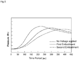
- FIG. 5 shows the pressure change history in a container when an air-fuel mixture having an equivalent ratio of 0.7 is filled in a closed container having a predetermined volume and is ignited at a container internal pressure of 1 MPa.
- a dotted line in the figure indicates the pressure change history in the container when a spark discharge is generated by a known ignition device (conventional example) in which potential increase control is not performed.
- a solid line indicates the pressure change history in the container when a spark discharge is generated by the ignition control in the first embodiment described above, and a dash-dot-dash line indicates the pressure change history in the container when a spark discharge is generated by the ignition control in the second embodiment.
- ignition timings (0 ms) at which spark discharges occur are aligned to compare the subsequent pressure change histories in the container.
- the increase in the pressure after the spark discharge is accelerated as compared with the conventional example.
- the increase in the pressure is further accelerated and the combustion period is further shortened as compared with that in the first embodiment. This may result from the fact that during the ignition control in the second embodiment, the ON state of the first switch 252 is maintained from before the generation of the spark discharge until after the generation of the spark discharge, and the electric field in the discharge region at the time of the spark discharge and during the subsequent combustion period is further enhanced.
- FIG. 6 schematically illustrates a configuration of an engine 100 including an ignition device 200 of the embodiment.
- the engine 100 is, for example, an engine using city gas supplied from a pipeline, as fuel, that is, a type of engine in which an air-fuel mixture of fuel gas G and air is supplied to a combustion chamber M described later and is ignited with a spark plug 230.
- the engine 100 includes an engine main body 10, an intake system 20, an exhaust system 30, an engine control unit (ECU) 50 serving as a control unit, and the ignition device 200 including the spark plug 230 and a response delay generation unit 260.
- the spark plug 230 includes a center electrode 231 and a ground electrode 232.
- the engine main body 10 is constituted of a cylinder head 70, and a cylinder block 80.
- the engine main body 10 includes a plurality of cylinders 11.
- FIG. 6 illustrates only one of the plurality of cylinders 11.
- Each of the cylinders 11 is communicated by the intake system 20 and also communicated by the exhaust system 30.
- the intake system 20 is constituted of an intake port 21 formed in the cylinder head 70 and an intake manifold 22.
- the exhaust system 30 is constituted of an exhaust port 31 and an exhaust manifold 32.
- the intake manifold 22 is provided with a gas injector 42.
- An intercooler, a main throttle, a turbocharger compressor, and the like (not illustrated) are arranged upstream of the intake system 20.
- a turbocharger turbine and the like (not illustrated) are arranged downstream of the exhaust manifold 32 in the exhaust system 30.
- the ECU 50 performs ignition control of the ignition device 200, and also controls the main throttle and the like so that an intake manifold pressure being the air flow rate reaches a target intake manifold pressure.
- a configuration of the cylinder head 70 will be further described with reference to FIG. 6 .
- the cylinder head 70 is arranged above the cylinder block 80.
- the cylinder head 70 is provided with an intake valve 71, an exhaust valve 72, and the spark plug 230 facing the combustion chamber M described later.
- the cylinder head 70 includes an attachment hole 73 for attaching the spark plug 230 to the cylinder head 70.
- a piston P is slidably housed in a cylindrical part 12 of the cylinder 11.
- the combustion chamber M is formed by an inner wall of the cylindrical part 12 of the cylinder 11, a lower surface of the cylinder head 70, and a top of the piston P, in the cylinder head 70.
- the intake manifold 22 is connected to a fuel supply pipe 41 via the gas injector 42, and is provided with an intake manifold pressure sensor 54.
- the fuel supply pipe 41 is provided with a fuel gas pressure sensor 55 configured to detect a fuel gas pressure and a fuel gas pressure regulator 56.
- the engine 100 is further provided with an engine speed sensor 51 configured to detect an engine speed Ne and an engine output sensor 52 configured to detect an engine output W.
- the engine speed sensor 51 and the engine output sensor 52 in addition to the gas injector 42, the fuel gas pressure sensor 55, and the fuel gas pressure regulator 56, are connected to the ECU 50. Not only the sensors and devices described above, but also various other sensors and devices may be connected to the ECU 50.
- a fuel injection rate map is set in the ECU 50.
- the fuel injection rate map represents a correlation among the engine speed Ne, the engine output W, and an instruction fuel injection rate Q being a fuel flow rate, and determines the instruction fuel injection rate Q with respect to the engine speed Ne and the engine output W.
- the ECU 50 controls the gas injector 42, based on the instruction fuel injection rate Q.
- a target intake manifold pressure map is further set in the ECU 50.
- the target intake manifold pressure map represents a correlation among the engine speed Ne, the engine output W, and a target intake manifold pressure Pi, and determines the target intake manifold pressure Pi with respect to the engine speed Ne and the engine output W.
- the ECU 50 controls the main throttle so that the intake manifold pressure reaches the target intake manifold pressure Pi.
- the ECU 50 controls the fuel gas pressure regulator 56, the gas injector 42, the main throttle, and the like to supply an air-fuel mixture obtained by mixing the fuel gas G and air to the intake manifold 22.
- the mixed gas is supplied to the combustion chamber M via the intake manifold 22 and is ignited by the spark plug 230.
- the ignition device 200 will be further described with reference to FIG. 7 and FIG. 8 in addition to FIG. 6 .
- the ignition device 200 includes the above-described ECU 50, spark plug 230, and the response delay generation unit 260 serving as a potential increase promotor in this embodiment.
- a voltage is applied for generating a spark discharge between the center electrode 231 and the ground electrode 232 via a terminal 231a coupled to the center electrode 231 of the spark plug 230.
- the response delay generation unit 260 is arranged between the ground electrode 232 and the GND.
- the response delay generation unit 260 has a function of maintaining the potential of the ground electrode 232 before the spark discharge in a high state, and generating a response delay in the potential change of the ground electrode 232 to enhance the electric field in the discharge region formed between the center electrode 231 and the ground electrode 232. With the potential on the ground electrode side being increased by the response delay generation unit 260 serving as a potential increase promotor, the electric field in a discharge region formed by the center electrode and the ground electrode is enhanced before the spark discharge occurs.
- the ignition device 200 includes an ignition coil including a primary coil 241, a secondary coil 242, and a core 243, an igniter 244, and a power source 245.
- the primary coil 241 is wound around the core 243.
- One end of the primary coil 241 is connected to the power source 245, and the other end of the primary coil 241 is connected to the igniter 244.
- the secondary coil 242 is wound around the core 243.
- One end of the secondary coil 242 is connected to the primary coil 241, and the other end of the secondary coil 242 is connected to the terminal 231a of the center electrode 231 in the spark plug 230.
- the igniter 244 is constituted of, for example, a transistor.
- the igniter 244 switches between supplying and stopping the supply of power from the power source 245 to the primary coil 241 by an energization signal from the ECU 50 described above.
- the above-described circuit is a circuit generally known as a circuit for applying a voltage to a spark plug, and various modifications can be assumed.
- the igniter 244 is constituted of a transistor.
- the present invention is not limited thereto, and the igniter 244 may be replaced with a point (contact) type distributor.
- the response delay generation unit 260 is arranged between the ground electrode 232 of the spark plug 230 and the GND.
- the response delay generation unit 260 has a function of preventing the potential of the ground electrode 232 from decreasing after a spark discharge occurs in the discharge region formed between the center electrode 231 and the ground electrode 232.
- the response delay generation unit 260 preferably includes a winding part (coil). The response delay generation unit 260 generates electromotive force by an excess response because of the provision of the winding part to realize the above function.
- FIG. 8 illustrates an example of a circuit constituting the response delay generation unit 260.
- the response delay generation unit 260 may include an inductor serving as a winding part. More specifically, it is possible to employ, as examples of a configuration of the response delay generation unit 260, a configuration in which the response delay generation unit 260 includes an inductor 261 (see FIG. 8(a) ), and a configuration in which the response delay generation unit 260 includes a resistor 262 and an inductor 263 arranged in series (see FIG.
- the response delay generation unit 260 includes a resistor 264 and an inductor 265 arranged in series and a capacitor 266 arranged in parallel with the resistor 264 and the inductor 265 (see FIG. 8(c) ).
- the configuration illustrated in FIG. 8(c) can be realized by, for example, a carbon film resistor.
- the carbon film resistor includes a pure carbon film tightly fixed on the surface of a porcelain bar by thermal decomposition at a high temperature and in a high vacuum, and provides a required resistance value obtained by forming a winding structure in which the carbon film is grooved in a spiral shape.
- the excess response characteristic of the response delay generation unit 260 is appropriately determined by experiments or the like.
- the spark plug 230 included in the ignition device 200 is arranged for each of the cylinders 11.
- the center electrode 231 and the ground electrode 232 are arranged at the leading end of the spark plug 230.
- the spark plug 230 further includes a conductive housing 234.
- the center electrode 231 is electrically coupled to the terminal 231a above the center electrode 231 via a copper core passing through the center of the spark plug 230 and being surrounded by an insulator.
- the ground electrode 232 is formed on the conductive housing 234.
- the housing 234 is made of, for example, a special nickel alloy.
- the housing 234 includes a threaded part 243a and a head part 243b.
- the threaded part 243a is screwed into the attachment hole 73 of the cylinder head 70.
- the ground electrode 232 is locked to one end of the threaded part 243a.
- the head part 243b is connected to the other end of the threaded part 243a.
- an approximately cylindrical insulator 74 is arranged between the attachment hole 73 of the cylinder head 70 and the housing 234 of the spark plug 230.
- the insulator 74 blocks the electrical conduction between the cylinder head 70 and the spark plug 230.
- the insulator 74 has an approximately cylindrical shape.
- the response delay generation unit 260 described above is arranged between the housing 234 of the spark plug 230 and the cylinder head 70.
- the housing 234 and the cylinder head 70 are connected via the response delay generation unit 260. With such a configuration, it is not necessary to process the spark plug 230 to form the response delay generation unit 260. Therefore, a commonly used spark plug can be employed as the spark plug 230 of the present embodiment.
- the present embodiment is generally configured as described above, and ignition control performed by the above-described ignition device 200 will be described below with reference to FIGS. 6 to 9 .
- the ECU 50 transmits an energization signal to the igniter 244 at a timing in consideration of the ignition time determined depending on the operating state of the engine so that the spark plug 230 generates a spark discharge.
- a current is supplied from the power source 245 to the primary coil 241 to form a magnetic field around the core 243.
- the energization signal to the igniter 244 is interrupted, and thus, the power supply from the power source 245 to the primary coil 241 is stopped.
- a negative secondary voltage is generated at the secondary coil 242 side by a mutual induction action.
- a voltage is applied to the discharge region formed between the center electrode 231 and the ground electrode 232 by the secondary voltage, and thus, a spark discharge occurs, and the air-fuel mixture compressed in the combustion chamber M is ignited.
- Such ignition control is repeatedly performed in synchronization with the ignition timing in each of the cylinders 11.
- FIG. 9(a) is a time chart illustrating a center electrode-side voltage, a ground electrode-side voltage, and a current when ignition control is performed by a known ignition device.
- FIG. 9(b) is a time chart illustrating a center electrode-side voltage, a ground electrode-side voltage, and a current when ignition control is performed by the ignition device 200 according to the present embodiment.
- BD a timing at which a spark discharge occurs.
- the ground electrode is always connected to the GND.
- the ground electrode-side voltage is maintained at approximately 0 V.
- the center electrode-side voltage required to generate a spark discharge is larger than the installation electrode-side voltage.
- a high current flows when a spark discharge is generated, as indicated by a dash-dot-dash line in FIG. 9(a) . Therefore, the center electrode and the ground electrode are likely to deteriorate.
- the response delay generation unit 260 is arranged between the ground electrode 232 and the GND.
- the ground electrode-side voltage does not decrease for a while as indicated by a dotted line in FIG. 9(b) . That is, a state where the electric field in the discharge region formed between the center electrode 231 and the ground electrode 232 is enhanced is maintained.
- the center electrode voltage for generating a spark discharge in the spark plug 230 can be reduced as compared with that in the known ignition device.
- the response delay generation unit 260 may be configured by any of the circuit examples of the response delay generation unit 260 illustrated in FIGS. 8(a) to 8(c) .
- the response delay generation unit 260 is a component for causing such a response delay.
- the present invention is not limited to the configuration described in the third embodiment described above, and various modifications can be assumed as long as they belong to the technical scope of the present invention.
- Other embodiments will be described below.
- the other embodiments described below differs from the third embodiment as above in the spark plug 230, the response delay generation unit 260, and the attachment structure of the spark plug 230 for the attachment hole 73 of the cylinder head 70, and the remaining configuration is common, a detailed description of the common features will thus be omitted.
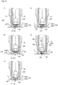
- FIG. 10(a) A fourth embodiment will be described with reference to FIG. 10(a) .
- the fourth embodiment illustrated in FIG. 10(a) is configured to realize the circuit example illustrated in FIG. 8(b) .
- the response delay generation unit 260 is constituted of the resistor 262 and the inductor 261 (winding part).
- the resistor 262 is arranged in the attachment hole 73 of the cylinder 70, and the resistor 262 has an approximately cylindrical shape.
- the spark plug 230 is attached to the attachment hole 73 via the resistor 262.
- the response delay generation unit 260 is configured by the inductor 261 and the resistor 262. In this case, it is not necessary to process the spark plug 230 for forming the response delay generation unit 260. Therefore, a commonly used spark plug can be used as is. The resistance value of the resistor 262 can be appropriately selected.
- a firth embodiment will be described with reference to FIG. 10(b) .
- the spark plug 230 is attached to the attachment hole 73 of the cylinder head 70 via the insulator 74.
- a gasket serving as the response delay generation unit 260 is arranged between the housing 234 of the spark plug 230 and the attachment hole 73 of the cylinder head 70. Airtightness between the spark plug 230 and the cylinder head is maintained by the response delay generation unit 260.
- a through hole is formed at the center (not illustrated), and the threaded part 243a of the spark plug 230 is inserted into the through hole.
- the housing 234 of the spark plug 230 and the cylinder head 70 are not directly connected, but are connected via the response delay generation unit 260.
- the response delay generation unit 260 may be configured such that the response delay generation unit 260 according to the present embodiment has a winding structure and an inductance, for example. With such a configuration, in the present embodiment, it is also possible to provide a similar operation and effect to those of the third embodiment described above. Further, in the present embodiment, similarly to the third and fourth embodiments, the processing of the spark plug 230 for forming the response delay generation unit 260 is unnecessary.
- the response delay generation unit 260 including the winding part is formed in a tubular shape.
- the threaded part 243a of the spark plug 230 is inserted into the response delay generation unit 260. That is, the spark plug 230 is attached to the attachment hole 73 of the cylinder head 70 via the response delay generation unit 260.
- the processing of the spark plug 230 for forming the response delay generation unit 260 is unnecessary.
- a seventh embodiment will be described with reference to FIG. 10(d) .
- the seventh embodiment illustrated in FIG. 10(d) differs from the third to sixth embodiments in configuration of the ground electrode 232.
- the ground electrode 232 is coupled to the housing 234 via the response delay generation unit 260.
- Such a response delay generation unit 260 may be configured by, for example, a small inductor, and it is possible to provide a similar operation and effect to those of the third embodiment described above.
- FIG. 10(e) An eighth embodiment will be described with reference to FIG. 10(e) .
- the center electrode 231 and the ground electrode 232 are electrically insulated from the housing 234.
- the terminal 231a of the center electrode 231 is connected to the above-described ignition coil, and the terminal 232a of the ground electrode 232 is connected to the cylinder head 70 via the response delay generation unit 260.
- the spark plug 230 according to the present embodiment is directly attached to the attachment hole 73 of the cylinder head 70, but the housing 234 and the ground electrode 232 are insulated.
- the spark plug 230 is improved, and thus, it is not necessary to make major changes to the cylinder head 70.
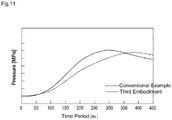
- FIG. 11 shows the pressure change history in a container when an air-fuel mixture having an equivalent ratio of 0.7 is filled in a closed container having a predetermined volume and is ignited at a container internal pressure of 1 MPa.
- a dotted line in the figure indicates the pressure change history in the container when the air-fuel mixture is ignited by a known ignition device (conventional example) not including the response delay generation unit 260.
- a solid line in the figure indicates the pressure change history in the container when the air-fuel mixture is ignited by the ignition device 200 of the third embodiment described above.
- ignition timings (0 ms) at which spark discharges occur are aligned to compare the subsequent pressure change histories.
- FIG. 11 indicates that in the third embodiment, the maintenance of the state where the electric field is enhanced even when combustion proceeds after the air-fuel mixture is ignited promotes the formation of the initial flame kernel, causing the combustion of the air-fuel mixture to proceed favorably, and shortening the combustion period.
- the present invention is not limited to the embodiments described above, and can include various modifications as long as they are included in the technical scope of the present invention.
- all the first through sixth embodiments describe examples in which the first through eighth embodiments are applied to a gas engine using city gas supplied from a pipeline, as fuel
- the present invention is not limited thereto.
- the present invention can be applied to any engine in which fuel ignites by a spark discharge, such as another gas engine using CNG or LNG as fuel, or a gasoline engine.
Landscapes
- Engineering & Computer Science (AREA)
- Chemical & Material Sciences (AREA)
- Combustion & Propulsion (AREA)
- Mechanical Engineering (AREA)
- General Engineering & Computer Science (AREA)
- Ignition Installations For Internal Combustion Engines (AREA)
Abstract
Description
- The present invention relates to an engine provided with an ignition device.
- In a known engine, a spark plug is arranged in a combustion chamber of an engine, a voltage generated by an ignition coil is applied to an electrode part including a center electrode and a ground electrode to cause an arc discharge in a discharge region of the electrode part, and thus, an air-fuel mixture supplied to the combustion chamber of the engine is ignited.
- For example, Patent Literature 1 (PTL 1) discloses an ignition device provided with a main electrode including a main high-voltage electrode and a main ground electrode, and an auxiliary electrode including an auxiliary high-voltage electrode and an auxiliary ground electrode. In the ignition device of PTL 1, the high voltage of a secondary coil connected to a battery is applied to the auxiliary electrode, and a switch is changed after a lapse of a predetermined time period to apply the high voltage to the main electrode to generate a spark discharge.
- Further, Patent Literature 2 (PTL 2) discloses an ignition device in which a terminal for observing a discharge voltage waveform is provided on one of discharge electrodes and a resistance (R3) for observing a discharge current waveform is provided on the other of the discharge electrodes, to easily calculate a discharge energy by a waveform observing means using an oscilloscope, in a spark discharge generator.
-
- PTL 1: Japanese Patent Application Laid-Open No.
2007-032349 - PTL 2: Japanese Patent Application Laid-Open No.
2005-185027 - In the known ignition devices disclosed in PTLs 1 and 2 described above, the ground electrode is always connected to the ground (GND), and the voltage on the ground electrode side is maintained at approximately 0 V. In such a configuration, there is a problem in that the voltage of the main electrode or the auxiliary electrode, which voltage is required for generating a spark discharge, is relatively large, and a high current flows when a spark discharge occurs, so that each of the electrodes is easily deteriorated.
- To solve the main technical problem described above, according to the present invention, there is provided an engine including an ignition device, which includes a center electrode, a ground electrode provided to correspond to the center electrode and connected to ground, and a potential increase promotor arranged between the ground and the ground electrode.
- The potential increase promotor includes a power source, to which the ground electrode provided to correspond to the center electrode is connected via a first switch, and a control unit that generates a spark discharge on the ignition device. The ground electrode is connected to the ground via a second switch. The control unit performs potential increase control, in which the control unit turns the first switch ON while keeping the second switch OFF to connect the ground electrode to the power source and increase a potential of the ground electrode. After performing the potential increase control, the control unit applies a voltage between the center electrode and the ground electrode while keeping the potential of the ground electrode increased to generate the spark discharge.
- The control unit may be configured to turn the first switch from ON to OFF before generating the spark discharge after turning the first switch ON to perform the potential increase control.
- Further, the control unit may be configured to generate the spark discharge while turning the first switch ON to perform the potential increase control.
- Further, the control unit may turn the second switch ON for a predetermined time period while keeping the first switch OFF after generating the spark discharge.
- The potential increase promotor may be a response delay generation unit provided between the ground and the ground electrode. In that case, the ground electrode provided to correspond to the center electrode and connected to the ground is included in the potential increase promotor.
- The response delay generation unit includes a winding part.
- The engine may further include a cylinder head including an attachment hole for attaching a spark plug including the center electrode and the ground electrode. In that case, the spark plug includes a conductive housing formed with the ground electrode, the spark plug is attached to the attachment hole via an insulator, and the housing and the cylinder head are connected via the response delay generation unit. The response delay generation unit may be formed as a gasket used when the spark plug is attached to the attachment hole.
- It is also possible that the engine further includes a cylinder head including an attachment hole for attaching a spark plug including the center electrode and the ground electrode, the response delay generation unit includes a resistor and a winding part arranged between the resistor and the cylinder head, and that the spark plug includes a conductive housing formed with the ground electrode and is attached to the attachment hole via the resistor.
- It is also possible that the engine further includes a cylinder head including an attachment hole for attaching a spark plug including the center electrode and the ground electrode, the spark plug including the center electrode and the ground electrode includes a conductive housing formed with the ground electrode, and the response delay generation unit is arranged between the housing and the attachment hole.
- It is also possible that the engine further includes a cylinder head including an attachment hole for attaching a spark plug including the center electrode and the ground electrode, the spark plug includes a conductive housing formed with the ground electrode and attached to the attachment hole, and the ground electrode is connected to the housing via the response delay generation unit.
- It is also possible that the engine further includes a cylinder head including an attachment hole for attaching a spark plug including the center electrode and the ground electrode, the spark plug includes a housing insulated from the center electrode and the ground electrode and is attached to the attachment hole via the housing, and a terminal of the ground electrode and the cylinder head are connected via the response delay generation unit.
- An engine according to the present invention includes an ignition device. The ignition device includes a center electrode, a ground electrode provided to correspond to the center electrode and connected to ground, and a potential increase promotor arranged between the ground and the ground electrode. With such configuration, an electric field in a discharge region formed by the center electrode and the ground electrode is enhanced before the spark discharge occurs by increasing the potential on the ground electrode side. As a result, the voltage at the start of spark discharge is suppressed, which makes it possible to suppress deterioration of an electrode part constituted of the center electrode and the ground electrode.
- The potential increase promotor of the engine according to the present invention includes a power source and a control unit. To the power source, the ground electrode provided to correspond to the center electrode is connected via a first switch. The ground electrode is connected to the ground via a second switch. The control unit performs potential increase control, in which the control unit turns the first switch ON while keeping the second switch OFF to connect the ground electrode to the power source and increase the potential of the ground electrode. After performing the potential increase control, the control unit applies a voltage between the center electrode and the ground electrode while keeping the potential of the ground electrode increased to generate the spark discharge. With such configuration, an electric field in a discharge region formed by the center electrode and the ground electrode is enhanced before the spark discharge occurs. As a result, it is possible to suppress deterioration of the electrode part constituted of the center electrode and the ground electrode.
- The potential increase promotor of the engine according to the present invention may include a center electrode, a ground electrode, and a response delay generation unit. The ground electrode is provided to correspond to the center electrode and is connected to the ground. The response delay generation unit is provided between the ground and the ground electrode. Thus, the electric field in a discharge region formed by the center electrode and the ground electrode is enhanced before spark ignition, and the voltage for generating a spark is reduced. As a result, it is possible to suppress deterioration of an electrode part constituted of the center electrode and the ground electrode. In addition, the electric field of the electrode part before the spark discharge is to be enhanced, so that the formation of an initial flame kernel when an air-fuel mixture is ignited is promoted to shorten the combustion period.
-
-
FIG. 1 is a schematic diagram of an engine according to a first embodiment of the present invention. -
FIG. 2 is a block diagram illustrating a simplified configuration of an ignition device arranged in the engine illustrated inFIG 1 . -
FIGS. 3(a) to 3(c) are time charts illustrating changes respectively in a secondary voltage, a first switch, and a second switch in ignition control according to the first embodiment. -
FIGS. 4(a) to 4(c) are time charts illustrating changes respectively in a secondary voltage, a first switch, and a second switch in ignition control according to a second embodiment. -
FIG. 5 is a graph illustrating pressure change histories when an air-fuel mixture is ignited for each of the first embodiment, the second embodiment, and the prior art. -
FIG. 6 is a schematic diagram of an engine including an ignition device according to a third embodiment. -
FIG. 7 is a block diagram illustrating a simplified configuration of the ignition device arranged in the engine illustrated inFIG 6 . -
FIGS. 8(a) to 8(c) are diagrams illustrating circuit examples of a response delay generation unit of the ignition device illustrated inFIG. 7 . -
FIGS. 9(a) and 9(b) are time charts illustrating a center electrode-side voltage, a ground electrode-side voltage, and a current when ignition control is performed respectively by a known ignition device and an ignition device according to each embodiment. -
FIGS. 10(a) to 10(e) are diagrams illustrating other embodiments for a spark plug and an attachment structure of the spark plug. -
FIG. 11 is a graph illustrating pressure change histories when an air-fuel mixture is ignited according to the third embodiment and the prior art. - A first embodiment of an engine configured according to the present invention will be described below in detail with reference to the accompanying drawings.
-
FIG. 1 schematically illustrates a configuration of anengine 100 in which anignition device 200 is arranged. Thegas engine 100 is, for example, an engine using city gas supplied from a pipeline, as fuel. Theengine 100 is a type of engine in which an air-fuel mixture of fuel gas G and air is supplied to a combustion chamber M described later and is ignited with aspark plug 230. - The
engine 100 includes an enginemain body 10, anintake system 20, anexhaust system 30, and theignition device 200 including an engine control unit (ECU) 50 serving as a control unit and thespark plug 230. Thespark plug 230 includes acenter electrode 231 and aground electrode 232. - The engine
main body 10 is constituted of acylinder head 70, and acylinder block 80. The enginemain body 10 includes a plurality ofcylinders 11.FIG. 1 illustrates only one of the plurality ofcylinders 11. Each of thecylinders 11 is communicated by theintake system 20 and also communicated by theexhaust system 30. Theintake system 20 is constituted of anintake port 21 formed in thecylinder head 70 and anintake manifold 22. Theexhaust system 30 is constituted of an exhaustport exhaust port 31 and anexhaust manifold 32. - The
intake manifold 22 is provided with agas injector 42. An intercooler, a main throttle, a turbocharger compressor, and the like (not illustrated) are arranged upstream of theintake system 20. A turbocharger turbine and the like (not illustrated) are arranged downstream of theexhaust manifold 32 in theexhaust system 30. - The
ECU 50 has a function of performing ignition control (described later) for theignition device 200, and controlling the main throttle and the like so that an intake manifold pressure being the air flow rate reaches a target intake manifold pressure, and controls theentire engine 100. - A configuration of the
cylinder head 70 will be further described with reference toFIG. 1 . - The
cylinder head 70 is arranged above thecylinder block 80. Thecylinder head 70 is provided with anintake valve 71, anexhaust valve 72, and thespark plug 230 facing the combustion chamber M described later. - A piston P is slidably housed in a
cylindrical part 12 of thecylinder 11. The combustion chamber M is formed by an inner wall of thecylindrical part 12 of thecylinder 11, a lower surface of thecylinder head 70, and a top of the piston P. - The
intake manifold 22 is connected to afuel supply pipe 41 via thegas injector 42, and is provided with an intakemanifold pressure sensor 54. Thefuel supply pipe 41 is provided with a fuelgas pressure sensor 55 configured to detect a fuel gas pressure and a fuelgas pressure regulator 56. - The
engine 100 is further provided with anengine speed sensor 51 configured to detect an engine speed Ne and anengine output sensor 52 configured to detect an engine output W. Theengine speed sensor 51 and theengine output sensor 52, in addition to thegas injector 42, the fuelgas pressure sensor 55, and the fuelgas pressure regulator 56, are connected to theECU 50. Not only the sensors and devices described above, but also various other sensors and devices may be connected to theECU 50. - A fuel injection rate map is set in the
ECU 50. The fuel injection rate map represents a correlation among the engine speed Ne, the engine output W, and an instruction fuel injection rate Q being a fuel flow rate, and determines the instruction fuel injection rate Q with respect to the engine speed Ne and the engine output W. TheECU 50 controls thegas injector 42, based on the instruction fuel injection rate Q. - A target intake manifold pressure map is further set in the
ECU 50. The target intake manifold pressure map represents a correlation among the engine speed Ne, the engine output W, and a target intake manifold pressure Pi, and determines the target intake manifold pressure Pi with respect to the engine speed Ne and the engine output W. TheECU 50 controls the main throttle so that the intake manifold pressure reaches the target intake manifold pressure Pi. - With the above configuration, the
ECU 50 controls the fuelgas pressure regulator 56, thegas injector 42, the main throttle, and the like to supply a mixed gas obtained by mixing the fuel gas G and air to theintake manifold 22. The mixed gas is supplied to the combustion chamber M via theintake manifold 22 and is ignited by thespark plug 230. - The
ignition device 200 will be further described with reference toFIG. 2 in addition toFIG. 1 . - The
ignition device 200 is constituted of the above-describedECU 50 andspark plug 230. Thespark plug 230 is arranged in thecylinder 11. - As illustrated in
FIG. 2 , theignition device 200 includes an ignition coil including aprimary coil 241, asecondary coil 242, and acore 243, and anigniter 244. Theprimary coil 241 is wound around thecore 243. One end of theprimary coil 241 is connected to apower source 245, and the other end of theprimary coil 241 is connected to theigniter 244. Thesecondary coil 242 is wound around thecore 243. One end of thesecondary coil 242 is connected to theprimary coil 241, and the other end of thesecondary coil 242 is connected to a terminal 231a of thecenter electrode 231. - The
igniter 244 is constituted of, for example, a transistor, and switches between supplying and stopping the supply of power from thepower source 245 to theprimary coil 241 by an energization signal from theECU 50 described above. The above-described high voltage application unit 240 is a circuit generally known as a circuit for applying a voltage to a spark plug, and various modifications can be assumed. For example, in the present embodiment, theigniter 244 is constituted of a transistor. However, the present invention is not limited thereto, and theigniter 244 may be replaced with a point (contact) type distributor. - The
ignition device 200 further includes apower source 251, afirst switch 252, and asecond switch 253. Theground electrode 232 of thespark plug 200 is connected to thepower source 251 via thefirst switch 252. Thefirst switch 252 connects and disconnects thepower source 251 and theground electrode 232. Theground electrode 232 is connected to the GND via thesecond switch 253. Thesecond switch 253 connects and disconnects theground electrode 232 and the GND. Thefirst switch 252 and thesecond switch 253 preferably comply with a high voltage and are capable of a high-speed response. Thefirst switch 252 and thesecond switch 253 are operated by an instruction signal from theECU 50, and are controlled at a predetermined appropriate timing. Thepower source 251, to which theground electrode 232 provided to correspond to thecenter electrode 231 as mentioned before is connected via thefirst switch 252, and theECU 50 arranged as a control unit generating a spark discharge on theignition device 200 constitute a potential increase promotor. With the potential on the ground electrode side being increased by the potential increase promotor, the electric field in a discharge region formed by the center electrode and the ground electrode is enhanced before a spark discharge occurs. - As illustrated in
FIG. 1 , thespark plug 230 has a threadedpart 233. The threadedpart 233 is used for attaching thespark plug 230 to anattachment hole 73 formed in thecylinder head 70. - The ignition control performed in the above-described
ignition device 200 will be described below with reference toFIG. 3. FIG. 3(a) illustrates a change in the secondary voltage from the ignition coil,FIG. 3(b) illustrates the ON/OFF state of thefirst switch 252, andFIG. 3(c) illustrates the ON/OFF state of thesecond switch 253. - When a spark discharge is generated with the
spark plug 230, theECU 50 performs the potential increase control of theground electrode 232. Specifically, firstly, as illustrated inFIG. 3(b) , while thesecond switch 253 is turned OFF, thefirst switch 252 of a ground electrodevoltage application unit 250 is turned ON for a predetermined period by an instruction signal from theECU 50. Thereafter, thefirst switch 252 is turned OFF before a voltage is applied to thespark plug 230 to generate a spark discharge (seeFIG. 3(b) ). Thus, the potential increase control is performed for theground electrode 232, and the state where the electric field formed by thecenter electrode 231 and theground electrode 232 is enhanced is maintained. - In parallel with the above-described potential increase control, an energization signal is sent from the
ECU 50 to theigniter 244 at a timing in consideration of an ignition time determined depending on an operating state of the engine. As a result, a current is supplied from thepower source 245 to theprimary coil 241 to form a magnetic field around thecore 243. As described above, even after thefirst switch 252 is turned OFF, the state where the electric field formed by thecenter electrode 231 and theground electrode 232 is enhanced continues. In this state, theECU 50 turns OFF the energization signal to theigniter 244. Thus, the power supply from thepower source 245 to theprimary coil 241 is stopped. When the power supply to theprimary coil 241 is stopped, an electromotive force is generated at thesecondary coil 242 side by the mutual induction action, and a negative secondary voltage is generated as illustrated inFIG. 3(a) . The timing at which the secondary voltage occurs is indicated by ST inFIG. 3 . A voltage is applied to the discharge region formed between thecenter electrode 231 and theground electrode 232 by the secondary voltage, a spark discharge occurs at a timing indicated by BD inFIG. 3 , and the air-fuel mixture compressed in the combustion chamber M is ignited. After the spark discharge occurs, thesecond switch 253 is turned ON for a predetermined time period (seeFIG. 3(c) ) to connect theground electrode 232 to the GND and set the potential of theground electrode 232 to the initial state (0 V). The time period when thesecond switch 253 is to be turned ON is stored in theECU 50 in advance, for example. Although not particularly limited, the time period when thesecond switch 253 is to be turned ON can be set between 1 and 10 msec. Such ignition control is repeatedly performed in synchronization with the ignition timing in each of thecylinders 11. - In the present embodiment, before a spark discharge is generated by the
spark plug 230, potential increase control for increasing the potential of theground electrode 232 is performed in advance, and the electric field in the discharge region formed between thecenter electrode 231 and theground electrode 232 is enhanced. Thus, the secondary voltage for generating the spark discharge in thespark plug 230 can be reduced as compared with the prior art, and as a result, deterioration of thecenter electrode 231 and theground electrode 232 can be suppressed. - The present invention is not limited to the configuration described in the first embodiment described above, and various modifications can be assumed. A second embodiment will be described below.
- The second embodiment is common to the first embodiment in that the configurations of the
engine 100 and theignition device 200 illustrated inFIG. 1 andFIG. 2 are employed, and the description of the common features is omitted. In the second embodiment, a timing of the instruction signal from theECU 50 to thefirst switch 252 and thesecond switch 253 is different from that in the first embodiment. Here, differences from the first embodiment will be mainly described with reference toFIG. 2 andFIG. 4 . - In the second embodiment, when a high voltage is applied to the
spark plug 230, firstly, thefirst switch 252 is turned ON by an instruction signal from theECU 50, and the ON state is maintained, as a result, potential increase control for maintaining the potential of theground electrode 232 in a high state is performed (seeFIG. 4(b) ). At this time, thesecond switch 253 is in an OFF state. As a result, the electric field in the discharge region formed by thecenter electrode 231 and theground electrode 232 is further enhanced as compared with that in the first embodiment. - An energization signal is sent from the
ECU 50 to theigniter 244 while the electric field formed by thecenter electrode 231 and theground electrode 232 is enhanced. TheECU 50 transmits an energization signal to theigniter 244 at a timing in consideration of the ignition time determined depending on an operating state of the engine. When the energization signal is sent from theECU 50 to theigniter 244, a current is supplied from thepower source 245 to theprimary coil 241, and a magnetic field is formed around thecore 243. After the predetermined time period has elapsed, theECU 50 turns OFF the energization signal to theigniter 244 at the timing indicated by ST inFIG. 4 . Thus, the power supply from thepower source 245 to theprimary coil 241 is stopped. When the power supply to theprimary coil 241 is stopped, an electromotive force is generated at thesecondary coil 242 side by the mutual induction action, and a negative secondary voltage is generated as illustrated inFIG. 4(a) . A spark discharge occurs in the discharge region formed between thecenter electrode 231 and theground electrode 232 by the secondary voltage at a timing indicated by BD inFIG. 4 , and the air-fuel mixture compressed in the combustion chamber M is ignited. After the spark discharge occurs, thefirst switch 252 is turned OFF, and at the same time, thesecond switch 253 is turned ON for a predetermined time period to connect theground electrode 232 to the ground and set the potential of theground electrode 232 to the initial state (0 V). In the present embodiment, thesecond switch 253 is turned ON at the same time as thefirst switch 252 is turned OFF, however, thesecond switch 253 may be turned ON after thefirst switch 252 is turned OFF. That is, thesecond switch 253 only needs to be ON for a predetermined time period while thefirst switch 252 is turned OFF. - In the second embodiment, similarly to the first embodiment, before a spark discharge is generated by the
spark plug 230, the potential increase control for increasing the potential of theground electrode 232 is also performed in advance, and the electric field in the discharge region formed between thecenter electrode 231 and theground electrode 232 is enhanced. Further, in the second embodiment, the ON state of thefirst switch 252 is maintained before and after the timing at which the spark discharge is generated, and therefore, the potential of theground electrode 232 is maintained in a high state even after the spark discharge, and the electric field in the discharge region is maintained in a more enhanced state. Therefore, the secondary voltage for generating a spark discharge in thespark plug 230 can be further reduced as compared with the prior art, and as a result, deterioration of thecenter electrode 231 and theground electrode 232 can be suppressed. - An effect of the ignition of the air-fuel mixture by the
ignition device 200 on the pressure change history in the combustion chamber M will be described with reference toFIG. 5 . Data shown inFIG. 5 shows the pressure change history in a container when an air-fuel mixture having an equivalent ratio of 0.7 is filled in a closed container having a predetermined volume and is ignited at a container internal pressure of 1 MPa. A dotted line in the figure indicates the pressure change history in the container when a spark discharge is generated by a known ignition device (conventional example) in which potential increase control is not performed. A solid line indicates the pressure change history in the container when a spark discharge is generated by the ignition control in the first embodiment described above, and a dash-dot-dash line indicates the pressure change history in the container when a spark discharge is generated by the ignition control in the second embodiment. InFIG. 5 , ignition timings (0 ms) at which spark discharges occur are aligned to compare the subsequent pressure change histories in the container. - As can be understood from
FIG. 5 , according to the ignition control in the first embodiment shown by the solid line, the increase in the pressure after the spark discharge is accelerated as compared with the conventional example. This indicates that the electric field between thecenter electrode 231 and theground electrode 232 is enhanced before the generation of the spark discharge, and the maintenance of the state where the electric field is enhanced when combustion proceeds after the air-fuel mixture is ignited promotes the formation of the initial flame kernel, causing the combustion of the air-fuel mixture to proceed favorably, and shortening the combustion period. - In the ignition control in the second embodiment indicated by the dash-dot-dash line, the increase in the pressure is further accelerated and the combustion period is further shortened as compared with that in the first embodiment. This may result from the fact that during the ignition control in the second embodiment, the ON state of the
first switch 252 is maintained from before the generation of the spark discharge until after the generation of the spark discharge, and the electric field in the discharge region at the time of the spark discharge and during the subsequent combustion period is further enhanced. - A first embodiment of an engine including an ignition device will be described below in detail with reference to the accompanying drawings.
-
FIG. 6 schematically illustrates a configuration of anengine 100 including anignition device 200 of the embodiment. Theengine 100 is, for example, an engine using city gas supplied from a pipeline, as fuel, that is, a type of engine in which an air-fuel mixture of fuel gas G and air is supplied to a combustion chamber M described later and is ignited with aspark plug 230. - The
engine 100 includes an enginemain body 10, anintake system 20, anexhaust system 30, an engine control unit (ECU) 50 serving as a control unit, and theignition device 200 including thespark plug 230 and a responsedelay generation unit 260. Thespark plug 230 includes acenter electrode 231 and aground electrode 232. - The engine
main body 10 is constituted of acylinder head 70, and acylinder block 80. The enginemain body 10 includes a plurality ofcylinders 11.FIG. 6 illustrates only one of the plurality ofcylinders 11. Each of thecylinders 11 is communicated by theintake system 20 and also communicated by theexhaust system 30. Theintake system 20 is constituted of anintake port 21 formed in thecylinder head 70 and anintake manifold 22. Theexhaust system 30 is constituted of anexhaust port 31 and anexhaust manifold 32. - The
intake manifold 22 is provided with agas injector 42. An intercooler, a main throttle, a turbocharger compressor, and the like (not illustrated) are arranged upstream of theintake system 20. A turbocharger turbine and the like (not illustrated) are arranged downstream of theexhaust manifold 32 in theexhaust system 30. - The
ECU 50 performs ignition control of theignition device 200, and also controls the main throttle and the like so that an intake manifold pressure being the air flow rate reaches a target intake manifold pressure. - A configuration of the
cylinder head 70 will be further described with reference toFIG. 6 . - The
cylinder head 70 is arranged above thecylinder block 80. Thecylinder head 70 is provided with anintake valve 71, anexhaust valve 72, and thespark plug 230 facing the combustion chamber M described later. Thecylinder head 70 includes anattachment hole 73 for attaching thespark plug 230 to thecylinder head 70. - A piston P is slidably housed in a
cylindrical part 12 of thecylinder 11. The combustion chamber M is formed by an inner wall of thecylindrical part 12 of thecylinder 11, a lower surface of thecylinder head 70, and a top of the piston P, in thecylinder head 70. - The
intake manifold 22 is connected to afuel supply pipe 41 via thegas injector 42, and is provided with an intakemanifold pressure sensor 54. Thefuel supply pipe 41 is provided with a fuelgas pressure sensor 55 configured to detect a fuel gas pressure and a fuelgas pressure regulator 56. - The
engine 100 is further provided with anengine speed sensor 51 configured to detect an engine speed Ne and anengine output sensor 52 configured to detect an engine output W. Theengine speed sensor 51 and theengine output sensor 52, in addition to thegas injector 42, the fuelgas pressure sensor 55, and the fuelgas pressure regulator 56, are connected to theECU 50. Not only the sensors and devices described above, but also various other sensors and devices may be connected to theECU 50. - A fuel injection rate map is set in the
ECU 50. The fuel injection rate map represents a correlation among the engine speed Ne, the engine output W, and an instruction fuel injection rate Q being a fuel flow rate, and determines the instruction fuel injection rate Q with respect to the engine speed Ne and the engine output W. TheECU 50 controls thegas injector 42, based on the instruction fuel injection rate Q. - A target intake manifold pressure map is further set in the
ECU 50. The target intake manifold pressure map represents a correlation among the engine speed Ne, the engine output W, and a target intake manifold pressure Pi, and determines the target intake manifold pressure Pi with respect to the engine speed Ne and the engine output W. TheECU 50 controls the main throttle so that the intake manifold pressure reaches the target intake manifold pressure Pi. - With the above configuration, the
ECU 50 controls the fuelgas pressure regulator 56, thegas injector 42, the main throttle, and the like to supply an air-fuel mixture obtained by mixing the fuel gas G and air to theintake manifold 22. The mixed gas is supplied to the combustion chamber M via theintake manifold 22 and is ignited by thespark plug 230. - The
ignition device 200 will be further described with reference toFIG. 7 andFIG. 8 in addition toFIG. 6 . - The
ignition device 200 includes the above-describedECU 50,spark plug 230, and the responsedelay generation unit 260 serving as a potential increase promotor in this embodiment. As generally illustrated inFIG. 1 andFIG. 2 , in theignition device 200, a voltage is applied for generating a spark discharge between thecenter electrode 231 and theground electrode 232 via aterminal 231a coupled to thecenter electrode 231 of thespark plug 230. The responsedelay generation unit 260 is arranged between theground electrode 232 and the GND. The responsedelay generation unit 260 has a function of maintaining the potential of theground electrode 232 before the spark discharge in a high state, and generating a response delay in the potential change of theground electrode 232 to enhance the electric field in the discharge region formed between thecenter electrode 231 and theground electrode 232. With the potential on the ground electrode side being increased by the responsedelay generation unit 260 serving as a potential increase promotor, the electric field in a discharge region formed by the center electrode and the ground electrode is enhanced before the spark discharge occurs. - As illustrated in
FIG. 7 , theignition device 200 includes an ignition coil including aprimary coil 241, asecondary coil 242, and acore 243, anigniter 244, and apower source 245. Theprimary coil 241 is wound around thecore 243. One end of theprimary coil 241 is connected to thepower source 245, and the other end of theprimary coil 241 is connected to theigniter 244. Thesecondary coil 242 is wound around thecore 243. One end of thesecondary coil 242 is connected to theprimary coil 241, and the other end of thesecondary coil 242 is connected to the terminal 231a of thecenter electrode 231 in thespark plug 230. - The
igniter 244 is constituted of, for example, a transistor. Theigniter 244 switches between supplying and stopping the supply of power from thepower source 245 to theprimary coil 241 by an energization signal from theECU 50 described above. The above-described circuit is a circuit generally known as a circuit for applying a voltage to a spark plug, and various modifications can be assumed. For example, in the present embodiment, theigniter 244 is constituted of a transistor. However, the present invention is not limited thereto, and theigniter 244 may be replaced with a point (contact) type distributor. - As illustrated in
FIG. 7 , the responsedelay generation unit 260 is arranged between theground electrode 232 of thespark plug 230 and the GND. The responsedelay generation unit 260 has a function of preventing the potential of theground electrode 232 from decreasing after a spark discharge occurs in the discharge region formed between thecenter electrode 231 and theground electrode 232. The responsedelay generation unit 260 preferably includes a winding part (coil). The responsedelay generation unit 260 generates electromotive force by an excess response because of the provision of the winding part to realize the above function. -
FIG. 8 illustrates an example of a circuit constituting the responsedelay generation unit 260. As illustrated inFIG. 8 , the responsedelay generation unit 260 may include an inductor serving as a winding part. More specifically, it is possible to employ, as examples of a configuration of the responsedelay generation unit 260, a configuration in which the responsedelay generation unit 260 includes an inductor 261 (seeFIG. 8(a) ), and a configuration in which the responsedelay generation unit 260 includes aresistor 262 and aninductor 263 arranged in series (seeFIG. 8(b) ), or a configuration in which the responsedelay generation unit 260 includes aresistor 264 and aninductor 265 arranged in series and acapacitor 266 arranged in parallel with theresistor 264 and the inductor 265 (seeFIG. 8(c) ). The configuration illustrated inFIG. 8(c) can be realized by, for example, a carbon film resistor. The carbon film resistor includes a pure carbon film tightly fixed on the surface of a porcelain bar by thermal decomposition at a high temperature and in a high vacuum, and provides a required resistance value obtained by forming a winding structure in which the carbon film is grooved in a spiral shape. When the inductance of the winding part, the resistance value of theresistors capacitor 266, and the like inFIGS. 8(a) to 8(c) are adjusted, it is possible to adjust the excess response characteristic of the responsedelay generation unit 260. The excess response characteristic of the responsedelay generation unit 260 is appropriately determined by experiments or the like. Thespark plug 230 included in theignition device 200 is arranged for each of thecylinders 11. - Returning to
FIG. 6 , a detailed configuration of thespark plug 230 and a configuration example of the responsedelay generation unit 260 will be described. Thecenter electrode 231 and theground electrode 232 are arranged at the leading end of thespark plug 230. Thespark plug 230 further includes aconductive housing 234. Thecenter electrode 231 is electrically coupled to the terminal 231a above thecenter electrode 231 via a copper core passing through the center of thespark plug 230 and being surrounded by an insulator. Theground electrode 232 is formed on theconductive housing 234. Thehousing 234 is made of, for example, a special nickel alloy. Thehousing 234 includes a threaded part 243a and a head part 243b. The threaded part 243a is screwed into theattachment hole 73 of thecylinder head 70. Theground electrode 232 is locked to one end of the threaded part 243a. The head part 243b is connected to the other end of the threaded part 243a. - In the present embodiment, an approximately
cylindrical insulator 74 is arranged between theattachment hole 73 of thecylinder head 70 and thehousing 234 of thespark plug 230. Theinsulator 74 blocks the electrical conduction between thecylinder head 70 and thespark plug 230. Theinsulator 74 has an approximately cylindrical shape. The responsedelay generation unit 260 described above is arranged between thehousing 234 of thespark plug 230 and thecylinder head 70. Thehousing 234 and thecylinder head 70 are connected via the responsedelay generation unit 260. With such a configuration, it is not necessary to process thespark plug 230 to form the responsedelay generation unit 260. Therefore, a commonly used spark plug can be employed as thespark plug 230 of the present embodiment. - The present embodiment is generally configured as described above, and ignition control performed by the above-described
ignition device 200 will be described below with reference toFIGS. 6 to 9 . - The
ECU 50 transmits an energization signal to theigniter 244 at a timing in consideration of the ignition time determined depending on the operating state of the engine so that thespark plug 230 generates a spark discharge. As a result, a current is supplied from thepower source 245 to theprimary coil 241 to form a magnetic field around thecore 243. Next, the energization signal to theigniter 244 is interrupted, and thus, the power supply from thepower source 245 to theprimary coil 241 is stopped. When the power supply to theprimary coil 241 is stopped, a negative secondary voltage is generated at thesecondary coil 242 side by a mutual induction action. A voltage is applied to the discharge region formed between thecenter electrode 231 and theground electrode 232 by the secondary voltage, and thus, a spark discharge occurs, and the air-fuel mixture compressed in the combustion chamber M is ignited. Such ignition control is repeatedly performed in synchronization with the ignition timing in each of thecylinders 11. -
FIG. 9(a) is a time chart illustrating a center electrode-side voltage, a ground electrode-side voltage, and a current when ignition control is performed by a known ignition device.FIG. 9(b) is a time chart illustrating a center electrode-side voltage, a ground electrode-side voltage, and a current when ignition control is performed by theignition device 200 according to the present embodiment. InFIG. 9 , a timing at which a spark discharge occurs is indicated by BD. - In the known ignition device, the ground electrode is always connected to the GND. Thus, as indicated by a dotted line in
FIG. 9(a) , in the known ignition device, the ground electrode-side voltage is maintained at approximately 0 V. In such a configuration, as indicated by a solid line inFIG. 9(a) , the center electrode-side voltage required to generate a spark discharge is larger than the installation electrode-side voltage. As a result, a high current flows when a spark discharge is generated, as indicated by a dash-dot-dash line inFIG. 9(a) . Therefore, the center electrode and the ground electrode are likely to deteriorate. - On the other hand, in the
ignition device 200 according to the present embodiment, the responsedelay generation unit 260 is arranged between theground electrode 232 and the GND. Thus, after a spark discharge occurs and the air-fuel mixture is ignited, the ground electrode-side voltage does not decrease for a while as indicated by a dotted line inFIG. 9(b) . That is, a state where the electric field in the discharge region formed between thecenter electrode 231 and theground electrode 232 is enhanced is maintained. When ignition control is performed in such a configuration, as indicated by solid lines inFIG. 9 , the center electrode voltage for generating a spark discharge in thespark plug 230 can be reduced as compared with that in the known ignition device. As a result, it is possible to suppress the value of the current flowing when a spark discharge is generated, and also suppress deterioration of thecenter electrode 231 and theground electrode 232. The responsedelay generation unit 260 according to the present embodiment may be configured by any of the circuit examples of the responsedelay generation unit 260 illustrated inFIGS. 8(a) to 8(c) . - As illustrated in
FIG. 9(b) , in theignition device 200 according to the present embodiment, after the spark discharge occurs, the ground electrode-side voltage decreases slowly, not suddenly. This phenomenon is called response delay. The responsedelay generation unit 260 is a component for causing such a response delay. - The present invention is not limited to the configuration described in the third embodiment described above, and various modifications can be assumed as long as they belong to the technical scope of the present invention. Other embodiments will be described below. The other embodiments described below differs from the third embodiment as above in the
spark plug 230, the responsedelay generation unit 260, and the attachment structure of thespark plug 230 for theattachment hole 73 of thecylinder head 70, and the remaining configuration is common, a detailed description of the common features will thus be omitted. - A fourth embodiment will be described with reference to
FIG. 10(a) . The fourth embodiment illustrated inFIG. 10(a) is configured to realize the circuit example illustrated inFIG. 8(b) . The responsedelay generation unit 260 is constituted of theresistor 262 and the inductor 261 (winding part). Theresistor 262 is arranged in theattachment hole 73 of thecylinder 70, and theresistor 262 has an approximately cylindrical shape. Thespark plug 230 is attached to theattachment hole 73 via theresistor 262. - In the fourth embodiment, the response
delay generation unit 260 is configured by theinductor 261 and theresistor 262. In this case, it is not necessary to process thespark plug 230 for forming the responsedelay generation unit 260. Therefore, a commonly used spark plug can be used as is. The resistance value of theresistor 262 can be appropriately selected. - A firth embodiment will be described with reference to
FIG. 10(b) . In the fifth embodiment illustrated inFIG. 10(b) , similarly to the third embodiment, thespark plug 230 is attached to theattachment hole 73 of thecylinder head 70 via theinsulator 74. At this time, a gasket serving as the responsedelay generation unit 260 is arranged between thehousing 234 of thespark plug 230 and theattachment hole 73 of thecylinder head 70. Airtightness between thespark plug 230 and the cylinder head is maintained by the responsedelay generation unit 260. In the responsedelay generation unit 260 according to the present embodiment, a through hole is formed at the center (not illustrated), and the threaded part 243a of thespark plug 230 is inserted into the through hole. Thus, thehousing 234 of thespark plug 230 and thecylinder head 70 are not directly connected, but are connected via the responsedelay generation unit 260. It may be configured such that the responsedelay generation unit 260 according to the present embodiment has a winding structure and an inductance, for example. With such a configuration, in the present embodiment, it is also possible to provide a similar operation and effect to those of the third embodiment described above. Further, in the present embodiment, similarly to the third and fourth embodiments, the processing of thespark plug 230 for forming the responsedelay generation unit 260 is unnecessary. - The sixth embodiment will be described with reference to
FIG. 10(c) . In the sixth embodiment illustrated inFIG. 10(c) , the responsedelay generation unit 260 including the winding part is formed in a tubular shape. The threaded part 243a of thespark plug 230 is inserted into the responsedelay generation unit 260. That is, thespark plug 230 is attached to theattachment hole 73 of thecylinder head 70 via the responsedelay generation unit 260. With such a configuration, it is possible to provide a similar operation and effect to those of the third embodiment described above. Further, in the present embodiment, similarly to the third through fifth embodiments, the processing of thespark plug 230 for forming the responsedelay generation unit 260 is unnecessary. - A seventh embodiment will be described with reference to
FIG. 10(d) . The seventh embodiment illustrated inFIG. 10(d) differs from the third to sixth embodiments in configuration of theground electrode 232. In the present embodiment, theground electrode 232 is coupled to thehousing 234 via the responsedelay generation unit 260. Such a responsedelay generation unit 260 may be configured by, for example, a small inductor, and it is possible to provide a similar operation and effect to those of the third embodiment described above. - An eighth embodiment will be described with reference to
FIG. 10(e) . In the eighth embodiment illustrated inFIG. 10(e) , thecenter electrode 231 and theground electrode 232 are electrically insulated from thehousing 234. The terminal 231a of thecenter electrode 231 is connected to the above-described ignition coil, and the terminal 232a of theground electrode 232 is connected to thecylinder head 70 via the responsedelay generation unit 260. Thespark plug 230 according to the present embodiment is directly attached to theattachment hole 73 of thecylinder head 70, but thehousing 234 and theground electrode 232 are insulated. In the present embodiment, it is also possible to provide a similar operation and effect to those of the third embodiment described above. In the seventh and eighth embodiments described above, thespark plug 230 is improved, and thus, it is not necessary to make major changes to thecylinder head 70. - An effect of the ignition of the air-fuel mixture by the
ignition device 200 on the pressure change history in the combustion chamber M will be described with reference toFIG. 11 . Data shown inFIG. 11 shows the pressure change history in a container when an air-fuel mixture having an equivalent ratio of 0.7 is filled in a closed container having a predetermined volume and is ignited at a container internal pressure of 1 MPa. A dotted line in the figure indicates the pressure change history in the container when the air-fuel mixture is ignited by a known ignition device (conventional example) not including the responsedelay generation unit 260. A solid line in the figure indicates the pressure change history in the container when the air-fuel mixture is ignited by theignition device 200 of the third embodiment described above. InFIG. 10 , ignition timings (0 ms) at which spark discharges occur are aligned to compare the subsequent pressure change histories. - As understood from
FIG. 11 , in the third embodiment indicated by the solid line, the increase in the pressure after ignition is accelerated as compared with the conventional example. This may result from the fact that electric field between thecenter electrode 231 and theground electrode 232 is enhanced by the responsedelay generation unit 260.FIG. 11 indicates that in the third embodiment, the maintenance of the state where the electric field is enhanced even when combustion proceeds after the air-fuel mixture is ignited promotes the formation of the initial flame kernel, causing the combustion of the air-fuel mixture to proceed favorably, and shortening the combustion period. - The present invention is not limited to the embodiments described above, and can include various modifications as long as they are included in the technical scope of the present invention. Although all the first through sixth embodiments describe examples in which the first through eighth embodiments are applied to a gas engine using city gas supplied from a pipeline, as fuel, the present invention is not limited thereto. For example, the present invention can be applied to any engine in which fuel ignites by a spark discharge, such as another gas engine using CNG or LNG as fuel, or a gasoline engine.
-
- 10
- Engine main body
- 11
- Cylinder
- 20
- Intake system
- 21
- Intake port
- 22
- Intake manifold
- 30
- Exhaust system
- 31
- Exhaust port
- 32
- Exhaust manifold
- 41
- Fuel supply path
- 42
- Gas injector
- 50
- ECU (control unit)
- 70
- Cylinder head
- 80
- Cylinder block
- 100
- Engine
- 200
- Ignition device
- 230
- Spark plug
- 231
- Center electrode
- 232
- Ground electrode
- 234
- Housing
- 250
- Ground electrode voltage application unit
- 251
- Power source
- 252
- First switch
- 253
- Second switch
- 260
- Response delay generation unit
- 261, 263, 265
- Inductor (winding part)
- 262, 264
- Resistor
- 266
- Capacitor
Claims (13)
- An engine comprising an ignition device,
the ignition device including:a center electrode;a ground electrode provided to correspond to the center electrode and connected to ground; anda potential increase promotor arranged between the ground and the ground electrode. - The engine according to claim 1,
wherein the potential increase promotor includes a power source, to which the ground electrode provided to correspond to the center electrode is connected via a first switch, and a control unit that generates a spark discharge on the ignition device,
wherein the ground electrode is connected to the ground via a second switch, and
wherein the control unit performs potential increase control, in which the control unit turns the first switch ON while keeping the second switch OFF to connect the ground electrode to the power source and increase a potential of the ground electrode, and, after performing the potential increase control, applies a voltage between the center electrode and the ground electrode while keeping the potential of the ground electrode increased to generate the spark discharge. - The engine according to claim 2, wherein the control unit turns the first switch from ON to OFF before generating the spark discharge after turning the first switch ON to perform the potential increase control.
- The engine according to claim 2, wherein the control unit generates the spark discharge while turning the first switch ON to perform the potential increase control.
- The engine according to claim 3 or claim 4, wherein the control unit turns the second switch ON for a predetermined time period while keeping the first switch OFF after generating the spark discharge.
- The engine according to claim 1,
wherein the potential increase promotor includes a response delay generation unit provided between the ground and the ground electrode, and
wherein the ground electrode provided to correspond to the center electrode and connected to the ground is included in the potential increase promotor. - The engine according to claim 6, wherein the response delay generation unit includes a winding part.
- The engine according to claim 6 or claim 7, further comprising a cylinder head including an attachment hole for attaching a spark plug including the center electrode and the ground electrode,
wherein the spark plug includes a conductive housing formed with the ground electrode, the spark plug is attached to the attachment hole via an insulator, and the housing and the cylinder head are connected via the response delay generation unit. - The engine according to claim 8, wherein the response delay generation unit is formed as a gasket used when the spark plug is attached to the attachment hole.
- The engine according to claim 6, further comprising a cylinder head including an attachment hole for attaching a spark plug including the center electrode and the ground electrode,
wherein the response delay generation unit includes a resistor and a winding part arranged between the resistor and the cylinder head, and
wherein the spark plug includes a conductive housing formed with the ground electrode, and is attached to the attachment hole via the resistor. - The engine according to claim 6 or claim 7, further comprising a cylinder head including an attachment hole for attaching a spark plug including the center electrode and the ground electrode,
wherein the spark plug including the center electrode and the ground electrode includes a conductive housing formed with the ground electrode, and
wherein the response delay generation unit is arranged between the housing and the attachment hole. - The engine according to claim 6 or claim 7, further comprising a cylinder head including an attachment hole for attaching a spark plug including the center electrode and the ground electrode,
wherein the spark plug includes a conductive housing formed with the ground electrode and attached to the attachment hole, and
wherein the ground electrode is connected to the housing via the response delay generation unit. - The engine according to claim 6 or claim 7, further comprising a cylinder head including an attachment hole for attaching a spark plug including the center electrode and the ground electrode,
wherein the spark plug includes a housing insulated from the center electrode and the ground electrode, and is attached to the attachment hole via the housing, and
wherein a terminal of the ground electrode and the cylinder head are connected via the response delay generation unit.
Applications Claiming Priority (3)
| Application Number | Priority Date | Filing Date | Title |
|---|---|---|---|
| JP2017209777A JP2019082134A (en) | 2017-10-30 | 2017-10-30 | engine |
| JP2017209776A JP6886658B2 (en) | 2017-10-30 | 2017-10-30 | engine |
| PCT/JP2018/038844 WO2019087799A1 (en) | 2017-10-30 | 2018-10-18 | Engine |
Publications (2)
| Publication Number | Publication Date |
|---|---|
| EP3705714A1 true EP3705714A1 (en) | 2020-09-09 |
| EP3705714A4 EP3705714A4 (en) | 2021-11-17 |
Family
ID=66333103
Family Applications (1)
| Application Number | Title | Priority Date | Filing Date |
|---|---|---|---|
| EP18872591.5A Withdrawn EP3705714A4 (en) | 2017-10-30 | 2018-10-18 | Engine |
Country Status (3)
| Country | Link |
|---|---|
| EP (1) | EP3705714A4 (en) |
| CN (1) | CN111247331A (en) |
| WO (1) | WO2019087799A1 (en) |
Family Cites Families (11)
| Publication number | Priority date | Publication date | Assignee | Title |
|---|---|---|---|---|
| JPS60118378U (en) * | 1984-01-18 | 1985-08-10 | 阪神エレクトリツク株式会社 | Capacitive discharge ignition system |
| JPH08273950A (en) * | 1995-04-03 | 1996-10-18 | Mitsubishi Electric Corp | Ignition coil for internal combustion engine |
| JP2001032758A (en) * | 1999-07-22 | 2001-02-06 | Ngk Spark Plug Co Ltd | Ignition device for internal combustion engine |
| JP3940622B2 (en) * | 2001-11-29 | 2007-07-04 | 日本特殊陶業株式会社 | Ignition device for internal combustion engine |
| JP2003172241A (en) * | 2001-12-04 | 2003-06-20 | Mitsubishi Electric Corp | Misfire detection device for internal combustion engine |
| JP2005185027A (en) | 2003-12-22 | 2005-07-07 | Hiroshi Shirahama | Beam-form spark discharge generating apparatus |
| JP2007032349A (en) | 2005-07-25 | 2007-02-08 | Denso Corp | Ignition device for internal combustion engine |
| JP2010096109A (en) * | 2008-10-17 | 2010-04-30 | Denso Corp | Ignition device |
| JP5423417B2 (en) * | 2010-01-20 | 2014-02-19 | 株式会社デンソー | High frequency plasma ignition device |
| EP2687714A4 (en) * | 2011-03-14 | 2014-11-05 | Imagineering Inc | Internal combustion engine |
| DE102016003791A1 (en) * | 2016-03-29 | 2017-10-05 | Rosenberger Hochfrequenztechnik Gmbh & Co. Kg | Ignition device for igniting an air-fuel mixture in a combustion chamber |
-
2018
- 2018-10-18 CN CN201880061537.5A patent/CN111247331A/en active Pending
- 2018-10-18 WO PCT/JP2018/038844 patent/WO2019087799A1/en not_active Ceased
- 2018-10-18 EP EP18872591.5A patent/EP3705714A4/en not_active Withdrawn
Also Published As
| Publication number | Publication date |
|---|---|
| WO2019087799A1 (en) | 2019-05-09 |
| EP3705714A4 (en) | 2021-11-17 |
| CN111247331A (en) | 2020-06-05 |
Similar Documents
| Publication | Publication Date | Title |
|---|---|---|
| US9151258B2 (en) | Integrated fuel injector igniters having force generating assemblies for injecting and igniting fuel and associated methods of use and manufacture | |
| CN101910615A (en) | Plasma Jet Spark Plug Ignition Control | |
| US10830201B2 (en) | Ignition system having a high-frequency plasma-enhanced ignition spark of a spark plug, including an antechamber, and a method associated therewith | |
| EP3374626B1 (en) | Method and apparatus to control an ignition system | |
| JP2008303841A (en) | Internal combustion engine and control device for internal combustion engine | |
| CN106471243B (en) | Dual-signal coaxial cavity resonator plasma generator and method therefor | |
| JP5658729B2 (en) | Ignition system | |
| US8847494B2 (en) | Ignition system for plasma jet ignition plug | |
| JP6536209B2 (en) | Ignition device for internal combustion engine | |
| EP3374627B1 (en) | Method and apparatus to control an ignition system | |
| CN100356643C (en) | Ignition system of internal combustion engine and method of ignition of fuel discharged into combustion chamber | |
| JP5907149B2 (en) | Control device for internal combustion engine | |
| KR20110105240A (en) | Ignition apparatus of internal combustion engine with multiple ignition coils and spark plugs | |
| WO2019087799A1 (en) | Engine | |
| JP6467849B2 (en) | Ignition device for internal combustion engine | |
| US9133812B2 (en) | Ignition apparatus and ignition system | |
| JP6886658B2 (en) | engine | |
| JP2019082134A (en) | engine | |
| GB2051230A (en) | Ignition System for an Internal Combustion Engine Employing Fuel Injection | |
| US20230417210A1 (en) | Ignition device for use in internal combustion engine | |
| JP7863458B2 (en) | Ignition system for internal combustion engines | |
| JP5584484B2 (en) | Control method for spark ignition internal combustion engine | |
| JP2024150974A (en) | Ignition device for internal combustion engine and internal combustion engine | |
| JP2023135718A (en) | igniter | |
| JP2019082177A (en) | Ignition device for internal combustion engine |
Legal Events
| Date | Code | Title | Description |
|---|---|---|---|
| STAA | Information on the status of an ep patent application or granted ep patent |
Free format text: STATUS: THE INTERNATIONAL PUBLICATION HAS BEEN MADE |
|
| PUAI | Public reference made under article 153(3) epc to a published international application that has entered the european phase |
Free format text: ORIGINAL CODE: 0009012 |
|
| STAA | Information on the status of an ep patent application or granted ep patent |
Free format text: STATUS: REQUEST FOR EXAMINATION WAS MADE |
|
| 17P | Request for examination filed |
Effective date: 20200514 |
|
| AK | Designated contracting states |
Kind code of ref document: A1 Designated state(s): AL AT BE BG CH CY CZ DE DK EE ES FI FR GB GR HR HU IE IS IT LI LT LU LV MC MK MT NL NO PL PT RO RS SE SI SK SM TR |
|
| AX | Request for extension of the european patent |
Extension state: BA ME |
|
| DAV | Request for validation of the european patent (deleted) | ||
| DAX | Request for extension of the european patent (deleted) | ||
| RIC1 | Information provided on ipc code assigned before grant |
Ipc: F02P 15/00 20060101AFI20210706BHEP Ipc: F02P 3/04 20060101ALI20210706BHEP Ipc: H01T 13/32 20060101ALI20210706BHEP Ipc: H01T 13/40 20060101ALI20210706BHEP Ipc: F02P 9/00 20060101ALN20210706BHEP Ipc: H01T 13/44 20060101ALN20210706BHEP |
|
| A4 | Supplementary search report drawn up and despatched |
Effective date: 20211015 |
|
| RIC1 | Information provided on ipc code assigned before grant |
Ipc: H01T 13/44 20060101ALN20211011BHEP Ipc: F02P 9/00 20060101ALN20211011BHEP Ipc: H01T 13/40 20060101ALI20211011BHEP Ipc: H01T 13/32 20060101ALI20211011BHEP Ipc: F02P 3/04 20060101ALI20211011BHEP Ipc: F02P 15/00 20060101AFI20211011BHEP |
|
| STAA | Information on the status of an ep patent application or granted ep patent |
Free format text: STATUS: THE APPLICATION IS DEEMED TO BE WITHDRAWN |
|
| 18D | Application deemed to be withdrawn |
Effective date: 20220514 |