EP3705677B1 - Transmission for an architectural-structure covering - Google Patents
Transmission for an architectural-structure covering Download PDFInfo
- Publication number
- EP3705677B1 EP3705677B1 EP20160735.5A EP20160735A EP3705677B1 EP 3705677 B1 EP3705677 B1 EP 3705677B1 EP 20160735 A EP20160735 A EP 20160735A EP 3705677 B1 EP3705677 B1 EP 3705677B1
- Authority
- EP
- European Patent Office
- Prior art keywords
- transmission
- shaft
- driven shaft
- covering
- housing
- Prior art date
- Legal status (The legal status is an assumption and is not a legal conclusion. Google has not performed a legal analysis and makes no representation as to the accuracy of the status listed.)
- Active
Links
Images


Classifications
-
- E—FIXED CONSTRUCTIONS
- E06—DOORS, WINDOWS, SHUTTERS, OR ROLLER BLINDS IN GENERAL; LADDERS
- E06B—FIXED OR MOVABLE CLOSURES FOR OPENINGS IN BUILDINGS, VEHICLES, FENCES OR LIKE ENCLOSURES IN GENERAL, e.g. DOORS, WINDOWS, BLINDS, GATES
- E06B9/00—Screening or protective devices for wall or similar openings, with or without operating or securing mechanisms; Closures of similar construction
- E06B9/24—Screens or other constructions affording protection against light, especially against sunshine; Similar screens for privacy or appearance; Slat blinds
-
- E—FIXED CONSTRUCTIONS
- E06—DOORS, WINDOWS, SHUTTERS, OR ROLLER BLINDS IN GENERAL; LADDERS
- E06B—FIXED OR MOVABLE CLOSURES FOR OPENINGS IN BUILDINGS, VEHICLES, FENCES OR LIKE ENCLOSURES IN GENERAL, e.g. DOORS, WINDOWS, BLINDS, GATES
- E06B9/00—Screening or protective devices for wall or similar openings, with or without operating or securing mechanisms; Closures of similar construction
- E06B9/24—Screens or other constructions affording protection against light, especially against sunshine; Similar screens for privacy or appearance; Slat blinds
- E06B9/26—Lamellar or like blinds, e.g. venetian blinds
- E06B9/28—Lamellar or like blinds, e.g. venetian blinds with horizontal lamellae, e.g. non-liftable
- E06B9/30—Lamellar or like blinds, e.g. venetian blinds with horizontal lamellae, e.g. non-liftable liftable
- E06B9/32—Operating, guiding, or securing devices therefor
- E06B9/322—Details of operating devices, e.g. pulleys, brakes, spring drums, drives
-
- F—MECHANICAL ENGINEERING; LIGHTING; HEATING; WEAPONS; BLASTING
- F16—ENGINEERING ELEMENTS AND UNITS; GENERAL MEASURES FOR PRODUCING AND MAINTAINING EFFECTIVE FUNCTIONING OF MACHINES OR INSTALLATIONS; THERMAL INSULATION IN GENERAL
- F16H—GEARING
- F16H57/00—General details of gearing
- F16H57/0018—Shaft assemblies for gearings
- F16H57/0025—Shaft assemblies for gearings with gearing elements rigidly connected to a shaft, e.g. securing gears or pulleys by specially adapted splines, keys or methods
-
- F—MECHANICAL ENGINEERING; LIGHTING; HEATING; WEAPONS; BLASTING
- F16—ENGINEERING ELEMENTS AND UNITS; GENERAL MEASURES FOR PRODUCING AND MAINTAINING EFFECTIVE FUNCTIONING OF MACHINES OR INSTALLATIONS; THERMAL INSULATION IN GENERAL
- F16H—GEARING
- F16H9/00—Gearings for conveying rotary motion with variable gear ratio, or for reversing rotary motion, by endless flexible members
- F16H9/02—Gearings for conveying rotary motion with variable gear ratio, or for reversing rotary motion, by endless flexible members without members having orbital motion
Definitions
- the present disclosure relates generally to the field of architectural-structure coverings, and more particularly to a transmission used in combination with an operating system for moving a covering of the architectural-structure covering between extended and retracted positions.
- Architectural-structure coverings may selectively cover an architectural structure such as, for example, a window, a doorway, a skylight, a hallway, an archway, a portion of a wall, etc. (collectively an architectural structure without the intent to limit).
- Architectural-structure coverings may include a covering that can be extendable and retractable, for example, vertically extendable or retractable (e.g., able to be lowered or raised, respectively, in a vertical direction) between an extended position and a retracted position for obscuring and exposing the underlying architectural structure.
- the architectural-structure covering may further include a bottom rail attached to a lower edge of the covering. The bottom rail may be utilized to add weight along the lower edge of the covering to encourage the covering to drop by gravity during deployment.
- the architectural-structure covering may also include a headrail for concealing a top portion of the architectural-structure covering.
- some architectural-structure coverings include a rotatable member (e.g., a rod or a roller). In use, rotation of the rotatable member in a first direction may retract the covering while rotation of the rotatable member in a second, opposite direction may extend the covering.
- the covering of the architectural-structure covering may be gathered, stacked or accumulated onto the bottom rail as the bottom rail is being retracted such that in the fully retracted position, the covering is positioned adjacent to the rotatable member.
- some retractable coverings include a plurality of slats that are raised or lowered by lift cords that are wrapped about or unwrapped from the rotatable member.
- the lift cords are coupled to the covering, the bottom rail, and the rotatable member.
- rotation of the rotatable member in a first direction wraps the lift cords about the rotatable member causing the bottom rail and hence the covering to retract or raise adjacent to the rotatable member
- rotation in a second direction causes the lift cords to unwrap about the rotatable member causing the bottom rail and hence the covering to move or lower in an extended configuration.
- rotation of the rotatable member generally causes movement of the covering of the architectural-structure covering.
- an operating system may be operably coupled to the rotatable member.
- the operating system may be operatively associated with an operating element, for example, a cord, a chain, a tilt wand, or the like.
- the operating element may be manipulated by a human operator to move the covering between the extended and retracted positions.
- the operating system may include a motorized controller to lower or raise a covering portion.
- a motorized drive motor e.g., an electric motor
- the operating element may include a hand-held remote or the like.
- the covering may be moved by gripping the bottom rail of the architectural-structure covering.
- the covering when the covering is in the fully extended position, only the bottom rail is supported by, for example, the lift cords.
- the rest of the weight of the covering is supported by, for example, ladder tape which has tilt cables running to, and supported by, the head rail. Since the weight of the covering not resting on the bottom rail is supported by the head rail (via the ladder tapes), this weight need not be overcome when raising the covering. Only the weight of the bottom rail, and the weight of each successive portion of the covering resting on the bottom rail as it comes into contact with the bottom rail as the covering is raised, need to be overcome.
- the lift cord and the ladder tapes exchange loads as the covering is raised and lowered.
- the ladder tapes do practically all of the supporting when the covering is extended.
- the weight is shifted from the ladder tapes onto the lift cords as each successive portion of the covering is picked up by the rising bottom rail and thus is no longer supported by the ladder tapes.
- the implication is that the least amount of force is required to start raising the covering when in the fully extended position, and also the least amount of force is required to maintain the covering in the extended position. Progressively larger force is required to lift and to maintain the position of the covering as the covering is raised until a maximum amount of force is reached at the topmost position, where the covering is fully retracted.
- the force required to raise the covering varies directly and approximately linearly with the raising of the covering, increasing from a minimum when the covering is fully lowered to a maximum when the covering is fully raised. This same force also varies directly and approximately linearly with the size and weight of the covering.
- the operating system may include a motor such as, for example, a spring motor to provide additional force to balance the weight of the covering so that, when a user raises or lowers the covering, the covering easily moves in the required direction.
- the motor can ensure that the covering maintains its desired position when the user stops raising or lowering the covering.
- the spring motor preferably is a constant force motor, but as has been observed, the force required to balance the covering varies as the covering is raised and lowered, with the greatest force required in the retracted position and the least force required in the extended position. For this reason, it is usually desirable to incorporate a transmission so that the desired amount of force is provided at all positions of the covering.
- One known transmission includes, inter alia , a housing, a drive shaft, a driven shaft, and a transmission cord or element.
- the driven shaft may be in the form of a tapered driven shaft arranged and configured so that the output force is greater when the covering is in the raised position and the output force is less when the covering is in the lowered position.
- a transmission for use with an architectural-structure covering the transmission being arranged and configured to move a covering of the architectural-structure covering between an extended position and a retracted position is disclosed.
- the transmission assists with balancing the forces associated with raising and lowering the covering of the architectural-structure covering.
- the transmission may be operatively coupled to a motor such as, for example, a spring motor, which provides additional force required to raise and lower the covering, and to maintain the desired position of the covering.
- the spring motor is often arranged and configured as a constant force motor, the transmission may be arranged and configured to alter the supplied force to balance the supplied force against the varying forces of the covering as the covering is raised and lowered.
- the transmission may be incorporated into an architectural-structure covering to assist with balancing the forces associated with raising and lowering the covering of the architectural-structure covering.
- the transmission may be operatively coupled to a motor such as, for example, a spring motor, which provides additional force required to raise and lower the covering, and to maintain a desired position of the covering.
- a motor such as, for example, a spring motor
- the transmission may be arranged and configured to adjust the supplied force of the motor to balance the supplied force against the varying forces of the covering as the covering is raised and lowered.
- the transmission 100 includes a housing 110, a drive shaft 120, a driven shaft 140, and a transmission element, cord, or the like 160 (element and cord used interchangeably without the intent to limit).
- the drive shaft 120 is arranged and configured to couple to a power module (e.g., spring motor) (not shown) for driving or rotating the drive shaft 120.
- the power module e.g., spring motor
- the power module may include a housing, a spring, a storage spool, and a power spool. In use, the power spool mates with and drives the drive shaft 120 of the transmission 100.
- the transmission of the present disclosure is not limited to the particular details of the power module (e.g., spring motor) and thus the specific details of the power module (e.g., spring motor) are omitted for the sake of brevity. Additional information on the structure and operation of the power module (e.g., spring motor) and the components thereof, can be found in United States Patent No. 6,536,503 entitled Modular Transport System for Coverings for Architectural Openings".
- the drive shaft 120 is non-rotatably coupled to the power module (e.g., spring motor).
- the drive shaft 120 may include a non-circular end 122 for coupling to the power module (e.g., spring motor).
- the power module e.g., spring motor
- the driven shaft 140 includes a first end 142, a second end 144, and an intermediate tapered shaft portion.
- the tapered shaft portion includes a plurality of threads for receiving the transmission cord 160, as will be described in greater detail below.
- the driven shaft may include a smooth, intermediate shaft portion.
- the driven shaft 140 is positioned parallel to the drive shaft 120 within the housing 110, with the first end 142 positioned adjacent to a first end 124 of the drive shaft 120 and the second end 144 positioned adjacent to a second end 128 of the drive shaft 120.
- the second end 144 of the driven shaft 140 has a diameter larger than the diameter of the first end 142.
- first gear 150 couples to a second gear 152, which is coupled to a first shaft 154 (e.g., the first shaft 154 may also be referred to herein as an input/output shaft).
- An intermediate cap 156 may be provided to support and align the ends of the components.
- a series of bushings 170 may be incorporated at the ends of the drive shaft 120 and at the ends of the driven shaft 140 to facilitate rotation of the drive shaft 120 and the driven shaft 140.
- the transmission 100 has three rotating parts - the drive shaft 120, the driven shaft 140 (e.g., tapered driven shaft), and the first or input/output shaft 154.
- the drive shaft 120 is operatively coupled to the driven shaft 140 via the transmission cord 160.
- the drive shaft 120 includes a small hole 126 adjacent to the first end 124 of the drive shaft 120 for receiving a first end of the transmission cord 160.
- the second end 144 of the driven shaft 140 includes a small hole (not shown) for receiving a second end of the transmission cord 160.
- the transmission cord 160 is wound onto the driven shaft 140 (e.g., tapered driven shaft) when the covering is in the extended position.
- the spring motor (not shown) rotates and the drive shaft 120 rotates in a first direction, which, in turn, winds the transmission cord 160 onto the drive shaft 120, causing the driven shaft 140 (e.g., tapered driven shaft) to rotate.
- Rotation of the driven shaft 140 causes the first gear 150 to rotate, which, in turn, rotates the second gear 152, which rotates the first shaft 154, which rotates a rotatable member (not shown) and winds the lift cords.
- the lift cords are coupled to the covering, the bottom rail, and the rotatable member so that, in use, rotation of the rotatable member in a first direction wraps the lift cords about the rotatable member causing the bottom rail and hence the covering to retract or raise relative to the rotatable member.
- the lift cords are unwound, causing the rotatable member to rotate in the opposite direction.
- This rotates the first shaft 154, the second gear 152, and the first gear 150 of the transmission 100 in the opposite direction, which causes the driven shaft 140 (e.g., tapered driven shaft) to rotate so as to wind up the transmission cord 160 onto itself, which rotates the drive shaft 120 and rotates or winds the spring motor.
- the spring motor assists in raising the covering. That is, as the covering is lowered, the weight of the covering and the force of gravity are used to wind up the spring in the power module so that the unwinding of the spring may assist in the raising of the covering.
- the transmission 100 may also include an end cover 112 coupled to the housing 110.
- the end cover 112 may be coupled to the housing 110 by fasteners.
- the end cover 112 includes an opening 114 through which the first shaft 154 is accessible so that the first shaft 154 may be operatively coupled with the rotatable member of the architectural-structure covering.
- the output force of the transmission 100 is greater when the covering is in the retracted position to assist with (e.g., maintain and/or lift) the covering when the greatest amount of force or weight is present on the bottom rail of the covering and the output force of the transmission 100 is less when the covering is in the extended position (e.g., when the least amount of weight or force is present on the bottom rail). Additional information on the structure and operation of the transmission 100 and the components thereof, can be found in United States Patent No. 6,536,503 entitled Modular Transport System for Coverings for Architectural Openings".
- the transmission of FIG. 1 preferably requires the application of lubricant (e.g., grease) between the moving parts to perform.
- lubricant e.g., grease
- the first and second gears 150, 152 are generally manufactured from zinc, generally using a low precision manufacturing process.
- the transmission 200 is arranged and configured as a stand-alone unit or module, the stand-alone unit or module including, inter alia , the housing 210, the drive shaft 220, the driven shaft 240, the transmission element or cord 260, and the geared assembly 300.
- the transmission 200 can be installed as a unit or module and coupled to other components on opposite ends thereof such as, for example, a spring motor and a rotatable member.
- the second end 224 may include an end portion arranged and configured so that the second end 224 is rotatably coupled to the intermediate member or plate 310, as will be described in greater detail below.
- the second end 224 may include a circular-shaped end portion.
- the drive shaft 220 is operatively coupled to the driven shaft 240 via the transmission cord 260.
- the drive shaft 220 may include a small hole (not shown) adjacent to the first end 222 of the drive shaft 220 for receiving a first end of the transmission cord 260.
- the second end 244 of the driven shaft 240 may include a small hole (not shown) for receiving a second end of the transmission cord 260, although other mechanisms for coupling the transmission cord 260 to the drive shaft 220 and the driven shaft 240 are envisioned.
- the transmission cord 260 can be pre-knotted and positioned (e.g., slid) onto the driven shaft 240. In use, the knotted transmission cord 260 can be held in position by the first gear 320 and/or the intermediate member or plate 310 when assembled.
- the first gear 320 may be separately formed and coupled to the driven shaft 240 (e.g., non-integrally formed with the driven shaft 240).
- the first and second gears 320, 330 may be manufactured using a precision manufacturing process, thus allowing the first and second gears 320, 330 to be manufactured as precision gears such as, for example, helical gears as opposed to, for example, less precise die cast gears made from zinc.
- the second end 244 of the driven shaft 240 may include a recess 245 for receiving and rotatably locking to the non-circular end portion 324 of the geared shaft 322, although other suitable mechanism for coupling the driven shaft 240 to the geared shaft 322 are envisioned. In use, rotation from the driven shaft 240 is transferred to the geared shaft 322, and hence the first gear 320, and vice-versa.
- first and second gears 320, 330 By positioning the first and second gears 320, 330 on the intermediate member or plate 310, alignment of the first and second gears 320, 330 with each other, and with other associated components, is assured. Additionally, by positioning the first and second gears 320, 330 on the intermediate member or plate 310 and coupling the intermediate member or plate 310 directly to the housing 210, forces on the driven shaft 240 from, for example, the architectural-structure covering (e.g., weight) are transferred from the intermediate member or plate 310 directly to the housing 210 thus minimizing the forces on the drive shaft 220 and the driven shaft 240 and thus binding of the drive shaft 220 and the driven shaft 240 is substantially minimized. Moreover, the disclosed arrangement enables a single geared assembly to be created, which is then coupled to the housing 210, thus simplifying manufacturing and assembly of the transmission.
- the architectural-structure covering e.g., weight
- an improved transmission 200 is provided.
- the transmission 200 of the present disclosure is easier and faster to assemble as compared to known, prior art transmissions.
- the first and second gears 320, 330 may be manufactured using a precision manufacturing process, thus allowing the first and second gears 320, 330 to be manufactured as precision gears such as, for example, helical gears as opposed to, for example, less precise die cast gears made from zinc.
- the first and second gears 320, 330, along with the first shaft 340 and the intermediate member or plate 310 and end cover 216 can be manufactured and assembled as a geared assembly and thereafter, coupled to the housing 210 thus saving additional time and reducing complexity of the assembly process.
- the first and second gears 320, 330 may be manufactured from plastic, although other suitable materials are envisioned.
- a transmission may be contained within a fully contained module or housing.
- the transmission may be readily interconnected to satisfy the requirements of a multitude of different architectural-structure coverings.
- Each module may be easily and readily installed, mounted, replaced, removed, and interconnected within the architectural-structure covering.
- Each housing may include a mounting mechanism for its module and removal of the housing also removes all the individual components contained therein.
- individual modules may be removed and replaced with other modules which fit in the same location and have the same method of interconnection and installation, but which have different performance characteristics.
- interchangeable transmission modules may have different transmission ratios, or may even be a different type of transmission than the ones disclosed in this specification such a gear-type transmission.
Landscapes
- Engineering & Computer Science (AREA)
- Structural Engineering (AREA)
- Architecture (AREA)
- Civil Engineering (AREA)
- Transmission Devices (AREA)
- Power-Operated Mechanisms For Wings (AREA)
- Shafts, Cranks, Connecting Bars, And Related Bearings (AREA)
- Tents Or Canopies (AREA)
Description
- The present disclosure relates generally to the field of architectural-structure coverings, and more particularly to a transmission used in combination with an operating system for moving a covering of the architectural-structure covering between extended and retracted positions.
- Architectural-structure coverings may selectively cover an architectural structure such as, for example, a window, a doorway, a skylight, a hallway, an archway, a portion of a wall, etc. (collectively an architectural structure without the intent to limit). Architectural-structure coverings may include a covering that can be extendable and retractable, for example, vertically extendable or retractable (e.g., able to be lowered or raised, respectively, in a vertical direction) between an extended position and a retracted position for obscuring and exposing the underlying architectural structure. The architectural-structure covering may further include a bottom rail attached to a lower edge of the covering. The bottom rail may be utilized to add weight along the lower edge of the covering to encourage the covering to drop by gravity during deployment. In addition, the architectural-structure covering may also include a headrail for concealing a top portion of the architectural-structure covering.
- To move the covering between the extended and retracted positions, some architectural-structure coverings include a rotatable member (e.g., a rod or a roller). In use, rotation of the rotatable member in a first direction may retract the covering while rotation of the rotatable member in a second, opposite direction may extend the covering. In various embodiments, the covering of the architectural-structure covering may be gathered, stacked or accumulated onto the bottom rail as the bottom rail is being retracted such that in the fully retracted position, the covering is positioned adjacent to the rotatable member. For example, some retractable coverings include a plurality of slats that are raised or lowered by lift cords that are wrapped about or unwrapped from the rotatable member. The lift cords are coupled to the covering, the bottom rail, and the rotatable member. In use, rotation of the rotatable member in a first direction wraps the lift cords about the rotatable member causing the bottom rail and hence the covering to retract or raise adjacent to the rotatable member, while rotation in a second direction causes the lift cords to unwrap about the rotatable member causing the bottom rail and hence the covering to move or lower in an extended configuration. As such, rotation of the rotatable member generally causes movement of the covering of the architectural-structure covering. To actuate movement of the rotatable member, and thus the covering of the architectural-structure covering, an operating system may be operably coupled to the rotatable member.
- The operating system may be operatively associated with an operating element, for example, a cord, a chain, a tilt wand, or the like. The operating element may be manipulated by a human operator to move the covering between the extended and retracted positions. Alternatively, the operating system may include a motorized controller to lower or raise a covering portion. For example, a motorized drive motor (e.g., an electric motor) can be provided to move the covering portion between an extended position, and a retracted position. In this embodiment, the operating element may include a hand-held remote or the like. In alternate embodiments, the covering may be moved by gripping the bottom rail of the architectural-structure covering.
- As will be appreciated by one of ordinary skill in the art, when raising the covering of the architectural-structure covering, at first only the bottom rail is being raised and the amount of force required is small. As the bottom rail is raised further, more of the covering becomes gathered, stacked or accumulated on top of the bottom rail and thus progressively more force is required to continue to raise the covering. The largest amount of force will be required at the very top when literally the entire, or most of the covering is being raised. By the same token, the greatest amount of force will be required to maintain the covering in its position, as one is fighting against the weight of the entire covering, or most of the covering.
- In contrast, when the covering is in the fully extended position, only the bottom rail is supported by, for example, the lift cords. The rest of the weight of the covering is supported by, for example, ladder tape which has tilt cables running to, and supported by, the head rail. Since the weight of the covering not resting on the bottom rail is supported by the head rail (via the ladder tapes), this weight need not be overcome when raising the covering. Only the weight of the bottom rail, and the weight of each successive portion of the covering resting on the bottom rail as it comes into contact with the bottom rail as the covering is raised, need to be overcome.
- In essence, the lift cord and the ladder tapes exchange loads as the covering is raised and lowered. The ladder tapes do practically all of the supporting when the covering is extended. As the covering is raised, the weight is shifted from the ladder tapes onto the lift cords as each successive portion of the covering is picked up by the rising bottom rail and thus is no longer supported by the ladder tapes. The implication is that the least amount of force is required to start raising the covering when in the fully extended position, and also the least amount of force is required to maintain the covering in the extended position. Progressively larger force is required to lift and to maintain the position of the covering as the covering is raised until a maximum amount of force is reached at the topmost position, where the covering is fully retracted.
- The force required to raise the covering varies directly and approximately linearly with the raising of the covering, increasing from a minimum when the covering is fully lowered to a maximum when the covering is fully raised. This same force also varies directly and approximately linearly with the size and weight of the covering.
- As a result, operating systems may be incorporated to assist with the added forces associated with raising the covering of an architectural-structure covering. In some embodiments, the operating system may include a motor such as, for example, a spring motor to provide additional force to balance the weight of the covering so that, when a user raises or lowers the covering, the covering easily moves in the required direction. Similarly, the motor can ensure that the covering maintains its desired position when the user stops raising or lowering the covering. The spring motor preferably is a constant force motor, but as has been observed, the force required to balance the covering varies as the covering is raised and lowered, with the greatest force required in the retracted position and the least force required in the extended position. For this reason, it is usually desirable to incorporate a transmission so that the desired amount of force is provided at all positions of the covering.
- One known transmission, described in
United States Patent No. 6,536,503 , includes, inter alia, a housing, a drive shaft, a driven shaft, and a transmission cord or element. In use, as will be described in greater detail, the driven shaft may be in the form of a tapered driven shaft arranged and configured so that the output force is greater when the covering is in the raised position and the output force is less when the covering is in the lowered position. - It is with respect to these and other considerations that the present improvements may be useful.
- The invention is defined by the claims. Any aspects, embodiments and examples of the present disclosure which do not fall under the scope of the appended claims do not form part of the invention and are merely provided for illustrative purposes. Disclosed herein is a transmission for use with an architectural-structure covering, the transmission being arranged and configured to move a covering of the architectural-structure covering between an extended position and a retracted position is disclosed. In use, the transmission assists with balancing the forces associated with raising and lowering the covering of the architectural-structure covering. In use, the transmission may be operatively coupled to a motor such as, for example, a spring motor, which provides additional force required to raise and lower the covering, and to maintain the desired position of the covering. As the spring motor is often arranged and configured as a constant force motor, the transmission may be arranged and configured to alter the supplied force to balance the supplied force against the varying forces of the covering as the covering is raised and lowered.
-
-
FIG. 1 is an exploded, perspective view of a known transmission; -
FIG. 2 is an exploded, perspective view of an example embodiment of an improved transmission in accordance with aspects of the present disclosure; and -
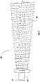
FIG. 3 is a partial side view of an example embodiment of a driven shaft that may be used with the transmission shown inFIG. 2 . - Embodiments of an example, illustrative transmission for architectural-structure coverings in accordance with various separate and independent principles of the present disclosure will now be described more fully hereinafter with reference to the accompanying drawings, in which embodiments of the present disclosure are presented. The transmission of the present disclosure may, however, be embodied in many different forms and should not be construed as being limited to the embodiments set forth herein. Rather, these embodiments are provided so that this disclosure will convey certain aspects of the transmission to those skilled in the art. In the drawings, like numbers refer to like elements throughout unless otherwise noted.
- In use, the transmission may be incorporated into an architectural-structure covering to assist with balancing the forces associated with raising and lowering the covering of the architectural-structure covering. In some embodiments, the transmission may be operatively coupled to a motor such as, for example, a spring motor, which provides additional force required to raise and lower the covering, and to maintain a desired position of the covering. As the spring motor is often arranged and configured as a constant force motor, the transmission may be arranged and configured to adjust the supplied force of the motor to balance the supplied force against the varying forces of the covering as the covering is raised and lowered.
- One known transmission used to affect the desired operation of the covering is illustrated in
FIG. 1 . As illustrated, thetransmission 100 includes ahousing 110, adrive shaft 120, a drivenshaft 140, and a transmission element, cord, or the like 160 (element and cord used interchangeably without the intent to limit). In use, thedrive shaft 120 is arranged and configured to couple to a power module (e.g., spring motor) (not shown) for driving or rotating thedrive shaft 120. For example, in one example embodiment, the power module (e.g., spring motor) may include a housing, a spring, a storage spool, and a power spool. In use, the power spool mates with and drives thedrive shaft 120 of thetransmission 100. It should be understood that the transmission of the present disclosure is not limited to the particular details of the power module (e.g., spring motor) and thus the specific details of the power module (e.g., spring motor) are omitted for the sake of brevity. Additional information on the structure and operation of the power module (e.g., spring motor) and the components thereof, can be found inUnited States Patent No. 6,536,503 entitled Modular Transport System for Coverings for Architectural Openings". - As mentioned, the
drive shaft 120 is non-rotatably coupled to the power module (e.g., spring motor). For example, as illustrated, thedrive shaft 120 may include anon-circular end 122 for coupling to the power module (e.g., spring motor). In this manner, the power module can mate with thedrive shaft 120 of thetransmission 100 so that rotation from the power module is transferred to thedrive shaft 120, and vice-versa. - The driven
shaft 140 includes afirst end 142, asecond end 144, and an intermediate tapered shaft portion. As illustrated, in one embodiment, the tapered shaft portion includes a plurality of threads for receiving thetransmission cord 160, as will be described in greater detail below. However, it should be understood that the driven shaft may include a smooth, intermediate shaft portion. In use, the drivenshaft 140 is positioned parallel to thedrive shaft 120 within thehousing 110, with thefirst end 142 positioned adjacent to afirst end 124 of thedrive shaft 120 and thesecond end 144 positioned adjacent to asecond end 128 of thedrive shaft 120. In one embodiment, as a result of the tapered shaft portion, thesecond end 144 of the drivenshaft 140 has a diameter larger than the diameter of thefirst end 142. By providing a tapered shaft, the output force of thetransmission 100 can be adjusted so that, for example, the output force can be greater when the covering is in the retracted position and less when the covering is in the extended position. - At the
second end 144 of the driven shaft 140 (e.g., tapered driven shaft) is afirst gear 150. Thefirst gear 150 couples to asecond gear 152, which is coupled to a first shaft 154 (e.g., thefirst shaft 154 may also be referred to herein as an input/output shaft). Anintermediate cap 156 may be provided to support and align the ends of the components. In addition, a series ofbushings 170 may be incorporated at the ends of thedrive shaft 120 and at the ends of the drivenshaft 140 to facilitate rotation of thedrive shaft 120 and the drivenshaft 140. - In use, the
transmission 100 has three rotating parts - thedrive shaft 120, the driven shaft 140 (e.g., tapered driven shaft), and the first or input/output shaft 154. Thedrive shaft 120 is operatively coupled to the drivenshaft 140 via thetransmission cord 160. For example, as illustrated, thedrive shaft 120 includes asmall hole 126 adjacent to thefirst end 124 of thedrive shaft 120 for receiving a first end of thetransmission cord 160. In addition, thesecond end 144 of the drivenshaft 140 includes a small hole (not shown) for receiving a second end of thetransmission cord 160. In use, thetransmission cord 160 is wound onto the driven shaft 140 (e.g., tapered driven shaft) when the covering is in the extended position. As the covering is raised, the spring motor (not shown) rotates and thedrive shaft 120 rotates in a first direction, which, in turn, winds thetransmission cord 160 onto thedrive shaft 120, causing the driven shaft 140 (e.g., tapered driven shaft) to rotate. Rotation of the drivenshaft 140 causes thefirst gear 150 to rotate, which, in turn, rotates thesecond gear 152, which rotates thefirst shaft 154, which rotates a rotatable member (not shown) and winds the lift cords. As previously mentioned, the lift cords are coupled to the covering, the bottom rail, and the rotatable member so that, in use, rotation of the rotatable member in a first direction wraps the lift cords about the rotatable member causing the bottom rail and hence the covering to retract or raise relative to the rotatable member. Conversely, when the covering is extended, the lift cords are unwound, causing the rotatable member to rotate in the opposite direction. This in turn, rotates thefirst shaft 154, thesecond gear 152, and thefirst gear 150 of thetransmission 100 in the opposite direction, which causes the driven shaft 140 (e.g., tapered driven shaft) to rotate so as to wind up thetransmission cord 160 onto itself, which rotates thedrive shaft 120 and rotates or winds the spring motor. In use, the spring motor assists in raising the covering. That is, as the covering is lowered, the weight of the covering and the force of gravity are used to wind up the spring in the power module so that the unwinding of the spring may assist in the raising of the covering. - As illustrated, the
transmission 100 may also include anend cover 112 coupled to thehousing 110. Theend cover 112 may be coupled to thehousing 110 by fasteners. In use, theend cover 112 includes anopening 114 through which thefirst shaft 154 is accessible so that thefirst shaft 154 may be operatively coupled with the rotatable member of the architectural-structure covering. - In use, by utilizing a tapered shaft for the driven
shaft 140, the output force of thetransmission 100 is greater when the covering is in the retracted position to assist with (e.g., maintain and/or lift) the covering when the greatest amount of force or weight is present on the bottom rail of the covering and the output force of thetransmission 100 is less when the covering is in the extended position (e.g., when the least amount of weight or force is present on the bottom rail). Additional information on the structure and operation of thetransmission 100 and the components thereof, can be found inUnited States Patent No. 6,536,503 entitled Modular Transport System for Coverings for Architectural Openings". - One common issue with the transmission of
FIG. 1 is that the number and complex arrangement of the components generally results in a time-consuming assembly process, generally resulting in high cost, high production time, and potentially reduced quality. Additionally, the transmission ofFIG. 1 preferably requires the application of lubricant (e.g., grease) between the moving parts to perform. Additionally, the first andsecond gears - Referring to
FIG. 2 , in accordance with one aspect of the present disclosure, thetransmission 200 includes ahousing 210, adrive shaft 220, a drivenshaft 240, a transmission element orcord 260, and a gearedassembly 300. In the illustrated embodiment, thehousing 210 includes afirst end 212 for coupling to a motor such as, for example, a spring motor (not shown), asecond end 214 for coupling to anend cover 216 as will be described in greater detail below, and aninternal cavity 218 for housing thedrive shaft 220, the drivenshaft 240, thetransmission cord 260, and the gearedassembly 300. In one embodiment, thetransmission 200 is arranged and configured as a stand-alone unit or module, the stand-alone unit or module including, inter alia, thehousing 210, thedrive shaft 220, the drivenshaft 240, the transmission element orcord 260, and the gearedassembly 300. In this manner, as will be described in greater detail, thetransmission 200 can be installed as a unit or module and coupled to other components on opposite ends thereof such as, for example, a spring motor and a rotatable member. - In the illustrated embodiment, the
drive shaft 220 includes afirst end 222, asecond end 224, and acentral portion 226 extending between the first and second ends 222, 224. As illustrated, thecentral portion 226 may have a cylindrical shape although other shapes are envisioned such as, for example, a tapered shape depending on the desired transmission ratio, as will be described in greater detail below. Thefirst end 222 includes anend portion 223 such as, for example, a non-circular end portion, for coupling to the power module (e.g., spring motor) for driving or rotating thedrive shaft 220 so that rotation from the power module is transferred to thedrive shaft 220, and vice-versa, although other suitable coupling mechanisms for connecting thedrive shaft 220 to the spring motor may be incorporated. Thesecond end 224 may include an end portion arranged and configured so that thesecond end 224 is rotatably coupled to the intermediate member orplate 310, as will be described in greater detail below. For example, in one embodiment, thesecond end 224 may include a circular-shaped end portion. - The driven
shaft 240 includes afirst end 242, asecond end 244, and a tapered shaft portion 246 (e.g., the drivenshaft 240 may also be referred to herein as a tapered driven shaft). By providing a taperedshaft portion 246, the output force of thetransmission 200 can be adjusted so that, for example, the output force can be greater when the covering is in the retracted position and less when the covering is in the extended position. As illustrated, in one embodiment, the taperedshaft portion 246 includes a plurality of threads for receiving thetransmission cord 260, as will be described in greater detail below. However, it should be understood that the driven shaft may include a smooth, intermediate shaft portion. In use, the drivenshaft 240 is positioned parallel to thedrive shaft 220 within thehousing 210. Thedrive shaft 220 is operatively coupled to the drivenshaft 240 via thetransmission cord 260. For example, similar to thetransmission 100 described above in connection withFIG. 1 , thedrive shaft 220 may include a small hole (not shown) adjacent to thefirst end 222 of thedrive shaft 220 for receiving a first end of thetransmission cord 260. In addition, thesecond end 244 of the drivenshaft 240 may include a small hole (not shown) for receiving a second end of thetransmission cord 260, although other mechanisms for coupling thetransmission cord 260 to thedrive shaft 220 and the drivenshaft 240 are envisioned. Alternatively, as will be described in greater detail below, thetransmission cord 260 can be pre-knotted and positioned (e.g., slid) onto the drivenshaft 240. In use, the knottedtransmission cord 260 can be held in position by thefirst gear 320 and/or the intermediate member orplate 310 when assembled. - In use, rotation of the
drive shaft 220 causes thetransmission cord 260 to wind and unwind, thus resulting in rotation of the drivenshaft 240, and vice-versa. In this manner, similar to thetransmission 100 described above in connection withFIG. 1 , thetransmission cord 260 is wound onto the tapered drivenshaft 240 when the covering is in the extended position. As the covering is raised, the spring motor rotates and thedrive shaft 220 rotates, which winds thetransmission cord 260 onto thedrive shaft 220, causing the tapered drivenshaft 240 to rotate, which rotates the rotatable member. Conversely, when the covering is extended, the rotatable member rotates in the opposite direction. This in turn, rotates the tapered drivenshaft 240 so as to wind up thetransmission cord 260 onto itself, which rotates thedrive shaft 220. Additionally, the power module (e.g., spring motor) rotates or winds so that it is available to assist in raising the covering, as previously described. - In contrast with the
transmission 100 ofFIG. 1 , the illustratedtransmission 200 according to the present disclosure includes a gearedassembly 300. That is, as illustrated in the example embodiment, thetransmission 200 includes an intermediate member orplate 310. In use, the intermediate member orplate 310 is coupled to thehousing 210 and is arranged and configured to absorb and transfer any resulting axial loads from the first andsecond gears housing 210. As illustrated, the intermediate member orplate 310 may also be coupled to theend cover 216. The intermediate member orplate 310 may be coupled to thehousing 210 and theend cover 216 by any suitable mechanism now known or hereafter developed. For example, as illustrated, theend cover 216 may include one ormore projections 217 for coupling to the intermediate member orplate 310. Thereafter, theend cover 216 may include one ormore extensions 225 for being received within one ormore recesses 219 formed in thesecond end 214 of thehousing 210 for coupling theend cover 216, and hence the gearedassembly 300, to thehousing 210. By coupling the intermediate member orplate 310 to thehousing 210, any axial forces or loads from the first andsecond gears housing 210. As a result, the drivenshaft 240 is subjected to reduced forces. - In the illustrated embodiment, the geared
assembly 300 includes first and second intermeshed gears 320, 330. As shown the first andsecond gears plate 310. That is, as shown, the intermediate member orplate 310 may include afirst side 312 facing thedrive shaft 220 and the drivenshaft 240, and asecond side 314 facing theend cover 216. The first andsecond gears second side 314 of the intermediate member orplate 310. - In use, the
first gear 320 is coupled to the drivenshaft 240. Thefirst gear 320 and the drivenshaft 240 may be coupled by any suitable mechanism now known or hereafter developed. For example, as illustrated in the example embodiment, thefirst gear 320 may be keyed to the drivenshaft 240. That is, for example, thefirst gear 320 may include or be coupled to a gearedshaft 322 that extends through an opening formed in the intermediate member orplate 310. The gearedshaft 322 may include anon-circular end portion 324 for coupling to thesecond end 244 of the drivenshaft 240. In this manner, in contrast with thetransmission 100 ofFIG. 1 , thefirst gear 320 may be separately formed and coupled to the driven shaft 240 (e.g., non-integrally formed with the driven shaft 240). As a result, as will be described below, the first andsecond gears second gears second end 244 of the drivenshaft 240 may include a recess 245 for receiving and rotatably locking to thenon-circular end portion 324 of the gearedshaft 322, although other suitable mechanism for coupling the drivenshaft 240 to the gearedshaft 322 are envisioned. In use, rotation from the drivenshaft 240 is transferred to the gearedshaft 322, and hence thefirst gear 320, and vice-versa. - The
second gear 330 is operatively coupled or intermeshed with thefirst gear 320. In addition, thesecond gear 330 is operatively associated with a first shaft 340 (thefirst shaft 340 may also be referred to as an input/output shaft). In use, thesecond gear 330 and thefirst shaft 340 may be integrally formed. Alternatively, thesecond gear 330 and thefirst shaft 340 may be separately formed and coupled together. In use, theend cover 216 includes anopening 221 through which thefirst shaft 340 is accessible so that thefirst shaft 340 may be coupled to the rotatable member of the architectural-structure covering (not shown) so that rotation from thefirst shaft 340 is transferred to the rotatable member, and vice-versa. - By positioning the first and
second gears plate 310, alignment of the first andsecond gears second gears plate 310 and coupling the intermediate member orplate 310 directly to thehousing 210, forces on the drivenshaft 240 from, for example, the architectural-structure covering (e.g., weight) are transferred from the intermediate member orplate 310 directly to thehousing 210 thus minimizing the forces on thedrive shaft 220 and the drivenshaft 240 and thus binding of thedrive shaft 220 and the drivenshaft 240 is substantially minimized. Moreover, the disclosed arrangement enables a single geared assembly to be created, which is then coupled to thehousing 210, thus simplifying manufacturing and assembly of the transmission. - Referring again to
FIG. 2 , in the illustrated embodiment, abushing 370 may be provided adjacent to thefirst end 212 of thehousing 210. In the non-limiting example embodiment, thebushing 370 is arranged and configured to be disposed on the outside of the housing 210 (e.g., not within theinternal cavity 218 of the housing 210). In addition, thebushing 370 may be arranged and configured to mate or couple with the first ends 222, 242 of thedrive shaft 220 and the drivenshaft 240, respectively. Alternatively, it is envisioned that thebushing 370 may be integrally formed with thefirst end 212 of thehousing 210. - In use, in one embodiment, with the covering in the extended position, the
transmission cord 260 may be wound onto the drivenshaft 240. Thereafter raising the covering causes the lift cords to wind, which in turn rotates the rotatable member, which rotates thefirst shaft 340, which rotates thesecond gear 330 and thus thefirst gear 320. This in turn rotates the drivenshaft 240. Simultaneously, as described in greater detail below, the spring in the power module is wound so that, as the covering is moved from the extended position to the retracted position, the spring in the power module unwinds to assist in the raising of the covering, which rotates thedrive shaft 220 causing thetransmission cord 260 to wind about thedrive shaft 220. Conversely, when the covering is in the retracted position, extension of the covering causes the lift cords to unwind causing the rotatable member to rotate in the opposite direction. This in turn, rotates thefirst shaft 340, thesecond gear 330, and thefirst gear 320 of thetransmission 200 to rotate in the opposite direction, which causes the tapered drivenshaft 240 to rotate so as to wind up thetransmission cord 260 onto itself, which rotates thedrive shaft 220. - Simultaneously, as will be appreciated by one of ordinary skill in the art, with the covering in the extended position, the spring in the power module is wound so that, as the covering is moved from the extended position to the retracted position, the spring in the power module unwinds to assist in the raising of the covering. Conversely, when the covering is in the retracted position, the spring in the power module is unwound so that, as the covering is moved from the retracted position to the extended position, the spring in the power module winds up to store energy to assist in the raising of the covering.
- In accordance with various aspect of the present disclosure, an
improved transmission 200 is provided. For example, by providing a simpler design with less components, thetransmission 200 of the present disclosure is easier and faster to assemble as compared to known, prior art transmissions. Moreover, for example, by separating thefirst gear 320 from the drivenshaft 240, and by placing the first andsecond gears plate 310, the first andsecond gears second gears second gears first shaft 340 and the intermediate member orplate 310 andend cover 216 can be manufactured and assembled as a geared assembly and thereafter, coupled to thehousing 210 thus saving additional time and reducing complexity of the assembly process. In one embodiment, the first andsecond gears - In one example embodiment, by manufacturing a transmission in accordance with the principles disclosed herein, it has been discovered that smoother operation of the transmission is attainable. For example, as previously mentioned, by separating manufacture of the gears (e.g., separating the
first gear 320 from the driven shaft 240), the first andsecond gears second gears second gears second gears second gears second gears plate 310 for mounting of the first andsecond gears second gears shaft 240, thus minimizing or eliminating the forces that tend to separate the first andsecond gears - Additionally, by separating the
first gear 320 from the tapered drivenshaft 240, thetransmission cord 260 can be pre-knotted and positioned (e.g., slid) onto the tapered drivenshaft 240 as opposed to being threaded into a hole formed in the drivenshaft 240. In use, the knottedtransmission cord 260 is held in position by thefirst gear 320 and/or the intermediate member orplate 310 when assembled. This aids in the ease of assembly. - Additionally, by separating the
first gear 320 from the tapered drivenshaft 240, tighter tolerances can be achieved. Furthermore, by separating thefirst gear 320 from the tapered drivenshaft 240 better lubricity can be attained (e.g., separating thefirst gear 320 from the tapered drivenshaft 240 enables the gears and the tapered drivenshaft 240 to be made from different materials). For example, thefirst gear 320 can be manufactured from a material having a higher lubricity than the material for the remaining components including, for example, the tapered drivenshaft 240. In addition, the intermediate member orplate 310 can also act to align the ends of the first andsecond gears shaft 240. As a result, in accordance with the various improvements disclosed herein, it has been found that an improved transmission can be provided. - In addition, by utilizing a one-piece,
dual bushing 370, the bushing can be manufactured from a lubricated material thus eliminating the need to grease or lubricate theinternal cavity 218 of the transmission 200 (e.g., an internal cavity of thehousing 210 may be devoid of any grease). - The driven
shaft 240 may be manufactured from any suitable material now known or hereafter developed including, for example, zinc or the like. Alternatively, referring toFIG. 3 , in one example embodiment, the drivenshaft 240 may be manufactured from two pieces. For example, thefirst end 242 of the drivenshaft 240 may be in the form of asteel pin 243. In use, thesteel pin 243 may be molded into the taperedshaft portion 246 of the drivenshaft 240 or it may be inserted into the taperedshaft portion 246 post-molding. Manufacturing the drivenshaft 240 from two pieces enables an improved bearing surface between the first end 242 (e.g., steel pin 243) of the drivenshaft 240 and the bushing 370 (thefirst end 242 of the drivenshaft 240 is formed by the outer diameter of thesteel pin 243 as compared to a zinc end portion). In addition, manufacturing the drivenshaft 240 from two pieces enables the taperedshaft portion 246 of the tapered drivenshaft 240 to be manufactured from a more precision process such as, for example, a plastic component instead of zinc. - In accordance with another aspect of the present disclosure, by modifying the taper angle of the tapered driven
shaft 240, one can better control operation of the architectural-structure covering. That is, by adjusting or modifying the taper angle of the tapered drivenshaft 240, performance of the covering during extension and retraction can be optimized. For example, in connection with theprior art transmission 100 described in connection withFIG. 1 , it was discovered that when the covering was in a fully extended position, the spring motor would act to retract or pull up on the covering, which, in turn, could lead to undesirable operation and unwanted aesthetics. To prevent this, additional weight was added to the covering to counteract the forces from the spring motor. In one embodiment, additional weight was provided by adding additional cells to the covering. However, in accordance with one aspect of the present disclosure, by adjusting the tapered angle of the tapered drivenshaft 240, the tapered drivenshaft 240 can be employed to counter the force of the spring motor, thereby eliminating the need to provide extra weight to the covering. Alternatively, in one embodiment, the taper of the tapered drivenshaft 240 may remain constant and thedrive shaft 220 may be tapered. By changing the taper angle of thedrive shaft 220, a single constant tapered drivenshaft 240 can be manufactured and tooled. In use, varying the taper of thedrive shaft 220 can be utilized to counter the force of the spring motor, thereby eliminating the need to provide extra weight to the covering and eliminating the need to manufacture and tool multiple tapered drivenshafts 240. In use, manufacturingmultiple drive shafts 220 with varying tapers is less expensive as compared to manufacturing and tooling multiple tapered drivenshafts 240 due to the more complex geometry associated with the drivenshaft 240. - As will be generally appreciated by one of ordinary skill in the art, a transmission may be contained within a fully contained module or housing. In this manner, the transmission may be readily interconnected to satisfy the requirements of a multitude of different architectural-structure coverings. Each module may be easily and readily installed, mounted, replaced, removed, and interconnected within the architectural-structure covering. Each housing may include a mounting mechanism for its module and removal of the housing also removes all the individual components contained therein. In use, individual modules may be removed and replaced with other modules which fit in the same location and have the same method of interconnection and installation, but which have different performance characteristics. For instance, interchangeable transmission modules may have different transmission ratios, or may even be a different type of transmission than the ones disclosed in this specification such a gear-type transmission.
Claims (15)
- A transmission (200) for use with an architectural-structure covering, the transmission being arranged and configured to move a covering of the architectural-structure covering between an extended position and a retracted position, the transmission comprising:a housing (210);a drive shaft (220) positioned within the housing (210);a driven shaft (240) positioned parallel to the drive shaft (220) within the housing (210), the driven shaft including a tapered shaft portion (246);a transmission element (260) coupled to the drive shaft (220) and the driven shaft (240), the transmission element being arranged and configured to be wound onto the drive shaft (220) and the driven shaft (240) in order to transfer rotation between the drive shaft and the driven shaft;characterized in that the transmission further comprises:a geared assembly (300) coupled to a second end (244) of the driven shaft (240); the geared assembly including:an intermediate member (310);a first gear (320) positioned on and coupled to the intermediate member (310);a second gear (330) positioned on and coupled to the intermediate member (310) and intermeshed with the first gear (320);an input/output shaft (340) coupled to the second gear (330) and configured to be coupled to a rotatable member for winding lift cords of the architectural-structure covering; andan end cover (216) coupled to the intermediate member (310) and the housing (210);wherein the geared assembly (300) is arranged and configured to couple to the second end (244) of the driven shaft (240), by coupling the first gear (320) to the driven shaft.
- The transmission (200) of claim 1, wherein the transmission is arranged and configured as a stand-alone module.
- The transmission (200) of claim 1 or 2, wherein the drive shaft (220) includes a first end (222), a second end (224), and a central portion (226) extending between the first and second ends, the second end of the drive shaft being rotatably coupled to the intermediate member (310).
- The transmission (200) of claim 3, wherein the central portion (226) of the drive shaft (220) includes a tapered shaft portion.
- The transmission (200) of any of the preceding claims, wherein the driven shaft (240) includes a first end (242), the second end (244), and the tapered shaft portion (246), the second end of the driven shaft including a recess (245) arranged and configured to receive a non-circular end portion (324) of a geared shaft (322) operatively coupled to the first gear (320).
- The transmission (200) of any of the preceding claims, wherein the driven shaft (240) is manufactured from first and second pieces.
- The transmission (200) of claim 6, wherein the first piece includes the tapered shaft portion (246) and the second piece includes the first end (242), the tapered shaft portion (246) being manufactured from a plastic, the first end being a steel pin (243) coupled to the tapered shaft portion.
- The transmission (200) of any of the preceding claims, wherein the intermediate member (310) is coupled to the housing (210) and is arranged and configured to absorb and transfer any resulting axial loads from the first and second gears (320, 330) directly to the housing (210).
- The transmission (200) of any of the preceding claims, wherein the end cover (216) includes one or more projections (217) arranged and configured to couple to the intermediate member (310);
wherein, optionally, the end cover (216) includes one or more extensions (225) arranged and configured to couple to one or more recesses (219) formed in the housing (210) to couple the end cover and the geared assembly (300) to the housing. - The transmission (200) of any of the preceding claims, wherein the first gear (320) includes a geared shaft (322) arranged and configured to couple to the driven shaft (240);
wherein, optionally, the intermediate member (310) includes an opening, the geared shaft (322) being accessible through the opening formed in the intermediate member to couple to the driven shaft (240). - The transmission (200) of claim 10, wherein the geared shaft (322) includes a non-circular end portion (324) arranged and configured to couple to a recess formed in an end of the driven shaft (240).
- The transmission (200) of any of the preceding claims, wherein a bushing (370) is operatively coupled to a first end (222) of the drive shaft (220) and a first end (242) of the driven shaft (240);
wherein, optionally, the bushing (370) is positioned adjacent to a first end (212) of the housing (210), the bushing being positioned outside of the housing. - The transmission (200) of claim 12, wherein the bushing (370) is manufactured from a lubricated material.
- The transmission (200) of any of the preceding claims, wherein the housing (210) includes an internal cavity (218), the internal cavity of the housing being devoid of any grease.
- The transmission (200) of any of the preceding claims, wherein the first and second gears (320, 330) are helical gears.
Applications Claiming Priority (1)
| Application Number | Priority Date | Filing Date | Title |
|---|---|---|---|
| US201962813886P | 2019-03-05 | 2019-03-05 |
Publications (3)
| Publication Number | Publication Date |
|---|---|
| EP3705677A2 EP3705677A2 (en) | 2020-09-09 |
| EP3705677A3 EP3705677A3 (en) | 2020-09-16 |
| EP3705677B1 true EP3705677B1 (en) | 2022-11-02 |
Family
ID=69770517
Family Applications (1)
| Application Number | Title | Priority Date | Filing Date |
|---|---|---|---|
| EP20160735.5A Active EP3705677B1 (en) | 2019-03-05 | 2020-03-03 | Transmission for an architectural-structure covering |
Country Status (4)
| Country | Link |
|---|---|
| US (1) | US11149489B2 (en) |
| EP (1) | EP3705677B1 (en) |
| AU (1) | AU2020201611B2 (en) |
| CA (1) | CA3074389A1 (en) |
Families Citing this family (4)
| Publication number | Priority date | Publication date | Assignee | Title |
|---|---|---|---|---|
| KR102866953B1 (en) * | 2020-04-29 | 2025-09-30 | 헌터더글라스인코포레이티드 | Building structure covers and components thereof |
| CN117916444A (en) * | 2021-08-06 | 2024-04-19 | 路创技术有限责任公司 | Battery powered Roman shade systems |
| CA3240115A1 (en) * | 2021-12-08 | 2023-06-15 | Michael Jay Schulman | Covering with lift strap-based leveling shims and related methods |
| TWM653079U (en) * | 2023-10-25 | 2024-03-21 | 麗窗企業股份有限公司 | One-way damping mechanism in the motor of cordless curtains |
Family Cites Families (13)
| Publication number | Priority date | Publication date | Assignee | Title |
|---|---|---|---|---|
| US2420301A (en) * | 1944-11-20 | 1947-05-13 | Cusumano Rudolph | Venetian blind |
| US2824608A (en) * | 1955-09-27 | 1958-02-25 | Chamberlain Corp | Venetian blind |
| US4005764A (en) * | 1972-09-25 | 1977-02-01 | Marvin Glass & Associates | Governor means for toy and game motors or the like |
| US4245687A (en) * | 1979-05-30 | 1981-01-20 | Hunter Douglas International N.V. | Venetian blind and tilting mechanism therefor |
| US4456049A (en) * | 1982-08-02 | 1984-06-26 | Hunter Douglas International N.V. | Spring biased tilt rod control system |
| EP1045954B1 (en) | 1997-11-04 | 2005-08-03 | Andrew Joe Toti | Flat spring drive system and window cover |
| US6536503B1 (en) | 1999-03-23 | 2003-03-25 | Hunter Douglas Inc. | Modular transport system for coverings for architectural openings |
| US6622769B2 (en) * | 2000-04-14 | 2003-09-23 | Ren Judkins | Lift system having length adjustment for window blinds |
| US6808002B2 (en) * | 2002-05-17 | 2004-10-26 | Hunter Douglas Inc. | Balanced tilt mechanism for a covering for an architectural opening |
| KR20060089250A (en) * | 2003-07-16 | 2006-08-08 | 헌터더글라스인코포레이티드 | Covering Drive for Building Openings |
| US7703499B2 (en) * | 2007-02-22 | 2010-04-27 | Tait Towers, Inc. | Portable curtain retraction device and system |
| US7624785B2 (en) * | 2007-07-19 | 2009-12-01 | Teh Yor Co., Ltd. | Self-raising window covering |
| US9121221B2 (en) * | 2013-05-28 | 2015-09-01 | Li-Ming Cheng | Cord-winding assembly of a window blind |
-
2020
- 2020-02-20 US US16/795,892 patent/US11149489B2/en active Active
- 2020-03-03 EP EP20160735.5A patent/EP3705677B1/en active Active
- 2020-03-04 AU AU2020201611A patent/AU2020201611B2/en active Active
- 2020-03-04 CA CA3074389A patent/CA3074389A1/en active Pending
Also Published As
| Publication number | Publication date |
|---|---|
| CA3074389A1 (en) | 2020-09-05 |
| AU2020201611A1 (en) | 2020-09-24 |
| EP3705677A2 (en) | 2020-09-09 |
| US11149489B2 (en) | 2021-10-19 |
| EP3705677A3 (en) | 2020-09-16 |
| US20200284089A1 (en) | 2020-09-10 |
| AU2020201611B2 (en) | 2025-08-14 |
Similar Documents
| Publication | Publication Date | Title |
|---|---|---|
| US11149489B2 (en) | Transmission for an architectural-structure covering | |
| US6968884B2 (en) | Modular transport system for coverings for architectural openings | |
| US6283192B1 (en) | Flat spring drive system and window cover | |
| US12152436B2 (en) | Battery-powered Roman shade system | |
| CA2608494C (en) | Spring motor and drag brake for drive for coverings for architectural openings | |
| US6588480B2 (en) | Counter wrap cord drive | |
| US8739854B2 (en) | Pre-assembled and pre-tensioned shade with indexing gear tensioner | |
| EP1762693A2 (en) | Worm gear drive mechanism for a covering for architectural openings | |
| US6158494A (en) | Winding device for window covering | |
| EP3513028B1 (en) | Adjustable spring system and method for roller blinds | |
| GB2534083B (en) | Rail for an architectural covering | |
| US6135189A (en) | Mechanism for constant balance | |
| MXPA04005316A (en) | Window covering with lifting mechanism. | |
| US6935398B2 (en) | Operating unit for a window covering | |
| EP1052365B1 (en) | Operating mechanism for a venetian blind | |
| US5894877A (en) | Vertical blind | |
| CN218092848U (en) | Garage door machine that can accurate control stroke | |
| EP3412860B1 (en) | Screening arrangement with internal motor | |
| CN221500161U (en) | Communication cable winding device | |
| CN220726167U (en) | Upper rail mounting structure and shutter | |
| CN217421022U (en) | Electric curtain driving assembly and honeycomb curtain | |
| NL1040420C2 (en) | Rail for an architectural covering. | |
| NL1040419C2 (en) | Rail for an architectural covering. |
Legal Events
| Date | Code | Title | Description |
|---|---|---|---|
| PUAI | Public reference made under article 153(3) epc to a published international application that has entered the european phase |
Free format text: ORIGINAL CODE: 0009012 |
|
| STAA | Information on the status of an ep patent application or granted ep patent |
Free format text: STATUS: THE APPLICATION HAS BEEN PUBLISHED |
|
| PUAL | Search report despatched |
Free format text: ORIGINAL CODE: 0009013 |
|
| AK | Designated contracting states |
Kind code of ref document: A2 Designated state(s): AL AT BE BG CH CY CZ DE DK EE ES FI FR GB GR HR HU IE IS IT LI LT LU LV MC MK MT NL NO PL PT RO RS SE SI SK SM TR |
|
| AX | Request for extension of the european patent |
Extension state: BA ME |
|
| AK | Designated contracting states |
Kind code of ref document: A3 Designated state(s): AL AT BE BG CH CY CZ DE DK EE ES FI FR GB GR HR HU IE IS IT LI LT LU LV MC MK MT NL NO PL PT RO RS SE SI SK SM TR |
|
| AX | Request for extension of the european patent |
Extension state: BA ME |
|
| RIC1 | Information provided on ipc code assigned before grant |
Ipc: E06B 9/322 20060101AFI20200813BHEP |
|
| TPAC | Observations filed by third parties |
Free format text: ORIGINAL CODE: EPIDOSNTIPA |
|
| STAA | Information on the status of an ep patent application or granted ep patent |
Free format text: STATUS: REQUEST FOR EXAMINATION WAS MADE |
|
| 17P | Request for examination filed |
Effective date: 20210311 |
|
| RBV | Designated contracting states (corrected) |
Designated state(s): AL AT BE BG CH CY CZ DE DK EE ES FI FR GB GR HR HU IE IS IT LI LT LU LV MC MK MT NL NO PL PT RO RS SE SI SK SM TR |
|
| GRAP | Despatch of communication of intention to grant a patent |
Free format text: ORIGINAL CODE: EPIDOSNIGR1 |
|
| STAA | Information on the status of an ep patent application or granted ep patent |
Free format text: STATUS: GRANT OF PATENT IS INTENDED |
|
| INTG | Intention to grant announced |
Effective date: 20220520 |
|
| GRAS | Grant fee paid |
Free format text: ORIGINAL CODE: EPIDOSNIGR3 |
|
| GRAA | (expected) grant |
Free format text: ORIGINAL CODE: 0009210 |
|
| STAA | Information on the status of an ep patent application or granted ep patent |
Free format text: STATUS: THE PATENT HAS BEEN GRANTED |
|
| AK | Designated contracting states |
Kind code of ref document: B1 Designated state(s): AL AT BE BG CH CY CZ DE DK EE ES FI FR GB GR HR HU IE IS IT LI LT LU LV MC MK MT NL NO PL PT RO RS SE SI SK SM TR |
|
| REG | Reference to a national code |
Ref country code: GB Ref legal event code: FG4D |
|
| REG | Reference to a national code |
Ref country code: CH Ref legal event code: EP Ref country code: AT Ref legal event code: REF Ref document number: 1528877 Country of ref document: AT Kind code of ref document: T Effective date: 20221115 |
|
| REG | Reference to a national code |
Ref country code: DE Ref legal event code: R096 Ref document number: 602020005960 Country of ref document: DE |
|
| REG | Reference to a national code |
Ref country code: IE Ref legal event code: FG4D |
|
| REG | Reference to a national code |
Ref country code: NL Ref legal event code: FP |
|
| REG | Reference to a national code |
Ref country code: LT Ref legal event code: MG9D |
|
| REG | Reference to a national code |
Ref country code: AT Ref legal event code: MK05 Ref document number: 1528877 Country of ref document: AT Kind code of ref document: T Effective date: 20221102 |
|
| PG25 | Lapsed in a contracting state [announced via postgrant information from national office to epo] |
Ref country code: SE Free format text: LAPSE BECAUSE OF FAILURE TO SUBMIT A TRANSLATION OF THE DESCRIPTION OR TO PAY THE FEE WITHIN THE PRESCRIBED TIME-LIMIT Effective date: 20221102 Ref country code: PT Free format text: LAPSE BECAUSE OF FAILURE TO SUBMIT A TRANSLATION OF THE DESCRIPTION OR TO PAY THE FEE WITHIN THE PRESCRIBED TIME-LIMIT Effective date: 20230302 Ref country code: NO Free format text: LAPSE BECAUSE OF FAILURE TO SUBMIT A TRANSLATION OF THE DESCRIPTION OR TO PAY THE FEE WITHIN THE PRESCRIBED TIME-LIMIT Effective date: 20230202 Ref country code: LT Free format text: LAPSE BECAUSE OF FAILURE TO SUBMIT A TRANSLATION OF THE DESCRIPTION OR TO PAY THE FEE WITHIN THE PRESCRIBED TIME-LIMIT Effective date: 20221102 Ref country code: FI Free format text: LAPSE BECAUSE OF FAILURE TO SUBMIT A TRANSLATION OF THE DESCRIPTION OR TO PAY THE FEE WITHIN THE PRESCRIBED TIME-LIMIT Effective date: 20221102 Ref country code: ES Free format text: LAPSE BECAUSE OF FAILURE TO SUBMIT A TRANSLATION OF THE DESCRIPTION OR TO PAY THE FEE WITHIN THE PRESCRIBED TIME-LIMIT Effective date: 20221102 Ref country code: AT Free format text: LAPSE BECAUSE OF FAILURE TO SUBMIT A TRANSLATION OF THE DESCRIPTION OR TO PAY THE FEE WITHIN THE PRESCRIBED TIME-LIMIT Effective date: 20221102 |
|
| PG25 | Lapsed in a contracting state [announced via postgrant information from national office to epo] |
Ref country code: RS Free format text: LAPSE BECAUSE OF FAILURE TO SUBMIT A TRANSLATION OF THE DESCRIPTION OR TO PAY THE FEE WITHIN THE PRESCRIBED TIME-LIMIT Effective date: 20221102 Ref country code: PL Free format text: LAPSE BECAUSE OF FAILURE TO SUBMIT A TRANSLATION OF THE DESCRIPTION OR TO PAY THE FEE WITHIN THE PRESCRIBED TIME-LIMIT Effective date: 20221102 Ref country code: LV Free format text: LAPSE BECAUSE OF FAILURE TO SUBMIT A TRANSLATION OF THE DESCRIPTION OR TO PAY THE FEE WITHIN THE PRESCRIBED TIME-LIMIT Effective date: 20221102 Ref country code: IS Free format text: LAPSE BECAUSE OF FAILURE TO SUBMIT A TRANSLATION OF THE DESCRIPTION OR TO PAY THE FEE WITHIN THE PRESCRIBED TIME-LIMIT Effective date: 20230302 Ref country code: HR Free format text: LAPSE BECAUSE OF FAILURE TO SUBMIT A TRANSLATION OF THE DESCRIPTION OR TO PAY THE FEE WITHIN THE PRESCRIBED TIME-LIMIT Effective date: 20221102 Ref country code: GR Free format text: LAPSE BECAUSE OF FAILURE TO SUBMIT A TRANSLATION OF THE DESCRIPTION OR TO PAY THE FEE WITHIN THE PRESCRIBED TIME-LIMIT Effective date: 20230203 |
|
| P01 | Opt-out of the competence of the unified patent court (upc) registered |
Effective date: 20230421 |
|
| PG25 | Lapsed in a contracting state [announced via postgrant information from national office to epo] |
Ref country code: SM Free format text: LAPSE BECAUSE OF FAILURE TO SUBMIT A TRANSLATION OF THE DESCRIPTION OR TO PAY THE FEE WITHIN THE PRESCRIBED TIME-LIMIT Effective date: 20221102 Ref country code: RO Free format text: LAPSE BECAUSE OF FAILURE TO SUBMIT A TRANSLATION OF THE DESCRIPTION OR TO PAY THE FEE WITHIN THE PRESCRIBED TIME-LIMIT Effective date: 20221102 Ref country code: EE Free format text: LAPSE BECAUSE OF FAILURE TO SUBMIT A TRANSLATION OF THE DESCRIPTION OR TO PAY THE FEE WITHIN THE PRESCRIBED TIME-LIMIT Effective date: 20221102 Ref country code: DK Free format text: LAPSE BECAUSE OF FAILURE TO SUBMIT A TRANSLATION OF THE DESCRIPTION OR TO PAY THE FEE WITHIN THE PRESCRIBED TIME-LIMIT Effective date: 20221102 Ref country code: CZ Free format text: LAPSE BECAUSE OF FAILURE TO SUBMIT A TRANSLATION OF THE DESCRIPTION OR TO PAY THE FEE WITHIN THE PRESCRIBED TIME-LIMIT Effective date: 20221102 |
|
| REG | Reference to a national code |
Ref country code: DE Ref legal event code: R097 Ref document number: 602020005960 Country of ref document: DE |
|
| PG25 | Lapsed in a contracting state [announced via postgrant information from national office to epo] |
Ref country code: SK Free format text: LAPSE BECAUSE OF FAILURE TO SUBMIT A TRANSLATION OF THE DESCRIPTION OR TO PAY THE FEE WITHIN THE PRESCRIBED TIME-LIMIT Effective date: 20221102 Ref country code: AL Free format text: LAPSE BECAUSE OF FAILURE TO SUBMIT A TRANSLATION OF THE DESCRIPTION OR TO PAY THE FEE WITHIN THE PRESCRIBED TIME-LIMIT Effective date: 20221102 |
|
| PLBE | No opposition filed within time limit |
Free format text: ORIGINAL CODE: 0009261 |
|
| STAA | Information on the status of an ep patent application or granted ep patent |
Free format text: STATUS: NO OPPOSITION FILED WITHIN TIME LIMIT |
|
| REG | Reference to a national code |
Ref country code: DE Ref legal event code: R119 Ref document number: 602020005960 Country of ref document: DE |
|
| 26N | No opposition filed |
Effective date: 20230803 |
|
| PG25 | Lapsed in a contracting state [announced via postgrant information from national office to epo] |
Ref country code: MC Free format text: LAPSE BECAUSE OF FAILURE TO SUBMIT A TRANSLATION OF THE DESCRIPTION OR TO PAY THE FEE WITHIN THE PRESCRIBED TIME-LIMIT Effective date: 20221102 |
|
| REG | Reference to a national code |
Ref country code: CH Ref legal event code: PL |
|
| PG25 | Lapsed in a contracting state [announced via postgrant information from national office to epo] |
Ref country code: SI Free format text: LAPSE BECAUSE OF FAILURE TO SUBMIT A TRANSLATION OF THE DESCRIPTION OR TO PAY THE FEE WITHIN THE PRESCRIBED TIME-LIMIT Effective date: 20221102 |
|
| REG | Reference to a national code |
Ref country code: BE Ref legal event code: MM Effective date: 20230331 |
|
| PG25 | Lapsed in a contracting state [announced via postgrant information from national office to epo] |
Ref country code: LU Free format text: LAPSE BECAUSE OF NON-PAYMENT OF DUE FEES Effective date: 20230303 |
|
| REG | Reference to a national code |
Ref country code: IE Ref legal event code: MM4A |
|
| PG25 | Lapsed in a contracting state [announced via postgrant information from national office to epo] |
Ref country code: LI Free format text: LAPSE BECAUSE OF NON-PAYMENT OF DUE FEES Effective date: 20230331 Ref country code: IE Free format text: LAPSE BECAUSE OF NON-PAYMENT OF DUE FEES Effective date: 20230303 Ref country code: FR Free format text: LAPSE BECAUSE OF NON-PAYMENT OF DUE FEES Effective date: 20230331 Ref country code: DE Free format text: LAPSE BECAUSE OF NON-PAYMENT OF DUE FEES Effective date: 20231003 Ref country code: CH Free format text: LAPSE BECAUSE OF NON-PAYMENT OF DUE FEES Effective date: 20230331 |
|
| PG25 | Lapsed in a contracting state [announced via postgrant information from national office to epo] |
Ref country code: BE Free format text: LAPSE BECAUSE OF NON-PAYMENT OF DUE FEES Effective date: 20230331 |
|
| PG25 | Lapsed in a contracting state [announced via postgrant information from national office to epo] |
Ref country code: IT Free format text: LAPSE BECAUSE OF FAILURE TO SUBMIT A TRANSLATION OF THE DESCRIPTION OR TO PAY THE FEE WITHIN THE PRESCRIBED TIME-LIMIT Effective date: 20221102 |
|
| PG25 | Lapsed in a contracting state [announced via postgrant information from national office to epo] |
Ref country code: BG Free format text: LAPSE BECAUSE OF FAILURE TO SUBMIT A TRANSLATION OF THE DESCRIPTION OR TO PAY THE FEE WITHIN THE PRESCRIBED TIME-LIMIT Effective date: 20221102 |
|
| PG25 | Lapsed in a contracting state [announced via postgrant information from national office to epo] |
Ref country code: BG Free format text: LAPSE BECAUSE OF FAILURE TO SUBMIT A TRANSLATION OF THE DESCRIPTION OR TO PAY THE FEE WITHIN THE PRESCRIBED TIME-LIMIT Effective date: 20221102 |
|
| PG25 | Lapsed in a contracting state [announced via postgrant information from national office to epo] |
Ref country code: CY Free format text: LAPSE BECAUSE OF FAILURE TO SUBMIT A TRANSLATION OF THE DESCRIPTION OR TO PAY THE FEE WITHIN THE PRESCRIBED TIME-LIMIT; INVALID AB INITIO Effective date: 20200303 |
|
| PG25 | Lapsed in a contracting state [announced via postgrant information from national office to epo] |
Ref country code: HU Free format text: LAPSE BECAUSE OF FAILURE TO SUBMIT A TRANSLATION OF THE DESCRIPTION OR TO PAY THE FEE WITHIN THE PRESCRIBED TIME-LIMIT; INVALID AB INITIO Effective date: 20200303 |
|
| PG25 | Lapsed in a contracting state [announced via postgrant information from national office to epo] |
Ref country code: TR Free format text: LAPSE BECAUSE OF FAILURE TO SUBMIT A TRANSLATION OF THE DESCRIPTION OR TO PAY THE FEE WITHIN THE PRESCRIBED TIME-LIMIT Effective date: 20221102 |
|
| PGFP | Annual fee paid to national office [announced via postgrant information from national office to epo] |
Ref country code: GB Payment date: 20260319 Year of fee payment: 7 |
|
| PGFP | Annual fee paid to national office [announced via postgrant information from national office to epo] |
Ref country code: NL Payment date: 20260323 Year of fee payment: 7 |