EP3705667A1 - Latch assembly including latch module with retractable latch bolt for storage compartment in automotive vehicle - Google Patents
Latch assembly including latch module with retractable latch bolt for storage compartment in automotive vehicle Download PDFInfo
- Publication number
- EP3705667A1 EP3705667A1 EP20161248.8A EP20161248A EP3705667A1 EP 3705667 A1 EP3705667 A1 EP 3705667A1 EP 20161248 A EP20161248 A EP 20161248A EP 3705667 A1 EP3705667 A1 EP 3705667A1
- Authority
- EP
- European Patent Office
- Prior art keywords
- latch
- casing
- bolt
- striker
- axis
- Prior art date
- Legal status (The legal status is an assumption and is not a legal conclusion. Google has not performed a legal analysis and makes no representation as to the accuracy of the status listed.)
- Granted
Links
Images






Classifications
-
- E—FIXED CONSTRUCTIONS
- E05—LOCKS; KEYS; WINDOW OR DOOR FITTINGS; SAFES
- E05B—LOCKS; ACCESSORIES THEREFOR; HANDCUFFS
- E05B83/00—Vehicle locks specially adapted for particular types of wing or vehicle
- E05B83/28—Locks for glove compartments, console boxes, fuel inlet covers or the like
- E05B83/30—Locks for glove compartments, console boxes, fuel inlet covers or the like for glove compartments
-
- E—FIXED CONSTRUCTIONS
- E05—LOCKS; KEYS; WINDOW OR DOOR FITTINGS; SAFES
- E05B—LOCKS; ACCESSORIES THEREFOR; HANDCUFFS
- E05B63/00—Locks or fastenings with special structural characteristics
- E05B63/18—Locks or fastenings with special structural characteristics with arrangements independent of the locking mechanism for retaining the bolt or latch in the retracted position
- E05B63/20—Locks or fastenings with special structural characteristics with arrangements independent of the locking mechanism for retaining the bolt or latch in the retracted position released automatically when the wing is closed
- E05B63/202—Locks or fastenings with special structural characteristics with arrangements independent of the locking mechanism for retaining the bolt or latch in the retracted position released automatically when the wing is closed a latch bolt being initially retained in an intermediate position and subsequently projected to its full extent when the wing is closed
-
- E—FIXED CONSTRUCTIONS
- E05—LOCKS; KEYS; WINDOW OR DOOR FITTINGS; SAFES
- E05B—LOCKS; ACCESSORIES THEREFOR; HANDCUFFS
- E05B77/00—Vehicle locks characterised by special functions or purposes
- E05B77/36—Noise prevention; Anti-rattling means
-
- E—FIXED CONSTRUCTIONS
- E05—LOCKS; KEYS; WINDOW OR DOOR FITTINGS; SAFES
- E05B—LOCKS; ACCESSORIES THEREFOR; HANDCUFFS
- E05B79/00—Mounting or connecting vehicle locks or parts thereof
- E05B79/10—Connections between movable lock parts
- E05B79/12—Connections between movable lock parts using connecting rods
-
- E—FIXED CONSTRUCTIONS
- E05—LOCKS; KEYS; WINDOW OR DOOR FITTINGS; SAFES
- E05B—LOCKS; ACCESSORIES THEREFOR; HANDCUFFS
- E05B85/00—Details of vehicle locks not provided for in groups E05B77/00 - E05B83/00
- E05B85/04—Strikers
-
- E—FIXED CONSTRUCTIONS
- E05—LOCKS; KEYS; WINDOW OR DOOR FITTINGS; SAFES
- E05C—BOLTS OR FASTENING DEVICES FOR WINGS, SPECIALLY FOR DOORS OR WINDOWS
- E05C5/00—Fastening devices with bolts moving otherwise than only rectilinearly and only pivotally or rotatively
-
- E—FIXED CONSTRUCTIONS
- E05—LOCKS; KEYS; WINDOW OR DOOR FITTINGS; SAFES
- E05C—BOLTS OR FASTENING DEVICES FOR WINGS, SPECIALLY FOR DOORS OR WINDOWS
- E05C9/00—Arrangements of simultaneously actuated bolts or other securing devices at well-separated positions on the same wing
- E05C9/04—Arrangements of simultaneously actuated bolts or other securing devices at well-separated positions on the same wing with two sliding bars moved in opposite directions when fastening or unfastening
-
- E—FIXED CONSTRUCTIONS
- E05—LOCKS; KEYS; WINDOW OR DOOR FITTINGS; SAFES
- E05C—BOLTS OR FASTENING DEVICES FOR WINGS, SPECIALLY FOR DOORS OR WINDOWS
- E05C9/00—Arrangements of simultaneously actuated bolts or other securing devices at well-separated positions on the same wing
- E05C9/04—Arrangements of simultaneously actuated bolts or other securing devices at well-separated positions on the same wing with two sliding bars moved in opposite directions when fastening or unfastening
- E05C9/046—Arrangements of simultaneously actuated bolts or other securing devices at well-separated positions on the same wing with two sliding bars moved in opposite directions when fastening or unfastening with two interconnected mechanisms each driving one rod
-
- E—FIXED CONSTRUCTIONS
- E05—LOCKS; KEYS; WINDOW OR DOOR FITTINGS; SAFES
- E05B—LOCKS; ACCESSORIES THEREFOR; HANDCUFFS
- E05B15/00—Other details of locks; Parts for engagement by bolts of fastening devices
- E05B15/04—Spring arrangements in locks
- E05B2015/0403—Wound springs
- E05B2015/0406—Wound springs wound in a cylindrical shape
- E05B2015/041—Wound springs wound in a cylindrical shape loaded perpendicular to cylinder axis
-
- E—FIXED CONSTRUCTIONS
- E05—LOCKS; KEYS; WINDOW OR DOOR FITTINGS; SAFES
- E05B—LOCKS; ACCESSORIES THEREFOR; HANDCUFFS
- E05B77/00—Vehicle locks characterised by special functions or purposes
- E05B77/36—Noise prevention; Anti-rattling means
- E05B77/38—Cushion elements, elastic guiding elements or holding elements, e.g. for cushioning or damping the impact of the bolt against the striker during closing of the wing
-
- E—FIXED CONSTRUCTIONS
- E05—LOCKS; KEYS; WINDOW OR DOOR FITTINGS; SAFES
- E05B—LOCKS; ACCESSORIES THEREFOR; HANDCUFFS
- E05B81/00—Power-actuated vehicle locks
- E05B81/02—Power-actuated vehicle locks characterised by the type of actuators used
- E05B81/04—Electrical
Definitions
- the present invention generally relates to latch systems for storage compartments in automobiles. More particularly, the invention relates to an extended latch bolt assembly for use with a storage compartment of an automobile.
- Automotive vehicles are commonly equipped with various storage (or small article) compartments for stowing vehicle accessories, personal belongings and other objects.
- storage compartments for accommodating small articles are provided in a passenger compartment or cabin of automobiles.
- vehicles typically include a glove box usually located in the dash on the front passenger side of the passenger compartment, armrest storage compartments, closed driver storage compartments, etc.
- the glove box has a housing typically installed with the dash and has walls that generally define a compartment with an open front side.
- a pivoting lid or door is pivotally connected to the housing such that the lid pivots between an open position in which the compartment is accessible and a closed position in which access is prevented.
- the lid typically has a latch assembly for latching the door closed and is actuatable by a user to release the door and allow it to open.
- a conventional latch may include a pull lever that releases a latch and enables a user to pull the door open.
- latch assemblies have issues with increased closing force, initial impact noise and parts deformation during closing. It is caused by latching bolts remaining extended when in an open hatch condition. During closing of a lid of a storage compartment, the latch bolts hit fixed parts of a storage bin and have to be pushed into a recess before latching can occur.
- latch assemblies for storage compartments of an automobile including but not limited to that discussed above, have proven to be acceptable for vehicular applications and conditions, improvements that may enhance and quiet their performance are possible.
- a latch assembly for a storage compartment in an automotive vehicle.
- the latch assembly is adapted to selectively secure a lid to a storage bin of the storage compartment.
- the latch assembly has a latched position and an unlatched position.
- a latch bolt extends from within a latch casing and engages an opposed anchor pocket/striker so as to secure the lid.
- the latch bolt is withdrawn into, and retained within, the latch casing until such time as the lid is again closed, and by action of the latch bolt against the anchor pocket/striker, the latch bolt is released and extends via a bias spring into the anchor pocket/striker and retains the lid in a closed position.
- the latch assembly includes a first latch module, which comprises a hollow latch casing, an elongated latch bolt extending through the cavity in the hollow latch casing, and a spring member disposed within the cavity in the hollow latch casing.
- the hollow latch casing forms a cavity and has an inner retaining surface within the cavity, a front opening and a rear opening coaxial with the front opening along a longitudinal casing axis of the hollow latch casing.
- the spring member has a bolt spring end engaging the elongated latch bolt and a casing spring end engaging the hollow latch casing.
- the elongated latch bolt has a free distal end and a proximal end disposed along a longitudinal bolt axis of the elongated latch bolt, and an outer retaining surface configured to cooperate with the inner retaining surface of the hollow latch casing and disposed between the free distal end and the proximal end of the elongated latch bolt.
- the elongated bolt body is moveable axially and pivotally relative to the latch casing.
- the elongated latch bolt is moveable between an extended position, in which the longitudinal bolt axis of the latch bolt is coaxial with the longitudinal casing axis of the latch casing, and a retracted position, in which the longitudinal bolt axis of the latch bolt is oblique with respect to the longitudinal casing axis of the latch casing.
- the spring member biases the free distal end of the elongated latch bolt axially away from the latch casing and biases the outer retaining surface of the elongated latch bolt pivotally toward the inner retaining surface of the latch casing so that the elongated latch bolt retained both in the extended position and the retracted position by the spring member.
- the outer retain surface of the elongated latch bolt engages the inner retaining surface of the latch casing in the retracted position of the elongated latch bolt.
- the outer retaining surface of the elongated latch bolt is disengaged from the inner retaining surface of the latch casing in the extended position of the elongated latch bolt.
- the spring member biases and retains the elongated latch bolt toward the retracted position when the outer retaining surface of the latch bolt is engaged with the inner retaining surface of the latch casing.
- the spring member biases the elongated latch bolt toward the extended position when the outer retaining surface of the elongated latch bolt is disengaged from the inner retaining surface of the latch casing.
- the present invention relates to a latch assembly for storage compartment of an automobile (or automotive vehicle), provided to accommodate small articles and/or used for miscellaneous storage.
- An exemplary embodiment of the automotive storage compartment is generally represented in Fig. 1 of the accompanying drawings by reference numeral 1.
- the storage compartment of the automobile is in the form of a glove box (or glove compartment) 1 of an automobile (or automotive vehicle), provided to accommodate small articles. It will be appreciated that any other storage compartment in the automotive vehicle that includes an opening/closing member (i.e., closable lid) is within the scope of the present invention.
- the glove box 1 is built into a dashboard (or instrument panel) (not shown) of an automobile, and is located over a front-seat passenger's footwell.
- the glove box 1 is conventionally used for miscellaneous storage.
- the glove box 1 comprises a hollow storage bin 2 (also known as a storage box or cassette), which is disposed inside the instrument panel, a lid 4 pivotally mounted to the storage bin 2, and a latch assembly 10 configured to for selectively secure the lid 4 to the storage bin 2.
- the storage bin 2, the lid 4, and the latch assembly 10 collectively define the glove box 1 of an automobile.
- the storage bin 2 is hollow so as to define a storage cavity 3 therein.
- the lid 4 is moveably (e.g., pivotally) attached to the storage bin 2 so as to move between an open position (shown in Fig. 1 ) allowing access to the storage cavity 3, and a closed position preventing access to the storage cavity 3.
- the lid 4 of the glove box 1 is configured to open and close an opening 6 to the storage cavity 3 in the storage bin 2 of the glove box 1.
- the lid 4 is rotatably (e.g., pivotally) coupled to the storage bin 2 of the glove box 1 via a hinge.
- the lid 4 includes an outer panel 5t and an inner panel 5i.
- the outer panel 5t of the lid 4 forms a part of an outer surface of the instrument panel.
- the latch assembly 10 is mounted between the inner panel 5i and the outer panel 5t of the lid 4 as will be discussed in detail below.
- the latch assembly 10 has a latched position ( Figs. 10 and 19 ), wherein respective parts of the latch assembly 10 removably engage the storage bin 2, and an unlatched position ( Figs. 13 and 14 ), wherein those parts of the latch assembly 10 are disengaged from the storage bin 2, such that the lid 4 is released from the storage bin 2 of the glove box 1.
- the latch assembly 10 comprises at least one latch module 12 1 mounted to the lid 4, at least one striker (or anchor pocket) 14 1 associated with the at least one latch module 12 1 and mounted to the storage bin 2, an actuator assembly 16 for selectively moving the latch assembly 10 between the latched and unlatched positions, and at least one connecting rod 18 1 operatively connecting the actuator assembly 16 to the at least one latch module 12 1 .
- the actuator assembly 16 is mounted to the outer panel 5t of the lid 4.
- the above described structure of the latch assembly 10 may be inverted.
- the at least one latch module 12 1 and the actuator assembly 16 may be mounted to the storage bin 2, while the at least one striker (or anchor pocket) 14 1 mounted to the pivotable lid 4.
- the actuator assembly 16 includes a handle 17 configured to being pulled (or, alternatively, pushed or rotated). Alternatively, the actuator assembly 16 may be actuated electrically, without a handle.
- the latch assembly 10 comprises two functionally identical latch modules: a first latch module 12 1 and a second (or additional) latch module 12 2 securely mounted to opposite (e.g. left and right) sides of the lid 4, and two functionally identical strikers (or anchor pockets): a first striker 14 1 and a second striker 14 2 fixed (i.e., non-moveably attached) to opposite (e.g. left and right) sides of the storage bin 2 of the glove box 1.
- the first striker 14 1 and the second striker 14 2 are integrated into the storage bin 2 of the glove box 1.
- the first striker 14 1 and the second striker 14 2 may be formed with the storage bin 2 as a single-piece part.
- each of the first and second latch modules 12 1 and 12 2 is mounted to the lid 4 between the outer panel 5t and the inner panel 5i of the lid 4.
- the latch assembly 10 comprises two connecting rods: a first connecting rod 18 1 and a second connecting rod 18 2 .
- the first striker 14 1 is associated with the first latch module 12 1
- the second striker 14 2 is associated with the second latch module 12 2
- the exemplary embodiment of the latch assembly 10 comprises the first and second latch modules 12 1 and 12 2 , the first and second strikers 14 1 and 14 2 , the actuator assembly 16 for selectively moving the latch assembly 10 between the latched and unlatched positions, the second connecting rod 18 2 operatively connecting the actuator assembly 16 to the first latch module 12 1 , a second connecting rod 18 2 operatively connected to the second latch modules 12 2 , and a coupler 20 operatively connecting the first connecting rod 18 1 to the second connecting rod 18 2 , as best shown in Fig. 1 .
- the first connecting rod 18 1 operatively couples the first latch module 12 1 to the coupler 20
- the second connecting rod 18 2 operatively couples the second latch module 12 2 to the coupler 20.
- the first and second latch modules 12 1 and 12 2 are structurally identical in the exemplary embodiment of the present invention.
- the following discussion will sometimes use a reference numeral 12 without a subscript numeral when generically referring to each of the first and second latch modules 12 1 and 12 2 , rather than reciting all two reference numerals.
- the first and second strikers 14 1 and 14 2 are structurally identical in the exemplary embodiment of the present invention.
- the following discussion will sometimes use a reference numeral 14 without a subscript numeral when generically referring to each of the first and second strikers 14 1 and 14 2 , rather than reciting all two reference numerals.
- first and second connecting rods 18 1 and 18 2 are structurally similar in the exemplary embodiment of the present invention.
- the following discussion will sometimes use a reference numeral 18 without a subscript numeral when generically referring to each of the first and second connecting rods 18 1 and 18 2 .
- each of the first and second connecting rods 18 1 and 18 2 is operatively connected to the latch modules 12, while an inward (or proximal) end of each of the first and second connecting rods 18 1 and 18 2 is operatively connected to the coupler 20 configured to provide a complementary reciprocating displacement of the first and second connecting rods 18 1 and 18 2 .
- the displacement of the first connecting rod 18 1 is transmitted to the second connecting rod 18 2 by the coupler 20 so that the second connecting rod 18 2 is also displaced.
- the first connecting rod 18 1 is retracted into the coupler 20, which, in turn, retracts the second connecting rod 18 2 into the coupler 20.
- the coupler 20 may include a gear mechanism rotation of which may pull both the first and second connecting rods 18 1 and 18 2 inward into a housing 21 of the coupler 20.
- a variety of couplers may be used with the present invention, such as disclosed in U.S. Patent Application Publication Nos. 2014/0152026 and 2018/0230720 , which are incorporated herein by reference in their entirety.
- Each of the first and second latch modules 12 includes a latch casing 22, an elongated latch bolt 24 extending through the latch casing 22, and a spring member 26.
- the latch casing 22 is fixed (i.e., non-moveably attached) to the lid 4.
- the latch casing 22 includes a hollow, unitary casing body 30 having a longitudinal casing axis X C , as best shown in Figs. 4-7 .
- the hollow casing body 30 forms a cavity 32, which receives the latch bolt 24 therewithin.
- the casing body 30 of the latch casing 22 has a front (or first) opening 31 1 , and a rear (or second) opening 31 2 coaxial with the front opening 31 1 along the longitudinal casing axis X C , such that the latch bolt 24 partially extends from the front and rear openings 31 1 and 31 2 through the casing body 30.
- the casing body 30 of the latch casing 22 further includes a beveled control flange 34 at the front opening 31 1 of the casing body 30.
- the beveled control flange 34 obliquely extends radially inwardly toward the longitudinal casing axis Xc and partially forms the front opening 31 1 in the casing body 30.
- the beveled control flange 34 has a beveled outer surface 35 1 , a beveled inner retain surface 35 2 , and an inner guide surface 35 3 parallel to the longitudinal casing axis X C .
- the beveled inner retain surface 35 2 of the beveled control flange 34 obliquely extends radially inwardly toward the longitudinal casing axis X C and is juxtaposed to an inner rest surface 33 of the casing body 30 partially forming the cavity 32 in the casing body 30.
- the beveled control flange 34 of the casing body 30 has a central slot (or gap, or opening) 36.
- the central slot 36 is formed centrally with respect to a transverse axis perpendicular to the longitudinal casing axis Xc of the latch casing 22.
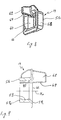
- the elongated latch bolt 24 includes an elongated unitary bolt body 40 having a longitudinal bolt axis X B , as best shown in Figs. 5 and 6 .
- the bolt body 40 of the latch bolt 24 is axially moveable through and relative to the latch casing 22 along the longitudinal casing axis X C between an extended position (shown in Figs. 5 , 6 and 10 ) and a retracted position (shown in Fig. 14 ).
- the bolt body 40 of the latch bolt 24 is axially moveable relative to the latch casing 22 coaxially with the longitudinal casing axis X C , as shown in Figs. 10-12 and 18-19 .
- the bolt body 40 of the latch bolt 24 is pivotable (i.e., rotatable) relative to the casing body 30 of the latch casing 22, as shown in Figs. 13-17 .
- the latch bolt 24 is in the extended position when the lid 4 of the glove box 1 is in the closed position, and in the retracted position when the lid 4 of the glove box 1 is in the open position.
- the latch bolt 24 is in the extended position when the latch assembly 10 is in the latched position, and in the retracted position when the latch assembly 10 is in the unlatched position.
- the bolt body 40 of the latch bolt 24 has a free distal end 41 1 adjacent to and at least partially extending from the front opening 31 1 in the casing body 30, and a proximal end 412 facing the coupler 20 and drivingly coupled to the connecting rod 18.
- the bolt body 40 extends along the longitudinal bolt axis X B between the free distal end 41 1 and the proximal end 41 2 .
- the free distal end 41 1 of the bolt body 40 of latch bolt 24 has a flat, beveled contact surface 42, and a contact rib 44 complementary to the central slot 36 in the latch casing 22 for permitting axial movement of the latch bolt 24 with respect to the latch casing 22 along the longitudinal casing axis X C of the latch casing 22.
- the contact rib 44 of the latch bolt 24 extends into the central slot 36 of the latch casing 22 when the latch bolt 24 pivots relative to the casing body 30 of the latch casing 22.
- the contact rib 44 is formed centrally with respect to a transverse axis perpendicular to the longitudinal bolt axis X B of the bolt body 40.
- the casing body 30 of the latch casing 22 further includes at least one pair of longitudinal ribs 53 formed adjacent to the front opening 31 1 in the casing body 30, and a pair of transversely opposite (in the direction perpendicular to the longitudinal casing axis X C ) semi-cylindrical bolt supports 37 formed adjacent to the rear opening 312 in the casing body 30.
- the longitudinal ribs 53 continuously engage the bolt body 40 so as to allow the linear displacement of the bolt body 40 relative to the casing body 30, while the bolt supports 37 continuously engage the bolt body 40 so as to support the bolt body 40 and allow the linear and pivotal displacement of the bolt body 40 relative to the casing body 30.
- the contact rib 44 of the bolt body 40 has a flat, beveled contact surface 45 1 and a flat strike surface 45 2 configured to selectively engage the striker 14.
- the beveled contact surface 45 1 of the contact rib 44 of the bolt body 40 is coplanar with the contact surface 42 of the bolt body 40 of latch bolt 24.
- the strike surface 45 2 of the bolt body 40 is parallel to the longitudinal bolt axis X B .
- the elongated bolt body 40 of the latch bolt 24 further includes at least one, preferably two beveled outer retain surfaces 46 separated by the contact rib 44 and configured to selectively engage the beveled inner retain surface 35 2 of the beveled control flange 34. As best shown in Figs.
- the at least one beveled outer retain surface 46 is disposed between the free distal end 41 1 and the proximal end 41 2 of the bolt body 40 of the elongated latch bolt 24.
- the beveled outer retain surfaces 46 of the elongated bolt body 40 are configured to cooperate with the beveled inner retain surface 35 2 of the beveled control flange 34 of the casing body 30.
- the elongated bolt body 40 of the latch bolt 24 also includes at least one, preferably two outer guide surfaces 47 separated by the contact rib 44 and configured to selectively engage the inner guide surface 35 3 of the beveled control flange 34.
- the one or more guide surfaces 47 of the elongated bolt body 40 are juxtaposed (or adjacent) to the strike surface 45 2 of the bolt body 40 and to the one or more beveled outer retain surfaces 46 of the elongated bolt body 40.
- the bolt body 40 of the latch bolt 24 is provided with a coupling ball member 48 drivingly connected to one of the distal ends of the connecting rod 18 such that the axial movement of the latch bolt 24 of the latch modules 12 is transmitted to the connecting rod 18, and vice versa.
- the outward end of the connecting rod 18 is provided with a ball socket 19 (best shown in Fig. 2 ) configured to receive the coupling ball member 48 of the bolt body 40 so as to form a ball-and-socket connection 49 for pivotally coupling the latch bolt 24 to the connecting rod 18, as shown in Fig. 1 .
- the spring member 26 is in the form of a torsion spring.
- a torsion spring is known in the art as a spring that works by torsion or twisting, such that when the torsion spring is twisted, it exerts a torque in the opposite direction, proportional to the amount (angle) it is twisted.
- the torsion spring 26 includes a spring coil 50, and two radially projecting spring ends: a bolt spring end 51 engaging the latch bolt 24, and a casing spring end 52 engaging the latch casing 22.
- the casing body 30 further includes a spring end positioning slot 38 configured to securely receive therein the casing spring end 52 of the torsion spring 26.
- the bolt body 40 includes a spring end positioning slot 39 configured to securely receive therein the bolt spring end 51 of the torsion spring 26.
- the torsion spring 26 biases the latch bolt 24 in the direction from the rear opening 31 2 to the front opening 31 1 of the latch casing 22. In other words, the torsion spring 26 biases the free distal end 41 1 of the bolt body 40 away from the latch casing 22. Furthermore, the torsion spring 26 biases the bolt body 40 upwardly toward the beveled control flange 34 of the latch casing 22, as illustrated in Figs. 13-17 .
- the latch bolt 24 further includes a damping buffer 28 mounted to the proximal end 41 2 of the bolt body 40 of the latch bolt 24 for limiting axial movement of the latch bolt 24 relative to the latch casing 22 in the direction from the rear opening 31 2 to the front opening 31 1 of the latch casing 22, as best shown in Fig. 5 .
- the damping buffer 28 is in the form of an O-ring made of an elastomeric material.
- the O-ring 28 is configured to engage the casing body 30 of the latch casing 22 at the rear opening 31 2 thereof when the latch bolt 24 axially moves in the direction from the rear opening 31 2 to the front opening 31 1 of the latch casing 22, thus limiting axial movement of the latch bolt 24 relative to the latch casing 22.
- the damping buffer 28 engages the casing body 30 of the latch casing 22 at the rear opening 31 2 thereof.
- the striker 14 includes a hollow, unitary striker body 56 having a longitudinal striker axis X A , as best shown in Figs. 8 and 9 .
- the hollow striker body 56 includes a continuous wall 58 having a front end 59 1 and a rear end 59 2 , and a strike member 62.
- the strike member 62 axially extends from the front end 59 1 of the continuous wall 58 of the striker body 56 toward the latch module 12.
- the continuous wall 58 of the striker body 56 forms a latch pocket 60 configured for receiving the free distal end 41 1 of the latch bolt 24 therewithin through a latch bolt opening 61 formed at the front end 59 1 of the continuous wall 58 of the striker body 56.
- the striker body 56 has two opposite openings, as illustrated in Figs. 8 and 9 .
- the striker body 56 may have only one opening 61 at the front end 59 1 of the continuous wall 58 of the striker body 56.
- the striker body 56 is mounted to the storage bin 2 of the glove box 1 so that the strike member 62 extends toward (or faces) the cavity 3 in the storage bin 2 and the latch module 12.
- the strike member 62 is in the form of a rib extending parallel to the longitudinal striker axis X A , as best shown in Figs. 8 and 9 . Further according to the exemplary embodiment of the present invention, the strike member 62 is formed centrally with respect to a transverse axis perpendicular to the longitudinal striker axis X A of the striker body 56. The strike member 62 has an actuator surface 64 along and parallel to the longitudinal striker axis X A of the striker body 56.
- FIGs. 10-14 illustrate an opening (or unlatching) sequence of the latch assembly 10 of the glove box 1.
- the lid 4 of the glove box 1 is in the closed position. Accordingly, the latch bolt 24 of each of the first and second latch modules 12 1 and 12 2 is in the extended position, and the damping buffer 28 engages the casing body 30 of the latch casing 22 at the rear opening 31 2 thereof. In this position, the latch bolt 24 of each of the first and second latch modules 12 1 and 12 2 is disposed in the latch pocket 60 of the corresponding first and second striker 14 1 and 14 2 , thus fully engaging the first and second strikers 14 1 and 14 2 , and preventing the lid 4 of the glove box 1 from opening, i.e., from moving to the open position. The latch bolt 24 of each of the first and second latch modules 12 1 and 12 2 is biased in the extended position by the torsion spring 26.
- the actuator assembly 16 displaces both of the first and second connecting rods 18 1 and 18 2 simultaneously in the direction away from the latch casing 22 of each of the corresponding first and second latch modules 12 1 and 12 2 , and toward the coupler 20.
- the first and second connecting rods 18 1 and 18 2 simultaneously move the latch bolt 24 of the corresponding first and second latch modules 12 1 and 12 2 linearly toward the retracted position thereof against the biasing force of the torsion spring 26.
- Synchronization between the first and second latch modules 12 1 and 12 2 is achieved via the coupler 20 and the first and second connecting rods 18 1 and 18 2 .
- the coupler 20 does not require spring loaded elements. It only synchronizes movement of the latching bolts 24 of the first and second latch modules 12 1 and 12 2 .
- Actuation of the first and second latch modules 12 1 and 12 2 is realized by the handle 17 that can be applied to one of the connecting rods 18 or through the coupler 20.
- the actuator assembly 16 may be actuated electrically, without a handle, so that both of the first and second connecting rods 18 1 and 18 2 simultaneously displaced by a solenoid or an electric motor upon pressing an actuator button (not shown).
- the latch bolt 24 of each of the first and second latch modules 12 1 and 12 2 is axially displaced relative to the casing body 30 coaxially with the longitudinal casing axis X C axially away from the corresponding first or second striker 14 1 and 14 2 against the biasing force of the torsion spring 26.
- the latch bolt 24 axially slides relative to the casing body 30 coaxially with the longitudinal casing axis X C by slidingly engaging the outer guide surfaces 47 of the latch bolt 24 with the inner guide surface 35 3 of the casing body 30.
- the damping buffer 28 is axially spaced from the casing body 30 of the latch casing 22.
- the latch bolt 24 is partially disposed in the latch pocket 60 of the striker 14.
- the latch bolt 24 when the inward displacement of the latch bolt 24 is sufficient to effectively disengage the bolt body 40 from the front end 59 1 of the striker 14, the latch bolt 24 fully escapes the latch pocket 60 (i.e., the front end 59 1 of the striker body 56) and permits opening of the lid 4 of the glove box 1, as shown in Fig. 12 .
- the outer guide surfaces 47 of the latch bolt 24 still partially slidingly engage the inner guide surface 35 3 of the casing body 30.
- the pivotal (or rotational) movement of the bolt body 40 is imparted by the biasing force of the torsion spring 26 so that the beveled outer retain surfaces 46 of the bolt body 40 engage the beveled inner retain surface 35 2 of the beveled control flange 34 of the casing body 30.
- the longitudinal bolt axis X B of the bolt body 40 is oblique (i.e., neither perpendicular nor parallel) relative to the longitudinal casing axis X C of the casing body 30.
- the contact rib 44 of the bolt body 40 enters the central slot 36 of the beveled control flange 34 of the casing body 30, so that the consequent axial movement of the bolt body 40 is guided by the central slot 36.
- the torsion spring 26 pushes the bolt body 40 further upward into the cavity 32 of the casing body 30 until the outer guide surfaces 47 of the bolt body 40 engage the inner rest surface 33 of the casing body 30, thus placing the latch bolt 24 in the retracted position.
- the torsion spring 26 pushes the beveled outer retain surfaces 46 of the bolt body 40 firmly axially against the beveled inner retain surface 35 2 of the casing body 30 and holds in the retracted position, thus preventing movement of the free distal end 41 1 of the bolt body 40 out of the casing body 30 of the latch casing 22.
- the longitudinal bolt axis X B of the bolt body 40 is oblique with respect to the longitudinal casing axis X C of the casing body 30, as shown in Fig. 14 .
- the contact rib 44 of the bolt body 40 is disposed in the central slot 36 of the beveled control flange 34 of the casing body 30. Therefore, during the unlatching of the latch assembly 10 of the glove box 1 the latching bolts 24 is pulled into the latch casing 22 and is retained (or held) in the retracted position upon release of the handle 17 of the lid 4. In the retracted position the latching bolts 24 is fully retracted and retained in the latch casing 22 by the biasing force of the torsion spring 26 of the latch module 12.
- the longitudinal bolt axis X B of the latch bolt 24 is coaxial with the longitudinal casing axis X C of the latch casing 22 (as illustrated in Fig. 10 ), while in the retracted position of the latch bolt 24, the longitudinal bolt axis X B of the latch bolt 24 is oblique with respect to the longitudinal casing axis X C of the latch casing 22 (as illustrated in Fig. 14 ).
- Figs. 15-19 illustrate a closing (or latching) sequence of the latch assembly 10 of the glove box 1.
- the lid 4 of the glove box 1 is in the open position.
- the latch bolt 24 of each of the first and second latch modules 12 1 and 12 2 is in the retracted position.
- the lid 4 of the glove box 1 with the latch module 12 is moved by the user toward the closed position, i.e., toward the storage bin 2 and the striker 14.
- the latching bolts 24 is in the retracted position, and the strike surface 45 2 of the contact rib 44 of the bolt body 40 engages the actuator surface 64 of the strike member 62 of the striker 14.
- the strike member 62 of each of the first and second strikers 14 1 and 14 2 pushes the contact rib 44 of the bolt body 40 of each of the first and second latch modules 12 1 and 12 2 downwardly away from the inner rest surface 33 of the casing body 30 of each of the first and second latch modules 12 1 and 12 2 .
- the strike member 62 of the striker 14 imparts pivotal (or rotational) movement to the bolt body 40.
- the bolt body 40 concurrently moves axially away from the casing body 30 of each of the first and second latch modules 12 1 and 12 2 toward the latch pocket 60 of the corresponding one of the first and second striker 14 1 and 14 2 .
- the bolt body 40 is guided by the contact rib 44 of the bolt body 40 sliding in the central slot 36 of the beveled control flange 34 of the casing body 30.
- the free distal end 41 1 of the bolt body 40 of latch bolt 24 further enters the latch pocket 60 of the striker 14 until the damping buffer 28 engages the casing body 30 of the latch casing 22 at the rear opening 31 2 thereof, thus placing the latch bolt 24 in the extended position and preventing the lid 4 from opening.
- the latch assembly 10 is in the latched position, and the lid 4 of the glove box 1 is in the closed position.
- the latch bolt 24 of the latch assembly 10 of the present invention is released to the extended position after the lid 4 of the storage compartment 1 is closed. As a result, the latch assembly 10 decreases closing force to the lid 4, initial impact noise and parts deformation during closing of the lid 4.
- the elongated latch bolt 24 of the present invention is moveable between the extended position, in which the longitudinal bolt axis X B of the latch bolt 24 is coaxial with the longitudinal casing axis X C of the latch casing 22, and the retracted position, in which the longitudinal bolt axis X B of the latch bolt 24 is oblique with respect to the longitudinal casing axis Xc of the latch casing 22.
- the torsion spring 26 biases the latch bolt 24 toward the retracted position
- the torsion spring 26 biases the latch bolt 24 toward the extended position.
- the outer retain surfaces 46 of the latch bolt 24 is disengaged from the inner retain surface 35 2 of the latch casing 22 by the strike member 62 of the striker 14.
- the present invention provides a novel latch assembly for a storage compartment of an automotive vehicle.
- the novel latch assembly comprises a latch bolt that retained (or held) retracted when the storage compartment is open and is released to an extended (latched) position after a lid of the storage compartment is closed. This is enabled by a shape of a latch bolt/latch casing interface combined with a spring member and a striker fixed to the storage bin or, alternatively, to the lid of the storage compartment.
Landscapes
- Engineering & Computer Science (AREA)
- Mechanical Engineering (AREA)
- Structural Engineering (AREA)
- Vehicle Step Arrangements And Article Storage (AREA)
- Lock And Its Accessories (AREA)
Abstract
Description
- The present invention generally relates to latch systems for storage compartments in automobiles. More particularly, the invention relates to an extended latch bolt assembly for use with a storage compartment of an automobile.
- Automotive vehicles (or automobiles) are commonly equipped with various storage (or small article) compartments for stowing vehicle accessories, personal belongings and other objects. Normally, storage compartments for accommodating small articles are provided in a passenger compartment or cabin of automobiles.
- For example, vehicles typically include a glove box usually located in the dash on the front passenger side of the passenger compartment, armrest storage compartments, closed driver storage compartments, etc. The glove box has a housing typically installed with the dash and has walls that generally define a compartment with an open front side. A pivoting lid or door is pivotally connected to the housing such that the lid pivots between an open position in which the compartment is accessible and a closed position in which access is prevented. The lid typically has a latch assembly for latching the door closed and is actuatable by a user to release the door and allow it to open. A conventional latch may include a pull lever that releases a latch and enables a user to pull the door open.
- Currently used latch assemblies have issues with increased closing force, initial impact noise and parts deformation during closing. It is caused by latching bolts remaining extended when in an open hatch condition. During closing of a lid of a storage compartment, the latch bolts hit fixed parts of a storage bin and have to be pushed into a recess before latching can occur.
- Thus, while latch assemblies for storage compartments of an automobile, including but not limited to that discussed above, have proven to be acceptable for vehicular applications and conditions, improvements that may enhance and quiet their performance are possible.
- According to the invention, there is provided a latch assembly for a storage compartment in an automotive vehicle. The latch assembly is adapted to selectively secure a lid to a storage bin of the storage compartment. The latch assembly has a latched position and an unlatched position. When latched, a latch bolt extends from within a latch casing and engages an opposed anchor pocket/striker so as to secure the lid. When unlatched, the latch bolt is withdrawn into, and retained within, the latch casing until such time as the lid is again closed, and by action of the latch bolt against the anchor pocket/striker, the latch bolt is released and extends via a bias spring into the anchor pocket/striker and retains the lid in a closed position.
- The latch assembly includes a first latch module, which comprises a hollow latch casing, an elongated latch bolt extending through the cavity in the hollow latch casing, and a spring member disposed within the cavity in the hollow latch casing. The hollow latch casing forms a cavity and has an inner retaining surface within the cavity, a front opening and a rear opening coaxial with the front opening along a longitudinal casing axis of the hollow latch casing. The spring member has a bolt spring end engaging the elongated latch bolt and a casing spring end engaging the hollow latch casing. The elongated latch bolt has a free distal end and a proximal end disposed along a longitudinal bolt axis of the elongated latch bolt, and an outer retaining surface configured to cooperate with the inner retaining surface of the hollow latch casing and disposed between the free distal end and the proximal end of the elongated latch bolt. The elongated bolt body is moveable axially and pivotally relative to the latch casing. The elongated latch bolt is moveable between an extended position, in which the longitudinal bolt axis of the latch bolt is coaxial with the longitudinal casing axis of the latch casing, and a retracted position, in which the longitudinal bolt axis of the latch bolt is oblique with respect to the longitudinal casing axis of the latch casing. The spring member biases the free distal end of the elongated latch bolt axially away from the latch casing and biases the outer retaining surface of the elongated latch bolt pivotally toward the inner retaining surface of the latch casing so that the elongated latch bolt retained both in the extended position and the retracted position by the spring member. The outer retain surface of the elongated latch bolt engages the inner retaining surface of the latch casing in the retracted position of the elongated latch bolt. The outer retaining surface of the elongated latch bolt is disengaged from the inner retaining surface of the latch casing in the extended position of the elongated latch bolt. The spring member biases and retains the elongated latch bolt toward the retracted position when the outer retaining surface of the latch bolt is engaged with the inner retaining surface of the latch casing. The spring member biases the elongated latch bolt toward the extended position when the outer retaining surface of the elongated latch bolt is disengaged from the inner retaining surface of the latch casing.
- Other aspects of the invention will become more apparent upon reading the following detailed description of the exemplary embodiments.
- The accompanying drawings are incorporated in and constitute a part of the specification. The drawings, together with the general description given above and the detailed description of the exemplary embodiments and methods given below, serve to explain the principles of the invention. In these drawings:
-
Fig. 1 is a perspective view of a glove box according to an exemplary embodiment of the present invention; -
FIG. 2 is an exploded perspective view of a latch assembly according to the exemplary embodiment of the present invention; -
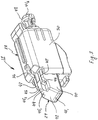
Fig. 3 is a perspective view of a latch module according to the exemplary embodiment of the present invention; -
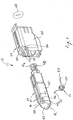
FIG. 4 is an exploded perspective view of the latch module ofFig. 3 ; -
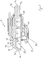
FIG. 5 is a sectional view of the latch module ofFig. 3 ; -
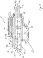
FIG. 6 is a sectional view of the latch module ofFig. 3 without a spring member; -
FIG. 7 is a sectional view of a latch casing of the latch module ofFig. 3 ; -
Fig. 8 is a perspective view of a striker according to the exemplary embodiment of the present invention; -
FIG. 9 is sectional view of the striker ofFig. 8 ; -
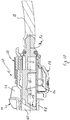
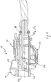
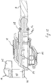
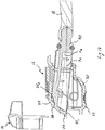
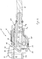
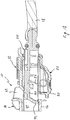
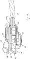
FIGS. 10-14 illustrate an unlatching sequence of the latch assembly according to the exemplary embodiment of the present invention; and -
FIGS. 15-19 illustrate a latching sequence of the latch assembly according to the exemplary embodiment of the present invention. - Reference will now be made in detail to an exemplary embodiment and methods of the invention as illustrated in the accompanying drawings, in which like reference characters designate like or corresponding parts throughout the drawings. It should be noted, however, that the invention in its broader aspects is not limited to the specific details, representative devices and methods, and illustrative examples shown and described in connection with the exemplary embodiments and methods.
- This description of exemplary embodiments is intended to be read in connection with the accompanying drawings, which are to be considered part of the entire written description. In the description, relative terms such as "horizontal," "vertical," "front," "rear," "left," "right," "upper," "lower," "top," and "bottom" as well as derivatives thereof (e.g., "horizontally," "downwardly," "upwardly," etc.) should be construed to refer to the orientation as then described or as shown in the drawing figure under discussion and to the orientation relative to a vehicle body. These relative terms are for convenience of description and normally are not intended to require a particular orientation. Terms concerning attachments, coupling and the like, such as "connected" and "interconnected", refer to a relationship wherein structures are secured or attached to one another either directly or indirectly through intervening structures, as well as both movable or rigid attachments or relationships, unless expressly described otherwise. The term "operatively connected" is such an attachment, coupling or connection that allows the pertinent structures to operate as intended by virtue of that relationship. The term "integral" (or "unitary") relates to a part made as a single part, or a part made of separate components fixedly (i.e., non-moveably) connected together. Additionally, the words "a" and/or "an" as used in the claims mean "at least one" and the word "two" as used in the claims means "at least two". For the purpose of clarity, some technical material that is known in the related art has not been described in detail in order to avoid unnecessarily obscuring the disclosure.
- The present invention relates to a latch assembly for storage compartment of an automobile (or automotive vehicle), provided to accommodate small articles and/or used for miscellaneous storage. An exemplary embodiment of the automotive storage compartment is generally represented in
Fig. 1 of the accompanying drawings by reference numeral 1. In the exemplary embodiment of the present invention, the storage compartment of the automobile is in the form of a glove box (or glove compartment) 1 of an automobile (or automotive vehicle), provided to accommodate small articles. It will be appreciated that any other storage compartment in the automotive vehicle that includes an opening/closing member (i.e., closable lid) is within the scope of the present invention. - Typically, the glove box 1 is built into a dashboard (or instrument panel) (not shown) of an automobile, and is located over a front-seat passenger's footwell. The glove box 1 is conventionally used for miscellaneous storage. The glove box 1 comprises a hollow storage bin 2 (also known as a storage box or cassette), which is disposed inside the instrument panel, a
lid 4 pivotally mounted to thestorage bin 2, and alatch assembly 10 configured to for selectively secure thelid 4 to thestorage bin 2. Thestorage bin 2, thelid 4, and thelatch assembly 10 collectively define the glove box 1 of an automobile. Thestorage bin 2 is hollow so as to define astorage cavity 3 therein. Thelid 4 is moveably (e.g., pivotally) attached to thestorage bin 2 so as to move between an open position (shown inFig. 1 ) allowing access to thestorage cavity 3, and a closed position preventing access to thestorage cavity 3. In other words, thelid 4 of the glove box 1 is configured to open and close anopening 6 to thestorage cavity 3 in thestorage bin 2 of the glove box 1. Typically, thelid 4 is rotatably (e.g., pivotally) coupled to thestorage bin 2 of the glove box 1 via a hinge. - The
lid 4 includes an outer panel 5t and an inner panel 5i. The outer panel 5t of thelid 4 forms a part of an outer surface of the instrument panel. Thelatch assembly 10 is mounted between the inner panel 5i and the outer panel 5t of thelid 4 as will be discussed in detail below. Also, thelatch assembly 10 has a latched position (Figs. 10 and19 ), wherein respective parts of thelatch assembly 10 removably engage thestorage bin 2, and an unlatched position (Figs. 13 and14 ), wherein those parts of thelatch assembly 10 are disengaged from thestorage bin 2, such that thelid 4 is released from thestorage bin 2 of the glove box 1. - The
latch assembly 10 comprises at least onelatch module 121 mounted to thelid 4, at least one striker (or anchor pocket) 141 associated with the at least onelatch module 121 and mounted to thestorage bin 2, anactuator assembly 16 for selectively moving thelatch assembly 10 between the latched and unlatched positions, and at least one connectingrod 181 operatively connecting theactuator assembly 16 to the at least onelatch module 121. According to the exemplary embodiment of the present invention, theactuator assembly 16 is mounted to the outer panel 5t of thelid 4. - Alternatively, the above described structure of the
latch assembly 10 may be inverted. In other words, the at least onelatch module 121 and theactuator assembly 16 may be mounted to thestorage bin 2, while the at least one striker (or anchor pocket) 141 mounted to thepivotable lid 4. - The
actuator assembly 16, according to the exemplary embodiment of the present invention, includes ahandle 17 configured to being pulled (or, alternatively, pushed or rotated). Alternatively, theactuator assembly 16 may be actuated electrically, without a handle. - According to the exemplary embodiment of the present invention, the
latch assembly 10 comprises two functionally identical latch modules: afirst latch module 121 and a second (or additional)latch module 122 securely mounted to opposite (e.g. left and right) sides of thelid 4, and two functionally identical strikers (or anchor pockets): afirst striker 141 and asecond striker 142 fixed (i.e., non-moveably attached) to opposite (e.g. left and right) sides of thestorage bin 2 of the glove box 1. In other words, thefirst striker 141 and thesecond striker 142 are integrated into thestorage bin 2 of the glove box 1. Alternatively, thefirst striker 141 and thesecond striker 142 may be formed with thestorage bin 2 as a single-piece part. According to the exemplary embodiment of the present invention, each of the first andsecond latch modules lid 4 between the outer panel 5t and the inner panel 5i of thelid 4. Also, thelatch assembly 10 comprises two connecting rods: a first connectingrod 181 and a second connectingrod 182. - The
first striker 141 is associated with thefirst latch module 121, and thesecond striker 142 is associated with thesecond latch module 122. Thus, the exemplary embodiment of thelatch assembly 10 comprises the first andsecond latch modules second strikers actuator assembly 16 for selectively moving thelatch assembly 10 between the latched and unlatched positions, the second connectingrod 182 operatively connecting theactuator assembly 16 to thefirst latch module 121, a second connectingrod 182 operatively connected to thesecond latch modules 122, and acoupler 20 operatively connecting the first connectingrod 181 to the second connectingrod 182, as best shown inFig. 1 . In other words, the first connectingrod 181 operatively couples thefirst latch module 121 to thecoupler 20, while the second connectingrod 182 operatively couples thesecond latch module 122 to thecoupler 20. - The first and
second latch modules reference numeral 12 without a subscript numeral when generically referring to each of the first andsecond latch modules second strikers reference numeral 14 without a subscript numeral when generically referring to each of the first andsecond strikers rods reference numeral 18 without a subscript numeral when generically referring to each of the first and second connectingrods - As illustrated in
Fig. 1 , an outward (or distal) end of each of the first and second connectingrods latch modules 12, while an inward (or proximal) end of each of the first and second connectingrods coupler 20 configured to provide a complementary reciprocating displacement of the first and second connectingrods actuator assembly 16 by a user, the displacement of the first connectingrod 181 is transmitted to the second connectingrod 182 by thecoupler 20 so that the second connectingrod 182 is also displaced. Specifically, in response to actuation of theactuator assembly 16 by the user, the first connectingrod 181 is retracted into thecoupler 20, which, in turn, retracts the second connectingrod 182 into thecoupler 20. For example, thecoupler 20 may include a gear mechanism rotation of which may pull both the first and second connectingrods housing 21 of thecoupler 20. A variety of couplers may be used with the present invention, such as disclosed inU.S. Patent Application Publication Nos. 2014/0152026 and2018/0230720 , which are incorporated herein by reference in their entirety. - Each of the first and
second latch modules 12 includes alatch casing 22, anelongated latch bolt 24 extending through thelatch casing 22, and aspring member 26. Thelatch casing 22 is fixed (i.e., non-moveably attached) to thelid 4. Thelatch casing 22 includes a hollow,unitary casing body 30 having a longitudinal casing axis XC, as best shown inFigs. 4-7 . Thehollow casing body 30 forms acavity 32, which receives thelatch bolt 24 therewithin. Thecasing body 30 of thelatch casing 22 has a front (or first)opening 311, and a rear (or second) opening 312 coaxial with thefront opening 311 along the longitudinal casing axis XC, such that thelatch bolt 24 partially extends from the front andrear openings casing body 30. - The
casing body 30 of thelatch casing 22 further includes abeveled control flange 34 at thefront opening 311 of thecasing body 30. Thebeveled control flange 34 obliquely extends radially inwardly toward the longitudinal casing axis Xc and partially forms thefront opening 311 in thecasing body 30. Thebeveled control flange 34 has a beveled outer surface 351, a beveled inner retain surface 352, and an inner guide surface 353 parallel to the longitudinal casing axis XC. The beveled inner retain surface 352 of thebeveled control flange 34 obliquely extends radially inwardly toward the longitudinal casing axis XC and is juxtaposed to aninner rest surface 33 of thecasing body 30 partially forming thecavity 32 in thecasing body 30. Thebeveled control flange 34 of thecasing body 30 has a central slot (or gap, or opening) 36. According to the exemplary embodiment of the present invention, thecentral slot 36 is formed centrally with respect to a transverse axis perpendicular to the longitudinal casing axis Xc of thelatch casing 22. - The
elongated latch bolt 24 includes an elongatedunitary bolt body 40 having a longitudinal bolt axis XB, as best shown inFigs. 5 and6 . Thebolt body 40 of thelatch bolt 24 is axially moveable through and relative to thelatch casing 22 along the longitudinal casing axis XC between an extended position (shown inFigs. 5 ,6 and10 ) and a retracted position (shown inFig. 14 ). Moreover, thebolt body 40 of thelatch bolt 24 is axially moveable relative to thelatch casing 22 coaxially with the longitudinal casing axis XC, as shown inFigs. 10-12 and18-19 . Additionally, thebolt body 40 of thelatch bolt 24 is pivotable (i.e., rotatable) relative to thecasing body 30 of thelatch casing 22, as shown inFigs. 13-17 . Thelatch bolt 24 is in the extended position when thelid 4 of the glove box 1 is in the closed position, and in the retracted position when thelid 4 of the glove box 1 is in the open position. In other words, thelatch bolt 24 is in the extended position when thelatch assembly 10 is in the latched position, and in the retracted position when thelatch assembly 10 is in the unlatched position. - The
bolt body 40 of thelatch bolt 24 has a freedistal end 411 adjacent to and at least partially extending from thefront opening 311 in thecasing body 30, and aproximal end 412 facing thecoupler 20 and drivingly coupled to the connectingrod 18. In other words, thebolt body 40 extends along the longitudinal bolt axis XB between the freedistal end 411 and theproximal end 412. The freedistal end 411 of thebolt body 40 oflatch bolt 24 has a flat,beveled contact surface 42, and acontact rib 44 complementary to thecentral slot 36 in thelatch casing 22 for permitting axial movement of thelatch bolt 24 with respect to thelatch casing 22 along the longitudinal casing axis XC of thelatch casing 22. Specifically, thecontact rib 44 of thelatch bolt 24 extends into thecentral slot 36 of thelatch casing 22 when thelatch bolt 24 pivots relative to thecasing body 30 of thelatch casing 22. According to the exemplary embodiment of the present invention, thecontact rib 44 is formed centrally with respect to a transverse axis perpendicular to the longitudinal bolt axis XB of thebolt body 40. - The
casing body 30 of thelatch casing 22 further includes at least one pair oflongitudinal ribs 53 formed adjacent to thefront opening 311 in thecasing body 30, and a pair of transversely opposite (in the direction perpendicular to the longitudinal casing axis XC) semi-cylindrical bolt supports 37 formed adjacent to the rear opening 312 in thecasing body 30. Thelongitudinal ribs 53 continuously engage thebolt body 40 so as to allow the linear displacement of thebolt body 40 relative to thecasing body 30, while the bolt supports 37 continuously engage thebolt body 40 so as to support thebolt body 40 and allow the linear and pivotal displacement of thebolt body 40 relative to thecasing body 30. - The
contact rib 44 of thebolt body 40 has a flat,beveled contact surface 451 and aflat strike surface 452 configured to selectively engage thestriker 14. Thebeveled contact surface 451 of thecontact rib 44 of thebolt body 40 is coplanar with thecontact surface 42 of thebolt body 40 oflatch bolt 24. Moreover, according to the exemplary embodiment of the present invention, thestrike surface 452 of thebolt body 40 is parallel to the longitudinal bolt axis XB. Theelongated bolt body 40 of thelatch bolt 24 further includes at least one, preferably two beveled outer retain surfaces 46 separated by thecontact rib 44 and configured to selectively engage the beveled inner retain surface 352 of thebeveled control flange 34. As best shown inFigs. 3-6 , the at least one beveledouter retain surface 46 is disposed between the freedistal end 411 and theproximal end 412 of thebolt body 40 of theelongated latch bolt 24. The beveled outer retain surfaces 46 of theelongated bolt body 40 are configured to cooperate with the beveled inner retain surface 352 of thebeveled control flange 34 of thecasing body 30. Moreover, theelongated bolt body 40 of thelatch bolt 24 also includes at least one, preferably two outer guide surfaces 47 separated by thecontact rib 44 and configured to selectively engage the inner guide surface 353 of thebeveled control flange 34. In other words, the one or more guide surfaces 47 of theelongated bolt body 40 are juxtaposed (or adjacent) to thestrike surface 452 of thebolt body 40 and to the one or more beveled outer retain surfaces 46 of theelongated bolt body 40. - Furthermore, the
bolt body 40 of thelatch bolt 24 is provided with acoupling ball member 48 drivingly connected to one of the distal ends of the connectingrod 18 such that the axial movement of thelatch bolt 24 of thelatch modules 12 is transmitted to the connectingrod 18, and vice versa. Specifically, according to the exemplary embodiment of the present invention, the outward end of the connectingrod 18 is provided with a ball socket 19 (best shown inFig. 2 ) configured to receive thecoupling ball member 48 of thebolt body 40 so as to form a ball-and-socket connection 49 for pivotally coupling thelatch bolt 24 to the connectingrod 18, as shown inFig. 1 . - According to the exemplary embodiment of the present invention, the
spring member 26 is in the form of a torsion spring. A torsion spring is known in the art as a spring that works by torsion or twisting, such that when the torsion spring is twisted, it exerts a torque in the opposite direction, proportional to the amount (angle) it is twisted. Thetorsion spring 26 includes aspring coil 50, and two radially projecting spring ends: abolt spring end 51 engaging thelatch bolt 24, and acasing spring end 52 engaging thelatch casing 22. Thecasing body 30 further includes a springend positioning slot 38 configured to securely receive therein thecasing spring end 52 of thetorsion spring 26. Similarly, thebolt body 40 includes a spring end positioning slot 39 configured to securely receive therein thebolt spring end 51 of thetorsion spring 26. - Moreover, as illustrated in
Fig. 5 , thetorsion spring 26 biases thelatch bolt 24 in the direction from therear opening 312 to thefront opening 311 of thelatch casing 22. In other words, thetorsion spring 26 biases the freedistal end 411 of thebolt body 40 away from thelatch casing 22. Furthermore, thetorsion spring 26 biases thebolt body 40 upwardly toward thebeveled control flange 34 of thelatch casing 22, as illustrated inFigs. 13-17 . - The
latch bolt 24 further includes a dampingbuffer 28 mounted to theproximal end 412 of thebolt body 40 of thelatch bolt 24 for limiting axial movement of thelatch bolt 24 relative to thelatch casing 22 in the direction from therear opening 312 to thefront opening 311 of thelatch casing 22, as best shown inFig. 5 . According to the exemplary embodiment of the present invention, the dampingbuffer 28 is in the form of an O-ring made of an elastomeric material. The O-ring 28 is configured to engage thecasing body 30 of thelatch casing 22 at therear opening 312 thereof when thelatch bolt 24 axially moves in the direction from therear opening 312 to thefront opening 311 of thelatch casing 22, thus limiting axial movement of thelatch bolt 24 relative to thelatch casing 22. In other words, in the extended position of thelatch bolt 24, the dampingbuffer 28 engages thecasing body 30 of thelatch casing 22 at therear opening 312 thereof. - The
striker 14 includes a hollow,unitary striker body 56 having a longitudinal striker axis XA, as best shown inFigs. 8 and 9 . Thehollow striker body 56 includes acontinuous wall 58 having afront end 591 and arear end 592, and astrike member 62. Thestrike member 62 axially extends from thefront end 591 of thecontinuous wall 58 of thestriker body 56 toward thelatch module 12. Thecontinuous wall 58 of thestriker body 56 forms alatch pocket 60 configured for receiving the freedistal end 411 of thelatch bolt 24 therewithin through alatch bolt opening 61 formed at thefront end 591 of thecontinuous wall 58 of thestriker body 56. According to the exemplary embodiment of the present invention, thestriker body 56 has two opposite openings, as illustrated inFigs. 8 and 9 . Alternatively, thestriker body 56 may have only oneopening 61 at thefront end 591 of thecontinuous wall 58 of thestriker body 56. Thestriker body 56 is mounted to thestorage bin 2 of the glove box 1 so that thestrike member 62 extends toward (or faces) thecavity 3 in thestorage bin 2 and thelatch module 12. - According to the exemplary embodiment of the present invention, the
strike member 62 is in the form of a rib extending parallel to the longitudinal striker axis XA, as best shown inFigs. 8 and 9 . Further according to the exemplary embodiment of the present invention, thestrike member 62 is formed centrally with respect to a transverse axis perpendicular to the longitudinal striker axis XA of thestriker body 56. Thestrike member 62 has anactuator surface 64 along and parallel to the longitudinal striker axis XA of thestriker body 56. - Operation of the
latch assembly 10 according to the exemplary embodiment of the present invention is described hereafter.Figs. 10-14 illustrate an opening (or unlatching) sequence of thelatch assembly 10 of the glove box 1. - Referring first to
Fig. 10 , thelid 4 of the glove box 1 is in the closed position. Accordingly, thelatch bolt 24 of each of the first andsecond latch modules buffer 28 engages thecasing body 30 of thelatch casing 22 at therear opening 312 thereof. In this position, thelatch bolt 24 of each of the first andsecond latch modules latch pocket 60 of the corresponding first andsecond striker second strikers lid 4 of the glove box 1 from opening, i.e., from moving to the open position. Thelatch bolt 24 of each of the first andsecond latch modules torsion spring 26. - In operation, upon actuation of the
actuator assembly 16, i.e., when thehandle 17 is pulled away from thelid 4 of the glove box 1 in the closed position, theactuator assembly 16 displaces both of the first and second connectingrods second latch modules coupler 20. As a result, the first and second connectingrods latch bolt 24 of the corresponding first andsecond latch modules torsion spring 26. Synchronization between the first andsecond latch modules coupler 20 and the first and second connectingrods coupler 20 does not require spring loaded elements. It only synchronizes movement of the latchingbolts 24 of the first andsecond latch modules second latch modules handle 17 that can be applied to one of the connectingrods 18 or through thecoupler 20. - As noted above, alternatively, the
actuator assembly 16 may be actuated electrically, without a handle, so that both of the first and second connectingrods - Initially, as illustrated in
Fig. 11 , thelatch bolt 24 of each of the first andsecond latch modules casing body 30 coaxially with the longitudinal casing axis XC axially away from the corresponding first orsecond striker torsion spring 26. Thelatch bolt 24 axially slides relative to thecasing body 30 coaxially with the longitudinal casing axis XC by slidingly engaging the outer guide surfaces 47 of thelatch bolt 24 with the inner guide surface 353 of thecasing body 30. The dampingbuffer 28 is axially spaced from thecasing body 30 of thelatch casing 22. Thelatch bolt 24 is partially disposed in thelatch pocket 60 of thestriker 14. - As illustrated in
Fig. 12 , upon further pulling of thehandle 17, and, as a result, further displacement of thelatch bolt 24 of each of the first andsecond latch modules casing body 30 coaxially with the longitudinal casing axis XC and axially away from the corresponding first orsecond striker torsion spring 26, thelatch bolt 24 is disengaged from thestriker 14. In other words, thelatch bolt 24 is out of thelatch pocket 60 of thestriker body 56 of thestriker 14, thus allowing thelid 4 to pivot toward the open position. Thus, when the inward displacement of thelatch bolt 24 is sufficient to effectively disengage thebolt body 40 from thefront end 591 of thestriker 14, thelatch bolt 24 fully escapes the latch pocket 60 (i.e., thefront end 591 of the striker body 56) and permits opening of thelid 4 of the glove box 1, as shown inFig. 12 . The outer guide surfaces 47 of thelatch bolt 24 still partially slidingly engage the inner guide surface 353 of thecasing body 30. - As illustrated in
Fig. 13 , upon further displacement of thelatch bolt 24 of each of the first andsecond latch modules casing body 30 coaxially with the longitudinal casing axis XC, thebolt body 40 retracts into thecavity 32 of thecasing body 30 so that the outer guide surfaces 47 of thelatch bolt 24 is disengaged from the inner guide surface 353 of thecasing body 30. Consequently, thebolt body 40 pivots upward over the bolt supports 37 of thecasing body 30. The pivotal (or rotational) movement of thebolt body 40 is imparted by the biasing force of thetorsion spring 26 so that the beveled outer retain surfaces 46 of thebolt body 40 engage the beveled inner retain surface 352 of thebeveled control flange 34 of thecasing body 30. In this position the longitudinal bolt axis XB of thebolt body 40 is oblique (i.e., neither perpendicular nor parallel) relative to the longitudinal casing axis XC of thecasing body 30. Also, thecontact rib 44 of thebolt body 40 enters thecentral slot 36 of thebeveled control flange 34 of thecasing body 30, so that the consequent axial movement of thebolt body 40 is guided by thecentral slot 36. - As illustrated in
Fig. 14 , upon further displacement of thelatch bolt 24 of each of the first andsecond latch modules casing body 30, thetorsion spring 26 pushes thebolt body 40 further upward into thecavity 32 of thecasing body 30 until the outer guide surfaces 47 of thebolt body 40 engage theinner rest surface 33 of thecasing body 30, thus placing thelatch bolt 24 in the retracted position. In this position thetorsion spring 26 pushes the beveled outer retain surfaces 46 of thebolt body 40 firmly axially against the beveled inner retain surface 352 of thecasing body 30 and holds in the retracted position, thus preventing movement of the freedistal end 411 of thebolt body 40 out of thecasing body 30 of thelatch casing 22. Moreover, the longitudinal bolt axis XB of thebolt body 40 is oblique with respect to the longitudinal casing axis XC of thecasing body 30, as shown inFig. 14 . Also, thecontact rib 44 of thebolt body 40 is disposed in thecentral slot 36 of thebeveled control flange 34 of thecasing body 30. Therefore, during the unlatching of thelatch assembly 10 of the glove box 1 the latchingbolts 24 is pulled into thelatch casing 22 and is retained (or held) in the retracted position upon release of thehandle 17 of thelid 4. In the retracted position the latchingbolts 24 is fully retracted and retained in thelatch casing 22 by the biasing force of thetorsion spring 26 of thelatch module 12. Moreover, in the extended position of thelatch bolt 24, the longitudinal bolt axis XB of thelatch bolt 24 is coaxial with the longitudinal casing axis XC of the latch casing 22 (as illustrated inFig. 10 ), while in the retracted position of thelatch bolt 24, the longitudinal bolt axis XB of thelatch bolt 24 is oblique with respect to the longitudinal casing axis XC of the latch casing 22 (as illustrated inFig. 14 ). -
Figs. 15-19 illustrate a closing (or latching) sequence of thelatch assembly 10 of the glove box 1. Referring first toFig. 14 , thelid 4 of the glove box 1 is in the open position. Accordingly, thelatch bolt 24 of each of the first andsecond latch modules lid 4 of the glove box 1 with thelatch module 12 is moved by the user toward the closed position, i.e., toward thestorage bin 2 and thestriker 14. In the position illustrated inFig. 15 , the latchingbolts 24 is in the retracted position, and thestrike surface 452 of thecontact rib 44 of thebolt body 40 engages theactuator surface 64 of thestrike member 62 of thestriker 14. - As illustrated in
Fig. 16 , upon further displacement of thelid 4 relative to thestorage bin 2, thestrike member 62 of each of the first andsecond strikers contact rib 44 of thebolt body 40 of each of the first andsecond latch modules inner rest surface 33 of thecasing body 30 of each of the first andsecond latch modules strike member 62 of thestriker 14 imparts pivotal (or rotational) movement to thebolt body 40. At the same time, due to the biasing force of thetorsion spring 26, thebolt body 40 concurrently moves axially away from thecasing body 30 of each of the first andsecond latch modules latch pocket 60 of the corresponding one of the first andsecond striker bolt body 40 away from theinner rest surface 33 of thecasing body 30, thebolt body 40 is guided by thecontact rib 44 of thebolt body 40 sliding in thecentral slot 36 of thebeveled control flange 34 of thecasing body 30. - As illustrated in
Fig. 17 , upon further pivotal displacement of thelatch bolt 24 of each of the first andsecond latch modules inner rest surface 33 of thecasing body 30 against the biasing force of thetorsion spring 26, the beveled outer retain surfaces 46 of thebolt body 40 are disengaged from the beveled inner retain surface 352 of thebeveled control flange 34 of thecasing body 30. In other words, thelatch bolt 24 of each of the first andsecond latch modules latch pocket 60 of the corresponding first andsecond strikers torsion spring 26. - Upon further linear displacement of the
latch bolt 24 toward thestriker 14 due to the biasing force of thetorsion spring 26, the freedistal end 411 of thebolt body 40 oflatch bolt 24 enters thelatch pocket 60 of thestriker 14, as illustrated inFig. 18 . In other words, thelatch bolt 24 is released to the extended position after thelid 4 of the storage compartment 1 is closed. - Finally, as illustrated in
Fig. 19 , the freedistal end 411 of thebolt body 40 oflatch bolt 24 further enters thelatch pocket 60 of thestriker 14 until the dampingbuffer 28 engages thecasing body 30 of thelatch casing 22 at therear opening 312 thereof, thus placing thelatch bolt 24 in the extended position and preventing thelid 4 from opening. Subsequently, thelatch assembly 10 is in the latched position, and thelid 4 of the glove box 1 is in the closed position. Moreover, thelatch bolt 24 of thelatch assembly 10 of the present invention is released to the extended position after thelid 4 of the storage compartment 1 is closed. As a result, thelatch assembly 10 decreases closing force to thelid 4, initial impact noise and parts deformation during closing of thelid 4. - Accordingly, the
elongated latch bolt 24 of the present invention is moveable between the extended position, in which the longitudinal bolt axis XB of thelatch bolt 24 is coaxial with the longitudinal casing axis XC of thelatch casing 22, and the retracted position, in which the longitudinal bolt axis XB of thelatch bolt 24 is oblique with respect to the longitudinal casing axis Xc of thelatch casing 22. Moreover, when the outer retain surfaces 46 of thelatch bolt 24 is engaged with the inner retain surface 352 of thelatch casing 22, thetorsion spring 26 biases thelatch bolt 24 toward the retracted position, and when the outer retain surfaces 46 of thelatch bolt 24 is disengaged from the inner retain surface 352 of thelatch casing 22, thetorsion spring 26 biases thelatch bolt 24 toward the extended position. The outer retain surfaces 46 of thelatch bolt 24 is disengaged from the inner retain surface 352 of thelatch casing 22 by thestrike member 62 of thestriker 14. - Therefore, the present invention provides a novel latch assembly for a storage compartment of an automotive vehicle. The novel latch assembly comprises a latch bolt that retained (or held) retracted when the storage compartment is open and is released to an extended (latched) position after a lid of the storage compartment is closed. This is enabled by a shape of a latch bolt/latch casing interface combined with a spring member and a striker fixed to the storage bin or, alternatively, to the lid of the storage compartment.
- The foregoing description of the exemplary embodiments of the present invention has been presented for the purpose of illustration in accordance with the provisions of the Patent Statutes. It is not intended to be exhaustive or to limit the invention to the precise forms disclosed. The embodiments disclosed hereinabove were chosen in order to best illustrate the principles of the present invention and its practical application to thereby enable those of ordinary skill in the art to best utilize the invention in various embodiments and with various modifications as are suited to the particular use contemplated, as long as the principles described herein are followed. Thus, changes can be made in the above-described invention without departing from the intent and scope thereof. It is also intended that the scope of the present invention be defined by the claims appended thereto.
Claims (15)
- A latch assembly (10) adapted to selectively secure a lid to a storage bin (2) of an automobile storage compartment (1), the latch assembly (10) having a latched position and an unlatched position, the latch assembly including a first latch module (121) comprising:a hollow latch casing (22) forming a cavity (32) and having an inner retaining surface within the cavity, a front opening and a rear opening coaxial with the front opening along a longitudinal casing axis (XC) of the hollow latch casing (22);an elongated latch bolt (24) extending through the cavity (32) in the hollow latch casing (22); anda spring member (26) disposed within the cavity in the hollow latch casing (22), the spring member (26) having a bolt spring end (51) engaging the elongated latch bolt (24) and a casing spring end (52) engaging the hollow latch casing (22);the elongated latch bolt (24) having a free distal end (411) and a proximal end disposed along a longitudinal bolt axis of the elongated latch bolt, and an outer retaining surface configured to cooperate with the inner retaining surface of the hollow latch casing (22) and disposed between the free distal end (411) and the proximal end of the elongated latch bolt (24);the elongated latch bolt (24) moveable both axially and pivotally relative to the latch casing (22);the elongated latch bolt (24) moveable between an extended position, in which the longitudinal bolt axis of the latch bolt (24) is coaxial with the longitudinal casing axis (Xc) of the latch casing (22), and a retracted position, in which the longitudinal bolt axis of the latch bolt (24) is oblique with respect to the longitudinal casing axis (XC) of the latch casing (22), wherein the latch bolt (24) is retained in the retracted position via the spring member (26) biasing the respective retaining surfaces one against the other.
- The latch assembly (10) as defined in claim 1, wherein the first latch module (121) further comprises a damping buffer (28) mounted to the proximal end of the elongated latch bolt (24) for limiting axial movement of the elongated latch bolt (24) relative to the latch casing (22) in the direction from the rear opening to the front opening of the latch casing (22), preferably wherein the damping buffer (28) is in the form of an O-ring made of an elastomeric material.
- The latch assembly (10) as defined in any of the preceding claims, wherein the spring member (26) is in the form of a torsion spring.
- The latch assembly (10) as defined in any of the preceding claims, wherein the hollow latch casing (22) includes a beveled control flange (34) at the front opening of the hollow latch casing (22), wherein the beveled control flange (34) obliquely extends radially inwardly toward the longitudinal casing axis (XC) and partially forms the front opening in the hollow latch casing (22), and wherein the beveled control flange (34) has the inner retaining surface obliquely extending radially inwardly toward the longitudinal casing axis (XC).
- The latch assembly (10) as defined in claim 4, wherein the beveled control flange (34) further has a beveled outer surface (351) obliquely extending radially inwardly toward the longitudinal casing axis (XC) and an inner guide surface (353) parallel to the longitudinal casing axis (XC).
- The latch assembly (10) as defined in claim 5, wherein the beveled control flange (34) of the hollow latch casing (22) has a central slot (36) configured to guide the movement of the latch bolt (24) relative to the latch casing (22), and wherein the free distal end (411) of the latch bolt has a contact rib (44) complementary to the central slot (36) in the latch casing (22).
- The latch assembly (10) as defined in claim 6, wherein the central slot (36) is formed centrally with respect to a transverse axis perpendicular to the longitudinal casing axis (XC) of the latch casing (22), and wherein the contact rib (44) is formed centrally with respect to a transverse axis perpendicular to the longitudinal bolt axis of the latch bolt (24).
- The latch assembly (10) as defined in claim 6, wherein the beveled control flange (34) of the hollow latch casing has an inner guide surface, and wherein the elongated latch bolt (24) has at least one outer guide surface configured to selectively engage the inner guide surface of the beveled control flange (34).
- The latch assembly (10) as defined in any of the preceding claims, wherein the free distal end (411) of the latch bolt (24) has a flat, beveled contact surface.
- The latch assembly (10) as defined in any of the preceding claims, further comprising a first striker (141) such that the first latch module (121) is moveable relative to the first striker (141) between the latched position and the unlatched position of the latch assembly (10); wherein in the extended position the free distal end (411) of the latch bolt (24) engages the first striker (141) and the longitudinal bolt axis of the latch bolt (24) is coaxial with the longitudinal casing axis (XC) of the latch casing (22), and wherein in the retracted position the free distal end (411) of the latch bolt (24) is disengaged from the first striker (141) and the longitudinal bolt axis of the latch bolt (24) is oblique with respect to the longitudinal casing axis (XC) of the latch casing (22), preferably wherein the first striker (141) includes a latch pocket (60) configured to receive the free distal end (411) of the elongated latch bolt (24) therewithin in the extended position of the latch bolt (24) so as to place the latch assembly (10) in the latched position, and a strike member (62) axially extending from the first striker (141) toward the first latch module (121) and configured to engage the latch bolt (24) in the direction perpendicular to the longitudinal casing axis (XC) of the latch casing (22) in order to move the latch bolt (24) to the retracted position so as to place the latch assembly (10) in the unlatched position.
- The latch assembly (10) as defined in claim 10, wherein the storage bin (2) forms a storage cavity therein, wherein the lid (4) is pivotally mounted to the storage bin (2) so as to move between an open position allowing access to the storage cavity and a closed position preventing access to the storage cavity, and wherein the latch assembly (10) is configured to selectively secure the lid (4) to the storage bin (2) in the closed position.
- The latch assembly (10) as defined in claim 11, wherein the first latch module (121) is mounted to one of the lid (4) and the storage bin (2) of the storage compartment, and wherein the first striker (141) is mounted to the other of the lid (4) and the storage bin (2) of the storage compartment.
- The latch assembly (10) as defined in any of claims 10-12, further comprising an actuator assembly (16) activatable by a user for selectively moving the latch assembly (10) between the latched and unlatched positions, and a first connecting rod (181) operatively connecting the actuator assembly to the first latch module (121).
- The latch assembly (10) as defined in claim 13, further comprising a second striker (142) and a second latch module (122) moveable relative to the second striker (142), wherein the second striker (142) is arranged axially opposite to the first striker (141), wherein the second latch module (122) is arranged axially opposite to the first latch module (121), wherein the second striker (142) and the second latch module (122) are functionally and structurally identical to the first striker (141) and the first latch module (121), preferably wherein the second latch module (122) is mounted to one of the lid (4) and the storage bin (2) of the storage compartment, and wherein the second striker (142) is mounted to another of the lid (4) and the storage bin (2) of the storage compartment.
- The latch assembly (10) as defined in claim 14, further comprising a second connecting rod (182) operatively connecting the first latch module (121) to the second latch module (122), and a coupler operatively connecting to the first connecting rod (181) to the second connecting rod (182) so as to synchronize the first and second latch modules (121, 122).
Applications Claiming Priority (1)
| Application Number | Priority Date | Filing Date | Title |
|---|---|---|---|
| US16/296,877 US11261626B2 (en) | 2019-03-08 | 2019-03-08 | Latch assembly including latch module with retractable latch bolt for storage compartment in automotive vehicle |
Publications (2)
| Publication Number | Publication Date |
|---|---|
| EP3705667A1 true EP3705667A1 (en) | 2020-09-09 |
| EP3705667B1 EP3705667B1 (en) | 2023-08-23 |
Family
ID=69779859
Family Applications (1)
| Application Number | Title | Priority Date | Filing Date |
|---|---|---|---|
| EP20161248.8A Active EP3705667B1 (en) | 2019-03-08 | 2020-03-05 | Latch assembly including latch module with retractable latch bolt for storage compartment in automotive vehicle |
Country Status (3)
| Country | Link |
|---|---|
| US (1) | US11261626B2 (en) |
| EP (1) | EP3705667B1 (en) |
| CN (1) | CN111663867A (en) |
Families Citing this family (3)
| Publication number | Priority date | Publication date | Assignee | Title |
|---|---|---|---|---|
| JP7152835B2 (en) * | 2019-09-30 | 2022-10-13 | 株式会社ニフコ | locking device |
| US12480341B2 (en) * | 2020-06-24 | 2025-11-25 | Piolax, Inc. | Lock device |
| CN114525974B (en) * | 2020-10-29 | 2023-05-16 | 富联精密电子(天津)有限公司 | Lock catch assembly and box |
Citations (8)
| Publication number | Priority date | Publication date | Assignee | Title |
|---|---|---|---|---|
| US1198862A (en) * | 1916-06-10 | 1916-09-19 | John J Mccormack | Window-latch. |
| US1548001A (en) * | 1923-07-03 | 1925-07-28 | Edmond G Furry | Automobile door latch |
| US2566284A (en) * | 1947-08-30 | 1951-08-28 | Vonnegut Hardware Company | Retractor bolt |
| EP1526236A2 (en) * | 2003-10-25 | 2005-04-27 | Huf Hülsbeck & Fürst GmbH & Co. KG | Device for locking and operating lids, doors or the like. |
| US20060145498A1 (en) * | 2005-01-04 | 2006-07-06 | Bartos Andrew L | Spring loaded lock and latch with automatic reset capability |
| DE202011050968U1 (en) * | 2011-08-11 | 2011-10-13 | MöllerTech International GmbH | Locking device and storage device |
| US20140152026A1 (en) | 2012-11-30 | 2014-06-05 | Omar Cinco | Configurable latch assembly |
| US20180230720A1 (en) | 2017-02-13 | 2018-08-16 | Ford Global Technologies, Llc | Latch mechanism for storage box |
Family Cites Families (21)
| Publication number | Priority date | Publication date | Assignee | Title |
|---|---|---|---|---|
| GB419076A (en) * | 1933-05-12 | 1934-11-06 | Henry Arthur Thompson | Improvements in and relating to locks and latches |
| CN2040521U (en) | 1988-10-13 | 1989-07-05 | 赵代高 | A multifunctional indoor and outdoor safety door lock |
| IL115243A0 (en) * | 1994-09-19 | 1995-12-31 | Master Lock Co | Automatic deadbolts |
| DE10036945A1 (en) * | 2000-07-28 | 2002-02-07 | Volkswagen Ag | Locking mechanism for releasably latching two elements movable relative to one another comprises at least one latching element joined to a damper |
| FR2817897A1 (en) * | 2000-12-11 | 2002-06-14 | Faurecia Ind | Closing flap for automobile glove compartment is pivoted on support and comprises control handle connected to locking bolt by cable |
| AT500183B1 (en) * | 2001-03-20 | 2007-01-15 | Roto Frank Eisenwaren | REVERSIBLE CLOSURE FOR WINDOWS, DOORS OR THE LIKE |
| WO2003091064A2 (en) * | 2002-04-07 | 2003-11-06 | Southco, Inc. | Glovebox latch |
| KR200312859Y1 (en) * | 2003-02-25 | 2003-05-16 | 김태준 | Door lock device |
| SE0302392L (en) * | 2003-09-05 | 2004-07-06 | Teknoskand Invent Ab | Locking device and way of mounting one |
| JP4381831B2 (en) * | 2004-01-15 | 2009-12-09 | マツダ株式会社 | Door lock mechanism and door lock unit |
| JP4546146B2 (en) * | 2004-05-12 | 2010-09-15 | 株式会社ニフコ | Glove box locking device |
| JP4412234B2 (en) * | 2005-05-24 | 2010-02-10 | 豊田合成株式会社 | Glove box |
| US7350841B2 (en) * | 2006-02-03 | 2008-04-01 | Toyota Motor Engineering & Manufacturing North America, Inc. | Glove box assembly |
| JP4927026B2 (en) | 2007-05-22 | 2012-05-09 | 株式会社パイオラックス | Lid opening / closing device |
| KR100881739B1 (en) * | 2008-02-26 | 2009-02-06 | (주)세원이엔아이 | Automotive glove box with improved opening and closing structure |
| DE102008018667A1 (en) * | 2008-04-11 | 2009-10-15 | Weber Gmbh & Co. Kg Kunststofftechnik Und Formenbau | Locking device for locking object, particularly drawer or door of motor vehicle, has bolt which extends to locking direction in transverse manner, where rotatably mounted compensator is arranged |
| DE102009052633B4 (en) * | 2009-11-10 | 2018-03-01 | Audi Ag | Closure device and use of the closure device |
| US20110221211A1 (en) * | 2010-03-09 | 2011-09-15 | Corby Weron | Self-Locking Latch for Window Sash |
| KR102154721B1 (en) * | 2014-02-21 | 2020-09-10 | 가부시키가이샤 파이오락꾸스 | Locking device |
| DE202016101113U1 (en) * | 2016-03-02 | 2016-04-21 | Lisa Dräxlmaier GmbH | Locking element for glove box |
| DE102016115622A1 (en) * | 2016-08-23 | 2018-03-01 | Dr. Ing. H.C. F. Porsche Aktiengesellschaft | Locking system for locking a lid in a motor vehicle |
-
2019
- 2019-03-08 US US16/296,877 patent/US11261626B2/en active Active
-
2020
- 2020-03-02 CN CN202010135077.5A patent/CN111663867A/en active Pending
- 2020-03-05 EP EP20161248.8A patent/EP3705667B1/en active Active
Patent Citations (8)
| Publication number | Priority date | Publication date | Assignee | Title |
|---|---|---|---|---|
| US1198862A (en) * | 1916-06-10 | 1916-09-19 | John J Mccormack | Window-latch. |
| US1548001A (en) * | 1923-07-03 | 1925-07-28 | Edmond G Furry | Automobile door latch |
| US2566284A (en) * | 1947-08-30 | 1951-08-28 | Vonnegut Hardware Company | Retractor bolt |
| EP1526236A2 (en) * | 2003-10-25 | 2005-04-27 | Huf Hülsbeck & Fürst GmbH & Co. KG | Device for locking and operating lids, doors or the like. |
| US20060145498A1 (en) * | 2005-01-04 | 2006-07-06 | Bartos Andrew L | Spring loaded lock and latch with automatic reset capability |
| DE202011050968U1 (en) * | 2011-08-11 | 2011-10-13 | MöllerTech International GmbH | Locking device and storage device |
| US20140152026A1 (en) | 2012-11-30 | 2014-06-05 | Omar Cinco | Configurable latch assembly |
| US20180230720A1 (en) | 2017-02-13 | 2018-08-16 | Ford Global Technologies, Llc | Latch mechanism for storage box |
Also Published As
| Publication number | Publication date |
|---|---|
| US20200284070A1 (en) | 2020-09-10 |
| EP3705667B1 (en) | 2023-08-23 |
| US11261626B2 (en) | 2022-03-01 |
| CN111663867A (en) | 2020-09-15 |
Similar Documents
| Publication | Publication Date | Title |
|---|---|---|
| EP3705667B1 (en) | Latch assembly including latch module with retractable latch bolt for storage compartment in automotive vehicle | |
| US9758075B2 (en) | Seat assembly having an armrest | |
| JP4648965B2 (en) | Storage box opening and closing mechanism | |
| US20180106082A1 (en) | Retractable handle arrangement | |
| US8297684B1 (en) | Folding armrest | |
| CN103879357B (en) | glove box for vehicle | |
| US8720956B2 (en) | Mechanical tailgate locking system | |
| CN106460421A (en) | A latch assembly for a vehicle box door | |
| US6848737B2 (en) | Access door release handle | |
| US20150176305A1 (en) | Door outside handle | |
| CN113027255B (en) | Front glove box latch emergency opening mechanism | |
| US11536058B2 (en) | Structure for connecting door latch cable to retractable outside door handle assembly for vehicle | |
| CN101153534A (en) | Selectively retractable armrest for a slidable door | |
| CN106515595B (en) | A two-way openable storage box | |
| US7806480B2 (en) | Latch rear seat back operation | |
| JP2008001361A (en) | Manually lockable module box | |
| CN210881893U (en) | Storage container for vehicle seat assembly and vehicle | |
| CN112922483B (en) | Opening structure and vehicle | |
| US10189390B2 (en) | Split wing armrest dual pawl latch mechansim | |
| CN117360228A (en) | Reversible sub-instrument panel and vehicle | |
| JP5122926B2 (en) | Lid opening / closing mechanism | |
| JP2024049987A (en) | Vehicle door lock release device | |
| JP2018204319A (en) | Lid lock mechanism and console box | |
| CN223962066U (en) | Saucer assembly, well accuse case and vehicle | |
| US20260014936A1 (en) | Bidirectional opening console |
Legal Events
| Date | Code | Title | Description |
|---|---|---|---|
| PUAI | Public reference made under article 153(3) epc to a published international application that has entered the european phase |
Free format text: ORIGINAL CODE: 0009012 |
|
| STAA | Information on the status of an ep patent application or granted ep patent |
Free format text: STATUS: THE APPLICATION HAS BEEN PUBLISHED |
|
| AK | Designated contracting states |
Kind code of ref document: A1 Designated state(s): AL AT BE BG CH CY CZ DE DK EE ES FI FR GB GR HR HU IE IS IT LI LT LU LV MC MK MT NL NO PL PT RO RS SE SI SK SM TR |
|
| AX | Request for extension of the european patent |
Extension state: BA ME |
|
| STAA | Information on the status of an ep patent application or granted ep patent |
Free format text: STATUS: REQUEST FOR EXAMINATION WAS MADE |
|
| 17P | Request for examination filed |
Effective date: 20210309 |
|
| RBV | Designated contracting states (corrected) |
Designated state(s): AL AT BE BG CH CY CZ DE DK EE ES FI FR GB GR HR HU IE IS IT LI LT LU LV MC MK MT NL NO PL PT RO RS SE SI SK SM TR |
|
| RIC1 | Information provided on ipc code assigned before grant |
Ipc: E05B 77/38 20140101ALN20230118BHEP Ipc: E05B 15/04 20060101ALN20230118BHEP Ipc: E05B 81/04 20140101ALN20230118BHEP Ipc: E05B 63/20 20060101ALI20230118BHEP Ipc: E05C 5/00 20060101ALI20230118BHEP Ipc: E05B 77/36 20140101ALI20230118BHEP Ipc: E05C 9/04 20060101ALI20230118BHEP Ipc: E05B 83/30 20140101AFI20230118BHEP |
|
| RIC1 | Information provided on ipc code assigned before grant |
Ipc: E05B 77/38 20140101ALN20230130BHEP Ipc: E05B 15/04 20060101ALN20230130BHEP Ipc: E05B 81/04 20140101ALN20230130BHEP Ipc: E05B 63/20 20060101ALI20230130BHEP Ipc: E05C 5/00 20060101ALI20230130BHEP Ipc: E05B 77/36 20140101ALI20230130BHEP Ipc: E05C 9/04 20060101ALI20230130BHEP Ipc: E05B 83/30 20140101AFI20230130BHEP |
|
| GRAP | Despatch of communication of intention to grant a patent |
Free format text: ORIGINAL CODE: EPIDOSNIGR1 |
|
| STAA | Information on the status of an ep patent application or granted ep patent |
Free format text: STATUS: GRANT OF PATENT IS INTENDED |
|
| INTG | Intention to grant announced |
Effective date: 20230313 |
|
| GRAS | Grant fee paid |
Free format text: ORIGINAL CODE: EPIDOSNIGR3 |
|
| GRAA | (expected) grant |
Free format text: ORIGINAL CODE: 0009210 |
|
| STAA | Information on the status of an ep patent application or granted ep patent |
Free format text: STATUS: THE PATENT HAS BEEN GRANTED |
|
| P01 | Opt-out of the competence of the unified patent court (upc) registered |
Effective date: 20230712 |
|
| AK | Designated contracting states |
Kind code of ref document: B1 Designated state(s): AL AT BE BG CH CY CZ DE DK EE ES FI FR GB GR HR HU IE IS IT LI LT LU LV MC MK MT NL NO PL PT RO RS SE SI SK SM TR |
|
| REG | Reference to a national code |
Ref country code: GB Ref legal event code: FG4D |
|
| REG | Reference to a national code |
Ref country code: CH Ref legal event code: EP |
|
| REG | Reference to a national code |
Ref country code: IE Ref legal event code: FG4D |
|
| REG | Reference to a national code |
Ref country code: DE Ref legal event code: R096 Ref document number: 602020016028 Country of ref document: DE |
|
| REG | Reference to a national code |
Ref country code: LT Ref legal event code: MG9D |
|
| REG | Reference to a national code |
Ref country code: NL Ref legal event code: MP Effective date: 20230823 |
|
| REG | Reference to a national code |
Ref country code: AT Ref legal event code: MK05 Ref document number: 1602775 Country of ref document: AT Kind code of ref document: T Effective date: 20230823 |
|
| PG25 | Lapsed in a contracting state [announced via postgrant information from national office to epo] |
Ref country code: GR Free format text: LAPSE BECAUSE OF FAILURE TO SUBMIT A TRANSLATION OF THE DESCRIPTION OR TO PAY THE FEE WITHIN THE PRESCRIBED TIME-LIMIT Effective date: 20231124 |
|
| PG25 | Lapsed in a contracting state [announced via postgrant information from national office to epo] |
Ref country code: IS Free format text: LAPSE BECAUSE OF FAILURE TO SUBMIT A TRANSLATION OF THE DESCRIPTION OR TO PAY THE FEE WITHIN THE PRESCRIBED TIME-LIMIT Effective date: 20231223 |
|
| PG25 | Lapsed in a contracting state [announced via postgrant information from national office to epo] |
Ref country code: SE Free format text: LAPSE BECAUSE OF FAILURE TO SUBMIT A TRANSLATION OF THE DESCRIPTION OR TO PAY THE FEE WITHIN THE PRESCRIBED TIME-LIMIT Effective date: 20230823 Ref country code: RS Free format text: LAPSE BECAUSE OF FAILURE TO SUBMIT A TRANSLATION OF THE DESCRIPTION OR TO PAY THE FEE WITHIN THE PRESCRIBED TIME-LIMIT Effective date: 20230823 Ref country code: PT Free format text: LAPSE BECAUSE OF FAILURE TO SUBMIT A TRANSLATION OF THE DESCRIPTION OR TO PAY THE FEE WITHIN THE PRESCRIBED TIME-LIMIT Effective date: 20231226 Ref country code: NO Free format text: LAPSE BECAUSE OF FAILURE TO SUBMIT A TRANSLATION OF THE DESCRIPTION OR TO PAY THE FEE WITHIN THE PRESCRIBED TIME-LIMIT Effective date: 20231123 Ref country code: NL Free format text: LAPSE BECAUSE OF FAILURE TO SUBMIT A TRANSLATION OF THE DESCRIPTION OR TO PAY THE FEE WITHIN THE PRESCRIBED TIME-LIMIT Effective date: 20230823 Ref country code: LV Free format text: LAPSE BECAUSE OF FAILURE TO SUBMIT A TRANSLATION OF THE DESCRIPTION OR TO PAY THE FEE WITHIN THE PRESCRIBED TIME-LIMIT Effective date: 20230823 Ref country code: LT Free format text: LAPSE BECAUSE OF FAILURE TO SUBMIT A TRANSLATION OF THE DESCRIPTION OR TO PAY THE FEE WITHIN THE PRESCRIBED TIME-LIMIT Effective date: 20230823 Ref country code: IS Free format text: LAPSE BECAUSE OF FAILURE TO SUBMIT A TRANSLATION OF THE DESCRIPTION OR TO PAY THE FEE WITHIN THE PRESCRIBED TIME-LIMIT Effective date: 20231223 Ref country code: HR Free format text: LAPSE BECAUSE OF FAILURE TO SUBMIT A TRANSLATION OF THE DESCRIPTION OR TO PAY THE FEE WITHIN THE PRESCRIBED TIME-LIMIT Effective date: 20230823 Ref country code: GR Free format text: LAPSE BECAUSE OF FAILURE TO SUBMIT A TRANSLATION OF THE DESCRIPTION OR TO PAY THE FEE WITHIN THE PRESCRIBED TIME-LIMIT Effective date: 20231124 Ref country code: FI Free format text: LAPSE BECAUSE OF FAILURE TO SUBMIT A TRANSLATION OF THE DESCRIPTION OR TO PAY THE FEE WITHIN THE PRESCRIBED TIME-LIMIT Effective date: 20230823 Ref country code: AT Free format text: LAPSE BECAUSE OF FAILURE TO SUBMIT A TRANSLATION OF THE DESCRIPTION OR TO PAY THE FEE WITHIN THE PRESCRIBED TIME-LIMIT Effective date: 20230823 |
|
| PG25 | Lapsed in a contracting state [announced via postgrant information from national office to epo] |
Ref country code: PL Free format text: LAPSE BECAUSE OF FAILURE TO SUBMIT A TRANSLATION OF THE DESCRIPTION OR TO PAY THE FEE WITHIN THE PRESCRIBED TIME-LIMIT Effective date: 20230823 |
|
| PG25 | Lapsed in a contracting state [announced via postgrant information from national office to epo] |
Ref country code: ES Free format text: LAPSE BECAUSE OF FAILURE TO SUBMIT A TRANSLATION OF THE DESCRIPTION OR TO PAY THE FEE WITHIN THE PRESCRIBED TIME-LIMIT Effective date: 20230823 |
|
| PG25 | Lapsed in a contracting state [announced via postgrant information from national office to epo] |
Ref country code: SM Free format text: LAPSE BECAUSE OF FAILURE TO SUBMIT A TRANSLATION OF THE DESCRIPTION OR TO PAY THE FEE WITHIN THE PRESCRIBED TIME-LIMIT Effective date: 20230823 Ref country code: RO Free format text: LAPSE BECAUSE OF FAILURE TO SUBMIT A TRANSLATION OF THE DESCRIPTION OR TO PAY THE FEE WITHIN THE PRESCRIBED TIME-LIMIT Effective date: 20230823 Ref country code: ES Free format text: LAPSE BECAUSE OF FAILURE TO SUBMIT A TRANSLATION OF THE DESCRIPTION OR TO PAY THE FEE WITHIN THE PRESCRIBED TIME-LIMIT Effective date: 20230823 Ref country code: EE Free format text: LAPSE BECAUSE OF FAILURE TO SUBMIT A TRANSLATION OF THE DESCRIPTION OR TO PAY THE FEE WITHIN THE PRESCRIBED TIME-LIMIT Effective date: 20230823 Ref country code: DK Free format text: LAPSE BECAUSE OF FAILURE TO SUBMIT A TRANSLATION OF THE DESCRIPTION OR TO PAY THE FEE WITHIN THE PRESCRIBED TIME-LIMIT Effective date: 20230823 Ref country code: CZ Free format text: LAPSE BECAUSE OF FAILURE TO SUBMIT A TRANSLATION OF THE DESCRIPTION OR TO PAY THE FEE WITHIN THE PRESCRIBED TIME-LIMIT Effective date: 20230823 Ref country code: SK Free format text: LAPSE BECAUSE OF FAILURE TO SUBMIT A TRANSLATION OF THE DESCRIPTION OR TO PAY THE FEE WITHIN THE PRESCRIBED TIME-LIMIT Effective date: 20230823 |
|
| REG | Reference to a national code |
Ref country code: DE Ref legal event code: R097 Ref document number: 602020016028 Country of ref document: DE |
|
| PG25 | Lapsed in a contracting state [announced via postgrant information from national office to epo] |
Ref country code: IT Free format text: LAPSE BECAUSE OF FAILURE TO SUBMIT A TRANSLATION OF THE DESCRIPTION OR TO PAY THE FEE WITHIN THE PRESCRIBED TIME-LIMIT Effective date: 20230823 |
|
| PLBE | No opposition filed within time limit |
Free format text: ORIGINAL CODE: 0009261 |
|
| STAA | Information on the status of an ep patent application or granted ep patent |
Free format text: STATUS: NO OPPOSITION FILED WITHIN TIME LIMIT |
|
| 26N | No opposition filed |
Effective date: 20240524 |
|
| PG25 | Lapsed in a contracting state [announced via postgrant information from national office to epo] |
Ref country code: SI Free format text: LAPSE BECAUSE OF FAILURE TO SUBMIT A TRANSLATION OF THE DESCRIPTION OR TO PAY THE FEE WITHIN THE PRESCRIBED TIME-LIMIT Effective date: 20230823 |
|
| REG | Reference to a national code |
Ref country code: CH Ref legal event code: PL |
|
| PG25 | Lapsed in a contracting state [announced via postgrant information from national office to epo] |
Ref country code: BG Free format text: LAPSE BECAUSE OF FAILURE TO SUBMIT A TRANSLATION OF THE DESCRIPTION OR TO PAY THE FEE WITHIN THE PRESCRIBED TIME-LIMIT Effective date: 20230823 |
|
| PG25 | Lapsed in a contracting state [announced via postgrant information from national office to epo] |
Ref country code: LU Free format text: LAPSE BECAUSE OF NON-PAYMENT OF DUE FEES Effective date: 20240305 |
|
| PG25 | Lapsed in a contracting state [announced via postgrant information from national office to epo] |
Ref country code: MC Free format text: LAPSE BECAUSE OF FAILURE TO SUBMIT A TRANSLATION OF THE DESCRIPTION OR TO PAY THE FEE WITHIN THE PRESCRIBED TIME-LIMIT Effective date: 20230823 |
|
| PG25 | Lapsed in a contracting state [announced via postgrant information from national office to epo] |
Ref country code: MC Free format text: LAPSE BECAUSE OF FAILURE TO SUBMIT A TRANSLATION OF THE DESCRIPTION OR TO PAY THE FEE WITHIN THE PRESCRIBED TIME-LIMIT Effective date: 20230823 Ref country code: LU Free format text: LAPSE BECAUSE OF NON-PAYMENT OF DUE FEES Effective date: 20240305 Ref country code: BG Free format text: LAPSE BECAUSE OF FAILURE TO SUBMIT A TRANSLATION OF THE DESCRIPTION OR TO PAY THE FEE WITHIN THE PRESCRIBED TIME-LIMIT Effective date: 20230823 |
|
| REG | Reference to a national code |
Ref country code: BE Ref legal event code: MM Effective date: 20240331 |
|
| PG25 | Lapsed in a contracting state [announced via postgrant information from national office to epo] |
Ref country code: BE Free format text: LAPSE BECAUSE OF NON-PAYMENT OF DUE FEES Effective date: 20240331 |
|
| PG25 | Lapsed in a contracting state [announced via postgrant information from national office to epo] |
Ref country code: IE Free format text: LAPSE BECAUSE OF NON-PAYMENT OF DUE FEES Effective date: 20240305 |
|
| PG25 | Lapsed in a contracting state [announced via postgrant information from national office to epo] |
Ref country code: IE Free format text: LAPSE BECAUSE OF NON-PAYMENT OF DUE FEES Effective date: 20240305 Ref country code: BE Free format text: LAPSE BECAUSE OF NON-PAYMENT OF DUE FEES Effective date: 20240331 Ref country code: CH Free format text: LAPSE BECAUSE OF NON-PAYMENT OF DUE FEES Effective date: 20240331 |
|
| PG25 | Lapsed in a contracting state [announced via postgrant information from national office to epo] |
Ref country code: CY Free format text: LAPSE BECAUSE OF FAILURE TO SUBMIT A TRANSLATION OF THE DESCRIPTION OR TO PAY THE FEE WITHIN THE PRESCRIBED TIME-LIMIT; INVALID AB INITIO Effective date: 20200305 |
|
| PG25 | Lapsed in a contracting state [announced via postgrant information from national office to epo] |
Ref country code: HU Free format text: LAPSE BECAUSE OF FAILURE TO SUBMIT A TRANSLATION OF THE DESCRIPTION OR TO PAY THE FEE WITHIN THE PRESCRIBED TIME-LIMIT; INVALID AB INITIO Effective date: 20200305 |
|
| PG25 | Lapsed in a contracting state [announced via postgrant information from national office to epo] |
Ref country code: TR Free format text: LAPSE BECAUSE OF FAILURE TO SUBMIT A TRANSLATION OF THE DESCRIPTION OR TO PAY THE FEE WITHIN THE PRESCRIBED TIME-LIMIT Effective date: 20230823 |
|
| PGFP | Annual fee paid to national office [announced via postgrant information from national office to epo] |
Ref country code: GB Payment date: 20260220 Year of fee payment: 7 |
|
| PGFP | Annual fee paid to national office [announced via postgrant information from national office to epo] |
Ref country code: DE Payment date: 20260219 Year of fee payment: 7 |
|
| PGFP | Annual fee paid to national office [announced via postgrant information from national office to epo] |
Ref country code: FR Payment date: 20260219 Year of fee payment: 7 |