EP3705392B1 - Apparatus for enhancing propulsion efficiency - Google Patents
Apparatus for enhancing propulsion efficiency Download PDFInfo
- Publication number
- EP3705392B1 EP3705392B1 EP18872708.5A EP18872708A EP3705392B1 EP 3705392 B1 EP3705392 B1 EP 3705392B1 EP 18872708 A EP18872708 A EP 18872708A EP 3705392 B1 EP3705392 B1 EP 3705392B1
- Authority
- EP
- European Patent Office
- Prior art keywords
- swirl
- duct
- propeller
- stator
- stators
- Prior art date
- Legal status (The legal status is an assumption and is not a legal conclusion. Google has not performed a legal analysis and makes no representation as to the accuracy of the status listed.)
- Active
Links
Images


Classifications
-
- B—PERFORMING OPERATIONS; TRANSPORTING
- B63—SHIPS OR OTHER WATERBORNE VESSELS; RELATED EQUIPMENT
- B63H—MARINE PROPULSION OR STEERING
- B63H1/00—Propulsive elements directly acting on water
- B63H1/02—Propulsive elements directly acting on water of rotary type
- B63H1/12—Propulsive elements directly acting on water of rotary type with rotation axis substantially in propulsive direction
- B63H1/14—Propellers
- B63H1/28—Other means for improving propeller efficiency
-
- B—PERFORMING OPERATIONS; TRANSPORTING
- B63—SHIPS OR OTHER WATERBORNE VESSELS; RELATED EQUIPMENT
- B63H—MARINE PROPULSION OR STEERING
- B63H5/00—Arrangements on vessels of propulsion elements directly acting on water
- B63H5/07—Arrangements on vessels of propulsion elements directly acting on water of propellers
- B63H5/16—Arrangements on vessels of propulsion elements directly acting on water of propellers characterised by being mounted in recesses; with stationary water-guiding elements; Means to prevent fouling of the propeller, e.g. guards, cages or screens
Definitions
- the present invention relates to an apparatus for improving propulsion efficiency.
- One example of energy saving technology is a duct disposed in front of a propeller.
- the duct generates additional thrust as it passes through a flow moving backwards along a surface of a hull.
- the duct may be a factor to increase the propulsion efficiency.
- the duct acts as a resistance on the other side, it is also a factor to reduce the propulsion efficiency.
- the present invention is intended to provide an apparatus for improving propulsion efficiency.
- aspects of the present invention provide an apparatus for improving propulsion efficiency, including: a duct disposed in front of a propeller, having an arc shape, and generating thrust; and a plurality of pre-swirl stators for supporting the duct to a stern boss, the plurality of pre-swirl stators generating a swirl flow in a direction opposite to a rotation direction of the propeller.
- the duct has a camber having a convex shape in a direction toward the stern boss, and the plurality of pre-swirl stators have a camber having a convex shape in the rotation direction of the propeller.
- the apparatus for improving the propulsion efficiency may further include a first connector for interconnecting a first end of the duct in the rotation direction of the propeller and a first outer stator positioned last in the rotation direction of the propeller among the plurality of pre-swirl stators; and a second connector for interconnecting a second end of the duct in the direction opposite to the rotation direction of the propeller and a second outer pre-swirl stator positioned last in the direction opposite to the rotation direction of the propeller among the plurality of pre-swirl stators, in which the first connector may have a shape in which the first end of the duct and the first outer pre-swirl stator, which have different camber shapes, are continuously connected, and in which the second connector may have a shape in which the second end of the duct and the second outer pre-swirl stator, which have the same camber shape, are continuously connected.
- the duct may have an arc shape extending from a lower left area to an upper right area with respect to a centerline of an arc formed by the duct, and the plurality of pre-swirl stators may be disposed to be spaced apart from each other from the lower left area to the upper right area with respect to the centerline of the arc formed by the duct.
- the centerline of the arc formed by the duct may be positioned above a rotation axis of the propeller.
- a distance between the centerline of the arc formed by the duct and the rotation axis of the propeller may be 0.1 times or more and 0.4 times or less of a radius of the propeller.
- the duct may be positioned within a rotation area of the propeller.
- aspects of the present invention also provide an apparatus for improving propulsion efficiency, including: a plurality of pre-swirl stators supported to a stern boss in front of a propeller and generating a swirl flow in a direction opposite to a rotation direction of the propeller; a duct supported to ends of the plurality of pre-swirl stators, having an arc shape, and generating thrust; and a connector for interconnecting the duct and the pre-swirl stators.
- the duct has a camber having a convex shape in a direction toward the stern boss, and the plurality of pre-swirl stators have a camber having a convex shape in the rotation direction of the propeller.
- the connector may further include a first connector for interconnecting a first end of the duct in the rotation direction of the propeller and a first outer stator positioned last in the rotation direction of the propeller among the plurality of pre-swirl stators; and a second connector for interconnecting a second end of the duct in the direction opposite to the rotation direction of the propeller and a second outer pre-swirl stator positioned last in the direction opposite to the rotation direction of the propeller among the plurality of pre-swirl stators, in which the first connector may have a shape in which the first end of the duct and the first outer pre-swirl stator, which have different camber shapes, are continuously connected, and in which the second connector may have a shape in which the second end of the duct and the second outer pre-swirl stator, which have the same camber shape, are continuously connected.
- the first connector and the second connector may be separately manufactured from the duct, the first outer pre-swirl stator, and the second outer pre-swirl stator, respectively, and be coupled to.
- aspects of the present invention also provide an apparatus for improving propulsion efficiency, including: a duct disposed in front of a propeller, having an arc shape, and generating thrust; and a plurality of pre-swirl stators for supporting the duct to a stern boss, the plurality of pre-swirl stators generating a swirl flow in a direction opposite to a rotation direction of the propeller, in which the duct may have a shape in which a length of cord changes from a first end in the rotation direction of the propeller to a second end in the direction opposite to the rotation direction of the propeller.
- a first outer pre-swirl stator which is positioned last in the rotation direction of the propeller among the plurality of pre-swirl stators, may have a shape in which a length of cord decreases from a root to a tip
- the duct may have a shape in which the length of the cord increases and decreases from the first end in the rotation direction of the propeller to the second end in the direction opposite to the rotation direction of the propeller
- a second outer pre-swirl stator which is positioned last in the direction opposite to the rotation direction of the propeller among the plurality of pre-swirl stators, may have a shape in which a length of cord decreases from a root to a tip.
- It may further include: a first connector interposed between a first end of the duct in the rotation direction of the propeller and a first outer stator positioned last in the rotation direction of the propeller among the plurality of pre-swirl stators; and a second connector interposed between a second end of the duct in the direction opposite to the rotation direction of the propeller and a second outer pre-swirl stator positioned last in the direction opposite to the rotation direction of the propeller among the plurality of pre-swirl stators, in which the first connector may have a shape in which a length of cord decreases and increases from a tip of the first outer stator to the first end of the duct, and in which the second connector may have a shape in which a length of cord decreases and increases from a tip of the second outer stator to the second end of the duct.
- a curve formed by a leading edge of the duct may have a single curvature.
- aspects of the present invention also provide an apparatus for improving propulsion efficiency, including: a duct disposed in front of a propeller, having an arc shape, and generating thrust; and a plurality of pre-swirl stators for supporting the duct to a stern boss, the plurality of pre-swirl stators generating a swirl flow in a direction opposite to a rotation direction of the propeller, in which the plurality of pre-swirl stators are positioned at different positions in a longitudinal direction of a hull.
- the number of the inner pre-swirl stator may be one or more, in which a front end of a tip of the inner pre-swirl stator fixed to an inner side of the duct may be positioned behind a leading edge of the duct, and a rear end thereof may be positioned in front of a trailing edge of the duct.
- the inner pre-swirl stator, the first outer pre-swirl stator, and the second outer pre-swirl stator may all have the same length of cord at a root and a tip, and a front-and-rear distance of the inner pre-swirl stator, the first outer pre-swirl stator, and the second outer pre-swirl stator may be 0.05 times or more and 0.15 times or less of a length of cord of a root of the inner pre-swirl stator.
- a pre-swirl stator which generates a swirl flow in a direction opposite to a rotation direction of the propeller is used as a support for supporting a duct, thereby increasing a propeller thrust and improving the propulsion efficiency unlike the conventional method for supporting a duct using a general support structure.
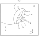
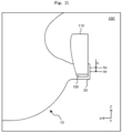
- FIG. 1 is a perspective view of an apparatus for improving propulsion efficiency, which is viewed from the left rear.
- FIG. 2 is a perspective view of a propeller removed in FIG. 1 .
- FIG. 3 is a view of the apparatus for improving the propulsion efficiency, which is viewed from the rear.
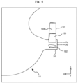
- FIG. 4 is a view of the apparatus for improving the propulsion efficiency, which is viewed from the left side. It is noted that, in FIGS. 1 to 4 , +X means the front, and +Y means the left direction.
- the apparatus 100 for improving the propulsion efficiency includes a duct 110 and pre-swirl stators 131, 132, 133, and 134.
- the duct 110 is disposed in front of a propeller 30.
- the propeller 30 is disposed behind a stern boss 20.
- the propeller 30 rotates to generate thrust.
- the propeller 30 rotates clockwise as seen in FIGS. 1 to 3 .
- the propeller 30 rotates clockwise when viewed from the rear.
- the duct 110 has an arc shape.
- the duct 110 may have an arc shape extending from a lower left area to an upper right area with respect to a centerline A D of an arc formed by the duct 110 as shown in FIGS. 1 to 3 .
- the duct may have an arc shape extending from an upper left area to an upper right area with respect to the centerline of the arc formed by the duct.
- An arc angle of the arc formed by the duct 110 is preferably less than 180 degrees.
- the duct 110 has a structure that partially surrounds the stern boss 20.
- the centerline A D of the arc formed by the duct 110 may be positioned above a rotation axis A P of the propeller 30 as shown in FIG. 4 .
- a distance H between the centerline A D of the arc formed by the duct 110 and the rotation axis A P of the propeller 30 may be equal to or more than 0.4 times of a radius of the propeller 30.
- the range in which the pre-swirl stator may be installed may be significantly limited.
- the distance H between the centerline A D of the arc formed by the duct 110 and the rotation axis A P of the propeller 30 may be 0.1 times or more and 0.4 times or less of the radius of the propeller 30.
- the duct 110 is positioned within a rotational area of the propeller 30.
- a flow that passes through the duct 110 may flow into the propeller 30 in an aligned form, and the propulsion efficiency of the propeller 30 may be improved.
- a radius of the duct 110 is less than or equal to the radius of the propeller minus the distance between the centerline A D of the arc of the duct 110 and the rotation axis A P of the propeller 30.
- the duct 110 generates thrust.
- the duct 110 has an airfoil cross section and has a camber having a convex shape in a direction toward the stern boss 20. This will be described later.
- a lifting force is generated in the cross section of the duct 110 while a flow moving backward along a hull 10 passes through the duct 110.
- a component parallel to a longitudinal direction of the hull 10 (e.g., X-axis direction) of the lifting force acts as thrust for pushing the hull 10.
- the duct 110 may be supported by a stern of the hull 10 by a separate support member (not shown).
- the pre-swirl stators 131, 132, 133, and 134 support the duct 110 with respect to the stern boss 20.
- a plurality of pre-swirl stators 131, 132, 133, and 134 are provided.
- the number of the pre-swirl stators 131, 132, 133, and 134 may be four as shown in FIGS. 1 to 3 .
- the number of the pre-swirl stators may be three or five, although not shown.
- the plurality of pre-swirl stators 131, 132, 133, and 134 are disposed to be spaced apart in the rotation direction of the propeller 30 as shown in FIGS. 1 to 3 .
- the plurality of pre-swirl stators 131, 132, 133, and 134 may be spaced apart in an arc direction about the centerline A D of the arc formed by the duct 110 as shown in FIGS. 2 and 3 .
- the plurality of pre-swirl stators 131, 132, 133, and 134 may be disposed to be spaced apart from each other from the lower left area to the upper right area with respect to the centerline A D of the arc formed by the duct 110 as shown in FIGS. 2 and 3 .
- the plurality of pre-swirl stators may be disposed to be spaced apart from each other from the upper left area to the upper right area with respect to the centerline of the arc formed by the duct.
- the plurality of pre-swirl stators 131, 132, 133, and 134 generate a swirl flow in a direction opposite to the rotation direction of the propeller 30.
- the swirl flow by the pre-swirl stators 131, 132, 133, and 134 flows into the propeller 30 to improve the propulsion efficiency by reducing the swirl flow in the rotation direction of the propeller 30.
- an angle of attack of a flow flowing into the propeller 30 is increased to increase the thrust generated in the propeller 30, thereby improving the propulsion efficiency.
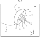
- FIG. 5 is a perspective view of the apparatus for improving the propulsion efficiency, which is viewed from the left rear, in which a cross-sectional shape is added to a duct and a pre-swirl stator.
- the propeller rotates clockwise when viewed from the rear.
- the plurality of pre-swirl stators 131, 132, 133, and 134 have the camber having a convex shape in the rotation direction of the propeller (not shown) as shown in FIG. 5 .
- the apparatus 100 for improving the propulsion efficiency as described above uses the pre-swirl stators 131, 132, 133, and 134 for generating the swirl flow in the direction opposite to the rotation direction of the propeller 30 as a support that supports the duct 110 for generating the thrust with respect to the stern boss 20.
- a simple shaped support member is typically used to support the duct that is disposed in front of the propeller to generate the thrust.
- This simple shaped support member acts as a resistance, which is a factor in increasing the resistance of a ship.
- the apparatus 100 for improving the propulsion uses the pre-swirl stators 131, 132, 133, and 134 to generate the swirl flow in the direction opposite to the rotation direction of the propeller 30 as the support for supporting the duct 110. Therefore, unlike the convention, it increases the thrust of the propeller 30 and improves the propulsion efficiency.
- the number of pre-swirl stators 132, 133, and 134 positioned at a port of the hull 10 among the plurality of pre-swirl stators 131, 132, 133, and 134 is larger than the number of the pre-swirl stators 131 positioned in a starboard.
- the wake occurs in the same direction as the rotation direction of the propeller, and in the starboard, the wake occurs in the direction opposite to the rotation direction of the propeller.
- the pre-swirl stators 132, 133, and 134 may change an inflow flowing into the pre-swirl stators 132, 133, and 134 at a small pitch angle (attachment angle) in the direction opposite to the rotation direction of the propeller 30.
- the inflow flowing into the pre-swirl stator 131 may be changed in the direction opposite to the rotation direction of the propeller 30 only when the pre-swirl stator 131 is installed at a larger pitch angle (attachment angle) than that of the port.
- the increase in resistance due to the attachment of the pre-swirl stators 132, 133, 134 is small in the port that may generate the swirl flow in the direction opposite to the rotation direction of the propeller 30 at the small pitch angle.
- the increase in resistance due to the attachment of the pre-swirl stator 131 becomes excessive in the starboard that may generate the swirl flow in the direction opposite to the rotation direction of the propeller 30 only at the large pitch angle. Therefore, it is desirable to place more pre-swirl stators in the port than the starboard for high propulsion efficiency.
- a first outer end of the duct 110 in the rotation direction of the propeller 30 and a first outer pre-swirl stator 131 positioned last in the rotation direction of the propeller 30 among the plurality of pre-swirl stators 131, 132, 133, and 134 are connected to each other.
- the first outer pre-swirl stator 131 may be positioned in the right upper area with respect to the centerline A D of the arc formed by the duct 110.
- a second outer end of the duct 110 in the rotation direction of the propeller 30 and a second outer pre-swirl stator 132 positioned last in the direction opposite to the rotation direction of the propeller 30 among the plurality of pre-swirl stators 131, 132, 133, and 134 are connected to each other.
- the second outer pre-swirl stator 132 may be positioned in the lower left area with respect to the centerline A D of the arc formed by the duct 110.
- the duct 110 and the first outer pre-swirl stator 131 are different in camber shape.
- the duct 110 has a camber having a convex shape toward the stern boss 20 as shown in FIG. 5
- the first outer pre-swirl stator 131 has a camber having a convex shape in the rotation direction of the propeller 30.
- the duct 110 has the camber having the convex shape toward an inside of a space surrounded by the duct 110, the first outer pre-swirl stator 131, and the second outer pre-swirl stator 132.
- the first outer pre-swirl stator 131 has the camber having the convex shape toward an outside of a space surrounded by the duct 110, the first outer pre-swirl stator 131, and the second outer pre-swirl stator 132.
- the first end of the duct 110 and the first outer pre-swirl stator 131 which have different camber shapes, are continuously connected.
- the first end of the duct 110 and the first outer pre-swirl stator 131 which have the cambers having the convex shape in opposite directions, have a shape that the camber gradually disappears toward its boundary.
- the duct 110 and the second outer pre-swirl stator 132 are identical in camber shape.
- Both the duct 110 and the second outer pre-swirl stator 132 have the camber having the convex shape toward the inside of the space surrounded by the duct 110, the first outer pre-swirl stator 131, and the second outer pre-swirl stator 132.
- the second end of the duct 110 and the second outer pre-swirl stator 132 which have the same camber shape, are continuously connected.
- the first outer pre-swirl stator 131, the second outer pre-swirl stator 132, and the inner pre-swirl stators 133 and 134 may have a swept-back stator shape.
- the first outer pre-swirl stator 131, the second outer pre-swirl stator 132, and the inner pre-swirl stator 133 and 134 have a shape in which a leading edge is struck rearward from a root to a tip.
- the plurality of pre-swirl stators 131, 132, 133, and 134 may each be disposed on the same plane where trailing edges are perpendicular to the centerline A D of the arc formed by the duct 110.
- the plurality of pre-swirl stators 131, 132, 133, and 134 may be as close as possible to the propellers (not shown), and the swirl flow in the direction opposite to the rotation direction of the propeller 30 generated by the pre-swirl stators 131, 132, 133, and 134 may flow directly into the propeller 30, thereby improving the propulsion efficiency .
- the first outer pre-swirl stator 131, the second outer pre-swirl stator 132, and the inner pre-swirl stator 133 and 134 may all have the same length of cord at the root. Further, the first outer pre-swirl stator 131, the second outer pre-swirl stator 132, and the inner pre-swirl stator 133 and 134 may all have the same length of cord at the tip. In addition, the first outer pre-swirl stator 131, the second outer pre-swirl stator 132, and the inner pre-swirl stator 133 and 134 may all have a length of cord at a root greater than a length of cord at a tip.
- the tips of the inner pre-swirl stators 133 and 134 may be fixed to an inner surface of the duct 110.
- front ends of the tips of the inner pre-swirl stators 133 and 134 are positioned behind the leading edge of the duct 110, and rear ends of the tips of the inner pre-swirl stators 133 and 134 are positioned in front of the trailing edge of the duct 110.
- circular rods constituting leading edges of the inner pre-swirl stators 133 and 134 may not interfere with a circular rod constituting the leading edge of the duct 110, and circular rods constituting trailing edges of the inner pre-swirl stators 133 and 134 may not interfere with a circular rod constituting the trailing edge of the duct 110, thereby improving the workability. It is noted that coupling an end of one rod to a side of another rod is much less workable than coupling an end of one rod to a surface of a plate.
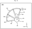
- FIG. 7 is a view showing an exploded view of an outer surface of a combination of the duct, a first outer pre-swirl stator, and a second outer pre-swirl stator according to the apparatus.
- a trailing edge 110b of the duct 110 may have a straight shape, and a leading edge 110a of the duct 110 may have a curved shape that is convex forward.
- the duct 110 having the exploded view as shown in FIG. 7 has a structure in which the peak portion protrudes forward as shown in FIG. 4 .
- the peak portion is closer to the hull 10 so that a short support member (not shown) may support the duct 110 with respect to the hull 10. Since the short support member is structurally larger in strength than a long support member, the duct 110 may be stably supported with respect to the hull 10.
- a curve formed by the leading edge 110a of the duct 110 may have a single curvature R.
- the duct 110 has a shape in which a length of the cord increases and decreases from a first end 110c to a second end 110d.
- the duct has a structure in which plates constituting a pressure surface and a suction surface are coupled to a circular rod constituting the leading edge.
- the circular rod in order to manufacture the duct 110 such that the curve formed by the leading edge 110a of the duct 110 has the single curvature R, the circular rod is bending processed to have one curvature. In this case, comparing to a case where the circular rod is bending processed to have two or more curvatures, the workability is greatly improved.
- the first outer pre-swirl stator 131 has a shape in which the length of the cord decreases from a root 131c to a tip 131d.
- the second outer pre-swirl stator 132 has a shape in which the length of the cord decreases from a root 132c to a tip 132d.
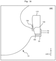
- FIG. 8 is a perspective view of another apparatus for improving the propulsion efficiency, which is viewed from the left rear.
- FIG. 9 is a perspective view of a propeller removed in FIG. 8 .
- FIG. 10 is a view of the another apparatus for improving the propulsion efficiency, which is viewed from the rear.
- FIG. 11 is a view of the another apparatus for improving the propulsion efficiency, which is viewed from the left side.
- FIG. 12 is a perspective view of the another apparatus for improving the propulsion efficiency, which is viewed from the left rear, in which a cross-sectional shape is added to a duct and a pre-swirl stator. It is noted that, in FIGS. 8 to 12 , +X means the front, and +Y means the left direction.
- the another apparatus 100' for improving propulsion efficiency may include the duct 110, the pre-swirl stators 131, 132, 133, and 134, a first connector 150, and a second connector 160.
- the another apparatus 100' for improving propulsion efficiency differs from the apparatus 100 for improving the propulsion efficiency as described above in that it further includes the first connector 150 and the second connector 160.
- the first connector 150 interconnects the first outer end of the duct 110 in the rotation direction of the propeller 30 and the first outer pre-swirl stator 131 positioned last in the rotation direction of the propeller 30 among the plurality of pre-swirl stators 131, 132, 133, and 134.
- the first connector 150 may be manufactured separately from the duct 110 and the first outer pre-swirl stator 131, and both ends of the first connector 150 may be coupled to the first outer pre-swirl stator 131 and the first end of the duct 110, respectively.
- the second connector 160 interconnects the second outer end of the duct 110 in the rotation direction of the propeller 30 and the second outer pre-swirl stator 132 positioned last in the direction opposite to the rotation direction of the propeller 30 among the plurality of pre-swirl stators 131, 132, 133, and 134.
- the second connector 160 may be manufactured separately from the duct 110 and the second outer pre-swirl stator 132, and both ends of the second connector 160 may be coupled to the second outer pre-swirl stator 132 and the second end of the duct 110, respectively.
- the duct 110 and the first outer pre-swirl stator 131 are different in camber shape.
- the duct 110 has a camber having a convex shape toward the stern boss 20 as shown in FIG. 5
- the first outer pre-swirl stator 131 has a camber having a convex shape in the rotation direction of the propeller 30.
- the duct 110 has the camber having the convex shape toward an inside of a space surrounded by the duct 110, the first outer pre-swirl stator 131, and the second outer pre-swirl stator 132.
- the first outer pre-swirl stator 131 has the camber having the convex shape toward an outside of a space surrounded by the duct 110, the first outer pre-swirl stator 131, and the second outer pre-swirl stator 132.
- the first connector 150 has a shape in which the first end of the duct 110 and the first outer pre-swirl stator 131, which have different camber shapes as described above, are continuously connected.
- the first connector 150 includes a first area 151 with the camber having the convex shape in the same direction as the camber of the duct 110 as shown FIG. 5 , and a second area 152 with the camber having the convex shape in the same direction as the camber of the first outer pre-swirl stator 131.
- the cambers of the first area 151 and the second area 152 gradually disappear as they approach the boundary between the first area 151 and the second area 152, respectively.
- the duct 110 and the second outer pre-swirl stator 132 are identical in camber shape.
- the duct 110 has the camber having the convex shape toward the stern boss 20 as shown in FIG. 5
- the second outer pre-swirl stator 132 has the camber having the convex shape in the rotation direction of the propeller 30.
- Both the duct 110 and the second outer pre-swirl stator 132 have the camber having the convex shape toward the inside of the space surrounded by the duct 110, the first outer pre-swirl stator 131, and the second outer pre-swirl stator 132.
- the second connector 160 has a shape in which the second end of the duct 110 and the second outer pre-swirl stator 132, which have the same camber shape, are continuously connected.
- the second connector 160 has a camber having a convex shape toward an inside of the space surrounded by the duct 110, the first outer pre-swirl stator 131, and the second outer pre-swirl stator 160.
- FIG. 13 is a view showing an exploded view of an outer surface of a combination of the duct, a first outer pre-swirl stator, and a second outer pre-swirl stator according to the another apparatus.
- a trailing edge 110b of the duct 110 may have a straight shape, and a leading edge 110a of the duct 110 may have a curved shape that is convex forward.
- a curve formed by the leading edge 110a of the duct 110 may have a single curvature.
- the duct 110 has a shape in which a length of the cord increases and decreases from a first end 110c to a second end 110d.
- the first outer pre-swirl stator 131 has a shape in which the length of the cord decreases from the root 131c to the tip 131d.
- the second outer pre-swirl stator 132 has a shape in which the length of the cord decreases from the root 132c to the tip 132d.
- the first connector 150 has a shape in which the length of the cord decreases and increases from the tip 131d of the first outer pre-swirl stator 131 to the first end 110c of the duct 110.
- a portion where the length of the cord decreases and increases in the first connector 150 becomes the shortest cord 153 in the first connector 150.
- the shortest code 153 of the first connector 150 corresponds to the boundary between the first area (151 of FIG. 10 ) and the second area (152 of FIG. 10 ).
- the second connector 160 may have a shape in which a length of cord decreases and increases from a tip 132d of the second outer pre-swirl stator 132 to a second end 110d of the duct 110.
- Reference numerals 131a, 150a, 110a, 160a, and 132a denote leading edges
- reference numerals 131b, 150b, 110b, 160b and 132b denote trailing edges.
- FIG. 14 is a view of the apparatus for improving the propulsion efficiency according to an embodiment of the present invention, which is viewed from the left side.
- FIG. 15 is a view of a duct removed in FIG. 14 .
- FIG. 16 is a perspective view of the apparatus for improving the propulsion efficiency according to the embodiment of the present invention, which is viewed from the left rear.
- an apparatus 100" for improving propulsion efficiency includes the duct 110, the plurality of pre-swirl stators 131, 132, 133, and 134, the first connector 150, and the second connector 160.
- the apparatus 100" for improving the propulsion efficiency according to the embodiment of the present invention differs from the apparatus 100 for improving the propulsion efficiency in the front and rear positions of the plurality of pre-swirl stators 131, 132, 133, and 134.
- the inner pre-swirl stators 133 and 134 are positioned in front of the first outer pre-swirl stator 131 and the second outer pre-swirl stator 132.
- the front ends of the tips of the inner pre-swirl stators 133 and 134 are also positioned behind the leading edge of the duct 110, and the rear ends of the tips of the inner pre-swirl stators 133 and 134 are also positioned in front of the trailing edge of the duct 110.
- a front-and-rear distance L of the inner pre-swirl stators 133 and 134, the first outer pre-swirl stator 131, and the second outer pre-swirl stator 132 may be 0.05 times or more and 0.15 times or less of a length of cord of a root of the inner pre-swirl stator 133 and 134 or the first outer pre-swirl stator 131 or the second outer pre-swirl stator 132. It is noted that, in this embodiment, lengths of cord of the roots of the inner pre-swirl stators 133 and 134, the first outer pre-swirl stator 131, and the second outer pre-swirl stator 132 are all the same.
- the resistance acting on the hull 10 is reduced compared to a case where the pre-swirl stators 131, 132, 133, and 134 are all positioned at the same position in a longitudinal direction of the hull 10.
- the inner pre-swirl stators 133 and 134 are positioned to be separated from the first outer pre-swirl stator 131 and the second outer pre-swirl stator 132 by a predetermined distance L, such that the Venturi effect generated among the inner pre-swirl stators 133 and 134, the first outer pre-swirl stator 131, and the second outer pre-swirl stator 132 are weakened, thereby reducing the resistance applied to the hull 10.
- the resistance to the hull 10 may increase due to the Venturi effect generated among the inner pre-swirl stators 133 and 134, the first outer pre-swirl stator 131, and the second outer pre-swirl stator 132.
- FIG. 17 is a perspective view of the apparatus for improving the propulsion efficiency according to the embodiment of the present invention, which is viewed from the rear, and FIG. 18 is a view of a propeller removed in FIG. 17 .
- an apparatus 100a for improving propulsion efficiency includes the duct 110 and the plurality of pre-swirl stators 131, 132, 133, and 134.
- the trailing edge 110b of the duct 110 may have a straight shape, and the leading edge 110a of the duct 110 may have a curved shape that is convex forward.
- the duct 110 has a structure in which a peak portion protrudes forward as shown in FIG. 4 .
- the peak portion is closer to the hull 10 so that a short support member (not shown) may support the duct 110 with respect to the hull 10. Since the short support member is structurally larger in strength than a long support member, the duct 110 may be stably supported with respect to the hull 10.
- the separate connectors 150 and 160 may not be included.
- the inner pre-swirl stators 133 and 134 are positioned in front of the first outer pre-swirl stator 131 and the second outer pre-swirl stator 132.
- the front ends of the tips of the inner pre-swirl stators 133 and 134 are also positioned behind the leading edge of the duct 110, and the rear ends of the tips of the inner pre-swirl stators 133 and 134 are positioned in front of the trailing edge of the duct 110.
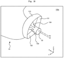
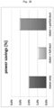
- FIG. 19 is a case in which only the plurality of pre-swirl stators (see 131, 132, 133, and 134 of FIGS. 1 to 18 ) is installed in front of the propeller.
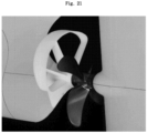
- FIG. 20 is a case in which the plurality of pre-swirl stators and a circular duct (i.e., full duct) are installed in front of the propeller. The circular duct is shaped so as to surround the pre-swirl stator in a circle.
- FIG. 21 is a case in which the plurality of pre-swirl stators and a partial duct are installed in front of the propeller, such as the apparatuses for improving the propulsion efficiency.
- a stator denotes a pre-swirl stator
- a full duct denotes a circular duct
- a partial duct denotes a partial duct
- the case in which only the pre-swirl stators are installed had a 2.0% fuel saving effect compared to the case to be compared.
- the case in which the pre-swirl stators and the circular duct are installed had a 1.0% fuel saving effect compared to the case to be compared.
- the case in which the pre-swirl stators and the partial duct are installed had a 3.0% fuel saving effect compared to the case to be compared.
- FIGS. 23 and 24 it may be seen from FIG. 23 that the hull pressure drop occurs between under the stern boss and the circular duct (see D1). On the other hand, in FIG. 24 , it may be seen that the hull pressure drop does not occur under the stern boss (see D2). When the hull pressure drop occurs, this causes a negative pressure at a lower part of the hull, which increases the hull resistance. Therefore, the fuel saving effect is lowered.
Landscapes
- Chemical & Material Sciences (AREA)
- Engineering & Computer Science (AREA)
- Combustion & Propulsion (AREA)
- Mechanical Engineering (AREA)
- Ocean & Marine Engineering (AREA)
- Structures Of Non-Positive Displacement Pumps (AREA)
Description
- The present invention relates to an apparatus for improving propulsion efficiency.
- Recently, various technologies have been developed to reduce energy consumed in the operation of ships.
- One example of energy saving technology is a duct disposed in front of a propeller.
- The duct generates additional thrust as it passes through a flow moving backwards along a surface of a hull. In this case, the duct may be a factor to increase the propulsion efficiency.
- However, because the duct acts as a resistance on the other side, it is also a factor to reduce the propulsion efficiency.
- Document
KR 2016 0058370 A claim 1. - The present invention is intended to provide an apparatus for improving propulsion efficiency.
- Aspects of the present invention provide an apparatus for improving propulsion efficiency, including: a duct disposed in front of a propeller, having an arc shape, and generating thrust; and a plurality of pre-swirl stators for supporting the duct to a stern boss, the plurality of pre-swirl stators generating a swirl flow in a direction opposite to a rotation direction of the propeller.
- The duct has a camber having a convex shape in a direction toward the stern boss, and the plurality of pre-swirl stators have a camber having a convex shape in the rotation direction of the propeller.
- The apparatus for improving the propulsion efficiency may further include a first connector for interconnecting a first end of the duct in the rotation direction of the propeller and a first outer stator positioned last in the rotation direction of the propeller among the plurality of pre-swirl stators; and a second connector for interconnecting a second end of the duct in the direction opposite to the rotation direction of the propeller and a second outer pre-swirl stator positioned last in the direction opposite to the rotation direction of the propeller among the plurality of pre-swirl stators, in which the first connector may have a shape in which the first end of the duct and the first outer pre-swirl stator, which have different camber shapes, are continuously connected, and in which the second connector may have a shape in which the second end of the duct and the second outer pre-swirl stator, which have the same camber shape, are continuously connected.
- The duct may have an arc shape extending from a lower left area to an upper right area with respect to a centerline of an arc formed by the duct, and the plurality of pre-swirl stators may be disposed to be spaced apart from each other from the lower left area to the upper right area with respect to the centerline of the arc formed by the duct.
- The propeller may rotate clockwise when viewed from the rear, and the number of the pre-swirl stators positioned in a port of a hull among the plurality of pre-swirl stators may be greater than the number of the pre-swirl stators positioned in a starboard.
- The centerline of the arc formed by the duct may be positioned above a rotation axis of the propeller.
- A distance between the centerline of the arc formed by the duct and the rotation axis of the propeller may be 0.1 times or more and 0.4 times or less of a radius of the propeller.
- The duct may be positioned within a rotation area of the propeller.
- Aspects of the present invention also provide an apparatus for improving propulsion efficiency, including: a plurality of pre-swirl stators supported to a stern boss in front of a propeller and generating a swirl flow in a direction opposite to a rotation direction of the propeller; a duct supported to ends of the plurality of pre-swirl stators, having an arc shape, and generating thrust; and a connector for interconnecting the duct and the pre-swirl stators.
- The duct has a camber having a convex shape in a direction toward the stern boss, and the plurality of pre-swirl stators have a camber having a convex shape in the rotation direction of the propeller.
- The connector may further include a first connector for interconnecting a first end of the duct in the rotation direction of the propeller and a first outer stator positioned last in the rotation direction of the propeller among the plurality of pre-swirl stators; and a second connector for interconnecting a second end of the duct in the direction opposite to the rotation direction of the propeller and a second outer pre-swirl stator positioned last in the direction opposite to the rotation direction of the propeller among the plurality of pre-swirl stators, in which the first connector may have a shape in which the first end of the duct and the first outer pre-swirl stator, which have different camber shapes, are continuously connected, and in which the second connector may have a shape in which the second end of the duct and the second outer pre-swirl stator, which have the same camber shape, are continuously connected.
- The first connector and the second connector may be separately manufactured from the duct, the first outer pre-swirl stator, and the second outer pre-swirl stator, respectively, and be coupled to.
- Aspects of the present invention also provide an apparatus for improving propulsion efficiency, including: a duct disposed in front of a propeller, having an arc shape, and generating thrust; and a plurality of pre-swirl stators for supporting the duct to a stern boss, the plurality of pre-swirl stators generating a swirl flow in a direction opposite to a rotation direction of the propeller, in which the duct may have a shape in which a length of cord changes from a first end in the rotation direction of the propeller to a second end in the direction opposite to the rotation direction of the propeller.
- A first outer pre-swirl stator, which is positioned last in the rotation direction of the propeller among the plurality of pre-swirl stators, may have a shape in which a length of cord decreases from a root to a tip, the duct may have a shape in which the length of the cord increases and decreases from the first end in the rotation direction of the propeller to the second end in the direction opposite to the rotation direction of the propeller, and a second outer pre-swirl stator, which is positioned last in the direction opposite to the rotation direction of the propeller among the plurality of pre-swirl stators, may have a shape in which a length of cord decreases from a root to a tip.
- It may further include: a first connector interposed between a first end of the duct in the rotation direction of the propeller and a first outer stator positioned last in the rotation direction of the propeller among the plurality of pre-swirl stators; and a second connector interposed between a second end of the duct in the direction opposite to the rotation direction of the propeller and a second outer pre-swirl stator positioned last in the direction opposite to the rotation direction of the propeller among the plurality of pre-swirl stators, in which the first connector may have a shape in which a length of cord decreases and increases from a tip of the first outer stator to the first end of the duct, and in which the second connector may have a shape in which a length of cord decreases and increases from a tip of the second outer stator to the second end of the duct.
- In an exploded view of one surface facing outward of the duct, a curve formed by a leading edge of the duct may have a single curvature.
- Aspects of the present invention also provide an apparatus for improving propulsion efficiency, including: a duct disposed in front of a propeller, having an arc shape, and generating thrust; and a plurality of pre-swirl stators for supporting the duct to a stern boss, the plurality of pre-swirl stators generating a swirl flow in a direction opposite to a rotation direction of the propeller, in which the plurality of pre-swirl stators are positioned at different positions in a longitudinal direction of a hull.
- An inner pre-swirl stator positioned between a first outer pre-swirl stator positioned last in the rotation direction of the propeller and a second outer pre-swirl stator positioned last in the direction opposite to the rotation direction of the propeller, among the plurality of pre-swirl stators, is positioned in front of the first outer pre-swirl stator and the second outer pre-swirl stator.
- The number of the inner pre-swirl stator may be one or more, in which a front end of a tip of the inner pre-swirl stator fixed to an inner side of the duct may be positioned behind a leading edge of the duct, and a rear end thereof may be positioned in front of a trailing edge of the duct.
- The inner pre-swirl stator, the first outer pre-swirl stator, and the second outer pre-swirl stator may all have the same length of cord at a root and a tip, and a front-and-rear distance of the inner pre-swirl stator, the first outer pre-swirl stator, and the second outer pre-swirl stator may be 0.05 times or more and 0.15 times or less of a length of cord of a root of the inner pre-swirl stator.
- However, aspects of the present invention are not restricted to those set forth herein. The above and other aspects of the present invention will become more apparent to one of ordinary skill in the art to which the present invention pertains by referencing the appended claims, which define the invention.
- According to aspects of the present invention, a pre-swirl stator which generates a swirl flow in a direction opposite to a rotation direction of the propeller is used as a support for supporting a duct, thereby increasing a propeller thrust and improving the propulsion efficiency unlike the conventional method for supporting a duct using a general support structure.
- The above and other aspects and features of the present invention will become more apparent by describing in detail exemplary embodiments thereof with reference to the attached drawings, in which:
-
FIG. 1 is a perspective view of a not claimed apparatus for improving propulsion efficiency, which is viewed from the left rear; -
FIG. 2 is a perspective view of a propeller removed inFIG. 1 ; -
FIG. 3 is a view of the apparatus for improving the propulsion efficiency, which is viewed from the rear; -
FIG. 4 is a view of the apparatus for improving the propulsion efficiency, which is viewed from the left side; -
FIG. 5 is a perspective view of the apparatus for improving the propulsion efficiency, which is viewed from the left rear, in which a cross-sectional shape is added to a duct and a pre-swirl stator; -
FIG. 6 is a view the left side, in which the duct is omitted; -
FIG. 7 is a view showing an exploded view of an outer surface of a combination of the duct, a first outer pre-swirl stator, and a second outer pre-swirl stator; -
FIG. 8 is a perspective view of another apparatus for improving the propulsion efficiency, which is viewed from the left rear; -
FIG. 9 is a perspective view of a propeller removed inFIG. 8 ; -
FIG. 10 is a view of the another apparatus for improving the propulsion efficiency, which is viewed from the rear; -
FIG. 11 is a view of the another apparatus for improving the propulsion efficiency, which is viewed from the left side; -
FIG. 12 is a perspective view of the another apparatus for improving the propulsion efficiency, which is viewed from the left rear, in which a cross-sectional shape is added to a duct and a pre-swirl stator; -
FIG. 13 is a view showing an exploded view of an outer surface of a combination of the duct, a first outer pre-swirl stator, and a second outer pre-swirl stator of the another apparatus for improving the propulsion efficiency; -
FIG. 14 is a view of the apparatus for improving the propulsion efficiency according to the present invention, which is viewed from the left side; -
FIG. 15 is a view of a duct removed inFIG. 14 ; -
FIG. 16 is a perspective view of the apparatus for improving the propulsion efficiency according to the present invention, which is viewed from the left rear; -
FIG. 17 is a perspective view of the apparatus for improving the propulsion efficiency according to the present invention, which is viewed from the rear, andFIG. 18 is a view of a propeller removed inFIG. 17 ; and -
FIGS. 19 to 24 are views for explaining the effect of the apparatus for improving the propulsion efficiency. - The present invention may add various transformations and may have various embodiments. Therefore, specific embodiments will be illustrated in the drawings and described in detail in the detailed description. However, this is not intended to limit the invention to specific embodiments. In describing the present invention, when it is determined that the detailed description of the related known technology may obscure the subject matter of the present invention, the detailed description thereof will be omitted.
- Hereinafter, embodiments of the present invention will be described in detail with reference to the accompanying drawings. In the description with reference to the accompanying drawings, the same or corresponding components will be given the same reference numerals, and redundant description thereof will be omitted.
-
FIG. 1 is a perspective view of an apparatus for improving propulsion efficiency, which is viewed from the left rear.FIG. 2 is a perspective view of a propeller removed inFIG. 1 .FIG. 3 is a view of the apparatus for improving the propulsion efficiency, which is viewed from the rear.FIG. 4 is a view of the apparatus for improving the propulsion efficiency, which is viewed from the left side. It is noted that, inFIGS. 1 to 4 , +X means the front, and +Y means the left direction. - Referring to
FIGS. 1 to 4 , theapparatus 100 for improving the propulsion efficiency includes aduct 110 andpre-swirl stators - The
duct 110 is disposed in front of apropeller 30. Thepropeller 30 is disposed behind astern boss 20. Thepropeller 30 rotates to generate thrust. In this apparatus, thepropeller 30 rotates clockwise as seen inFIGS. 1 to 3 . In other words, thepropeller 30 rotates clockwise when viewed from the rear. - The
duct 110 has an arc shape. - For example, the
duct 110 may have an arc shape extending from a lower left area to an upper right area with respect to a centerline AD of an arc formed by theduct 110 as shown inFIGS. 1 to 3 . - As another example, although not shown, the duct may have an arc shape extending from an upper left area to an upper right area with respect to the centerline of the arc formed by the duct.
- An arc angle of the arc formed by the
duct 110 is preferably less than 180 degrees. - The
duct 110 has a structure that partially surrounds thestern boss 20. - The centerline AD of the arc formed by the
duct 110 may be positioned above a rotation axis AP of thepropeller 30 as shown inFIG. 4 . - Here, a distance H between the centerline AD of the arc formed by the
duct 110 and the rotation axis AP of thepropeller 30 may be equal to or more than 0.4 times of a radius of thepropeller 30. When the distance H between the centerline AD of the arc formed by theduct 110 and the rotation axis AP of thepropeller 30 exceeds 0.4 times of thepropeller 30, the range in which the pre-swirl stator may be installed may be significantly limited. - Further, the distance H between the centerline AD of the arc formed by the
duct 110 and the rotation axis AP of thepropeller 30 may be 0.1 times or more and 0.4 times or less of the radius of thepropeller 30. - The
duct 110 is positioned within a rotational area of thepropeller 30. Here, a flow that passes through theduct 110 may flow into thepropeller 30 in an aligned form, and the propulsion efficiency of thepropeller 30 may be improved. - Here, a radius of the
duct 110 is less than or equal to the radius of the propeller minus the distance between the centerline AD of the arc of theduct 110 and the rotation axis AP of thepropeller 30. - The
duct 110 generates thrust. For example, theduct 110 has an airfoil cross section and has a camber having a convex shape in a direction toward thestern boss 20. This will be described later. - A lifting force is generated in the cross section of the
duct 110 while a flow moving backward along ahull 10 passes through theduct 110. A component parallel to a longitudinal direction of the hull 10 (e.g., X-axis direction) of the lifting force acts as thrust for pushing thehull 10. - The
duct 110 may be supported by a stern of thehull 10 by a separate support member (not shown). - The
pre-swirl stators duct 110 with respect to thestern boss 20. - A plurality of
pre-swirl stators - For example, the number of the
pre-swirl stators FIGS. 1 to 3 . - As another example, the number of the pre-swirl stators may be three or five, although not shown.
- The plurality of
pre-swirl stators propeller 30 as shown inFIGS. 1 to 3 . In other words, the plurality ofpre-swirl stators duct 110 as shown inFIGS. 2 and3 . - For example, the plurality of
pre-swirl stators duct 110 as shown inFIGS. 2 and3 . - As another example, although not illustrated, the plurality of pre-swirl stators may be disposed to be spaced apart from each other from the upper left area to the upper right area with respect to the centerline of the arc formed by the duct.
- The plurality of
pre-swirl stators propeller 30. - The swirl flow by the
pre-swirl stators propeller 30 to improve the propulsion efficiency by reducing the swirl flow in the rotation direction of thepropeller 30. In other words, when the swirl flow in the direction opposite to the rotation direction of thepropeller 30 is generated by thepre-swirl stators propeller 30 is increased to increase the thrust generated in thepropeller 30, thereby improving the propulsion efficiency. -
FIG. 5 is a perspective view of the apparatus for improving the propulsion efficiency, which is viewed from the left rear, in which a cross-sectional shape is added to a duct and a pre-swirl stator. - Referring to
FIG. 5 , in the apparatus, the propeller (not shown) rotates clockwise when viewed from the rear. Here, in order to generate the swirl flow in the direction opposite to the rotation direction of the propeller (not shown), the plurality ofpre-swirl stators FIG. 5 . - The
apparatus 100 for improving the propulsion efficiency as described above uses thepre-swirl stators propeller 30 as a support that supports theduct 110 for generating the thrust with respect to thestern boss 20. - In this regard, unlike the
pre-swirl stators - However, the
apparatus 100 for improving the propulsion uses thepre-swirl stators propeller 30 as the support for supporting theduct 110. Therefore, unlike the convention, it increases the thrust of thepropeller 30 and improves the propulsion efficiency. - In this apparatus, the number of
pre-swirl stators hull 10 among the plurality ofpre-swirl stators pre-swirl stators 131 positioned in a starboard. - More specifically, typically, looking into the distribution of wake into the propeller in a barehull state without the pre-swirl stator, in the port, the wake occurs in the same direction as the rotation direction of the propeller, and in the starboard, the wake occurs in the direction opposite to the rotation direction of the propeller.
- In the port where the wake in the same direction as the rotation direction of the
propeller 30 is generated, thepre-swirl stators pre-swirl stators propeller 30. However, in the starboard where the wake in the direction opposite to the rotation direction of thepropeller 30 is generated, the inflow flowing into thepre-swirl stator 131 may be changed in the direction opposite to the rotation direction of thepropeller 30 only when thepre-swirl stator 131 is installed at a larger pitch angle (attachment angle) than that of the port. - In this case, the increase in resistance due to the attachment of the
pre-swirl stators propeller 30 at the small pitch angle. However, the increase in resistance due to the attachment of thepre-swirl stator 131 becomes excessive in the starboard that may generate the swirl flow in the direction opposite to the rotation direction of thepropeller 30 only at the large pitch angle. Therefore, it is desirable to place more pre-swirl stators in the port than the starboard for high propulsion efficiency. - In this apparatus, a first outer end of the
duct 110 in the rotation direction of thepropeller 30 and a first outerpre-swirl stator 131 positioned last in the rotation direction of thepropeller 30 among the plurality ofpre-swirl stators FIG. 3 , the first outerpre-swirl stator 131 may be positioned in the right upper area with respect to the centerline AD of the arc formed by theduct 110. - A second outer end of the
duct 110 in the rotation direction of thepropeller 30 and a second outerpre-swirl stator 132 positioned last in the direction opposite to the rotation direction of thepropeller 30 among the plurality ofpre-swirl stators FIG. 3 , the second outerpre-swirl stator 132 may be positioned in the lower left area with respect to the centerline AD of the arc formed by theduct 110. - In this apparatus, the
duct 110 and the first outerpre-swirl stator 131 are different in camber shape. - More specifically, the
duct 110 has a camber having a convex shape toward thestern boss 20 as shown inFIG. 5 , and the first outerpre-swirl stator 131 has a camber having a convex shape in the rotation direction of thepropeller 30. - In other words, the
duct 110 has the camber having the convex shape toward an inside of a space surrounded by theduct 110, the first outerpre-swirl stator 131, and the second outerpre-swirl stator 132. The first outerpre-swirl stator 131 has the camber having the convex shape toward an outside of a space surrounded by theduct 110, the first outerpre-swirl stator 131, and the second outerpre-swirl stator 132. - In this apparatus, as described above, the first end of the
duct 110 and the first outerpre-swirl stator 131, which have different camber shapes, are continuously connected. - For example, as shown in
FIG. 5 , the first end of theduct 110 and the first outerpre-swirl stator 131, which have the cambers having the convex shape in opposite directions, have a shape that the camber gradually disappears toward its boundary. - In this apparatus, the
duct 110 and the second outerpre-swirl stator 132 are identical in camber shape. - More specifically, the
duct 110 has the camber having the convex shape toward thestern boss 20 as shown inFIG. 5 , and the second outerpre-swirl stator 132 has the camber having the convex shape in the rotation direction of thepropeller 30. - In other words, Both the
duct 110 and the second outerpre-swirl stator 132 have the camber having the convex shape toward the inside of the space surrounded by theduct 110, the first outerpre-swirl stator 131, and the second outerpre-swirl stator 132. - In this apparatus, as described above, the second end of the
duct 110 and the second outerpre-swirl stator 132, which have the same camber shape, are continuously connected. -
FIG. 6 is a view showing a part according to the apparatus, which is viewed from the left side, in which the duct is omitted. - Referring to
FIGS. 5 and6 , the first outerpre-swirl stator 131, the second outerpre-swirl stator 132, and the innerpre-swirl stators pre-swirl stator 131, the second outerpre-swirl stator 132, and the innerpre-swirl stator - In this apparatus, the plurality of
pre-swirl stators duct 110. Here, the plurality ofpre-swirl stators propeller 30 generated by thepre-swirl stators propeller 30, thereby improving the propulsion efficiency . - In this apparatus, the first outer
pre-swirl stator 131, the second outerpre-swirl stator 132, and the innerpre-swirl stator pre-swirl stator 131, the second outerpre-swirl stator 132, and the innerpre-swirl stator pre-swirl stator 131, the second outerpre-swirl stator 132, and the innerpre-swirl stator - Referring to
FIG. 5 , in this apparatus, the tips of the innerpre-swirl stators duct 110. - Here, front ends of the tips of the inner
pre-swirl stators duct 110, and rear ends of the tips of the innerpre-swirl stators duct 110. - In this case, circular rods constituting leading edges of the inner
pre-swirl stators duct 110, and circular rods constituting trailing edges of the innerpre-swirl stators duct 110, thereby improving the workability. It is noted that coupling an end of one rod to a side of another rod is much less workable than coupling an end of one rod to a surface of a plate. -
FIG. 7 is a view showing an exploded view of an outer surface of a combination of the duct, a first outer pre-swirl stator, and a second outer pre-swirl stator according to the apparatus. - Referring to
FIG. 7 , in the exploded view, a trailingedge 110b of theduct 110 may have a straight shape, and aleading edge 110a of theduct 110 may have a curved shape that is convex forward. - In this case, the most convex peak portion in the exploded view of the
duct 110 approaches thehull 10, so that theduct 110 is easily fixed to thehull 10. - More specifically, the
duct 110 having the exploded view as shown inFIG. 7 has a structure in which the peak portion protrudes forward as shown inFIG. 4 . Here, the peak portion is closer to thehull 10 so that a short support member (not shown) may support theduct 110 with respect to thehull 10. Since the short support member is structurally larger in strength than a long support member, theduct 110 may be stably supported with respect to thehull 10. - Referring to
FIG. 7 , in the exploded view, a curve formed by theleading edge 110a of theduct 110 may have a single curvature R. In this case, theduct 110 has a shape in which a length of the cord increases and decreases from afirst end 110c to asecond end 110d. - Typically, the duct has a structure in which plates constituting a pressure surface and a suction surface are coupled to a circular rod constituting the leading edge.
- In the exploded view, in order to manufacture the
duct 110 such that the curve formed by theleading edge 110a of theduct 110 has the single curvature R, the circular rod is bending processed to have one curvature. In this case, comparing to a case where the circular rod is bending processed to have two or more curvatures, the workability is greatly improved. - Referring to
FIG. 7 , the first outerpre-swirl stator 131 has a shape in which the length of the cord decreases from aroot 131c to atip 131d. The second outerpre-swirl stator 132 has a shape in which the length of the cord decreases from aroot 132c to atip 132d. -
FIG. 8 is a perspective view of another apparatus for improving the propulsion efficiency, which is viewed from the left rear.FIG. 9 is a perspective view of a propeller removed inFIG. 8 .FIG. 10 is a view of the another apparatus for improving the propulsion efficiency, which is viewed from the rear.FIG. 11 is a view of the another apparatus for improving the propulsion efficiency, which is viewed from the left side.FIG. 12 is a perspective view of the another apparatus for improving the propulsion efficiency, which is viewed from the left rear, in which a cross-sectional shape is added to a duct and a pre-swirl stator. It is noted that, inFIGS. 8 to 12 , +X means the front, and +Y means the left direction. - Referring to
FIGS. 8 to 12 , the another apparatus 100' for improving propulsion efficiency may include theduct 110, thepre-swirl stators first connector 150, and asecond connector 160. The another apparatus 100' for improving propulsion efficiency differs from theapparatus 100 for improving the propulsion efficiency as described above in that it further includes thefirst connector 150 and thesecond connector 160. - The
first connector 150 interconnects the first outer end of theduct 110 in the rotation direction of thepropeller 30 and the first outerpre-swirl stator 131 positioned last in the rotation direction of thepropeller 30 among the plurality ofpre-swirl stators - The
first connector 150 may be manufactured separately from theduct 110 and the first outerpre-swirl stator 131, and both ends of thefirst connector 150 may be coupled to the first outerpre-swirl stator 131 and the first end of theduct 110, respectively. - The
second connector 160 interconnects the second outer end of theduct 110 in the rotation direction of thepropeller 30 and the second outerpre-swirl stator 132 positioned last in the direction opposite to the rotation direction of thepropeller 30 among the plurality ofpre-swirl stators - The
second connector 160 may be manufactured separately from theduct 110 and the second outerpre-swirl stator 132, and both ends of thesecond connector 160 may be coupled to the second outerpre-swirl stator 132 and the second end of theduct 110, respectively. - In this apparatus, the
duct 110 and the first outerpre-swirl stator 131 are different in camber shape. - More specifically, the
duct 110 has a camber having a convex shape toward thestern boss 20 as shown inFIG. 5 , and the first outerpre-swirl stator 131 has a camber having a convex shape in the rotation direction of thepropeller 30. - In other words, the
duct 110 has the camber having the convex shape toward an inside of a space surrounded by theduct 110, the first outerpre-swirl stator 131, and the second outerpre-swirl stator 132. The first outerpre-swirl stator 131 has the camber having the convex shape toward an outside of a space surrounded by theduct 110, the first outerpre-swirl stator 131, and the second outerpre-swirl stator 132. - The
first connector 150 according to this apparatus has a shape in which the first end of theduct 110 and the first outerpre-swirl stator 131, which have different camber shapes as described above, are continuously connected. - For example, the
first connector 150 includes afirst area 151 with the camber having the convex shape in the same direction as the camber of theduct 110 as shownFIG. 5 , and asecond area 152 with the camber having the convex shape in the same direction as the camber of the first outerpre-swirl stator 131. The cambers of thefirst area 151 and thesecond area 152 gradually disappear as they approach the boundary between thefirst area 151 and thesecond area 152, respectively. - In this embodiment, the
duct 110 and the second outerpre-swirl stator 132 are identical in camber shape. - More specifically, the
duct 110 has the camber having the convex shape toward thestern boss 20 as shown inFIG. 5 , and the second outerpre-swirl stator 132 has the camber having the convex shape in the rotation direction of thepropeller 30. - In other words, Both the
duct 110 and the second outerpre-swirl stator 132 have the camber having the convex shape toward the inside of the space surrounded by theduct 110, the first outerpre-swirl stator 131, and the second outerpre-swirl stator 132. - The
second connector 160 according to this apparatus has a shape in which the second end of theduct 110 and the second outerpre-swirl stator 132, which have the same camber shape, are continuously connected. - For example, as shown in
FIG. 5 , thesecond connector 160 has a camber having a convex shape toward an inside of the space surrounded by theduct 110, the first outerpre-swirl stator 131, and the second outerpre-swirl stator 160. -
FIG. 13 is a view showing an exploded view of an outer surface of a combination of the duct, a first outer pre-swirl stator, and a second outer pre-swirl stator according to the another apparatus. - Referring to
FIG. 13 , in the exploded view, a trailingedge 110b of theduct 110 may have a straight shape, and aleading edge 110a of theduct 110 may have a curved shape that is convex forward. - In this case, the most convex peak portion in the exploded view of the
duct 110 approaches thehull 10, so that theduct 110 is easily fixed to thehull 10. - Referring to
FIG. 13 , in the exploded view, a curve formed by theleading edge 110a of theduct 110 may have a single curvature. In this case, theduct 110 has a shape in which a length of the cord increases and decreases from afirst end 110c to asecond end 110d. - Referring to
FIG. 13 , the first outerpre-swirl stator 131 has a shape in which the length of the cord decreases from theroot 131c to thetip 131d. The second outerpre-swirl stator 132 has a shape in which the length of the cord decreases from theroot 132c to thetip 132d. - Further, the
first connector 150 has a shape in which the length of the cord decreases and increases from thetip 131d of the first outerpre-swirl stator 131 to thefirst end 110c of theduct 110. In particular, a portion where the length of the cord decreases and increases in thefirst connector 150 becomes theshortest cord 153 in thefirst connector 150. Theshortest code 153 of thefirst connector 150 corresponds to the boundary between the first area (151 ofFIG. 10 ) and the second area (152 ofFIG. 10 ). Thesecond connector 160 may have a shape in which a length of cord decreases and increases from atip 132d of the second outerpre-swirl stator 132 to asecond end 110d of theduct 110. -
Reference numerals reference numerals -
FIG. 14 is a view of the apparatus for improving the propulsion efficiency according to an embodiment of the present invention, which is viewed from the left side.FIG. 15 is a view of a duct removed inFIG. 14 .FIG. 16 is a perspective view of the apparatus for improving the propulsion efficiency according to the embodiment of the present invention, which is viewed from the left rear. - Referring to
FIGS. 14 to 16 , anapparatus 100" for improving propulsion efficiency according to the embodiment of the present invention includes theduct 110, the plurality ofpre-swirl stators first connector 150, and thesecond connector 160. - The
apparatus 100" for improving the propulsion efficiency according to the embodiment of the present invention differs from theapparatus 100 for improving the propulsion efficiency in the front and rear positions of the plurality ofpre-swirl stators - In this embodiment, the inner
pre-swirl stators pre-swirl stator 131 and the second outerpre-swirl stator 132. - Here, the front ends of the tips of the inner
pre-swirl stators duct 110, and the rear ends of the tips of the innerpre-swirl stators duct 110. - In this embodiment, a front-and-rear distance L of the inner
pre-swirl stators pre-swirl stator 131, and the second outerpre-swirl stator 132 may be 0.05 times or more and 0.15 times or less of a length of cord of a root of the innerpre-swirl stator pre-swirl stator 131 or the second outerpre-swirl stator 132. It is noted that, in this embodiment, lengths of cord of the roots of the innerpre-swirl stators pre-swirl stator 131, and the second outerpre-swirl stator 132 are all the same. - As described above, when the inner
pre-swirl stators pre-swirl stator 131 and the second outerpre-swirl stator 132, the resistance acting on thehull 10 is reduced compared to a case where thepre-swirl stators hull 10. - This is because the inner
pre-swirl stators pre-swirl stator 131 and the second outerpre-swirl stator 132 by a predetermined distance L, such that the Venturi effect generated among the innerpre-swirl stators pre-swirl stator 131, and the second outerpre-swirl stator 132 are weakened, thereby reducing the resistance applied to thehull 10. - When the front-and-rear distance of the inner
pre-swirl stators pre-swirl stator 131, and the second outerpre-swirl stator 132 exceed the range, a distance between the innerpre-swirl stators pre-swirl stators - When the front-and-rear distance of the inner
pre-swirl stators pre-swirl stator 131, and the second outerpre-swirl stator 132 are smaller than the range, the resistance to thehull 10 may increase due to the Venturi effect generated among the innerpre-swirl stators pre-swirl stator 131, and the second outerpre-swirl stator 132. -
FIG. 17 is a perspective view of the apparatus for improving the propulsion efficiency according to the embodiment of the present invention, which is viewed from the rear, andFIG. 18 is a view of a propeller removed inFIG. 17 . - Referring to
FIGS. 17 and18 , anapparatus 100a for improving propulsion efficiency according to the embodiment of the present invention includes theduct 110 and the plurality ofpre-swirl stators - As described using
FIG. 7 , in an exploded view of theduct 110, the trailingedge 110b of theduct 110 may have a straight shape, and theleading edge 110a of theduct 110 may have a curved shape that is convex forward. Theduct 110 has a structure in which a peak portion protrudes forward as shown inFIG. 4 . Here, the peak portion is closer to thehull 10 so that a short support member (not shown) may support theduct 110 with respect to thehull 10. Since the short support member is structurally larger in strength than a long support member, theduct 110 may be stably supported with respect to thehull 10. Unlike those described inFIGS. 8 to 16 , theseparate connectors - As described in
FIGS. 14 to 16 , the innerpre-swirl stators pre-swirl stator 131 and the second outerpre-swirl stator 132. - The front ends of the tips of the inner
pre-swirl stators duct 110, and the rear ends of the tips of the innerpre-swirl stators duct 110. - As described above, when the inner
pre-swirl stators pre-swirl stator 131 and the second outerpre-swirl stator 132, the resistance acting on thehull 10 is reduced compared to a case where thepre-swirl stators hull 10. - Hereinafter, referring to
FIGS. 19 to 22 , the fuel saving effect of theapparatuses - First,
FIG. 19 is a case in which only the plurality of pre-swirl stators (see 131, 132, 133, and 134 ofFIGS. 1 to 18 ) is installed in front of the propeller.FIG. 20 is a case in which the plurality of pre-swirl stators and a circular duct (i.e., full duct) are installed in front of the propeller. The circular duct is shaped so as to surround the pre-swirl stator in a circle.FIG. 21 is a case in which the plurality of pre-swirl stators and a partial duct are installed in front of the propeller, such as the apparatuses for improving the propulsion efficiency. - The case in which only the pre-swirl stators are installed (
FIG. 19 ), the case in which the pre-swirl stators and the circular duct are installed (FIG. 20 ), and the case in which the pre-swirl stators and the partial duct are installed (FIG. 21 ) are compared with a case in which only the propeller is installed (i.e., a case to be compared). Then, the fuel savings effect was tested and the results are shown inFIG. 22 . InFIG. 22 , a stator denotes a pre-swirl stator, a full duct denotes a circular duct, and a partial duct denotes a partial duct. - Referring to
FIG. 22 , the case in which only the pre-swirl stators are installed (FIG. 19 ) had a 2.0% fuel saving effect compared to the case to be compared. The case in which the pre-swirl stators and the circular duct are installed (FIG. 20 ) had a 1.0% fuel saving effect compared to the case to be compared. The case in which the pre-swirl stators and the partial duct are installed (FIG. 21 ) had a 3.0% fuel saving effect compared to the case to be compared. - In order to confirm why the fuel saving effect of the case in which the pre-swirl stators and the circular ducts are installed (
FIG. 20 ) is relatively low compared to other cases, additional tests were made and the results are shown inFIGS. 23 and24 . - Comparing
FIGS. 23 and24 , it may be seen fromFIG. 23 that the hull pressure drop occurs between under the stern boss and the circular duct (see D1). On the other hand, inFIG. 24 , it may be seen that the hull pressure drop does not occur under the stern boss (see D2). When the hull pressure drop occurs, this causes a negative pressure at a lower part of the hull, which increases the hull resistance. Therefore, the fuel saving effect is lowered. - Compared to the case in which only the pre-swirl stators are installed (
FIG. 19 ), the reason why the fuel saving effect of the case in which the pre-swirl stator and the partial duct are installed (FIG. 21 ) is good is as follows. - In the case using the duct (
FIG. 21 ), all pre-swirl stators are connected to the partial duct in a multipoint support structure (i.e., a multiple support). Therefore, the case using the partial duct (FIG. 21 ) has a higher structural stability than the case in which only the cantilever type pre-swirl stators are installed (FIG. 19 ). - In addition, in the pre-swirl stator which generates the swirl flow, cavitation due to end vortex may occur. Therefore, in the case in which only the pre-swirl stators are installed (
FIG. 19 ), an additional shape such as a winglet should be mounted in order to reduce the cavitation of ends. However, since the case using the partial duct (FIG. 21 ) has a shape in which all the pre-swirl stators are surrounded by the partial duct, the end vortex is essentially blocked. Therefore, no additional device such as the winglet is needed. - In the above, an embodiment of the present invention has been described. However, those skilled in the art may variously modify and change the present invention by adding, changing, deleting, or adding components within the scope defined by the claims.
-
- 10: hull
- 20: stern boss
- 30: propeller
- 100: apparatus for improving propulsion efficiency
- 110: duct
- 131: first outer pre-swirl stator
- 132: second outer pre-swirl stator
- 133, 134: inner pre-swirl stator
- 150: first connector
- 160: second connector
Claims (15)
- An apparatus (100) for improving propulsion efficiency, comprising:a duct (110) configured to be disposed in front of a propeller (30), having an arc shape, and generating thrust; anda plurality of pre-swirl stators (131-134) for supporting the duct (110) configured to be fixed to a stern boss (20), the plurality of pre-swirl stators (131-134) generating a swirl flow in a direction opposite to a rotation direction of the propeller (30),whereinthe duct (110) has a camber of convex shape toward the stern boss (20), andthe plurality of pre-swirl stators (131-134) have a camber having a convex shape in the rotation direction of the propeller (30), wherein the first outer pre-swirl stator (131) is positioned last in the rotation direction of the propeller (30) among the plurality of pre-swirl stators (131-134),characterized in that the camber of the duct (110) and the camber of the first outer pre-swirl stator (131) gradually disappear towards the boundary of the duct (110) and the first pre-swirl stator (131),wherein the duct (110) and the first outer swirl stator (131) are different in camber shape, andwherein when the duct (110) and the plurality of pre-swirl stators (131-134) are viewed from the side, the contact part between inner pre-swirl stators (133-134) and the stern boss (20) is exposed to the outside in front of the duct (110).
- The apparatus (100) of claim 1, further comprising:a first connector (150 for interconnecting a first end (110c) of the duct (110) in the rotation direction of the propeller (30) and a first outer pre-swirl stator (131) positioned last in the rotation direction of the propeller (30) among the plurality of pre-swirl stators (131-134); anda second connector (160) for interconnecting a second end (110d) of the duct (110) in the direction opposite to the rotation direction of the propeller (30) and a second outer pre-swirl stator (132) positioned last in the direction opposite to the rotation direction of the propeller (30) among the plurality of pre-swirl stators (131-134),wherein the first connector (150) has a shape in which the first end (110c) of the duct (110) and the first outer pre-swirl stator (131), which have different camber shapes, are continuously connected, andwherein the second connector (160) has a shape in which the second end (110d) of the duct (110) and the second outer pre-swirl stator (132), which have the same camber shape, are continuously connected.
- The apparatus (100) of claim 1, wherein the duct (110) has an arc shape extending from a lower left area to an upper right area with respect to a centerline of an arc formed by the duct (110), and
wherein the plurality of pre-swirl stators (131-134) are disposed to be spaced apart from each other from the lower left area to the upper right area with respect to the centerline of the arc formed by the duct (110). - The apparatus (100) of claim 1, wherein the propeller (30) rotates clockwise when viewed from the rear, and
wherein the number of the pre-swirl stators (131-134) positioned in a port of a hull (10) among the plurality of pre-swirl stators (131-134) is greater than the number of the pre-swirl stators (131-134) positioned in a starboard. - The apparatus (100) of claim 1, wherein a centerline of an arc formed by the duct (110) is positioned above a rotation axis of the propeller (30).
- The apparatus (100) of claim 1, wherein a distance between a centerline of an arc formed by the duct (110) and a rotation axis of the propeller (30) is 0.1 times or more and 0.4 times or less of a radius of the propeller (30).
- The apparatus (100) of claim 1, wherein the duct (110) is positioned within a rotation area of the propeller (30).
- The apparatus (100) of claim 1, further comprising:
a connector for interconnecting the duct (110) and the pre-swirl stators (131-134). - The apparatus (100) of claim 8, wherein the duct (110) has a camber having a convex shape in a direction toward the stern boss (20), and
wherein the plurality of pre-swirl stators (131-134) have a camber having a convex shape in the rotation direction of the propeller (30). - The apparatus (100) of claim 9, wherein the connector further comprises:a first connector (150) for interconnecting a first end (110c) of the duct (110) in the rotation direction of the propeller (30) and a first outer pre-swirl stator (131) positioned last in the rotation direction of the propeller (30) among the plurality of pre-swirl stators (131-134); anda second connector (160) for interconnecting a second end (110d) of the duct (110) in the direction opposite to the rotation direction of the propeller (30) and a second outer pre-swirl stator (132) positioned last in the direction opposite to the rotation direction of the propeller (30) among the plurality of pre-swirl stators (131-134),wherein the first connector (150) has a shape in which the first end (110c) of the duct (110) and the first outer pre-swirl stator (131), which have different camber shapes, are continuously connected, andwherein the second connector (160) has a shape in which the second end (110d) of the duct (110) and the second outer pre-swirl stator (132), which have the same camber shape, are continuously connected.
- The apparatus (100) of claim 10, wherein the first connector (150) and the second connector (160) are separately manufactured from the duct (110), the first outer pre-swirl stator (131), and the second outer pre-swirl stator (132), respectively, and are coupled to the duct (110).
- The apparatus (100) of claim 1, further comprising:
wherein the plurality of pre-swirl stators (131-134) are positioned at different positions in a longitudinal direction of a hull (10). - The apparatus (100) of claim 12, wherein an inner pre-swirl stator (133-134) positioned between a first outer pre-swirl stator (131) positioned last in the rotation direction of the propeller (30) and a second outer pre-swirl stator (132) positioned last in the direction opposite to the rotation direction of the propeller (30), among the plurality of pre-swirl stators (131-134), is positioned in front of the first outer pre-swirl stator (131) and the second outer pre-swirl stator (132).
- The apparatus (100) of claim 13, wherein the number of the inner pre-swirl stators (133-134) is one or more, and
wherein a front end of a tip of the inner pre-swirl stator (133-134) fixed to an inner side of the duct (110) is positioned behind a leading edge (110a) of the duct (110), and a rear end thereof is positioned in front of a trailing edge (110b) of the duct (110). - The apparatus (100) of claim 13, wherein the inner pre-swirl stator (133-134), the first outer pre-swirl stator (131), and the second outer pre-swirl stator (132) all have the same length of cord at a root and a tip, and
wherein a front-and-rear distance of the inner pre-swirl stator (133-134), the first outer pre-swirl stator (131), and the second outer pre-swirl (132) stator is 0.05 times or more and 0.15 times or less of a length of cord of a root of the inner pre-swirl stator (133-134).
Applications Claiming Priority (5)
| Application Number | Priority Date | Filing Date | Title |
|---|---|---|---|
| KR1020170143359A KR102027271B1 (en) | 2017-10-31 | 2017-10-31 | Propulsion efficiency enhancing apparatus |
| KR1020170143239A KR102027269B1 (en) | 2017-10-31 | 2017-10-31 | Propulsion efficiency enhancing apparatus |
| KR1020170143315A KR102027270B1 (en) | 2017-10-31 | 2017-10-31 | Propulsion efficiency enhancing apparatus |
| KR1020170143470A KR20190048483A (en) | 2017-10-31 | 2017-10-31 | Propulsion efficiency enhancing apparatus |
| PCT/KR2018/013108 WO2019088696A1 (en) | 2017-10-31 | 2018-10-31 | Apparatus for enhancing propulsion efficiency |
Publications (4)
| Publication Number | Publication Date |
|---|---|
| EP3705392A1 EP3705392A1 (en) | 2020-09-09 |
| EP3705392A4 EP3705392A4 (en) | 2021-08-04 |
| EP3705392B1 true EP3705392B1 (en) | 2025-03-05 |
| EP3705392C0 EP3705392C0 (en) | 2025-03-05 |
Family
ID=66332409
Family Applications (1)
| Application Number | Title | Priority Date | Filing Date |
|---|---|---|---|
| EP18872708.5A Active EP3705392B1 (en) | 2017-10-31 | 2018-10-31 | Apparatus for enhancing propulsion efficiency |
Country Status (6)
| Country | Link |
|---|---|
| EP (1) | EP3705392B1 (en) |
| JP (1) | JP7145945B2 (en) |
| CN (1) | CN111295329A (en) |
| ES (1) | ES3015733T3 (en) |
| SG (1) | SG11202003855RA (en) |
| WO (1) | WO2019088696A1 (en) |
Families Citing this family (5)
| Publication number | Priority date | Publication date | Assignee | Title |
|---|---|---|---|---|
| CN111086611A (en) * | 2018-10-23 | 2020-05-01 | 东辉休闲运动用品(上海)有限公司 | underwater thruster |
| US20230202628A1 (en) * | 2020-05-28 | 2023-06-29 | Becker Marine Systems Gmbh | Arrangement to reduce a propulsion power requirement of a watercraft |
| EP4155190A1 (en) * | 2021-09-23 | 2023-03-29 | Damen Components Holding B.V. | Flow-guiding system for a ship propulsion system |
| CN115416832A (en) * | 2022-09-05 | 2022-12-02 | 大连中远海运重工有限公司 | Spiral honeycomb duct energy-saving device for ship |
| CN116280136A (en) * | 2023-03-20 | 2023-06-23 | 中船重工(上海)节能技术发展有限公司 | Wake self-adaptive pre-swirl guide wheel and its control method |
Citations (17)
| Publication number | Priority date | Publication date | Assignee | Title |
|---|---|---|---|---|
| JP2008239060A (en) * | 2007-03-28 | 2008-10-09 | Mitsui Eng & Shipbuild Co Ltd | Stern horizontal duct and ship |
| KR20100103982A (en) * | 2009-03-16 | 2010-09-29 | 대우조선해양 주식회사 | Pre-swirl stator of ship |
| KR20120094763A (en) * | 2011-02-17 | 2012-08-27 | 충남대학교산학협력단 | Ducted-propeller with pre-swirl stator for vessels |
| KR20120126910A (en) * | 2011-05-13 | 2012-11-21 | 현대중공업 주식회사 | Propeller Duct Structure of Ship with Multi-Column Fin |
| KR20140137620A (en) | 2013-05-23 | 2014-12-03 | 현대중공업 주식회사 | Vessel including stern duct structure |
| WO2015012490A1 (en) | 2013-07-26 | 2015-01-29 | 부산대학교 산학협력단 | Thrust force improvement apparatus for ship |
| KR20150013962A (en) | 2013-07-24 | 2015-02-06 | 현대중공업 주식회사 | Propulsion improving apparatus of ship |
| WO2015093048A1 (en) | 2013-12-16 | 2015-06-25 | 独立行政法人海上技術安全研究所 | Stern duct, stern attachment, method of designing stern duct, and ship equipped with stern duct |
| KR20160000326A (en) | 2014-06-24 | 2016-01-04 | 현대중공업 주식회사 | Ship propulsion unit that apply asymmetry duct |
| KR20160000450A (en) | 2015-10-13 | 2016-01-04 | 현대중공업 주식회사 | Ship propulsion unit that apply duct |
| KR20160002232A (en) | 2014-06-30 | 2016-01-07 | 현대중공업 주식회사 | Ship propulsion unit that rectifier unit is applied |
| KR20160032475A (en) * | 2014-09-16 | 2016-03-24 | 현대중공업 주식회사 | Duct for ship |
| KR20160058370A (en) * | 2014-11-14 | 2016-05-25 | 한국해양과학기술원 | Asymmetric fan-shaped duct for energy saving of ship |
| KR20160149877A (en) | 2015-06-19 | 2016-12-28 | 현대중공업 주식회사 | A propulsion apparatus for ship |
| WO2017038862A1 (en) | 2015-08-31 | 2017-03-09 | 国立研究開発法人 海上・港湾・航空技術研究所 | Ship and stern shape having stern duct |
| EP3210876A1 (en) | 2014-10-24 | 2017-08-30 | Samsung Heavy Ind. Co., Ltd. | Propelling efficiency enhancing device |
| KR20180083463A (en) | 2017-01-12 | 2018-07-23 | 성동조선해양(주) | Pre-swirl stator including annular structure |
Family Cites Families (7)
| Publication number | Priority date | Publication date | Assignee | Title |
|---|---|---|---|---|
| DD241056A1 (en) * | 1985-09-23 | 1986-11-26 | Schiffbau Stammbetrieb K | DEVICE FOR INCREASING THE EFFICIENCY OF SHIP PROPELLERS |
| JPH0467594U (en) * | 1990-10-20 | 1992-06-16 | ||
| CN202368782U (en) * | 2011-12-12 | 2012-08-08 | 江苏华海船舶设计有限公司 | Energy-saving guide pipe for built-in guide vanes |
| KR20130125628A (en) * | 2012-05-09 | 2013-11-19 | 에스티엑스조선해양 주식회사 | Appendage of fan shape duct for improving stern flow of ship |
| KR101402534B1 (en) * | 2012-07-25 | 2014-06-02 | 현대중공업 주식회사 | A propulsion apparatus for ship |
| CN103332281B (en) * | 2013-07-19 | 2017-03-08 | 上海船舶研究设计院 | Triangle conduit of prewhirling for dextrorotation single-blade ship |
| CN105346698A (en) * | 2015-12-02 | 2016-02-24 | 南通虹波机械有限公司 | Efficient energy-saving guide wheel |
-
2018
- 2018-10-31 ES ES18872708T patent/ES3015733T3/en active Active
- 2018-10-31 CN CN201880070528.2A patent/CN111295329A/en active Pending
- 2018-10-31 JP JP2020524164A patent/JP7145945B2/en active Active
- 2018-10-31 SG SG11202003855RA patent/SG11202003855RA/en unknown
- 2018-10-31 WO PCT/KR2018/013108 patent/WO2019088696A1/en not_active Ceased
- 2018-10-31 EP EP18872708.5A patent/EP3705392B1/en active Active
Patent Citations (17)
| Publication number | Priority date | Publication date | Assignee | Title |
|---|---|---|---|---|
| JP2008239060A (en) * | 2007-03-28 | 2008-10-09 | Mitsui Eng & Shipbuild Co Ltd | Stern horizontal duct and ship |
| KR20100103982A (en) * | 2009-03-16 | 2010-09-29 | 대우조선해양 주식회사 | Pre-swirl stator of ship |
| KR20120094763A (en) * | 2011-02-17 | 2012-08-27 | 충남대학교산학협력단 | Ducted-propeller with pre-swirl stator for vessels |
| KR20120126910A (en) * | 2011-05-13 | 2012-11-21 | 현대중공업 주식회사 | Propeller Duct Structure of Ship with Multi-Column Fin |
| KR20140137620A (en) | 2013-05-23 | 2014-12-03 | 현대중공업 주식회사 | Vessel including stern duct structure |
| KR20150013962A (en) | 2013-07-24 | 2015-02-06 | 현대중공업 주식회사 | Propulsion improving apparatus of ship |
| WO2015012490A1 (en) | 2013-07-26 | 2015-01-29 | 부산대학교 산학협력단 | Thrust force improvement apparatus for ship |
| WO2015093048A1 (en) | 2013-12-16 | 2015-06-25 | 独立行政法人海上技術安全研究所 | Stern duct, stern attachment, method of designing stern duct, and ship equipped with stern duct |
| KR20160000326A (en) | 2014-06-24 | 2016-01-04 | 현대중공업 주식회사 | Ship propulsion unit that apply asymmetry duct |
| KR20160002232A (en) | 2014-06-30 | 2016-01-07 | 현대중공업 주식회사 | Ship propulsion unit that rectifier unit is applied |
| KR20160032475A (en) * | 2014-09-16 | 2016-03-24 | 현대중공업 주식회사 | Duct for ship |
| EP3210876A1 (en) | 2014-10-24 | 2017-08-30 | Samsung Heavy Ind. Co., Ltd. | Propelling efficiency enhancing device |
| KR20160058370A (en) * | 2014-11-14 | 2016-05-25 | 한국해양과학기술원 | Asymmetric fan-shaped duct for energy saving of ship |
| KR20160149877A (en) | 2015-06-19 | 2016-12-28 | 현대중공업 주식회사 | A propulsion apparatus for ship |
| WO2017038862A1 (en) | 2015-08-31 | 2017-03-09 | 国立研究開発法人 海上・港湾・航空技術研究所 | Ship and stern shape having stern duct |
| KR20160000450A (en) | 2015-10-13 | 2016-01-04 | 현대중공업 주식회사 | Ship propulsion unit that apply duct |
| KR20180083463A (en) | 2017-01-12 | 2018-07-23 | 성동조선해양(주) | Pre-swirl stator including annular structure |
Non-Patent Citations (13)
| Title |
|---|
| D18a - BMS 10704-01 Photo Report |
| D18b - 10704-01 Product certificate ABS |
| D18c - BMS 10704 ABS Approval Letter |
| D18d - BMS 10704 BECKER TWISTED Fin welded_R-0.1093436_ABS approved |
| D18e - BMS 10704 BECKER TWISTED Fin fin welded_R-0.1093430_ABS approved |
| D19a - BMS 10704-02 Photo Report |
| D19b - 10704-02 Product certificate ABS |
| D20a - BMS 10680-01 (HHIC-Phil P0149) BTF installation fit-up |
| D20b - CERT BV OT133-54_BMS10680-01 |
| D20c - BMS 10680 BECKER TWISTED Fin welded_R-0_1070394-B-BV approved |
| D20d - BMS 10680 BECKER TWISTED Fin fin welded_R-0_1070384-A-BV approved |
| D21 - CERT BV OT133-55_BMS10680-02 |
| D22 - CERT BV OT133-56_BMS10680-03 |
Also Published As
| Publication number | Publication date |
|---|---|
| EP3705392A4 (en) | 2021-08-04 |
| JP2021501089A (en) | 2021-01-14 |
| SG11202003855RA (en) | 2020-05-28 |
| JP7145945B2 (en) | 2022-10-03 |
| CN111295329A (en) | 2020-06-16 |
| ES3015733T3 (en) | 2025-05-07 |
| WO2019088696A1 (en) | 2019-05-09 |
| EP3705392A1 (en) | 2020-09-09 |
| EP3705392C0 (en) | 2025-03-05 |
Similar Documents
| Publication | Publication Date | Title |
|---|---|---|
| EP3705392B1 (en) | Apparatus for enhancing propulsion efficiency | |
| KR101554522B1 (en) | Ship propulsion device and ship with same | |
| JP5539025B2 (en) | Front fixed wing with duct | |
| KR101506911B1 (en) | Ship propulsion device and ship with same | |
| EP3495257B1 (en) | Propeller setting small duct, and ship | |
| CN107428403B (en) | ship | |
| KR101684367B1 (en) | Ducted Pre-Swirl Stator | |
| JP6478228B2 (en) | Stern shape and ship with stern duct and fins | |
| KR102060495B1 (en) | Propulsion efficiency enhancing apparatus | |
| KR102027269B1 (en) | Propulsion efficiency enhancing apparatus | |
| KR20190115719A (en) | Ship propeller | |
| KR20090054659A (en) | Asymmetric cross section rudder for cavitation reduction | |
| KR102027271B1 (en) | Propulsion efficiency enhancing apparatus | |
| KR102027270B1 (en) | Propulsion efficiency enhancing apparatus | |
| KR101764400B1 (en) | Duct apparatus for ship with twist type stator | |
| JP5244341B2 (en) | Marine propulsion device and design method for marine propulsion device | |
| JP2017531594A (en) | Propulsion efficiency improvement device | |
| KR20050102971A (en) | Propeller with a curved rake | |
| CN102951280A (en) | Asymmetrically twisted flow control flap for a marine vessel | |
| KR20190048483A (en) | Propulsion efficiency enhancing apparatus | |
| KR20210137337A (en) | Full spade rudder having diverge type bulb | |
| KR20230094685A (en) | Pre-swirl stator having coanda effect | |
| JP2021091250A (en) | Stern structure | |
| WO2014068771A1 (en) | Ship propulsion device and ship provided with same | |
| KR20140045660A (en) | Ship propeller raked to the stern |
Legal Events
| Date | Code | Title | Description |
|---|---|---|---|
| STAA | Information on the status of an ep patent application or granted ep patent |
Free format text: STATUS: THE INTERNATIONAL PUBLICATION HAS BEEN MADE |
|
| PUAI | Public reference made under article 153(3) epc to a published international application that has entered the european phase |
Free format text: ORIGINAL CODE: 0009012 |
|
| STAA | Information on the status of an ep patent application or granted ep patent |
Free format text: STATUS: REQUEST FOR EXAMINATION WAS MADE |
|
| 17P | Request for examination filed |
Effective date: 20200416 |
|
| AK | Designated contracting states |
Kind code of ref document: A1 Designated state(s): AL AT BE BG CH CY CZ DE DK EE ES FI FR GB GR HR HU IE IS IT LI LT LU LV MC MK MT NL NO PL PT RO RS SE SI SK SM TR |
|
| AX | Request for extension of the european patent |
Extension state: BA ME |
|
| DAV | Request for validation of the european patent (deleted) | ||
| DAX | Request for extension of the european patent (deleted) | ||
| A4 | Supplementary search report drawn up and despatched |
Effective date: 20210702 |
|
| RIC1 | Information provided on ipc code assigned before grant |
Ipc: B63H 5/16 20060101AFI20210628BHEP Ipc: B63H 1/28 20060101ALI20210628BHEP |
|
| STAA | Information on the status of an ep patent application or granted ep patent |
Free format text: STATUS: EXAMINATION IS IN PROGRESS |
|
| 17Q | First examination report despatched |
Effective date: 20231218 |
|
| GRAP | Despatch of communication of intention to grant a patent |
Free format text: ORIGINAL CODE: EPIDOSNIGR1 |
|
| STAA | Information on the status of an ep patent application or granted ep patent |
Free format text: STATUS: GRANT OF PATENT IS INTENDED |
|
| INTG | Intention to grant announced |
Effective date: 20241113 |
|
| GRAS | Grant fee paid |
Free format text: ORIGINAL CODE: EPIDOSNIGR3 |
|
| GRAA | (expected) grant |
Free format text: ORIGINAL CODE: 0009210 |
|
| STAA | Information on the status of an ep patent application or granted ep patent |
Free format text: STATUS: THE PATENT HAS BEEN GRANTED |
|
| AK | Designated contracting states |
Kind code of ref document: B1 Designated state(s): AL AT BE BG CH CY CZ DE DK EE ES FI FR GB GR HR HU IE IS IT LI LT LU LV MC MK MT NL NO PL PT RO RS SE SI SK SM TR |
|
| REG | Reference to a national code |
Ref country code: GB Ref legal event code: FG4D |
|
| REG | Reference to a national code |
Ref country code: CH Ref legal event code: EP |
|
| REG | Reference to a national code |
Ref country code: IE Ref legal event code: FG4D |
|
| REG | Reference to a national code |
Ref country code: DE Ref legal event code: R096 Ref document number: 602018079918 Country of ref document: DE |
|
| U01 | Request for unitary effect filed |
Effective date: 20250305 |
|
| RAP4 | Party data changed (patent owner data changed or rights of a patent transferred) |
Owner name: SAMSUNG HEAVY INDUSTRIES CO., LTD. |
|
| U07 | Unitary effect registered |
Designated state(s): AT BE BG DE DK EE FI FR IT LT LU LV MT NL PT RO SE SI Effective date: 20250321 |
|
| PG25 | Lapsed in a contracting state [announced via postgrant information from national office to epo] |
Ref country code: RS Free format text: LAPSE BECAUSE OF FAILURE TO SUBMIT A TRANSLATION OF THE DESCRIPTION OR TO PAY THE FEE WITHIN THE PRESCRIBED TIME-LIMIT Effective date: 20250605 |
|
| PG25 | Lapsed in a contracting state [announced via postgrant information from national office to epo] |
Ref country code: NO Free format text: LAPSE BECAUSE OF FAILURE TO SUBMIT A TRANSLATION OF THE DESCRIPTION OR TO PAY THE FEE WITHIN THE PRESCRIBED TIME-LIMIT Effective date: 20250605 |
|
| PG25 | Lapsed in a contracting state [announced via postgrant information from national office to epo] |
Ref country code: HR Free format text: LAPSE BECAUSE OF FAILURE TO SUBMIT A TRANSLATION OF THE DESCRIPTION OR TO PAY THE FEE WITHIN THE PRESCRIBED TIME-LIMIT Effective date: 20250305 |
|
| PG25 | Lapsed in a contracting state [announced via postgrant information from national office to epo] |
Ref country code: GR Free format text: LAPSE BECAUSE OF FAILURE TO SUBMIT A TRANSLATION OF THE DESCRIPTION OR TO PAY THE FEE WITHIN THE PRESCRIBED TIME-LIMIT Effective date: 20250606 |
|
| PG25 | Lapsed in a contracting state [announced via postgrant information from national office to epo] |
Ref country code: SM Free format text: LAPSE BECAUSE OF FAILURE TO SUBMIT A TRANSLATION OF THE DESCRIPTION OR TO PAY THE FEE WITHIN THE PRESCRIBED TIME-LIMIT Effective date: 20250305 |
|
| PG25 | Lapsed in a contracting state [announced via postgrant information from national office to epo] |
Ref country code: PL Free format text: LAPSE BECAUSE OF FAILURE TO SUBMIT A TRANSLATION OF THE DESCRIPTION OR TO PAY THE FEE WITHIN THE PRESCRIBED TIME-LIMIT Effective date: 20250305 |
|
| PGFP | Annual fee paid to national office [announced via postgrant information from national office to epo] |
Ref country code: GB Payment date: 20250911 Year of fee payment: 8 |
|
| PG25 | Lapsed in a contracting state [announced via postgrant information from national office to epo] |
Ref country code: CZ Free format text: LAPSE BECAUSE OF FAILURE TO SUBMIT A TRANSLATION OF THE DESCRIPTION OR TO PAY THE FEE WITHIN THE PRESCRIBED TIME-LIMIT Effective date: 20250305 |
|
| PG25 | Lapsed in a contracting state [announced via postgrant information from national office to epo] |
Ref country code: SK Free format text: LAPSE BECAUSE OF FAILURE TO SUBMIT A TRANSLATION OF THE DESCRIPTION OR TO PAY THE FEE WITHIN THE PRESCRIBED TIME-LIMIT Effective date: 20250305 |
|
| PG25 | Lapsed in a contracting state [announced via postgrant information from national office to epo] |
Ref country code: IS Free format text: LAPSE BECAUSE OF FAILURE TO SUBMIT A TRANSLATION OF THE DESCRIPTION OR TO PAY THE FEE WITHIN THE PRESCRIBED TIME-LIMIT Effective date: 20250705 |
|
| U20 | Renewal fee for the european patent with unitary effect paid |
Year of fee payment: 8 Effective date: 20250922 |