EP3705384A1 - Side collision risk estimation system for a vehicle - Google Patents
Side collision risk estimation system for a vehicle Download PDFInfo
- Publication number
- EP3705384A1 EP3705384A1 EP19160451.1A EP19160451A EP3705384A1 EP 3705384 A1 EP3705384 A1 EP 3705384A1 EP 19160451 A EP19160451 A EP 19160451A EP 3705384 A1 EP3705384 A1 EP 3705384A1
- Authority
- EP
- European Patent Office
- Prior art keywords
- host vehicle
- target vehicle
- vehicle
- heading
- road line
- Prior art date
- Legal status (The legal status is an assumption and is not a legal conclusion. Google has not performed a legal analysis and makes no representation as to the accuracy of the status listed.)
- Granted
Links
- 238000000034 method Methods 0.000 claims description 25
- 238000001514 detection method Methods 0.000 claims description 11
- 230000035484 reaction time Effects 0.000 description 6
- 238000005070 sampling Methods 0.000 description 4
- 230000006399 behavior Effects 0.000 description 2
- 230000002596 correlated effect Effects 0.000 description 2
- 230000000875 corresponding effect Effects 0.000 description 2
- 230000001419 dependent effect Effects 0.000 description 2
- 238000011156 evaluation Methods 0.000 description 2
- 230000004888 barrier function Effects 0.000 description 1
- 238000010586 diagram Methods 0.000 description 1
- 230000002123 temporal effect Effects 0.000 description 1
Images


Classifications
-
- B—PERFORMING OPERATIONS; TRANSPORTING
- B60—VEHICLES IN GENERAL
- B60W—CONJOINT CONTROL OF VEHICLE SUB-UNITS OF DIFFERENT TYPE OR DIFFERENT FUNCTION; CONTROL SYSTEMS SPECIALLY ADAPTED FOR HYBRID VEHICLES; ROAD VEHICLE DRIVE CONTROL SYSTEMS FOR PURPOSES NOT RELATED TO THE CONTROL OF A PARTICULAR SUB-UNIT
- B60W30/00—Purposes of road vehicle drive control systems not related to the control of a particular sub-unit, e.g. of systems using conjoint control of vehicle sub-units
- B60W30/08—Active safety systems predicting or avoiding probable or impending collision or attempting to minimise its consequences
- B60W30/095—Predicting travel path or likelihood of collision
- B60W30/0953—Predicting travel path or likelihood of collision the prediction being responsive to vehicle dynamic parameters
-
- B—PERFORMING OPERATIONS; TRANSPORTING
- B60—VEHICLES IN GENERAL
- B60W—CONJOINT CONTROL OF VEHICLE SUB-UNITS OF DIFFERENT TYPE OR DIFFERENT FUNCTION; CONTROL SYSTEMS SPECIALLY ADAPTED FOR HYBRID VEHICLES; ROAD VEHICLE DRIVE CONTROL SYSTEMS FOR PURPOSES NOT RELATED TO THE CONTROL OF A PARTICULAR SUB-UNIT
- B60W30/00—Purposes of road vehicle drive control systems not related to the control of a particular sub-unit, e.g. of systems using conjoint control of vehicle sub-units
- B60W30/08—Active safety systems predicting or avoiding probable or impending collision or attempting to minimise its consequences
- B60W30/095—Predicting travel path or likelihood of collision
- B60W30/0956—Predicting travel path or likelihood of collision the prediction being responsive to traffic or environmental parameters
-
- B—PERFORMING OPERATIONS; TRANSPORTING
- B60—VEHICLES IN GENERAL
- B60W—CONJOINT CONTROL OF VEHICLE SUB-UNITS OF DIFFERENT TYPE OR DIFFERENT FUNCTION; CONTROL SYSTEMS SPECIALLY ADAPTED FOR HYBRID VEHICLES; ROAD VEHICLE DRIVE CONTROL SYSTEMS FOR PURPOSES NOT RELATED TO THE CONTROL OF A PARTICULAR SUB-UNIT
- B60W40/00—Estimation or calculation of non-directly measurable driving parameters for road vehicle drive control systems not related to the control of a particular sub unit, e.g. by using mathematical models
- B60W40/10—Estimation or calculation of non-directly measurable driving parameters for road vehicle drive control systems not related to the control of a particular sub unit, e.g. by using mathematical models related to vehicle motion
- B60W40/105—Speed
-
- B—PERFORMING OPERATIONS; TRANSPORTING
- B62—LAND VEHICLES FOR TRAVELLING OTHERWISE THAN ON RAILS
- B62D—MOTOR VEHICLES; TRAILERS
- B62D15/00—Steering not otherwise provided for
- B62D15/02—Steering position indicators ; Steering position determination; Steering aids
- B62D15/025—Active steering aids, e.g. helping the driver by actively influencing the steering system after environment evaluation
- B62D15/0265—Automatic obstacle avoidance by steering
-
- B—PERFORMING OPERATIONS; TRANSPORTING
- B60—VEHICLES IN GENERAL
- B60W—CONJOINT CONTROL OF VEHICLE SUB-UNITS OF DIFFERENT TYPE OR DIFFERENT FUNCTION; CONTROL SYSTEMS SPECIALLY ADAPTED FOR HYBRID VEHICLES; ROAD VEHICLE DRIVE CONTROL SYSTEMS FOR PURPOSES NOT RELATED TO THE CONTROL OF A PARTICULAR SUB-UNIT
- B60W2420/00—Indexing codes relating to the type of sensors based on the principle of their operation
- B60W2420/40—Photo, light or radio wave sensitive means, e.g. infrared sensors
- B60W2420/403—Image sensing, e.g. optical camera
-
- B—PERFORMING OPERATIONS; TRANSPORTING
- B60—VEHICLES IN GENERAL
- B60W—CONJOINT CONTROL OF VEHICLE SUB-UNITS OF DIFFERENT TYPE OR DIFFERENT FUNCTION; CONTROL SYSTEMS SPECIALLY ADAPTED FOR HYBRID VEHICLES; ROAD VEHICLE DRIVE CONTROL SYSTEMS FOR PURPOSES NOT RELATED TO THE CONTROL OF A PARTICULAR SUB-UNIT
- B60W2420/00—Indexing codes relating to the type of sensors based on the principle of their operation
- B60W2420/40—Photo, light or radio wave sensitive means, e.g. infrared sensors
- B60W2420/408—Radar; Laser, e.g. lidar
-
- B—PERFORMING OPERATIONS; TRANSPORTING
- B60—VEHICLES IN GENERAL
- B60W—CONJOINT CONTROL OF VEHICLE SUB-UNITS OF DIFFERENT TYPE OR DIFFERENT FUNCTION; CONTROL SYSTEMS SPECIALLY ADAPTED FOR HYBRID VEHICLES; ROAD VEHICLE DRIVE CONTROL SYSTEMS FOR PURPOSES NOT RELATED TO THE CONTROL OF A PARTICULAR SUB-UNIT
- B60W2520/00—Input parameters relating to overall vehicle dynamics
- B60W2520/06—Direction of travel
-
- B—PERFORMING OPERATIONS; TRANSPORTING
- B60—VEHICLES IN GENERAL
- B60W—CONJOINT CONTROL OF VEHICLE SUB-UNITS OF DIFFERENT TYPE OR DIFFERENT FUNCTION; CONTROL SYSTEMS SPECIALLY ADAPTED FOR HYBRID VEHICLES; ROAD VEHICLE DRIVE CONTROL SYSTEMS FOR PURPOSES NOT RELATED TO THE CONTROL OF A PARTICULAR SUB-UNIT
- B60W2520/00—Input parameters relating to overall vehicle dynamics
- B60W2520/10—Longitudinal speed
-
- B—PERFORMING OPERATIONS; TRANSPORTING
- B60—VEHICLES IN GENERAL
- B60W—CONJOINT CONTROL OF VEHICLE SUB-UNITS OF DIFFERENT TYPE OR DIFFERENT FUNCTION; CONTROL SYSTEMS SPECIALLY ADAPTED FOR HYBRID VEHICLES; ROAD VEHICLE DRIVE CONTROL SYSTEMS FOR PURPOSES NOT RELATED TO THE CONTROL OF A PARTICULAR SUB-UNIT
- B60W2552/00—Input parameters relating to infrastructure
- B60W2552/53—Road markings, e.g. lane marker or crosswalk
-
- B—PERFORMING OPERATIONS; TRANSPORTING
- B60—VEHICLES IN GENERAL
- B60W—CONJOINT CONTROL OF VEHICLE SUB-UNITS OF DIFFERENT TYPE OR DIFFERENT FUNCTION; CONTROL SYSTEMS SPECIALLY ADAPTED FOR HYBRID VEHICLES; ROAD VEHICLE DRIVE CONTROL SYSTEMS FOR PURPOSES NOT RELATED TO THE CONTROL OF A PARTICULAR SUB-UNIT
- B60W2554/00—Input parameters relating to objects
- B60W2554/40—Dynamic objects, e.g. animals, windblown objects
- B60W2554/404—Characteristics
- B60W2554/4042—Longitudinal speed
-
- B—PERFORMING OPERATIONS; TRANSPORTING
- B60—VEHICLES IN GENERAL
- B60W—CONJOINT CONTROL OF VEHICLE SUB-UNITS OF DIFFERENT TYPE OR DIFFERENT FUNCTION; CONTROL SYSTEMS SPECIALLY ADAPTED FOR HYBRID VEHICLES; ROAD VEHICLE DRIVE CONTROL SYSTEMS FOR PURPOSES NOT RELATED TO THE CONTROL OF A PARTICULAR SUB-UNIT
- B60W2554/00—Input parameters relating to objects
- B60W2554/40—Dynamic objects, e.g. animals, windblown objects
- B60W2554/404—Characteristics
- B60W2554/4044—Direction of movement, e.g. backwards
-
- B—PERFORMING OPERATIONS; TRANSPORTING
- B60—VEHICLES IN GENERAL
- B60W—CONJOINT CONTROL OF VEHICLE SUB-UNITS OF DIFFERENT TYPE OR DIFFERENT FUNCTION; CONTROL SYSTEMS SPECIALLY ADAPTED FOR HYBRID VEHICLES; ROAD VEHICLE DRIVE CONTROL SYSTEMS FOR PURPOSES NOT RELATED TO THE CONTROL OF A PARTICULAR SUB-UNIT
- B60W2554/00—Input parameters relating to objects
- B60W2554/80—Spatial relation or speed relative to objects
- B60W2554/801—Lateral distance
Definitions
- the invention relates to a side collision risk system for a host vehicle and to a method of operating the side collision risk estimation system to estimate a side collision risk with a target vehicle succeeding the host vehicle in the other side of a road line adjacent to the host vehicle.
- Side collision warning systems warn the driver of a host vehicle when a side collision with a target vehicle or a barrier, is imminent. To determine whether a collision is imminent, side collision warning systems often use sensors that are able to measure the current surroundings of the host vehicle, such as a radar, to calculate the distance between the target vehicle and the host vehicle, and to estimate the time to collision (TTC) between the host vehicle and the target vehicle.
- TTC time to collision
- the side collision warning system might erroneously trigger It is therefore important to propose a new solution to solve this problem.
- a side collision risk estimation system for a host vehicle comprises a speed sensor configured to capture the current speed of the host vehicle; a road line markers detector unit configured to capture road line markers on the path of the host vehicle; a movement sensor unit configured to capture the direction of the host vehicle; an object detector unit configured to detect a target vehicle; a controller in communication with the speed sensor, the road line markers detector unit, the movement sensor unit, and the object detector unit.
- the controller is configured to estimate the current speed of the host vehicle by means of the speed sensor; estimate a heading of the adjacent road line ahead the host vehicle by means of the road line markers detector unit; estimate a heading of the host vehicle by means of the movement sensor unit; calculate a compensated heading of the host vehicle by subtracting the estimated heading of the adjacent road line ahead the host vehicle to the estimated heading of the host vehicle; calculate a predicted lateral change position of the host vehicle over the time relative to the current position of the host vehicle by combining the current speed of the host vehicle, and the compensated heading of the host vehicle; estimate a relative heading of the target vehicle to the host vehicle, estimate the current speed of the target vehicle and estimate the current lateral distance between the host vehicle and the target vehicle by means of the object detector unit; estimate the heading of the adjacent road line ahead the target vehicle by means of the road line markers detector unit; calculate a compensated relative heading of the target vehicle by subtracting the estimated heading of the adjacent road line ahead the target vehicle to the estimated relative heading of the target vehicle; calculate a predicted lateral change position of the target vehicle over
- That system provides the advantage of taking into account the current road characteristics such that it provides reliable warning alert regarding side collision risk especially when host vehicle and target vehicle are travelling in a curve. More particularly, the side collision estimation system provides an accurate prevision on a time to collision between the host vehicle and the target object while target vehicle, preceding the host vehicle, is travelling in an inner lane of the curve.
- the controller may be configured to estimate the heading of the adjacent road line ahead the target vehicle by assigning to the adjacent road line markers ahead the target vehicle, a symmetrical expansion around the origin point of detection of the adjacent road line markers ahead the host vehicle, such that the road line markers detector unit may include only a single vision detector, as a front camera, configured to detect road line markers ahead the host vehicle.
- a host vehicle comprises the system described above.
- the road line markers detector unit may comprise at least one front camera configured to capture the front road line markers ahead the host vehicle;
- the movement sensor unit may comprise a 2D accelerometer or a gyroscope configured to capture the path direction of the host vehicle, and
- the object detector unit may comprise at least one rear radar sensor or Lidar sensor, preferably arranged at side rear corner of the host vehicle, and configured to detect object at a side rear location of the host vehicle.
- the host vehicle may be equipped with four corner side radars, each corner side radar being arranged at one corner of the host vehicle. Each corner side radar may have at least a 90° field of view.
- a method of operating the side collision risk estimation system described above to estimate a side collision risk with a target vehicle succeeding the host vehicle in the other side of a road line adjacent to the host vehicle comprises the steps of:
- the step of estimating the heading of the adjacent road line ahead the target vehicle preliminary comprises the step of: assigning to the adjacent road line markers ahead the target vehicle a symmetrical expansion around the origin point of detection of the adjacent road line markers ahead the host vehicle.
- the step of estimating the heading of the adjacent road line ahead the target vehicle comprises a step of detecting road line markers only ahead the host vehicle.
- a first device comprises one or more processors; memory; and one or more programs stored in memory, the one or more programs including instructions for performing the method described above.
- a non-transitory computer-readable storage-medium comprises one or more programs for execution by one or more processors of a first device, the one or more programs including instructions which, when executed by the one or more processors, cause the first device to perform the method described above.
- a side collision risk estimation system 10 for a host vehicle 12 is shown.
- the side collision risk estimation system 10 is configured to evaluate a side collision risk between the host vehicle 12 and a target vehicle 14 succeeding the host vehicle 12 in the other side of the road line adjacent to the host vehicle 12.
- the adjacent road line is the road line that separates the lane of the target vehicle 14 to the host vehicle 12.
- the system 10 comprises a speed sensor 16 configured to capture the current speed V hv of the host vehicle 12, a road line markers detector unit 18 configured to capture road line markers on the path of the host vehicle 12; a movement sensor unit 20 configured to capture the direction of the host vehicle 12; and an object detector unit 22 configured to detect a target vehicle 14 in the neighboring of the host vehicle 12.
- the road line markers detector unit 18 may comprise a front vision detector and a rear vision detector such that the system 10 may evaluate the heading of the adjacent road line ahead the host vehicle 12 and also the heading of the adjacent road line behind the host vehicle 12. In other words, the system 10 may estimate or predict the heading of the adjacent road line ahead the host vehicle 12 and also the heading of the adjacent road line behind the host vehicle 12.
- the adjacent road line markers arranged on the side of the host vehicle and the adjacent road line markers arranged behind the host vehicle 12, i.e. behind the detection zone of the front vision detector, are a symmetrical expansion around the origin point of the adjacent road line markers ahead the host vehicle 12. More precisely, the symmetrical expansion is an axial symmetry around the axis orthogonal to the tangent line of the curved road line at the origin point of detection.
- the adjacent road line markers ahead the target vehicle 14 are a symmetrical expansion around the origin point of the detected adjacent road line markers ahead the host vehicle 12, such that the system 10 may comprise only one front vision detector, as a single front camera arranged on the front windshield of the host vehicle 12, or elsewhere, that only captures the front road line markers.
- the system 10 comprises a controller 24, or a processor, configured to estimate the heading of the road ahead the host vehicle 12 from the adjacent road line markers ahead the host vehicle 12 and also to estimate the heading of the road ahead the target vehicle 14 from the adjacent road line markers ahead the host vehicle 12.
- the movement sensor unit 20 of the host vehicle 12 may be a two dimensions or three dimensions accelerometer, or alternatively a gyroscope, that is able to sense the direction of the host vehicle 12.
- a gyroscope that is able to sense the direction of the host vehicle 12.
- the object detector unit 22 may be a camera, a radar sensor or a Lidar sensor.
- the object detector unit 22 may comprise two rear corner side radar sensors or rear side Lidar sensors arranged on the right and on the left side rear corner of the host vehicle 12 such that a target vehicle 14 approaching the host vehicle 12 and traveling toward the host vehicle 12, in the same direction than the host vehicle 12, and in the other side of a road line adjacent to the host vehicle 12 may be easily detected, located and speed evaluated.
- a 90° field of view for each rear corner side radar may be enough to cover the desired rear side portion of the host vehicle 12.
- the system 10 comprises the controller 24 in communication with the speed sensor 16, the road line markers detector unit 18, the movement sensor unit 20, and the object detector unit 22.
- the controller 24 comprises a heading of a road line estimation block 26, such that by means of the road line markers detector unit 18, the controller 24 is configured to estimate the heading of the adjacent road line ahead the host vehicle 12 and extrapolate the heading of the adjacent road line ahead the host vehicle 12 to estimate the heading of the adjacent road line ahead the target vehicle 14.
- the controller 24 comprises a heading of a vehicle estimation block 28, such that by means of the movement sensor unit 20 of the host vehicle 12, the controller 24 is able to estimate a heading of the host vehicle 12.
- the heading of a vehicle estimation block 28 of the controller 24 is configured to estimate the relative heading of the target vehicle 14 to the host vehicle 12.
- the controller 24 comprises a compensated heading of vehicle estimation block 30 configured to calculate a compensated heading of the host vehicle 12 by subtracting the estimated heading of the adjacent road line ahead the host vehicle 12 to the estimated heading of the host vehicle 12.
- the controller 24 comprises a vehicle lateral change position block 32 configured to calculate a predicted lateral change position of the host vehicle 12 over the time relative to the current position of the host vehicle 12 by combining the current speed V hv of the host vehicle 12, and the compensated heading of the host vehicle 12.
- the usage of the compensated heading of the host vehicle 12 provides a great accuracy on estimation of the particular timing from when the host vehicle 12 may leave its lane by crossing the adjacent road line in a curved road such that side collision risk estimation with the target vehicle 14 increased.
- the heading of a vehicle estimation block of the controller 24 is configured to estimate a relative heading of the target vehicle 14 to the host vehicle 12.
- the controller 24 is also configured to estimate the current speed of the target vehicle 14.
- the controller 24 comprises a lateral distance estimation block 34 such that by means of the object detector unit 22 of the host vehicle 12, the controller 24 is configured to estimate the current lateral distance between the host vehicle 12 and the target vehicle 14. The determination or estimation of the cited parameters of the target vehicle 14 relative to the host vehicle 12 are necessary to monitor the behavior of the target vehicle 14 relative to the behavior of the host vehicle 12.
- the compensated heading of vehicle estimation block 30 of the controller 24 is configured to calculate a compensated relative heading of the target vehicle 14 by subtracting the estimated heading of the adjacent road line ahead the target vehicle 14 to the estimated relative heading of a target vehicle 14.
- the vehicle lateral change position block 32 of the controller 24 is configured to calculate a predicted lateral change position of the target vehicle 14 over the time relative to the current position of the target vehicle 14 by combining the current speed V tv of the target vehicle 14, and the compensated relative heading of the target vehicle 14.
- the usage of the compensated relative heading of the target vehicle 14 provides a great accuracy on estimation of the particular timing from when the target vehicle 14 may leave its lane by crossing the adjacent road line in a curved road such that side collision risk estimation with the host 12 vehicle increased.
- the lateral distance estimation block 34 of the controller 24 is configured to calculate the predicted lateral distance over the time between the host vehicle 12 and the target vehicle 14 by combining the current lateral distance with the predicted lateral change position of the host vehicle 12 over the time, and with the predicted lateral change position of the target vehicle 14 over the time.
- the controller 24 is configured to evaluate side collision risk over the time.
- the controller 24 comprises a side collision risk estimation block 36 configured to assess the risk of collision and to trigger a side collision warning and some advanced driver-assistance systems (ADAS) if some predetermined threshold(s) is(are) satisfied.
- Predetermined threshold such as time to collision threshold may be dependent on reaction time of ADAS system, or expected human reaction time as manual vehicle braking reaction time that may reduce collision risk.
- a longitudinal axis L hv of the host vehicle is defined, said host vehicle longitudinal axis L hv corresponding of the longitudinal axis L hv of the host vehicle 12, i.e. the axis according to which the host vehicle 12 extends from the rear to the front and globally parallel to a flat road on which the host vehicle 12 is travelling.
- a transversal axis T hv of the host vehicle 12 is also defined, said host vehicle transversal axis T hv being orthogonal to the host vehicle longitudinal axis L hv and also globally parallel to the flat road on which the host vehicle 12 is travelling.
- the host vehicle transversal axis T hv is the axis according to which the host vehicle 12 extends from the left to the right.
- the target vehicle 14 succeeds the host vehicle 12 in the other side of the road line 38 adjacent to the host vehicle 12.
- the road line markers detector unit 18, i.e. the front camera arranged on the front windshield of the host vehicle 12, is capturing images of the road 40 ahead the host vehicle 12. More particularly, the front camera is capturing images of the adjacent road line markers 42, 44 ahead the host vehicle 12 such that the controller 24 is able to calculate the heading ⁇ rh of the adjacent road line 38a ahead the host vehicle 12.
- the heading ⁇ rh of the adjacent road line 38a ahead the host vehicle 12 detected by the front camera i.e. the angle ⁇ rh of the adjacent road line relative to the host vehicle longitudinal axis L hv
- ⁇ rh d xh tan ⁇ 1 a 1 + a 2 / 2 d xh + a 3 * 3 d 2 xh
- the coefficients a1, a2 and a3 are determined by the heading of a road line estimation block 26 of the controller 24.
- the adjacent road line markers 46, 48 ahead the target vehicle 14 are a symmetrical expansion around the origin point O of the detected adjacent road line markers 42, 44 ahead the host vehicle 12.
- the adjacent road line markers 46, 48 ahead the target vehicle 14 are the symmetries of the road line markers 42, 44 ahead the host vehicle 12 according to an axial symmetry around the axis orthogonal to the tangent line of the curved road line at the origin point of detection of the road line markers 42, 44 ahead the host vehicle 12.
- the adjacent road line markers 46, 48 ahead the target vehicle 14 are a symmetrical expansion around the origin point O of the detection of the adjacent road line markers 42, 44 ahead the host vehicle 12, the heading ⁇ rt of the adjacent road line 38b ahead the target vehicle 14, at a distance d xt from the origin point O, i.e.
- the target vehicle 14 succeeds the host vehicle 12 in the other side of the road line 38 adjacent to the host vehicle 12.
- the object detector unit 22 i.e. the rear left corner side radar of the host vehicle 12, is detecting the target vehicle 14.
- a ghost target vehicle 15 is shown at a predicted position of the target vehicle 14 at a preview timing t preview following the current position of the target vehicle 14.
- a longitudinal axis L tv of the target vehicle 14 is defined, said target vehicle longitudinal axis L tv corresponding of the longitudinal axis L tv of the target vehicle 14, i.e. the axis according to which the target vehicle 14 extends from the rear to the front and globally parallel to a flat road on which the target vehicle 14 is travelling.
- a transversal axis T tv of the target vehicle 14 is also defined, said target vehicle transversal axis T tv being orthogonal to the target vehicle longitudinal axis L tv and also globally parallel to the flat road on which the target vehicle 14 is travelling.
- the target vehicle transversal axis T tv is the axis according to which the target vehicle 14 extends from the left to the right.
- the host vehicle 12 is estimated the current speed V tv of the target vehicle 14, the current distance d ht between the host vehicle 12 and the target vehicle 14, and the relative heading ⁇ tv of the target vehicle 14 to the host vehicle 12, i.e. relative to the longitudinal axis L hv of the host vehicle 12.
- ⁇ rt d long tan ⁇ 1 a 1 + a 2 ⁇ 2 d long + a 3 ⁇ 3 d 2 long
- the predicted lateral change position d lat_t (t) of the target vehicle 14 over the time relative to the current position of the target vehicle 14 is evaluated.
- the estimated lateral position deviation of the target vehicle 14 over the time according to the current transversal axis T tv of the target vehicle14 is evaluated.
- the predicted lateral change position d lat_t (t) of the target vehicle 14 over the time is calculated by combining the current speed V tv of the target vehicle 14 and the compensated relative heading ⁇ tv_comp of the target vehicle 14, as equation 5:
- d lat_t t V tv ⁇ sin ⁇ tv ⁇ ⁇ rt d long ⁇ t
- FIG 5 the host vehicle 12 traveling in its lane is shown.
- a ghost host vehicle 13 is shown at a predicted position of the host vehicle 12 at the preview time t preview following the current position of the host vehicle 12.
- the controller 24 is configured to calculate the estimated lateral position deviation of the host vehicle 12 over the time according to the current transversal axis T hv of the host vehicle12.
- the predicted lateral change position d lat_h (t) of the host vehicle 12 over the time is then calculated using a constant yaw rate model to calculate the lateral movement of the host vehicle 12. Accordingly, the calculation is done iteratively and the desired predetermined time, i.e. the preview time t preview , is divided into segments equaling the length of sampling interval of the side collision risk estimation system.
- the length of sampling interval is the time duration between two samplings. In other words, the calculation is done according to a sampling acquisition time of the movement sensor unit 20, and of the road line markers detector unit 18 by the controller 24 of the side collision risk estimation system 10.
- the predicted heading ⁇ rh of the adjacent road line ahead the host vehicle 12 is sampled by the system 10, such that the plurality of adjacent road lines markers captured by the front vision detector of the host vehicle 12 are sampled into a plurality of successive single predicted heading samples ⁇ rh_1 , ⁇ rh_2 ,... ⁇ rh_tpreview/dt of the adjacent road line 38a ahead the current position of the host vehicle 12.
- the predicted lateral change position d lat_h (t) of the host vehicle 12 over the time relative to the current position of the host vehicle 12 is evaluated.
- the estimated lateral position deviation of the host vehicle 12 over the time according to the current transversal axis T hv of the host vehicle12 is evaluated.
- the target vehicle 14 at a current position succeeding the host vehicle 12 at a current position in the other side of the road line 38 adjacent to the host vehicle 12 is shown.
- the ghost target vehicle 15 at the positon at the preview time t preview and the ghost host vehicle 13 at the same preview time t preview are shown.
- the controller 24 of the side collision risk estimation system 10 is configured to evaluate the current lateral distance d lat_cvh between the host vehicle 12 and the target vehicle 14.
- said current lateral distance d lat_cvh is representative of the shortest measured distance from the host vehicle 12 to the target vehicle 12 while the target vehicle 12 is travelling in the other side of the road line 38 adjacent to the host vehicle 12.
- the system 10 is configured to calculate the predicted lateral distance Pd lat_vh over the time t between the host vehicle 12 and the target vehicle 14 by combining the current lateral distance d lat_cvh with the predicted lateral change position d lat_h (t) of the host vehicle 12 over the time t, and with the predicted lateral change position d lat_t (t) of the target vehicle 14 over the time using equation 15:
- Pd lat_vh t d lat_cvh + d lat_t t + d lat_h t
- the predicted lateral change position d lat_h (t) of the host vehicle 12 over the time t, and the predicted lateral change position d lat_t (t) of the target vehicle 14 over the time may be a positive value or a negative value as dependent on the transversal direction of the lateral change position of the host vehicle 12 and of the target vehicle 14.
- the collision risk estimation may be set up by setting up a predicted safety lateral distance Pdlat_vh threshold in combination to a the time to collision threshold from which a driver of the host vehicle could not be generally able to avoid the collision such that ADAS system is taking over the control of the host vehicle to limit the collision risk.
- a method 100 of operating the side collision risk estimation system 10 to estimate a side collision risk with a target vehicle 14 succeeding the host vehicle 12 in the other side of a road line 38 adjacent to the host vehicle 12 comprises some steps for estimating predicted path over the time of the host vehicle 12.
- the first steps comprises a step of estimating 110 the current speed V hv of the host vehicle 12, a step of estimating 120 the heading ⁇ rh of the adjacent road line ahead the host vehicle 12; and a step of estimating 130 the heading ⁇ hv of the host vehicle 12.
- the estimation of the heading ⁇ hv of the host vehicle 12 has to be correlated with the heading of the road ahead the host vehicle 12.
- the method comprises as step of calculating 140 a compensated heading ⁇ hv_comp of the host vehicle 12 by combining the estimated heading ⁇ rh of the adjacent road line ahead the host vehicle 12 with the estimated heading ⁇ hv of a host vehicle 12.
- the step of calculating 14 the compensated heading ⁇ hv_comp of the host vehicle 12 is a step of subtracting the estimated heading ⁇ rh of the adjacent road line ahead the host vehicle 12 to the estimated heading ⁇ hv of a host vehicle 12.
- the method comprises a step of calculating 150 the predicted lateral change position d lat_h (t) of the host vehicle 12 over the time t relative to the current position of the host vehicle 12 by combining the current speed V hv of the host vehicle 12, and the compensated heading ⁇ hv_comp of the host vehicle 12.
- the predicted lateral change position d lat_h (t) of the host vehicle 12 over the time relative to the current position of the host vehicle 12 is taking into account the lateral change of the host vehicle 12 regarding the temporal change direction of the host vehicle 12 provided by its movement sensor unit 20 and the heading ⁇ rh of the adjacent road line 38a ahead the host vehicle 12, such that it will be possible to predict that the host vehicle 12 may leave its road lane as crossing the adjacent road line markers 42, 44.
- the method 100 comprises steps relative to the target vehicle 14 in order to evaluate the collision risk between the host vehicle 12 and the target vehicle 14. At first, the method comprises some steps for estimating predicted path over the time of the target vehicle 14.
- the first steps comprises a step of estimating 210 the current speed V tv of the target vehicle 14; a step of estimating 220 the heading ⁇ rt of the adjacent road line 38b ahead the target vehicle 14; and a step of estimating 230 the relative heading ⁇ tv of the target vehicle 14 to the host vehicle 12.
- the estimation of the relative heading ⁇ tv of the target vehicle 14 has to be correlated with the heading ⁇ rt of adjacent the road line ahead the target vehicle 14.
- the method comprises as step of calculating 240 a compensated relative heading ⁇ tv_comp of the target vehicle 14 by subtracting the estimated heading ⁇ rt of the adjacent road line 38b ahead the target vehicle 14 to the estimated relative heading ⁇ tv of the target vehicle 14.
- the method comprises a step of calculating 250 the predicted lateral change position d lat_t (t) of the target vehicle 14 over the time relative to the current position of the target vehicle 14 by combining the current speed V tv of the target vehicle 14, and the compensated relative heading ⁇ tv_comp of the target vehicle 14.
- the method comprises a step of estimating 310 the current lateral distance between the host vehicle 12 and the target vehicle 14. Such estimation is used as a starting point in time to evaluate a predicted lateral distance over the time between the host vehicle 12 and the target vehicle 14.
- the method comprises a step of calculating 320 a predicted lateral distance over the time between the host vehicle 12 and the target vehicle 14 by combining the current lateral distance with the predicted lateral change position d lat_h (t) of the host vehicle 12 over the time, and with the predicted lateral change position d lat_t (t) of the target vehicle 14 over the time.
- the step of calculating 320 the predicted lateral distance over the time between the host vehicle 12 and the target vehicle 14 comprises a step of adding or subtracting, depending on the transversal direction of the lateral change position of the host vehicle 12 and of the target vehicle 14, the predicted lateral change position d lat_h (t) of the host vehicle 12 over the time, and the predicted lateral change position d lat_t (t) of the target vehicle 14 over the time, to the current lateral distance between the host vehicle 12 and the target vehicle 14.
- the method 100 comprises a step of evaluating 330 a side collision risk over the time from the predicted lateral distance between the host vehicle 12 and the target vehicle 14.
- the evaluation generally comprises one or more predetermined threshold(s).
- a predetermined threshold such as time to collision threshold relative to reaction time of ADAS system, or relative to expected human reaction time as manual vehicle braking reaction time that may be used for that evaluation step.
- the step of estimating 220 the heading ⁇ rt of the adjacent road line 38b ahead the target vehicle 14 can preliminary comprises a step of assigning 120 to the adjacent road line markers 46, 48 ahead the target vehicle 14 a symmetrical expansion around the origin point O of detection of the adjacent road line markers 42, 44 ahead the host vehicle 12.
- the step of estimating 220 the heading ⁇ rt of the adjacent road line 38b ahead the target vehicle 14 can comprise a step of detecting road line markers 42, 44 only ahead the host vehicle 12.
- the system 10 includes a first device that includes one or more instances of the controller 24, a memory 25, and one or more instances of a program stored in the memory 25.
- the one or more programs include instructions for performing the method 100.
- the system 10 also includes or consists of a non-transitory computer-readable storage medium comprising one or more programs for execution by one or more controller 24 or processor of the first device, the one or more programs including instructions which, when executed by the one or more controller 24 or processor, cause the first device to perform the method 100.
Landscapes
- Engineering & Computer Science (AREA)
- Transportation (AREA)
- Mechanical Engineering (AREA)
- Automation & Control Theory (AREA)
- Physics & Mathematics (AREA)
- Mathematical Physics (AREA)
- Chemical & Material Sciences (AREA)
- Combustion & Propulsion (AREA)
- Traffic Control Systems (AREA)
Abstract
Description
- The invention relates to a side collision risk system for a host vehicle and to a method of operating the side collision risk estimation system to estimate a side collision risk with a target vehicle succeeding the host vehicle in the other side of a road line adjacent to the host vehicle.
- Side collision warning systems warn the driver of a host vehicle when a side collision with a target vehicle or a barrier, is imminent. To determine whether a collision is imminent, side collision warning systems often use sensors that are able to measure the current surroundings of the host vehicle, such as a radar, to calculate the distance between the target vehicle and the host vehicle, and to estimate the time to collision (TTC) between the host vehicle and the target vehicle.
- More particularly when the target vehicle is located behind the host vehicle, in an inner lane of the curve, since the curvature differs depending on the radius of the curve, by simply using the relative heading between the host vehicle and the target vehicle to estimate the travelled path of the target vehicle, in scenarios where the target vehicle is just following its own lane in curves, the side collision warning system might erroneously trigger
It is therefore important to propose a new solution to solve this problem. - According to one embodiment of the invention, a side collision risk estimation system for a host vehicle comprises a speed sensor configured to capture the current speed of the host vehicle; a road line markers detector unit configured to capture road line markers on the path of the host vehicle; a movement sensor unit configured to capture the direction of the host vehicle; an object detector unit configured to detect a target vehicle; a controller in communication with the speed sensor, the road line markers detector unit, the movement sensor unit, and the object detector unit. The controller is configured to estimate the current speed of the host vehicle by means of the speed sensor; estimate a heading of the adjacent road line ahead the host vehicle by means of the road line markers detector unit; estimate a heading of the host vehicle by means of the movement sensor unit; calculate a compensated heading of the host vehicle by subtracting the estimated heading of the adjacent road line ahead the host vehicle to the estimated heading of the host vehicle; calculate a predicted lateral change position of the host vehicle over the time relative to the current position of the host vehicle by combining the current speed of the host vehicle, and the compensated heading of the host vehicle; estimate a relative heading of the target vehicle to the host vehicle, estimate the current speed of the target vehicle and estimate the current lateral distance between the host vehicle and the target vehicle by means of the object detector unit; estimate the heading of the adjacent road line ahead the target vehicle by means of the road line markers detector unit; calculate a compensated relative heading of the target vehicle by subtracting the estimated heading of the adjacent road line ahead the target vehicle to the estimated relative heading of the target vehicle; calculate a predicted lateral change position of the target vehicle over the time relative to the current position of the target vehicle by combining the current speed of the target vehicle, and the compensated relative heading of the target vehicle; calculate the predicted lateral distance over the time between the host vehicle and the target vehicle by combining the current lateral distance with the predicted lateral change position of the host vehicle over the time, and with the predicted lateral change position of the target vehicle over the time; and finally evaluate a side collision risk over the time from the predicted lateral distance between the host vehicle and the target vehicle.
- That system provides the advantage of taking into account the current road characteristics such that it provides reliable warning alert regarding side collision risk especially when host vehicle and target vehicle are travelling in a curve. More particularly, the side collision estimation system provides an accurate prevision on a time to collision between the host vehicle and the target object while target vehicle, preceding the host vehicle, is travelling in an inner lane of the curve.
- The controller may be configured to estimate the heading of the adjacent road line ahead the target vehicle by assigning to the adjacent road line markers ahead the target vehicle, a symmetrical expansion around the origin point of detection of the adjacent road line markers ahead the host vehicle, such that the road line markers detector unit may include only a single vision detector, as a front camera, configured to detect road line markers ahead the host vehicle.
- According to another embodiment of the invention, a host vehicle comprises the system described above. The road line markers detector unit may comprise at least one front camera configured to capture the front road line markers ahead the host vehicle; the movement sensor unit may comprise a 2D accelerometer or a gyroscope configured to capture the path direction of the host vehicle, and the object detector unit may comprise at least one rear radar sensor or Lidar sensor, preferably arranged at side rear corner of the host vehicle, and configured to detect object at a side rear location of the host vehicle. The host vehicle may be equipped with four corner side radars, each corner side radar being arranged at one corner of the host vehicle. Each corner side radar may have at least a 90° field of view.
- According to the invention, a method of operating the side collision risk estimation system described above to estimate a side collision risk with a target vehicle succeeding the host vehicle in the other side of a road line adjacent to the host vehicle, comprises the steps of:
- estimating the current speed of the host vehicle;
- estimating the heading of the adjacent road line ahead the host vehicle;
- estimating the heading of the host vehicle;
- calculating a compensated heading of the host vehicle by subtracting the estimated heading of the adjacent road line ahead the host vehicle to the estimated heading of the host vehicle;
- calculating the predicted lateral change position of the host vehicle over the time relative to the current position of the host vehicle by combining the current speed of the host vehicle, and the compensated heading of the host vehicle;
- estimating the current speed of the target vehicle; estimating the heading of the adjacent road line ahead the target vehicle;
- estimating the relative heading of the target vehicle to the host vehicle;
- calculating a compensated relative heading of the target vehicle by subtracting the estimated heading of the adjacent road line ahead the target vehicle to the estimated relative heading of a target vehicle;
- calculating the predicted lateral change position of the target vehicle over the time relative to the current position of the target vehicle by combining the current speed of the target vehicle, and the compensated relative heading of the target vehicle;
- estimating the current lateral distance between the host vehicle and the target vehicle;
- calculating a predicted lateral distance over the time between the host vehicle and the target vehicle by combining the current lateral distance with the predicted lateral change position of the host vehicle over the time, and with the predicted lateral change position of the target vehicle over the time;
- evaluating side collision risk over the time from the predicted lateral distance between the host vehicle and the target vehicle.
- According to the method, the step of estimating the heading of the adjacent road line ahead the target vehicle preliminary comprises the step of:
assigning to the adjacent road line markers ahead the target vehicle a symmetrical expansion around the origin point of detection of the adjacent road line markers ahead the host vehicle. - According to the method, the step of estimating the heading of the adjacent road line ahead the target vehicle comprises a step of detecting road line markers only ahead the host vehicle.
- According to the invention, a first device comprises one or more processors; memory; and one or more programs stored in memory, the one or more programs including instructions for performing the method described above.
- According to the invention, a non-transitory computer-readable storage-medium comprises one or more programs for execution by one or more processors of a first device, the one or more programs including instructions which, when executed by the one or more processors, cause the first device to perform the method described above.
- Other features, objects and advantages of the invention will become apparent from reading the detailed description that follows, and the attached drawing, given by way of example and in which:
-
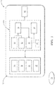
Figure 1 is a schematic block diagram of the side collision risk estimation system for a host vehicle according to one embodiment of the invention. -
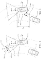
Figure 2 is schematic view of a target vehicle succeeding the host vehicle in the other side of a road line adjacent to the host vehicle, wherein the system offigure 1 is operating a first step for estimating a side collision risk between the host vehicle and the target vehicle. -
Figure 3 is a schematic view similar tofigure 2 wherein the system offigure 1 is operating another step for estimating the side collision risk between the host vehicle and the target vehicle. -
Figure 4 is a schematic view similar tofigure 2 wherein the system offigure 1 is operating few other steps for estimating the side collision risk between the host vehicle and the target vehicle. -
Figure 5 is a schematic view of the host vehicle travelling in its road lane wherein the system offigure 1 is operating some steps for estimating the side collision risk between the host vehicle and the target vehicle. -
Figure 6 is a schematic view similar wherein the system offigure 1 is operating a final step for estimating the side collision risk between the host vehicle and the target vehicle. -
Figure 7 is a flow chart of a method to operate the side collision risk estimation system according to one embodiment of the invention. - According to
figure 1 , a side collisionrisk estimation system 10 for ahost vehicle 12 is shown. The side collisionrisk estimation system 10 is configured to evaluate a side collision risk between thehost vehicle 12 and atarget vehicle 14 succeeding thehost vehicle 12 in the other side of the road line adjacent to thehost vehicle 12. According to the description, the adjacent road line is the road line that separates the lane of thetarget vehicle 14 to thehost vehicle 12. - The
system 10 comprises aspeed sensor 16 configured to capture the current speed Vhv of thehost vehicle 12, a road linemarkers detector unit 18 configured to capture road line markers on the path of thehost vehicle 12; amovement sensor unit 20 configured to capture the direction of thehost vehicle 12; and anobject detector unit 22 configured to detect atarget vehicle 14 in the neighboring of thehost vehicle 12. - More particularly, the road line
markers detector unit 18 may comprise a front vision detector and a rear vision detector such that thesystem 10 may evaluate the heading of the adjacent road line ahead thehost vehicle 12 and also the heading of the adjacent road line behind thehost vehicle 12. In other words, thesystem 10 may estimate or predict the heading of the adjacent road line ahead thehost vehicle 12 and also the heading of the adjacent road line behind thehost vehicle 12. - According to the invention, it is assumed that the adjacent road line markers arranged on the side of the host vehicle and the adjacent road line markers arranged behind the
host vehicle 12, i.e. behind the detection zone of the front vision detector, are a symmetrical expansion around the origin point of the adjacent road line markers ahead thehost vehicle 12. More precisely, the symmetrical expansion is an axial symmetry around the axis orthogonal to the tangent line of the curved road line at the origin point of detection. - Accordingly, when the
target vehicle 14 is in the rear neighboring of thehost vehicle 12, according to the invention, it may be considered that the adjacent road line markers ahead thetarget vehicle 14 are a symmetrical expansion around the origin point of the detected adjacent road line markers ahead thehost vehicle 12, such that thesystem 10 may comprise only one front vision detector, as a single front camera arranged on the front windshield of thehost vehicle 12, or elsewhere, that only captures the front road line markers. - Accordingly, the
system 10 comprises acontroller 24, or a processor, configured to estimate the heading of the road ahead thehost vehicle 12 from the adjacent road line markers ahead thehost vehicle 12 and also to estimate the heading of the road ahead thetarget vehicle 14 from the adjacent road line markers ahead thehost vehicle 12. - More particularly, the
movement sensor unit 20 of thehost vehicle 12 may be a two dimensions or three dimensions accelerometer, or alternatively a gyroscope, that is able to sense the direction of thehost vehicle 12. Those particular solutions provide faster and more accurate movement information than other means such as navigation system, steering wheel inclination sensor or other sensor coupled with mechanical part of thehost vehicle 12. - More particularly, the
object detector unit 22 may be a camera, a radar sensor or a Lidar sensor. Preferably, theobject detector unit 22 may comprise two rear corner side radar sensors or rear side Lidar sensors arranged on the right and on the left side rear corner of thehost vehicle 12 such that atarget vehicle 14 approaching thehost vehicle 12 and traveling toward thehost vehicle 12, in the same direction than thehost vehicle 12, and in the other side of a road line adjacent to thehost vehicle 12 may be easily detected, located and speed evaluated. A 90° field of view for each rear corner side radar may be enough to cover the desired rear side portion of thehost vehicle 12. - According to the invention, the
system 10 comprises thecontroller 24 in communication with thespeed sensor 16, the road linemarkers detector unit 18, themovement sensor unit 20, and theobject detector unit 22. - The
controller 24 comprises a heading of a roadline estimation block 26, such that by means of the road linemarkers detector unit 18, thecontroller 24 is configured to estimate the heading of the adjacent road line ahead thehost vehicle 12 and extrapolate the heading of the adjacent road line ahead thehost vehicle 12 to estimate the heading of the adjacent road line ahead thetarget vehicle 14. - The
controller 24 comprises a heading of avehicle estimation block 28, such that by means of themovement sensor unit 20 of thehost vehicle 12, thecontroller 24 is able to estimate a heading of thehost vehicle 12. In addition, by means of theobject detector unit 22, the heading of avehicle estimation block 28 of thecontroller 24 is configured to estimate the relative heading of thetarget vehicle 14 to thehost vehicle 12. - For more accurate prediction of the path of the
host vehicle 12, thecontroller 24 comprises a compensated heading ofvehicle estimation block 30 configured to calculate a compensated heading of thehost vehicle 12 by subtracting the estimated heading of the adjacent road line ahead thehost vehicle 12 to the estimated heading of thehost vehicle 12. - To predict a deviation of the trajectory of the
host vehicle 12 inside the road boundaries, i.e. the road line markers, thecontroller 24 comprises a vehicle lateral change position block 32 configured to calculate a predicted lateral change position of thehost vehicle 12 over the time relative to the current position of thehost vehicle 12 by combining the current speed Vhv of thehost vehicle 12, and the compensated heading of thehost vehicle 12. - The usage of the compensated heading of the
host vehicle 12 provides a great accuracy on estimation of the particular timing from when thehost vehicle 12 may leave its lane by crossing the adjacent road line in a curved road such that side collision risk estimation with thetarget vehicle 14 increased. - About the
target vehicle 14, by means of theobject detector unit 22 of thehost vehicle 12, the heading of a vehicle estimation block of thecontroller 24 is configured to estimate a relative heading of thetarget vehicle 14 to thehost vehicle 12. By means of theobject detector unit 22 of thehost vehicle 12, thecontroller 24 is also configured to estimate the current speed of thetarget vehicle 14. Thecontroller 24 comprises a lateraldistance estimation block 34 such that by means of theobject detector unit 22 of thehost vehicle 12, thecontroller 24 is configured to estimate the current lateral distance between thehost vehicle 12 and thetarget vehicle 14. The determination or estimation of the cited parameters of thetarget vehicle 14 relative to thehost vehicle 12 are necessary to monitor the behavior of thetarget vehicle 14 relative to the behavior of thehost vehicle 12. - According to the invention, for more accurate prediction of the path of the
target vehicle 14, the compensated heading ofvehicle estimation block 30 of thecontroller 24 is configured to calculate a compensated relative heading of thetarget vehicle 14 by subtracting the estimated heading of the adjacent road line ahead thetarget vehicle 14 to the estimated relative heading of atarget vehicle 14. - To predict a deviation of the trajectory of the
target vehicle 14 inside its road boundaries, i.e. its road line markers, the vehicle lateral change position block 32 of thecontroller 24 is configured to calculate a predicted lateral change position of thetarget vehicle 14 over the time relative to the current position of thetarget vehicle 14 by combining the current speed Vtv of thetarget vehicle 14, and the compensated relative heading of thetarget vehicle 14. - The usage of the compensated relative heading of the
target vehicle 14 provides a great accuracy on estimation of the particular timing from when thetarget vehicle 14 may leave its lane by crossing the adjacent road line in a curved road such that side collision risk estimation with thehost 12 vehicle increased. - To predict a side collision between the
target vehicle 14 and thehost vehicle 12, i.e. a zero lateral distance between both vehicles, the lateraldistance estimation block 34 of thecontroller 24 is configured to calculate the predicted lateral distance over the time between thehost vehicle 12 and thetarget vehicle 14 by combining the current lateral distance with the predicted lateral change position of thehost vehicle 12 over the time, and with the predicted lateral change position of thetarget vehicle 14 over the time. - Thus, from the predicted lateral distance over the time between the
host vehicle 12 and thetarget vehicle 14, i.e. the time to collision between thehost vehicle 12 and thetarget vehicle 14, thecontroller 24 is configured to evaluate side collision risk over the time. Thecontroller 24 comprises a side collisionrisk estimation block 36 configured to assess the risk of collision and to trigger a side collision warning and some advanced driver-assistance systems (ADAS) if some predetermined threshold(s) is(are) satisfied. Predetermined threshold such as time to collision threshold may be dependent on reaction time of ADAS system, or expected human reaction time as manual vehicle braking reaction time that may reduce collision risk. - According to
figures 2, 3 ,4, 5 and6 , the operation of the side collision risk estimation system of the host vehicle is shown. - According to
figure 2 , a longitudinal axis Lhv of the host vehicle is defined, said host vehicle longitudinal axis Lhv corresponding of the longitudinal axis Lhv of thehost vehicle 12, i.e. the axis according to which thehost vehicle 12 extends from the rear to the front and globally parallel to a flat road on which thehost vehicle 12 is travelling. A transversal axis Thv of thehost vehicle 12 is also defined, said host vehicle transversal axis Thv being orthogonal to the host vehicle longitudinal axis Lhv and also globally parallel to the flat road on which thehost vehicle 12 is travelling. The host vehicle transversal axis Thv is the axis according to which thehost vehicle 12 extends from the left to the right. - According to
figure 2 , thetarget vehicle 14 succeeds thehost vehicle 12 in the other side of theroad line 38 adjacent to thehost vehicle 12. The road linemarkers detector unit 18, i.e. the front camera arranged on the front windshield of thehost vehicle 12, is capturing images of theroad 40 ahead thehost vehicle 12. More particularly, the front camera is capturing images of the adjacentroad line markers host vehicle 12 such that thecontroller 24 is able to calculate the heading ϕrh of theadjacent road line 38a ahead thehost vehicle 12. - Accordingly, the heading ϕrh of the
adjacent road line 38a ahead thehost vehicle 12 detected by the front camera, i.e. the angle ϕrh of the adjacent road line relative to the host vehicle longitudinal axis Lhv, is evaluated as a third degree polynomial such that the heading ϕrh of theadjacent road line 38a ahead thehost vehicle 12 at a distance dxh from thehost vehicle 12 can be determined by equation 1:
line estimation block 26 of thecontroller 24. - According to
figure 3 , the exact similar situation offigure 2 is shown. According tofigure 3 , the adjacentroad line markers target vehicle 14 are a symmetrical expansion around the origin point O of the detected adjacentroad line markers host vehicle 12. In other words, the adjacentroad line markers target vehicle 14 are the symmetries of theroad line markers host vehicle 12 according to an axial symmetry around the axis orthogonal to the tangent line of the curved road line at the origin point of detection of theroad line markers host vehicle 12. - As it is assumed that the adjacent
road line markers target vehicle 14 are a symmetrical expansion around the origin point O of the detection of the adjacentroad line markers host vehicle 12, the heading ϕrt of theadjacent road line 38b ahead thetarget vehicle 14, at a distance dxt from the origin point O, i.e. the angle ϕrt of theadjacent road line 38b relative to the host vehicle longitudinal axis Lhv ahead thetarget vehicle 14, at a distance dxt from the origin point O, is evaluated from the equation 2 as the same third degree polynomial of equation 1 such that:
- According to
figure 4 , thetarget vehicle 14 succeeds thehost vehicle 12 in the other side of theroad line 38 adjacent to thehost vehicle 12. Theobject detector unit 22, i.e. the rear left corner side radar of thehost vehicle 12, is detecting thetarget vehicle 14. Aghost target vehicle 15 is shown at a predicted position of thetarget vehicle 14 at a preview timing tpreview following the current position of thetarget vehicle 14. - According to
figure 4 , a longitudinal axis Ltv of thetarget vehicle 14 is defined, said target vehicle longitudinal axis Ltv corresponding of the longitudinal axis Ltv of thetarget vehicle 14, i.e. the axis according to which thetarget vehicle 14 extends from the rear to the front and globally parallel to a flat road on which thetarget vehicle 14 is travelling. A transversal axis Ttv of thetarget vehicle 14 is also defined, said target vehicle transversal axis Ttv being orthogonal to the target vehicle longitudinal axis Ltv and also globally parallel to the flat road on which thetarget vehicle 14 is travelling. The target vehicle transversal axis Ttv is the axis according to which thetarget vehicle 14 extends from the left to the right. - According to
figure 4 , by means of the rear corner side radar of thehost vehicle 12, thehost vehicle 12 is estimated the current speed Vtv of thetarget vehicle 14, the current distance dht between thehost vehicle 12 and thetarget vehicle 14, and the relative heading αtv of thetarget vehicle 14 to thehost vehicle 12, i.e. relative to the longitudinal axis Lhv of thehost vehicle 12. - From the current distance dht between the
host vehicle 12 and thetarget vehicle 14, thesystem 10 is able to determine the current distance dlong between the origin point O and thetarget vehicle 14. From said current distance dlong between the origin point O and thetarget vehicle 14, and from equation 2, the predicted heading ϕrt of theadjacent road line 38b at thetarget vehicle 14 is evaluated from equation 3 such that:
- From equation 3, the current compensated heading αtv_comp of the
target vehicle 14 is evaluated by subtracting the estimated heading ϕrt(dlong) of theadjacent road line 38b at thetarget vehicle 14 to the estimated relative heading αtv of thetarget vehicle 14, as equation 4:
- From equation 4, the predicted lateral change position dlat_t(t) of the
target vehicle 14 over the time relative to the current position of thetarget vehicle 14 is evaluated. In other words, the estimated lateral position deviation of thetarget vehicle 14 over the time according to the current transversal axis Ttv of the target vehicle14 is evaluated. The predicted lateral change position dlat_t(t) of thetarget vehicle 14 over the time is calculated by combining the current speed Vtv of thetarget vehicle 14 and the compensated relative heading αtv_comp of thetarget vehicle 14, as equation 5:
- According to the example of
figure 4 , at the preview timing tpreview, the predicted lateral change position dlat_t(tpreview) between theghost target vehicle 15 position and thetarget vehicle 14 at the current position is estimated from equation 6 as being:
- According to
figure 5 , thehost vehicle 12 traveling in its lane is shown. Aghost host vehicle 13 is shown at a predicted position of thehost vehicle 12 at the preview time tpreview following the current position of thehost vehicle 12. - According to
figure 5 , the predicted lateral change position dlat_h(t) of thehost vehicle 12 over the time relative to the current position of thehost vehicle 12 is evaluated. In other words, thecontroller 24 is configured to calculate the estimated lateral position deviation of thehost vehicle 12 over the time according to the current transversal axis Thv of the host vehicle12. - According to one embodiment, the predicted lateral change position dlat_h(t) of the
host vehicle 12 over the time is then calculated using a constant yaw rate model to calculate the lateral movement of thehost vehicle 12. Accordingly, the calculation is done iteratively and the desired predetermined time, i.e. the preview time tpreview, is divided into segments equaling the length of sampling interval of the side collision risk estimation system. In the context of the invention, the length of sampling interval is the time duration between two samplings. In other words, the calculation is done according to a sampling acquisition time of themovement sensor unit 20, and of the road linemarkers detector unit 18 by thecontroller 24 of the side collisionrisk estimation system 10. - Accordingly, by means of the
movement sensor unit 20, the heading αhv of thehost vehicle 12 is evaluated over the time t by equation 7:
- Accordingly, the heading αhv of the
host vehicle 12 is evaluated over the preview time tpreview by equation 8: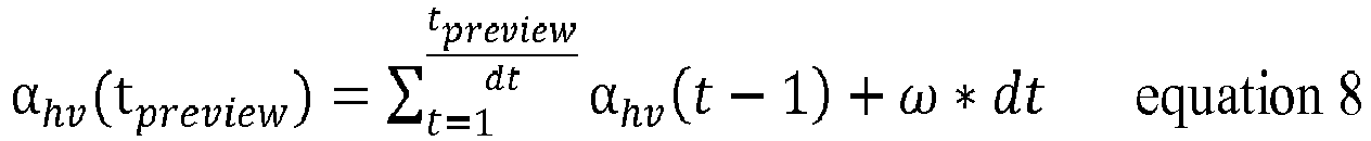
movement sensor unit 20. - According to
figure 5 , the predicted heading ϕrh of the adjacent road line ahead thehost vehicle 12 is sampled by thesystem 10, such that the plurality of adjacent road lines markers captured by the front vision detector of thehost vehicle 12 are sampled into a plurality of successive single predicted heading samples ϕrh_1, ϕrh_2,... ϕrh_tpreview/dt of theadjacent road line 38a ahead the current position of thehost vehicle 12. - The predicted heading ϕrh of the
adjacent road line 38a that will be reached by the host vehicle over the time, is identified as being the heading of theadjacent road line 38a at the distance dxh from thehost vehicle 12 given by the equation 9:
- The predicted heading sample ϕrh_tpreview/dt of the
adjacent road line 38a that will be reached by thehost vehicle 12 at the predetermined time, i.e. at the preview time tpreview, is identified as being the heading of theadjacent road line 38a at the distance dxh(tpreview) from thehost vehicle 12 given by the equation 10: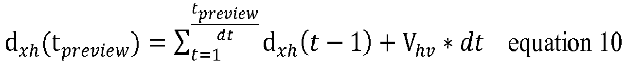
- The heading ϕrh of the
adjacent road line 38a at thehost vehicle 12 at a time moment relative to its current position is evaluated at the distance reached by thehost vehicle 12 at the time moment relative to its current position from equation 11:
adjacent road line 38a ahead the current position of thehost vehicle 12. - From equation 11, the compensated heading αhv_comp(t) of the
host vehicle 12 over the time t is evaluated by subtracting the estimated heading ϕrh(dxh(t)) of theadjacent road line 38a ahead thehost vehicle 12 to the estimated heading αth(t) of thehost vehicle 12 over the time, as equation 12:
- From
equation 12, the predicted lateral change position dlat_h(t) of thehost vehicle 12 over the time relative to the current position of thehost vehicle 12 is evaluated. In other words, the estimated lateral position deviation of thehost vehicle 12 over the time according to the current transversal axis Thv of the host vehicle12 is evaluated. The predicted lateral change position dlat_h(t) of thehost vehicle 12 over the time t is calculated by combining the current speed Vhv of thehost vehicle 12 and the compensated heading αhv_comp(t) of thehost vehicle 12, as equation 13:
- According to the example of
figure 5 , at the preview timing tpreview, the predicted lateral change position dlat_h(tpreview) between theghost host vehicle 13 position and thehost vehicle 12 at the current position, is estimated fromequation 14 as being:
- According to
figure 6 , thetarget vehicle 14 at a current position succeeding thehost vehicle 12 at a current position in the other side of theroad line 38 adjacent to thehost vehicle 12 is shown. Theghost target vehicle 15 at the positon at the preview time tpreview and theghost host vehicle 13 at the same preview time tpreview are shown. By the means of the corner side radar, preferably a left corner side radar or a right corner side radar, or a combination of both, thecontroller 24 of the side collisionrisk estimation system 10 is configured to evaluate the current lateral distance dlat_cvh between thehost vehicle 12 and thetarget vehicle 14. Generally, said current lateral distance dlat_cvh is representative of the shortest measured distance from thehost vehicle 12 to thetarget vehicle 12 while thetarget vehicle 12 is travelling in the other side of theroad line 38 adjacent to thehost vehicle 12. From the measured current lateral distance dlat_cvh between thehost vehicle 12 and thetarget vehicle 14, thesystem 10 is configured to calculate the predicted lateral distance Pdlat_vh over the time t between thehost vehicle 12 and thetarget vehicle 14 by combining the current lateral distance dlat_cvh with the predicted lateral change position dlat_h(t) of thehost vehicle 12 over the time t, and with the predicted lateral change position dlat_t(t) of thetarget vehicle 14 over the time using equation 15:
- The predicted lateral change position dlat_h(t) of the
host vehicle 12 over the time t, and the predicted lateral change position dlat_t(t) of thetarget vehicle 14 over the time may be a positive value or a negative value as dependent on the transversal direction of the lateral change position of thehost vehicle 12 and of thetarget vehicle 14. - According to the example of
figure 6 , at the preview timing tpreview, the predicted lateral distance Pdlat_vh(tpreview) between thehost vehicle 12 and thetarget vehicle 14 is estimated fromequation 16 as being:
- The collision risk estimation may be set up by setting up a predicted safety lateral distance Pdlat_vh threshold in combination to a the time to collision threshold from which a driver of the host vehicle could not be generally able to avoid the collision such that ADAS system is taking over the control of the host vehicle to limit the collision risk.
- According to
figure 7 , following the description of the previous figures, amethod 100 of operating the side collisionrisk estimation system 10 to estimate a side collision risk with atarget vehicle 14 succeeding thehost vehicle 12 in the other side of aroad line 38 adjacent to thehost vehicle 12 comprises some steps for estimating predicted path over the time of thehost vehicle 12. - The first steps comprises a step of estimating 110 the current speed Vhv of the
host vehicle 12, a step of estimating 120 the heading ϕrh of the adjacent road line ahead thehost vehicle 12; and a step of estimating 130 the heading αhv of thehost vehicle 12. For an optimum accuracy, the estimation of the heading αhv of thehost vehicle 12 has to be correlated with the heading of the road ahead thehost vehicle 12. Thus, the method comprises as step of calculating 140 a compensated heading αhv_comp of thehost vehicle 12 by combining the estimated heading ϕrh of the adjacent road line ahead thehost vehicle 12 with the estimated heading αhv of ahost vehicle 12. More particularly, the step of calculating 14 the compensated heading αhv_comp of thehost vehicle 12 is a step of subtracting the estimated heading ϕrh of the adjacent road line ahead thehost vehicle 12 to the estimated heading αhv of ahost vehicle 12. - Starting from the compensated heading αhv_comp of the
host vehicle 12, a predicted lateral deviation relative to the current position of thehost vehicle 12 can be calculated. Thus, the method comprises a step of calculating 150 the predicted lateral change position dlat_h(t) of thehost vehicle 12 over the time t relative to the current position of thehost vehicle 12 by combining the current speed Vhv of thehost vehicle 12, and the compensated heading αhv_comp of thehost vehicle 12. The predicted lateral change position dlat_h(t) of thehost vehicle 12 over the time relative to the current position of thehost vehicle 12 is taking into account the lateral change of thehost vehicle 12 regarding the temporal change direction of thehost vehicle 12 provided by itsmovement sensor unit 20 and the heading ϕrh of theadjacent road line 38a ahead thehost vehicle 12, such that it will be possible to predict that thehost vehicle 12 may leave its road lane as crossing the adjacentroad line markers - The
method 100 comprises steps relative to thetarget vehicle 14 in order to evaluate the collision risk between thehost vehicle 12 and thetarget vehicle 14. At first, the method comprises some steps for estimating predicted path over the time of thetarget vehicle 14. - The first steps comprises a step of estimating 210 the current speed Vtv of the
target vehicle 14; a step of estimating 220 the heading ϕrt of theadjacent road line 38b ahead thetarget vehicle 14; and a step of estimating 230 the relative heading αtv of thetarget vehicle 14 to thehost vehicle 12. - For an optimum accuracy, the estimation of the relative heading αtv of the
target vehicle 14 has to be correlated with the heading ϕrt of adjacent the road line ahead thetarget vehicle 14. Thus, the method comprises as step of calculating 240 a compensated relative heading αtv_comp of thetarget vehicle 14 by subtracting the estimated heading ϕrt of theadjacent road line 38b ahead thetarget vehicle 14 to the estimated relative heading αtv of thetarget vehicle 14. - Starting from the compensated relative heading αtv_comp of the
target vehicle 14, a predicted lateral deviation of thetarget vehicle 14 relative the current position of thetarget vehicle 14 can be calculated. Thus, the method comprises a step of calculating 250 the predicted lateral change position dlat_t(t) of thetarget vehicle 14 over the time relative to the current position of thetarget vehicle 14 by combining the current speed Vtv of thetarget vehicle 14, and the compensated relative heading αtv_comp of thetarget vehicle 14. - In order to predict a time to collision parameter, i.e. a risk of collision over the time, the method comprises a step of estimating 310 the current lateral distance between the
host vehicle 12 and thetarget vehicle 14. Such estimation is used as a starting point in time to evaluate a predicted lateral distance over the time between thehost vehicle 12 and thetarget vehicle 14. Thus, the method comprises a step of calculating 320 a predicted lateral distance over the time between thehost vehicle 12 and thetarget vehicle 14 by combining the current lateral distance with the predicted lateral change position dlat_h(t) of thehost vehicle 12 over the time, and with the predicted lateral change position dlat_t(t) of thetarget vehicle 14 over the time. More particularly, the step of calculating 320 the predicted lateral distance over the time between thehost vehicle 12 and thetarget vehicle 14 comprises a step of adding or subtracting, depending on the transversal direction of the lateral change position of thehost vehicle 12 and of thetarget vehicle 14, the predicted lateral change position dlat_h(t) of thehost vehicle 12 over the time, and the predicted lateral change position dlat_t(t) of thetarget vehicle 14 over the time, to the current lateral distance between thehost vehicle 12 and thetarget vehicle 14. - Finally, the
method 100 comprises a step of evaluating 330 a side collision risk over the time from the predicted lateral distance between thehost vehicle 12 and thetarget vehicle 14. The evaluation generally comprises one or more predetermined threshold(s). A predetermined threshold such as time to collision threshold relative to reaction time of ADAS system, or relative to expected human reaction time as manual vehicle braking reaction time that may be used for that evaluation step. - According to the assumption that the adjacent road line markers arranged on the side of the host vehicle and the adjacent road line markers road arranged behind the
host vehicle 12, i.e. behind the detection zone of the front vision detector, are a symmetrical expansion around the origin point O of detection of the adjacentroad line markers host vehicle 12, the step of estimating 220 the heading ϕrt of theadjacent road line 38b ahead thetarget vehicle 14 can preliminary comprises a step of assigning 120 to the adjacentroad line markers road line markers host vehicle 12. Thus, the step of estimating 220 the heading ϕrt of theadjacent road line 38b ahead thetarget vehicle 14 can comprise a step of detectingroad line markers host vehicle 12. - Referring again to
Fig. 1 , thesystem 10 includes a first device that includes one or more instances of thecontroller 24, amemory 25, and one or more instances of a program stored in thememory 25. The one or more programs include instructions for performing themethod 100. - The
system 10 also includes or consists of a non-transitory computer-readable storage medium comprising one or more programs for execution by one ormore controller 24 or processor of the first device, the one or more programs including instructions which, when executed by the one ormore controller 24 or processor, cause the first device to perform themethod 100.
Claims (10)
- Side collision risk estimation system (10) for a host vehicle (12) comprises
a speed sensor (16) configured to capture the current speed (Vhv) of the host vehicle (12);
a road line markers detector unit (18) configured to capture road line markers (42, 44) on the path of the host vehicle (12);
a movement sensor unit (20) configured to capture the direction of the host vehicle (12);
an object detector unit (22) configured to detect a target vehicle (14);
a controller (24) in communication with the speed sensor (16), the road line markers detector unit (18), the movement sensor unit (20), and the object detector unit (22), said controller (24) being configured to:estimate the current speed (Vhv) of the host vehicle (12) by means of the speed sensor (16);estimate a heading (ϕrh) of the adjacent road line (38a) ahead the host vehicle (12) by means of the road line markers detector unit (18);estimate a heading (αhv) of the host vehicle (12) by means of the movement sensor unit (20);calculate a compensated heading (αhv_comp) of the host vehicle (12) by subtracting the estimated heading (ϕrh) of the adjacent road line (38a) ahead the host vehicle (12) to the estimated heading (αhv) of the host vehicle (12);calculate a predicted lateral change position (dlat_h(t)) of the host vehicle (12) over the time relative to the current position of the host vehicle (12) by combining the current speed (Vhv) of the host vehicle (12), and the compensated heading (αhv_comp) of the host vehicle (12);estimate a relative heading (αtv) of the target vehicle (14) to the host vehicle (12), estimate the current speed (Vtv) of the target vehicle (14) and estimate the current lateral distance between the host vehicle (12) and the target vehicle (14) by means of the object detector unit (22);estimate the heading (ϕrt) of the adjacent road line (38b) ahead the target vehicle (14) by means of the road line markers detector unit (18);calculate a compensated relative heading (αtv_comp) of the target vehicle (14) by subtracting the estimated heading (ϕrt) of the adjacent road line (38b) ahead the target vehicle (14) to the estimated relative heading (αtv) of the target vehicle (14);calculate a predicted lateral change position (dlat_t(t)) of the target vehicle (14) over the time relative to the current position of the target vehicle (14) by combining the current speed (Vtv) of the target vehicle (14), and the compensated relative heading (αtv_comp) of the target vehicle (14);calculate the predicted lateral distance over the time between the host vehicle (12) and the target vehicle (14) by combining the current lateral distance with the predicted lateral change position (dlat_h(t)) of the host vehicle (12) over the time, and with the predicted lateral change position (dlat_t(t)) of the target vehicle (14) over the time;evaluate side collision risk over the time from the predicted lateral distance between the host vehicle (12) and the target vehicle (14). - System (10) of claim 1 wherein the controller (24) is configured to estimate the heading (ϕrt) of the adjacent road line (38b) ahead the target vehicle (14) by assigning to the adjacent road line markers (46, 48) ahead the target vehicle (14), a symmetrical expansion around the origin point (O) of detection of the adjacent road line markers (42, 44) ahead the host vehicle (12).
- System (10) of claim 2 wherein the road line markers detector unit (18) includes a single vision detector configured to detect road line markers (42, 44) ahead the host vehicle (12).
- Host vehicle (12) comprises the system (10) of any one of the preceding claims.
- Host vehicle (12) according to the preceding claim whereinthe road line markers detector unit (18) comprises at least one front camera configured to capture the front road line markers ahead the host vehicle (12);the movement sensor unit (20) comprises a 2D accelerometer or a gyroscope configured to capture the path direction of the host vehicle (12);the object detector unit (22) comprises at least one rear radar sensor or Lidar sensor, preferably arranged at a corner side of the host vehicle (12), said object detector unit (22) being configured to detect object at a side rear location of the host vehicle (12).
- Method (100) of operating the side collision risk estimation system (10) of any one of the claims 1 to 3 to estimate a side collision risk with a target vehicle (14) succeeding the host vehicle (12) in the other side of a road line (38) adjacent to the host vehicle (12), said method comprising the steps of:estimating (110) the current speed (Vhv) of the host vehicle (12);estimating (120) the heading (ϕrh) of the adjacent road line (38a) ahead the host vehicle (12);estimating (130) the heading (αhv) of the host vehicle (12);calculating (140) a compensated heading (αhv_comp) of the host vehicle (12) by subtracting the estimated heading (ϕrh) of the adjacent road line (38a) ahead the host vehicle (12) to the estimated heading (αhv) of a host vehicle (12);calculating (150) the predicted lateral change position (dlat_h(t)) of the host vehicle (12) over the time relative to the current position of the host vehicle (12) by combining the current speed (Vhv) of the host vehicle (12), and the compensated heading (αhv_comp) of the host vehicle (12);estimating (210) the current speed (Vtv) of the target vehicle (14);estimating (220) the heading (ϕrt) of the adjacent road line (38b) ahead the target vehicle (14);estimating (230) the relative heading (αtv) of the target vehicle (14) to the host vehicle (12);calculating (240) a compensated relative heading (αtv_comp) of the target vehicle (14) by subtracting the estimated heading (ϕrt) of the adjacent road line (38b) ahead the target vehicle (14) to the estimated relative heading (αtv) of the target vehicle (14);calculating (250) the predicted lateral change position (dlat_t(t)) of the target vehicle (14) over the time relative to the current position of the target vehicle by combining the current speed (Vtv) of the target vehicle (14), and the compensated relative heading (αtv_comp) of the target vehicle (14);estimating (310) the current lateral distance between the host vehicle (12) and the target vehicle (14);calculating (320) a predicted lateral distance over the time between the host vehicle (12) and the target vehicle (14) by combining the current lateral distance with the predicted lateral change position (dlat_h(t)) of the host vehicle (12) over the time, and with the predicted lateral change (dlat_t(t)) position of the target vehicle (14) over the time;evaluating (330) side collision risk over the time from the predicted lateral distance between the host vehicle (12) and the target vehicle (14).
- Method (100) according to the preceding claim wherein the step of estimating (220) the heading (ϕrt) of the adjacent road line (38b) ahead the target vehicle (14) further preliminary comprises the step of:
assigning (120) to the adjacent road line markers (46, 48) ahead the target vehicle (14) a symmetrical expansion around the origin point (O) of detection of the adjacent road line markers (42, 44) ahead the host vehicle (12). - Method (100) according to claim 7 wherein the step of estimating (220) the heading (ϕrt) of the adjacent road line (38b) ahead the target vehicle (14) comprises a step of detecting road line markers (42, 44) only ahead the host vehicle (12).
- A first device comprising:one or more processors (24);memory (25); and one or more programs stored in memory (25), the one or more programs including instructions for performing the method of claims 6 to 8.
- A non-transitory computer-readable storage-medium (25) comprising one or more programs for execution by one or more processors (24) of a first device, the one or more programs including instructions which, when executed by the one or more processors (24), cause the first device to perform the method of claims 6 to 8.
Priority Applications (3)
| Application Number | Priority Date | Filing Date | Title |
|---|---|---|---|
| EP19160451.1A EP3705384B1 (en) | 2019-03-04 | 2019-03-04 | Side collision risk estimation system for a vehicle |
| CN202010123645.XA CN111645679B (en) | 2019-03-04 | 2020-02-27 | Side collision risk estimation system for vehicle |
| US16/807,513 US11498556B2 (en) | 2019-03-04 | 2020-03-03 | Side collision risk estimation system for a vehicle |
Applications Claiming Priority (1)
| Application Number | Priority Date | Filing Date | Title |
|---|---|---|---|
| EP19160451.1A EP3705384B1 (en) | 2019-03-04 | 2019-03-04 | Side collision risk estimation system for a vehicle |
Publications (2)
| Publication Number | Publication Date |
|---|---|
| EP3705384A1 true EP3705384A1 (en) | 2020-09-09 |
| EP3705384B1 EP3705384B1 (en) | 2021-12-22 |
Family
ID=65686714
Family Applications (1)
| Application Number | Title | Priority Date | Filing Date |
|---|---|---|---|
| EP19160451.1A Active EP3705384B1 (en) | 2019-03-04 | 2019-03-04 | Side collision risk estimation system for a vehicle |
Country Status (3)
| Country | Link |
|---|---|
| US (1) | US11498556B2 (en) |
| EP (1) | EP3705384B1 (en) |
| CN (1) | CN111645679B (en) |
Cited By (1)
| Publication number | Priority date | Publication date | Assignee | Title |
|---|---|---|---|---|
| CN112202890A (en) * | 2020-09-30 | 2021-01-08 | 腾讯科技(深圳)有限公司 | Early warning method and device for vehicle driving risk and computer equipment |
Families Citing this family (5)
| Publication number | Priority date | Publication date | Assignee | Title |
|---|---|---|---|---|
| CN112519797A (en) * | 2020-12-10 | 2021-03-19 | 广州小鹏自动驾驶科技有限公司 | Vehicle safety distance early warning method, early warning system, automobile and storage medium |
| CN113096441B (en) * | 2021-03-25 | 2022-08-05 | 北京星云互联科技有限公司 | Vehicle early warning method and device, vehicle and storage medium |
| CN115547099A (en) * | 2021-06-30 | 2022-12-30 | 中兴通讯股份有限公司 | Early warning method, electronic device and computer-readable storage medium |
| US11851052B2 (en) * | 2022-01-31 | 2023-12-26 | Ford Global Technologies, Llc | Vehicle path verification |
| DE102022204161A1 (en) * | 2022-04-28 | 2023-11-02 | Robert Bosch Gesellschaft mit beschränkter Haftung | Method for avoiding a collision of a vehicle |
Citations (4)
| Publication number | Priority date | Publication date | Assignee | Title |
|---|---|---|---|---|
| US20040167717A1 (en) * | 2001-05-17 | 2004-08-26 | Buchanan Alastair James | Sensing apparatus for vehicles |
| US8494716B1 (en) * | 2012-06-04 | 2013-07-23 | GM Global Technology Operations LLC | Lane keeping system using rear camera |
| US20170197549A1 (en) * | 2016-01-12 | 2017-07-13 | Toyota Motor Engineering & Manufacturing North America, Inc. | Apparatus and method for providing an extended forward collision warning |
| US20190004166A1 (en) * | 2017-06-29 | 2019-01-03 | Delphi Technologies, Llc | Method to determine the orientation of a target vehicle |
Family Cites Families (12)
| Publication number | Priority date | Publication date | Assignee | Title |
|---|---|---|---|---|
| EP2085279B1 (en) * | 2008-01-29 | 2011-05-25 | Ford Global Technologies, LLC | A system for collision course prediction |
| US8120476B2 (en) * | 2009-07-22 | 2012-02-21 | International Truck Intellectual Property Company, Llc | Digital camera rear-view system |
| US9963127B2 (en) * | 2010-01-15 | 2018-05-08 | Volvo Car Corporation | Collision mitigation system and method for braking a vehicle |
| CN106407893B (en) * | 2016-08-29 | 2019-11-22 | 东软集团股份有限公司 | A kind of method, apparatus and equipment detecting lane line |
| JP6515898B2 (en) * | 2016-09-29 | 2019-05-22 | トヨタ自動車株式会社 | Target lane relation recognition device |
| KR101977458B1 (en) * | 2017-03-06 | 2019-05-10 | 지엠 글로벌 테크놀러지 오퍼레이션스 엘엘씨 | Vehicle collision prediction algorithm using radar sensor and upa sensor |
| CN108569289A (en) * | 2017-05-19 | 2018-09-25 | 浙江工业职业技术学院 | A kind of trailer-mounted radar and its approach detection and target-recognition method |
| US10829120B2 (en) * | 2018-06-18 | 2020-11-10 | Valeo Schalter Und Sensoren Gmbh | Proactive safe driving for an automated vehicle |
| KR102496290B1 (en) * | 2018-07-06 | 2023-02-06 | 현대모비스 주식회사 | Apparatus and method for compensating heading angle |
| US10875531B2 (en) * | 2018-08-08 | 2020-12-29 | Ford Global Technologies, Llc | Vehicle lateral motion control |
| US10829113B2 (en) * | 2018-09-17 | 2020-11-10 | Ford Global Technologies, Llc | Vehicle collision avoidance |
| CN109583151B (en) * | 2019-02-20 | 2023-07-21 | 阿波罗智能技术(北京)有限公司 | Method and device for predicting running track of vehicle |
-
2019
- 2019-03-04 EP EP19160451.1A patent/EP3705384B1/en active Active
-
2020
- 2020-02-27 CN CN202010123645.XA patent/CN111645679B/en active Active
- 2020-03-03 US US16/807,513 patent/US11498556B2/en active Active
Patent Citations (4)
| Publication number | Priority date | Publication date | Assignee | Title |
|---|---|---|---|---|
| US20040167717A1 (en) * | 2001-05-17 | 2004-08-26 | Buchanan Alastair James | Sensing apparatus for vehicles |
| US8494716B1 (en) * | 2012-06-04 | 2013-07-23 | GM Global Technology Operations LLC | Lane keeping system using rear camera |
| US20170197549A1 (en) * | 2016-01-12 | 2017-07-13 | Toyota Motor Engineering & Manufacturing North America, Inc. | Apparatus and method for providing an extended forward collision warning |
| US20190004166A1 (en) * | 2017-06-29 | 2019-01-03 | Delphi Technologies, Llc | Method to determine the orientation of a target vehicle |
Cited By (2)
| Publication number | Priority date | Publication date | Assignee | Title |
|---|---|---|---|---|
| CN112202890A (en) * | 2020-09-30 | 2021-01-08 | 腾讯科技(深圳)有限公司 | Early warning method and device for vehicle driving risk and computer equipment |
| CN112202890B (en) * | 2020-09-30 | 2022-03-22 | 腾讯科技(深圳)有限公司 | Early warning method and device for vehicle driving risk and computer equipment |
Also Published As
| Publication number | Publication date |
|---|---|
| US20200282985A1 (en) | 2020-09-10 |
| CN111645679B (en) | 2023-06-27 |
| CN111645679A (en) | 2020-09-11 |
| EP3705384B1 (en) | 2021-12-22 |
| US11498556B2 (en) | 2022-11-15 |
Similar Documents
| Publication | Publication Date | Title |
|---|---|---|
| EP3705384B1 (en) | Side collision risk estimation system for a vehicle | |
| US10350999B2 (en) | Vehicle cruise control apparatus and vehicle cruise control method | |
| JP6005055B2 (en) | Method for continuously calculating, inspecting and / or adapting a parking trajectory in a vehicle parking assist system, a computer program and a parking assist system | |
| JP5281664B2 (en) | Lane departure warning device and lane departure warning system | |
| JP6363516B2 (en) | Vehicle travel control device | |
| CN107004367B (en) | Vehicle travel control device and travel control method | |
| US10339393B2 (en) | Demarcation line recognition apparatus | |
| EP3486132A1 (en) | Vehicle control device | |
| CN110998685B (en) | Travel obstacle detection device and vehicle navigation system | |
| CN109212572B (en) | Positioning drift detection method, device and equipment and computer readable storage medium | |
| US20120316723A1 (en) | method for determining at least one trafficable area in the surroundings of a motor vehicle | |
| US11238731B2 (en) | Method and device for detecting the passage of a motor vehicle through a road sign gantry | |
| JP2012089114A (en) | Obstacle recognition device | |
| KR101249366B1 (en) | Apparatus for detecting lane and control method of it | |
| US10878702B2 (en) | Driving support apparatus and driving support method | |
| JP7109661B2 (en) | A method for evaluating the influence of objects around the means of transportation on the driving operation of the means of transportation | |
| GB2486814A (en) | Method for assisting a driver of a motor vehicle | |
| CN113335311B (en) | Vehicle collision detection method and device, vehicle and storage medium | |
| US11087149B2 (en) | Object detection apparatus | |
| JP5103722B2 (en) | Stop vehicle discrimination device | |
| JP2015154337A (en) | Target range setting device and target range setting program | |
| JP6169270B2 (en) | Method and apparatus for identifying running state of external vehicle | |
| JP4976998B2 (en) | Vehicle travel safety device | |
| JP4768499B2 (en) | In-vehicle peripheral other vehicle detection device | |
| EP3020609B1 (en) | A vehicle safety system |
Legal Events
| Date | Code | Title | Description |
|---|---|---|---|
| PUAI | Public reference made under article 153(3) epc to a published international application that has entered the european phase |
Free format text: ORIGINAL CODE: 0009012 |
|
| STAA | Information on the status of an ep patent application or granted ep patent |
Free format text: STATUS: THE APPLICATION HAS BEEN PUBLISHED |
|
| AK | Designated contracting states |
Kind code of ref document: A1 Designated state(s): AL AT BE BG CH CY CZ DE DK EE ES FI FR GB GR HR HU IE IS IT LI LT LU LV MC MK MT NL NO PL PT RO RS SE SI SK SM TR |
|
| AX | Request for extension of the european patent |
Extension state: BA ME |
|
| STAA | Information on the status of an ep patent application or granted ep patent |
Free format text: STATUS: REQUEST FOR EXAMINATION WAS MADE |
|
| 17P | Request for examination filed |
Effective date: 20210302 |
|
| RBV | Designated contracting states (corrected) |
Designated state(s): AL AT BE BG CH CY CZ DE DK EE ES FI FR GB GR HR HU IE IS IT LI LT LU LV MC MK MT NL NO PL PT RO RS SE SI SK SM TR |
|
| GRAP | Despatch of communication of intention to grant a patent |
Free format text: ORIGINAL CODE: EPIDOSNIGR1 |
|
| STAA | Information on the status of an ep patent application or granted ep patent |
Free format text: STATUS: GRANT OF PATENT IS INTENDED |
|
| INTG | Intention to grant announced |
Effective date: 20210709 |
|
| GRAS | Grant fee paid |
Free format text: ORIGINAL CODE: EPIDOSNIGR3 |
|
| GRAA | (expected) grant |
Free format text: ORIGINAL CODE: 0009210 |
|
| STAA | Information on the status of an ep patent application or granted ep patent |
Free format text: STATUS: THE PATENT HAS BEEN GRANTED |
|
| AK | Designated contracting states |
Kind code of ref document: B1 Designated state(s): AL AT BE BG CH CY CZ DE DK EE ES FI FR GB GR HR HU IE IS IT LI LT LU LV MC MK MT NL NO PL PT RO RS SE SI SK SM TR |
|
| REG | Reference to a national code |
Ref country code: GB Ref legal event code: FG4D |
|
| REG | Reference to a national code |
Ref country code: CH Ref legal event code: EP |
|
| REG | Reference to a national code |
Ref country code: DE Ref legal event code: R096 Ref document number: 602019010176 Country of ref document: DE |
|
| REG | Reference to a national code |
Ref country code: AT Ref legal event code: REF Ref document number: 1456889 Country of ref document: AT Kind code of ref document: T Effective date: 20220115 |
|
| REG | Reference to a national code |
Ref country code: IE Ref legal event code: FG4D |
|
| REG | Reference to a national code |
Ref country code: LT Ref legal event code: MG9D |
|
| PG25 | Lapsed in a contracting state [announced via postgrant information from national office to epo] |
Ref country code: RS Free format text: LAPSE BECAUSE OF FAILURE TO SUBMIT A TRANSLATION OF THE DESCRIPTION OR TO PAY THE FEE WITHIN THE PRESCRIBED TIME-LIMIT Effective date: 20211222 Ref country code: LT Free format text: LAPSE BECAUSE OF FAILURE TO SUBMIT A TRANSLATION OF THE DESCRIPTION OR TO PAY THE FEE WITHIN THE PRESCRIBED TIME-LIMIT Effective date: 20211222 Ref country code: FI Free format text: LAPSE BECAUSE OF FAILURE TO SUBMIT A TRANSLATION OF THE DESCRIPTION OR TO PAY THE FEE WITHIN THE PRESCRIBED TIME-LIMIT Effective date: 20211222 Ref country code: BG Free format text: LAPSE BECAUSE OF FAILURE TO SUBMIT A TRANSLATION OF THE DESCRIPTION OR TO PAY THE FEE WITHIN THE PRESCRIBED TIME-LIMIT Effective date: 20220322 |
|
| REG | Reference to a national code |
Ref country code: NL Ref legal event code: MP Effective date: 20211222 |
|
| REG | Reference to a national code |
Ref country code: AT Ref legal event code: MK05 Ref document number: 1456889 Country of ref document: AT Kind code of ref document: T Effective date: 20211222 |
|
| PG25 | Lapsed in a contracting state [announced via postgrant information from national office to epo] |
Ref country code: SE Free format text: LAPSE BECAUSE OF FAILURE TO SUBMIT A TRANSLATION OF THE DESCRIPTION OR TO PAY THE FEE WITHIN THE PRESCRIBED TIME-LIMIT Effective date: 20211222 Ref country code: NO Free format text: LAPSE BECAUSE OF FAILURE TO SUBMIT A TRANSLATION OF THE DESCRIPTION OR TO PAY THE FEE WITHIN THE PRESCRIBED TIME-LIMIT Effective date: 20220322 Ref country code: LV Free format text: LAPSE BECAUSE OF FAILURE TO SUBMIT A TRANSLATION OF THE DESCRIPTION OR TO PAY THE FEE WITHIN THE PRESCRIBED TIME-LIMIT Effective date: 20211222 Ref country code: HR Free format text: LAPSE BECAUSE OF FAILURE TO SUBMIT A TRANSLATION OF THE DESCRIPTION OR TO PAY THE FEE WITHIN THE PRESCRIBED TIME-LIMIT Effective date: 20211222 Ref country code: GR Free format text: LAPSE BECAUSE OF FAILURE TO SUBMIT A TRANSLATION OF THE DESCRIPTION OR TO PAY THE FEE WITHIN THE PRESCRIBED TIME-LIMIT Effective date: 20220323 |
|
| PG25 | Lapsed in a contracting state [announced via postgrant information from national office to epo] |
Ref country code: NL Free format text: LAPSE BECAUSE OF FAILURE TO SUBMIT A TRANSLATION OF THE DESCRIPTION OR TO PAY THE FEE WITHIN THE PRESCRIBED TIME-LIMIT Effective date: 20211222 |
|
| PG25 | Lapsed in a contracting state [announced via postgrant information from national office to epo] |
Ref country code: SM Free format text: LAPSE BECAUSE OF FAILURE TO SUBMIT A TRANSLATION OF THE DESCRIPTION OR TO PAY THE FEE WITHIN THE PRESCRIBED TIME-LIMIT Effective date: 20211222 Ref country code: SK Free format text: LAPSE BECAUSE OF FAILURE TO SUBMIT A TRANSLATION OF THE DESCRIPTION OR TO PAY THE FEE WITHIN THE PRESCRIBED TIME-LIMIT Effective date: 20211222 Ref country code: RO Free format text: LAPSE BECAUSE OF FAILURE TO SUBMIT A TRANSLATION OF THE DESCRIPTION OR TO PAY THE FEE WITHIN THE PRESCRIBED TIME-LIMIT Effective date: 20211222 Ref country code: PT Free format text: LAPSE BECAUSE OF FAILURE TO SUBMIT A TRANSLATION OF THE DESCRIPTION OR TO PAY THE FEE WITHIN THE PRESCRIBED TIME-LIMIT Effective date: 20220422 Ref country code: ES Free format text: LAPSE BECAUSE OF FAILURE TO SUBMIT A TRANSLATION OF THE DESCRIPTION OR TO PAY THE FEE WITHIN THE PRESCRIBED TIME-LIMIT Effective date: 20211222 Ref country code: EE Free format text: LAPSE BECAUSE OF FAILURE TO SUBMIT A TRANSLATION OF THE DESCRIPTION OR TO PAY THE FEE WITHIN THE PRESCRIBED TIME-LIMIT Effective date: 20211222 Ref country code: CZ Free format text: LAPSE BECAUSE OF FAILURE TO SUBMIT A TRANSLATION OF THE DESCRIPTION OR TO PAY THE FEE WITHIN THE PRESCRIBED TIME-LIMIT Effective date: 20211222 |
|
| PG25 | Lapsed in a contracting state [announced via postgrant information from national office to epo] |
Ref country code: PL Free format text: LAPSE BECAUSE OF FAILURE TO SUBMIT A TRANSLATION OF THE DESCRIPTION OR TO PAY THE FEE WITHIN THE PRESCRIBED TIME-LIMIT Effective date: 20211222 Ref country code: AT Free format text: LAPSE BECAUSE OF FAILURE TO SUBMIT A TRANSLATION OF THE DESCRIPTION OR TO PAY THE FEE WITHIN THE PRESCRIBED TIME-LIMIT Effective date: 20211222 |
|
| REG | Reference to a national code |
Ref country code: DE Ref legal event code: R097 Ref document number: 602019010176 Country of ref document: DE |
|
| PG25 | Lapsed in a contracting state [announced via postgrant information from national office to epo] |
Ref country code: IS Free format text: LAPSE BECAUSE OF FAILURE TO SUBMIT A TRANSLATION OF THE DESCRIPTION OR TO PAY THE FEE WITHIN THE PRESCRIBED TIME-LIMIT Effective date: 20220422 |
|
| PLBE | No opposition filed within time limit |
Free format text: ORIGINAL CODE: 0009261 |
|
| STAA | Information on the status of an ep patent application or granted ep patent |
Free format text: STATUS: NO OPPOSITION FILED WITHIN TIME LIMIT |
|
| PG25 | Lapsed in a contracting state [announced via postgrant information from national office to epo] |
Ref country code: MC Free format text: LAPSE BECAUSE OF FAILURE TO SUBMIT A TRANSLATION OF THE DESCRIPTION OR TO PAY THE FEE WITHIN THE PRESCRIBED TIME-LIMIT Effective date: 20211222 Ref country code: DK Free format text: LAPSE BECAUSE OF FAILURE TO SUBMIT A TRANSLATION OF THE DESCRIPTION OR TO PAY THE FEE WITHIN THE PRESCRIBED TIME-LIMIT Effective date: 20211222 Ref country code: AL Free format text: LAPSE BECAUSE OF FAILURE TO SUBMIT A TRANSLATION OF THE DESCRIPTION OR TO PAY THE FEE WITHIN THE PRESCRIBED TIME-LIMIT Effective date: 20211222 |
|
| REG | Reference to a national code |
Ref country code: CH Ref legal event code: PL |
|
| 26N | No opposition filed |
Effective date: 20220923 |
|
| REG | Reference to a national code |
Ref country code: BE Ref legal event code: MM Effective date: 20220331 |
|
| PG25 | Lapsed in a contracting state [announced via postgrant information from national office to epo] |
Ref country code: LU Free format text: LAPSE BECAUSE OF NON-PAYMENT OF DUE FEES Effective date: 20220304 Ref country code: LI Free format text: LAPSE BECAUSE OF NON-PAYMENT OF DUE FEES Effective date: 20220331 Ref country code: IE Free format text: LAPSE BECAUSE OF NON-PAYMENT OF DUE FEES Effective date: 20220304 Ref country code: CH Free format text: LAPSE BECAUSE OF NON-PAYMENT OF DUE FEES Effective date: 20220331 |
|
| PG25 | Lapsed in a contracting state [announced via postgrant information from national office to epo] |
Ref country code: SI Free format text: LAPSE BECAUSE OF FAILURE TO SUBMIT A TRANSLATION OF THE DESCRIPTION OR TO PAY THE FEE WITHIN THE PRESCRIBED TIME-LIMIT Effective date: 20211222 Ref country code: BE Free format text: LAPSE BECAUSE OF NON-PAYMENT OF DUE FEES Effective date: 20220331 |
|
| PG25 | Lapsed in a contracting state [announced via postgrant information from national office to epo] |
Ref country code: IT Free format text: LAPSE BECAUSE OF FAILURE TO SUBMIT A TRANSLATION OF THE DESCRIPTION OR TO PAY THE FEE WITHIN THE PRESCRIBED TIME-LIMIT Effective date: 20211222 |
|
| P01 | Opt-out of the competence of the unified patent court (upc) registered |
Effective date: 20230424 |
|
| PG25 | Lapsed in a contracting state [announced via postgrant information from national office to epo] |
Ref country code: MK Free format text: LAPSE BECAUSE OF FAILURE TO SUBMIT A TRANSLATION OF THE DESCRIPTION OR TO PAY THE FEE WITHIN THE PRESCRIBED TIME-LIMIT Effective date: 20211222 Ref country code: CY Free format text: LAPSE BECAUSE OF FAILURE TO SUBMIT A TRANSLATION OF THE DESCRIPTION OR TO PAY THE FEE WITHIN THE PRESCRIBED TIME-LIMIT Effective date: 20211222 |
|
| PGFP | Annual fee paid to national office [announced via postgrant information from national office to epo] |
Ref country code: DE Payment date: 20240322 Year of fee payment: 6 Ref country code: GB Payment date: 20240319 Year of fee payment: 6 |
|
| PG25 | Lapsed in a contracting state [announced via postgrant information from national office to epo] |
Ref country code: HU Free format text: LAPSE BECAUSE OF FAILURE TO SUBMIT A TRANSLATION OF THE DESCRIPTION OR TO PAY THE FEE WITHIN THE PRESCRIBED TIME-LIMIT; INVALID AB INITIO Effective date: 20190304 |
|
| PGFP | Annual fee paid to national office [announced via postgrant information from national office to epo] |
Ref country code: FR Payment date: 20240326 Year of fee payment: 6 |